

Page 1

Power-PRO™ TL
Model 6550
Operations/Maintenance Manual
For parts or technical assistance:
USA: 1-800-327-0770
UK: +44 (0) 1635 262431
2010/06 6550-309-001 REV A www.stryker.com
Page 2

Page 3

Table of Contents
Symbols and Definitions ....................................................................6
Symbols ............................................................................6
Warning/Caution/Note Definition ...........................................................7
Introduction .............................................................................8
Product Description ....................................................................8
Intended Use of Product.................................................................8
Specifications ........................................................................9
Contact Information ...................................................................11
Serial Number Location ................................................................11
Product Illustration....................................................................12
Summary of Safety Precautions .............................................................13
Pinch Points ........................................................................17
Setup Procedures........................................................................18
Product Inspection .......................................................................19
Cot Fastener Installation ...................................................................21
Engaging the Cot into the Fastener........................................................23
Removing the Cot from the Fastener ......................................................24
Operation Guide.........................................................................25
Operating Guidelines ..................................................................25
Proper Lifting Techniques...............................................................25
Transferring the Patient to the Cot ........................................................26
Rolling the Cot.......................................................................26
Adjusting The Height of the Cot with Two Operators ...........................................27
Tail Lift Loading and Unloading ..........................................................28
Ramp Loading and Unloading............................................................29
Loading and Unloading the Cot Using the Optional Oxygen Bottle Holder ...........................30
High Speed Retract/Extend .............................................................31
Using the Manual Override..............................................................32
Using Additional Assistance .............................................................33
Removing and Replacing the Battery ......................................................34
Removing and Replacing a SMRT Pak . . . . . . . . . . . . . . . . . . . . . . . . . . . . . . . . . . . . . . . . . . . . . . . . . . . . . 34
Removing and Replacing a DeWALT® Battery ................................................35
Using the Battery Power Indicator.........................................................36
Using the Hour Meter ..................................................................37
Using Restraint Straps .................................................................38
Using the Optional Restraint Belt Extension .................................................40
Operating the Backrest ................................................................41
Operating the Siderails.................................................................41
Operating the Retractable Head and Foot Sections ............................................42
Adjusting the Footrest .................................................................43
Operating the Wheel Lock(s) ............................................................44
Operating the Caster Steer Lock .........................................................45
www.stryker.com 6550- 30 9- 001 REV A 3
Page 4

Table of Contents
Installing the Push Bars ................................................................46
Removing the Push Bars ...............................................................46
Attaching the Push Bar Storage Pouch .....................................................46
Operating the Optional 2-Stage I.V. Pole....................................................47
Operating the Optional 3-Stage I.V. Pole ...................................................48
Optional Accessories .....................................................................49
Using the Equipment Hook ..............................................................50
Attaching the Pedi-Mate® Infant Restraint System ............................................51
Installing the Backrest Storage Pouch......................................................53
Using the Oxygen Bottle Holder . . . . . . . . . . . . . . . . . . . . . . . . . . . . . . . . . . . . . . . . . . . . . . . . . . . . . . . . . . 54
Cleaning...............................................................................55
Washing Procedure ...................................................................55
Washing Limitations ...................................................................55
Removal of Iodine Compounds...........................................................56
Preventative Maintenance ..................................................................57
Lubrication..........................................................................57
Regular Inspection and Adjustments .......................................................58
Maintenance Record......................................................................60
Training Record .........................................................................61
Troubleshooting Guide ....................................................................62
Electronics and Hydraulics Locator........................................................62
Hydraulic Manifold Components Locator....................................................63
Electrical System Block Diagram .........................................................64
Troubleshooting Guide .................................................................66
Main Cable Assembly .................................................................69
Electronics Assembly..................................................................69
Electronics Assembly Wiring Schematics ...................................................70
Quick Reference Replacement Parts List ......................................................71
Service Information.......................................................................73
Accessing the Hydraulic Sub-Assembly (6550-001-030) ........................................73
Manual Release Cable Adjustment ........................................................74
Filling the Reservoir ...................................................................74
Wheel Locking Force Adjustment .........................................................75
Cot Assembly...........................................................................76
Base Assembly..........................................................................85
Inner Lift Tube Assembly, Litter Pivot, Right - 6550-001-034.........................................91
Inner Lift Tube Assembly, Litter Pivot, Left - 6550-001-035..........................................92
Caster, Steer Lock, Wheel Lock Assembly......................................................93
Hitch Assembly, Head End .................................................................94
Outer Rail, Right .........................................................................97
Outer Rail, Left..........................................................................98
Mounted Hydraulics Assembly...............................................................99
Hydraulics Sub-Assembly .................................................................101
Hitch Assembly, Foot End .................................................................103
4 6550-309 -0 01 REV A www.stryker.com
Page 5

Table of Contents
Telescoping Foot End - 6550-001-015........................................................107
Telescoping Head Section - 6550-001-020 ....................................................109
Fowler Assembly .......................................................................111
Gatch Assembly ........................................................................112
Gatch Telescoping Assembly - 6550-001-017 ..................................................115
No I.V. Pole Assembly Option ..............................................................116
2-Stage I.V. Pole, Right - 6550-210-000.......................................................1 17
2-Stage I.V. Pole Assembly, Right - 6500-001-041 ...............................................118
2-Stage I.V. Pole, Left - 6550-211-000 ........................................................119
2-Stage I.V. Pole Assembly, Left - 6500-001-042 ................................................12 0
2-Stage I.V. Pole, Dual - 6550-212-000 ....................................................... 121
3-Stage I.V. Pole, Right - 6550-215-000.......................................................122
3-Stage I.V. Pole Assembly, Right - 6500-001-043 ...............................................12 3
3-Stage I.V. Pole, Left - 6550-216-000........................................................12 4
3-Stage I.V. Pole Assembly, Left - 6500-001-044 ................................................12 5
3-Stage I.V. Pole, Dual - 6550-217-000 .......................................................12 6
Optional Push Bar - 6550-040-000 ..........................................................12 7
Optional Corner Handle Assembly...........................................................12 8
Label, SMRT Power .....................................................................12 9
Label, DeWALT® .......................................................................13 0
Optional Accessories ....................................................................131
Equipment Hook - 6500-147-000 ............................................................13 2
Oxygen Bottle Holder - 6550-002-020........................................................13 3
Removable Oxygen Bottle Holder - 6080-140-000 ...............................................13 4
Defibrillator Platform - 6100-170-000 .........................................................13 5
Backrest Pouch - 6500-130-000 ............................................................136
Recycling Passport......................................................................137
EMC Information........................................................................144
Warranty .............................................................................148
Stryker EMS Return Policy .............................................................149
Return Authorization..................................................................149
Damaged Merchandise ...............................................................149
International Warranty Clause...........................................................149
Patent Information ...................................................................149
www.stryker.com 6550- 30 9- 001 REV A 5
Page 6
SYMBOLS
Symbols and Definitions
Warning, consult accompanying documentation
Safe Working Load Symbol
Dangerous Voltage Symbol
Pinch Point
Extend
Retract
Type B Equipment: equipment providing a particular degree of protection against electric shock,
particularly regarding allowable leakage current and reliability of the protective earth connection.
IPX6
Internally Powered Equipment: Equipment able to operate from an internal (removable) electric power
source.
Mode of Operation: 10% (33 Sec. On / 5 Min. Off)
Protection from powerful jets of water
Medical Equipment Classified by Underwriters Laboratories Inc. With Respect to Electric Shock, Fire,
and Mechanical Hazards Only in Accordance with UL 60601−1, First Edition (2003) and CAN/CSA
C22.2 No. 601.1-M90 with updates 1 and 2.
In accordance with European Directive 2002/96/EC on Waste Electrical and Electronic Equipment,
this symbol indicates that the product must not be disposed of as unsorted municipal waste, but
should be collected separately. Refer to your local distributor for return and/or collection systems
available in your country.
BS EN 1789:2000 Certified
Return To Table of Contents
6 6550-309 -0 01 REV A www.stryker.com
Page 7

Symbols and Definitions
WARNING/CAUTION/NOTE DEFINITION
The words WARNING, CAUTION and NOTE carry special meanings and should be carefully reviewed.
WARNING
Alerts the reader about a situation which, if not avoided, could result in death or serious injury. It may also describe
potential serious adverse reactions and safety hazards.
CAUTION
Alerts the reader of a potentially hazardous situation which, if not avoided, may result in minor or moderate injury to the
user or patient or damage to the equipment or other property. This includes special care necessary for the safe and
effective use of the device and the care necessary to avoid damage to a device that may occur as a result of use or
misuse.
NOTE
Provides special information to make maintenance easier or important instructions clearer.
Return To Table of Contents
www.stryker.com 6550- 30 9- 001 REV A 7
Page 8

Introduction
This manual is designed to assist you with the operation and maintenance of the Power-PRO™ TL cot. Carefully read
this manual thoroughly before using the equipment or beginning maintenance on it. To ensure safe operation of this
equipment, it is recommended that methods and procedures be established for educating and training staff on the safe
operation of this cot.
PRODUCT DESCRIPTION
The Model 6550 Power-PRO™ TL powered cot reduces manual lifting. The battery-powered hydraulic system raises
and lowers the patient with the touch of a button and the retractable head section and foot section shorten the cot for
360-degree mobility in any height position.
INTENDED USE OF PRODUCT
The Stryker Model 6550 Power-PRO™ TL ambulance cot is a wheeled device which consists of a platform mounted
on a wheeled frame that is designed to support patients in a horizontal position. The device has siderails and has
the option available to support the temporary or permanent placement of I.V. poles. An ambulance cot provides the
operator a method of transporting patients from a location, typically outside of a healthcare facility, to another location
via an ambulance. The cots are intended for transportation purposes and are not intended to be used as hospital
stretchers or beds.
Return To Table of Contents
8 6550-309 -0 01 REV A www.stryker.com
Page 9

Introduction
SPECIFICATIONS
Safe Working Load
Note: Safe Working Load indicates the
sum of the patient, mattress and accessory
weight.
Maximum Unassisted Lift Capacity 50 stones 318 kg 700 lb
Backrest Articulation/Shock Position 0° to 75° / +15°
Overall Length 206 cm 81 in
Standard Length/Minimum Length/Width 194.3 cm / 139.7 cm / 58 cm 76.5 in / 55 in / 23 in
1
Height
2
Weight
Caster Diameter/Width 15 cm / 5 cm 6 in / 2 in
Minimum Operators Required for Loading/
Unloading an Occupied Cot
Minimum Operators Required for Loading/
Unloading an Unoccupied Cot
Recommended Fastener Systems Model 6385, 6386, 6387, 6388, or 6389
Double Wheel Lock / Four Wheel Lock Double Wheel Lock Standard/Four Wheel Lock Optional
Hydraulic Oil Stryker Part Number 6500-001-293
Power System
3
- Battery 24V DC NiCd - SMRT™ Power System
- Charger 120V/240Vac or 12V DC - SMRT™ Power System
Standards (Cots and Chargers) IEC 60601-1 CAN/CSA-C22.2 No. 601.1-M90
50 stones 318 kg 700 lb
Adjustable from 36 cm to 106 cm Adjustable from
14 in to 41.5 in
10.35 stones 66 kg 145 lb
2
1
24V DC NiCd - DeWALT® Battery System
120V/240Vac or 12V DC - DeWALT® Battery System
UL 60601-1 IEC 60601-1-2:2001
BS EN 1789
1
Height measured from bottom of mattress at seat section to ground level.
2
Cot is weighed with 1 battery and without mattress and restraints.
3
Cot is compatible with the SMRT™ Power System and DeWALT® Battery System.
Stryker reserves the right to change specifications without notice.
The Power-PRO™ TL is designed to be compatible with competitive cot fastener systems.
DeWA LT® is a registered trademark of Black & Decker Inc.
Patents pending.
The yellow and black color scheme is a proprietary trademark of Stryker Corporation.
Return To Table of Contents
www.stryker.com 6550- 30 9- 001 REV A 9
Page 10

SPECIFICATIONS (CONTINUED)
Environmental Conditions Operation
Temperature
Relative Humidity
Atmospheric Pressure
Introduction
(-34 C)
0
-30 F
0
0%
130 F
(54 C)
100%
0
0
Return To Table of Contents
10 6550- 30 9- 001 REV A www.stryker.com
Page 11
Introduction
CONTACT INFORMATION
Contact Stryker Customer Service or Technical Support at: +44 (0) 1635 262431.
Stryker UK Limited
Hambridge Rd.
Newbury, Berkshire
RG14 5EG, England
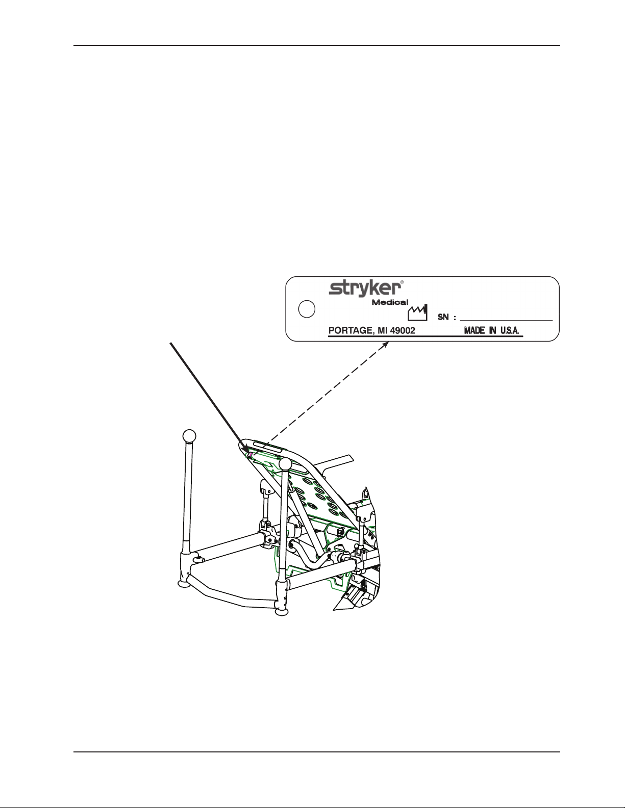
Please have the serial number (see Figure 1) of your Stryker product available when calling Stryker Customer Service
or Technical Support. Include the serial number in all written communication.
SERIAL NUMBER LOCATION
Serial Number
HEAD END
Figure 1: Cot Serial Number & Location
Return To Table of Contents
www.stryker.com 6550- 30 9- 001 REV A 11
Page 12
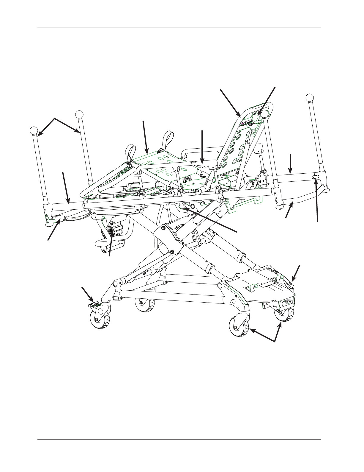
PRODUCT ILLUSTRATION
Introduction
Backrest
Backrest
Adjustment Handle
Push Bars
(Optional)
Retractable
Section
Height
Adjustment
Switch
Foot
Battery
Gatch/Leg
Rest
Siderail
Release
Hydraulic Unit
Retractable
Head
Section
Lifting Bar
Steer Lock
Head
Section
Release
Wheel Lock
Casters
Figure 2: Cot Components
Return To Table of Contents
12 6550-309 -0 01 REV A www.stryker.com
Page 13

Summary of Safety Precautions
Carefully read and strictly follow the warnings and cautions listed on these pages. Service only by qualified personnel.
WARNING
• Improper usage of the cot can cause injury to the patient or operator. Operate the cot only as described in this
manual.
• Do not modify the cot or any components of the cot. Modifying the product can cause unpredictable operation
resulting in injury to the patient or operator. Modifying the product also voids its warranty (see page 148).
• It is the responsibility of the cot operator to ensure that the cot being used in the Stryker Cot Fastener Systems
meets the installation specifications listed on page 22. Injury may result if a non-compatible cot is used in the
Stryker Fastener System.
• Do not attempt to operate the cot when it is loaded into a cot fastener.
• Entanglement in powered cot mechanisms can cause serious injury. Operate the cot only when all persons are
clear of the mechanisms.
• Practice changing height positions and loading the cot until operation of the product is fully understood. Improper
use can cause injury.
• Do not allow untrained assistants to assist in the operation of the cot. Untrained technicians/assistants can cause
injury to the patient or themselves.
• Ensure proper hand placement on hand grips.
• Do not ride on the base of the cot. Damage to the product could occur, resulting in injury to the patient or operator.
• Transporting the cot sideways can cause the cot to tip, resulting in possible damage to the product and/or injury to the
patient or operator. Transporting the cot in a lowered position, head or foot end first, minimizes the potential of a cot tip.
• Grasping the cot improperly can cause injury. Keep hands, fingers and feet away from moving parts. To avoid
injury, use extreme caution when placing your hands and feet near the base tubes while raising and lowering the
cot.
• Always use all restraint straps to secure the patient on the cot. An unrestrained patient may fall from the cot and
be injured.
• Never leave a patient unattended on the cot or injury could result. Hold the cot securely while a patient is on the
product.
• Never apply the wheel lock(s) while a patient is on the cot. Tipping could occur if the cot is moved while the wheel
lock is applied, resulting in injury to the patient or operator and/or damage to the cot.
• Siderails are not intended to serve as a patient restraint device. See page 38 for proper restraint strap usage.
Failure to utilize the siderails properly could result in patient injury.
• A minimum of two operators are required to transport a patient on the cot.
• In addition to the head and foot end, larger patients may require additional operators.
• Hydraulically raising or lowering the cot may temporarily affect electronic patient monitoring equipment. For best
results, patient monitoring should be conducted when the cot is idle.
• High obstacles, such as curbing, steps or rough terrain, can cause the cot to tip, possibly causing injury to the
patient or operator.
• Transporting the cot in lower positions reduces the potential of a cot tip. If possible, obtain additional assistance
or take an alternate route.
• A lift gate stop which is not properly functioning can result in injury to the patient or operator; ensure that the cot is
unable to roll back off of the lift before using the lift with a cot and patient. Verify the lift gate stop is maintained
and functioning properly and ensure that the cot is secure at all times when on the tail lift.
• Whenever the weight of the cot and patient is off of the wheels, the cot will automatically enter the high speed
retract mode if the retract (–) button is pressed.
• Once the weight is off of the ground, the operator(s) must support the load of the patient, cot and any accessories.
Failure to support the load properly may cause injury to the patient or operator.
• To avoid risk of electric shock, never attempt to open the battery pack for any reason. If the battery pack case
is cracked or damaged, do not insert it into the charger. Return damaged battery packs to a service center for
recycling.
• Do not remove the battery when the cot is activated.
• Avoid direct contact with a wet battery or battery enclosure. Contact may cause injury to the patient or operator.
• Always use all restraint straps to secure the patient on the cot. An unrestrained patient may fall from the cot and
be injured.
Return To Table of Contents
www.stryker.com 6550- 30 9- 001 REV A 13
Page 14

Summary of Safety Precautions
WARNING (CONTINUED)
• Do not attach restraints to the base or cross tubes, improper restraint attachment could result in damage to the
cot further resulting in injury to the patient or operator.
• Never install or use a wheel lock on a cot with excessively worn wheels. Installing or using a wheel lock on a wheel
with less than a 6 in diameter could compromise the holding ability of the wheel lock, possibly resulting in injury
to the patient or operator and/or damage to the cot or other equipment.
• Ensure that the push bar is properly locked into its mount to prevent the bar from coming out during use and
possibly injuring the operator and/or patient.
• Do not lift the cot with the push bars. Lifting the cot by the push bars may result in failure of the push bar lock
mechanism and may injure the operator and/or patient.
• When not in use, store the push bars in the base storage pouch that is provided with the push bar option.
• To avoid accidental release of the Pedi-Mate®, and possible injury to the infant, ensure that the restraint buckle is
located away from obstructions on the cot or accessories.
• Use of power washing equipment can aerate contamination collected during the use of the cot. Use any appropriate
personal safety equipment (goggles, respirator, etc.) to avoid the risk of inhaling contagion.
• SOME CLEANING PRODUCTS ARE CORROSIVE IN NATURE AND MAY CAUSE DAMAGE TO THE PRODUCT
IF USED IMPROPERLY. If the products described above are used to clean Stryker EMS equipment, measures
must be taken to insure the cots are wiped with clean water and thoroughly dried following cleaning. Failure to
properly rinse and dry the cots will leave a corrosive residue on the surface of the cots, possibly causing premature
corrosion of critical components.
• Failure to properly clean or dispose of contaminated mattress or other cot components will increase the risk of
bloodborne pathogens and may cause injury to the patient or operator.
• Escaping fluid under pressure can penetrate the skin causing serious injury. Avoid the hazard by relieving pressure
before disconnecting hydraulic or other lines. Tighten all connections before applying pressure. If an accident
occurs, see a doctor immediately. Any fluid injected into the skin must be surgically removed within a few hours or
gangrene may result. Doctors unfamiliar with this type of injury should reference a knowledgeable medical source.
• To avoid the risk of injury, do not use bare hands to check for hydraulic leaks.
• Medical electrical equipment requires special precautions regarding EMC and needs to be installed and put into
service according to the EMC information provided on page 144 to prevent equipment malfunction. Portable and
mobile RF communication equipment can affect Medical Electrical Equipment.
• Explosion Hazard - Do not use cot in presence of flammable anesthetics.
CAUTION
• When charging a battery in an ambulance, locate the charger in an enclosed cabinet and out of patient reach
during transport.
• The unit must be in its lowest position to properly engage the cot fastener (not included). To ensure that the cot
is in the lowest position, press the retract (-) button until the cot stops moving down. This should be done before
attempting to engage the cot into the cot fastener (not included).
• To reduce the risk of damage to the cot or cot fastener, do not attempt to activate the cot height activation while
it is engaged in the cot fastener (not included).
• Before operating the cot, clear any obstacles that may interfere and cause injury to the operator or patient.
• Remove the battery if the cot is not going to be used for an extended period of time (more than 24 hours).
• Only use the battery and charger as specified.
• The cot is not for use with an AC adapter.
• Ensure that the battery is fully charged prior to placing into service. An uncharged or depleted battery may cause
poor cot performance.
• Ensure that the restraints are not entangled in the base frame when raising and lowering the cot.
• Never operate the cot with the head section or foot section in an unlocked position.
• Wheel lock(s) are only intended to help prevent the cot from rolling while unattended and to aid in patient transfer.
A wheel lock may not provide sufficient resistance on all surfaces or under loads.
Return To Table of Contents
14 6550 -309 - 001 REV A www.stryker.com
Page 15

Summary of Safety Precautions
CAUTION (CONTINUED)
• Engaging the steer lock and attempting to push the cot sideways may affect the cot stability.
• To avoid damage to the I.V. pole, the weight of the I.V. bags or equipment must not exceed 2.8 stones (18 kg) (40
lb).
• To avoid damage to the equipment hook, the weight of the accessories or equipment must not exceed 2.5 stones
(16 kg) (35 lb).
• To avoid damage to the equipment hook, remove all accessories or equipment from the hook while transporting
the stretcher in the ambulance.
• Do not store items under the cot mattress. Storing items under the mattress can interfere with the operation of
the cot.
• The weight of the equipment in the pocketed backrest storage pouch (if equipped) must not exceed 1.4 stones
(9 kg) (20 lb).
• Ensure that the storage pouch does not interfere with the operation of the retractable head section.
• To avoid damage to the oxygen bottle holder (if equipped), the weight of the equipment must not exceed 2.9 stones
(18 kg) (40 lb).
• Only use oxygen bottles which lie within the width of the cot and are large enough to be firmly held by the straps.
• DO NOT STEAM CLEAN OR ULTRASONICALLY CLEAN THE UNIT.
• Maximum water temperature should not exceed 82°C/180°F.
• Maximum air dry temperature (cart washers) is 115°C/240°F.
• Maximum water pressure should not exceed 130.5 bar/1500 psi. If a hand held wand is being used to wash the
unit, the pressure nozzle must be kept a minimum of 61 cm (24 inches) from the unit.
• Towel dry all casters and interface points.
• Failure to comply with these instructions may invalidate any/all warranties.
• Always remove the battery before washing the cot.
• A preventative maintenance program should be established for all Stryker EMS equipment. Preventative
maintenance may need to be performed more frequently based on the usage level of the product. Close attention
should be given to safety features including, but not limited to:
• Hydraulic power mechanism
• All electrical controls return to off or neutral position when released
For additional maintenance information, see the preventative maintenance information.
• Improper maintenance can cause injury or damage to the product. Maintain the cot as described in this manual.
Use only Stryker approved parts and maintenance procedures. Using unapproved parts and procedures could
cause unpredictable operation and/or injury and will void the product warranty (see page 148).
• Failure to use authorized parts, lubricants, etc. could cause damage to the cot and will void the warranty of the
product.
• Hydraulic lines, hoses, and connections can fail or loosen due to physical damage, kinks, age, and exposure.
Check hoses and lines regularly to avoid damage to the cot. Check and tighten loose connections.
• Do not tip the cot and actuate the product as this will allow air to enter the hydraulic system.
• Do not lubricate the bearings in the X-frame as it will degrade the performance of the cot and may void its warranty
(see page 148).
• The weight of the monitoring equipment must not exceed 5.4 stones (34 kg) (75 lb) on the defibrillator platform
(if equipped). Monitoring equipment should not be stored on the cot or on the defibrillator platform when in the
ambulance vehicle.
• To avoid malfunction, do not use the unit adjacent to or stacked with other equipment. If adjacent or stacked use
is necessary, observe the unit to verify normal operation in the configuration in which it will be used.
• Possible fire hazard when used with oxygen administering equipment of other than the nasal, mask or 1/2 bed
length tent type. Oxygen tent should not extend below mattress support level. An oxygen rich environment is an
environment where the oxygen concentration levels are greater than 25% for ambient pressures up to 110 kPa or the
partial pressure of oxygen is greater than 27.5 kPa at ambient pressures exceeding 110 kPa.
Return To Table of Contents
www.stryker.com 6550- 30 9- 001 REV A 15
Page 16

Summary of Safety Precautions
NOTE
• Loose items or debris on the patient compartment floor can interfere with the operation of the cot fastener. Keep
the patient compartment floor clear.
• This manual should be considered a permanent part of the cot and should remain with the product even if the cot
is subsequently sold.
• Stryker continually seeks advancements in product design and quality. Therefore, while this manual contains the
most current product information available at the time of printing, there may be minor discrepancies between your
cot and this manual. If you have any questions, please contact Stryker Customer Service or Technical Support
at +44 (0) 1635 262431.
• The operators must lift the cot weight slightly off of the wheels to use the manual extend or retract while a patient
is on the cot.
• Activation of the manual back-up release handle may cause the cot to drop slowly if less than 7 stones (45 kg)
(100 lb) are on the cot.
• Batteries slowly lose charge when not on the charger.
• Lowering the backrest without a patient may require slightly more pressure.
• When engaging the cot into the fastener, it is advised to disengage the caster steer lock feature to allow the head
end casters to swivel freely and allow the head end of the cot to more easily align with the fastener.
• These are general instructions for installation of the Pedi-Mate®. Safe and proper use of the Pedi-Mate® is solely
at the discretion of the user. Stryker recommends that all users be trained on the proper use of the Pedi-Mate®
before using it in an actual situation. Retain these instructions for future reference. Include them with the product
in the event of transfer to new users.
• Failure to follow the cleaning directions when using the specified types of cleaners may void this product’s
warranty (see page 148).
Return To Table of Contents
16 655 0- 30 9-0 01 REV A w ww.stryker.com
Page 17
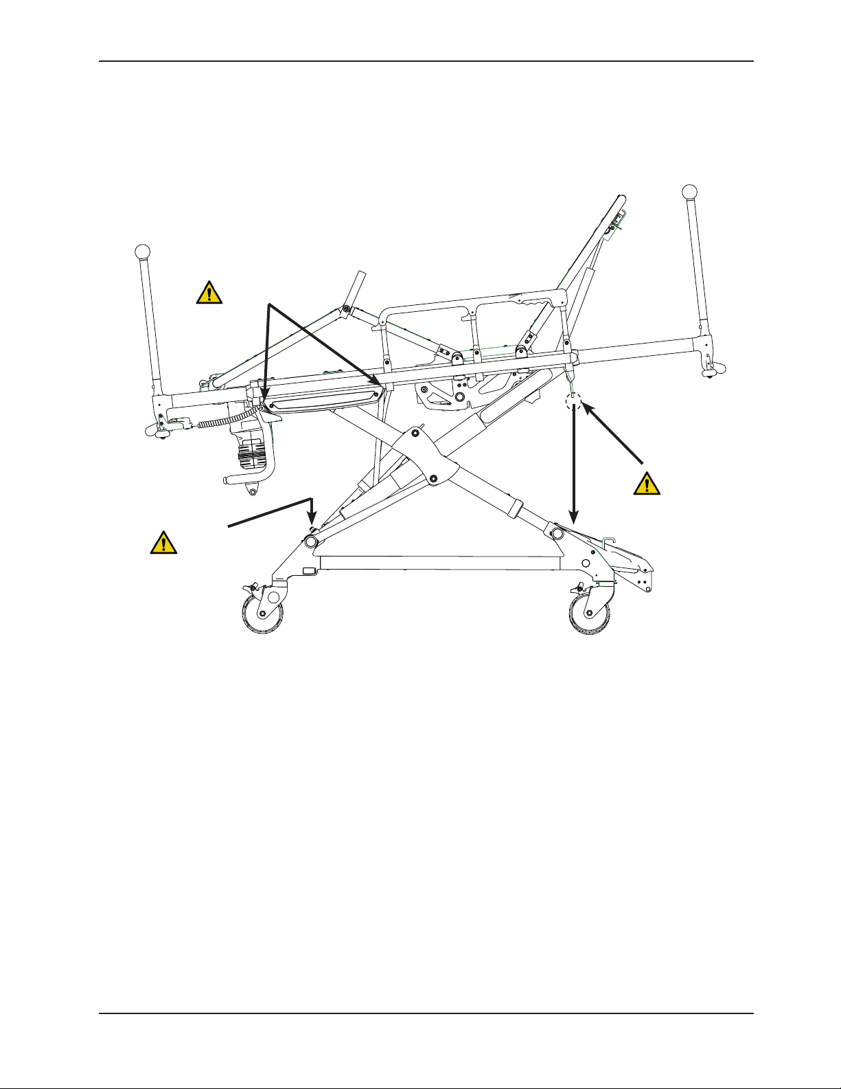
PINCH POINTS
Summary of Safety Precautions
WARNING: Pinch
Point
WARNING: Pinch
Point
WARNING: Pinch
Point between
litter interface
and base when
lowering litter.
Figure 3: Potential Pinch Points
Return To Table of Contents
www.stryker.com 6550- 30 9- 001 REV A 17
Page 18

Setup Procedures
Ensure that all shipping and packaging materials have been removed from the product(s) prior to use.
Unpack the cartons and check all items for proper operation. It is important that the cot is working properly before
it is put into service. Have a qualified service person use the Product Inspection checklist on page 19 and the
operation instructions to check the cot before it is put into service. See Figure 2 on page 12 to identify all of the
cot components.
The patient compartment of the vehicle in which the cot will be used must have a:
• Levelfloorlargeenoughforthefoldedcot.
• Stryker Model 6385, 6386, 6387, 6388, or 6389 Cot Fastener System (not included).
Note: Loose items or debris on the patient compartment floor can interfere with the operation of the cot fastener.
Keep the patient compartment floor clear.
When necessary, modify the vehicle to fit the cot. Do not modify the cot.
WARNING
• Improper usage of the cot can cause injury to the patient or operator. Operate the cot only as described in this
manual.
• Do not modify the cot or any components of the cot. Modifying the product can cause unpredictable operation
resulting in injury to the patient or operator. Modifying the product also voids its warranty (see page 148).
Note:
• This manual should be considered a permanent part of the cot and should remain with the product even if the cot
is subsequently sold.
• Stryker continually seeks advancements in product design and quality. Therefore, while this manual contains the
most current product information available at the time of printing, there may be minor discrepancies between your
cot and this manual. If you have any questions, please contact Stryker Customer Service or Technical Support
at +44 (0) 1635 262431.
Return To Table of Contents
18 655 0- 30 9-0 01 REV A w ww.stryker.com
Page 19

Product Inspection
The condition of the cot is the responsibility of the owner. It is important that the cot is working properly before the
product is put into service. Have a qualified service technician use the following list and the operation instructions to
check the cot before the product is put into service.
The battery must be charged prior to checking the features and condition of the cot.
Item Routine
Battery Unpack batteries and charger
Charge battery according to SMRT Power System instructions (6500-009-101) or DeWALT®
Battery System instructions
The power indicator LED, located on the height adjustment switch of the cot, is solid green when the battery is fully
charged or has adequately charged battery power.
CAUTION
When charging a battery in an ambulance, locate the charger in an enclosed cabinet and out of patient reach during
transport.
After the battery is fully charged, inspect the cot for the following points:
Item Routine Page
Battery Charge spare battery (if necessary) according to SMRT Pak or DeWA LT®
battery instructions
Install battery into foot end enclosure - power indicator LED operates 34
Ensure that the battery remains firmly secured 34
Release and remove battery from foot end enclosure 34
Reinstall battery into foot end enclosure 34
Hydraulics Inspect motor mount - all fasteners secure 62
Check cylinder attachments at both ends - all fasteners secure 62
Inspect main cable - all connections secure 62
Inspect hoses and cylinder seal for leaks 62
Electronic
Controls
Manual Back-up
Release
Litter All fasteners secure (reference all assembly drawings)
Check power indicator LED - charged 36
Extend cot to raised position 31
Check high speed retract 31
Extend cot to full height - no drift 31
Verify the manual back-up release handle functions properly - adjust
accordingly
With the cot empty, check the raise/lower function 32
With the cot loaded with a minimum of 7 stones (45 kg) (100 lb), check the
raise/lower function
All welds intact - not cracked or broken
No bent, broken, or damaged components
Verify siderails operate and latch properly 41
Verify backrest cylinder operates properly through range of motion 41
Verify the footrest operates properly 43
Install body restraints. Restraints intact and operating properly. 38
No rips or tears in mattress cover
34
32
32
Return To Table of Contents
www.stryker.com 6550- 30 9- 001 REV A 19
Page 20

Product Inspection
Item Routine Page
Head/Foot Section All fasteners secure (reference all assembly drawings)
No bent or broken tubing or sheet metal
Verify the head/foot section extends and retracts properly 42
Base All fasteners secure (reference all assembly drawings)
All welds intact - not cracked or broken
No bent, broken, or damaged components
Wheels and Tires No debris in wheels
All wheels secure, rolling and swiveling properly
Operate wheel locks (if equipped) - wheel secure when engaged,
rolls freely when disengaged
Accessories Verify I.V. pole (if equipped) operates properly 47
Verify removable oxygen bottle holder (if equipped) operates properly
Verify equipment hook (if equipped) is installed properly 50
Verify Pedi-Mate® restraint package (if equipped) is installed properly 51
Verify pocketed backrest storage pouch (if equipped) is installed properly 53
Verify oxygen bottle holder (if equipped) operates properly 54
Verify 36 in restraint extender (if equipped) is included 40
44
Return To Table of Contents
20 6550- 30 9- 001 REV A www.stryker.com
Page 21

Cot Fastener Installation
The Power-PRO TL Cot Fastener System, Model 6385, 6386, 6387, 6388, and 6389, are designed to be compatible
only with cots which conform to the installation specifications listed on page 22.
The Power-PRO TL Cot Fastener System, Model 6385, 6386, 6387, 6388, and 6389, are not designed for any other
purpose than to restrict cot movement as it is being transported in the patient compartment of an ambulance under
normal conditions. Usage of this product in any other way becomes the complete responsibility of the owner/user.
Caution must be used at all times during placement of the cot into the ambulance.
WARNING
It is the responsibility of the cot operator to ensure that the cot being used in the Stryker Cot Fastener Systems meets the
installation specifications listed on page 22. Injury may result if a non-compatible cot is used in the Stryker Fastener
System.
For more information about the Power-PRO TL Cot Fastener System, Model 63585, 6386, 6387, 6388, and 6389, see
the Cot Fastener Operations/Maintenance Manual (6385-009-001).
Return To Table of Contents
www.stryker.com 6550- 30 9- 001 REV A 21
Page 22
Cot Fastener Installation
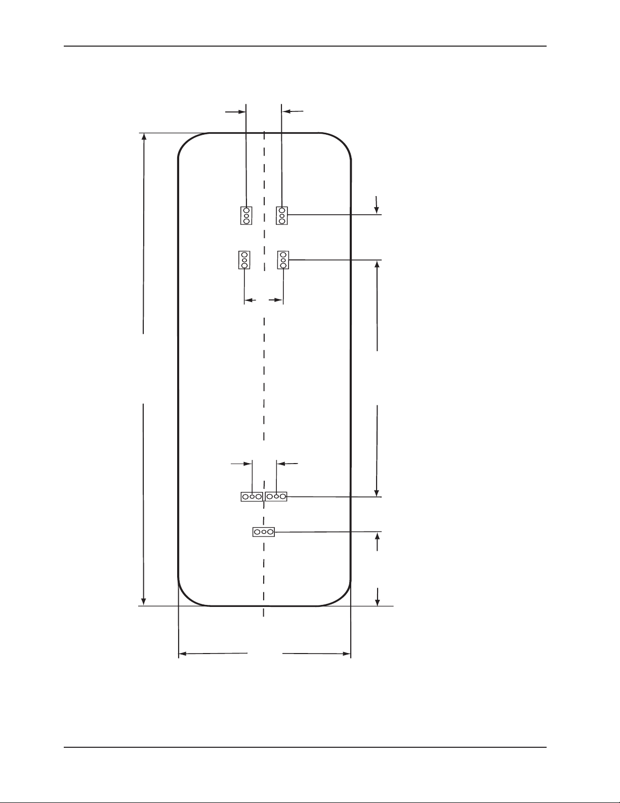
1925 MM (REF)
320 MM
150 MM
1015 MM 194 MM
610 MM (REF)
HEAD END
FRONT
OF
VEHICLE
FOOT END
120 MM
140 MM
RECOMMEND 370 MM FROM CENTERLINE OF COT TO VEHICLE SIDEWALL TO ALLOW FOR ROTATION OF THE WHEELS
CENTERLINE OF COT MUST BE PARALLEL TO VEHICLE WALL
90 MM
Note: Floor plates spaced evenly around centerline of cot.
Cot Length
Cot Width
Figure 4: Installation Specifications
Return To Table of Contents
22 6550- 30 9- 001 REV A www.stryker.com
Page 23
Operation Guide
ENGAGING THE COT INTO THE FASTENER
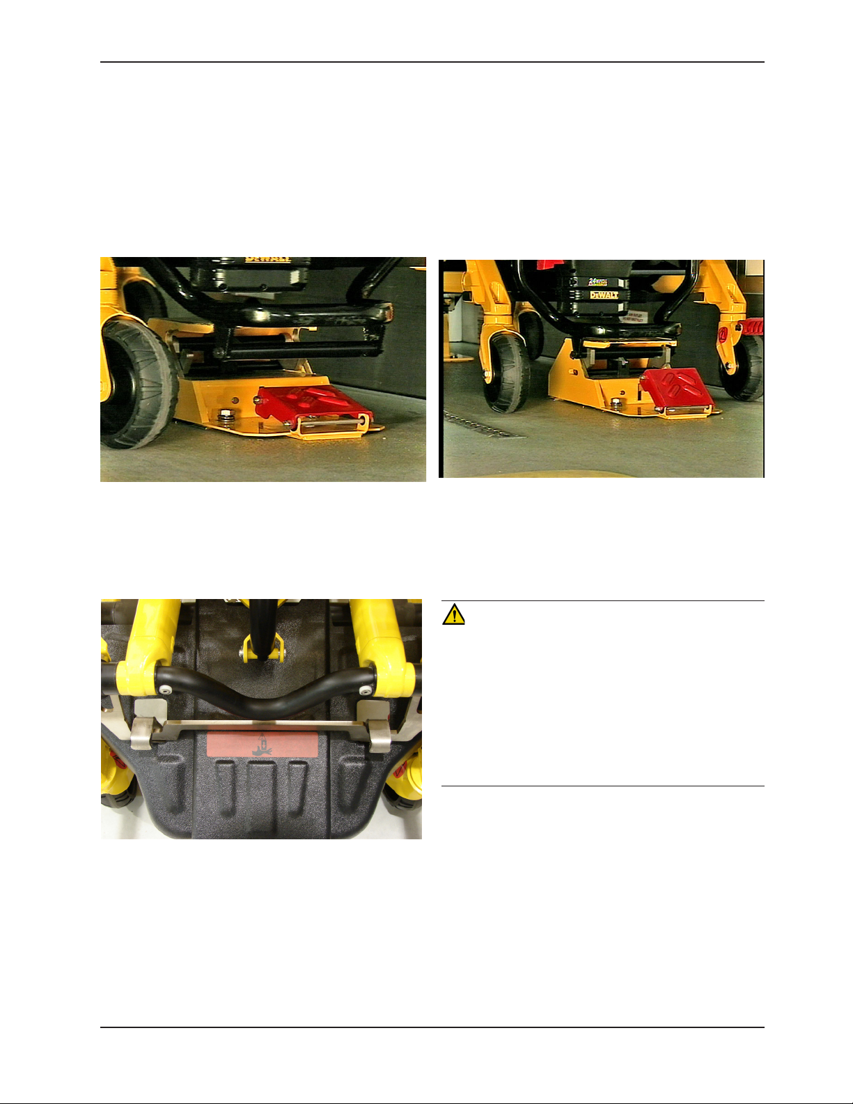
To engage the cot into the fastener:
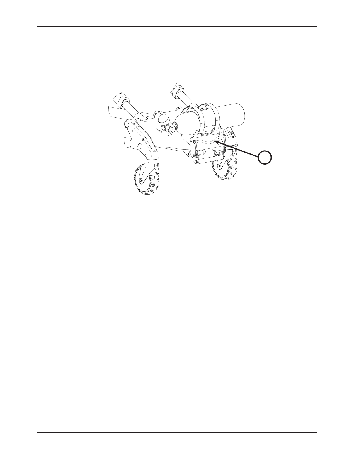
1. Before attempting to engage the cot into the fastener, ensure that the pedal is fully depressed and the cot is completely
lowered as shown in Figure 5.
2. Guide the cot into both the head end and foot end of the fastener until the locking mechanism is engaged as shown in
Figure 6.
Figure 5: Pedal Fully Depressed Figure 6: Cot in Fastener - (Foot End)
3. Make sure that the cot is securely fastened at both the head end and foot end before releasing your grip on the
cot as shown in Figure 7.
CAUTION
•The unit must be in its lowest position to properly engage
the cot fastener (not included). To ensure that the cot is
in the lowest position, press the retract (-) button until
the cot stops moving down. This should be done before
attempting to engage the cot into the cot fastener (not
included).
•To reduce the risk of damage to the cot or cot fastener,
do not attempt to activate the cot height activation while it
is engaged in the cot fastener (not included).
Figure 7: Cot in Fastener (Head End)
Return To Table of Contents
www.stryker.com 6550- 30 9- 001 REV A 23
Page 24

Operation Guide
REMOVING THE COT FROM THE FASTENER
To remove the cot from the fastener:
1. Press down firmly on the foot pedal until the locking mechanism disengages as shown in Figure 8.
2. Roll the cot out of the patient compartment as shown in Figure 9.
Figure 8: Press Foot End Figure 9: Remove Cot
Return To Table of Contents
24 6550- 309- 001 REV A www.stryker.com
Page 25

Operation Guide
OPERATING GUIDELINES
• Usethecotonlyasdescribedinthismanual.
• Readalllabelsandinstructionsonthecotbeforeusingthecot.
• Useaminimumoftwo(2)trainedoperatorstooperatethecotwhileapatientisonthecot.Ifadditionalassistance
is needed, see “Using Additional Assistance” on page 33.
• Donotadjust,rollorloadthecotintoavehiclewithoutadvisingthepatient.Staywiththepatientandcontrolthe
cot at all times.
• Thecotcanbetransportedinanyposition.Strykerrecommendsthattheoperatorstransportthepatientinthe
lowest comfortable position to maneuver the cot.
• Onlyusethewheellock(s)duringpatienttransferorwithoutapatientonthecot.
• Alwaysusetherestraintstraps.
• Useproperlytrainedhelperswhennecessarytocontrolthecotandpatient.
WARNING
• Improper usage of the cot can cause injury to the patient or operator. Operate the cot only as described in this
manual.
• Entanglement in powered cot mechanisms can cause serious injury. Operate the cot only when all persons are
clear of the mechanisms.
• Practice changing height positions and loading the cot until operation of the product is fully understood. Improper
use can cause injury.
• Do not allow untrained assistants to assist in the operation of the cot. Untrained technicians/assistants can cause
injury to the patient or themselves.
• Ensure proper hand placement on hand grips.
• Do not ride on the base of the cot. Damage to the product could occur, resulting in injury to the patient or operator.
• Transporting the cot sideways can cause the cot to tip, resulting in possible damage to the product and/or injury to the
patient or operator. Transporting the cot in a lowered position, head or foot end first, minimizes the potential of a cot tip.
• Grasping the cot improperly can cause injury. Keep hands, fingers and feet away from moving parts. To avoid injury,
use extreme caution when placing your hands and feet near the base tubes while raising and lowering the cot.
CAUTION
Before operating the cot, clear any obstacles that may interfere and cause injury to the operator or patient.
PROPER LIFTING TECHNIQUES
When lifting the cot and patient, there are five basic guidelines to help you avoid injury:
• Keep your hands close to your body.
• Keep your back straight.
• Coordinate your movements with your partner and lift with your legs.
• Avoid twisting.
• Always operate the cot as described in this manual.
Return To Table of Contents
www.stryker.com 6550- 30 9- 001 REV A 25
Page 26

Operation Guide
TRANSFERRING THE PATIENT TO THE COT
To transfer the patient to the cot:
1. Roll the cot to the patient.
2. Place the cot beside the patient and raise or lower the cot to the level of the patient.
3. Lower the siderails and open the restraint straps.
4. Engage the wheel locks to prevent the cot from moving during patient transfer.
5. Transfer the patient to the cot using accepted EMS procedures.
6. Use all the restraint straps to secure the patient to the cot (see page 38).
7. Raise the siderails and adjust the backrest and leg rest as necessary.
8. Disengage the wheel locks for transport.
WARNING
• Always use all restraint straps to secure the patient on the cot. An unrestrained patient may fall from the cot and
be injured.
• Never leave a patient unattended on the cot or injury could result. Hold the cot securely while a patient is on the
product.
• Never apply the wheel lock(s) while a patient is on the cot. Tipping could occur if the cot is moved while the wheel
lock is applied, resulting in injury to the patient or operator and/or damage to the cot.
• Siderails are not intended to serve as a patient restraint device. See page 38 for proper restraint strap usage.
Failure to utilize the siderails properly could result in patient injury.
• Hydraulically raising or lowering the cot may temporarily affect electronic patient monitoring equipment. For best
results, patient monitoring should be conducted when the cot is idle.
ROLLING THE COT
WARNING
• A minimum of two operators are required to transport a patient on the cot.
• In addition to the head and foot end, larger patients may require additional operators.
The Power-PRO TL cot can transport a patient in any height position, however, lower heights may improve balance
and stability, so Stryker recommends keeping the cot in the lowest position that is comfortable for the cot operators.
When rolling the cot:
• Make sure that all of the restraint straps are securely buckled around the patient (see page 38).
• Place the cot in any position for rolling.
• Position an operator at the foot end and one at the head end of the cot at all times when rolling the cot with a
patient on it.
• Approach door sills and/or other low obstacles squarely and lift each set of wheels over the obstacle separately.
WARNING
• High obstacles, such as curbing, steps or rough terrain, can cause the cot to tip, possibly causing injury to the
patient or operator.
• Transporting the cot in lower positions reduces the potential of a cot tip. If possible, obtain additional assistance or
take an alternate route.
Return To Table of Contents
26 655 0- 30 9-0 01 REV A w ww.stryker.com
Page 27

Operation Guide
ADJUSTING THE HEIGHT OF THE COT WITH TWO OPERATORS
Changing the height of the cot while a patient is on the cot requires a minimum of two (2) trained operators who are
positioned at each end of the cot.
To raise or lower the cot:
1. Operator 1 (Foot End) − Grasp the cot frame at the foot end and press either the extend (+) button on the control
switch to raise the litter or the (–) button on the control switch to lower the litter to the desired position.
2. Operator 2 (Head End) − Maintain a firm grip on the outer rail until the cot is securely in the desired position.
WARNING
Grasping the cot improperly can cause injury. Keep hands, fingers and feet away from moving parts. To avoid injury, use
extreme caution when placing your hands and feet near the base tubes while raising and lowering the cot.
Return To Table of Contents
www.stryker.com 6550- 30 9- 001 REV A 27
Page 28
Operation Guide
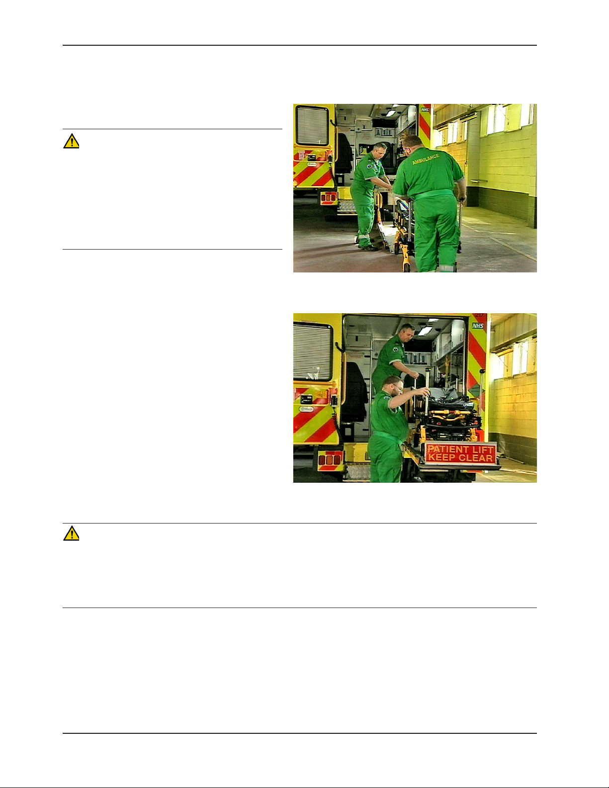
TAIL LIFT LOADING AND UNLOADING
Loading an occupied cot into a vehicle requires a
minimum of two (2) trained operators.
WARNING
• A lift gate stop which is not properly functioning can
result in injury to the patient or operator; ensure
that the cot is unable to roll back off of the lift
before using the lift with a cot and patient. Verify
the lift gate stop is maintained and functioning
properly and ensure that the cot is secure at all
times when on the tail lift.
• Ensure proper hand placement on hand grips.
To load the cot:
1. Ensure that the patient is secured at all times while
on the cot.
2. Move the cot to its lowest position for greater
stability by pressing the retract (-) button.
3. Push the cot forward onto the tail lift, head end
first as shown in Figure 10. Ensure that the wheels
are in the proper location on the tail lift to allow the
safety stop to properly rotate in place and prevent
the cot from rolling backwards as shown in Figure
11.
4. Before raising the tail lift, verify that there is
adequate distance between the cot and rear of
the ambulance, and that there is nothing hanging
down from the cot.
5. As one operator raises the tail lift, the second
operator should maintain a firm grip on the cot
frame to provide greater stability.
6. Both operators should carefully guide the cot into
the patient compartment and into the cot fastener
(not included).
Figure 10: Load Cot
Figure 11: Push Cot into Patient Compartment
CAUTION
• The unit must be in its lowest position to properly engage the cot fastener (not included). To ensure that the cot
is in the lowest position, press the retract (-) button until the cot stops moving down. This should be done before
attempting to engage the cot into the cot fastener (not included).
• To reduce the risk of damage to the cot or cot fastener, do not attempt to activate the cot height activation while it
is engaged in the cot fastener (not included).
To unload the cot:
1. Ensure that the safety gate stop is in position to prevent the cot from rolling off of the lift.
2. Raise the tail lift to the ambulance floor level and disengage the cot from the cot fastener system.
3. Both operators should firmly grasp the cot frame and roll the cot into the tail lift. Make sure that the cot is fully
removed from the patient compartment and the cot wheels are in the proper position to allow the lift to lower freely.
4. Lower the tail lift to the ground and ensure that it is fully lowered and stopped before disengaging the tail lift safety
gate and allowing the cot to be rolled off of the tail lift.
Return To Table of Contents
28 655 0-309-0 01 REV A w ww.stryker.com
Page 29
Operation Guide
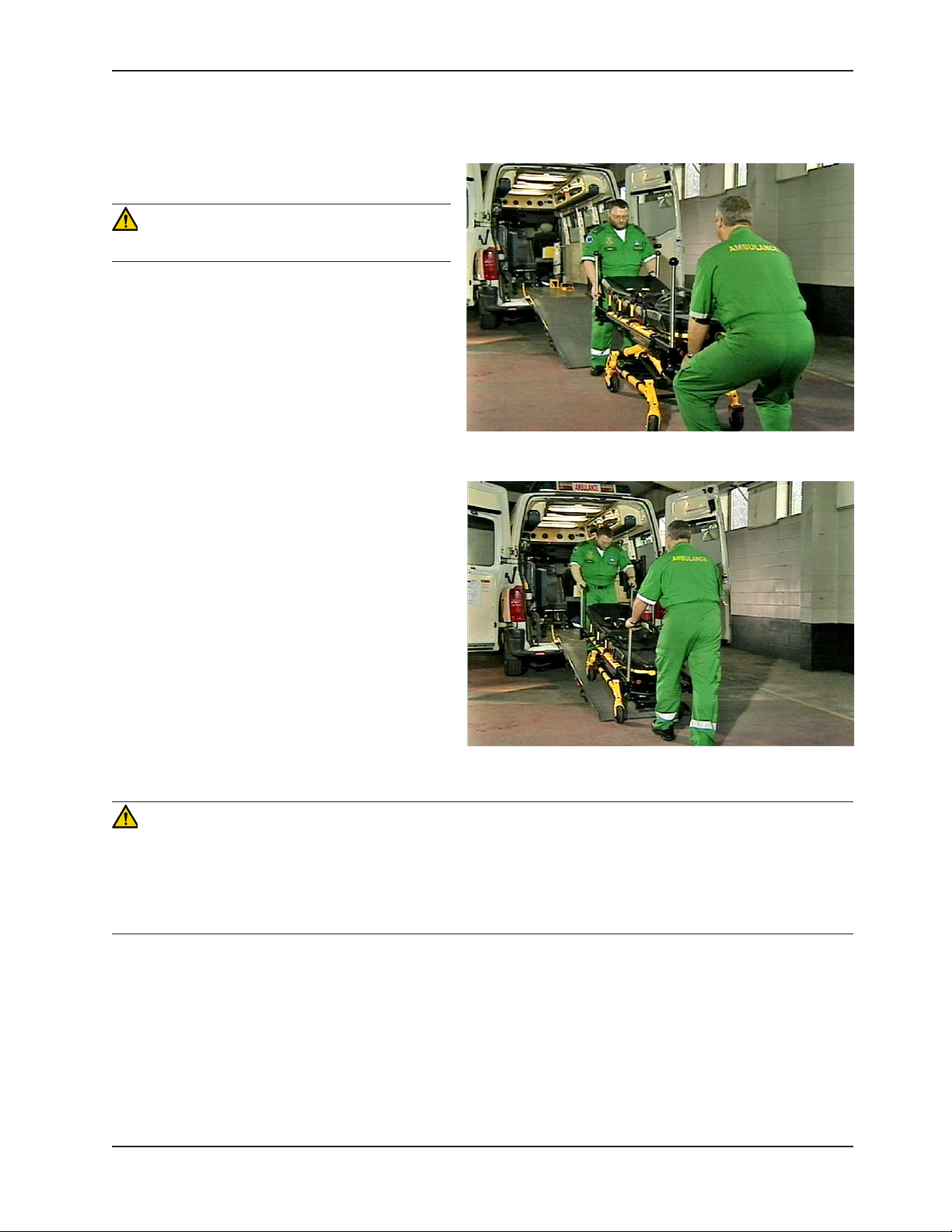
RAMP LOADING AND UNLOADING
Loading an occupied cot into a vehicle requires a
minimum of two (2) trained operators.
WARNING
Ensure proper hand placement on hand grips.
To load the cot:
1. Ensure that the patient is secured at all times
while on the cot.
2. Before pushing up the ramp, lower the cot to its
lowest position by pressing the retract (-) button
for maximum stability. Also verify that there is
nothing hanging down from the cot, such as
blankets or straps.
3. Using the optional push bars, both operators
should push/pull the cot up the ramp, head end
first. The operators should carefully guide the cot
up the center of the ramp as shown in Figure 13).
4. Both operators should then push the cot into the
patient compartment, until the cot engages the
cot fastener (not included).
Figure 12: Lower Cot
Figure 13: Push Cot in Patient Compartment
CAUTION
• The unit must be in its lowest position to properly engage the cot fastener (not included). To ensure that the cot
is in the lowest position, press the retract (-) button until the cot stops moving down. This should be done before
attempting to engage the cot into the cot fastener (not included).
• To reduce the risk of damage to the cot or cot fastener, do not attempt to activate the cot height activation while it
is engaged in the cot fastener (not included).
Return To Table of Contents
www.stryker.com 6550- 30 9- 001 REV A 29
Page 30
Cot Operation
LOADING AND UNLOADING THE COT USING THE OPTIONAL OXYGEN BOTTLE HOLDER
To load and unload the cot with the optional oxygen bottle holder, attach the winch cable to the winch attachment rod
(A) as shown in Figure 14.
A
Figure 14: Winch Attachment Rod
The length of the loading ramp should be at least 8.5 feet. Verify the ramp can support the weight of the cot, patient
and equipment.
Note:
• With the cot in the lowest position, the optional oxygen bottle holder can be used to load patients weighing up to
50 stones (318 kg) (700 lb).
• Proper inspection and maintenance of the optioanl oxygen bottle holder accessory should be followed as identified
in the Preventative Maintenance Checklist (see page 57).
Return To Table of Contents
30 6550 - 309- 001 REV A ww w.stryker.com
Page 31

Operation Guide
HIGH SPEED RETRACT/EXTEND
The cot is equipped with a high-speed retract mode to expedite lifting the cot over obstacles.
• Theundercarriagerapidly retracts toward the highest position once the weight of the cot and patient is off of the
wheels. Press the retract (–) button to actuate the control switch.
• Theundercarriagerapidly extends toward the lowest position once the weight of the cot and patient is off of the
wheels. Press the extend (+) button to actuate the control switch.
WARNING
• Whenever the weight of the cot and patient is off of the wheels, the cot will automatically enter the high speed
retract mode if the retract (–) button is pressed.
• Once the weight is off of the ground, the operator(s) must support the load of the patient, cot and any accessories.
Failure to support the load properly may cause injury to the patient or operator.
Return To Table of Contents
www.stryker.com 6550- 30 9- 001 REV A 31
Page 32

Operation Guide
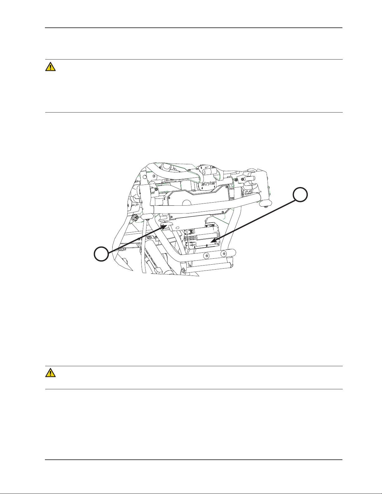
USING THE MANUAL OVERRIDE
In the event of loss of electrical function, the cot is equipped with a manual override to allow manual operation of the
product until electrical functionality is restored. You can use the red manual back-up release handle to raise or lower
the cot.
The red manual back-up release handle (A) is located along the patient left side of the lower lift bar at the foot end of
the cot as shown in Figure 15.
A
Figure 15: Manual Release Handle
To raise or lower the cot with the manual back-up release handle:
1. Both Operators − Lift the cot during the raise/lower operation to support the weight of the cot at each end.
2. Operator 1 (Foot End) − Pull the manual back-up release handle toward the lift bar. While the manual back-up
release handle is pulled, raise or lower the cot to the desired position and then release the handle to lock the cot
into position.
Note:
• The operators must lift the cot weight slightly off of the wheels to use the manual extend or retract while a patient
is on the cot.
• Activation of the manual back-up release handle may cause the cot to drop slowly if less than 7 stones (45 kg)
(100 lb) are on the cot.
Return To Table of Contents
32 655 0- 30 9-0 01 REV A w ww.stryker.com
Page 33

USING ADDITIONAL ASSISTANCE
Two Operators
Two Helpers
Two Operators
Operation Guide
Changing Levels Rolling
Helper
Operator
Helper
Helper
Operator
Helper
Operator
Operator
Helper
Helper
Helper
Helper Helper
Operator
Four Helpers
Operator
Helper
Helper
Operator
Helper
Operator
Return To Table of Contents
www.stryker.com 6550- 30 9- 001 REV A 33
Page 34

Operation Guide
REMOVING AND REPLACING THE BATTERY
The cot is supplied with two removable 24V SMRT Paks or 24V DeWALT® batteries as the power source.
See the SMRT Power System Operations/Maintenance manual (6500-009-101) for additional SMRT Pak and SMRT
Charger information. See the DeWALT® Battery System manual for battery and charger information.
REMOVING AND REPLACING A SMRT PAK
WARNING
• To avoid risk of electric shock, never attempt to open the battery pack for any reason. If the battery pack case
is cracked or damaged, do not insert it into the charger. Return damaged battery packs to a service center for
recycling.
• Do not remove the battery when the cot is activated.
• Avoid direct contact with a wet battery or battery enclosure. Contact may cause injury to the patient or operator.
To remove the SMRT Pak:
1. Press the RED one hand release button (C) or press the battery release button (A) to release the SMRT Pak (B)
from the cot as shown in Figure 16.
2. Slide the released SMRT Pak out of the enclosure.
B
A
C
Figure 16: SMRT Pak Removal and Replacement
To reinstall or replace the SMRT Pak:
1. Align the tabs in the battery enclosure.
2. Push the SMRT Pak into the enclosure until the latch clicks into place.
• The cot power indicator LED is solid GREEN if the SMRT Pak is fully charged and ready.
• The cot power indicator LED flashes RED if the SMRT Pak needs to be recharged or replaced.
Note: Batteries slowly lose charge when not on the charger.
CAUTION
Remove the battery if the cot is not going to be used for an extended period of time (more than 24 hours).
Return To Table of Contents
34 655 0- 30 9-0 01 REV A w ww.stryker.com
Page 35
Operation Guide
REMOVING AND REPLACING A DeWALT® BAT TE RY
WARNING
• To avoid risk of electric shock, never attempt to open the battery pack for any reason. If the battery pack case
is cracked or damaged, do not insert it into the charger. Return damaged battery packs to a service center for
recycling.
• Do not remove the battery when the cot is activated.
• Avoid direct contact with a wet battery or battery enclosure. Contact may cause injury to the patient or operator.
To remove the battery:
1. Press the red battery release button (A), located on the patient right side of the foot end control enclosure, to
release the battery (B) from the cot as shown in Figure 17.
2. Slide the released battery out of the enclosure.
B
A
Figure 17: DeWALT® Battery Removal & Replacement
To reinstall or replace the battery:
1. Align the tabs in the battery enclosure.
2. Push the battery into the enclosure until the latch clicks into place.
• The cot power indicator LED is solid GREEN if the battery is fully charged and ready.
• The cot power indicator LED flashes RED if the battery needs to be recharged or replaced.
Note: Batteries slowly lose charge when not on the charger.
CAUTION
Remove the battery if the cot is not going to be used for an extended period of time (more than 24 hours).
Return To Table of Contents
www.stryker.com 6550- 30 9- 001 REV A 35
Page 36

Operation Guide
USING THE BATTERY POWER INDICATOR
To check the battery power level, depress lightly on the retract (–) button (A) to activate the power indicator LED (B)
as shown in Figure 18.
The power indicator LED, located on the height adjustment switch of the cot, is represented by a red or green light.
• The indicator LED is solid green when the battery is fully charged or has adequately charged battery power.
• TheindicatorLEDflashesredwhenthebatteryneedstoberechargedorreplaced.
B
A
Figure 18: Battery Power Indicator
WARNING
• To avoid risk of electric shock, never attempt to open the battery pack for any reason. If the battery pack case
is cracked or damaged, do not insert it into the charger. Return damaged battery packs to a service center for
recycling.
• Do not remove the battery when the cot is activated.
• Avoid direct contact with a wet battery or battery enclosure. Contact may cause injury to the patient or operator.
CAUTION
• Only use the battery and charger as specified.
• The cot is not for use with an AC adapter.
• When charging a battery in an ambulance, locate the charger in an enclosed cabinet and out of patient reach
during transport.
• Ensure that the battery is fully charged prior to placing into service. An uncharged or depleted battery may cause
poor cot performance.
See the SMRT Power System Operations/Maintenance manual (6500-009-101) for additional SMRT Pak and SMRT
Charger information. See the DeWALT® Battery System manual for battery and charger information.
Return To Table of Contents
36 6550- 309- 001 REV A www.stryker.com
Page 37

Operation Guide
USING THE HOUR METER
The hour meter, located on the foot end control enclosure as shown in Figure 19, indicates the amount of time
(HHH.H hours) that the cot has been in use under power. You can use the hour meter to determine the frequency for
preventative maintenance procedures as listed on page 57.
A
Figure 19: Hour Meter
Return To Table of Contents
www.stryker.com 6550- 30 9- 001 REV A 37
Page 38

Operation Guide
USING RESTRAINT STRAPS
WARNING
Always use all restraint straps to secure the patient
on the cot. An unrestrained patient may fall from
the cot and be injured.
Always secure the patient on the cot with all of
the restraint straps. Buckle the restraints across
the patient’s chest/shoulders, waist and legs as
shown in Figure 20.1. Keep the restraint straps
buckled when the cot is not being used with a
patient to avoid damage to the buckles and straps.
WARNING
Do not attach restraints to the base or cross
tubes, improper restraint attachment could result in
damage to the cot further resulting in injury to the
patient or operator.
Figure 20.1: Safety Restraints
Figure 20.2: Head Section Restraints
To attach the patient restraint straps to the cot litter frame, feed the loop end of each strap through the litter frame at
each of the designated locations in Figure 20.2 and 20.3 and then feed the buckle or latch plate back through the loop
end of the strap. The arrows indicate alternate attachment areas.
When attaching the restraint straps to the cot, the attachment points should provide both strong anchorage and proper
restraint position while not interfering with equipment and accessories.
Return To Table of Contents
38 6550 - 309- 001 R EV A ww w.stryker.com
Figure 20.3: Foot Section Restraints
Page 39

Operation Guide
USING RESTRAINT STRAPS (CONTINUED)
CAUTION
Ensure that the restraints are not entangled in the base frame when raising and lowering the cot.
When the cot is put into service, open the restraints and place them at either side of the cot until the patient is
positioned on the cot mattress. Lengthen the restraints, buckle them around the patient and shorten them until the
required tightness is achieved.
• To open the restraint, press the red button (A) on the front of the buckle “receiver”. This releases the buckle latch
plate (B) which can then be pulled out of the receiver as shown in Figure 21.1.
• To close the restraint, push the latch plate into the receiver until a “click” is heard. When fastening the chest
restraint ensure that the latch plate passes through both links (C) on the shoulder strap as shown in Figure 21.1.
• To lengthen the restraint, grasp the buckle latch plate, turn it at an angle to the webbing, then pull it out as shown
in Figure 21.2. A hemmed tab at the end of the webbing prevents the latch plate from coming off of the strap.
• To shorten the restraint, grasp the hemmed tab and pull the webbing back through the latch plate until the
required tightness is achieved as shown in Figure 21.3.
C
C
A
Figure 21.1: Buckling the Safety Restraints
Whenever a restraint is buckled on a patient, verify that the latch plate is fully engaged and any extra webbing is not
tangled in the cot or hanging loose.
B
Figure 21.2: Lengthening the Safety
Restraint
Figure 21.3: Shortening the Safety Restraint
Inspect the restraints at least once a month (more frequently if used heavily). Inspection should include checking for a
bent or broken receiver or latch plate, torn or frayed webbing, etc. Any restraint showing wear or not operating properly
must be replaced immediately.
Return To Table of Contents
www.stryker.com 6550- 30 9- 001 REV A 39
Page 40

Operation Guide
USING THE OPTIONAL RESTRAINT BELT EXTENSION
Use the restraint belt extension (6082-160-050), as shown in Figure 22, for extra length when buckling the lap belt
around large patients.
Figure 22: Attaching the Restraint Belt Extension
Return To Table of Contents
40 6550 -309 - 001 REV A www.stryker.com
Page 41

Operation Guide
OPERATING THE BACKREST
To raise the backrest, as shown in Figure 23, squeeze handle (A) to move the backrest to the desired height.
To lower the backrest, squeeze handle (A) and push down on the backrest frame until the backrest has reached the
desired height.
Note: Lowering the backrest without a patient may require slightly more pressure.
A
B
Figure 23: Backrest Elevated and Siderails Raised
OPERATING THE SIDERAILS
To raise the siderails, as shown in Figure 23, lift up on the siderail until the latch clicks and the siderail locks into place.
When a patient is on the cot, always keep the siderails in the raised position unless the patient is being transferred.
To l o wer the siderails, squeeze handle (B) to release the siderail latch. Guide the siderail down toward the foot end
until flat.
WARNING
Siderails are not intended to serve as a patient restraint device. See page 38 for proper restraint strap usage. Failure
to utilize the siderails properly could result in patient injury.
Return To Table of Contents
www.stryker.com 6550- 30 9- 001 REV A 41
Page 42

Operation Guide
OPERATING THE RETRACTABLE HEAD AND FOOT SECTIONS
The head section telescopes from an extended position to a
retracted position within the litter frame.
To extend the head or foot section:
1. Squeeze the red release levers (A) on each side of the
frame as you pull the head or foot section out of its
retracted position as shown in Figure 24.1.
2. Make sure that the head or foot section is securely locked
into position.
To retract the head or foot section:
1. Squeeze the red release levers (A) on each side of the
frame as you push the head or foot section out of its
extended position as shown in Figure 24.2.
2. Make sure that the head or foot section is securely locked
into position.
CAUTION
Never operate the cot with the head section or foot section in
an unlocked position.
A
Figure 24.1: Head and Foot Section Extended
A
Figure 24.2: Head and Foot Section Retracted
Return To Table of Contents
42 6550- 30 9- 001 REV A www.stryker.com
Page 43

Operation Guide
ADJUSTING THE FOOTREST
The footrest is adjustable to elevate the patient’s legs as shown in Figure 25.
To raise the footrest, lift the footrest frame (A) as high as possible. The support bracket engages automatically when
released.
To lower the footrest, lift the footrest frame (A) and while holding the frame, lift up on the release handle (C) until the
bracket disengages. Lower the footrest until it is flat.
B
A
C
Figure 25: Footrest Elevated and Gatch Raised
To raise the gatch, lift either of the red lifting loops (B) until the gatch is in its fully raised position, then slowly lower
the gatch to allow the support bracket to engage into the locking mechanism. Make sure that the lock is fully engaged
before releasing the lifting loop.
To lower the gatch, lift either of the red lifting loops (B) to relieve pressure on the locking mechanism and while holding
the loop, lift up on the red release handle (C) until the bracket disengages. Lower the gatch to the flat position.
Return To Table of Contents
www.stryker.com 6550- 30 9- 001 REV A 43
Page 44

Operation Guide
OPERATING THE WHEEL LOCK(S)
The Power-PRO TL includes corner to corner wheel locks as a standard feature, with an option to specify locks for all
four wheels.
To secure the wheel lock(s), press down on the base of the locking pedal (A) until it rests firmly against the surface
of the wheel as shown in Figure 26.
To release the wheel lock(s), press the upper face of the pedal with your foot or lift up with your toe under the pedal.
The upper portion of the pedal will rest against the caster frame when the wheel lock is released.
A
Figure 26: Wheel Lock
WARNING
• Never apply the wheel lock(s) while a patient is on the cot. Tipping could occur if the cot is moved while a wheel
lock is applied, resulting in injury to the patient or operator and/or damage to the cot.
• Never leave a patient unattended on the cot or injury could result. Hold the cot securely while a patient is on the
cot.
• Never install or use a wheel lock on a cot with excessively worn wheels. Installing or using a wheel lock on a wheel
with less than a 6 in diameter could compromise the holding ability of the wheel lock, possibly resulting in injury to
the patient or operator and/or damage to the cot or other equipment.
CAUTION
Wheel lock(s) are only intended to help prevent the cot from rolling while unattended and to aid in patient transfer. A
wheel lock may not provide sufficient resistance on all surfaces or under loads.
Return To Table of Contents
44 6550 -309 - 001 REV A ww w.stryker.com
Page 45

Operation Guide
OPERATING THE CASTER STEER LOCK
The caster steer lock feature locks the head end caster to improve steering control and unlocks the caster to allow for
free swiveling for greater mobility.
CAUTION
Engaging the steer lock and attempting to push the cot sideways may affect the cot stability.
To engage the caster steer lock:
1. Press the front portion of the steer lock pedal as shown in Figure 27.1.
2. Push the cot toward the head end.
3. The caster swivels and aligns into the forward position and the steer lock engages.
Figure 27.1: Engage Caster Steer Lock
To disengage the caster steer lock:
1. Press the rear portion of the steer lock pedal as shown in Figure 27.2.
2. After the pedal is in the unlocked position, push the cot in any direction.
3. The casters swivel freely.
Note: When engaging the cot into the fastener, it is advised to disengage the caster steer lock feature to allow the
head end casters to swivel freely and allow the head end of the cot to more easily align with the fastener.
Figure 27.2: Disengage Caster Steer Lock
Return To Table of Contents
www.stryker.com 6550- 30 9- 001 REV A 45
Page 46

Operation Guide
INSTALLING THE PUSH BARS
The optional push bars allow you to maneuver the cot at any
height position.
To install the push bars:
1. Insert each bar into one of the four corner sockets.
2. Push down until each locking mechanism is fully engaged
as shown in Figure 28.1.
WARNING
• Ensure that the push bar is properly locked into its mount
to prevent the bar from coming out during use and possibly
injuring the operator and/or patient.
• Do not lift the cot with the push bars. Lifting the cot by
the push bars may result in failure of the push bar lock
mechanism and may injure the operator and/or patient.
REMOVING THE PUSH BARS
Figure 28.1: Installed Push Bar
To remove the push bars:
1. Press the red release button and lift each bar out of its
corner socket.
2. Place the removed push bars into the storage pouch that is
located on the base frame as shown in Figure 28.2.
WARNING
When not in use, store the push bars in the base storage pouch
that is provided with the push bar option.
ATTACHING THE PUSH BAR STORAGE POUCH
To attach the storage pouch:
1. Connect the corresponding buckles to secure the pouch to
the cot frame (A) as shown in Figure 28.3.
2. Ensure that the pouch and its contents do not interfere
with the cot operation before raising or lowering the cot or
transporting the cot.
Figure 28.2: Stored Push Bar
A
Figure 28.3: Push Bar Storage Pouch
Return To Table of Contents
46 6550 -309 - 001 REV A www.stryker.com
Page 47
Operation Guide
OPERATING THE OPTIONAL 2-STAGE I.V. POLE
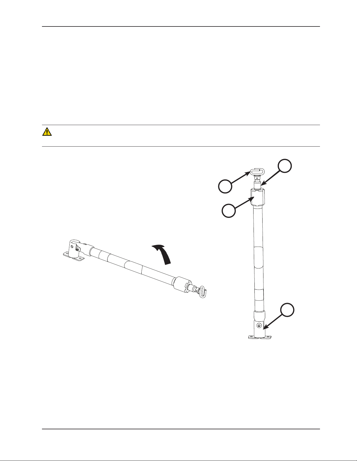
To use the 2-stage I.V. pole as shown in Figure 29.2):
1. Lift and pivot the pole from the storage position and push down until it is locked into the receptacle (A).
2. To raise the height of the pole, turn the lock actuator (B) counterclockwise and pull up on the telescoping portion
(C) of the pole to raise it to the desired height.
3. Turn the lock actuator (B) clockwise to lock the telescoping portion in place.
4. Hang the I.V. bags on the I.V. hook (D).
5. Turn the lock actuator (B) counterclockwise and slide section (C) into the bottom tube.
6. Turn the lock actuator (B) clockwise to tighten.
7. Lift up and pivot the pole down into the storage position as shown in Figure 29.1.
CAUTION
To avoid damage to the I.V. pole, the weight of the I.V. bags or equipment must not exceed 2.8 stones (18 kg) (40 lb).
C
C
D
D
Figure 29.1: 2-Stage I.V. Pole Storage Position
B
B
A
A
Figure 29.2: 2-Stage I.V. Pole
Return To Table of Contents
www.stryker.com 6550- 30 9- 001 REV A 47
Page 48

Operation Guide
OPERATING THE OPTIONAL 3-STAGE I.V. POLE
To use the 3-stage I.V. pole as shown in Figure 30.2):
1. Lift and pivot the pole from the storage position and push down
until it is locked into the receptacle (A).
2. To raise the height of the pole, turn the lock actuator (B)
counterclockwise and pull up on the bottom telescoping portion
(C) of the pole to raise it to the desired height.
3. Turn the lock actuator (B) clockwise to lock the bottom telescoping
portion in place.
4. For a higher I.V. pole, pull up on section (D) until the spring clip
(E) engages.
5. Hang I.V. bags on the I.V. hook (F).
6. To lower the I.V. pole, push in on the spring clip (E) and slide
section (D) down into section (C). Turn the lock actuator (B)
counterclockwise and slide section (C) into the bottom tube.
7. Turn the lock actuator (B) clockwise to tighten.
8. Lift up and pivot the pole down into the storage position as shown
in Figure 30.1.
CAUTION
To avoid damage to the I.V. pole, the weight of the I.V. bags or equipment
must not exceed 2.8 stones (18 kg) (40 lb).
F
F
D
D
E
C
C
E
Figure 30.1: 3-Stage I.V. Pole Storage Position
A
B
B
A
Figure 30.2: 3-Stage I.V. Pole
Return To Table of Contents
48 6 550- 309- 001 REV A www.stryker.com
Page 49

Optional Accessories
The accessories listed below can be purchased and installed on the Power-PRO TL cot.
Accessory Part Number
Operation Guide
Page Number
Equipment Hook 6500-147-000 50
Pedi-Mate® Restraint Package 6091-300-010 51
Backrest Storage Pouch 6500-130-000 53
Oxygen Bottle Holder 6550-002-020 54
Return To Table of Contents
www.stryker.com 6550- 30 9- 001 REV A 49
Page 50

Optional Accessories
USING THE EQUIPMENT HOOK
Use the equipment hook (A) as shown in Figure 31) to hang additional accessories or equipment, such as defibrillators
or monitors.
A
Figure 31: Equipment Hook
CAUTION
• To avoid damage to the equipment hook, the weight of the accessories or equipment must not exceed 2.5 stones
(16 kg) (35 lb).
• To avoid damage to the equipment hook, remove all accessories or equipment from the hook while transporting the
stretcher in the ambulance.
Return To Table of Contents
50 6550- 309- 001 REV A www.stryker.com
Page 51

Optional Accessories
ATTACHING THE PEDI-MATE® INFANT RESTRAINT SYSTEM
See the Pedi-Mate® users manual for the manufacturer’s recommendations for the use, operation and care of the
Pedi-Mate® Infant Restraint System.
To secure the Pedi-Mate® to the cot:
1. Remove any restraints that are already attached to the cot.
2. Raise the cot backrest to the full upright position.
3. Position the Pedi-Mate® pad flat on the backrest with the black backrest straps out as shown in Figure 32.1.
Figure 32.1: Positioning the Pedi-Mate®
4. Wrap the straps around the backrest and insert the ends of the straps through the brackets. Securely fasten the
buckle as shown in Figure 32.2.
Figure 32.2: Fastening the Pedi-Mate® Buckle
WARNING
To avoid accidental release of the Pedi-Mate®, and possible injury to the infant, ensure that the buckle is located away
from obstructions on the cot or accessories.
Return To Table of Contents
www.stryker.com 6550- 30 9- 001 REV A 51
Page 52

Optional Accessories
ATTACHING THE PEDI-MATE® INFANT RESTRAINT SYSTEM (CONTINUED)
5. Pull firmly on the end of the adjustable backrest strap and tighten it securely.
6. Insert the mainframe straps between the cot frame and the mattress. To ensure that the release button is located
toward the foot end of the cot, insert the buckle behind the litter cross brace and bring it up in front of the cross
brace. Secure the buckle around the cross brace, leaving a little slack in the strap for final adjustment as shown
in Figure 32.3.
Figure 32.3: Securing the Safety Restraints on a Cot
WARNING
To avoid accidental release of the Pedi-Mate®, and possible injury to the infant, ensure that the buckle is located away
from obstructions on the cot or accessories.
7. Verify that all of the straps are snug and fastened securely as shown in Figure 32.4.
Figure 32.4: Pedi-Mate® Strapped to a Cot
Note: These are general instructions for installation of the Pedi-Mate®. Safe and proper use of the Pedi-Mate® is
solely at the discretion of the user. Stryker recommends that all users be trained on the proper use of the Pedi-Mate®
before using it in an actual situation. Retain these instructions for future reference. Include them with the product in
the event of transfer to new users.
Pedi-Mate® is a registered trademark of Ferno-Washington, Inc.
Return To Table of Contents
52 6550-309-0 01 REV A www.stryker.com
Page 53

Optional Accessories
INSTALLING THE BACKREST STORAGE POUCH
Install the optional backrest storage pouch using the Velcro® straps as shown in Figure 33. Insert each strap through
a hole in the backrest skin and mount the pouch flat against the backrest.
Figure 33: Backrest Storage Pouch
CAUTION
• Do not store items under the cot mattress. Storing items under the mattress can interfere with the operation of
the cot.
• The weight of the equipment in the pocketed backrest storage pouch (if equipped) must not exceed 1.4 stones
(9 kg) (20 lb).
• Ensure that the storage pouch does not interfere with the operation of the retractable head section.
Return To Table of Contents
www.stryker.com 6550- 30 9- 001 REV A 53
Page 54

Optional Accessories
USING THE OXYGEN BOTTLE HOLDER
To attach an oxygen bottle to the oxygen bottle holder:
1. Center the oxygen bottle on the cradled surface of item (A) as shown in Figure 34.
2. Tighten both straps (B) around the oxygen bottle.
3. Secure the slack on the straps and buckle both straps.
Note: Inspect the straps and buckles for wear between use and replace the strap if it is no longer holding the oxygen
bottle.
B
A
Figure 34: Oxygen Bottle Holder
CAUTION
• To avoid damage to the oxygen bottle holder (if equipped), the weight of the equipment must not exceed 2.9 stones
(18 kg) (40 lb).
• Only use oxygen bottles which lie within the width of the cot and are large enough to be firmly held by the straps.
Return To Table of Contents
54 655 0- 30 9-0 01 REV A w ww.stryker.com
Page 55

Cleaning
The Power-PRO™ TL cot is designed to be power washable. The unit may show some signs of oxidation or discoloration
from continuous washing, however, no degradation of the cot’s performance characteristics or functionality will occur
due to power washing as long as the proper procedures are followed.
Thoroughly clean the cot once a month. Clean Velcro® AFTER EACH USE. Saturate Velcro® with disinfectant and
allow disinfectant to evaporate. (Appropriate disinfectant for nylon Velcro® should be determined by the service.)
WASHING PROCEDURE
• Always remove the battery! Never wash the cot with the battery installed.
• Followthecleaningsolutionmanufacturer’sdilutionrecommendationsexactly.
• The preferred method Stryker Medical recommends for power washing the cot is with the standard hospital
surgical cart washer or hand held wand unit.
WASHING LIMITATIONS
WARNING
Use of power washing equipment can aerate contamination collected during the use of the cot. Use any appropriate
personal safety equipment (goggles, respirator, etc.) to avoid the risk of inhaling contagion.
CAUTION
• DO NOT STEAM CLEAN OR ULTRASONICALLY CLEAN THE UNIT.
• Maximum water temperature should not exceed 82°C/180°F.
• Allow to air dry.
• Maximum water pressure should not exceed 130.5 bar/1500 psi. If a hand held wand is being used to wash the
unit, the pressure nozzle must be kept a minimum of 61 cm (24 inches) from the unit.
• Towel dry all casters and interface points.
• Failure to comply with these instructions may invalidate any/all warranties.
• Always remove the battery before washing the cot.
Return To Table of Contents
www.stryker.com 6550- 30 9- 001 REV A 55
Page 56

Cleaning
In general, when used in those concentrations recommended by the manufacturer, either phenolic type or quaternary
(excluding Virex® TB) type disinfectants can be used. Iodophor type disinfectants are not recommended for use
because staining may result.
Suggested cleaners for the cot surfaces:
• Quaternary Cleaners (active ingredient - ammonium chloride)
• Phenolic Cleaners (active ingredient - o-phenylphenol)
• Chlorinated Bleach Solution (5.25% - less than 1 part bleach to 100 parts water)
Avoid over saturation and ensure that the product does not stay wet longer than the chemical manufacturer’s guidelines
for proper disinfecting.
WARNING
SOME CLEANING PRODUCTS ARE CORROSIVE IN NATURE AND MAY CAUSE DAMAGE TO THE PRODUCT IF USED
IMPROPERLY. If the products described above are used to clean Stryker EMS equipment, measures must be taken
to insure the cots are wiped with clean water and thoroughly dried following cleaning. Failure to properly rinse and
dry the cots will leave a corrosive residue on the surface of the cots, possibly causing premature corrosion of critical
components.
Note: Failure to follow the above directions when using these types of cleaners may void this product’s warranty (see
page 148).
REMOVAL OF IODINE COMPOUNDS
Use a solution of 1/2 Tablespoon Sodium Thiosulfate in a pint of warm water to clean the stained area. Clean as soon
as possible after staining occurs. If stains are not immediately removed, allow solution to soak or stand on the surface.
Rinse surfaces which have been exposed to the solution in clear water before returning unit to service.
WARNING
Failure to properly clean or dispose of contaminated mattress or cot components will increase the risk of exposure to
bloodborne pathogens and may cause injury to the patient or the operator.
Return To Table of Contents
56 6550- 30 9- 001 REV A www.stryker.com
Page 57

Preventative Maintenance
Preventative maintenance should be performed at a minimum of annually. A preventative maintenance program should
be established for all Stryker Medical equipment. Preventative maintenance may need to be performed more frequently
based on the usage level of the product. The cot requires regular maintenance. Establish and follow a maintenance
schedule and keep records of maintenance activity (see page 60 for a form).
CAUTION
A preventative maintenance program should be established for all Stryker EMS equipment. Preventative maintenance
may need to be performed more frequently based on the usage level of the product. Close attention should be given to
safety features including, but not limited to:
• Hydraulic power mechanism
• All electrical controls return to off or neutral position when released
For additional maintenance information, see the preventative maintenance information on page 57.
WARNING
• Do not modify the cot or any components of the cot. Modifying the product can cause unpredictable operation
resulting in injury to the patient or operator. Modifying the product will also void its warranty (see page 148).
• Escaping fluid under pressure can penetrate the skin causing serious injury. Avoid the hazard by relieving pressure
before disconnecting hydraulic or other lines. Tighten all connections before applying pressure. If an accident
occurs, see a doctor immediately. Any fluid injected into the skin must be surgically removed within a few hours or
gangrene may result. Doctors unfamiliar with this type of injury should reference a knowledgeable medical source.
• To avoid the risk of injury, do not use bare hands to check for hydraulic leaks.
When using maintenance products, follow the directions of the manufacturer and reference all material safety data
sheets.
CAUTION
• Improper maintenance can cause injury or damage to the product. Maintain the cot as described in this manual.
Use only Stryker approved parts and maintenance procedures. Using unapproved parts and procedures could
cause unpredictable operation and/or injury and will void the product warranty (see page 148).
• Failure to use authorized parts, lubricants, etc. could cause damage to the cot and will void the warranty of the
product.
• Hydraulic lines, hoses, and connections can fail or loosen due to physical damage, kinks, age, and exposure.
Check hoses and lines regularly to avoid damage to the cot. Check and tighten loose connections.
• Do not tip the cot and actuate the product as this will allow air to enter the hydraulic system.
LUBRICATION
The cot has been designed to operate without the need for lubrication.
CAUTION
Do not lubricate the bearings in the X-frame as it will degrade the performance of the cot and may void its warranty (see
page 148).
Return To Table of Contents
www.stryker.com 6550- 30 9- 001 REV A 57
Page 58
Preventative Maintenance
12 Months
or 24 hours
12 hours
6 Months or
X
3 Months
or 6 hours
2 hours
1 Month or
X
Verify the cylinder is adjusted so the lock nut is tight and the cot stops moving
when it hits the dead stopsXInspect for and verify that there are no hydraulic fluid (red) leaks; inspect the
fittings and tighten as necessary. Wipe away any residual fluids.
Verify that there are no hydraulic fluid leaks. Wipe any fluid drops. X
Inspect the reservoir and verify that there are no leaks X
Inspect hoses and fittings for damage or wear; replace as necessary X
Verify the hydraulic velocity fuse - Place a weight of approximately 3.6 stones
(22.7 kg) (50 lb) on the cot, raise the cot, lift the cot with two operators, pull the
manual back-up release handle, rapidly set the cot down, verify that the cot
does not drop XVerify high speed retract is working X
REGULAR INSPECTION AND ADJUSTMENTS
Return To Table of Contents
58 6550 - 309- 001 REV A ww w.stryker.com
Maintenance Intervals
The following schedule is intended as a general guide to maintenance. Bear in mind that such factors as weather, terrain, geographical location, and individual
usage will alter the required maintenance schedule. If you are unsure as to how to perform these checks please contact your Stryker service technician. If you
are in doubt as to what intervals to follow in maintaining your product, consult your Stryker service technician. Use the hour meter (see page 37) to determine
Item Routine Every (whichever comes first)
the frequency for preventative maintenance procedures.
Settings Verify the cot and fastener fit and function properly X
Cylinder All fasteners are secure (reference all assembly drawings) X
Hydraulics Inspect motor mount and verify that all fasteners are secure X
Verify both switches operate correctly - Replace if necessary X
Check routing(s) and connection(s), verify there are no hanging wires X
Verify there are no damaged connectors, replace if necessary X
Verify the manual back-up release handle returns to the stowed position X
Verify the base extends/retracts smoothly when the manual back-up release
handle is engagedXWith 7.1 stones (45.5 kg) (100 lb) or more on the cot, verify the cot does not lower
Switches Verify there is no damage or wear to either switch X
Cables/Wires Verify there is no damage or pinching of wiring harness, cables or lines X
Manual Back-up Release Handle Verify that the manual back-up release handle functions properly X
when the manual backup release handle is pulled
Page 59

Preventative Maintenance
12 Months
or 24 hours
12 hours
6 Months or
X
X
X
X
3 Months
or 6 hours
2 hours
1 Month or
Verify all welds intact, not cracked or broken X
Verify no bent, broken or damaged components X
Verify all fasteners secure (reference all assembly drawings) X
Verify warning labels present, legible (reference assembly drawings) X
Verify the siderails operate and latch properly X
Verify the backrest cylinder operates properly X
Adjust pneumatic cylinder for full range of motion, if required X
Verify the footrest operates properly X
Item Routine Every (whichever comes first)
www.stryker.com 6550- 30 9- 001 REV A 59
Litter Inspect the cot frame/litter X
Mattress Verify no cracks or tears on cot mattress X
Verify all welds intact, not cracked or broken X
Verify no bent, broken, or damaged components X
Verify all fasteners secure X
Verify tires in good condition X
Verify all wheels secure, rolling and swiveling properly X
Check and adjust wheel locks as necessary X
Restraints Inspect patient restraints for proper function and no excessive wear X
Base Inspect the cot frame/base X
Wheels Verify wheels are free of debris X
Verify no bent, broken, or damaged components X
Verify the head section extends and locks properly X
Verify the restraint extender (optional) operates properly
Verify the push bars (optional) lock and unlock properlly
Verify the oxygen bottle holder (optional) operates properly
X-Frame Verify smooth operation of X-frame X
Head Section Verify all fasteners secure X
Accessories Verify the I.V. pole (optional) operates properly
Return To Table of Contents
Page 60

Maintenance Record
Date Maintenance Operation Performed By Hours
Return To Table of Contents
60 6550 -309 - 001 REV A ww w.stryker.com
Page 61

Training Record
Training Date Training Method
Trainee Name Basic
Training
Refresher
Update
Owner’s Manual, In-Service,
Formal Class, Etc.
Return To Table of Contents
www.stryker.com 6550- 30 9- 001 REV A 61
Page 62

Troubleshooting Guide
ELECTRONICS AND HYDRAULICS LOCATOR
Note: Some components have been removed for clarity.
Hydraulic Manifold
Assembly
(See Detail A)
Motor Mount
Rod-Side Hydraulic Hose
Cap-Side Hydraulic Hose
Main Cable (See Detail B)
Manual
Release
Cable
Electronics Housing
(Control Board
Inside)
Hydraulic Cylinder
Switch
Manual
Release
Handle
LCD Screen
Return To Table of Contents
62 6550- 30 9- 001 REV A www.stryker.com
Page 63

Troubleshooting Guide
HYDRAULIC MANIFOLD COMPONENTS LOCATOR
A-Valve
Motor
Pressure Switch
B-Valve
DETAIL A
Reservoir
Rod-Side (Non-Locking)
Manual Valve
Cap-Side (Locking)
Manual Valve
DETAIL B
Item Connection Connection Item
Orange
Blue
Wiring Schematics
Red
Main Cable 8-Pin Connector
White
Green
Brown
Black
Yellow
www.stryker.com 6550- 30 9- 001 REV A 63
A-Valve
B-Valve
Pressure Switch
Wireless Expansion
Port
Return To Table of Contents
Page 64

Troubleshooting Guide
ELECTRICAL SYSTEM BLOCK DIAGRAM
Lower and Retract Functions
Press (–) Button
YES
Pressure Switch
Open?
NO
Hold B-Valve open until
button released or pressure
switch closes
Open B-Valve
YES
Pressure Switch
Open?
NO
Open B-Valve and Ramp in
Motor
Run motor at max speed
Stop, Close B-Valve
Return To Table of Contents
64 6550- 30 9- 001 REV A www.stryker.com
Page 65

Troubleshooting Guide
ELECTRICAL SYSTEM BLOCK DIAGRAM
Lift and Extend Functions
Press Extend (+) Button
Open A-Valve
Run motor at max speed
Stop Motor
Return To Table of Contents
www.stryker.com 6550- 30 9- 001 REV A 65
Page 66

Troubleshooting Guide
TROUBLESHOOTING GUIDE
Check for proper operation after each step. When the problem is fixed, return the cot to service. If assistance is
needed at any time during troubleshooting, please contact a service technician at (800) 327-0770 or (269) 324-6500.
PROBLEM SOLUTION PAGE(S)
Litter drifts (without patient weight). 1. Check manual release cable adjustment.
2. Change ‘locking’ manual valve.
3. Change ‘B’ valve.
Base drifts (without patient weight). 1. Check manual release cable adjustment.
2. Change ‘non-locking’ manual valve.
3. Change ‘A’ valve.
Litter does not lower in
the powered mode.
1. Check power indicator LED.
A. If blinking constant RED, change battery.
B. If blinking a patterned RED short, short, long flash:
i. Check for broken or disconnected wires.
ii. Check for 24V DC at connector (C) on the main
cable by the motor while pressing the retract (-)
button. If voltage is present, replace (in order) the
solenoid and or ‘B’ valve. If voltage is not present,
go to step iii.
iii. Check for 24V DC on electronics assembly pins
1 blue and 5 orange on (F) while pressing the retract
(-) button. If voltage is not present, replace the
electronics assembly. If voltage is present, replace
the wire harness.
C. If the GREEN light turns on, but does not lower, try the
other switch. If the other switch works, replace the
bad switch.
69, 70
Return To Table of Contents
66 6550 - 309- 001 R EV A ww w.stryker.com
Page 67

Troubleshooting Guide
TROUBLESHOOTING GUIDE (CONTINUED)
PROBLEM SOLUTION PAGE(S)
Litter does not extend in
the powered mode.
1. Check power indicator LED.
A. If blinking constant RED, change battery.
B. If blinking a patterned RED short, short, long flash:
C. If the GREEN light turns on, but does not lower, try the
2. Check motor.
A. If the motor runs, but does not raise the cot:
B. If the motor is stalled, replace the ‘A’ valve.
C. If the light is GREEN, but the motor does not run
69, 70
i. Check for broken or disconnected wires.
ii. Check for 24V DC at connector (B) on the main
cable by the motor while pressing the extend (+)
button. If voltage is present, replace (in order) the
solenoid and or ‘A’ valve. If voltage is not present,
go to step iii.
iii. Check for 24V DC on electronics assembly pins
2 white and 6 red on (F) while pressing the extend
(+) button. If voltage is not present, replace the
electronics assembly. If voltage is present, replace
the wire harness.
other switch. If the other switch works, replace the
bad switch.
i. Check the manual release cable for too much
tension.
ii. Lightly tap the manual locking valve.
iii. Replace the manual locking valve.
i. Check for 24V DC at connector (E) on the main
cable. If voltage is present and the motor does not
run, replace the hydraulic sub assembly. If voltage is
not present, go to step ii.
ii. Check for 24V DC on electronics assembly
connection (H) (-) lead on black (+) lead on green
while pressing the extend (+) button. If voltage is not
present, replace the electronics assembly. If voltage
is present, replace the main cable.
Return To Table of Contents
www.stryker.com 6550- 30 9- 001 REV A 67
Page 68

Troubleshooting Guide
TROUBLESHOOTING GUIDE (CONTINUED)
PROBLEM SOLUTION PAGE(S)
Base does not retract in
the powered mode.
Base does not extend in the manual
mode.
Base does not retract in the manual
mode.
Litter does not retract in the manual
mode (with patient weight).
Litter does not extend in the manual
mode.
High Speed retract does not engage. 1. Check that weight is off of the casters.
1. Check power indicator LED.
A. If blinking constant RED, change battery.
B. If blinking a patterned RED short, short, long flash:
i. Check for broken or disconnected wires.
ii. Check for 24V DC at connector (B) on the main
cable by the motor while pressing the extend (+)
button. If voltage is present, replace (in order) the
solenoid and or ‘A’ valve. If voltage is not present,
go to step iii.
iii. Check for 24V DC on electronics assembly pins
2 white and 6 red on (F) while pressing the extend
(+) button. If voltage is not present, replace the
electronics assembly. If voltage is present, replace
the wire harness.
1. Check manual cable adjustment.
2. Change ‘non-locking’ manual valve.
1. Check manual release cable adjustment.
2. Change ‘locking’ manual valve.
1. Make sure that the weight is off of the casters before
lowering the cot.
2. Check manual cable adjustment.
3. Replace ‘locking’ manual valve.
1. Check manual cable adjustment.
2. Change ‘non-locking’ manual valve.
2. Change pressure switch.
69, 70
Return To Table of Contents
68 6550 -309 - 001 REV A ww w.stryker.com
Page 69

MAIN CABLE ASSEMBLY
Troubleshooting Guide
ELECTRONICS ASSEMBLY
Return To Table of Contents
www.stryker.com 6550- 30 9- 001 REV A 69
Page 70

Troubleshooting Guide
ELECTRONICS ASSEMBLY WIRING SCHEMATICS
Return To Table of Contents
70 65 50 -3 09 -001 RE V A www.stryker.com
Page 71

Quick Reference Replacement Parts List
The parts and accessories listed on this page are all currently available for purchase. Some of the parts identified on
the assembly drawing parts in this manual may not be individually available for purchase.
Part Name Part Number
Backrest Pouch Option 6500-130-000
Base Storage Net 6500-160-000
Defibrillator Platform 6100-170-000
Equipment Hook Option 6500-147-000
Gas Cylinder, Fowler 1010-031-077
Hydraulic Oil 6500-001-293
I.V. Pole, 2-Stage, Right 6500-210-000
I.V. Pole, 2-Stage, Left 6500-211-000
I.V. Pole, 2-Stage, Dual 6500-212-000
I.V. Pole, 3-Stage, Right 6500-215-000
I.V. Pole, 3-Stage, Left 6500-216-000
I.V. Pole, 3-Stage, Dual 6500-217-000
Kit, Battery Pack, SMRT Pak 6500-700-046
Kit, SMRT Power System 12V DC (Car Charger), includes charger, 2 paks, and power cord 6500-700-040
Kit, SMRT Power System 240Vac (Wall Charger), includes charger, 2 paks, and power cord 6500-700-043
Kit, SMRT Power System 240Vac (Wall Charger), includes charger, 2 paks, and power cord 6500-700-044
Kit, SMRT Power System 240Vac (Wall Charger), includes charger, 2 paks, and power cord 6500-700-045
Kit, Battery Pack, DeWALT® 24V NiCd 6500-700-006
Kit, Battery Charger, DeWALT® 12V DC (Car Charger) 6500-700-009
Kit, Battery Charger, DeWALT® 120Vac (Wall Charger) 6500-700-007
Kit, Battery Charger, DeWALT® 240Vac (International Wall Charger) 6500-700-008
Label, I.V. Pole Caution 6070-090-005
Label, Damage Warning 6080-090-009
Manual, Installation/Operation, Cot Fastener 6385-009-001
Mattress, Bolster (Knee Gatch) 6550-001-084
Mounting Bracket, SMRT Charger 6500-201-100
Oxygen Bottle Holder, Removable 6080-140-000
Oxygen Bottle Holder 6550-002-020
Oxygen Bottle Holder Strap 6550-002-004
Return To Table of Contents
www.stryker.com 6550- 30 9- 001 REV A 71
Page 72

Quick Reference Replacement Parts List
Part Name Part Number
Restraint Belt Extension 6082-160-050
Restraint, Chest 6060-260-046
Restraint, Lap Belt (2 Used per Unit) 6060-160-044
Restraint Package, Domestic 6082-260-010
Restraint, Shoulder Harness 6060-260-045
Restraint Strap Plastic Cap (Short) 6082-160-051
Restraint Strap Plastic Cap (Tall) 6082-160-055
Touch-Up Paint (Yellow) 6060-199-010
Touch-Up Paint (Black) 7000-001-322
Wheel Lock 6082-200-010
Return To Table of Contents
72 65 50 -3 09 -001 RE V A www.stryker.com
Page 73

Service Information
ACCESSING THE HYDRAULIC SUB-ASSEMBLY (6550-001-030)
Tools Required:
• T27 Torx Driver
Procedure:
1. Using a T27 Torx driver, remove the six button head cap screws (0004-592-000) from the six well nuts (0055-100-
074) that hold the mid-section (6550-001-111) to the motor mounts (6500-001-294) and (6500-001-194).
2. Remove the mid-section skin (6550-001-111) and lay to the side out of the way along with the six button head cap
screws (0004-592-000). The six well nuts will stay with the two motor mounts (6500-001-294) and (6500-001-194).
3. Remove the four button head cap screws (0004-596-000) and the four Nylock hex nuts (0016-102-000) from
the two straight “T” pivots (6100-003-125) that hold the gatch assembly (6550-001-019) to the litter cross brace
(6500-001-196).
4. Flip the gatch assembly (6550-001-019) toward the foot end of the cot until it rests on the telescoping foot end
(6550-001-015).
5. Reverse the above procedures to reassemble.
Step 1
Step 3
Return To Table of Contents
www.stryker.com 6550- 30 9- 001 REV A 73
Page 74

Service Information
MANUAL RELEASE CABLE ADJUSTMENT
Tools Required:
• 8 mm Combination Wrench
• 10 mm Wrench
Procedure:
1. Support the litter so no weight is on the base.
2. Ensure that the cable is intact.
3. Using a 10 mm wrench, loosen the cable lock nut.
4. Using a 8 mm hex wrench, adjust the tension on the manual release cable.
5. Tighten cable lock nut.
FILLING THE RESERVOIR
Use only Mobil Mercon Synthetic Blend Oil (6500-001-293)
Note: Any time you work with the hydraulics you may lose some oil.
Tools Required:
• 3/16” Allen Wrench
Procedure:
1. Raise the cot to the full up position.
2. Ensure that the fill port is horizontal and lined up with the hole in the motor mount.
3. Remove the port plug using a 3/16" Allen wrench.
4. Fill the reservoir up to the bottom of the fill port.
5. Replace the plug and run the cot up and down a few times.
Return To Table of Contents
74 655 0- 30 9-0 01 REV A w ww.stryker.com
Page 75

Service Information
WHEEL LOCKING FORCE ADJUSTMENT
Tools Required:
• 5/32” Allen Wrench
• 7/16” Combination Wrench or Socket
Procedure:
1. Using the 5/32” Allen wrench and 7/16” combination wrench or socket, remove the socket screw from the center of
the lock pedal. The wheel lock is initially assembled with the pedal set at the minimum locking force. The marker
on the pedal (A) is aligned with the marker on the octagonal sleeve (B).
2. Remove the sleeve (B). Rotate the sleeve counterclockwise to increase the pedal locking force and clockwise to
decrease the locking force. Insert the sleeve into the pedal.
3. Using the 5/32” Allen wrench and 7/16” combination wrench or socket, reinstall the socket screw.
4. Test the pedal locking force and verify that the pedal holds properly before returning the cot to service.
MINIMUM
Figure 35: Wheel Locking Force Adjustment
MAXIMUM
Return To Table of Contents
www.stryker.com 6550- 30 9- 001 REV A 75
Page 76

6550-001-010 Rev J (Reference Only)
Cot Assembly
Return To Table of Contents
76 6550 -309 - 001 REV A www.stryker.com
Page 77

Cot Assembly
Return To Table of Contents
www.stryker.com 6550- 30 9- 001 REV A 77
Page 78

Cot Assembly
Return To Table of Contents
78 6550 -3 09 -001 REV A www.stryker.com
Page 79

Cot Assembly
Return To Table of Contents
www.stryker.com 6550- 30 9- 001 REV A 79
Page 80

Cot Assembly
Return To Table of Contents
80 6550 - 309- 001 REV A ww w.stryker.com
Page 81

Cot Assembly
Return To Table of Contents
www.stryker.com 6550- 30 9- 001 REV A 81
Page 82

Cot Assembly
Return To Table of Contents
82 655 0- 30 9-0 01 REV A w ww.stryker.com
Page 83

Cot Assembly
Cot Assembly - 6550-001-010 Rev J (Reference Only)
Item Part No. Part Name Qty.
A 0004-585-000 Button Head Cap Screw 10
B 0004-589-000 Button Head Cap Screw 12
C 0004-592-000 Button Head Cap Screw 6
D 0004-593-000 Button Head Cap Screw 4
E 0004-596-000 Button Head Cap Screw 8
F 0004-636-000 Button Head Cap Screw 2
G 0004-852-000 Socket Head Cap Screw 8
H 0011-004-000 Washer 1
J 0011-013-000 Washer 1
K 0014-040-000 Washer 2
L 0016-028-000 Nylock Hex Nut 2
M 0016-035-000 Nylock Hex Nut 1
N 0016-049-000 Nylock Hex Nut 2
P 0016-102-000 Nylock Hex Nut 8
R 0025-079-000 Rivet 25
T 0025-133-000 Rivet 9
Return To Table of Contents
www.stryker.com 6550- 30 9- 001 REV A 83
Page 84

Cot Assembly
Cot Assembly (Continued) - 6550-001-010 Rev J (Reference Only)
Item Part No. Part Name Qty.
U 0028-181-000 Truarc Ring 1
V 0038-574-000 Crest-to-Crest Spring 2
W 0946-001-155 Bumper 5
Y 1010-031-077 Gas Spring 1
AA 2030-009-901 Label, WEEE 1
AB 6060-090-002 Serial Number Tag 1
AC 6060-090-004 Label, Small 1
AD 6080-090-101 Label, Brake Warning 5
AE 6082-026-010 Siderail Assembly 2
AF 6082-090-043 Label, Stryker 2
AG 6100-003-125 Straight “T” Pivot 4
AH 6500-001-111 Mid Section Skin 1
AJ 6500-001-118 Siderail Nut 6
AK 6500-001-123 Hall Effects Slider 2
AL 6500-001-128 Plastic Extrusion Spacer 2
AM 6500-001-157 Flange Bearing 2
AN 6500-001-168 Rod Attachment Pin 1
AP 6500-001-170 Fowler Cylinder Pin 1
AR 6500-001-171 Cylinder Mount Cross Tube 1
AT 6500-001-191 Fowler Cylinder Spacer 2
AU 6500-001-195 Motor Mount Casting 2
AV 6500-001-196 Litter Cross Brace 1
AW 6500-001-225 “D” Washer 2
AY 6500-001-196 Label 1
BA 6550-001-012 Base Assembly (page 85) 1
BB 6550-001-015 Telescoping Foot End 1
BC 6550-001-018 Fowler Assembly 1
BD 6550-001-019 Gatch Assembly 1
BE 6550-001-020 Telescoping Head Section 1
BF 6550-001-022 Hitch, Foot End (page 103) 1
BG 6550-001-031 Mounted Hydraulics Assy (page 99) 1
BH 6550-101-032 Outer Rail, Right (page 97) 1
BJ 6550-101-033 Outer Rail, Left (page 98) 1
BK 6550-001-090 Litter Hitch Interface, Head End 1
BL 6550-001-091 Litter Cross Tube, Foot End 1
BM 6550-001-099 Fowler Release Handle 1
BN 6550-001-102 Backrest Skin 1
BP 6550-001-170 Outer Rail Bumper 2
BR 6550-001-197 Velcro® Strap 2
BT 6550-001-233 Label, Power-PRO™ TL 2
BU 6550-001-234 Label, Power-PRO™ TL Specification 1
BV 6550-001-259 Label, Weight Capacity 2
BW 0059-211-000 11” Nylon Cable Tie 3
BY 0004-634-000 Button Head Cap Screw 1
CB 6252-001-139 Label, Do Not Lubricate 4
Return To Table of Contents
84 6550- 30 9- 001 REV A www.stryker.com
Page 85

6550-001-012 Rev G (Reference Only)
Base Assembly
Return To Table of Contents
www.stryker.com 6550- 30 9- 001 REV A 85
Page 86

Base Assembly
Return To Table of Contents
86 6550 - 309- 001 REV A ww w.stryker.com
Page 87

Base Assembly
Return To Table of Contents
www.stryker.com 6550- 30 9- 001 REV A 87
Page 88

Base Assembly
Return To Table of Contents
88 6550 - 309- 001 R EV A ww w.stryker.com
Page 89

Base Assembly
Base Assembly - 6550-001-012 Rev G (Reference Only)
Item Part No. Part Name Qty.
A 0003-205-000 Hex Head Cap Screw 4
B 0003-388-000 Hex Head Cap Screw 2
C 0004-319-000 Flat Head Socket Screw 4
D 0004-348-000 Socket Head Cap Screw 2
E 0004-376-000 Button Head Cap Screw 2
F 0004-587-000 Button Head Cap Screw 16
G 0004-634-000 Button Head Cap Screw 4
H 0004-848-000 Button Head Cap Screw 2
J 0007-086-000 Truss Head Screw 2
K 0011-062-000 Washer 4
L 0014-002-000 Washer 4
M 0014-040-000 Washer 2
N 0014-115-000 Washer 2
P 0015-051-000 Square Nut 16
R 0016-002-000 Fiberlock Hex Nut 4
T 0016-049-000 Nylock Hex Nut 2
U 0016-060-000 Toplock Hex Jam Nut 4
V 0016-102-000 Nylock Hex Nut 2
W 0021-180-000 Set Screw 2
Y 0025-133-000 Rivet 2
AA 0037-083-000 Tube Plug 4
AB 0037-243-000 Tube Plug 2
AC 0037-244-000 Hole Plug 2
AD 0038-382-000 Compression Spring 1
AE 0081-244-000 Flange Bearing 4
AF 6060-002-010 6” Molded Wheel Assembly 4
AG 6090-001-009 Caster Nut 4
AH 6100-003-022 Brake and Caster Assembly 1
AJ 6100-003-136 Steer Lock Pin 1
AK 6100-203-135 Pin Sleeve-Steer Lock 1
AL 6100-203-136 Steer Lock Plastic Bushing 1
AM 6500-001-056 Inner Tube Base Frame 1
AN 6500-001-090 Cross Tube, Head End 1
AP 6500-001-145 Caster Mount Spacer 4
AR 6500-001-162 Flange Bearing 4
AT 6500-001-165 Cylinder Mount Pivot, Bottom 1
AU 6500-001-166 Flange Bearing 14
AV 6500-001-178 Base Spacer, Outer 2
AW 6500-001-182 Stiffener Bar Cross Tube 1
AY 6500-001-183 Base Spacer, Outer 2
BA 6500-001-225 “D” Washer 2
BB 6500-001-226 Base Tube Pivot Bearing 4
BC 6500-001-227 Base Tube Pivot Post 2
BD 6500-001-228 Inner Lift Tube Sleeve 4
BE 6500-001-229 Base Tube, Foot 2
BF 6550-001-203 Solid Spacer, Foot End 2
BG 6500-001-308 Base Strap, Right 1
BH 6500-001-309 Base Strap, Left 1
BJ 6500-001-310 Base Strap Clamp 2
Return To Table of Contents
www.stryker.com 6550- 30 9- 001 REV A 89
Page 90

Base Assembly
Base Assembly (Continued) - 6550-001-012 Rev G (Reference Only)
Item Part No. Part Name Qty.
BK 6500-001-341 Base Tube Pivot Post 2
BL 6550-001-013 Outer Base Tube Assembly 2
BM 6550-001-016 Wheel Lock Caster, Steer Lock 1
BN 6550-001-021 Hitch, Head End 1
BT 6550-001-034 Inner Lift Tube Assy, Litter Pivot, Right 1
BU 6550-001-035 Inner Lift Tube Assy, Litter Pivot, Left 1
BV 6550-001-085 Base Spacer, Outer 1
BW 6550-001-103 Steer Lock Pedal 1
BY 6550-001-104 Steer Lock Cross Piece 1
CA 6550-001-105 Steer Lock Spring 1
CB 6550-001-107 Steer Lock Pivot 1
CC 6550-001-204 Solid Spacer, Head End 2
CD 6550-001-171 Rectangular Cross Tube, Foot End 1
CE 6550-001-179 Steer Lock Cover 1
CF 6550-001-200 Support Link 2
CG 6550-001-106 Label, Steerlock 1
CH 6500-001-327 Half Shell Bearing 16
CJ 6500-001-328 Lower Bearing Carrier 4
CK 6500-001-329 Middle Bearing Carrier 4
CL 6500-301-051 Base Pivot Lift Tube Weldment 2
CM 6550-101-066 Inner Lift Tube Weldment, Base Pivot 2
Return To Table of Contents
90 6550 -309 - 001 REV A www.stryker.com
Page 91
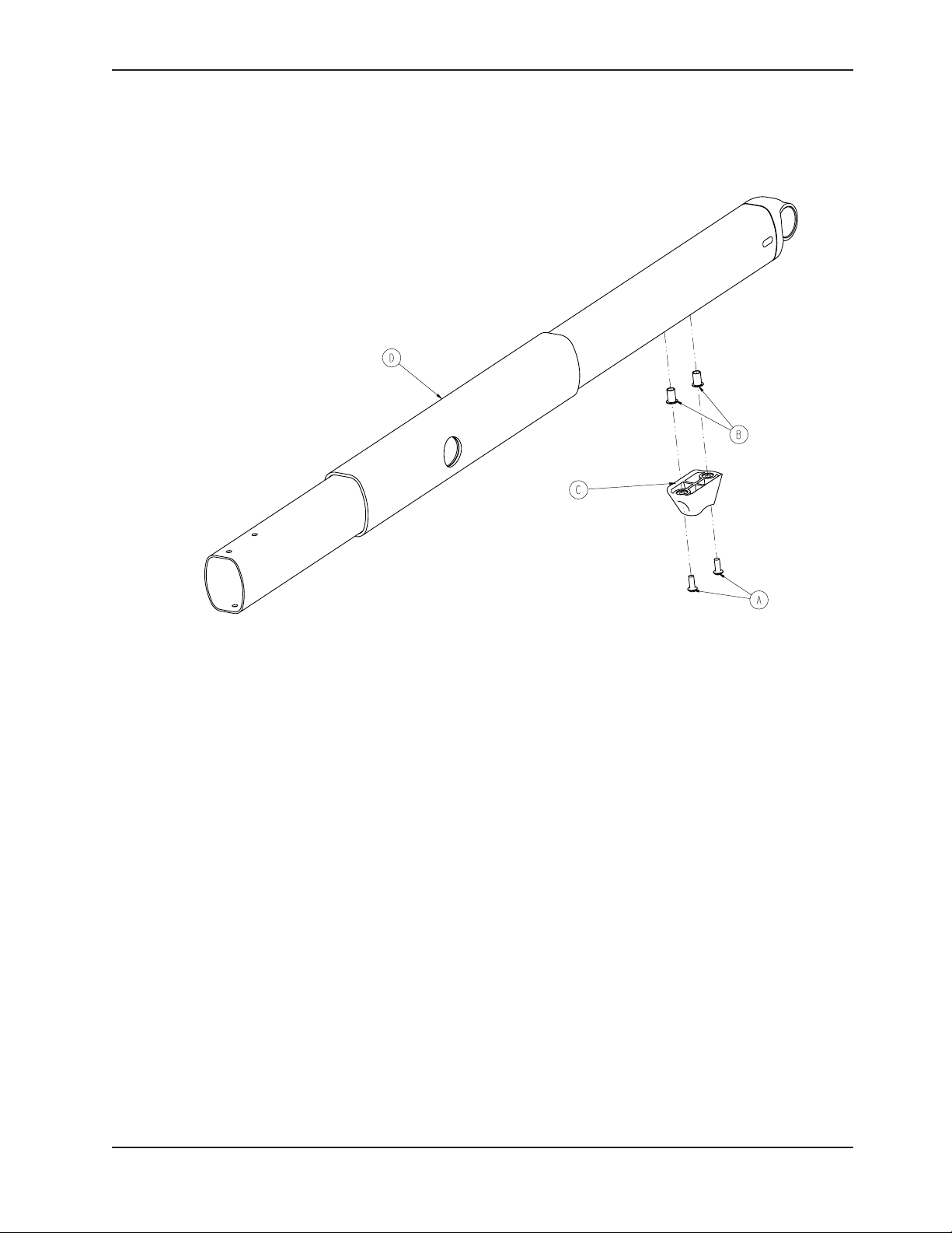
Inner Lift Tube Assembly, Litter Pivot, Right - 6550-001-034
Rev C
Item Part No. Part Name Qty.
A 0004-634-000 Button Head Cap Screw 2
B 0055-100-075 Riv Nut 2
C 6500-001-125 Base Dead Stop 1
D 6550-001-260 Litter Pivot Inner Lift Tube Weldment 1
Return To Table of Contents
www.stryker.com 6550- 30 9- 001 REV A 91
Page 92
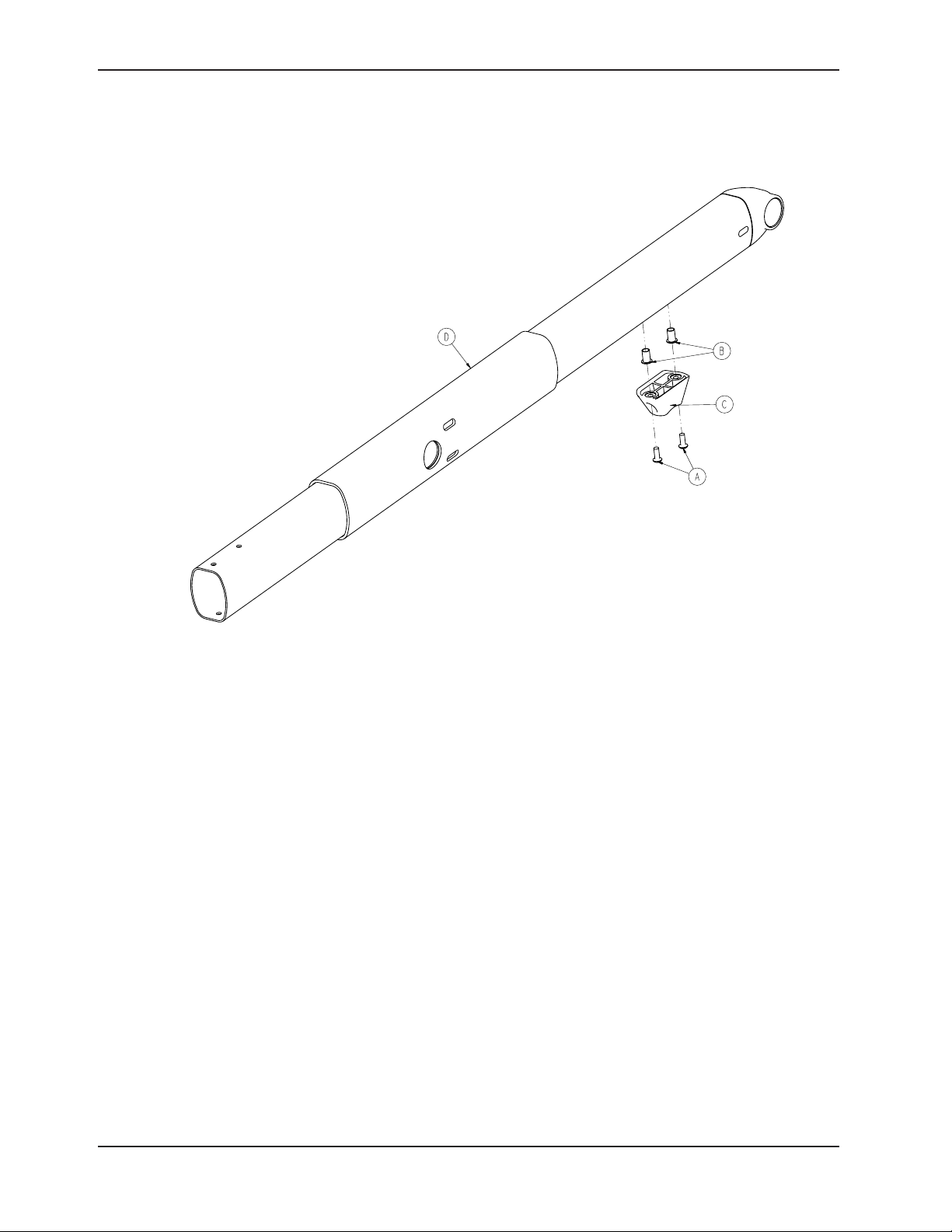
Inner Lift Tube Assembly, Litter Pivot, Left - 6550-001-035
Rev C
Item Part No. Part Name Qty.
A 0004-634-000 Button Head Cap Screw 2
B 0055-100-075 Riv Nut 2
C 6500-001-125 Base Dead Stop 1
D 6550-101-058 Litter Pivot Inner Lift Tube Weldment 1
Return To Table of Contents
92 655 0- 30 9-0 01 REV A w ww.stryker.com
Page 93

Caster, Steer Lock, Wheel Lock Assembly
6550-001-016 Rev B (Reference Only)
Note: Item H can be rotated incrementally in the counter clockwise direction to increase locking force.
Item Part No. Part Name Qty.
A 0004-098-000 Button Head Cap Screw 1
B 0011-454-000 Washer 2
C 0011-456-000 Washer 1
D 0016-118-000 Hex Lock Nut 1
E 0025-079-000 Rivet 2
F 6080-100-032 Spring 1
G 6080-300-030 Adjustable Caster Lock Pedal 1
H 6080-200-041 Adj Caster Lock Octagonal Sleeve 1
J 6550-001-050 Caster Horn, Foot End 1
Return To Table of Contents
www.stryker.com 6550- 30 9- 001 REV A 93
Page 94

Hitch Assembly, Head End
6550-001-021 Rev B (Reference Only)
Return To Table of Contents
94 655 0-309-0 01 REV A w ww.stryker.com
Page 95

Hitch Assembly, Head End
Return To Table of Contents
www.stryker.com 6550- 30 9- 001 REV A 95
Page 96

Hitch Assembly, Head End
Hitch Assembly, Head End - 6550-001-021 Rev B (Reference Only)
Item Part No. Part Name Qty.
A 0003-391-000 Hex Head Cap Screw 2
B 0004-376-000 Button Head Cap Screw 2
C 0004-634-000 Button Head Cap Screw 8
D 0016-028-000 Fiberlock Hex Nut 2
E 0025-133-000 Rivet 2
F 0026-385-000 Clevis Pin 1
G 0038-588-000 Extension Spring 1
H 0055-100-075 Riv Nut 4
J 0056-016-000 Bumper 2
K 0081-012-002 Flange Bearing 2
L 6550-001-054 Crash Connect Center Weldment 1
M 6550-001-055 Case Weldment Hitch, Head End 1
N 6550-001-059 Crash Connect Center Wldmnt, Left 1
P 6550-001-063 Crash Connect Center Wldmnt, Right 1
R 6550-001-083 Label, Hitch Pinch Point, Head End 1
T 6550-001-087 Hitch Wear Strip, Head End 1
U 6550-001-134 Hitch Bar, Head End 1
V 6550-001-140 Hitch Bar Sleeve, Head End 1
W 6550-001-174 Hitch Cover, Head End 1
Y 6550-001-175 Hitch Guide, Head End 2
Return To Table of Contents
96 6550 -309 - 001 REV A ww w.stryker.com
Page 97

6550-101-032 Rev A (Reference Only)
Outer Rail, Right
Item Part No. Part Name Qty.
A 0004-589-000 Button Head Cap Screw 1
B 0004-591-000 Socket Head Cap Screw 12
C 0004-612-000 Button Head Cap Screw 2
D 0004-613-000 Socket Head Cap Screw 2
E 0016-102-000 Nylock Nut 2
F 0055-100-076 Riv Nut 5
G 6500-001-029 Empty Sensor Housing 1
H 6500-001-102 Base/Litter Interface Bracket 2
J 6500-001-104 Litter Support Bracket, Outside 2
K 6500-001-106 Litter Support Bracket, Inside 2
L 6500-001-116 Siderail Bracket 3
M 6500-001-117 Siderail Clamp 2
N 6550-101-064 Outer Rail Weldment, Right 1
P 6550-001-096 Outer Rail Clamp 1
R 6550-001-166 Dead Stop 1
Return To Table of Contents
www.stryker.com 6550- 30 9- 001 REV A 97
Page 98

6550-101-033 Rev A (Reference Only)
Outer Rail, Left
Item Part No. Part Name Qty.
A 0004-589-000 Button Head Cap Screw 1
B 0004-591-000 Socket Head Cap Screw 12
C 0004-612-000 Button Head Cap Screw 2
D 0004-613-000 Socket Head Cap Screw 2
E 0016-102-000 Nylock Hex Nut 2
F 0055-100-076 Riv Nut 5
G 6500-001-029 Empty Sensor Housing 1
H 6500-001-102 Base/Litter Interface Bracket 2
J 6500-001-104 Litter Support Bracket, Outside 2
K 6500-001-106 Litter Support Bracket, Inside 2
L 6500-001-116 Siderail Bracket 3
M 6500-001-117 Siderail Clamp 2
N 6550-101-065 Outer Rail Weldment, Left 1
P 6550-001-096 Outer Rail Clamp 1
R 6550-001-166 Dead Stop 1
T 0055-100-075 Riv Nut 1
Return To Table of Contents
98 6550 - 309- 001 REV A ww w.stryker.com
Page 99
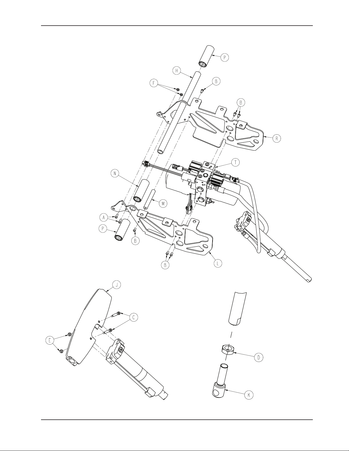
Mounted Hydraulics Assembly
6550-001-031 Rev A (Reference Only)
Return To Table of Contents
www.stryker.com 6550- 30 9- 001 REV A 99
Page 100

Mounted Hydraulics Assembly
Mounted Hydraulics Assembly - 6550-001-031 Rev A (Reference Only)
Item Part No. Part Name Qty.
A 0004-577-000 Button Head Cap Screw 2
B 0004-589-000 Button Head Cap Screw 6
C 0008-030-000 Socket Head Shoulder Screw 2
D 0015-052-000 Hex Jam Nut 1
E 0016-002-000 Fiberlock Hex Nut 2
F 0016-102-000 Nylock Hex Nut 2
G 0055-100-074 Well Nut 6
H 6500-001-105 Cross Tube, Litter Support 1
J 6500-001-164 Pivot, Cylinder Mount, Top 1
K 6500-001-169 Rod End, Cylinder 1
L 6500-001-194 Motor Mount 1
M 6500-001-212 Cross Bar, Motor Mount 1
N 6500-001-249 Plastic Extrusion, Spacer 1
P 6500-001-250 Plastic Extrusion, Spacer 2
R 6500-001-294 Motor Mount 1
T 6550-001-030 Hydraulics Assembly 1
Return To Table of Contents
100 6550 - 309- 001 R EV A ww w.stryker.com
 Loading...