

Page 1
Performance-PRO™ XT
REF
Model 6086
Operations/Maintenance Manual
For parts or technical assistance:
USA: 1-800-327-0770
2012/05 B.0 6086-009-001 REV B www.stryker.com
Page 2

Page 3

Table of Contents
Symbols and Definitions ....................................................................7
Symbols ............................................................................7
Warning/Caution/Note Definition ...........................................................7
Introduction .............................................................................8
Product Description ....................................................................8
Intended Use of Product.................................................................8
Specifications ........................................................................9
Contact Information ...................................................................10
Serial Number Location ................................................................10
Product Illustration....................................................................11
Summary of Safety Precautions .............................................................12
Setup Procedures........................................................................16
Cot Fastener Installation ...................................................................17
Vehicle Safety Hook Selection ..............................................................19
Vehicle Safety Hook Installation .............................................................20
Vehicle Configuration..................................................................20
Required Hardware for Installation of the Safety Hook (Not Supplied) ..............................20
Front to Back Positioning of the Safety Hook ................................................21
Side to Side Positioning of the Safety Hook .................................................22
Installing the Safety Hook...............................................................22
Adjusting Cot Load Height..................................................................23
Cot Positions ...........................................................................24
Operation Guide.........................................................................25
Operating Guidelines ..................................................................25
Proper Lifting Techniques...............................................................25
Transferring the Patient to the Cot ........................................................26
Rolling the Cot .......................................................................26
Adjusting the Height of the Cot with Two Operators............................................27
Adjusting the Height of an Empty Cot with One Operator........................................28
Loading or Unloading the Cot ............................................................29
Loading or Unloading the Cot with the Power-LOAD Option ......................................29
Loading the Cot into a Vehicle with Two Operators ............................................30
Loading an Empty Cot into a Vehicle with One Operator ........................................31
Unloading the Cot from a Vehicle with Two Operators ..........................................32
Unloading an Empty Cot from a Vehicle with One Operator ......................................33
Using Additional Assistance .............................................................34
Operating the Siderails.................................................................35
Operating the Backrest ................................................................35
Operating the Retractable Head Section....................................................36
Adjusting the Footrest .................................................................37
Adjusting the Optional Knee Gatch ........................................................38
Operating the Optional Wheel Locks ......................................................39
Using Restraint Straps .................................................................40
Using the Restraint Belt Extension ........................................................43
www.stryker.com 6086-009 -001 REV B 3
Page 4

Table of Contents
Optional Accessories .....................................................................44
Installing the Base Storage Net ..........................................................45
Using the Defibrillator Platform ...........................................................45
Using the Equipment Hook ..............................................................46
Using the Head Extension with Pillow ......................................................46
Operating the Optional Two-Stage I.V. Pole..................................................47
Operating the Optional Three-Stage I.V. Pole ................................................48
Using the Kickstand for Dialysis Scale .....................................................49
Attaching an Oxygen Bottle to an Oxygen Bottle Holder ........................................50
Using the Retractable Head Section Oxygen Bottle Holder ......................................51
Attaching the Pedi-Mate® Infant Restraint System ............................................52
Installing the Backrest Storage Pouch......................................................54
Installing the Head End Storage Flat .......................................................55
Using the Transfer Flat.................................................................55
Cleaning...............................................................................56
Washing Procedure ...................................................................56
Washing Limitations ...................................................................56
Removal of Iodine Compounds...........................................................57
Preventative Maintenance ..................................................................58
Checklist ...........................................................................58
Regular Inspection and Adjustments .......................................................59
Maintenance Record......................................................................61
Training Record .........................................................................62
Quick Reference Replacement Parts List ......................................................63
Service Information.......................................................................64
Backrest Adjustment ..................................................................64
Wheel Locking Force Adjustment .........................................................65
Cot Retaining Post Adjustment ...........................................................66
Cot Retaining Post Replacement .........................................................67
Cot Retaining Post Screw Replacement ....................................................67
Headsection Replacement ..............................................................68
Backrest Gas Cylinder Replacement.......................................................68
Inner, Inner Tube Replacement ...........................................................69
Outer, Inner Tube Replacement ..........................................................70
Outer, Outer Tube Replacement ..........................................................71
Inner, Outer Tube Replacement ..........................................................72
Siderail Assembly Replacement ..........................................................73
Cot Assembly ...........................................................................74
Base Assembly..........................................................................78
No Steer Lock Option .....................................................................82
No Wheel Lock Option ....................................................................83
Single Wheel Lock Option..................................................................84
Dual Wheel Lock Option ...................................................................85
Caster Horn Assembly ....................................................................86
4 6086-009 -001 REV B www.stryker.com
Page 5

Table of Contents
Adjustable Caster Lock Assembly ............................................................87
Wheel Assembly - 6060-002-010 ............................................................88
Cot Retaining Post, Right - 6085-033-000 ......................................................89
Optional Dual Cot Retaining Post - 6085-034-000 ................................................90
Kickstand Assembly - 6085-002-000..........................................................91
Kickstand Sub-Assembly - 6085-002-016 ......................................................92
Inner Leg Assembly - 6085-001-017 ..........................................................93
Outer Lift Tube Assembly, Litter Pivot, Right ....................................................94
Outer Lift Tube Assembly, Litter Pivot, Left .....................................................95
Litter Base Assembly .....................................................................96
Lock Bar Assembly - 6085-001-013...........................................................97
Siderail Option ..........................................................................98
Siderail Assembly - 6082-026-010............................................................99
Outer Rail Subassembly, Right .............................................................100
Outer Rail Subassembly, Left ..............................................................101
Foot End Assembly, Left ..................................................................102
Optional Foot End Assembly, Right ..........................................................104
Retractable Head Section .................................................................106
Head Section Assembly - 6500-002-023 ......................................................107
Telescoping Tube Assembly - 6500-002-024 ...................................................109
Head Section Lock Assembly - 6500-001-026 ..................................................110
Left Hand Release Handle ................................................................111
Optional Right Hand Release Handle.........................................................1 13
Slide Housing Assembly, Left ..............................................................1 15
Slide Housing Assembly, Right .............................................................116
Fowler Assembly .......................................................................1 17
Non-Power-LOAD Compatible Option.........................................................1 18
Headsection - 6500-002-020 ..............................................................12 0
Optional In-Fastener Shut-Off Assembly - 6500-001-027 ..........................................12 2
No Headsection Oxygen Bottle Holder Option - 6506-036-000 ......................................12 3
Power-LOAD Compatible Option - 6086-055-000................................................12 4
Foot End Fastener Assembly (Power-LOAD Compatible Option) ..................................... 12 6
EMS Restraint Package - 6500-002-030 ......................................................12 8
Trend - 6085-031-000....................................................................12 9
Optional Gatch - 6085-032-000 ............................................................13 0
Optional Gatch Assembly .................................................................131
Optional Gatch Support Assembly........................................................... 13 4
Optional Accessories ....................................................................13 5
Defibrillator Platform - 6500-170-000......................................................... 13 6
Equipment Hook - 6500-147-000 ............................................................13 7
Head Extension - 6100-044-000 ............................................................13 8
Head Extension Assembly - 6100-044-012 ....................................................13 9
Two-Stage I.V. Pole Assembly, Right - 6500-210-000 .............................................140
Three-Stage I.V. Pole Assembly, Right - 6500-215-000............................................140
www.stryker.com 6086-009 -001 REV B 5
Page 6

Table of Contents
Two-Stage I.V. Pole Assembly, Right - 6500-001-041 .............................................141
Three-Stage I.V. Pole Assembly, Right - 6500-001-043 ...........................................142
Two-Stage I.V. Pole Assembly, Left - 6500-211-000 ..............................................143
Three-Stage I.V. Pole Assembly, Left - 6500-216-000 ............................................14 3
Two-Stage I.V. Pole Assembly, Left - 6500-001-042 ..............................................144
Three-Stage I.V. Pole Assembly, Left - 6500-001-044 ............................................145
Optional Two-Stage I.V. Pole Assembly, Dual - 6500-212-000.......................................146
Optional Three-Stage I.V. Pole Assembly, Dual - 6500-217-000 .....................................146
Oxygen Bottle Holder, Foot End - 6500-140-000 ................................................147
Oxygen Bottle Holder Assembly - 6500-001-040 ................................................148
Oxygen Bottle Holder, Head End - 6500-141-000 ................................................149
Removable Oxygen Bottle Holder - 6080-140-000 ...............................................15 0
Retractable Head Section Oxygen Bottle Holder - 6085-046-000 ....................................151
Backrest Pouch - 6500-130-000 ............................................................15 2
Head End Storage Flat - 6500-128-000 .......................................................153
Transfer Flat - 6005-001-001 ..............................................................15 4
Warranty .............................................................................15 5
Stryker EMS Return Policy .............................................................156
Return Authorization.................................................................. 15 6
Damaged Merchandise ...............................................................15 6
International Warranty Clause...........................................................156
Patent Information ...................................................................156
6 6086-009 -001 REV B www.stryker.com
Page 7
Symbols and Definitions
SYMBOLS
Attention, consult accompanying documents
Safe Working Load Symbol
Pinch Point
WARNING/CAUTION/NOTE DEFINITION
The words WARNING, CAUTION and NOTE carry special meanings and should be carefully reviewed.
WARNING
Alerts the reader about a situation which, if not avoided, could result in death or serious injury. It may also describe
potential serious adverse reactions and safety hazards.
CAUTION
Alerts the reader of a potentially hazardous situation which, if not avoided, may result in minor or moderate injury to the
user or patient or damage to the equipment or other property. This includes special care necessary for the safe and
effective use of the device and the care necessary to avoid damage to a device that may occur as a result of use or
misuse.
NOTE
Provides special information to make maintenance easier or important instructions clearer.
Return To Table of Contents
www.stryker.com 6086-009 -001 REV B 7
Page 8

Introduction
This manual is designed to assist you with the operation and maintenance of the Stryker Performance-PRO™ XT cot.
Read this manual thoroughly before using the equipment or beginning maintenance on it. To ensure safe operation of
this equipment, it is recommended that methods and procedures be established for educating and training staff on the
safe operation of this cot.
PRODUCT DESCRIPTION
The Stryker Model 6086 Performance-PRO™ XT is a manual ambulance cot that consists of a platform mounted on
a wheeled X-frame designed to support and transport a maximum weight of 700 pounds in pre-hospital and hospital
environments. The device is collapsible for use in emergency vehicles and has an adjustable load height feature to
allow the device to be set to different ambulance deck heights for proper body mechanics during loading and unloading. Duplicate foot-end controls on the upper and lower lift bars accommodate different operator positions or sizes and
the side release handle allows a single operator to raise and lower an unoccupied cot. The device is equipped with
the following: a retractable head section for 360-degree mobility in any height position, side rails, patient securement
straps, an adjustable pneumatic backrest and various optional accessories that assist with transport of the patient.
Maximum patient comfort is attainable with the three different litter positions of shock, flat leg and optional knee gatch
positioning.
INTENDED USE OF PRODUCT
The Stryker Model 6086 Performance-PRO™ XT is a non-powered wheeled stretcher, which is intended to support and
transport the entire body of a traumatized, ambulatory or non-ambulatory human patient (includes infants and adults).
The device is designed to support patients in a supine (horizontal) or sitting position and facilitate the transportation
of associated medical equipment (i.e. oxygen bottles, monitors, and/or pumps) in emergency/transport vehicles. This
ambulance cot is intended to be used in pre-hospital and hospital environments, in emergency and non-emergency
applications. It is rated to a maximum capacity of 700 pounds (sum of the patient, mattress and accessory weight) and
the intended operators of the device are trained professionals including: emergency medical service and medical care
center personnel, as well as medical first responders. The expected service life of the product is 7 years.
Ambulance cots are intended for transportation purposes. They are not intended for extended stay or to be used
as hospital beds. They are also not intended to be used in devices which modify air pressure, such as hyperbaric
chambers.
Return To Table of Contents
8 6086-009 -001 REV B www.stryker.com
Page 9

Introduction
SPECIFICATIONS
Safe Working Load
Note: Safe Working Load indicates the sum of
the patient mattress and accessory weight.
Backrest Articulation/Shock Position 0° to 73° / +15°
Overall Length/Minimum Length/Width 80" / 64" / 23" 203,2 cm / 162,6 cm / 58,4 cm
1
Height
Position 1 13. 8” 35 ,1 c m
Position 2 22” 55,9 cm
Position 3 25.8” 65,5 cm
Position 4 28.1” 71,4 c m
Position 5 31.9” 81 cm
Position 6 34.6” 87,9 c m
Position 7 (LOW) 37. 3 ” 94,7 cm
Position 8 (MID) 40” 101,6 cm
Position 9 (HIGH) 42.2” 107, 2 cm
2
Weight
Caster Diameter/Width 6" / 2" 15,2 cm / 5,1 cm
Minimum Operators Required for an Occupied Cot 2
Minimum Operators Required for an Unoccupied Cot 1
Recommended Fastener Systems Model 6370 or 6377 Floor Mount Type
Maximum Loading Height
3
Single Wheel Lock / Double Wheel Lock Optional
700 pounds 317, 5 k g
89 lb 40,37 kg
Model 6371 Wall Mount Type
Up to 34" Up to 86,4 cm
1
Height is measured from the bottom of the mattress at seat section to ground level.
2
Cot is weighed without mattress and restraints.
3
Load wheel height can be set between 27.25” (69,2 cm) and 34” (86,4).
Stryker reserves the right to change specifications without notice.
The Performance-PRO™ XT is designed to conform to the Federal Specification for the Star-of-Life Ambulance (KKK-A-1822).
The Performance-PRO™ XT is designed to be compatible with competitive cot fastener systems.
Patents pending.
The yellow and black color scheme is a proprietary trademark of Stryker Corporation.
Return To Table of Contents
www.stryker.com 6086-009 -001 REV B 9
Page 10
Introduction
CONTACT INFORMATION
Contact Stryker Customer Service or Technical Support at: (800) 327-0770 or (269) 324-6500.
Stryker Medical
3800 E. Centre Avenue
Portage, MI 49002
USA
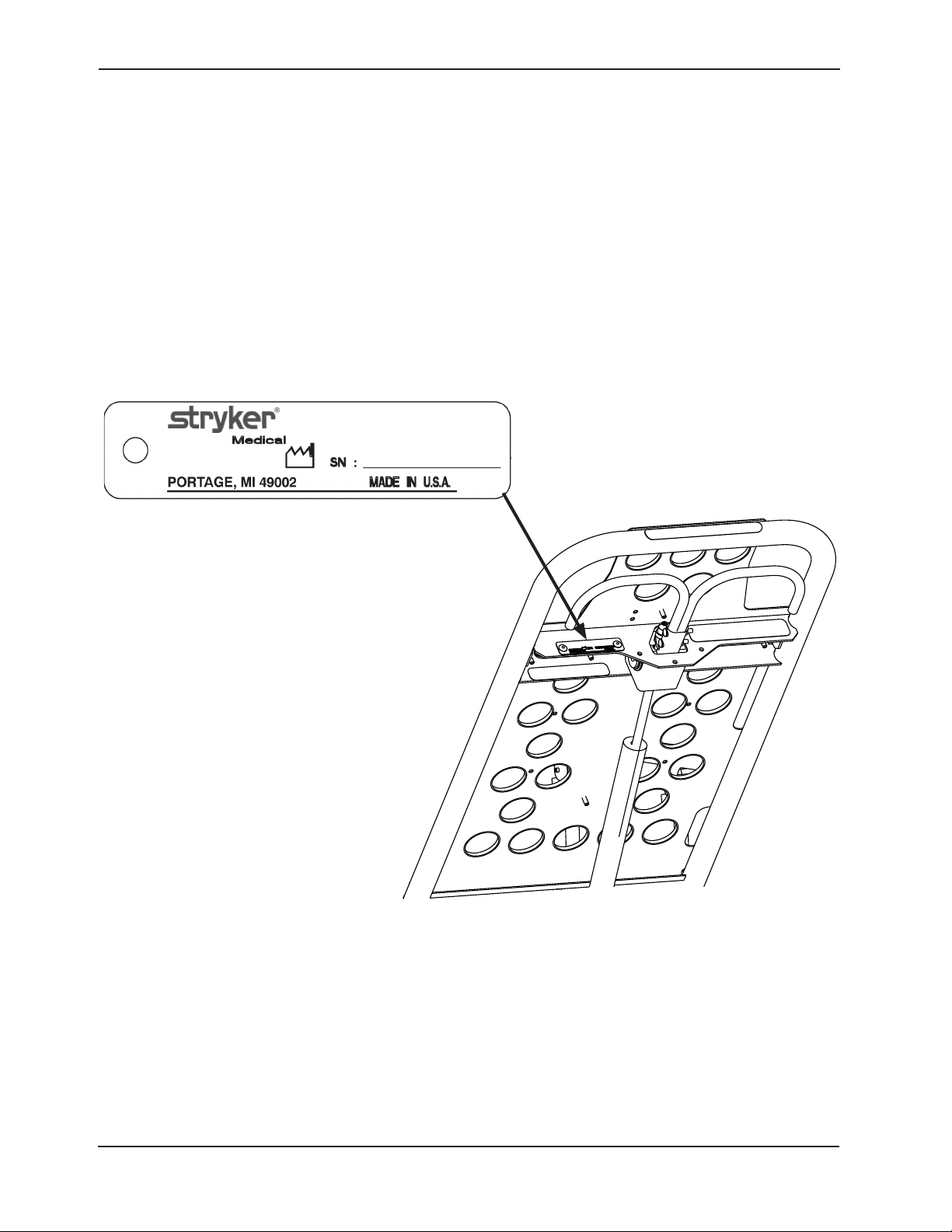
SERIAL NUMBER LOCATION
Please have the serial number (Figure 1) of your Stryker product available when calling Stryker Customer Service or
Technical Support. Include the serial number in all written communication.
Head End
Figure 1: Cot Serial Number & Location
Return To Table of Contents
10 6086-009 -001 REV B www.stryker.com
Page 11
Introduction
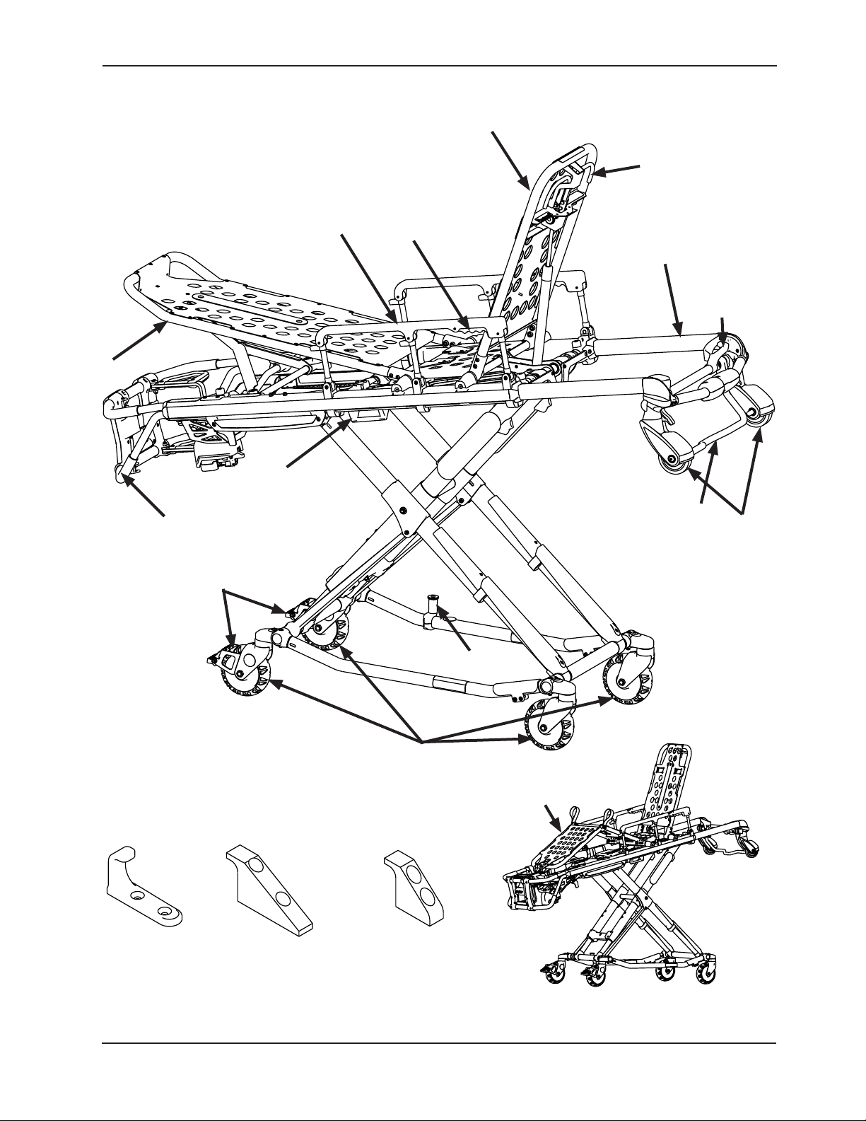
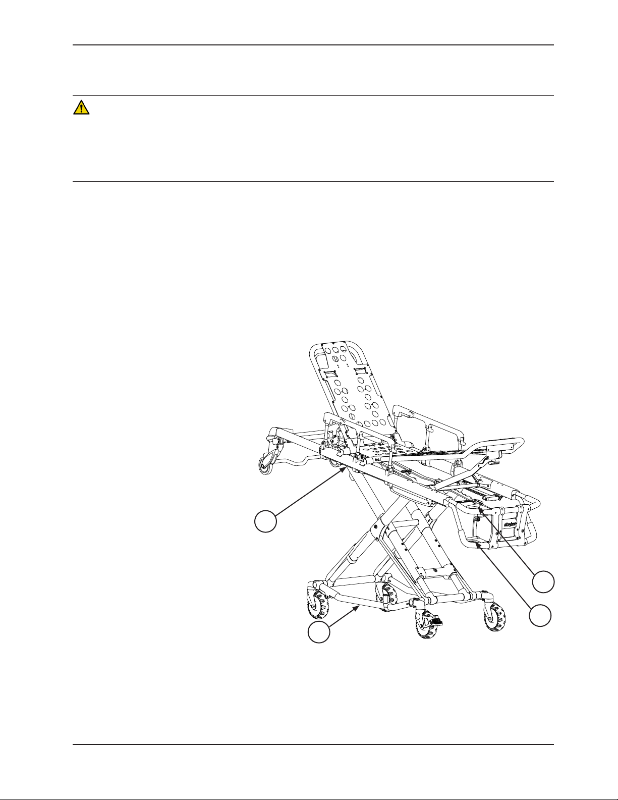
PRODUCT ILLUSTRATION
Foot Rest
Foot End
Release Handle
Side Release
Handle
Siderail
Siderail Release
Backrest
Head End
Backrest
Adjustment
Handle
Retractable
Head Section
Head Section
Release
Safety Bar
Loading
Wheels
Wheel Lock
(Optional)
Foot End
J Safety Hook
Stryker part number
6092-036-018
Long Safety Hook
Stryker part number
6060-036-018
Cot Retaining Post
Transport Wheels
Knee Gatch
(Optional))
Short Safety Hook
Stryker part number
6060-036-017
Figure 2: Cot Components
Return To Table of Contents
www.stryker.com 6086-009 -001 REV B 11
Page 12

Summary of Safety Precautions
Carefully read and strictly follow the warnings and cautions listed on this page. Service only by qualified personnel.
WARNING
• Ensure proper hand placement on hand grips. Hands should be clear of red safety bar pivots while loading and
unloading the cot or whenever changing height position of the cot with two or more operators.
• Improper usage of the cot can cause injury to the patient or operator. Operate the cot only as described in this
manual.
• Do not modify the cot or any components of the cot. Modifying the product can cause unpredictable operation
resulting in injury to the patient or operator. Modifying the product also voids its warranty (see page 155).
• It is the responsibility of the cot operator to ensure that the cot being used in the Stryker Cot Fastener system
meets the installation specifications listed on page 18. Injury may result if a non-compatible cot is used in the
Stryker Cot Fastener system.
• Have the vehicle safety hook installed by a certified mechanic. Improper safety hook installation can cause injury
to the patient or operator and/or damage to the cot.
• Failure to install the safety hook can cause injury to the patient or operator. Install and use the safety hook as
described on page 19.
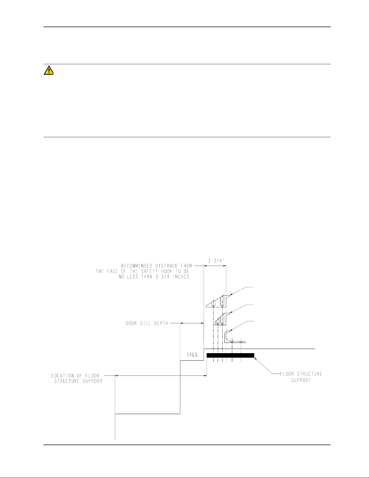
• The face of the safety hook that engages the safety bar should be located at least 3-3/4” from the leading edge
of the door sill. After installation, verify that the cot legs lock into the load position without contacting the vehicle
bumper.
• To avoid injury, verify that the safety bar has engaged the safety hook before removing the cot from the patient
compartment.
• Verify that the safety hook always engages the cot safety bar regardless of how the cot is unloaded from the
vehicle or injury to the patient or operator and/or damage to the cot may occur.
• The cot must have at least 5/8” of clearance between the vehicle bumper and the cot to disengage the safety bar
when unloading the cot from the vehicle. Verify that the cot legs lock into the load position before disengaging the
safety bar from the safety hook. Failure to properly lock the cot height into position can cause injury to the patient
or operator and/or damage to the cot.
• Before placing the cot into service, confirm that the cot load height is set correctly for your vehicle.
• Practice changing height positions and loading the cot until operation of the product is fully understood. Improper
use can cause injury.
• Do not allow untrained assistants to assist in the operation of the cot. Untrained technicians/assistants can cause
injury to the patient or themselves.
• Do not ride on the base of the cot. Damage to the product could occur, resulting in injury to the patient or operator.
• Transporting the cot sideways can cause the cot to tip, resulting in possible damage to the product and/or injury to the
patient or operator. Transporting the cot in a lowered position, head or foot end first, minimizes the potential of a cot tip.
• Grasping the cot improperly can cause injury. Keep hands, fingers and feet away from moving parts. To avoid
injury, use extreme caution when placing your hands and feet near the base tubes while raising and lowering the
cot.
• Always use all restraint straps to secure the patient on the cot. An unrestrained patient may fall from the cot and
be injured.
• Never leave a patient unattended on the cot or injury could result. Hold the cot securely while a patient is on the
product.
• Never apply the optional wheel locks while a patient is on the cot. Tipping could occur if the cot is moved while
the wheel lock is applied, resulting in injury to the patient or operator and/or damage to the cot.
• Siderails are not intended to serve as a patient restraint device. See page 40 for proper restraint strap usage.
Failure to use the restraint straps properly could result in patient injury.
• High obstacles such as curbing, steps or rough terrain can cause the cot to tip, possibly causing injury to the
patient or operator.
• If the cot is equipped with the optional kickstand, make sure that the kickstand remains in the retracted position and
does not engage during transport.
Return To Table of Contents
12 6086-009-001 REV B www.stryker.com
Page 13

Summary of Safety Precautions
WARNING
• Transporting the cot in lower positions reduces the potential of a cot tip. If possible, obtain additional assistance
or take an alternate route.
• When operating the side release handle, keep hands away from the foot end release handle to avoid injury.
• If lowering the cot to the lowest position (position 1), remove your foot from the base tube or injury could result.
• Power-LOAD is designed to be compatible with the 6085/6086 Performance-PRO XT, 6500/6506 Power-PRO XT,
and 6510/6516 Power-PRO IT cots with the Power-LOAD option only. In certain situations, you can use PowerLOAD as a standard antler for most X-frame cots, but a rail clamp assembly is required for all cots without the
Power-LOAD option.
• It is the responsibility of the cot operator to ensure that the cot being used in the Stryker Model 6390 Power-LOAD
system is a Power-LOAD compatible cot. Injury may result if a non-compatible cot is used in the Stryker Model
6390 Power-LOAD system.
• Two operators must be present when the cot is occupied.
• Operators must be able to lift the total weight of the patient, cot and any items on the cot.
• The higher an operator must lift the cot, the more difficult it becomes to hold the weight. An operator may need
help loading the cot if he/she is too short or if the patient is too heavy to lift safely. The operator must be able to
lift the cot high enough for the cot legs to unfold completely and lock when the cot is unloaded. A shorter operator
needs to raise their arms higher to enable the undercarriage to unfold.
• There must be a safety hook properly installed in the vehicle so that the bumper does not interfere with the front
legs of the base frame.
• The one person loading and unloading procedures are for use only with an empty cot. Do not use the procedures
when loading/unloading a patient. Injury to the patient or operator could result.
• Do not pull or lift on the safety bar when unloading the cot. Damage to the safety bar could result and injury to
the patient or operator could occur.
• To avoid injury, always verify that the head section is locked into place prior to operating the cot.
• Be sure that the undercarriage has engaged and is locked before removing the loading wheels from the patient
compartment floor of the vehicle. An unlocked undercarriage will not support the cot and injury to the patient or
operator could result.
• Siderails are not intended to serve as a patient restraint device. See page 40 for proper restraint strap usage.
Failure to utilize the siderails properly could result in patient injury.
• Do not attempt to load the cot into the patient compartment with the head section retracted. Loading the cot
with the head section retracted may cause the product to tip or not engage properly in the cot fastener, possibly
causing injury to the patient or operator and/or damage to the product.
• Never install or use wheel locks on a cot with excessively worn wheels. Installing or using wheel locks on wheels
with less than a 6” diameter could compromise the holding ability of the wheel lock, resulting in injury to the patient
or operator and/or damage to the cot or other equipment.
• Do not attach restraints to the base tubes, cross tubes, or fowler skin. Improper restraint attachment could result
in damage to the cot further resulting in injury to the patient or operator.
• Stryker recommends a two person operation when using the kickstand.
• Make sure that the patient weight is centered on the cot before using the kickstand.
• Engage the kickstand with your foot only.
• Lower cot height prior to engaging kickstand for increased stability.
• Make sure that the kickstand remains in the retracted position and does not engage during transport.
• Do not use the kickstand as a brake.
• Do not engage kickstand on a sloped surface.
• If the cot is equipped with the optional retractable head section oxygen bottle holder, use caution while the oxygen
bottle holder is installed to avoid pinching your fingers between the fowler bracket and the oxygen bottle.
• To avoid accidental release of the Pedi-Mate® and possible injury to the infant, ensure that the buckle is located
away from obstructions on the cot or accessories.
• When the optional head end storage flat is being used, ensure that it does not interfere with the operation of the
retractable head section, safety bar and safety hook. Injury to the patient or operator could result.
Return To Table of Contents
www.stryker.com 6086-009 -001 REV B 13
Page 14

Summary of Safety Precautions
WARNING
• When cleaning, use any appropriate personal safety equipment (goggles, respirator, etc.) to avoid the risk of
inhaling contagion. Use of power washing equipment can aerate contamination collected during the use of the cot.
• SOME CLEANING PRODUCTS ARE CORROSIVE IN NATURE AND MAY CAUSE DAMAGE TO THE PRODUCT IF
USED IMPROPERLY. If the products described above are used to clean Stryker patient care equipment, measures
must be taken to ensure that the cots are wiped with clean water and thoroughly dried following cleaning. Failure
to properly rinse and dry the cots leaves a corrosive residue on the surface of the cots, possibly causing premature
corrosion of critical components.
• Failure to properly clean or dispose of contaminated mattress or cot components increases the risk of exposure to
bloodborne pathogens and may cause injury to the patient or the operator.
CAUTION
• Set the cot load height to the proper stop height prior to operation.
• Installation of the safety hook should be done by a certified mechanic familiar with ambulance vehicle construction.
Consult the vehicle manufacturer before installing the safety hook and be sure that the installation of the safety
hook does not damage or interfere with the brake lines, oxygen lines, fuel lines, fuel tank or electrical wiring of
the vehicle.
• Before operating the cot, clear any obstacles that may interfere and cause injury to the operator or patient.
• Do not allow the cot undercarriage to drop unassisted (commonly known as a “hot drop”) when removing the cot
from the vehicle. Repeated hot dropping causes premature wear or damage to the cot.
• Wheel locks are only intended to help prevent the cot from rolling while unattended. Wheel locks may not provide
sufficient resistance on all surfaces or under loads.
• Ensure that the restraints are not entangled in the base frame when raising and lowering the cot.
• The weight of the equipment in the base storage net (if equipped) must not exceed 20 lb (9 kg).
• Be careful when retracting the base to avoid damaging items stored in the base storage net.
• To avoid damage to the equipment hook, the weight of the accessories or equipment must not exceed 35 lb
(15. 9 kg).
• To avoid damage to the I.V. pole, the weight of the I.V. bags or equipment must not exceed 40 lb (18 kg).
• To avoid damage to the oxygen bottle holder (if equipped), the weight of the equipment must not exceed 40 lb (18
kg).
• Do not use two head end oxygen bottle holders at the same time.
• Do not store items under the cot mattress. Storing items under the mattress can interfere with the operation of
the cot.
• The weight of the equipment in the pocketed backrest storage pouch (if equipped) must not exceed 20 lb (9 kg).
• The weight of the equipment in the head end storage flat (if equipped) must not exceed 40 lb (18 kg).
• DO NOT STEAM CLEAN OR ULTRASONICALLY CLEAN THE UNIT.
• Maximum water temperature should not exceed 180°F/82°C.
• Maximum water pressure should not exceed 1500 psi/130.5 bar. If a hand held wand is being used to wash the
unit, the pressure nozzle must be kept a minimum of 24 inches (61 cm) from the unit.
• Allow cot to air dry.
• Towel dry all casters and interface points.
• Failure to comply with these instructions may invalidate any/all warranties.
Return To Table of Contents
14 6086-009- 001 REV B www.stryker.com
Page 15
Summary of Safety Precautions
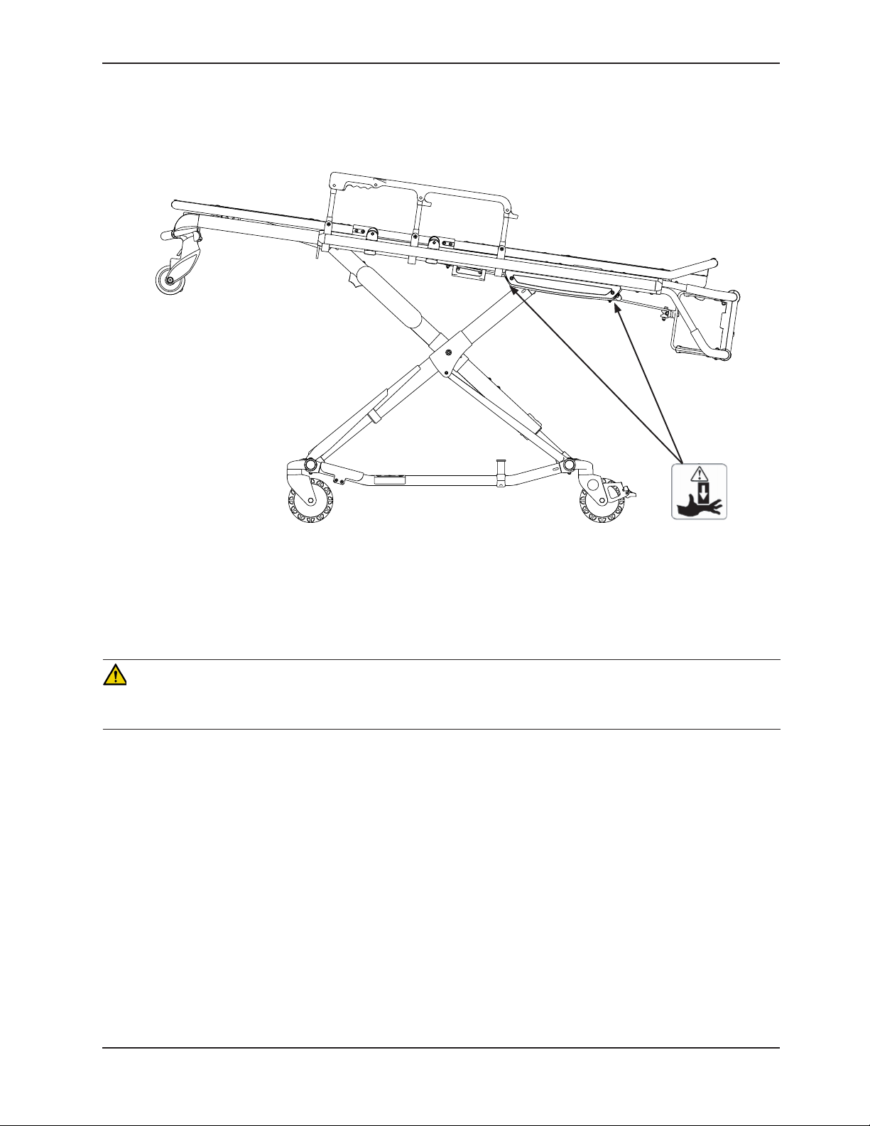
WARNING: Pinch Points
Figure 3: Potential Pinch Points
WARNING
Ensure proper hand placement on hand grips. Hands should be clear of red safety bar pivots while loading and unloading
the cot or whenever changing height position of the cot with two or more operators.
Return To Table of Contents
www.stryker.com 6086-009 -001 REV B 15
Page 16

Setup Procedures
Ensure that all shipping and packaging materials have been removed from the products prior to use.
Unpack the cartons and check all items for proper operation. It is important that the cot is working properly before it
is put into service. See “Figure 2: Cot Components” on page 11 to identify all of the cot components.
Before placing the cot into service, check these components:
• Check for loose fasteners. Replace if loose. Reference all assembly drawings.
• All welds are intact (not cracked or broken)
• No bent or broken tubing or sheet metal
• No debris in wheels
• All wheels are secure, and rolling and swivelling properly
• Both siderails move and latch properly
• Backrest operates properly
• Optional accessories are intact and operate properly
• Height positioning latch function operates properly
• Cot secure in each height position (see page 24)
• Undercarriage folds properly
• Retractable head section operates properly
• Safety bar operates properly
• Foot rest operates properly
• No rips or cracks in the mattress cover
• Body restraints are intact and operate properly
• Wheel locks operate properly (optional equipment)
• Vehicle safety hook engages the safety bar so that the cot loads and unloads properly from the vehicle (see page
19)
• Approved cot fastener (Stryker Model 6370/6377/6378/6379 or 6371 Cot Fastener − Not included) installed in the
vehicle (see page 17)
• Adjust cot load height (see page 23)
The patient compartment of the vehicle in which the cot will be used must have a:
• Smoothrearedgeforcotloading.
• Levelfloorlargeenoughforthefoldedcot.
• Stryker Model 6370/6377/6378/6379 or 6371 Cot Fastener System or Stryker Model 6390 Power-LOAD (not
included)
• 34” (86,4 cm) maximum loading height.
• Spacetoproperlyinstallthesafetyhook.
Note: Loose items or debris on the patient compartment floor can interfere with the operation of the safety hook and
cot fastener. Keep the patient compartment floor clear.
When necessary, modify the vehicle to fit the cot. Do not modify the cot.
WARNING
• Improper usage of the cot can cause injury to the patient or operator. Operate the cot only as described in this
manual.
• Do not modify the cot or any components of the cot. Modifying the product can cause unpredictable operation
resulting in injury to the patient or operator. Modifying the product also voids its warranty (see page 155).
Return To Table of Contents
16 6086-009-001 REV B www.stryker.com
Page 17

Cot Fastener Installation
Note: The Cot Fastener Installation instructions on page 17 through page 22 are intended for cots that you will
NOT use with Power-LOAD. For Model 6086 cots with the Power-LOAD option, see the Power-LOAD Operations/
Maintenance Manual for installation instructions.
The Stryker Cot Fastener Systems are designed to be compatible only with cots which conform to the installation
specifications listed on page 18.
WARNING
It is the responsibility of the cot operator to ensure that the cot being used in the Stryker Cot Fastener Systems meets the
installation specifications listed on page 18. Injury may result if a non-compatible cot is used in the Stryker Fastener
System.
Note: Adjustment of the rail clamp assembly may be required in order to compensate for any variation in the cot
retaining post position depending on the cot manufacturer and model number.
For more information about the Stryker Cot Fastener Systems, see the Cot Fastener Operations/Maintenance Manual.
Return To Table of Contents
www.stryker.com 6086-009 -001 REV B 17
Page 18
Cot Fastener Installation
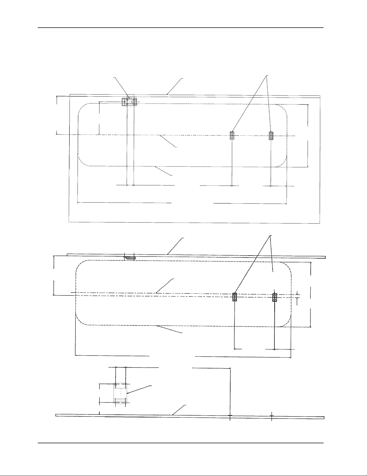
Note: These installation instructions are intended for cots that you will NOT use with Power-LOAD. For Model 6086
cots with the Power-LOAD option, see the Power-LOAD Operations/Maintenance Manual (6390-009-001) for installation
instructions.
RAIL SUPPORT BRACKET
14 5/8” (REF.)
(37,1 cm)
OR DESIRED
POSITION FROM
WALL
REAR OF
AMBULANCE
(REF.)
FLOOR PLATE
12 5/8”
WALL OF VEHICLE
(32 cm)
ANTLER FLOOR
PLATE S
COT
HEAD
END
COT CENTER LINE
COT PERIMETER
2 5/8”
(6,6 cm) (95,6 cm) (37,9 cm) (15,6 cm)
37 5/8”
14 15/16”
80” (REF.)
(203 cm)
Figure 4: Installation Specifications - Floor Mount Fastener
WALL OF VEHICLE
ANTLER FLOOR PLATES
24”
(REF.)
(61 cm)
6 1/8”
14 5/8”
(37,1 cm)
REAR OF
AMBULANCE
COT CENTER LINE
COT
HEAD
END
24” (REF.)
(61 cm)
1 1/8”
(2,9 cm)
(REF.)
COT PERIMETER
6 1/8”
3 5/8”
(9,2 cm)
80” (REF.)
(203 cm)
37 3/8”
(94,9 cm)
14 15/16”
(37,9 cm) (15,6 cm)
WALL MOUNTING BRACKET
(16,5 cm)
6 1/2”
FLOOR OF
4 5/16”
(10,9 cm)
VEHICLE
Figure 5: Installation Specifications - Wall Mount Fastener
Return To Table of Contents
18 6086-009-001 REV B www.stryker.com
Page 19
Vehicle Safety Hook Selection
Note: The Vehicle Safety Hook Selection and Installation instructions on page 19 through page 22 are intended for
cots that you will NOT use with Power-LOAD. For Model 6086 cots with the Power-LOAD option, see the Power-LOAD
Operations/Maintenance Manual for installation instructions. Power-LOAD ships and is installed with its own safety
hook, thus no additional hook is needed.
The vehicle safety hook is a device that ships with the cot. The cot safety bar and vehicle safety hook are designed
to keep the cot from being accidentally removed from the vehicle and to provide increased operator assurance and
confidence when loading and unloading. The safety hook was designed for compatibility and proper operation when
loading and unloading the cot from a vehicle that is compliant with Federal Regulation KKK-A-1822.
Stryker offers three different types of safety hooks
that are ordered and shipped with your cot. These
safety hook types are designed to meet the needs of
various emergency vehicle configurations, specifically
the length and location of the floor structure support
that is located in the rear of the vehicle.
Long Safety Hook
6060-036-018
Consider the following information when selecting
which safety hook is appropriate for your vehicle
Short Safety Hook
6060-036-017
configuration:
• Determine the location of the floor structure
J-Style Safety Hook
6092-036-018
support where there is adequate room to mount
the safety hook.
• Ensure that the safety hook can be securely
mounted into the back of the vehicle while
providing adequate bumper clearance to allow the
cot to be loaded and unloaded from the vehicle.
• Note the differences in vehicle design. Each safety
hook provides a different mounting location option
to maintain the appropriate distance between the
Figure 6: Safety Hook Types
face of the safety hook and the edge of the door sill.
Due to the differences in vehicle dimensions and the floor structure support locations, each safety hook requires a
different mounting location. See “Vehicle Safety Hook Installation” to determine the correct positioning for safety hook
installation.
Note: When replacing an existing safety hook with a new style, adjust the mounting location to maintain the proper
position of the safety hook face.
Return To Table of Contents
www.stryker.com 6086-009 -001 REV B 19
Page 20
Vehicle Safety Hook Installation
Note: These installation instructions are intended for cots that you will NOT use with Power-LOAD. For Model 6086
cots with the Power-LOAD option, see the Power-LOAD Operations/Maintenance Manual for installation instructions.
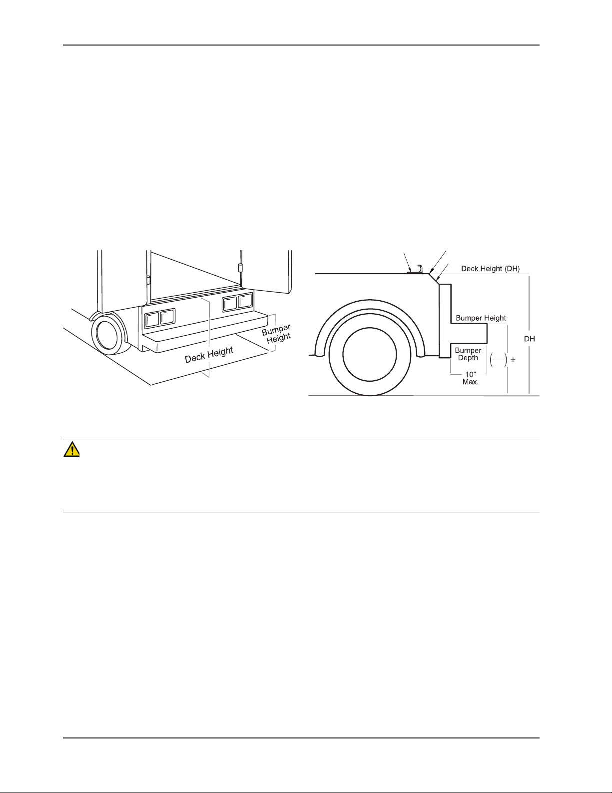
VEHICLE CONFIGURATION
According to federal regulations (reference KKK-A-1822), the bumper height of the vehicle shall be installed equidistant
± 5 cm (2 inches) from the vehicle floor to the ground level, which is defined as the vehicle deck height. The bumper
step shall have a minimum depth of 13 cm (5 inches) and a maximum depth of 25 cm (10 inches). If the bumper depth
is greater than 18 cm (7 inches), then the bumper must be able to fold. Installation of the safety hook into any vehicle
compliant with this federal specification provides adequate clearance for the cot base to lower to its fully extended
position. The cot is compatible with all vehicle deck heights (see specifications for maximum load height) as long as
the vehicle meets the federal specifications that are outlined in KKK-A-1822.
Sill Edge
Sill
DH
2
2
Figure 7: Vehicle Deck Height
Safety Hook
Figure 8: Vehicle Deck Height
CAUTION
• Set the cot load height to the proper stop height prior to operation.
• Installation of the safety hook should be done by a certified mechanic familiar with ambulance vehicle construction.
Consult the vehicle manufacturer before installing the safety hook and be sure that the installation of the safety hook
does not damage or interfere with the brake lines, oxygen lines, fuel lines, fuel tank or electrical wiring of the vehicle.
REQUIRED HARDWARE FOR INSTALLATION OF THE SAFETY HOOK (NOT SUPPLIED)
(2) Grade 5, Minimum 1/4”-20 Socket Head Cap Screws* for the short or long safety hook
(2) Grade 5, Minimum 1/4”-20 Flat Socket Head Cap Screws* for the J hook
(2) Flat Washers
(2) Lock Washers
(2) 1/4”-20 Nuts
* The length of the socket head cap screws depends on the thickness of the vehicle floor. Use screws that are long
enough to go completely through the patient compartment floor, washer and nut by at least two full threads.
Return To Table of Contents
20 6086-009-001 REV B www.stryker.com
Page 21
Vehicle Safety Hook Installation
Note: These installation instructions are intended for cots that you will NOT use with Power-LOAD. For Model 6086
cots with the Power-LOAD option, see the Power-LOAD Operations/Maintenance Manual for installation instructions.
WARNING
• Have the vehicle safety hook installed by a certified mechanic. Improper safety hook installation can cause injury
to the patient or operator and/or damage to the cot.
• Failure to install the safety hook can cause injury to the patient or operator.
• The face of the safety hook that engages the safety bar should be located at least 3-3/4” from the leading edge
of the door sill. After installation, verify that the cot legs lock into the load position without contacting the vehicle
bumper.
• To avoid injury, verify that the safety bar has engaged the safety hook before removing the cot from the patient
compartment.
Note: Stryker recommends that, prior to installation, the certified mechanic plan the placement of the safety hook in
the rear of the vehicle.
Before installing the safety hook into your vehicle, check the front to back and side to side positioning when unloading
and loading the cot to ensure that the safety hook will be installed properly. The cot safety bar must engage the safety
hook every time, regardless of cot position.
FRONT TO BACK POSITIONING OF THE SAFETY HOOK
1. Select the appropriate safety hook for your vehicle configuration.
2. Position the safety hook at least 3-3/4” from the leading edge of the door sill.
3. Ensure that the safety hook can be securely mounted into the back of the vehicle while providing adequate bumper
clearance to allow the cot to be loaded and unloaded from the vehicle.
4. See “Side to Side Positioning of the Safety Hook” to confirm the side to side placement.
Long Safety Hook
6060-036-018
Short Safety Hook
6060-036-017
J-Style Safety Hook
6092-036-018
Figure 9: Safety Hook Placement
Return To Table of Contents
www.stryker.com 6086-009 -001 REV B 21
Page 22
Vehicle Safety Hook Installation
Note: These installation instructions are intended for cots that you will NOT use with Power-LOAD. For Model 6086
cots with the Power-LOAD option, see the Power-LOAD Operations/Maintenance Manual for installation instructions.
SIDE TO SIDE POSITIONING OF THE SAFETY HOOK
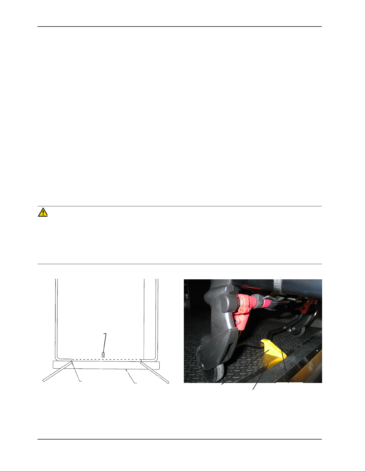
1. Remove the cot from the fastener and unload it from the vehicle.
2. While the cot is being removed, note the position of the load wheels and the safety bar.
3. Mark the center of the cot safety bar on the vehicle floor.
4. Verify that the position marked in Step 3 is where the safety bar engages the safety hook every time when
unloading the cot in a variety of positions (all the way to the left and all the way to the right), regardless of cot
position.
• If the cot safety bar does not engage the safety hook in any of these positions (left, center, or right), modify
the vehicle, not the cot or safety hook.
• If the cot safety bar engages the safety hook every time, install the safety hook.
INSTALLING THE SAFETY HOOK
1. Determine the correct safety hook front to back and side to side positioning, so the cot safety bar engages the
safety hook every time.
2. Drill the holes for the screws.
3. Fasten the safety hook to the patient compartment floor and verify that the safety hook always engages the cot
safety bar regardless of how the cot is unloaded from the vehicle.
WARNING
• Verify that the safety hook always engages the cot safety bar regardless of how the cot is unloaded from the
vehicle or injury to the patient or operator and/or damage to the cot may occur.
• The cot must have at least 5/8” of clearance between the vehicle bumper and the cot to disengage the safety bar
when unloading the cot from the vehicle. Verify that the cot legs lock into the load position before disengaging the
safety bar from the safety hook. Failure to properly lock the cot height into position can cause injury to the patient
or operator and/or damage to the cot.
Top View of Vehicle
Bumper
Squad Bench
Safety Hook
Floor Edge
Safety Bar
Safety Hook
Door Frame
Figure 10: Safety Hook Placement
(For Reference Only)
Return To Table of Contents
22 6086-009-001 REV B www.stryker.com
Figure 11: Safety Bar Engaging Safety Hook
Page 23
Adjusting Cot Load Height
Before placing the cot into service, confirm that the cot load height is set correctly for your vehicle. The cot load height
can be adjusted to match the height of the vehicle deck. If the cot does not line up correctly, adjustments may need
to be made to the cot load height.
WARNING
Before placing the cot into service, confirm that the cot load height is set correctly for your vehicle.
To check the load height of the Performance-PRO™ XT cot:
1. Roll the cot up to the loading area of your vehicle.
2. Compare the difference between the deck height of the
vehicle and the load height of the cot.
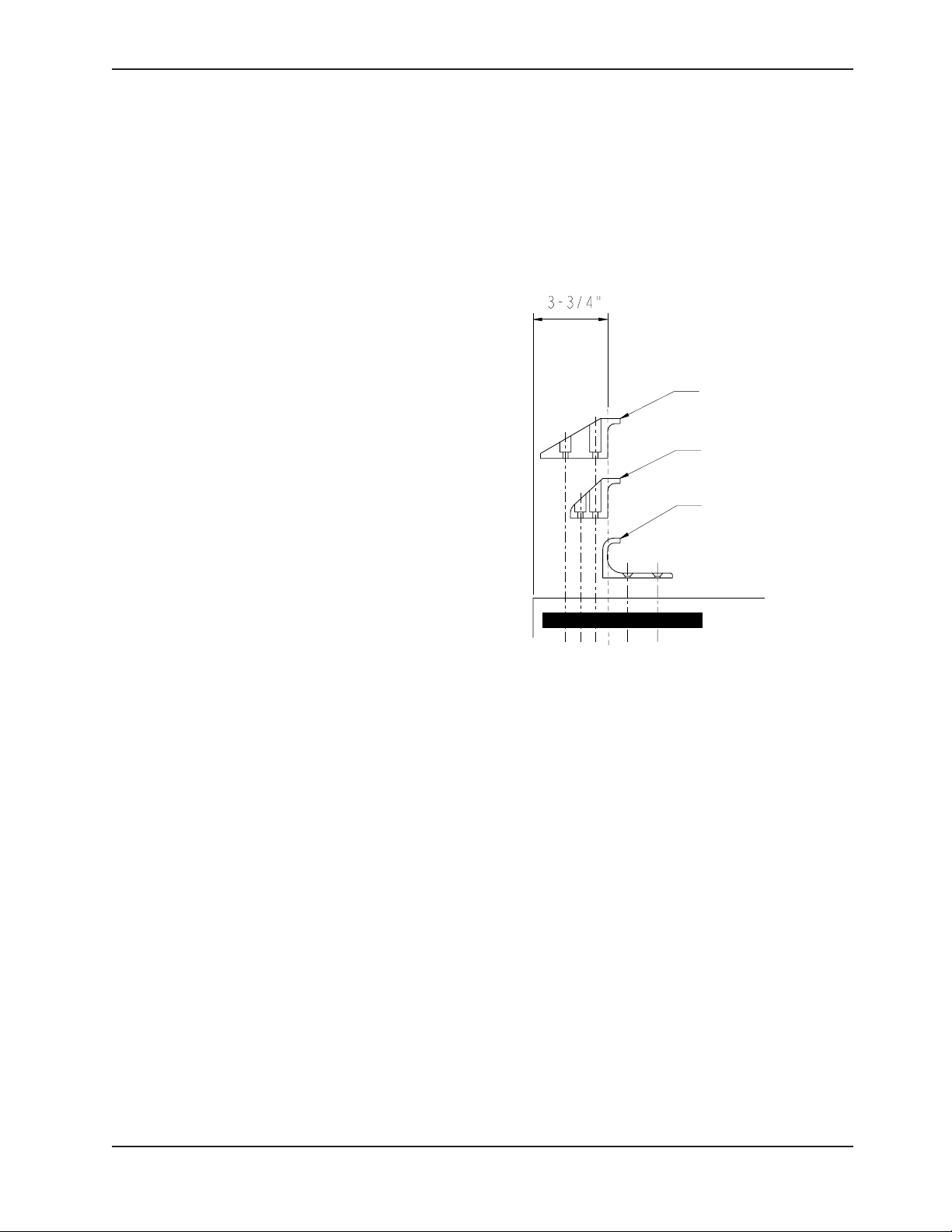
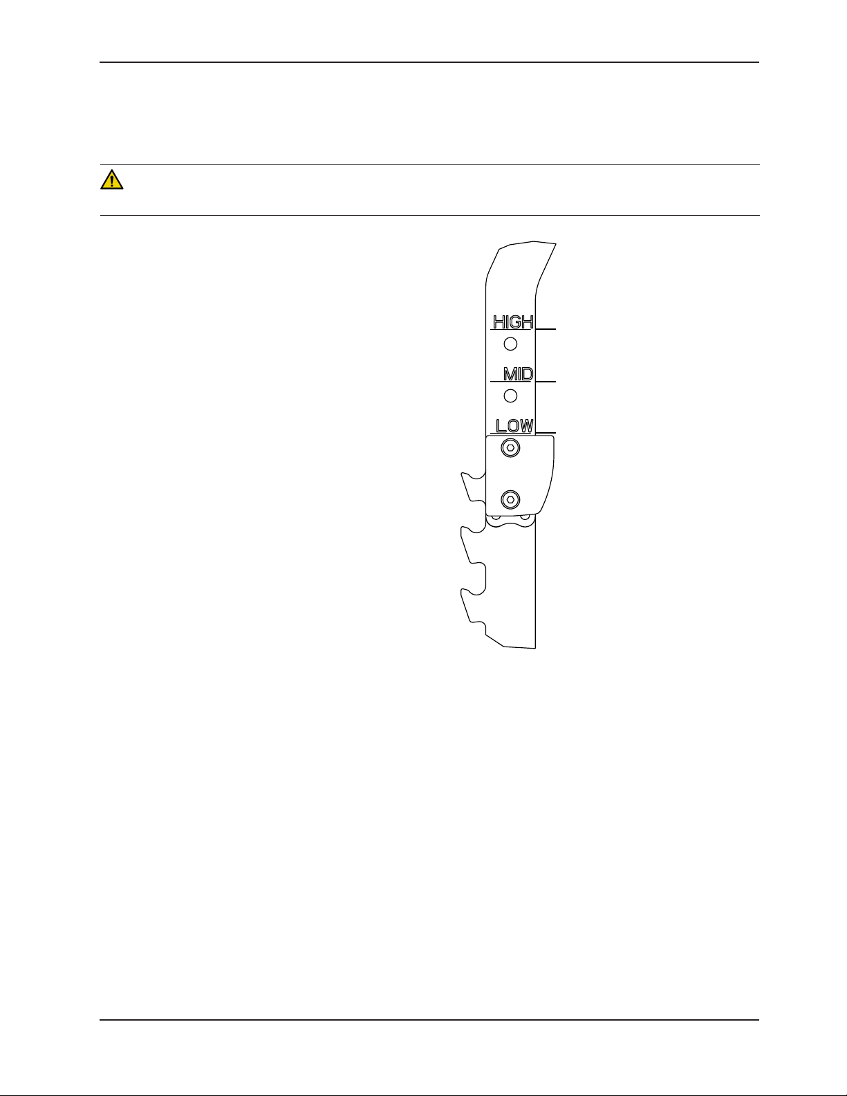
3. Select HIGH, MID or LOW depending on the cot load
height requirements (see Figure 12). For example:
• The HIGH marking on the rack is recommended for
vehicle deck heights above 32 inches.
• The MID marking on the rack is recommended for
vehicle deck heights between 30 and 32 inches.
• The LOW marking on the rack is recommended for
vehicle deck heights below 30 inches.
4. Verify that the safety hook always engages the cot safety
bar, regardless of how the cot is unloaded from the
vehicle. If the safety bar misses the safety hook, select
the next lower height setting.
For deck heights above 32”
For deck heights between 30-32”
For deck heights below 30”
Figure 12: Cot Load Height
Return To Table of Contents
www.stryker.com 6086-009 -001 REV B 23
Page 24
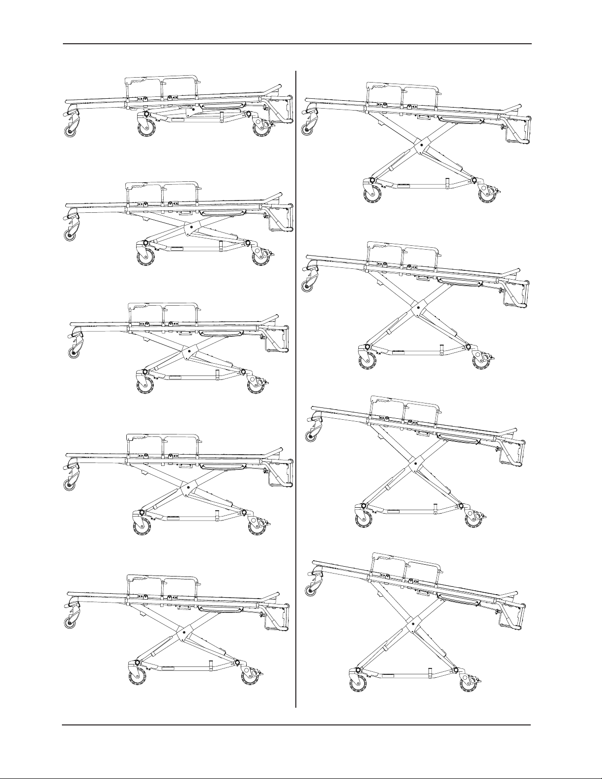
Cot Positions
Position 1 - Use for patient transfer
Position 2 - Use for patient transfer/cot rolling
Position 6 - Use for patient transfer/cot rolling
Position 3 - Use for patient transfer/cot rolling
Position 4 - Use for patient transfer/cot rolling
Position 7 - Use for patient transfer/cot rolling (LOW)
Position 8 - Use for patient transfer/cot rolling (MID)
Position 5 - Use for patient transfer/cot rolling
Return To Table of Contents
24 6086-009 -001 REV B www.stryker.com
Position 9 - Use for patient transfer/cot rolling (HIGH)
Page 25

Operation Guide
OPERATING GUIDELINES
• Use the cot only as described in this manual.
• Read all labels and instructions on the cot before using the cot.
• Loading an occupied cot into a vehicle requires a minimum of two (2) trained operators. One or two operators
can lift from the foot end of the cot. Stryker recommends that both operators are at the foot end to reduce the
load on each operator. If additional assistance is needed, see “Using Additional Assistance” on page 34.
• Do not adjust, roll or load the cot into a vehicle without advising the patient. Stay with the patient and control the
cot at all times.
• The cot can be transported in any position. Stryker recommends that the operators transport the patient in the
lowest comfortable position to maneuver the cot.
• Only use the wheel locks during patient transfer or without a patient on the cot.
• Do not leave wheel locks engaged while transporting the cot. Failure to do so may cause wheel damage.
• Always use the restraint straps.
• Use properly trained helpers, when necessary, to control the cot.
WARNING
• Improper usage of the cot can cause injury to the patient or operator. Operate the cot only as described in this
manual.
• Practice changing height positions and loading the cot until operation of the product is fully understood. Improper
use can cause injury.
• Do not allow untrained assistants to assist in the operation of the cot. Untrained technicians/assistants can cause
injury to the patient or themselves.
• Ensure proper hand placement on hand grips. Hands should be clear of red safety bar pivots while loading and
unloading the cot or whenever changing height position of the cot with two or more operators.
• Do not ride on the base of the cot. Damage to the product could occur, resulting in injury to the patient or operator.
• Transporting the cot sideways can cause the cot to tip, resulting in possible damage to the product and/or injury to the
patient or operator. Transporting the cot in a lowered position, head or foot end first, minimizes the potential of a cot tip.
• Grasping the cot improperly can cause injury. Keep hands, fingers and feet away from moving parts. To avoid injury,
use extreme caution when placing your hands and feet near the base tubes while raising and lowering the cot.
CAUTION
Before operating the cot, clear any obstacles that may interfere and cause injury to the operator or patient.
PROPER LIFTING TECHNIQUES
When lifting the cot and patient, there are five basic guidelines to help you avoid injury:
• Keep your hands close to your body.
• Keep your back straight.
• Coordinate your movements with your partner and lift with your legs.
• Avoid twisting.
• Always operate the cot as described in this manual.
Return To Table of Contents
www.stryker.com 6086-009 -001 REV B 25
Page 26

Operation Guide
TRANSFERRING THE PATIENT TO THE COT
To transfer the patient to the cot:
1. Roll the cot to the patient.
2. Place the cot beside the patient and raise or lower the cot to the level of the patient.
3. Lower the siderails and open the restraint straps.
4. Transfer the patient to the cot using accepted EMS procedures.
5. Use all the restraint straps to secure the patient to the cot (see page 40).
6. Adjust the backrest and foot rest as necessary.
Note: When transferring larger patients, use of the Transfer Flat (6005-001-001) is recommended.
WARNING
• Always use all restraint straps to secure the patient on the cot. An unrestrained patient may fall from the cot and
be injured.
• Never leave a patient unattended on the cot or injury could result. Hold the cot securely while a patient is on the
product.
• Never apply the optional wheel locks while a patient is on the cot. Tipping could occur if the cot is moved while
the wheel lock is applied, resulting in injury to the patient or operator and/or damage to the cot.
• Siderails are not intended to serve as a patient restraint device. See page 40 for proper restraint strap usage.
Failure to use the restraint straps properly could result in patient injury.
ROLLING THE COT
When rolling the cot:
• Make sure that all of the restraint straps are securely buckled around the patient (see page 40).
• Position an operator at the foot end and one at the head end of the cot at all times when rolling the cot with a
patient on it.
• Approach door sills and/or other low obstacles squarely and lift each set of wheels over the obstacle separately.
WARNING
• High obstacles such as curbing, steps or rough terrain can cause the cot to tip, possibly causing injury to the
patient or operator.
• If the cot is equipped with the optional kickstand, make sure that the kickstand remains in the retracted position
and does not engage during transport.
• Transporting the cot in lower positions reduces the potential of a cot tip. If possible, obtain additional assistance or
take an alternate route.
Return To Table of Contents
26 6086-009-001 REV B www.stryker.com
Page 27
Operation Guide
ADJUSTING THE HEIGHT OF THE COT WITH TWO OPERATORS
WARNING
• Grasping the cot improperly can cause injury. Keep hands, fingers and feet away from moving parts. To avoid injury, use extreme caution when placing your hands and feet near the base tubes while raising and lowering the cot.
• Ensure proper hand placement on hand grips. Hands should be clear of red safety bar pivots while loading and
unloading the cot or whenever changing height position of the cot with two or more operators.
• When operating the side release handle, keep hands away from the foot end release handle to avoid injury.
You can raise or lower an unoccupied cot with one operator. If a patient is on the cot, a minimum of two (2) trained
operators (one located at each end of the cot) are required to raise or lower the of the cot.
To raise or lower the cot from the ends:
1. The operator at the foot end of the cot squeezes the release handle (A or B) while a secure grip is maintained on
the lifting bars (see Figure 13).
2. Both operators must lift the cot until the weight is off the latching mechanism (approximately 1/4”).
3. The operator at the foot end squeezes and holds the release handle and both operators then raise or lower the cot
together. The handle is released when the desired position is reached. Both operators should maintain a secure
grip on the litter frame until the latching mechanism is securely locked into position.
To raise or lower the cot from the sides:
1. Check the cot to determine if the
side release handle is on the patient
left or right side.
2. The operator on the patient’s right
or left (depending on the location
of the release handle) reaches the
release handle at the midpoint of
the litter (C). Both operators must
lift the cot until the weight is off the
latching mechanism (approximately
1/4”) (see Figure 13).
3. The operator at the patient’s right or
left (depending on the location of the
release handle) squeezes and holds
the release handle. Both operators
then raise or lower the cot together.
The handle is released when the
desired position is reached. Both
operators should maintain a secure
grip on the litter frame until the
latching mechanism is securely
locked into position.
C
A
B
D
Figure 13: Adjusting the Cot Height
Return To Table of Contents
www.stryker.com 6086-009 -001 REV B 27
Page 28
Cot Operation
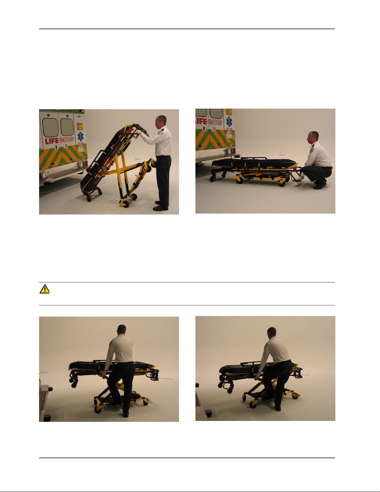
ADJUSTING THE HEIGHT OF AN EMPTY COT WITH ONE OPERATOR
To raise or lower the cot from the foot end:
1. Standing at the foot end of the cot, grasp the lower foot end lift tube.
2. Tip the cot up onto the load wheels (see Figure 14).
3. Squeeze and hold the release handle and raise or lower the foot end to the desired position. The handle is
released when the desired position is reached.
4. Lower the cot back onto the four base wheels (see Figure 15).
Figure 14: Cot Tipped on Load Wheels
To raise or lower the cot from the side:
1. Place one foot on the outer base tube.
2. Grasp the side release handle with one hand. Place your other hand on the outer support rail to help stabilize the
cot (see Figure 16).
3. Squeeze the side release handle and raise or lower the cot to the desired position. The handle is released when
the desired position is reached (see Figure 17).
Figure 15: Cot Lowered to Ground
WARNING
If lowering the cot to the lowest position (position 1), remove your foot from the base tube or injury could result.
Figure 16: Holding Outer Support Rail
Return To Table of Contents
28 6086-009-001 REV B www.stryker.com
Figure 17: Lowering Cot from Side
Page 29

Operation Guide
LOADING OR UNLOADING THE COT
The cot loading and unloading instructions on page 30 through page 33 are intended for cots that you will NOT use
with Power-LOAD. For Model 6086 cots with the Power-LOAD option, see the Power-LOAD Operations/Maintenance
Manual for loading and unloading instructions.
LOADING OR UNLOADING THE COT WITH THE POWER-LOAD OPTION
The Model 6086 Performance-PRO™ XT cot is fully compatible with the Model 6390 Power-LOAD system if it is
ordered with the Power-LOAD option or compatibility kit.
For more information about using your Power-LOAD compatible cot, see the Power-LOAD Operations/Maintenance
Manual.
WARNING
• Power-LOAD is designed to be compatible with the 6085/6086 Performance-PRO XT, 6500/6506 Power-PRO XT,
and 6510/6516 Power-PRO IT cots with the Power-LOAD option only. In certain situations, you can use PowerLOAD as a standard antler for most X-frame cots, but a rail clamp assembly is required for all cots without the
Power-LOAD option.
• It is the responsibility of the cot operator to ensure that the cot being used in the Stryker Model 6390 Power-LOAD
system is a Power-LOAD compatible cot. Injury may result if a non-compatible cot is used in the Stryker Model
6390 Power-LOAD system.
Return To Table of Contents
www.stryker.com 6086-009 -001 REV B 29
Page 30
Operation Guide
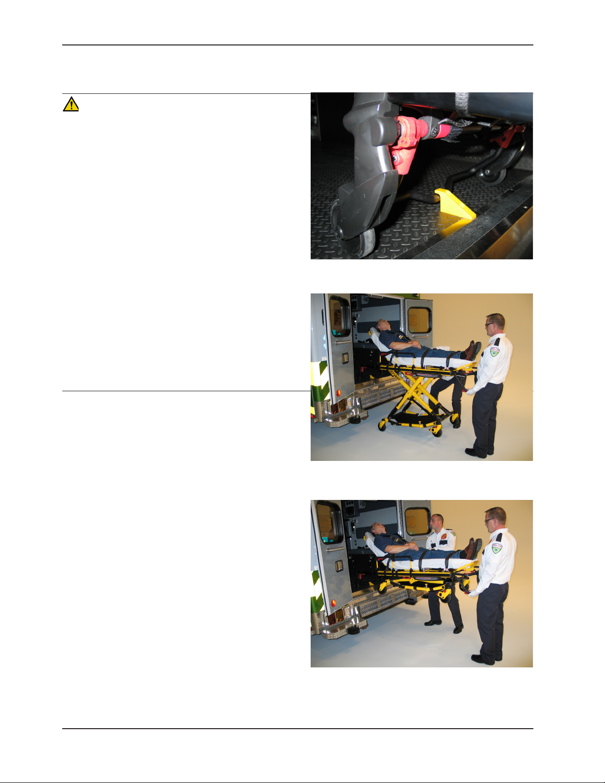
LOADING THE COT INTO A VEHICLE WITH TWO OPERATORS
WARNING
• Two operators must be present when the cot is
occupied.
• Operators must be able to lift the total weight of the
patient, cot and any items on the cot.
• The higher an operator must lift the cot, the more
difficult it becomes to hold the weight. An operator
may need help loading the cot if he/she is too short
or if the patient is too heavy to lift safely. The operator
must be able to lift the cot high enough for the cot
legs to unfold completely and lock when the cot is
unloaded. A shorter operator needs to raise their arms
higher to enable the undercarriage to unfold.
• Ensure proper hand placement on hand grips. Hands
should be clear of red safety bar pivots while loading
and unloading the cot or whenever changing height
position of the cot with two or more operators.
• There must be a safety hook properly installed in the
vehicle so that the bumper does not interfere with the
front legs of the base frame. (See page 20 for safety
hook installation instructions.)
• Failure to install the safety hook can cause injury to the
patient or operator. Install and use the safety hook as
described on page 20.
Figure 18: Safety Bar Engaging the Safety Hook
To load the cot into a vehicle with two operators:
1. Place the cot in a loading position (any position where
the loading wheels meet the vehicle floor height). Roll
the cot to the open door of the patient compartment.
Lift the vehicle bumper to the raised position (if
equipped).
2. Push the cot forward until the loading wheels are
on the patient compartment floor and the safety bar
passes the safety hook as shown in Figure 18.
3. For maximum clearance to lift the base, pull the cot
back until the safety bar engages the safety hook.
Operator 2 should verify that the bar engages the
safety hook.
4. Operator 1 − Grasp the cot frame at the foot end. Lift
the foot end of the cot until the weight is off of the
latching mechanism. Squeeze and hold the release
handle (A or B, as shown in Figure 13 on page 27).
5. Operator 2 − Stabilize the cot by placing your hand on
the outer rail (C). Grasp the base frame where indicated
(D). After the foot end operator lifts the cot and
squeezes the release handle, raise the undercarriage
until it stops in the uppermost position and hold it there
(see Figure 19). The foot end operator should release
the handle to lock the base in the retracted position.
6. Both Operators − Push the cot into the patient
compartment (see Figure 20), engaging the cot fastener (not included).
Figure 19: 2 Operators with One Lifting the Base
Figure 20: 2 Operators with Base Full Up
Return To Table of Contents
30 6086-009-001 REV B www.stryker.com
Page 31

Operation Guide
LOADING AN EMPTY COT INTO A VEHICLE WITH ONE OPERATOR
WARNING
• The one person loading and unloading procedures
are for use only with an empty cot. Do not use the
procedures when loading or unloading a patient. Injury
to the patient or operator could result.
• Ensure proper hand placement on hand grips. Hands
should be clear of red safety bar pivots while loading
and unloading the cot or whenever changing height
position of the cot with two or more operators.
To load an empty cot into a vehicle with one operator:
1. Place the cot in a loading position (any position in
which the load wheels meet the vehicle floor height).
2. Lift the vehicle bumper to the raised position (if
equipped).
3. Roll the cot to the open door of the patient
compartment.
4. Push the cot forward until the loading wheels are on
the compartment floor and the safety bar passes the
safety hook.
5. Pull the cot back until the safety bar engages the
safety hook.
6. Grasp the cot frame at the foot end and squeeze and
hold the release handle (see Figure 21).
7. Lower the foot end of the cot to the ground, making
sure that the cot locks in position 1 (see Figure 22).
8. Lift the foot end of the cot until it is level with the
compartment floor (see Figure 23).
9. Grasp the base of the cot with one hand and pull up
the base of the cot towards the litter, reducing the
space between the base and the litter.
10. Push the cot into the patient compartment by guiding it
into the cot fastener.
Figure 21: Squeeze the Release Handle
Figure 22: Lower the Foot End of the Cot
WARNING
Do not pull or lift on the safety bar when unloading the
cot. Damage to the safety bar could result and injury to the
patient or operator could occur.
Figure 23: Pull Up the Base of the Cot
Return To Table of Contents
www.stryker.com 6086-009 -001 REV B 31
Page 32

Operation Guide
UNLOADING THE COT FROM A VEHICLE WITH TWO OPERATORS
WARNING
• Failure to install the safety hook can cause injury to the patient or operator. Install and use the safety hook as
described on page 20.
• To avoid injury, verify that the safety bar has engaged the safety hook before removing the cot from the patient
compartment.
• Do not pull or lift on the safety bar when unloading the cot. Damage to the safety bar could result and injury to
the patient or operator could occur.
• Ensure proper hand placement on hand grips. Hands should be clear of red safety bar pivots while loading and
unloading the cot or whenever changing height position of the cot with two or more operators.
To unload the cot from a vehicle with two operators:
1. Lift the vehicle bumper to the raised position (if
equipped).
2. Disengage the cot from the cot fastener. (For more
information about the cot fastener, see page 17).
3. Operator 1 − Grasp the cot frame. Pull the cot out of
the patient compartment until the safety bar engages
the safety hook (see Figure 24).
4. Operator 2 − Grasp the base frame where indicated, lift
slightly, and lower the base frame to its fully extended
position while operator 1 squeezes and holds the
release handle (see Figure 25).
5. Operator 1 − Let go of the release handle and make
sure that the undercarriage locks into place. Set the
cot onto the ground.
6. Operator 2 − Disengage the safety bar from the safety
hook by pushing the safety bar release lever forward.
7. Remove the cot loading wheels from the vehicle. Place
the cot in any position, except full down for rolling.
Figure 24: 2 Operators with Base Full Up
CAUTION
Do not allow the cot undercarriage to drop unassisted
(commonly known as a “hot drop”) when removing the cot
from the vehicle. Repeated hot dropping causes premature
wear or damage to the cot.
WARNING
Be sure that the undercarriage has engaged and is locked
before removing the loading wheels from the patient
compartment floor of the vehicle. An unlocked undercarriage
will not support the cot and injury to the patient or operator
could result.
Return To Table of Contents
32 6086-009-001 REV B www.stryker.com
Figure 25: 2 Operators with One Lowering the Base
Page 33

Operation Guide
UNLOADING AN EMPTY COT FROM A VEHICLE WITH ONE OPERATOR
WARNING
• The one person loading and unloading procedures
are for use only with an empty cot. Do not use the
procedures when loading or unloading a patient. Injury
to the patient or operator could result.
• Do not pull or lift on the safety bar when unloading the
cot. Damage to the safety bar could result and injury
to the patient or operator could occur.
• Ensure proper hand placement on hand grips. Hands
should be clear of red safety bar pivots while loading
and unloading the cot or whenever changing height
position of the cot with two or more operators.
To unload an empty cot from a vehicle with one
operator:
1. Lift the vehicle bumper to the raised position (if
equipped).
2. Disengage the cot from the cot fastener. (For more
information about the cot fastener, see page 17).
Grasp the cot frame at the foot end; pull the cot from
the vehicle until the safety bar engages the safety hook
(see Figure 26).
3. Lower the foot end of the cot to the ground (see Figure
27).
4. Squeeze and hold the release handle (see Figure 28)
and raise the foot end of the cot back to a level position
with the compartment floor.
5. Disengage the safety bar from the safety hook by
pushing the safety bar release lever forward and roll
the cot out of the vehicle.
Figure 26: Pull the Base of the Cot
Figure 27: Lower the Foot End of the Cot
Figure 28: Squeeze the Release Handle
Return To Table of Contents
www.stryker.com 6086-009 -001 REV B 33
Page 34

Operation Guide
USING ADDITIONAL ASSISTANCE
IF EQUIPPED WITH THE RIGHT HAND RELEASE OPTION
Changing Levels Rolling Loading/Unloading
Helper
Helper
Helper Helper
Helper
Two
Operators
Two
Helpers
Two
Operators
Four
Helpers
Helper
Operator
Helper
Operator
Helper
Helper
Operator
Helper
Operator
Helper
Operator
Helper
Operator
IF EQUIPPED WITH THE LEFT HAND RELEASE OPTION
Operator
Operator
Helper
Operator
Helper
Helper
Operator
Helper
Operator
Helper
Helper
Operator
Changing Levels Rolling Loading/Unloading
Operator
Two
Operators
Two
Helpers
Helper
Operator
Two
Operators
Four
Helpers
Helper
Return To Table of Contents
34 6086-009-001 REV B www.stryker.com
Helper
Helper
Operator
Helper
Operator
Helper
Operator
Operator
Helper
Helper
Helper
Helper Helper
Helper
Operator
Operator
Operator
Helper
Operator
Helper
Helper
Helper
Operator
Helper
Helper
Operator
Page 35

Operation Guide
OPERATING THE SIDERAILS
To raise the siderails, as shown in Figure 29, lift up on the siderail until the latch clicks and the siderail locks into place.
To l o wer the siderails, squeeze handle (B) to release the siderail latch. Guide the siderail down toward the foot end
until flat. Ensure that the siderails are lowered when a patient is being transferred to or from the cot.
WARNING
Siderails are not intended to serve as a patient restraint device. See page 40 proper restraint strap usage. Failure to
use the siderails properly could result in patient injury.
A
B
Head End
Figure 29: Backrest Elevated and Siderails Raised
OPERATING THE BACKREST
To raise the backrest, as shown in Figure 29, squeeze handle (A) for pneumatic assist in lifting the backrest to the
desired height.
To lower the backrest, squeeze handle (A) and push down on the backrest frame until the backrest has reached the
desired height.
Return To Table of Contents
www.stryker.com 6086-009 -001 REV B 35
Page 36

Operation Guide
OPERATING THE RETRACTABLE HEAD SECTION
The head section telescopes from a first position suitable for
loading the cot into an emergency vehicle to a second position
retracted within the litter frame. When retracted, the cot can
roll in any direction on the caster wheels even in the lowest
position, allowing improved mobility and maneuverability.
To extend the head section:
1. Grasp the outer rail with one hand for support and pull
the handle (A), rotating the handle towards the head end
of the cot to release the head section from the locked
position
2. While holding the handle (A) in the released position, pull
the head section away from the litter frame, lengthening
the head section until it engages in the fully extended
position.
3. Release handle (A) to lock the head section in the extended
position.
To retract the head section:
1. Grasp the outer rail with one hand for support and release
the handle (A), rotate the handle towards the head end
of the cot to release the head section from the locked
position.
2. While holding the handle (A) in the released position, push
the head section toward the litter frame, retracting the
head section until it engages in the retracted position.
3. Release handle (A) to lock the head section in the retracted
position.
Figure 30: Head Section Extended
WARNING
• To avoid injury, always verify that the head section is
locked into place prior to operating the cot.
• Do not attempt to load the cot into the patient compartment
with the head section retracted. Loading the cot with the
head section retracted may cause the product to tip or not
engage properly in the cot fastener, possibly causing injury
to the patient or operator and/or damage to the product.
Figure 31: Head Section Retracted
A
Figure 32: Head Section Release Handles
Return To Table of Contents
36 6086-009 -001 REV B www.stryker.com
Page 37

Operation Guide
ADJUSTING THE FOOTREST
The footrest is adjustable to allow for elevation of the patient’s legs (see Figure 33).
To raise the footrest, lift the foot rest frame (A) as high as possible until it locks into place. The support bracket
engages automatically when released.
To lower the footrest, lift the foot rest frame (A) and, while holding the frame, lift up on the release handle (B) until the
bracket disengages. Carefully lower the footrest until it rests flat.
A
B
Foot End
Figure 33: Footrest Elevated
Return To Table of Contents
www.stryker.com 6086-009 -001 REV B 37
Page 38

Operation Guide
ADJUSTING THE OPTIONAL KNEE GATCH
To raise the knee gatch (see Figure 34):
1. Lift either of the red lifting loops (A) until the knee gatch is in its fully raised position.
2. Slowly lower the knee gatch to allow the support bracket to engage in the locking mechanism.
3. Check to be sure the lock is fully engaged before releasing the lifting loop.
To lower the knee gatch:
1. Lift either of the red lifting loops to relieve pressure on the locking mechanism and while holding the loop, push on
the red release handle (B) until the bracket disengages.
2. Carefully lower the knee gatch to the flat position.
A
B
C
Figure 34: Raised Knee Gatch
To raise the knee gatch in trend (see Figure 35):
1. Lift the foot rest frame (C) as high as possible until it locks into place.
2. The support bracket engages automatically when released.
To lower the knee gatch in trend:
1. Lift the foot rest frame (C) and, while holding the frame, lift up on the release handle (B) until the bracket
disengages.
2. Carefully lower the footrest until it rests flat.
Return To Table of Contents
38 6086-009-001 REV B www.stryker.com
Figure 35: Raised Knee Gatch in Trend
Page 39

Operation Guide
OPERATING THE OPTIONAL WHEEL LOCKS
To activate the optional wheel locks, press fully down on the pedal (A) as shown in Figure 36 until it stops and is
resting firmly against the surface of the wheel.
To release the optional wheel locks, depress the upper face of the pedal with your foot or lift up with your toe under
the pedal. The upper portion of the pedal will rest against the caster frame when the wheel lock is released.
A
Figure 36: Wheel Lock
WARNING
• Never apply the optional wheel locks while a patient is on the cot. Tipping could occur if the cot is moved while a
wheel lock is applied, resulting in injury to the patient or operator and/or damage to the cot.
• Never leave a patient unattended on the cot or injury could result. Hold the cot securely while a patient is on the
cot.
• Never install or use wheel locks on a cot with excessively worn wheels. Installing or using wheel locks on wheels
with less than a 6” diameter could compromise the holding ability of the wheel lock, resulting in injury to the patient
or operator and/or damage to the cot or other equipment.
CAUTION
Wheel locks are only intended to help prevent the cot from rolling while unattended and to aid in patient transfer. A wheel
lock may not provide sufficient resistance on all surfaces or under loads.
Return To Table of Contents
www.stryker.com 6086-009 -001 REV B 39
Page 40

Operation Guide
USING RESTRAINT STRAPS
WARNING
Always use all restraint straps to secure the patient on the cot. An unrestrained patient may fall from the cot and be
injured.
Always secure the patient on the cot with all of the restraint straps.
To attach the restraint strap to the cot:
1. Wrap the restraint strap around the cot frame as shown in Figure 37.
2. Push the restraint strap buckle through the loop as shown in Figure 38.
3. Pull the buckle through the loop to secure the restraint strap to the cot as shown in Figure 39.
Figure 37: Wrap strap around cot Figure 38: Push buckle through loop Figure 39: Pull strap to tighten
4. Repeat steps 1-3 until all restraint straps are securely attached to the cot in the required attachment locations as
shown in Figure 40.
Buckle the restraints across the patient’s chest/shoulders, waist
and legs. Note the attachment locations in Figure 41.
Keep the restraint straps buckled (as shown in Figure 40) when
the cot is not being used with a patient to avoid damage to the
buckles and straps.
Figure 40: Restraint Strap Locations
Return To Table of Contents
40 6086-009- 001 REV B www.stryker.com
Page 41

Operation Guide
USING RESTRAINT STRAPS (CONTINUED)
When attaching the restraint straps to the cot, the attachment points should provide both strong anchorage and proper
restraint position while not interfering with equipment and accessories.
WARNING
Do not attach restraints to the base tubes, cross tubes, or fowler skin. Improper
restraint attachment could result in damage to the cot further resulting in injury to the
patient or operator.
(Back View)
Shoulder/Chest Restraint Straps
Knee Restraint Straps
Foot Restraint Straps
Figure 41: All Straps (Front View)
Return To Table of Contents
www.stryker.com 6086-009 -001 REV B 41
Page 42

Operation Guide
USING RESTRAINT STRAPS (CONTINUED)
CAUTION
Ensure that the restraints are not entangled in the base frame when raising and lowering the cot.
When the cot is put into service, open the restraints and place them at either side of the cot until the patient is
positioned on the cot mattress. Lengthen the restraints, buckle them around the patient and shorten them until the
required tightness is achieved.
• To open the restraint, press the red button (A) on the front of the buckle “receiver”. This releases the buckle latch
plate (B) which can then be pulled out of the receiver (Figure 42).
• To close the restraint, push the latch plate into the receiver until a “click” is heard. When fastening the chest
restraint ensure that the latch plate passes through both links (C) on the shoulder strap (Figure 42).
• To lengthen the restraint, grasp the buckle latch plate, turn it at an angle to the webbing, then pull it out (Figure
43). A hemmed tab at the end of the webbing prevents the latch plate from coming off of the strap.
• To shorten the restraint, grasp the hemmed tab and pull the webbing back through the latch plate until the
required tightness is achieved (Figure 44).
C
C
A
Figure 42: Buckling the Safety Restraints
Whenever a restraint is buckled on a patient, verify that the latch plate is fully engaged and any extra webbing is not
tangled in the cot or hanging loose.
B
Figure 43: Lengthening the Safety Restraint
Figure 44: Shortening the Safety Restraint
Inspect the restraints at least once a month (more frequently if used heavily). Inspection should include checking for a
bent or broken receiver or latch plate, torn or frayed webbing, etc. Any restraint showing wear or not operating properly
must be replaced immediately.
Return To Table of Contents
42 6086-009-001 REV B www.stryker.com
Page 43

Operation Guide
USING THE RESTRAINT BELT EXTENSION
Use the restraint belt extension, as shown in Figure 45, for extra length when buckling the lap belt around large patients.
Figure 45: Attaching the Restraint Belt Extension
Return To Table of Contents
www.stryker.com 6086-009 -001 REV B 43
Page 44

Optional Accessories
The accessories listed below can be purchased and installed on the Performance-PRO™ XT cot.
Accessory Part Number
Base Storage Net 6500-160-000 page 45
Defibrillator Platform 6500-170-000 page 45
Equipment Hook 6500-147-000 page 46
Head Extension with Pillow 6100-044-000 page 46
I.V. Pole Assembly, Two-Stage, Right 6500-210-000 page 47
I.V. Pole Assembly, Three-Stage, Right 6500-215-000 page 48
I.V. Pole Assembly, Two-Stage, Left 6500-211-000 page 47
I.V. Pole Assembly, Three-Stage, Left 6500-216-000 page 48
I.V. Pole Assembly, Two-Stage, Dual 6500-212-000 page 47
I.V. Pole Assembly, Three-Stage, Dual 6500-217-000 page 48
Kickstand Assembly 6085-002-000 page 49
Oxygen Bottle Holder, Foot End 6500-140-000
Operation Guide
Page Number
page 50Oxygen Bottle Holder, Head End 6500-141-000
Oxygen Bottle Holder, Removable 6080-140-000
Oxygen Bottle Holder, Retractable Head Section 6085-046-000 page 51
Pedi-Mate Restraint Package 6091-300-010 page 52
Pocketed Back Rest Pouch 6500-130-000 page 54
Storage Flat, Head End 6085-035-000 page 55
Transfer Flat 6005-001-001 page 55
Return To Table of Contents
44 6086-009-001 REV B www.stryker.com
Page 45

Optional Accessories
INSTALLING THE BASE STORAGE NET
To install the base storage net, wrap the Velcro® straps around the base tubes.
CAUTION
• The weight of the equipment in the base storage net (if equipped) must not exceed 20 lb (9 kg).
• Be careful when retracting the base to avoid damaging items stored in the base storage net.
Note: The kickstand (p/n 6085-002-000) is not compatible with the optional base storage net (p/n 6500-160-000).
USING THE DEFIBRILLATOR PLATFORM
See the Defibrillator Tray Operations/Maintenance manual for operation guide, safety precautions, cleaning, preventative
maintenance, assembly drawings, and warranty information.
Return To Table of Contents
www.stryker.com 6086-009 -001 REV B 45
Page 46

Optional Accessories
USING THE EQUIPMENT HOOK
Use the equipment hook (A) (see Figure 46) to hang additional accessories or equipment, such as defibrillators or
monitors.
CAUTION
To avoid damage to the equipment
hook, the weight of the accessories
or equipment must not exceed 35 lb
(15.9 kg).
A
Figure 46: Equipment Hook
USING THE HEAD EXTENSION WITH PILLOW
You can install the head extension assembly over the fowler to provide head end support.
Attach the pillow to the head extension by placing the support into the flap on the bottom of the pillow. Secure the
pillow to the Velcro® on the bottom of the support.
Note: The head extension with pillow (p/n 6100-044-000) is not compatible with the optional equipment hook (p/n
6500-147-000) or optional fowler oxygen bottle holder (p/n 6500-141-000).
Return To Table of Contents
46 6086-009-001 REV B www.stryker.com
Page 47

Optional Accessories
OPERATING THE OPTIONAL TWO-STAGE I.V. POLE
To use the two-stage I.V. pole (see Figure 48):
1. Lift and pivot the pole from the storage position and push down until it is locked into the receptacle (A).
2. To raise the height of the pole, turn the lock actuator (B) counterclockwise and pull up on the telescoping portion
(C) of the pole to raise it to the desired height.
3. Turn the lock actuator (B) clockwise to lock the telescoping portion in place.
4. Hang the I.V. bags on the I.V. hook (D).
5. Turn the lock actuator (B) counterclockwise and slide section (C) into the bottom tube.
6. Turn the lock actuator (B) clockwise to tighten.
7. Lift up and pivot the pole down into the storage position (see Figure 47).
CAUTION
To avoid damage to the I.V. pole, the weight of the I.V. bags or equipment must not exceed 40 lb (18 kg).
Note: The dual two-stage I.V. poles (p/n 6500-212-000) are not compatible with either the patient right (6500-210-000)
or patient left (6500-211-000) two-stage I.V. pole options.
C
C
Figure 47: Two-Stage I.V. Pole Storage Position
D
D
B
B
A
A
Figure 48: Two-Stage I.V. Pole
Return To Table of Contents
www.stryker.com 6086-009 -001 REV B 47
Page 48

Optional Accessories
OPERATING THE OPTIONAL THREE-STAGE I.V. POLE
To use the three-stage I.V. pole (see Figure 50):
1. Lift and pivot the pole from the storage position and push down until
it is locked into the receptacle (A).
2. To raise the height of the pole, turn the lock actuator (B)
counterclockwise and pull up on the bottom telescoping portion (C)
of the pole to raise it to the desired height.
3. Turn the lock actuator (B) clockwise to lock the bottom telescoping
portion in place.
4. For a higher I.V. pole, pull up on section (D) until the spring clip (E)
engages.
5. Hang I.V. bags on the I.V. hook (F).
6. To lower the I.V. pole, push in on the spring clip (E) and slide section
(D) down into section (C). Turn the lock actuator (B) counterclockwise
and slide section (C) into the bottom tube.
7. Turn the lock actuator (B) clockwise to tighten.
8. Lift up and pivot the pole down into the storage position (see Figure
49).
CAUTION
To avoid damage to the I.V. pole, the weight of the I.V. bags or equipment
must not exceed 40 lb (18 kg).
F
F
D
D
E
C
C
E
Note: The dual three-stage I.V. poles (p/n 6500-217-000) are not
compatible with either the patient right (6500-215-000) or patient left
(6500-216-000) two-stage I.V. pole options.
Figure 49: Three-Stage I.V. Pole Storage Position
B
A
A
B
Figure 50: Three-Stage I.V.
Pole
Return To Table of Contents
48 6086-009- 001 REV B www.stryker.com
Page 49

Optional Accessories
USING THE KICKSTAND FOR DIALYSIS SCALE
The kickstand is intended for weighing patients on a scale.
Note:
• The kickstand assembly is configured for an X-frame cot retention system only.
• The kickstand (p/n 6085-002-000) is not compatible with the optional base storage net (p/n 6500-160-000).
WARNING
• Stryker recommends a two person operation when using the kickstand.
• Make sure that the patient weight is centered on the cot before using the kickstand.
• Engage the kickstand with your foot only.
• Lower cot height prior to engaging kickstand for increased stability.
• Make sure that the kickstand remains in the retracted position and does not engage during transport.
• Do not use the kickstand as a brake.
• Do not engage kickstand on a sloped surface.
To use the kickstand:
1. Operator 1 engages the kickstand with their foot as shown in Figure 51.
2. Operator 2 lifts the foot end of the cot at a height sufficient to actuate the kickstand.
3. Both operators must make sure that the kickstand is in the forward locked position as shown in Figure 52.
Figure 51
To release the kickstand:
1. Operator 1 lifts the foot end of the cot until both wheels
are off of the floor.
2. Operator 2 rolls the cot slightly forward to make sure
that the kickstand retracts on its own as shown in
Figure 53.
www.stryker.com 6086-009 -001 REV B 49
Figure 52
Figure 53
Return To Table of Contents
Page 50

Optional Accessories
ATTACHING AN OXYGEN BOTTLE TO AN OXYGEN BOTTLE HOLDER
To attach an oxygen bottle:
1. Place an oxygen bottle in the holder.
2. Insert the lower strap through the buckle and affix the strap onto itself to secure the oxygen bottle to the holder.
Note: Inspect the straps and clips for wear between use and replace the strap if it is no longer holding the oxygen
bottle.
CAUTION
• To avoid damage to the oxygen bottle holder (if equipped), the weight of the equipment must not exceed 40 lb (18
kg).
• Do not use two head end oxygen bottle holders at the same time.
Note: The optional fowler oxygen bottle holder (p/n 6500-141-000) is not compatible with the optional retractable head
section oxygen bottle holder (p/n 6085-046-000).
Return To Table of Contents
50 6086-009 -001 REV B www.stryker.com
Page 51

Optional Accessories
USING THE RETRACTABLE HEAD SECTION OXYGEN BOTTLE HOLDER
To attach an oxygen bottle to the retractable head section oxygen bottle holder:
1. Center the oxygen bottle on the cradled surface of item (A) as shown in Figure 54.
2. Tighten both straps (B) around the oxygen bottle.
3. Secure the slack on the straps to the Velcro® on the straps.
B
A
Figure 54: Retractable Head Section Oxygen Bottle Holder
Note: Inspect the straps and clips for wear between use and replace the strap if it is no longer holding the oxygen
bottle.
WARNING
If the cot is equipped with the optional retractable head section oxygen bottle holder, use caution while the oxygen bottle
holder is installed to avoid pinching your fingers between the fowler bracket and the oxygen bottle.
CAUTION
• To avoid damage to the oxygen bottle holder (if equipped), the weight of the equipment must not exceed 40 lb (18
kg).
• Do not use two head end oxygen bottle holders at the same time.
Return To Table of Contents
www.stryker.com 6086-009 -001 REV B 51
Page 52

Optional Accessories
ATTACHING THE PEDI-MATE® INFANT RESTRAINT SYSTEM
See the Pedi-Mate® users manual for the manufacturer’s recommendations for the use, operation and care of the
Pedi-Mate® Infant Restraint System.
To secure the Pedi-Mate® to the cot:
1. Remove any restraints that are already attached to the cot.
2. Raise the cot backrest to the full upright position.
3. Position the Pedi-Mate® pad flat on the backrest with the black backrest straps out (see Figure 55).
Figure 55: Positioning the Pedi-Mate
4. Wrap the straps around the backrest and insert the ends of the straps through the brackets. Securely fasten the
buckle (see Figure 56).
Figure 56: Fastening the Pedi-Mate® Buckle
®
WARNING
To avoid accidental release of the Pedi-Mate®, and possible injury to the infant, ensure that the buckle is located away
from obstructions on the cot or accessories.
Return To Table of Contents
52 6086-009-001 REV B www.stryker.com
Page 53

Optional Accessories
ATTACHING THE PEDI-MATE® INFANT RESTRAINT SYSTEM (CONTINUED)
5. Pull firmly on the end of the adjustable backrest strap and tighten it securely.
6. Insert the mainframe straps between the cot frame and the mattress. To ensure that the release button is located
toward the foot end of the cot, insert the buckle behind the litter cross brace and bring it up in front of the cross
brace. Secure the buckle around the cross brace, leaving a little slack in the strap for final adjustment (see Figure
57).
Figure 57: Securing the Safety Restraints on a Cot
WARNING
To avoid accidental release of the Pedi-Mate®, and possible injury to the infant, ensure that the buckle is located away
from obstructions on the cot or accessories.
7. Verify that all of the straps are snug and fastened securely (see Figure 58).
Figure 58: Pedi-Mate® Strapped to a Cot
Note: These are general instructions for installation of the Pedi-Mate®. Safe and proper use of the Pedi-Mate® is solely
at the discretion of the user. Stryker recommends that all users be trained on the proper use of the Pedi-Mate® before
using it in an actual situation. Retain these instructions for future reference. Include them with the product in the event
of transfer to new users.
Pedi-Mate® is a registered trademark of Ferno-Washington, Inc.
Return To Table of Contents
www.stryker.com 6086-009 -001 REV B 53
Page 54

Optional Accessories
INSTALLING THE BACKREST STORAGE POUCH
Install the optional backrest storage pouch using the Velcro® straps as shown in Figure 59. Insert each strap through
a hole in the backrest skin and mount the pouch flat against the backrest.
CAUTION
• Do not store items under the cot mattress. Storing items under the mattress can interfere with the operation of
the cot.
• The weight of the equipment in the pocketed backrest storage pouch (if equipped) must not exceed 20 lb (9 kg).
Figure 59: Backrest Storage Pouch
Return To Table of Contents
54 6086-009-001 REV B www.stryker.com
Page 55

Optional Accessories
INSTALLING THE HEAD END STORAGE FLAT
WARNING
When the optional head end storage flat is being used, ensure that it does not interfere with the operation of the
retractable head section, safety bar and safety hook. Injury to the patient or operator could result.
A
B
Cross Bar
B
A
V-Tube
Figure 60: Head End Storage Flat
To install the optional head end storage flat (see Figure 60):
1. Install the Velcro® straps (A) near the pneumatic cylinder and around the cross bar of the retractable head section.
2. Buckle the restraint straps (B) around the outer rails of the retractable head section.
CAUTION
• Do not store items under the cot mattress. Storing items under the mattress can interfere with the operation of
the cot.
• The weight of the equipment in the head end storage flat (if equipped) must not exceed 40 lb (18 kg).
USING THE TRANSFER FLAT
When transferring larger patients, use of the Transfer Flat (6005-001-001) is recommended.
Return To Table of Contents
www.stryker.com 6086-009 -001 REV B 55
Page 56

Cleaning
The Performance-PRO™ XT cot is designed to be power washable. The unit may show some signs of oxidation or
discoloration from continuous washing, however, no degradation of the cot’s performance characteristics or functionality
will occur due to power washing as long as the proper procedures are followed.
Thoroughly clean the cot once a month. Clean Velcro® AFTER EACH USE. Saturate Velcro® with disinfectant and allow
disinfectant to evaporate. Appropriate disinfectant for nylon Velcro® should be determined by the service.
WASHING PROCEDURE
• Followthecleaningsolutionmanufacturer’sdilutionrecommendationsexactly.
• The preferred method Stryker Medical recommends for power washing the cot is with the standard hospital
surgical cart washer or hand held wand unit.
WASHING LIMITATIONS
WARNING
When cleaning, use any appropriate personal safety equipment (goggles, respirator, etc.) to avoid the risk of inhaling
contagion. Use of power washing equipment can aerate contamination collected during the use of the cot.
CAUTION
• DO NOT STEAM CLEAN OR ULTRASONICALLY CLEAN THE UNIT.
• Maximum water temperature should not exceed 180°F/82°C.
• Maximum water pressure should not exceed 1500 psi/130.5 bar. If a hand held wand is being used to wash the
unit, the pressure nozzle must be kept a minimum of 24 inches (61 cm) from the unit.
• Allow cot to air dry.
• Towel dry all casters and interface points.
• Failure to comply with these instructions may invalidate any/all warranties.
Return To Table of Contents
56 6086-009-001 REV B www.stryker.com
Page 57

Cleaning
In general, when used in those concentrations recommended by the manufacturer, either phenolic type or quaternary
(excluding Virex® TB) type disinfectants can be used. Iodophor type disinfectants are not recommended for use
because staining may result.
Suggested cleaners for the cot surfaces and restraint straps:
• Quaternary Cleaners (active ingredient - ammonium chloride)
• Phenolic Cleaners (active ingredient - o-phenylphenol)
• Chlorinated Bleach Solution (5.25% - less than 1 part bleach to 100 parts water)
Note: Do not immerse the restraint strap metal buckle components in water. Rinse with clean water. Allow to air dry.
Avoid over saturation and ensure that the product does not stay wet longer than the chemical manufacturer’s guidelines
for proper disinfecting.
WARNING
SOME CLEANING PRODUCTS ARE CORROSIVE IN NATURE AND MAY CAUSE DAMAGE TO THE PRODUCT IF USED
IMPROPERLY. If the products described above are used to clean Stryker EMS equipment, measures must be taken
to ensure the cots are wiped with clean water and thoroughly dried following cleaning. Failure to properly rinse and
dry the cots will leave a corrosive residue on the surface of the cots, possibly causing premature corrosion of critical
components.
Note: Failure to follow the above directions when using these types of cleaners may void this product’s warranty (see
page 155).
REMOVAL OF IODINE COMPOUNDS
Use a solution of 1/2 Tablespoon Sodium Thiosulfate in a pint of warm water to clean the stained area. Clean as soon
as possible after staining occurs. If stains are not immediately removed, allow solution to soak or stand on the surface.
Rinse surfaces which have been exposed to the solution in clear water before returning unit to service.
WARNING
Failure to properly clean or dispose of contaminated mattress or cot components will increase the risk of exposure to
bloodborne pathogens and may cause injury to the patient or the operator.
Return To Table of Contents
www.stryker.com 6086-009 -001 REV B 57
Page 58

Preventative Maintenance
Preventative maintenance should be performed at a minimum of annually. A preventative maintenance program should
be established for all Stryker Medical equipment. Preventative maintenance may need to be performed more frequently
based on the usage level of the product.
Operation Schedule Procedure
Cleaning and Disinfecting Each Use. See page 56.
For 1-25 calls per month,
inspect cot every 6 months
Inspection
Note: Use the Maintenance Record form on page 61 to keep up to date maintenance records.
For 26-200 calls per month,
inspect cot every 3 months
For 201+ calls per month,
inspect cot monthly.
See checklist below.
CHECKLIST
_____ All fasteners secure (reference assembly drawings).
_____ All welds intact, not cracked or broken.
_____ No bent or broken tubing or sheet metal.
_____ No wear on the bumper and bumper housing.
_____ No debris in wheels.
_____ All wheels secure, rolling and swiveling properly.
_____ Optional wheel lock holds wheel securely when on and clears wheel when off.
_____ Siderails move and latch properly.
_____ Backrest operating properly.
_____ Optional accessories intact and operating properly.
_____ Height positioning latch functioning properly.
_____ Cot secure in each height position.
_____ Undercarriage folds properly.
_____ Retractable head section operating properly.
_____ Safety bar operating properly.
_____ Footrest operating properly.
_____ No rips or cracks in mattress cover.
_____ Body restraints intact and working properly.
_____ Lubricate base tubes (optional).
Product Serial Number:
Completed by: ____________________________________________ Date: _____________________
Return To Table of Contents
58 6086-009 -001 REV B www.stryker.com
Page 59

Preventative Maintenance
Six months 12 M ont hs
months
X
X
One month Three
X
Verify the safety bar engages the vehicle safety hook properly
Verify all welds intact, not cracked or broken X
Verify no bent, broken or damaged components X
Verify all fasteners secure (reference assembly drawings) X
Verify warning labels present, legible (reference assembly drawings) X
Verify no damage or tears on cot grips X
Verify the siderails operate and latch properly X
Verify the backrest cylinder operates properly X
Adjust pneumatic cylinder for full range of motion, if required X
Verify the footrest operates properly X
Inspect the fowler bumper and screws X
Inspect the dead stop (6085-001-094) for wear. Replace if necessary X
REGULAR INSPECTION AND ADJUSTMENTS
Maintenance Intervals
Use this schedule as a general guide for maintenance. Factors such as weather, terrain, geographical location, and individual usage will alter the required
maintenance schedule. If you are unsure as to how to perform these checks, contact your Stryker service technician. If you are in doubt as to what intervals to
follow when maintaining your product, consult your Stryker service technician. Check each routine and replace damaged or worn parts if necessary.
www.stryker.com 6086-009 -001 REV B 59
Item Routine Every (whichever comes first)
Settings Verify the cot and fastener fit and function properly
Litter Inspect the cot frame/litter X
broken receiver or latch plate, torn or frayed webbing, etc.)
Verify all welds intact, not cracked or broken X
Mattress Verify no cracks or tears on cot mattress X
Restraints Inspect patient restraints for proper function and no excessive wear (bent or
Base Inspect the cot frame/base X
Return To Table of Contents
Verify no bent, broken, or damaged components X
Verify all fasteners secure (reference assembly drawings) X
Verify that the cot retaining post is secure. If not secure, replace the screw. See
“Cot Retaining Post Screw Replacement” on page 67.XVerify no excessive damage to X-frame guards X
Page 60

Preventative Maintenance
X
Six months 12 M ont hs
months
X
One month Three
lubrication
restraint package (optional) operates properly X
®
Verify the restraint extender (optional) operates properly X
Verify the oxygen bottle holder (optional) operates properly X
Verify the transfer flat (optional) operates properly X
Verify the equipment hook (optional) operates properly X
Verify the pocketed back rest pouch (optional) operates properly X
Verify the base storage net (optional) operates properly X
Verify rubber is in good condition X
Verify all wheels secure, rolling and swiveling properly X
Check and adjust optional wheel locks as necessary X
Item Routine Every (whichever comes first)
Return To Table of Contents
60 6086-009-001 REV B www.stryker.com
Wheels Verify wheels are free of debris X
Verify no bent, broken, or damaged components X
Verify the head section extends and locks properly X
Verify the grip bar has no excessive damage or tears X
Verify load wheels are secure and roll properly X
Verify the safety bar operates properly. Pull toward the head section to ensure
that it swings and rotates freely and pulls back to home position.
(optional) for wearXVerify the I.V. pole (optional) operates properly X
Verify the head extension & pillow (optional) operates properly X
Verify the Pedi-Mate
X-Frame Verify smooth operation of X-frame X
Head Section Verify all fasteners secure (reference assembly drawings) X
Accessories Inspect the straps and clips on the retractable head section oxygen bottle holder
Verify the kickstand (optional) retracts fully to the transport position X
®
lubrication Flow
®
Verify that the kickstand (optional) bolts are tightened properly X
Lubricate the kickstand spring and internal spring housing (optional) using Tri-
Flow
Page 61

Maintenance Record
Date Maintenance Operation Performed By Hours
Return To Table of Contents
www.stryker.com 6086-009 -001 REV B 61
Page 62

Training Record
Training Date Training Method
Trainee Name Basic
Training
Refresher
Update
Owner’s Manual, In-Service,
Formal Class, Etc.
Return To Table of Contents
62 6086-009-001 REV B www.stryker.com
Page 63

Quick Reference Replacement Parts List
The parts and accessories listed on these pages are all currently available for purchase. Some of the parts identified on the assembly drawing parts in this manual may not be individually available for purchase. Please call Stryker
Customer Service USA: 1-800-327-0770 (Option 2) for availability and pricing.
Part Name Part Number
Dead Stop 6085-001-094
Gas Spring 1010-031-077
Head Extension - Pillow Only 6100-045-000
Head Section 6500-002-020
I.V. Pole, Two-Stage, Right 6500-210-000
I.V. Pole, Two-Stage, Left 6500-211-000
I.V. Pole, Two-Stage, Dual 6500-212-000
I.V. Pole, Three-Stage, Right 6500-215-000
I.V. Pole, Three-Stage, Left 6500-216-000
I.V. Pole, Three-Stage, Dual 6500-217-000
Kit, Retractable Head Section Oxygen Bottle Holder 6085-700-003
Label, “Lift Here” 6080-090-108
Label, Side Release 6085-001-159
Mattress, Bolster 6090-041-010
Mattress, Flat 6090-042-010
Mattress, Gatch Compatible Option 6550-001-084
Restraint Belt Extension 6082-160-050
Restraint Package, Domestic 6082-260-010
Safety Hook, J 6092-936-018
Safety Hook, Long 6060-936-018
Safety Hook, Short 6060-936-017
Sensor Housing Cover 6500-001-199
Label, Sensor Housing 6085-001-156
Siderail Assembly 6082-026-010
Touch-Up Paint (Yellow) 6060-199-010
Touch-Up Paint (Black) 6060-199-011
Velcro Adhesive Loop Pile, Litter 6060-032-046
Wheel Lock, Single Adjustable 6082-501-010
Wheel Lock, Dual Adjustable 6082-502-010
Return To Table of Contents
www.stryker.com 6086-009 -001 REV B 63
Page 64

Service Information
BACKREST ADJUSTMENT
Tools Required:
• 1/2” Combination Wrench
• 5/32” Hex Wrench
• 3/32” Hex Wrench
• Small Slotted Screwdriver
Procedure:
1. For easier access, move the backrest to 73 degrees.
Note: Before continuing with the backrest adjustment
procedure, be sure that the cylinder (A) is completely
threaded into the yoke (B) so no threads are showing
on the shaft of the cylinder. If threads are showing,
use a 3/32” hex wrench to remove the set screw
(C) in the center of the yoke. Using a small slotted
screwdriver, remove the E-clip and pin (D & E) that
holds the bottom of the pneumatic cylinder. Thread
the cylinder shaft (A) completely into the yoke (B).
Replace the E-clip and pin (D & E) and replace the
set screw (C) using Loctite®. (Figure 61 and Figure
62)
A
E
D
Figure 61
K
2. Using a 1/2” combination wrench, loosen the hex nut
(F) on the backrest pivot (J) while holding the set
screw (H) fixed in the pivot (Figure 62).
3. Using a 5/32” hex wrench, turn the set screw (H) until
there is no play between the backrest release handle
(K) and the pneumatic cylinder release button (Figure
62).
Note: Make sure that the backrest travels from flat to
at least 73 degrees. If it does not, turn the set screw
clockwise 1/2 turn. Repeat until at least 73 degrees
of travel is achieved.
4. Lower the backrest to a 5−10 degree angle and release
the handle. Apply approximately 50 lb of downward
force to the end of the backrest. If the backrest drifts
down, turn the set screw counterclockwise. Repeat
until the backrest does not drift downward.
5. Using the 1/2” combination wrench, tighten the hex
nut (F) while holding the set screw fixed in the pivot
(Figure 62).
6. Verify proper operation of the unit before returning it
to service.
H
F
J
C
B
Figure 62
Return To Table of Contents
64 6086-009-001 REV B www.stryker.com
Page 65

Service Information
WHEEL LOCKING FORCE ADJUSTMENT
Tools Required:
• 5/32” Hex Wrench
• 7/16” Combination Wrench or Socket
Procedure:
1. Using the 5/32” hex wrench and 7/16” combination wrench or socket, remove the socket screw from the center of
the lock pedal. The wheel lock is initially assembled with the pedal set at the minimum locking force. The marker
on the pedal (A) is aligned with the marker on the octagonal sleeve (B) (Figure 63).
2. Remove the sleeve (B). Rotate the sleeve counterclockwise to increase the pedal locking force and clockwise to
decrease the locking force. Insert the sleeve into the pedal (Figure 63).
3. Using the 5/32” hex wrench and 7/16” combination wrench or socket, reinstall the socket screw.
4. Test the pedal locking force and verify that the pedal holds properly before returning it to service.
B
A
MINIMUM
MAXIMUM
Figure 63: Wheel Locking Force Adjustment
Return To Table of Contents
www.stryker.com 6086-009 -001 REV B 65
Page 66

Service Information
COT RETAINING POST ADJUSTMENT
Tools Required:
• 3/16” Hex Wrench
CAUTION
The cot retaining post comes preconfigured for an X-frame cot, if the fastener has been configured for an H-frame style
cot, the cot retaining post must be adjusted to accommodate the fastener.
Procedure:
1. Using a 3/16” hex wrench, remove the two socket head cap screws (A) that hold the pin brackets (B) to the base
frame (C) (Figure 64).
2. Turn the bottom pin bracket 180˚.
3. Using a 3/16” hex wrench, reinstall the two socket head cap screws that were removed in step 1.
4. Verify proper operation of the unit before returning it to service.
Note: If the arrow (D) on the bottom bracket of the retaining post (E) points toward the head end of the cot, the
retaining post is set for an X-frame style cot. If the arrow points toward the foot end of the cot the post is set for an
H-frame style cot (Figure 64).
E
B
C
D
A
Figure 64: Cot Retaining Post
Return To Table of Contents
66 6086-009-001 REV B www.stryker.com
Page 67

Service Information
COT RETAINING POST REPLACEMENT
Tools Required:
C
• T30 Torx Driver
• 5/32” Hex Wrench
• Torque Wrench (in-lb)
D
E
F
Procedure:
1. Raise the cot to the full upright position.
2. Turn the cot onto the patient left side.
Note: Locate the arrow that is located on the bottom
bracket. The replacement retaining post bracket will
need to be assembled in the same orientation.
3. Using a T30 Torx driver, remove the two socket head cap screws (A) that secure the current cot retaining post to
the base tube (B) (Figure 65). Discard the screws and cot retaining post.
4. Insert the button head cap screw (C) through the retaining post cap (D) and post tube (E), and then into the top
pin bracket (F) (Figure 65).
5. Using a 5/32” hex wrench, tighten the button head cap screw (C) completely to secure the retaining post cap (D)
and post tube (E) to the top pin bracket (F) (Figure 65). Using a torque wrench, torque the screw to 100-140 in-lb.
6. Assemble the cot retaining post across the base tube. Align the holes of the retaining post halves and insert the
two socket head cap screws into the threaded holes of the retaining post top.
7. Using a T30 Torx driver, tighten the two socket head cap screws completely.
8. Verify proper operation of the unit before returning it to service.
B
A
Figure 65
Note: Adjustment of the rail clamp assembly may be required in order to compensate for any variation in cot retaining
post position depending on the ambulance cot manufacturer and model number.
COT RETAINING POST SCREW REPLACEMENT
Tools Required:
• T25 Torx Driver
• 5/32” Hex Wrench
• Torque Wrench (in-lb)
Procedure:
1. Using a T25 Torx driver or 5/32” hex wrench, remove the button head cap screw that secures the retaining post
cap and post tube to the top pin bracket. Discard the screw.
2. Using a 5/32” hex wrench, install and tighten the button head cap screw (p/n 0004-503-000) completely to secure
the retaining post cap and tube to the top portion of the retaining post assembly. Using a torque wrench, torque
the screw to 100-140 in-lb.
Note: If you cannot torque the screw to 100-140 in-lb, then you must replace the entire cot retaining post. See
“Cot Retaining Post Replacement”.
3. Verify proper operation of the unit before returning it to service.
Return To Table of Contents
www.stryker.com 6086-009 -001 REV B 67
Page 68

Service Information
HEADSECTION REPLACEMENT
Tools Required:
• 7/16” Combination Wrench
• 3/16” Hex Wrench
Procedure:
1. Raise the cot and the backrest to the full upright
position.
2. Using a 7/16” combination wrench and a 3/16” hex
wrench, remove the two screws (A) that secure the
cap bearings to the base litter interface bracket
(one on each side) (Figure 66).
3. Squeeze the head release handles and slowly
remove the head section assembly.
4. Reverse steps to reinstall.
5. Verify proper operation of the unit before returning
it to service.
A
BACKREST GAS CYLINDER REPLACEMENT
Tools Required:
• 3/32” Hex Wrench
• Slotted Screwdriver
Procedure:
1. Raise the cot and the backrest to the full upright
position.
2. Using a 3/32” hex wrench, loosen the set screw
(A) that holds the gas shaft to the yoke (Figure 67).
3. Using a slotted screwdriver, remove the e-clip from
the clevis pin that secures the bottom of the gas
cylinder.
4. Unscrew the gas cylinder shaft from the yoke.
5. Reverse the above procedures to install the new
gas cylinder. See “Backrest Adjustment” on page
64.
6. Verify proper operation of the unit before returning
it to service.
Figure 66
A
Figure 67
Return To Table of Contents
68 6086-009-001 REV B www.stryker.com
Page 69

Service Information
INNER, INNER TUBE REPLACEMENT
Tools Required:
• (2) Saw Horse
• 3/8” Combination Wrench
• 7/16” Combination Wrench
• T25 Torx Driver
• (2) 9/16” Combination Wrench
• Dead Blow Hammer
Procedure:
1. Using a T25 Torx driver, remove the four
button head cap screws (A) from the
base stiffener (B) (Figure 68).
2. Lower the cot to the full down position.
3. Using two saw horses, flip the cot upside
down on the saw horses to support the
cot.
4. Using a 3/8” and 7/16” combination
wrench, remove all four caster mount
bolts (C) that secure the outer lift tube
assemblies to the foot base tubes
(Figure 69).
5. Using two 9/16” combination
wrenches and a dead blow hammer,
remove the base connecting rod
(D) and centerlock hex jam nut (E).
Note: Save the bearings (F) that fall
out. (Figure 71).
6. Remove the outer base tube weldment
(G) on the side that is damaged. Leave
the opposite side on to support the
X-frame (Figure 70).
7. Slide the foot base tubes (H)
through the X-frame legs to
loosen the X-frame (Figure 70).
Note: The opposite side will still have
the outer base tube and foot base tubes
attached to the X-frame.
H
A
B
Figure 69
G
Figure 68
J
H
J
Figure 70
A
C
J
J
8. Remove the inner tube and save the
bushings (J) to reuse on the new tube.
9. Reverse the above procedures to install
the new inner tube.
10. Verify proper operation of the unit before
returning it to service.
F
D
E
www.stryker.com 6086-009 -001 REV B 69
Figure 71
Return To Table of Contents
Page 70

Service Information
OUTER, INNER TUBE REPLACEMENT
Tools Required:
• (2) Saw Horse
• 3/8” Combination Wrench
• 7/16” Combination Wrench
• T25 Torx Driver
• (2) 9/16’ Combination Wrench
• Dead Blow Hammer
• T27 Torx Driver
•
Procedure:
B
1. Complete steps 1-7 from “Inner, Inner Tube
Replacement” on page 69.
2. Using a T27 Torx driver, remove the truss head
screw (A) that secures the X-frame guard (B) to the
inner tube (see Figure 72).
3. Using a T25 Torx driver, remove the two button head
cap screws (C) that secure the tube bearing.
4. Remove the inner tube and save the tube bushings
to reuse on the new tube.
5. Reverse the above procedures to install the new
inner tube.
Note: Make sure that the X-frame guard
screw hole on the new inner tube is facing
the top of the cot when reassembling.
6. Verify proper operation of the unit before returning
it to service.
A
B
A
Figure 72
C
Figure 73
Return To Table of Contents
70 6086-009-001 REV B www.stryker.com
Page 71

Service Information
OUTER, OUTER TUBE REPLACEMENT
Tools Required:
• (2) Saw Horse
• 3/8” Combination Wrench
• 7/16” Combination Wrench
• T25 Torx Driver
• (2) 9/16” Combination Wrench
• Dead Blow Hammer
• 3/16” Allen Wrench
• 1/2” Combination Wrench
• Needle Nose Pliers
Procedure:
1. Complete steps 2-7 from “Inner, Inner Tube Replacement” on page 69.
2. Using a T25 Torx driver, remove the two button head cap screws that secure the tube bearing (see “Figure 73”
on page 70).
3. Remove the inner tube.
4. Remove the outer tube X-frame guard and set aside to reuse on the new outer tube (see ”Figure 72” on page
70).
5. Using a 3/16” Allen wrench and 1/2” combination wrench, remove the bolt that holds the timing link to the outer
tube and remove the timing link.
6. Depending on where your side release handle is located, you may need to remove the height adjustment rack
springs. Using needle nose pliers, remove the two return springs for the height adjustment rack.
7. Using a 3/16” Allen wrench, remove the four bolts that secure the slider housing and set aside.
8. Remove the outer tube and save the tube bushings to reuse on the new tube.
9. Reverse the above procedures to install the new outer tube.
Note: Make sure that the X-frame guard screw hole on the new inner tube is facing the top of the cot when
reassembling.
10. Verify proper operation of the unit before returning it to service.
Return To Table of Contents
www.stryker.com 6086-009 -001 REV B 71
Page 72

Service Information
INNER, OUTER TUBE REPLACEMENT
Tools Required:
• (2) Saw Horse
• 3/8” Combination Wrench
• 7/16” Combination Wrench
• T25 Torx Driver
• (2) 9/16” Combination Wrench
• Dead Blow Hammer
• 3/16” Allen Wrench
Procedure:
1. Complete steps 1-7 from “Inner, Inner Tube Replacement” on page 69.
2. Remove the inner tube.
3. Using a T25 Torx driver, remove the screw that secures the base dead stop from the outer tube.
4. Using a 7/16” combination wrench and a 3/16” Allen wrench, remove the two screws that secure the cap bearings
to the base litter interface bracket (one on each side).
5. Squeeze the head release handles and slowly remove the head section assembly.
6. Using a 7/16” combination wrench and 3/16” Allen wrench, remove the bolt that secures the litter interface bracket.
7. Using a 3/16” Allen wrench, remove the two screws that hold the litter interface bracket together.
8. For the trend option, using a T25 driver, remove the two screws that secure the trend support bracket.
9. For the gatch option, using a T25 driver, remove the four screws that secure the gatch support brackets.
10. Pull outward on the outer rail until the litter interface bracket is off of the litter crosstube.
11. Remove the outer tube from the litter crosstube and save the tube bushings to reuse on the new tube.
12. Reverse the above procedures to install the new outer tube.
Note: Make sure that the X-frame guard screw hole on the new inner tube is facing the top of the cot when
reassembling.
13. Verify proper operation of the unit before returning it to service.
Return To Table of Contents
72 6086-009-001 REV B www.stryker.com
Page 73

Service Information
SIDERAIL ASSEMBLY REPLACEMENT
Tools Required:
• T25 Torx Driver
Procedure:
1. Raise the cot to the full upright position.
2. Raise the siderail to the up and locked position.
3. Using a T25 driver, remove the three spindle screws that secure the siderail assembly.
4. Remove the siderail.
5. Reverse the above procedures to install the new siderail assembly.
6. Verify proper operation of the unit before returning it to service.
Return To Table of Contents
www.stryker.com 6086-009 -001 REV B 73
Page 74

6086-001-010 Rev C (Reference Only)
Cot Assembly
Return To Table of Contents
74 6086-009 -001 REV A www.stryker.com
Page 75

Cot Assembly
Return To Table of Contents
www.stryker.com 6086-009-001 REV A 75
Page 76

Cot Assembly
Return To Table of Contents
76 6086-009-001 REV A www.stryker.com
Page 77

Cot Assembly
Cot Assembly - 6086-001-010 Rev C (Reference Only)
Item Part No. Part Name Qty.
A 0004-163-000 Button Head Cap Screw 2
B 0004-594-000 Button Head Cap Screw 8
C 0004-596-000 Button Head Cap Screw 4
D 0004-614-000 Button Head Cap Screw 2
E 0011-004-000 Washer 1
F 0016-028-000 Fiberlock Hex Nut 2
G 0016-102-000 Nylock Hex Nut 4
H 0025-079-000 Dome Head Rivet 33
J 0025-132-000 Dome Head Rivet 2
K 0028-181-000 Truarc Ring 1
L 0056-028-000 Bumper, Black 2
M 1010-031-077 Gas Spring 1
N 6060-090-002 Serial Number Tag 1
P 6060-090-004 Label, Small 1
R 6080-090-109 Label, Warning, International 1
T 6082-001-085 2” Adhesive Loop Pile 1
U 6082-032-045 Fowler Skin 1
V 6082-090-043 Label, 11” 2
W 6086-001-012 Base Assembly (page 78) 1
Y 6085-001-110 Litter Support Cross Tube 2
AA 6085-001-113 Mid-Section Skin 1
AB 6085-001-127 Rack Bar Slider 2
AC 6085-001-132 Fowler Cylinder Support 1
AD 6085-001-134 Plastic Extrusion - Spacer 2
AE 6085-101-143 Fowler Cylinder Pin 1
AF 6085-001-155 Label, Weight Capacity 2
AG 6085-001-156 Label, Slider Housing 2
AH 6085-001-177 Litter/Base Spacer - Small 2
AJ 6086-001-100 Label, Performance-PRO™ XT Spec 1
AK 6100-003-125 Straight “T” Pivot 4
AL 6500-001-018 Fowler Assembly (page 69) 1
AM 6500-001-127 Outer Rail Bumper 2
Return To Table of Contents
www.stryker.com 6086-009-001 REV A 77
Page 78

6086-001-012 Rev A (Reference Only)
Base Assembly
Return To Table of Contents
78 6086-009-001 REV A www.stryker.com
Page 79

Base Assembly
Return To Table of Contents
www.stryker.com 6086-009-001 REV A 79
Page 80

Base Assembly
Rack components are
shown for reference only
Return To Table of Contents
80 6086-009-001 REV A www.stryker.com
Page 81

Base Assembly
Base Assembly - 6086-001-012 Rev A (Reference Only)
Item Part No. Part Name Qty.
A 0003-205-000 Hex Head Cap Screw 4
B 0004-319-000 Flat Head Shoulder Screw 4
C 0004-587-000 Button Head Cap Screw 4
D 0004-597-000 Button Head Cap Screw 1
E 0004-634-000 Button Head Cap Screw 8
F 0007-086-000 Truss Head Screw 6
G 0008-057-000 Socket Head Shoulder Screw 2
H 0011-004-000 Washer 2
J 0014-002-000 Washer 4
K 0015-051-000 Square Nut 4
L 0016-002-000 Fiberlock Hex Nut 4
M 0016-028-000 Fiberlock Hex Nut 3
N 0016-060-000 Toplock Hex Nut 4
P 0016-089-000 Centerlock Hex Jam Nut 2
R 0037-083-000 Tube Plug 4
T 0081-244-000 Flange Bearing 4
U 6060-002-010 Molded Wheel Assembly (page 88) 4
V 6500-001-180 X-Frame Guard Assembly 2
Y 6085-001-017 Inner Leg Assembly (page 22) 2
AA 6085-001-023 Outer Lift Tube Assy, Right (page 94) 1
AB 6085-001-024 Outer Lift Tube Assy, Left (page 17) 1
AC 6085-001-026 Litter Base Assembly (page 20) 1
AD 6085-001-051 Short Inner Base Leg Weldment 2
AE 6085-001-052 Outer Base Leg Weldment, Right,
Foot End 1
AF 6085-001-053 Outer Base Leg Weldment, Left,
Foot End 1
AG 6500-001-228 Inner Lift Tube Sleeve 2
AH 6500-001-229 Foot Base Tube 2
AJ 6085-101-082 Timing Link 2
AK 6085-001-086 Mid Base Spacer, Foot End 1
AL 6085-001-087 Base Stiffener 2
AM 6085-001-088 Connecting Rod Bearing 4
AN 6085-001-090 Connecting Rod Spacer 1
AP 6085-001-091 Base Connecting Rod 1
AR 6085-001-097 Caster Mount Bolt 4
AT 6085-001-129 Litter Base Extrusion 2
AU 6090-001-009 EMS Cot Caster Nut 4
AV 6500-001-129 Outer Base Spacer, Head End 1
AW 6500-001-166 Flange Bearing 8
AY 6500-001-178 Outer Base Spacer, Head End 2
BA 6500-001-179 Lower X-Frame Guard 2
BB 6500-001-183 Plastic Extrusion - Spacer 2
BC 6500-001-230 Plastic Extrusion - Spacer 1
Return To Table of Contents
www.stryker.com 6086-009-001 REV A 81
Page 82

6506-037-000 Rev A (Reference Only)
No Steer Lock Option
Item Part No. Part Name Qty.
A 6500-001-177 Caster Mount Cover 4
B 6082-002-012 Caster Horn Assembly 2
C 6500-001-230 Plastic Extrusion - Spacer 1
Return To Table of Contents
82 6086-009- 001 REV A www.stryker.com
Page 83

6086-500-010 Rev A (Reference Only)
No Wheel Lock Option
Item Part No. Part Name Qty.
A 6082-002-012 Caster Horn Assembly 2
Return To Table of Contents
www.stryker.com 6086-009-001 REV A 83
Page 84

Single Wheel Lock Option
6086-501-010 Rev A (Reference Only)
Item Part No. Part Name Qty.
A 6082-002-012 Caster Horn Assembly 1
B 6082-200-010 Adjustable Caster Lock Assembly 1
Return To Table of Contents
84 6086-009-001 REV A www.stryker.com
Page 85

Dual Wheel Lock Option
6086-502-010 Rev A (Reference Only)
Item Part No. Part Name Qty.
A 6082-002-012 Adjustable Caster Lock Assembly 2
Return To Table of Contents
www.stryker.com 6086-009-001 REV A 85
Page 86

6082-002-012 Rev C (Reference Only)
Caster Horn Assembly
Item Part No. Part Name Qty.
A 6082-002-039 Bearing Retainer 1
B 0081-227-000 Bearing 1
C 6082-002-042 Caster Horn Plate, Left 1
D 6082-002-043 Caster Horn Plate, Right 1
Return To Table of Contents
86 6086- 009-001 REV A www.stryker.com
Page 87

Adjustable Caster Lock Assembly
6082-200-010 Rev B (Reference Only)
Item Part No. Part Name Qty.
A 6082-100-012 Caster Horn 1
B 6080-100-032 Spring 1
C 0011-456-000 Washer 1
D 0025-153-000 Semi-Tubular Rivet 2
E 6080-090-101 Label, Warning 2
F 6080-300-030 Pedal, Adjustable Caster Lock 1
G 6080-200-041 Octagonal Sleeve, Adj Caster Lock 1
H 0004-098-000 Hex Socket Button Head Cap Screw 1
I 0016-118-000 Centerlock Nut 1
Return To Table of Contents
www.stryker.com 6086-009-001 REV A 87
Page 88

Wheel Assembly - 6060-002-010
Rev B
Item Part No. Part Name Qty.
A 6060-002-045 6” Molded Wheel 1
B 6060-002-046 Bearing Spacer 1
C 0081-226-000 Bearing 2
D 0715-001-255 Wheel Bushing 2
Return To Table of Contents
88 6086-009-001 REV A www.stryker.com
Page 89

Cot Retaining Post, Right - 6085-033-000
Torque item C to
100-140 in-lb
Rev D
Item Part No. Part Name Qty.
A 0004-160-000 Socket Head Cap Screw 2
B 0004-591-000 Socket Head Cap Screw 2
C 0004-503-000 Button Head Cap Screw 1
D 0016-003-000 Nylock Hex Nut 2
E 6060-004-043 Retaining Post Cap 1
F 6060-004-044 Post Tube 1
G 6080-090-108 Label, Lift Here 2
H 6500-001-189 Top Pin Bracket 1
J 6500-001-190 Bottom Pin Bracket 1
K 6500-001-302 Base Tube Protector 1
L 6085-001-056 Outer Base Tube Weldment 1
M 6085-001-057 Outer Base Tube Weldment 1
Return To Table of Contents
www.stryker.com 6086-009-001 REV A 89
Page 90

Optional Dual Cot Retaining Post - 6085-034-000
Torque item C to
100-140 in-lb
Torque item C to
100-140 in-lb
Rev C
Item Part No. Part Name Qty.
A 0004-160-000 Socket Head Cap Screw 4
B 0004-591-000 Socket Head Cap Screw 4
C 0004-503-000 Button Head Cap Screw 2
D 0016-003-000 Nylock Hex Nut 4
E 6060-004-043 Retaining Post Cap 2
F 6060-004-044 Post Tube 2
G 6080-090-108 Label, Lift Here 2
H 6500-001-189 Top Pin Bracket 2
J 6500-001-190 Bottom Pin Bracket 2
K 6500-001-302 Base Tube Protector 2
L 6085-001-057 Outer Base Tube Weldment 2
Return To Table of Contents
90 6086-009-001 REV A www.stryker.com
Page 91

Kickstand Assembly - 6085-002-000
Torque item C to
100-140 in-lb
Rev E
Item Part No. Part Name Qty.
A 0004-460-000 Button Head Socket Screw 4
B 0004-515-000 Button Head Cap Screw 2
C 0004-503-000 Button Head Cap Screw 1
D 0004-160-000 Socket Head Cap Screw 2
E 0016-003-000 Nylock Hex Nut 2
F 6080-090-108 Label, Lift Here 2
G 6500-001-302 Base Tube Protector 1
H 6060-004-043 Retaining Post Cap 1
J 6060-004-044 Post Tube 1
K 6085-002-001 Kickstand Cot Retaining Post Bracket 1
L 6085-002-002 Kickstand Top Pin Bracket 1
M 6085-001-056 Outer Base Tube Weldment 1
N 6085-001-057 Outer Base Tube Weldment 1
P 6080-090-101 Label, Warning 2
R 6085-002-016 Kickstand Sub-Assembly (page 92) 1
Return To Table of Contents
www.stryker.com 6086-009-001 REV A 91
Page 92

Kickstand Sub-Assembly - 6085-002-016
Rev A
Item Part No. Part Name Qty.
A 0004-515-000 Button Head Cap Screw 3
B 0004-636-000 Button Head Cap Screw 1
C 0011-302-000 Plain Washer 2
D 0016-131-000 Nylock Hex Nut 1
E 0021-180-000 Set Screw 1
F 6085-002-003 Kickstand Spring Housing 1
G 6085-002-004 Kickstand Bottom Bracket 1
H 6085-002-006 Kick Bolt 1
J 6085-002-007 Kick Bolt Head 1
K 6085-002-008 Kick Tube 1
L 6085-002-009 Kick Tube Cap 2
M 6085-002-011 Rocker Strut, Left 1
N 6085-002-012 Rocker Strut, Right 1
P 6085-002-013 Kickstand Spacer 1
R 6085-002-014 Kickstand Torsion Spring 1
Return To Table of Contents
92 6086-009-001 REV A ww w.stryker.com
Page 93

Inner Leg Assembly - 6085-001-017
Rev A
Item Part No. Part Name Qty.
A 0014-115-000 Washer 4
B 0025-133-000 Dome Head Rivet 4
C 6085-001-050 Inner Base Leg Weldment 1
D 6085-001-095 Lower Frame Tube Bearing 1
E 6085-001-102 Upper Frame Tube Bearing 1
F 6085-001-112 Inner Leg Bumper 1
G 6085-001-126 Hot Drop Dampener Retainer 1
Return To Table of Contents
www.stryker.com 6086-009-001 REV A 93
Page 94

Outer Lift Tube Assembly, Litter Pivot, Right
6085-001-023 Rev B (Reference Only)
Item Part No. Part Name Qty.
A 0004-587-000 Button Head Cap Screw 2
B 0004-634-000 Button Head Cap Screw 4
C 0014-002-000 Washer 2
D 0015-051-000 Square Nut 6
E 0055-100-075 Riv Nut 4
F 0081-244-000 Flange Bearing 2
G 6085-001-054 Inner Base Leg Weldment 1
H 6085-001-095 Lower Frame Tube Bearing 1
J 6085-001-096 Slide Bearing 1
K 6500-001-125 Base Dead Stop 1
Return To Table of Contents
94 6086-009- 001 REV A www.stryker.com
Page 95

Outer Lift Tube Assembly, Litter Pivot, Left
6085-001-024 Rev B (Reference Only)
Item Part No. Part Name Qty.
A 0004-587-000 Button Head Cap Screw 2
B 0004-634-000 Button Head Cap Screw 4
C 0014-002-000 Washer 2
D 0015-051-000 Square Nut 6
E 0055-100-075 Riv Nut 4
F 0081-244-000 Flange Bearing 2
G 6085-001-054 Inner Base Leg Weldment 1
H 6085-001-095 Lower Frame Tube Bearing 1
J 6085-001-096 Slide Bearing 1
K 6500-001-125 Base Dead Stop 1
Return To Table of Contents
www.stryker.com 6086-009-001 REV A 95
Page 96

6085-001-026 Rev D (Reference Only)
Litter Base Assembly
Item Part No. Part Name Qty.
A 0004-388-000 Button Head Cap Screw 2
B 0023-162-000 Delta Screw 4
C 0037-243-000 Tube Plug 2
D 6085-001-055 Litter Base Interface Weldment 1
E 6085-001-131 Litter Base Tube 2
F 6085-001-140 Litter Base Stiffener Cover 1
G 6085-001-176 Litter/Base Stiffener 1
H 6085-001-178 Litter/Base Spacer, Large 2
Return To Table of Contents
96 6086-009-001 REV A www.stryker.com
Page 97

Lock Bar Assembly - 6085-001-013
Rev A
Item Part No. Part Name Qty.
A 0004-634-000 Button Head Cap Screw 2
B 0028-181-000 Truarc Ring 2
C 0081-248-000 Bearing 4
D 6082-005-096 Height Adjustment Rack Latch Pin 2
E 6085-001-093 Height Adjustment Rack Lock Bar 1
F 6085-001-094 Base Dead Stop 2
G 6085-001-136 Lock Bar Slide Bushing 4
Return To Table of Contents
www.stryker.com 6086-009-001 REV A 97
Page 98

6086-058-000 Rev A (Reference Only)
Siderail Option
Item Part No. Part Name Qty.
A 0004-585-000 Button Head Cap Screw 6
B 6082-026-010 Siderail Assembly (page 99) 2
C 6086-001-025 Outer Rail, Right (page 100) 1
D 6086-001-027 Outer Rail, Left (page 101) 1
E 6500-001-118 Siderail Nut 6
Return To Table of Contents
98 6086-009-001 REV A www.stryker.com
Page 99

Siderail Assembly - 6082-026-010
Rev B
Item Part No. Part Name Qty.
A 6060-025-024 Top Rail 1
B 6060-025-043 Spindle 3
C 6060-025-047 Spindle Lock 1
D 6060-025-041 Spindle Pivot 3
E 6060-025-040 Spindle Pivot Stop 2
F 6060-025-029 Lock Release Grip 1
G 6061-125-030 Lock Bar Casting 1
H 0038-344-000 Lock Release Compression Spring 1
J 6060-025-035 Pivot Bushing 4
K 0025-131-000 Rivet 4
Return To Table of Contents
www.stryker.com 6086-009-001 REV A 99
Page 100

Outer Rail Subassembly, Right
6086-001-025 Rev A (Reference Only)
Item Part No. Part Name Qty.
A 0001-195-000 Flat Head Cap Screw 2
B 0004-591-000 Socket Head Cap Screw 6
C 0004-613-000 Socket Head Cap Screw 4
D 0004-848-000 Button Head Cap Screw 2
E 0016-028-000 Fiberlock Hex Nut 10
F 6085-001-029 Slide Housing Assy, Right (page 116) 1
G 6500-001-098 Litter Dead Stop, Internal 1
H 6500-001-102 Base/Litter Interface Bracket 1
J 6500-001-114 Outer Rail Extrusion 1
K 6500-001-116 Siderail Bracket 3
L 6500-001-117 Siderail Clamp 2
M 6500-001-243 I.V. Pole Backer Plate 1
N 6500-001-244 I.V. Clip Backer Plate 1
P 6500-001-245 Sensor Housing Backer Plate 2
R 6500-002-130 Litter Support Bracket 2
T 6500-002-131 Litter Support Bracket, Inner 2
Return To Table of Contents
100 6086-009- 001 REV A www.stryker.com
 Loading...