

Page 1
PPeerrffoorrmmaannccee--PPRROO™™ XXTT
OOppeerraattiioonnss MMaannuuaall
6086
6086-209-001 Rev F.2
2018/05
EN
Page 2

Page 3
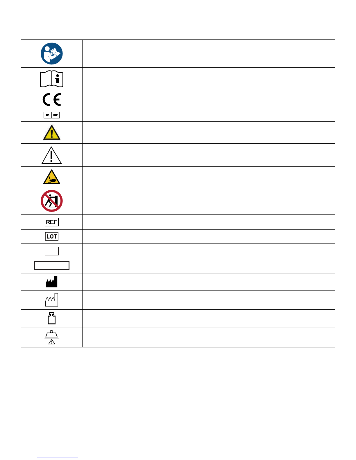
SSyymmbboollss
Refer to instruction manual/booklet
Operating instructions/Consult instructions for use
CE mark
EC REP
General warning
Caution
Warning; crushing of hands
No pushing
Catalogue number
Lot (batch) code
Serial number
For US Patents see www.stryker.com/patents
Manufacturer
Date of manufacture
Mass of equipment with safe working load
Safe working load
6086-209-001 Rev F.2 EN
Page 4

Page 5

TTaabbllee ooff CCoonntteennttss
Warning/Caution/Note Definition..............................................................................................................................3
Summary of safety precautions ................................................................................................................................4
Introduction ...............................................................................................................................................................7
Product description .................................................................................................................................................7
Indications for use...................................................................................................................................................7
Expected service life ...............................................................................................................................................8
Contraindications ....................................................................................................................................................8
Specifications .........................................................................................................................................................8
Standards with required options ...............................................................................................................................9
Product illustration ................................................................................................................................................ 10
Contact information ...............................................................................................................................................10
Serial number location...........................................................................................................................................11
Date of manufacture.............................................................................................................................................. 11
Setup....................................................................................................................................................................... 12
Installation...............................................................................................................................................................13
Installing the cot fastener ....................................................................................................................................... 13
Selecting the vehicle safety hook ...........................................................................................................................13
Vehicle configuration .............................................................................................................................................14
Positioning of the vehicle safety hook, front to back .................................................................................................15
Positioning of the vehicle safety hook, side to side...................................................................................................16
Installing the vehicle safety hook ............................................................................................................................17
Operation ................................................................................................................................................................ 19
Setting cot load height ........................................................................................................................................... 19
Operating guidelines ............................................................................................................................................. 19
Proper lifting techniques ........................................................................................................................................ 20
Transferring the patient to the cot ...........................................................................................................................20
Rolling the cot with a patient ..................................................................................................................................21
Raising or lowering the cot with two operators ......................................................................................................... 21
Raising or lowering the cot with one operator .......................................................................................................... 22
Loading or unloading a cot with the Power-LOAD option ..........................................................................................22
Loading a cot into a vehicle with an antler style cot fastener ..................................................................................... 23
Unloading a cot from a vehicle with an antler style cot fastener ................................................................................. 24
Positioning operators and helpers with the right hand release option .........................................................................25
Positioning operators and helpers with the left hand release option ...........................................................................25
Raising or lowering the backrest.............................................................................................................................25
Raising or lowering the siderails .............................................................................................................................26
Raising or lowering the siderails (XPS option) .........................................................................................................26
Extending the retractable head section ................................................................................................................... 26
Retracting the retractable head section...................................................................................................................27
Raising or lowering the footrest ..............................................................................................................................27
Raising or lowering the optional knee gatch ............................................................................................................27
Applying or releasing a wheel lock ..........................................................................................................................28
Applying or releasing the optional kickstand for dialysis scale...................................................................................28
Securing the patient with the G-rated restraint straps ............................................................................................... 29
Installing the shoulder, thigh, or ankle restraints.................................................................................................. 30
Installing the waist restraints..............................................................................................................................31
Adjusting restraint straps...................................................................................................................................31
Adding a restraint strap extension .......................................................................................................................... 32
Securing a patient with the X-restraint/RRUUGGGGEEDD™-X (6500-001-430/6506-001-430) restraint straps ......................... 32
Installing the X-restraint/RRUUGGGGEEDD-X shoulder restraints ....................................................................................33
Installing the X-restraint/RRUUGGGGEEDD-X waist restraints..........................................................................................34
Installing the X-restraint/RRUUGGGGEEDD-X thigh restraints ..........................................................................................34
Installing the X-restraint/RRUUGGGGEEDD-X ankle restraints .........................................................................................34
Installing the X-restraint/RRUUGGGGEEDD-X ankle restraints .........................................................................................35
Securing the patient with the Pedi-Mate® infant restraint system ..............................................................................35
6086-209-001 Rev F.2 1 EN
Page 6

Installing the defibrillator platform ........................................................................................................................... 36
Hanging equipment from the equipment hook ......................................................................................................... 38
Installing the head extension with pillow .................................................................................................................. 38
Positioning the two-stage IV pole ...........................................................................................................................38
Positioning the optional three-stage IV pole.............................................................................................................39
Attaching an oxygen bottle to the oxygen bottle holder.............................................................................................40
Attaching an oxygen bottle to the retractable head section oxygen bottle holder......................................................... 41
Installing the optional base storage net ...................................................................................................................41
Installing the backrest storage pouch......................................................................................................................42
Installing the optional head end storage flat............................................................................................................. 42
Transferring larger patients....................................................................................................................................43
Attaching the mattress...........................................................................................................................................43
Accessories ............................................................................................................................................................ 44
Cleaning and disinfecting with wipes...................................................................................................................... 45
Cleaning..................................................................................................................................................................46
Suggested cleaners ..............................................................................................................................................46
Preventive maintenance.........................................................................................................................................47
Regular inspection and adjustments .......................................................................................................................47
Every month or two hours .................................................................................................................................47
Every three months or six hours.........................................................................................................................47
Every six months or 12 hours ............................................................................................................................ 48
Every 12 months or 24 hours ............................................................................................................................. 49
Foot end fastener part replacement schedule .....................................................................................................49
EN 2 6086-209-001 Rev F.2
Page 7

WWaarrnniinngg//CCaauuttiioonn//NNoottee DDeeffiinniittiioonn
The words WWAARRNNIINNGG, CCAAUUTTIIOONN, and NNOOTTEE carry special meanings and should be carefully reviewed.
WWAARRNNIINNGG -- Alerts the reader about a situation which, if not avoided, could result in death or serious injury. It may also
describe potential serious adverse reactions and safety hazards.
CCAAUUTTIIOONN -- Alerts the reader of a potentially hazardous situation which, if not avoided, may result in minor or moderate
injury to the user or patient or damage to the product or other property. This includes special care necessary for the safe
and effective use of the device and the care necessary to avoid damage to a device that may occur as a result of use or
misuse.
NNoottee -- Provides special information to make maintenance easier or important instructions clearer.
6086-209-001 Rev F.2 3 EN
Page 8

SSuummmmaarryy ooff ssaaffeettyy pprreeccaauuttiioonnss
Always read and strictly follow the warnings and cautions listed on this page. Service only by qualified personnel.
WWAARRNNIINNGG
• Install the cot fastener by qualified personnel only. Improper installation could result in injury to the patient or operator.
• Always make sure that all cots meet the installation specifications for the Stryker cot fastener system.
• Failure to install the vehicle safety hook may cause injury to the patient or operator.
• Always have a certified mechanic, familiar with ambulance vehicle construction, install the safety hook.
• Always make sure that the cot safety bar connects with the vehicle safety hook before you remove the cot from the
vehicle patient compartment.
• Do not allow untrained assistants to assist in the operation of the product.
• Always follow proper hand placement on hand grips. Keep all hands clear of the red safety bar pivots when you load or
unload the cot or change cot height position.
• Do not ride on the base of the cot.
• Do not transport the cot sideways to avoid the risk of tipping. Always transport the cot in a lowered position, head end or
foot end first to minimize the risk of tipping.
• Always keep hands, fingers, and feet away from moving parts. Use caution when placing your hands and feet near the
base tubes while you raise or lower the cot.
• Always use all restraint straps to secure the patient on the product. An unrestrained patient may fall from the product and
be injured.
• Do not leave a patient unattended. Hold the product while a patient is on the product.
• Do not apply a wheel lock when a patient is on the product or when you move the product to avoid the risk of tipping.
• Do not use siderails as a patient restraint device.
• Always transport the cot at a lower height to reduce the risk of a cot tip. If possible, obtain additional assistance or take
an alternate route.
• Always avoid high obstacles, such as curbing, steps, or rough terrain to avoid the risk of the product tipping over.
• Always keep hands away from the foot end release handle when you raise or lower the cot with the side release handle.
• Always remove your foot from the base tube when you are lowering the cot to the lowest position.
• Always use PPoowweerr--LLOOAADD with the 6085/6086 PPeerrffoorrmmaannccee--PPRROO XT, 6500/6506 PPoowweerr--PPRROO XT, and 6510/6516
PPoowweerr--PPRROO IT cots with the PPoowweerr--LLOOAADD option only. In certain situations, you can use PPoowweerr--LLOOAADD as a standard
antler for most X-frame cots, but a rail clamp assembly is required for all cots without the PPoowweerr--LLOOAADD option.
• Always make sure that you use a PPoowweerr--LLOOAADD date of manufacture cot with the Stryker Model 6390 PPoowweerr--LLOOAADD
system to avoid the risk of injury.
• Always support the load of the patient, cot, and accessories after the weight is off of the ground.
• Two operators must be present when a cot is occupied.
• Always make sure that the safety bar connects with the vehicle safety hook before you remove the cot from the vehicle
patient compartment to avoid the risk of injury.
• Do not pull or lift on the cot safety bar when you unload the cot.
• Always lock the undercarriage before you remove the loading wheels from the vehicle patient compartment floor. An
unlocked undercarriage will not support the cot and injury to the patient or operator could result.
• Always lock the head section into place before you operate the cot.
• Do not load the cot into a vehicle with the head section retracted when using a cot fastener. The cot may tip or not
connect with the cot fastener.
• Do not install or apply a wheel lock on a product with worn wheels that are less than 6 in. diameter.
• Do not leave a patient or occupant unattended. Hold the product while a patient or occupant is on the product.
• Always use two people when using the kickstand.
• Always center the patient weight on the cot before you use the kickstand.
• Always apply the kickstand with your foot only.
• Always lower the cot height before you apply the kickstand for increased stability.
• Do not apply the kickstand during transport. Keep the kickstand in the retracted position.
• Do not use the kickstand as a brake.
EN 4 6086-209-001 Rev F.2
Page 9

• Do not apply the kickstand on a sloped surface.
• Always use all restraint straps to secure the patient on the cot. An unrestrained patient may fall from the cot.
• Do not attach restraint straps to the base tubes or cross tubes.
• Always locate the buckle away from obstructions or accessories on the cot to avoid the risk of accidental release of
PPeeddii--MMaattee® infant restraint system and injury to the infant.
• Do not pinch your fingers between the fowler bracket and the oxygen bottle if your cot is equipped with the optional
retractable head section oxygen bottle holder.
• Do not allow the head end storage flat (if equipped) to interfere with the operation of the retractable head section, safety
bar, or vehicle safety hook.
• Always use any appropriate personal protective equipment while power washing to avoid inhaling contagion. Power
washing equipment may aerate contamination.
• Always wipe the product with clean water and dry after cleaning. Some cleaning products are corrosive in nature and
may cause damage to the product. Failure to properly rinse and dry the product leaves a corrosive residue on the
surface of the product and may cause premature corrosion of critical components.
CCAAUUTTIIOONN
• Improper usage of the product can cause injury to the patient or operator. Operate the product only as described in this
manual.
• Do not modify the product or any components of the product. Modifying the product can cause unpredictable operation
resulting in injury to patient or operator. Modifying the product also voids its warranty.
• Always set the cot load height to the proper stop height before operation.
• Always have a certified mechanic, familiar with ambulance vehicle construction, install the vehicle safety hook. Consult
the vehicle manufacturer before you install the vehicle safety hook. Make sure that the installation of the vehicle safety
hook does not damage or interfere with the brake lines, oxygen lines, fuel lines, fuel tank, or electrical wiring of the
vehicle.
• Always set the cot load height before you place the cot into service.
• Always clear any obstacles that may interfere and cause injury to the operator or patient before operating the product.
• Do not allow the cot undercarriage to drop unassisted (commonly known as a hot drop) when you remove the cot from
the vehicle. Repeated hot dropping causes premature wear or damage to the cot.
• Do not sit or stand on the siderails (XPS option).
• Do not use the siderails (XPS option) as a patient transfer device or surface (for example, to slide a patient from the cot
to another surface).
• Do not position patients with full weight on the siderails (XPS option).
• Do not use the siderails (XPS option) as a push/pull device or to steer the product.
• Do not entangle the restraint straps in the base frame when you raise or lower the cot.
• Always secure the defibrillator platform to the product when you use the defibrillator platform.
• Always use and adjust the straps that are provided with the defibrillator platform to secure the defibrillator.
• Always change the installation location or adjust the straps for your specific defibrillator size or shape.
• Do not load the defibrillator platform above the safe working load of 30 lb (13.6 kg).
• Do not load the equipment hook above the safe working load of 35 lb (15.8 kg).
• Always remove all accessories or equipment from the equipment hook when in the vehicle.
• Do not load the IV pole above the safe working load of 25 lb (11.3 kg).
• Do not load the oxygen bottle holder above the safe working load of 15 lb (6.8 kg).
• Do not use two oxygen bottle holders at the same time.
• Do not use two head end oxygen bottle holders at the same time.
• Do not load the base storage net above the safe working load of 20 lb (9 kg).
• Always be careful when you retract the base to avoid damaging items that are stored in the base storage net.
• Do not load the backrest storage pouch above the safe working load of 20 lb (9 kg).
• Do not allow the storage pouch to interfere with the operation of the retractable head section.
• Do not load the head end storage flat above the safe working load of 40 lb (18 kg).
• Do not store items under the mattress. Items under the mattress may interfere with product operation.
• Do not steam clean or ultrasonically clean the product.
• Do not exceed 180 °F (82 °C) as the maximum water temperature.
6086-209-001 Rev F.2 5 EN
Page 10

• Do not exceed 1500 psi (130.5 bar) as the maximum water pressure. If you are using a hand held wand to wash the
product, keep the pressure nozzle at a minimum of 24 in. (61 cm) from the product.
• Always allow to air dry.
• Always remove the battery before you wash the cot.
• Do not clean, service, or perform maintenance while the product is in use.
• Always use authorized parts to avoid the risk of product damage.
EN 6 6086-209-001 Rev F.2
Page 11

IInnttrroodduuccttiioonn
This manual assists you with the operation or maintenance of your Stryker product. Read this manual before operating or
maintaining this product. Set methods and procedures to educate and train your staff on the safe operation or maintenance
of this product.
CCAAUUTTIIOONN
• Improper usage of the product can cause injury to the patient or operator. Operate the product only as described in this
manual.
• Do not modify the product or any components of the product. Modifying the product can cause unpredictable operation
resulting in injury to patient or operator. Modifying the product also voids its warranty.
NNoottee
• This manual is a permanent part of the product and should remain with the product even if the product is sold.
• Stryker continually seeks advancements in product design and quality. This manual contains the most current product
information available at the time of printing. There may be minor discrepancies between your product and this manual. If
you have any questions, contact Stryker Customer Service or Technical Support at 1-800-327-0770.
PPrroodduucctt ddeessccrriippttiioonn
The Stryker Model 6086 PPeerrffoorrmmaannccee--PPRROO™ XT is a manual ambulance cot that consists of a platform mounted on a
wheeled X-frame designed to support and transport a maximum weight of 700 lb (318 kg) in pre-hospital and hospital
environments.
The device is collapsible for use in emergency vehicles and has an adjustable load height feature to allow the device to be
set to different ambulance deck heights for proper body mechanics during loading and unloading. Duplicate foot end
controls on the upper and lower lift bars accommodate different operator positions or sizes and the side release handle
allows a single operator to raise and lower an unoccupied cot. The device is equipped with a retractable head section for
360-degree mobility in any height position, siderails, patient restraint straps, an adjustable pneumatic backrest, and various
optional accessories that assist with transport of the patient. Maximum patient comfort is attainable with the three different
litter positions of shock, flat leg, and optional knee gatch positioning.
IInnddiiccaattiioonnss ffoorr uussee
The Stryker PPeerrffoorrmmaannccee--PPRROO XT is a non-powered wheeled stretcher, which is intended to support and transport the
entire body of a traumatized, ambulatory, or non-ambulatory human patient (includes infants and adults).
The device is designed to support patients in a supine (horizontal) or sitting position and facilitate the transportation of
associated medical equipment (such as oxygen bottles, monitors, or pumps) in emergency or transport vehicles. This
ambulance cot is intended for use in pre-hospital and hospital environments, in emergency and non-emergency
applications. It is rated to a maximum capacity of 700 lb (318 kg) (sum of the patient, mattress and accessory weight) and
the intended operators of the device are trained professionals including emergency medical service and medical care
center personnel, as well as medical first responders. Ambulance cots are intended for transportation purposes.
PPeerrffoorrmmaannccee--PPRROO XT is not intended for extended stay or use as a hospital bed or in devices that modify air pressure,
such as hyperbaric chambers.
6086-209-001 Rev F.2 7 EN
Page 12

EExxppeecctteedd sseerrvviiccee lliiffee
PPeerrffoorrmmaannccee--PPRROO XT cot has a seven year expected service life under normal use conditions and with appropriate
periodic maintenance.
CCoonnttrraaiinnddiiccaattiioonnss
None known.
SSppeecciiffiiccaattiioonnss
Safe working load
700 lb 318 kg
NNoottee -- Safe working load
indicates the sum of the
patient, mattress and
accessory weight.
Backrest articulation/shock position 0° to 73°/+15°
Overall length/minimum length 80 in./64 in. 203 cm/163 cm
1
Height
Position 1 13.8 in. 35,1 cm
Position 2 22 in. 55,9 cm
Position 3 25.8 in. 66,5 cm
Position 4 28.1 in. 71,4 cm
Position 5 31.9 in. 81 cm
Position 6 34.6 in. 87,9 cm
Position 7 (low) 37.3 in. 94,7 cm
Position 8 (mid) 40 in. 101,6 cm
Position 9 (high) 42.2 in. 107,2 cm
Weight
2
89 lb 40,37 kg
Caster diameter/width 6 in./2 in. 15 cm/5 cm
Minimum operators required for loading/unloading an
occupied cot
Minimum operators required for loading/unloading an
unoccupied cot
Recommended fastener systems Model 6370 or 6377 Floor mount type, Model 6371 Wall
Recommended loading height
3
Single wheel lock/double wheel lock Optional
Standards
1
Height measured from bottom of mattress at seat section to ground level.
2
Cot is weighed with without mattress and restraints.
4
EN 8 6086-209-001 Rev F.2
2
1
mount type, Model 6390 PPoowweerr--LLOOAADD
Up to 34 in. Up to 86,4 cm
BS EN 1789, KKK-A-1822-F
Page 13

3
Set the load wheel height between 27.25 in. (69,2 cm) and 34 in. (86,4 cm).
Stryker reserves the right to change specifications without notice.
The PPeerrffoorrmmaannccee--PPRROO XT is designed to conform to the Federal Specification for the Star-of-Life Ambulance (KKK-A-
1822).
The PPeerrffoorrmmaannccee--PPRROO XT is designed to be compatible with competitive cot fastener systems.
The yellow and black color scheme is a proprietary trademark of Stryker Corporation.
SSttaannddaarrddss wwiitthh rreeqquuiirreedd ooppttiioonnss
To be compliant with the standards, you must install the following required options on your cot.
NNoottee -- Compatible cot is loaded into PPoowweerr--LLOOAADD in powered mode for crash testing.
OOppttiioonn sseelleeccttiioonn
SSttaannddaarrdd
SAE J3027 crash-test
standards with the use of a
crash-rated fastener
BS EN 1789:2007+A2:2014
crash-test standards with
the use of a crash-rated
fastener
RReessttrraaiinntt ppaacckkaaggee MMaattttrreessss OOppttiioonn
X-restraint package (6500001-430) or RUGGED-X
restraint package (6506001-430)
Knee gatch bolster mattress
(6500-002-150/6506-002-
150) or XPS mattress
(6500-003-130/6506-003-
130) (depending on cot
siderail)
G-rated restraint package
(6500-002-030), X-restraint
package (6500-001-430), or
RUGGED-X restraint
package (6506-001-430)
Knee gatch bolster mattress
(6500-002-150/6506-002-
150) or XPS mattress
(6500-003-130/6506-003-
130) (depending on cot
siderail)
6086-209-001 Rev F.2 9 EN
Page 14
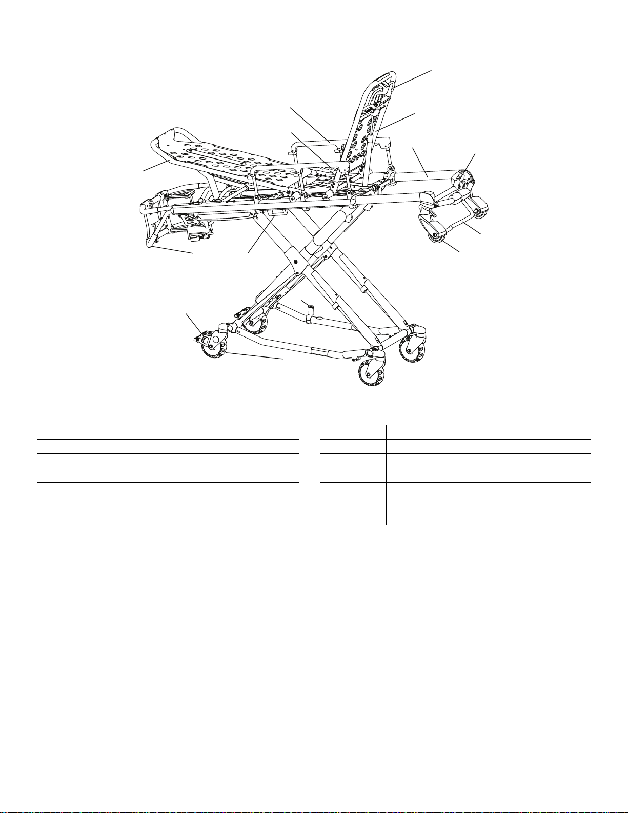
PPrroodduucctt iilllluussttrraattiioonn
A
B
C
D
F
H
K
L
M
G
I
J
N
E
FFiigguurree 11 –– PPrroodduucctt iilllluussttrraattiioonn
A Foot end release handle H Head section release
B Footrest I
C Siderail J
D Siderail release K Side release handle
E
F Backrest M
G Retractable head section N
Backrest adjustment handle
L
Safety bar
Loading wheel
Wheel lock (optional)
Cot retaining post
Transport wheel
CCoonnttaacctt iinnffoorrmmaattiioonn
Contact Stryker Customer Service or Technical Support at: 1-800-327-0770.
Stryker Medical
3800 E. Centre Avenue
Portage, MI 49002
USA
To view your operations or maintenance manual online, see https://techweb.stryker.com/.
Have the serial number (A) of your Stryker product available when calling Stryker Customer Service or Technical Support.
Include the serial number in all written communication.
EN 10 6086-209-001 Rev F.2
Page 15

SSeerriiaall nnuummbbeerr llooccaattiioonn
A
FFiigguurree 22 –– SSeerriiaall nnuummbbeerr llooccaattiioonn
DDaattee ooff mmaannuuffaaccttuurree
The year of manufacture is the first 2 digits of the serial number.
6086-209-001 Rev F.2 11 EN
Page 16

SSeettuupp
During setup, unpack the cartons and check all items for proper operation. Make sure that the product operates before you
place it into service.
Remove all shipping and packaging materials from the product before use.
The vehicle patient compartment where the product will be used must have a:
• Smooth rear edge for product loading
• Level floor large enough for the folded product
• Stryker cot fastener system
• Space to properly install the safety hook
NNoottee -- Loose items or debris on the patient compartment floor can interfere with the operation of the safety hook and
product fastener. Keep the patient compartment floor clear.
When necessary, modify the vehicle to fit the cot. Do not modify the cot.
EN 12 6086-209-001 Rev F.2
Page 17

IInnssttaallllaattiioonn
IInnssttaalllliinngg tthhee ccoott ffaasstteenneerr
The Stryker cot fastener systems are compatible only with cots that conform to the installation specifications.
WWAARRNNIINNGG
• Install the cot fastener by qualified personnel only. Improper installation could result in injury to the patient or operator.
• Always make sure that all cots meet the installation specifications for the Stryker cot fastener system.
NNoottee -- You may need to adjust the rail clamp assembly to compensate for any variation in the cot retaining post position
depending on the cot manufacturer and model number.
These instructions are intended for cots with antler style cot fastener systems. For crash-rated cot fasteners, see the
appropriate Operations Manual for installation instructions.
SSeelleeccttiinngg tthhee vveehhiiccllee ssaaffeettyy hhooookk
The vehicle safety hook is a device that ships with the cot. The cot safety bar and vehicle safety hook keep the cot from
being accidentally removed from the vehicle and provide increased operator assurance and confidence when loading and
unloading.
NNoottee -- These instructions are intended for cots with antler style cot fastener systems. For crash-rated cot fasteners, see the
appropriate Operations Manual for installation instructions. Crash-rated cot fasteners are shipped and installed with their
own vehicle safety hook, thus no additional hook is needed.
The vehicle safety hook was designed for compatibility and proper operation when loading and unloading the cot from a
vehicle that is compliant with Federal Regulation KKK-A-1822. Stryker offers three different types of vehicle safety hooks
that are ordered and shipped with your cot. These vehicle safety hook types meet the needs of various emergency vehicle
configurations, specifically the length and location of the floor structure support that is located in the rear of the vehicle.
To select which vehicle safety hook is appropriate for your vehicle configuration:
• Consider the location of the floor structure support where there is adequate room to mount the vehicle safety hook.
• Mount the vehicle safety hook into the back of the vehicle. Provide bumper clearance to allow the operators to load and
unload the cot from the vehicle.
• Note the differences in vehicle design. Each vehicle safety hook provides a different mounting location option to
maintain the appropriate distance between the face of the vehicle safety hook and the edge of the door sill.
Due to the differences in vehicle dimensions and the floor structure support locations, each vehicle safety hook allows for a
different mounting location. Select the correct position for your vehicle safety hook installation.
• Positioning of the vehicle safety hook, front to back
• Positioning of the vehicle safety hook, side to side
NNoottee -- When you replace an existing vehicle safety hook with a new style, adjust the mounting location to maintain the
proper position of the vehicle safety hook face.
6086-209-001 Rev F.2 13 EN
Page 18

6060-036-018
6092-036-018
6060-036-017
FFiigguurree 33 –– VVeehhiiccllee ssaaffeettyy hhooookk ttyyppeess
VVeehhiiccllee ccoonnffiigguurraattiioonn
CCAAUUTTIIOONN
• Always set the cot load height to the proper stop height before operation.
• Always have a certified mechanic, familiar with ambulance vehicle construction, install the vehicle safety hook. Consult
the vehicle manufacturer before you install the vehicle safety hook. Make sure that the installation of the vehicle safety
hook does not damage or interfere with the brake lines, oxygen lines, fuel lines, fuel tank, or electrical wiring of the
vehicle.
The cot is compatible with all vehicle deck heights that meet the Federal Specification for the Star-of-Life Ambulance KKKA-1822. See specifications for maximum load height.
According to Federal Specification for the Star-of-Life Ambulance KKK-A-1822:
• The rear of the ambulance shall be furnished with a sturdy, full-width, rear bumper, with step secured to the vehicle’s
chassis frame.
• The tread of the step shall have a minimum depth of 5 in. (13 cm) and a maximum depth of 10 in. (25 cm).
• If the step protrudes more than 7 in. (18 cm) from the rear of the vehicle, a fold-up step shall be furnished.
According to federal regulations (reference KKK-A-1822), the bumper height of the vehicle shall be installed equidistant 2
in. (± 5 cm) from the vehicle floor to the ground level, which is defined as the vehicle deck height. Installation of the vehicle
safety hook into any vehicle compliant with this federal specification provides adequate clearance for the cot base to lower
to its fully extended position.
EN 14 6086-209-001 Rev F.2
Page 19

DH
2
2
A
B
C D
E
F
A
B
FFiigguurree 44 –– DDeecckk aanndd bbuummppeerr hheeiigghhtt
A Deck height (DH)
B Bumper height
C Vehicle safety hook
D Sill edge
E Sill
F Bumper depth
PPoossiittiioonniinngg ooff tthhee vveehhiiccllee ssaaffeettyy hhooookk,, ffrroonntt ttoo bbaacckk
Check the front to back and side to side positioning when unloading and loading the cot to make sure that you install the
vehicle safety hook correctly.
To check the front to back positioning:
1. Select the appropriate vehicle safety hook (
2. Position the vehicle safety hook at least 3-3/4 in. from the leading edge of the door sill (A). The recommended distance
from the face of the safety hook to be no less than 3-3/4 in.
3. Make sure that you can secure the vehicle safety hook to the mount in the back of the vehicle.
4. Make sure that you have adequate bumper clearance to allow the cot to be loaded and unloaded from the vehicle.
5. Confirm the side to side placement of the vehicle safety hook (Positioning of the vehicle safety hook, side to side).
Selecting the vehicle safety hook
(page 13)).
6086-209-001 Rev F.2 15 EN
Page 20

6060-036-018
6060-036-017
6092-036-018
A
B
FFiigguurree 55 –– VVeehhiiccllee ssaaffeettyy hhooookk ppllaacceemmeenntt
A Sill
B Floor structure support
PPoossiittiioonniinngg ooff tthhee vveehhiiccllee ssaaffeettyy hhooookk,, ssiiddee ttoo ssiiddee
Before you install the vehicle safety hook, check the front to back and side to side positioning, when you unload and load
the cot.
To check the side to side positioning:
1. Remove the cot from the cot fastener and unload it from the vehicle.
2. Note the position of the cot load wheels and the cot safety bar when you are remove the cot.
3. Mark the center of the cot safety bar on the vehicle floor.
4. Make sure that the position marked in step 3 is where the cot safety bar connects with the vehicle safety hook every time
when you unload the cot in a variety of positions (such as all the way to the left and all the way to the right).
NNoottee
• If the cot safety bar does not connect with the vehicle safety hook in any of these positions (left, center, or right),
modify the vehicle. Do not modify the cot or the vehicle safety hook.
• If the cot safety bar connects with vehicle safety hook every time, install the vehicle safety hook.
EN 16 6086-209-001 Rev F.2
Page 21

IInnssttaalllliinngg tthhee vveehhiiccllee ssaaffeettyy hhooookk
Before installing the vehicle safety hook, the certified mechanic should plan for the placement of the vehicle safety hook in
the rear of the vehicle patient compartment.
WWAARRNNIINNGG
• Failure to install the vehicle safety hook may cause injury to the patient or operator.
• Always have a certified mechanic, familiar with ambulance vehicle construction, install the safety hook.
• Always make sure that the cot safety bar connects with the vehicle safety hook before you remove the cot from the
vehicle patient compartment.
HHaarrddwwaarree rreeqquuiirreedd ((nnoott ssuupppplliieedd))::
• (2) Grade 5, minimum 1/4”-20 socket head cap screws * for the short vehicle safety hook or long vehicle safety hook
• (2) Grade 5, minimum 1/4”-20 flat socket head cap screws * for the J vehicle safety hook
• (2) Flat washers
• (2) Lock washers
• (2) 1/4”-20 nuts
NNoottee -- The length of the socket head cap screws depend on the thickness of the vehicle floor. Use screws that are long
enough to go completely through the vehicle patient compartment floor, washer, and nut, with at least two full threads in the
nut.
1. Determine the correct vehicle safety hook front to back and side to side positioning, so the cot safety bar connects to the
vehicle safety hook every time.
• Positioning of the vehicle safety hook, front to back
• Positioning of the vehicle safety hook, side to side
2. Drill the holes for the screws.
3. Fasten the vehicle safety hook to the vehicle patient compartment floor.
4. Make sure that the cot safety bar connects with the vehicle safety hook before you remove the cot from the vehicle
patient compartment.
6086-209-001 Rev F.2 17 EN
Page 22
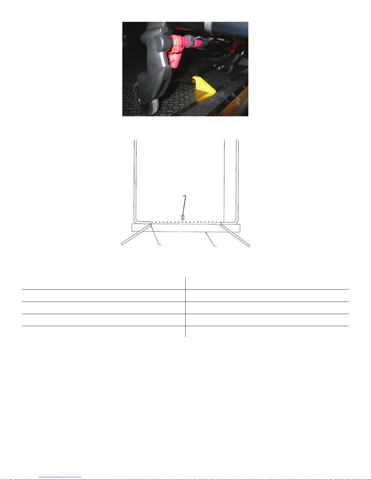
FFiigguurree 66 –– SSaaffeettyy bbaarr sseeccuurreedd iinn tthhee vveehhiiccllee ssaaffeettyy hhooookk
A
B
C
DE
FFiigguurree 77 –– VVeehhiiccllee ssaaffeettyy hhooookk ppllaacceemmeenntt
A Top view of vehicle
B Vehicle safety hook
C Squad bench
D Bumper
E Door frame
After installation, make sure that the cot legs lock into the load position without contacting the vehicle bumper.
EN 18 6086-209-001 Rev F.2
Page 23

OOppeerraattiioonn
SSeettttiinngg ccoott llooaadd hheeiigghhtt
CCAAUUTTIIOONN -- Always set the cot load height before you place the cot into service.
Adjust the cot load height to match the vehicle deck. If the cot does not line up correctly, you may also adjust the cot load
height.
To set the cot load height:
1. Roll the cot the loading area of your vehicle.
2. Compare the difference between the deck height of the vehicle and the load height of the cot.
3. Select high, mid, or low depending on the cot load height requirements.
FFiigguurree 88 –– SSeett ddeessiirreedd ccoott llooaadd hheeiigghhtt
CCoott llooaadd hheeiigghhtt FFoorr ddeecckk hheeiigghhttss
High Above 32 in.
Mid Between 30-32 in.
Low Below 30 in.
4. Make sure that the cot safety bar connects with the vehicle safety hook every time when you unload the cot in a variety
of positions. If the cot safety bar misses the vehicle safety hook, select the next lower height setting.
OOppeerraattiinngg gguuiiddeelliinneess
WWAARRNNIINNGG
• Do not allow untrained assistants to assist in the operation of the product.
• Always follow proper hand placement on hand grips. Keep all hands clear of the red safety bar pivots when you load or
unload the cot or change cot height position.
• Do not ride on the base of the cot.
• Do not transport the cot sideways to avoid the risk of tipping. Always transport the cot in a lowered position, head end or
foot end first to minimize the risk of tipping.
• Always keep hands, fingers, and feet away from moving parts. Use caution when placing your hands and feet near the
base tubes while you raise or lower the cot.
6086-209-001 Rev F.2 19 EN
Page 24

CCAAUUTTIIOONN -- Always clear any obstacles that may interfere and cause injury to the operator or patient before operating the
product.
• Operate the product only as described in this manual.
• Read all labels and instructions on the product before use.
• Practice changing height positions and loading the cot until you fully understand the operation of the product.
• Always load or unload an occupied cot with a minimum of two trained operators. Two operators must be present when a
cot is occupied. Stryker recommends that both operators are at the foot end to reduce the load on each operator. One or
two operators can lift from the foot end of the cot.
• Do not adjust, roll, or load the cot into a vehicle without advising the patient. Stay with the patient and control the product
at all times.
• You can transport the cot in any position. Stryker recommends that the operators transport the patient in the lowest
comfortable position to maneuver the cot.
• Only use the wheel locks during patient transfer or without a patient on the product.
• Do not apply a wheel lock when an occupant is on the product or when moving the product to avoid the risk of tipping.
• Always use all restraint straps to secure the patient on the product. An unrestrained patient may fall from the product.
• Use properly trained helpers to control the cot, when necessary.
PPrrooppeerr lliiffttiinngg tteecchhnniiqquueess
When you lift the product and occupant, follow these proper lifting techniques to avoid the risk of injury:
• Keep your hands close to your body
• Keep your back straight
• Coordinate all movement with your partner
• Lift with your legs
• Avoid twisting
TTrraannssffeerrrriinngg tthhee ppaattiieenntt ttoo tthhee ccoott
WWAARRNNIINNGG
• Always use all restraint straps to secure the patient on the product. An unrestrained patient may fall from the product and
be injured.
• Do not leave a patient unattended. Hold the product while a patient is on the product.
• Do not apply a wheel lock when a patient is on the product or when you move the product to avoid the risk of tipping.
• Do not use siderails as a patient restraint device.
To transfer the patient to the product:
1. Roll the product to the patient (Rolling the cot with a patient).
2. Place the product beside the patient and raise or lower the product to the level of the patient.
3. Lower the siderails and open the restraint straps.
4. Transfer the patient to the product. Follow accepted EMS procedures.
5. Secure the patient to the product with all of the restraint straps.
6. Raise the siderails and adjust the backrest and footrest as necessary.
NNoottee -- Use the Transfer Flat (6005-001-001) to transfer larger patients.
EN 20 6086-209-001 Rev F.2
Page 25

RRoolllliinngg tthhee ccoott wwiitthh aa ppaattiieenntt
WWAARRNNIINNGG
• Always transport the cot at a lower height to reduce the risk of a cot tip. If possible, obtain additional assistance or take
an alternate route.
• Always avoid high obstacles, such as curbing, steps, or rough terrain to avoid the risk of the product tipping over.
To roll the cot with a patient:
1. Position one operator at the foot end and one operator at the head end of the cot.
2. Make sure that the litter is perpendicular when you approach door sills or other low obstacles.
3. Lift each set of wheels over the door sill or obstacle separately.
RRaaiissiinngg oorr lloowweerriinngg tthhee ccoott wwiitthh ttwwoo ooppeerraattoorrss
Always raise or lower an occupied cot with a minimum of two trained operators. Two operators must be present when a cot
is occupied. Operators must be able to lift the total weight of the patient, cot, and any items on the cot.
WWAARRNNIINNGG
• Always keep hands, fingers, and feet away from moving parts. Use caution when placing your hands and feet near the
base tubes while you raise or lower the cot.
• Always follow proper hand placement on hand grips. Keep all hands clear of the red safety bar pivots when you load or
unload the cot or change cot height position.
• Always keep hands away from the foot end release handle when you raise or lower the cot with the side release handle.
To raise or lower the cot:
From the head end and foot end From the left side and right side
1. Operator 1 (at the foot end): Squeeze the release
handle with a secure grip on the lifting bars.
2. Both operators:
2.1. Lift the foot end of the cot until you lift the weight
off of the latching mechanism.
2.2. Operator 1 (at the foot end): Squeeze and hold
the release handle while both operators raise or
lower the cot together.
2.3. Operator 1 (at the foot end): Release the release
handle when you reach the desired height.
2.4. Maintain a secure grip on the litter frame until the
latching mechanism locks into place.
1. Check the cot to determine if the side release handle is
on the patient left or patient right side.
2. Operator 1 (on the side with the release handle): Reach
the release handle at the midpoint of the litter.
3. Both operators:
3.1. Lift the foot end of the cot until you lift the weight
off of the latching mechanism (approximately 1/
4”).
3.2. Operator 1 (on the side with the release handle):
Squeeze and hold the release handle.
3.3. Raise or lower the cot.
3.4. Operator 1 (on the side with the release handle):
Release the release handle when you reach the
desired height.
3.5. Maintain a secure grip on the litter frame until the
latching mechanism locks into place.
6086-209-001 Rev F.2 21 EN
Page 26

RRaaiissiinngg oorr lloowweerriinngg tthhee ccoott wwiitthh oonnee ooppeerraattoorr
You can raise or lower an unoccupied cot into a vehicle with one operator.
WWAARRNNIINNGG
• Always keep hands, fingers, and feet away from moving parts. Use caution when placing your hands and feet near the
base tubes while you raise or lower the cot.
• Always follow proper hand placement on hand grips. Keep all hands clear of the red safety bar pivots when you load or
unload the cot or change cot height position.
• Always remove your foot from the base tube when you are lowering the cot to the lowest position.
• Always keep hands away from the foot end release handle when you raise or lower the cot with the side release handle.
To raise or lower the cot:
From the foot end From the side
1. Grasp the lower foot end lift tube.
2. Tip the cot up on its load wheels.
3. Squeeze and hold the release handle and raise or lower
the cot.
4. Release the release handle when you reach the desired
height.
5. Lower the cot back on onto the four base wheels.
1. Place one foot on the outer base tube.
2. Grasp the side release handle with one hand. Place
your other hand on the outer support rail to stabilize the
cot.
3. Squeeze and hold the release handle and raise or lower
the cot.
4. Release the release handle when you reach the desired
height.
LLooaaddiinngg oorr uunnllooaaddiinngg aa ccoott wwiitthh tthhee PPoowweerr--LLOOAADD ooppttiioonn
The cot is fully compatible with the Model 6390 PPoowweerr--LLOOAADD system if you ordered the cot with the PPoowweerr--LLOOAADD option
or upgraded your cot with the compatibility kit.
WWAARRNNIINNGG
• Always use PPoowweerr--LLOOAADD with the 6085/6086 PPeerrffoorrmmaannccee--PPRROO XT, 6500/6506 PPoowweerr--PPRROO XT, and 6510/6516
PPoowweerr--PPRROO IT cots with the PPoowweerr--LLOOAADD option only. In certain situations, you can use PPoowweerr--LLOOAADD as a standard
antler for most X-frame cots, but a rail clamp assembly is required for all cots without the PPoowweerr--LLOOAADD option.
• Always make sure that you use a PPoowweerr--LLOOAADD date of manufacture cot with the Stryker Model 6390 PPoowweerr--LLOOAADD
system to avoid the risk of injury.
CCoott CCoommppaattiibbiilliittyy kkiitt
Model 6506 PPoowweerr--PPRROO XT 6506-700-001
Model 6516 PPoowweerr--PPRROO IT 6516-700-001
Model 6086 PPeerrffoorrmmaannccee--PPRROO XT 6086-700-001
For more information about using your PPoowweerr--LLOOAADD compatible cot, see the PPoowweerr--LLOOAADD Operations Manual.
EN 22 6086-209-001 Rev F.2
Page 27

LLooaaddiinngg aa ccoott iinnttoo aa vveehhiiccllee wwiitthh aann aannttlleerr ssttyyllee ccoott ffaasstteenneerr
Always load an occupied cot with a minimum of two trained operators. Two operators must be present when a cot is
occupied. Operators must be able to lift the total weight of the patient, cot, and any items on the cot.
WWAARRNNIINNGG
• Always support the load of the patient, cot, and accessories after the weight is off of the ground.
• Two operators must be present when a cot is occupied.
• Always follow proper hand placement on hand grips. Keep all hands clear of the red safety bar pivots when you load or
unload the cot or change cot height position.
The higher an operator must lift the cot, the more difficult it may be to hold the weight. The operator must be able to lift the
cot high enough for the cot legs to extend when the cot is unloaded. An operator may need help if they are too short or if the
patient is too heavy to lift when unloading the cot. If you are a shorter operator, you may need to raise your arms higher to
allow the cot legs to extend.
NNoottee -- You can load an unoccupied cot into a vehicle with one operator.
To load the cot into a vehicle:
1. Place the cot in a loading position. A loading position is any position where the load wheels meet the vehicle floor height.
2. Lift the vehicle bumper, if equipped, to the raised position.
3. Roll the cot to the open door of the vehicle patient compartment.
4. Push the cot forward until the load wheels are on the vehicle patient compartment floor and the cot safety bar passes
the vehicle safety hook.
5. Pull the cot back until the cot safety bar connects to the vehicle safety hook for maximum clearance to lift the base.
6. Make sure that the cot safety bar connects with the vehicle safety hook.
7. Load the cot.
With one operator at the foot end and one operator on the
side
a. Operator 1 (at the foot end):
i. Grasp the cot frame at the foot end.
ii. Lift the foot end of the cot until you lift the weight
off of the latching mechanism.
Squeeze and hold the release handle.
b. Operator 2 (on the side):
i. Grasp the cot outer rail to stabilize the cot.
ii. Grasp the base frame.
iii. After the foot end operator lifts the cot and
squeezes the release handle, raise the
undercarriage until it stops in the uppermost
position and hold it there.
iv. The foot end operator should release the handle to
lock the base in the retracted position.
8. Push the cot into the vehicle patient compartment.
9. Make sure that the cot is secured in the cot fastener (not included).
With one operator (when loading an unoccupied cot)
a. Grasp the cot frame at the foot end and squeeze and
hold the release handle.
b. Lower the foot end of the cot to the ground.
c. Lift the foot end of the cot until it is level with the
compartment floor.
d. Grasp the base of the cot with one hand and pull up
the base of the cot towards the litter, reducing the
space between the base and the litter.
6086-209-001 Rev F.2 23 EN
Page 28

UUnnllooaaddiinngg aa ccoott ffrroomm aa vveehhiiccllee wwiitthh aann aannttlleerr ssttyyllee ccoott ffaasstteenneerr
Always unload an occupied cot with a minimum of two trained operators. Two operators must be present when a cot is
occupied. Operators must be able to lift the total weight of the patient, cot, and any items on the cot.
WWAARRNNIINNGG
• Always support the load of the patient, cot, and accessories after the weight is off of the ground.
• Two operators must be present when a cot is occupied.
• Always follow proper hand placement on hand grips. Keep all hands clear of the red safety bar pivots when you load or
unload the cot or change cot height position.
• Always make sure that the safety bar connects with the vehicle safety hook before you remove the cot from the vehicle
patient compartment to avoid the risk of injury.
• Do not pull or lift on the cot safety bar when you unload the cot.
• Always lock the undercarriage before you remove the loading wheels from the vehicle patient compartment floor. An
unlocked undercarriage will not support the cot and injury to the patient or operator could result.
CCAAUUTTIIOONN
• Do not allow the cot undercarriage to drop unassisted (commonly known as a hot drop) when you remove the cot from
the vehicle. Repeated hot dropping causes premature wear or damage to the cot.
NNoottee -- You can unload an unoccupied cot from a vehicle with one operator.
To unload the cot from a vehicle:
1. Lift the vehicle bumper, if equipped, to the raised position.
2. Remove the cot from the cot fastener.
3. Unload the cot.
With one operator at the foot end and one operator on the
side
a. Operator 1: Grasp the cot frame at the foot end. Pull
the cot out of the vehicle patient compartment until the
safety bar connects with the vehicle safety hook.
b. Operator 2: Make sure that the safety bar connects
with the vehicle safety hook. Grasp the base frame, lift
slightly, and lower the base frame to its fully extended
position while operator 1 squeezes and holds the
release handle.
c. Operator 1: Let go of the release handle and make
sure that the undercarriage locks into place. Set the
cot onto the ground.
d. Operator 2: Push the cot safety bar release lever
forward to remove the cot safety bar from the vehicle
safety hook.
4. Remove the load wheels from the vehicle patient compartment floor.
5. Place the cot in any position, except full down for rolling.
With one operator (when unloading an unoccupied cot)
a. Grasp the cot frame at the foot end.
b. Pull the cot out of the vehicle patient compartment
until the safety bar connects with the vehicle safety
hook.
c. Lower the foot end of the cot to the ground.
d. Squeeze and hold the release handle and raise the
foot end of the cot back to a level position with the
vehicle patient compartment floor.
e. Push the cot safety bar release lever forward to
remove the cot safety bar from the vehicle safety
hook.
EN 24 6086-209-001 Rev F.2
Page 29

PPoossiittiioonniinngg ooppeerraattoorrss aanndd hheellppeerrss wwiitthh tthhee rriigghhtt hhaanndd rreelleeaassee ooppttiioonn
H
H
O
O
H
H
O
O
O
O
H H
H H
H HOOO O
H
H H
H
H H
H
H OO
H
H
O
O
H
H
O
O
O
OH
H
H
H
H H
O O
O
OH
H H
H
H
H
H
H O
O
CChhaannggiinngg lleevveellss RRoolllliinngg LLooaaddiinngg aanndd uunnllooaaddiinngg
Two operators (O)
Two helpers (H)
Two operators (O)
Four helpers (H)
PPoossiittiioonniinngg ooppeerraattoorrss aanndd hheellppeerrss wwiitthh tthhee lleefftt hhaanndd rreelleeaassee ooppttiioonn
CChhaannggiinngg lleevveellss RRoolllliinngg LLooaaddiinngg aanndd uunnllooaaddiinngg
Two operators (O)
Two helpers (H)
Two operators (O)
Four helpers (H)
RRaaiissiinngg oorr lloowweerriinngg tthhee bbaacckkrreesstt
To raise the backrest, squeeze the backrest adjustment handle to move the backrest to the desired height.
To lower the backrest, squeeze the backrest adjustment handle while you push down on the backrest to the desired height.
6086-209-001 Rev F.2 25 EN
Page 30

RRaaiissiinngg oorr lloowweerriinngg tthhee ssiiddeerraaiillss
Always lower the siderails when you transfer a patient to the cot or from the cot.
WWAARRNNIINNGG -- Do not use siderails as a patient restraint device.
To raise the siderails, lift up on the siderail until the latch clicks and the siderail locks into place. Always keep the siderails in
the raised position unless you are transferring the patient.
To lower the siderails, squeeze the siderail release handle to release the siderail latch. Guide the siderail down toward the
foot end of the cot until the siderail lays flat. Always lower the siderails when you transfer a patient to or from the cot.
RRaaiissiinngg oorr lloowweerriinngg tthhee ssiiddeerraaiillss ((XXPPSS ooppttiioonn))
You can order your cot with the expandable patient surface (XPS) option or upgrade your cot to add the XPS option.
WWAARRNNIINNGG -- Do not use siderails as a patient restraint device.
CCAAUUTTIIOONN
• Do not sit or stand on the siderails (XPS option).
• Do not use the siderails (XPS option) as a patient transfer device or surface (for example, to slide a patient from the cot
to another surface).
• Do not position patients with full weight on the siderails (XPS option).
• Do not use the siderails (XPS option) as a push/pull device or to steer the product.
Siderails (XPS option) attach to the cot and are always available for your use. The siderails (XPS option) adjust according
to patient size and lock into seven positions. The siderails also adjust to fit through standard doorways or elevators.
To raise the siderails, lift up on the siderail until it locks into the desired position.
To lower the siderails, lift up to relieve the weight, then pull the red lever. Always lower the siderails when you transfer a
patient to or from the cot.
The XPS option is not a primary patient support surface. It includes a wider mattress and is intended to enhance patient
comfort.
EExxtteennddiinngg tthhee rreettrraaccttaabbllee hheeaadd sseeccttiioonn
Extend the retractable head section before you load the cot into the vehicle patient compartment.
WWAARRNNIINNGG
• Always lock the head section into place before you operate the cot.
• Do not load the cot into a vehicle with the head section retracted when using a cot fastener. The cot may tip or not
connect with the cot fastener.
To extend the retractable head section:
1. Grasp the outer rail with one hand for support and pull the head section release handle. Rotate the head section release
handle toward the head end of the cot to release the head section from the locked position.
2. While you hold the head section release handle in the released position, pull the head section away from the litter frame.
Lengthen the head section to the extended position.
3. Release the head section release handle to lock the head section in the extended position.
EN 26 6086-209-001 Rev F.2
Page 31

RReettrraaccttiinngg tthhee rreettrraaccttaabbllee hheeaadd sseeccttiioonn
Retract the retractable head section to roll the cot in any direction on the load wheels for improved mobility and
maneuverability, even in the lowest position.
WWAARRNNIINNGG
• Always lock the head section into place before you operate the cot.
• Do not load the cot into a vehicle with the head section retracted when using a cot fastener. The cot may tip or not
connect with the cot fastener.
To retract the retractable head section:
1. Grasp the outer rail with one hand for support and release the head section release handle. Rotate the head section
release handle toward the head end of the cot to release the head section from the locked position.
2. While you hold the head section release handle in the released position, push the head section toward the litter frame.
Retract the head section to the retracted position.
3. Release the head section release handle to lock the head section in the retracted position.
RRaaiissiinngg oorr lloowweerriinngg tthhee ffoooottrreesstt
You can adjust the footrest to elevate the patient’s legs.
To raise the footrest, lift the frame as high as possible. The support bracket automatically secures the frame when you
release the footrest.
To lower the footrest, lift the frame and lift up on the footrest release handle until the frame releases the support bracket.
Lower the footrest until it lays flat.
RRaaiissiinngg oorr lloowweerriinngg tthhee ooppttiioonnaall kknneeee ggaattcchh
To raise the optional knee gatch:
1. Lift either of the red lifting loops (A) until the knee gatch is in the highest position (Figure 9).
2. Lower the knee gatch to secure the support bracket to the locking mechanism.
3. Make sure that the locking mechanism is secure before you release the lifting loop.
To lower the knee gatch, lift either of the red lifting loops (A) to relieve pressure on the locking mechanism, and while
holding the loop, push on the red footrest release handle (B) until the support bracket is released. Lower the knee gatch
until it lays flat.
To raise the knee gatch in trend, lift the footrest frame (C) as high as possible until the frame locks into place. The support
bracket automatically connects when you release the frame.
To lower the knee gatch in trend, lift the footrest frame (C), and while holding the frame, lift up on the red footrest release
handle (B) until the frame releases the support bracket. Lower the footrest until it lays flat.
6086-209-001 Rev F.2 27 EN
Page 32

A
B
C
FFiigguurree 99 –– GGaattcchh
AAppppllyyiinngg oorr rreelleeaassiinngg aa wwhheeeell lloocckk
WWAARRNNIINNGG
• Do not apply a wheel lock when a patient is on the product or when you move the product to avoid the risk of tipping.
• Do not install or apply a wheel lock on a product with worn wheels that are less than 6 in. diameter.
• Do not leave a patient or occupant unattended. Hold the product while a patient or occupant is on the product.
To apply a wheel lock, press down on the pedal until it stops and is resting against the surface of the wheel.
To release a wheel lock, press down on the top of the pedal with your foot or lift up on the pedal with your toe. The top of the
pedal will rest against the caster frame when you release the wheel lock.
NNoottee -- Wheel locks help prevent the product from rolling while unattended. Wheel locks may not provide sufficient
resistance on all surfaces or under loads.
AAppppllyyiinngg oorr rreelleeaassiinngg tthhee ooppttiioonnaall kkiicckkssttaanndd ffoorr ddiiaallyyssiiss ssccaallee
Use the kickstand to weigh patients on a scale.
WWAARRNNIINNGG
• Always use two people when using the kickstand.
• Always center the patient weight on the cot before you use the kickstand.
• Always apply the kickstand with your foot only.
• Always lower the cot height before you apply the kickstand for increased stability.
• Do not apply the kickstand during transport. Keep the kickstand in the retracted position.
• Do not use the kickstand as a brake.
• Do not apply the kickstand on a sloped surface.
NNoottee -- The optional kickstand (6085-102-000) is not compatible with the optional base storage net (6500-160-000).
To apply the kickstand:
1. Operator 1: Apply the kickstand with your foot.
2. Operator 2: Lift the foot end of the cot to actuate the kickstand.
3. Both operators: Make sure that the kickstand is in the forward locked position.
To release the kickstand, Operator 1 lifts the foot end of the cot until both wheels are off the floor. Operator 2 rolls the cot
forward to make sure that the kickstand retracts.
EN 28 6086-209-001 Rev F.2
Page 33

SSeeccuurriinngg tthhee ppaattiieenntt wwiitthh tthhee GG--rraatteedd rreessttrraaiinntt ssttrraappss
WWAARRNNIINNGG
• Always use all restraint straps to secure the patient on the cot. An unrestrained patient may fall from the cot.
• Do not attach restraint straps to the base tubes or cross tubes.
CCAAUUTTIIOONN -- Do not entangle the restraint straps in the base frame when you raise or lower the cot.
NNoottee -- Restraint straps are a Type BF applied part.
Secure restraint straps to the cot in the required attachment locations (Figure 10). Restraint strap attachment locations
should provide strong anchorage and proper restraint position. Do not allow restraint straps to interfere with equipment or
accessories. Buckle the restraint straps across the patient’s shoulders, waist, and legs. Buckle restraint straps when the cot
is not in use.
6086-209-001 Rev F.2 29 EN
Page 34

FFiigguurree 1100 –– RReessttrraaiinntt ssttrraapp aattttaacchhmmeenntt ppooiinnttss
IInnssttaalllliinngg tthhee sshhoouullddeerr,, tthhiigghh,, oorr aannkkllee rreessttrraaiinnttss
To install the shoulder, thigh, or ankle restraints:
1. Wrap the restraint strap around the cot frame.
2. Push the restraint strap buckle through the loop.
3. Pull the buckle around the loop to secure the restraint strap to the cot.
EN 30 6086-209-001 Rev F.2
Page 35

FFiigguurree 1111 –– WWrraapp tthhee rreessttrraaiinntt ssttrraapp
aarroouunndd tthhee ccoott ffrraammee
FFiigguurree 1122 –– PPuusshh tthhee rreessttrraaiinntt ssttrraapp
bbuucckkllee tthhrroouugghh tthhee lloooopp
FFiigguurree 1133 –– SSeeccuurree tthhee rreessttrraaiinntt
ssttrraapp ttoo tthhee ccoott
IInnssttaalllliinngg tthhee wwaaiisstt rreessttrraaiinnttss
To install the waist restraints:
1. Wrap the restraint strap around the cot frame.
2. Push both buckles through the loop for the double buckle strap.
3. Push the buckle and the tongue through the loop for the tongue and buckle strap.
4. Pull the buckle through the loop to secure the restraint strap to the cot.
NNoottee -- The waist restraint must form an X with the restraint strap at the shoulder.
AAddjjuussttiinngg rreessttrraaiinntt ssttrraappss
Open the restraint straps and place them at either side of the cot while you position the patient on the cot mattress.
Lengthen the restraint straps, buckle them around the patient, and shorten them to tighten.
• To open the restraint strap, press the red button on the front of the buckle receiver. This allows you to release the buckle
latch plate and pull it out of the receiver.
• To close the restraint strap, push the latch plate into the receiver until you hear a click.
• To lengthen the restraint strap, grasp the buckle latch plate, turn it at an angle to the webbing, then pull it out. A hemmed
tab at the end of the webbing prevents the latch plate from coming off of the strap.
• To shorten the restraint strap, grasp the hemmed tab and pull the webbing back through the latch plate to tighten.
When you buckle a restraint strap around a patient, secure the latch plate and remove any loose webbing from the cot.
Inspect the restraint straps at least once a month (more if used often). Check for a bent or broken receiver or latch plate, or
torn or frayed webbing. Replace any worn or inoperable restraint strap.
6086-209-001 Rev F.2 31 EN
Page 36

FFiigguurree 1166 –– SShhoorrtteenn tthhee rreessttrraaiinntt
ssttrraapp
FFiigguurree 1144 –– BBuucckkllee tthhee ssttrraappss
aarroouunndd tthhee ppaattiieenntt
FFiigguurree 1155 –– LLeennggtthheenn tthhee rreessttrraaiinntt
ssttrraapp
AAddddiinngg aa rreessttrraaiinntt ssttrraapp eexxtteennssiioonn
Add a restraint strap extension (6082-160-050) for extra length when you buckle the lap belt around larger patients.
FFiigguurree 1177 –– RReessttrraaiinntt ssttrraapp eexxtteennssiioonn
SSeeccuurriinngg aa ppaattiieenntt wwiitthh tthhee XX--rreessttrraaiinntt//RRUUGGGGEEDD™--XX ((66550000--000011--443300//66550066--000011--
443300)) rreessttrraaiinntt ssttrraappss
Secure restraint straps to the cot in the required attachment locations: shoulders waist, thighs, and ankles.
WWAARRNNIINNGG
• Always use all restraint straps to secure the patient on the cot. An unrestrained patient may fall from the cot.
• Do not attach restraint straps to the base tubes or cross tubes.
CCAAUUTTIIOONN -- Do not entangle the restraint straps in the base frame when you raise or lower the cot.
NNoottee -- Restraint straps are a Type BF applied part.
Restraint strap attachment locations should provide strong anchorage and proper restraint position (Figure 18). Do not
allow restraint straps to interfere with equipment or accessories. Buckle the restraints across the shoulders, waist, thighs,
and ankles. Buckle all restraint straps when the cot is not in use.
1. Installing the X-restraint/RRUUGGGGEEDD-X shoulder restraints
2. Installing the X-restraint/RRUUGGGGEEDD-X waist restraints
3. Installing the X-restraint/RRUUGGGGEEDD-X thigh restraints
4. Installing the X-restraint/RRUUGGGGEEDD-X ankle restraints
5. Installing the X-restraint/RRUUGGGGEEDD-X ankle restraints
EN 32 6086-209-001 Rev F.2
Page 37

1
2
4
3
FFiigguurree 1188 –– RReessttrraaiinntt ssttrraapp aattttaacchhmmeenntt llooccaattiioonnss
IInnssttaalllliinngg tthhee XX--rreessttrraaiinntt//RRUUGGGGEEDD--XX sshhoouullddeerr rreessttrraaiinnttss
To install the X-restraint/RRUUGGGGEEDD-X shoulder restraints:
1. Wrap the restraint around the cot frame.
2. Pull the restraint buckle through the loop, toward the head end of the cot.
3. Feed the buckle under the XPS System.
4. For the Model 6506 Power-PRO XT cot and Model 6086 Performance-PRO XT cot, pull the restraint tight and toward
the back of the backrest.
5. For the Model 6550 Power-PRO TL cot, pull the restraint under the cross tube and toward the back of the backrest.
6. Feed the buckle through the opening in the backrest.
7. Connect the patient right shoulder buckle to the patient left waist buckle.
6086-209-001 Rev F.2 33 EN
Page 38

1 2 3 4 5 6
FFiigguurree 1199 –– SShhoouullddeerr rreessttrraaiinnttss
1 2 3 4 5
1 2 3 4
IInnssttaalllliinngg tthhee XX--rreessttrraaiinntt//RRUUGGGGEEDD--XX wwaaiisstt rreessttrraaiinnttss
To install the X-restraint/RRUUGGGGEEDD-X waist restraints:
1. Wrap the restraint around the cot frame.
2. Pull the restraint buckles through the loop, toward the head end of the cot.
3. Feed the buckle under the XPS System.
4. Pull the buckles tight. One restraint should angle toward the head end and one should lay straight across the cot.
5. Connect the patient right buckle to the patient left buckle.
FFiigguurree 2200 –– WWaaiisstt rreessttrraaiinnttss
IInnssttaalllliinngg tthhee XX--rreessttrraaiinntt//RRUUGGGGEEDD--XX tthhiigghh rreessttrraaiinnttss
To install the X-restraint/RRUUGGGGEEDD-X thigh restraints:
1. Wrap the restraint around the cot litter.
2. Pull the restraint buckle through the loop, toward the head end of the cot.
3. Pull the restraint tight.
4. Connect the patient right buckle to the patient left buckle.
FFiigguurree 2211 –– TThhiigghh rreessttrraaiinnttss
IInnssttaalllliinngg tthhee XX--rreessttrraaiinntt//RRUUGGGGEEDD--XX aannkkllee rreessttrraaiinnttss
For Model 6506 Power-PRO XT cots and Model 6086 Performance-PRO XT cots built before July 3, 2015 with the gatch
option only.
To install the X-restraint/RRUUGGGGEEDD-X ankle restraints:
1. Wrap the restraint around the cot frame. Wrap around both foot end lift bars.
EN 34 6086-209-001 Rev F.2
Page 39

2. Pull the restraint buckle through the loop, toward the head end of the cot.
1 2 3 4
1 2 3 4
3. Pull the buckle tight.
4. Connect the patient right buckle to the patient left buckle.
FFiigguurree 2222 –– AAnnkkllee rreessttrraaiinnttss
IInnssttaalllliinngg tthhee XX--rreessttrraaiinntt//RRUUGGGGEEDD--XX aannkkllee rreessttrraaiinnttss
For Model 6506 Power-PRO XT cots, Model 6086 Performance-PRO XT cots, and Model 6550 Power-PRO TL cots built or
upgraded after July 3, 2015 with the gatch option or any trend only.
To install the X-restraint/RRUUGGGGEEDD-X ankle restraints:
1. Wrap the restraint around the cot litter.
2. Pull the restraint buckle through the loop, toward the head end of the cot.
3. Pull the buckle tight.
4. Connect the patient right buckle to the patient left buckle.
FFiigguurree 2233 –– AAnnkkllee rreessttrraaiinnttss
SSeeccuurriinngg tthhee ppaattiieenntt wwiitthh tthhee PPeeddii--MMaattee®® iinnffaanntt rreessttrraaiinntt ssyysstteemm
WWAARRNNIINNGG -- Always locate the buckle away from obstructions or accessories on the cot to avoid the risk of accidental
release of PPeeddii--MMaattee® infant restraint system and injury to the infant.
To secure the patient with the PPeeddii--MMaattee® infant restraint system:
1. Remove any restraints from the cot.
2. Raise the cot backrest to the full upright position.
3. Position the PPeeddii--MMaattee® pad flat on the cot backrest with the black backrest straps facing out.
4. Wrap the straps around the cot backrest and insert the ends of the straps through the brackets.
5. Fasten the buckle.
6. Pull on the end of the adjustable backrest strap to tighten.
7. Insert the mainframe straps between the product frame and the mattress.
8. Insert the buckle behind the litter cross brace and bring it up in front of the litter cross brace.
9. Fasten the buckle around the litter cross brace. Leave slack in the strap for final adjustment.
6086-209-001 Rev F.2 35 EN
Page 40

10.Tighten all straps.
NNoottee -- For more information about the PPeeddii--MMaattee® infant restraint system, see the manufacturer’s instructions for use,
operation, and care. Safe and proper use of the PPeeddii--MMaattee® infant restraint system is at the discretion of the user. Set
methods and procedures to educate and train your staff on the safe operation or maintenance of this product. These are
general instructions only. Keep these instructions for future reference. These instructions are a permanent part of the
product and should remain with the product even if the product is sold.
PPeeddii--MMaattee® is a registered trademark of Ferno Washington, Inc.
IInnssttaalllliinngg tthhee ddeeffiibbrriillllaattoorr ppllaattffoorrmm
CCAAUUTTIIOONN
• Always secure the defibrillator platform to the product when you use the defibrillator platform.
• Always use and adjust the straps that are provided with the defibrillator platform to secure the defibrillator.
• Always change the installation location or adjust the straps for your specific defibrillator size or shape.
• Do not load the defibrillator platform above the safe working load of 30 lb (13.6 kg).
To install the defibrillator platform:
1. Place the defibrillator platform in the stored position (Figure 24).
2. Open and expand the defibrillator platform legs (Figure 25).
FFiigguurree 2244 –– SSttoorreedd ppoossiittiioonn
FFiigguurree 2255 –– OOppeenn ddeeffiibbrriillllaattoorr ppllaattffoorrmm lleeggss
3. If the product is equipped with an IV pole, raise the IV pole (A) to the up position (Figure 26).
4. Place the defibrillator platform on the product frame.
5. Position the inside legs (B) of the defibrillator platform toward the head end of the product (Figure 26).
6. Place the latch hook (C) under the litter frame or foot end fastener and push the tab (D) up until it locks into place on one
side with an audible click. Repeat on the other side. For PPoowweerr--LLOOAADD compatible cots, if equipped, you must lengthen
and attach the straps to the foot end fastener (Figure 28).
EN 36 6086-209-001 Rev F.2
Page 41

A
B
FFiigguurree 2266 –– RRaaiissee IIVV ppoollee aanndd ppoossiittiioonn ddeeffiibbrriillllaattoorr
C
D
E
F
ttrraayy
FFiigguurree 2277 –– LLaattcchh hhooookk ppllaacceemmeenntt
7. Make sure that the defibrillator platform is secured to the product.
8. Place the defibrillator on the defibrillator platform.
9. Secure the straps (E) to hold the defibrillator on the defibrillator platform (Figure 29).
FFiigguurree 2288 –– TTaabb
NNoottee -- If the defibrillator platform is not attached to the product after you connect both latch hooks, unlatch the tab. To
adjust, loosen or tighten the strap and then push the tab up until it locks into place with an audible click.
6086-209-001 Rev F.2 37 EN
FFiigguurree 2299 –– AAttttaacchh ddeeffiibbrriillllaattoorr ppllaattffoorrmm ttoo tthhee ccoott
Page 42

HHaannggiinngg eeqquuiippmmeenntt ffrroomm tthhee eeqquuiippmmeenntt hhooookk
Use the equipment hook to hang additional accessories or equipment, such as defibrillators and monitors.
CCAAUUTTIIOONN
• Do not load the equipment hook above the safe working load of 35 lb (15.8 kg).
• Always remove all accessories or equipment from the equipment hook when in the vehicle.
FFiigguurree 3300 –– EEqquuiippmmeenntt hhooookk
IInnssttaalllliinngg tthhee hheeaadd eexxtteennssiioonn wwiitthh ppiillllooww
You can install the head extension assembly on the backrest to provide head end support.
To attach the pillow to the head extension, place the support into the flap on the bottom of the pillow. Secure the pillow to
the VVeellccrroo® on the bottom of the support.
NNoottee
• The head extension with pillow (6100-044-000) is not compatible with the optional equipment hook (6500-147-000) or
optional fowler oxygen bottle holder (6500-241-000).
• The head extension pillow is a Type BF applied part.
PPoossiittiioonniinngg tthhee ttwwoo--ssttaaggee IIVV ppoollee
CCAAUUTTIIOONN -- Do not load the IV pole above the safe working load of 25 lb (11.3 kg).
NNoottee -- The dual two-stage IV poles (6500-312-000) are not compatible with either the patient right (6500-310-000) or the
patient left (6500-311-000) two-stage IV pole options.
To position the IV pole (Figure 31):
1. Lift and pivot the IV pole from the storage position and push down until the IV pole locks into the receptacle (A).
EN 38 6086-209-001 Rev F.2
Page 43

2. To raise the height of the pole, turn the lock actuator (B) counterclockwise and pull up on the telescoping portion (C) of
A
B
C
D
the pole to raise it to the desired height.
3. Turn the lock actuator (B) clockwise to lock the telescoping portion in place.
4. Hang the IV bags on the IV hook (D).
5. Turn the lock actuator (B) counterclockwise and slide section (C) into the bottom tube.
6. Turn the lock actuator (B) clockwise to tighten.
7. Lift up and pivot the pole down into the storage position (Figure 32).
FFiigguurree 3322 –– IIVV ppoollee ssttoorraaggee ppoossiittiioonn
FFiigguurree 3311 –– IIVV ppoollee rraaiisseedd ppoossiittiioonn
PPoossiittiioonniinngg tthhee ooppttiioonnaall tthhrreeee--ssttaaggee IIVV ppoollee
CCAAUUTTIIOONN -- Do not load the IV pole above the safe working load of 25 lb (11.3 kg).
NNoottee -- The dual three-stage IV poles (6500-317-000) are not compatible with either the patient right (6500-315-000) or the
patient left (6500-316-000) three-stage IV pole options.
To position the IV pole (Figure 33):
1. Lift and pivot the IV pole from the storage position and push down until the IV pole locks into the receptacle (A).
2. To raise the height of the pole, turn the lock actuator (B) counterclockwise and pull up on the telescoping portion (C) of
3. Turn the lock actuator (B) clockwise to lock the telescoping portion in place.
4. For a higher IV pole, pull up on section (D) until the spring clip (E) connects.
5. Hang the IV bags on the IV hook (F).
6. To lower the IV pole, push in on the spring clip (E) and slide section (D) down into section (C). Turn the lock actuator (B)
7. Turn the lock actuator (B) clockwise to tighten.
8. Lift up and pivot the pole down into the storage position.
the pole to raise it to the desired height.
counterclockwise and slide section (C) into the bottom tube.
6086-209-001 Rev F.2 39 EN
Page 44

A
B
C
D
E
F
A
B
E
D
C
F
FFiigguurree 3333 –– IIVV ppoollee rraaiisseedd ppoossiittiioonn
AAttttaacchhiinngg aann ooxxyyggeenn bboottttllee ttoo tthhee ooxxyyggeenn bboottttllee hhoollddeerr
CCAAUUTTIIOONN
• Do not load the oxygen bottle holder above the safe working load of 15 lb (6.8 kg).
• Do not use two oxygen bottle holders at the same time.
To attach an oxygen bottle to the oxygen bottle holder:
1. Place an oxygen bottle in the holder.
2. Insert the lower strap through the buckle and affix the strap onto itself to secure the oxygen bottle to the holder.
NNoottee
• Do not use the oxygen bottle holder to hold an oxygen bottle holder when the transport vehicle is in motion. Always place
the oxygen bottle holder in an appropriate storage location when the transport vehicle is in motion.
• Inspect the straps and clips for wear between use. Replace the strap if it no longer holds the oxygen bottle.
EN 40 6086-209-001 Rev F.2
Page 45

AAttttaacchhiinngg aann ooxxyyggeenn bboottttllee ttoo tthhee rreettrraaccttaabbllee hheeaadd sseeccttiioonn ooxxyyggeenn bboottttllee hhoollddeerr
A
B
WWAARRNNIINNGG -- Do not pinch your fingers between the fowler bracket and the oxygen bottle if your cot is equipped with the
optional retractable head section oxygen bottle holder.
CCAAUUTTIIOONN
• Do not load the oxygen bottle holder above the safe working load of 15 lb (6.8 kg).
• Do not use two head end oxygen bottle holders at the same time.
To attach an oxygen bottle to the retractable head section oxygen bottle holder (Figure 34):
1. Center the oxygen bottle on the cradled surface of item (A).
2. Tighten both straps (B) around the oxygen bottle.
3. Secure the slack on the straps to the VVeellccrroo® on the straps.
FFiigguurree 3344 –– OOxxyyggeenn bboottttllee aattttaacchhmmeenntt
NNoottee
• The optional fowler oxygen bottle holder (6500-241-000) is not compatible with the optional retractable head section
oxygen bottle holder (6085-046-000).
• Do not use the oxygen bottle holder to hold an oxygen bottle holder when the transport vehicle is in motion. Always place
the oxygen bottle holder in an appropriate storage location when the transport vehicle is in motion.
• Inspect the straps and clips for wear between use. Replace the strap if it no longer holds the oxygen bottle.
IInnssttaalllliinngg tthhee ooppttiioonnaall bbaassee ssttoorraaggee nneett
CCAAUUTTIIOONN
• Do not load the base storage net above the safe working load of 20 lb (9 kg).
• Always be careful when you retract the base to avoid damaging items that are stored in the base storage net.
To install the base storage net, wrap the VVeellccrroo® straps around the base tubes.
6086-209-001 Rev F.2 41 EN
Page 46

IInnssttaalllliinngg tthhee bbaacckkrreesstt ssttoorraaggee ppoouucchh
CCAAUUTTIIOONN
• Do not load the backrest storage pouch above the safe working load of 20 lb (9 kg).
• Do not allow the storage pouch to interfere with the operation of the retractable head section.
To install the backrest storage pouch (Figure 35):
1. Insert each strap through a hole in the backrest skin.
2. Mount the pouch flat against the backrest.
3. Secure the backrest storage pouch to the cot with the VVeellccrroo straps.
IInnssttaalllliinngg tthhee ooppttiioonnaall hheeaadd eenndd ssttoorraaggee ffllaatt
WWAARRNNIINNGG -- Do not allow the head end storage flat (if equipped) to interfere with the operation of the retractable head
section, safety bar, or vehicle safety hook.
CCAAUUTTIIOONN -- Do not load the head end storage flat above the safe working load of 40 lb (18 kg).
To install the head end storage flat (Figure 36):
1. Install the VVeellccrroo® straps (A) near the pneumatic cylinder and around the cross tube (C) of the retractable head section.
2. Buckle the restraint straps (B) around the outer rails of the retractable head section.
EN 42 6086-209-001 Rev F.2
FFiigguurree 3355 –– BBaacckkrreesstt ssttoorraaggee ppoouucchh
Page 47

FFiigguurree 3366 –– HHeeaadd eenndd ssttoorraaggee ffllaatt
TTrraannssffeerrrriinngg llaarrggeerr ppaattiieennttss
Use the transfer flat (6005-001-001) when you transfer larger patients.
AAttttaacchhiinngg tthhee mmaattttrreessss
CCAAUUTTIIOONN -- Do not store items under the mattress. Items under the mattress may interfere with product operation.
Two mattress options are available for use with this product. Use the standard gatch bolster (6500-002-150/6506-002-150)
mattress with the standard siderail. Use the wider gatch bolster mattress (6500-003-130/6506-003-130) with the optional
expandable patient surface (XPS).
To attach the mattress to the cot:
1. Align the VVeellccrroo® on the back of the mattress with the VVeellccrroo® on the cot litter.
2. Attach the strap at the foot end of the mattress through the two holes in the foot end skin on the cot litter.
3. Pull the strap through the buckle and attach the VVeellccrroo to secure the strap.
NNoottee -- The mattress is a Type BF applied part.
6086-209-001 Rev F.2 43 EN
Page 48

AAcccceessssoorriieess
These accessories may be available for use with your product. Confirm availability for your configuration or region. Call
Stryker Customer Service: 1-800-327-0770.
NNaammee NNuummbbeerr
Defibrillator platform 6506-170-000
Equipment hook 6500-147-000
Head extension with pillow 6100-044-000
IV pole, two-stage, right 6500-310-000
IV pole, two-stage, left 6500-311-000
IV pole, two-stage, dual 6500-312-000
IV pole, three-stage, right 6500-315-000
IV pole, three-stage, left 6500-316-000
IV pole, three-stage, dual 6500-317-000
Mattress, knee gatch bolster 6500-002-150
Mattress, knee gatch bolster 6506-002-150
Mattress, knee gatch bolster, XPS 6500-003-130
Mattress, knee gatch bolster, grey, XPS 6506-003-130
Oxygen bottle holder, foot end 6500-240-000
Oxygen bottle holder, head end 6500-241-000
Oxygen bottle holder, removable 6080-140-000
Oxygen bottle holder, retractable head section 6085-046-000
PPeeddii--MMaattee® restraint package 6091-300-010
Storage flat, head end 6500-128-000
Storage net, base 6500-160-000
Storage pouch, backrest 6500-130-000
EN 44 6086-209-001 Rev F.2
Page 49

CClleeaanniinngg aanndd ddiissiinnffeeccttiinngg wwiitthh wwiippeess
For United States only. Confirm availability for your configuration or region. Call Stryker Customer Service: 1-800-327-
0770.
Stryker’s preferred wipes (2060-000-001 6'' x 10'' or 2060-000-002 9'' x 12'') include the following active ingredients:
• n-Alkyl (60% C14, 30% C16, 5% C12, 5% C18) dimethyl benzyl ammonium chloride - 0.154%
• n-Alkyl (68% C12, 32% C14) dimethyl ethylbenzyl ammonium chloride - 0.154%
• Isopropanol - 21.000%
Non-active ingredient: Ethylene Glycol Monobutyl Ether – < 3%
NNoottee -- For safety information, read the product label.
To clean or disinfect the external product surface:
1. To clean, wipe external surfaces with a fresh, clean wipe to remove all visible soils. Repeat as necessary until the
product is clean.
NNoottee
• Use as many wipes as necessary.
• Complete step 1 before you disinfect.
2. To disinfect, wipe external surfaces with a fresh, clean wipe until wet. Allow the external surface to remain wet for two
minutes at room temperature.
3. Allow the product to dry before you return it to service.
6086-209-001 Rev F.2 45 EN
Page 50

CClleeaanniinngg
WWAARRNNIINNGG -- Always use any appropriate personal protective equipment while power washing to avoid inhaling contagion.
Power washing equipment may aerate contamination.
CCAAUUTTIIOONN
• Do not steam clean or ultrasonically clean the product.
• Do not exceed 180 °F (82 °C) as the maximum water temperature.
• Do not exceed 1500 psi (130.5 bar) as the maximum water pressure. If you are using a hand held wand to wash the
product, keep the pressure nozzle at a minimum of 24 in. (61 cm) from the product.
• Always allow to air dry.
• Always remove the battery before you wash the cot.
• Do not clean, service, or perform maintenance while the product is in use.
The product is power washable. The product may show some signs of oxidation or discoloration from continuous washing.
No degradation of the product’s performance will occur from power washing as long as you follow the proper procedures.
• Follow the cleaning solution manufacturer’s dilution recommendations exactly.
• The preferred method Stryker Medical recommends for power washing the product is with the standard hospital surgical
cart washer or hand held wand unit.
• Clean the cot once a month.
• Clean VVeellccrroo® after each use. Saturate VVeellccrroo® with disinfectant and allow disinfectant to evaporate. Appropriate
disinfectant for nylon VVeellccrroo® should be determined by the service.
• Immersing restraint strap metal buckles can cause buckle corrosion and is not recommended. Rinse with clean water
and allow to air dry to reduce chance of corrosion. Replace restraints if metal buckles are corroded.
SSuuggggeesstteedd cclleeaanneerrss
In general, when used in concentrations recommended by the manufacturer, either phenolic type or quaternary (excluding
VViirreexx® TB) type disinfectants can be used. Iodophor type disinfectants are not recommended for use because staining
may occur.
WWAARRNNIINNGG -- Always wipe the product with clean water and dry after cleaning. Some cleaning products are corrosive in
nature and may cause damage to the product. Failure to properly rinse and dry the product leaves a corrosive residue on
the surface of the product and may cause premature corrosion of critical components.
Suggested cleaners include:
• Quaternary cleaners (active ingredient - ammonium chloride) that contain less than 3% glycol ether
• Phenolic cleaners (active ingredient - o-phenylphenol)
• Chlorinated bleach solution (5.25% - less than 1 part bleach to 100 parts water)
• ≤ 21% isopropanol alcohol
Avoid over saturation. Do not allow the product to stay wet longer than the chemical manufacturer's guidelines for proper
disinfecting.
NNoottee -- Failure to follow the above directions when using these types of cleaners may void this product’s warranty.
EN 46 6086-209-001 Rev F.2
Page 51

PPrreevveennttiivvee mmaaiinntteennaannccee
CCAAUUTTIIOONN -- Always use authorized parts to avoid the risk of product damage.
Establish and follow a maintenance schedule and keep records of the maintenance activity. Remove product from service
before you perform the preventive maintenance inspection. You may need to perform preventive maintenance checks more
often based on your level of product usage. Service only by qualified personnel.
When using maintenance products, follow the directions of the manufacturer and reference all material safety data sheets
(MSDS).
RReegguullaarr iinnssppeeccttiioonn aanndd aaddjjuussttmmeennttss
The following schedule is a general guide to maintenance. Factors such as weather, terrain, geographical location, and
individual usage will alter the required maintenance schedule. If you are unsure how to perform these checks, contact your
Stryker service technician. If you are in doubt as to what intervals to follow to maintain your product, consult your Stryker
service technician. Check each routine and replace worn parts if necessary.
EEvveerryy mmoonntthh oorr ttwwoo hhoouurrss
Inspect these items every month or two hours, whichever comes first.
IItteemm IInnssppeecctt
Cables and wires No hanging wires from routings or connections
Manual backup release handle Manual backup release handle functions
Litter Frame and litter
Base Frame and base
Wheels All wheels are secure, roll, and swivel
Head section Safety bar operates. Pull toward the head section to make
sure that the safety bar swings and rotates freely and pulls
back to the home position
Restraint Restraints function with no excessive wear (such as a bent
or broken receiver or latch plate or torn or frayed webbing)
Battery SSMMRRTT Pak housing and terminal area for cracks or
damage before first and every use
Charger SSMMRRTT charger and parts for cuts in the cord, bent pins or
contacts, or cracks in the housing before first and every
use
EEvveerryy tthhrreeee mmoonntthhss oorr ssiixx hhoouurrss
Inspect these items every three months or six hours, whichever comes first.
IItteemm IInnssppeecctt
Cables and wires No damage or pinching of wiring harness, cable, or lines
Manual backup release handle Base extends and retracts when you pull the manual
6086-209-001 Rev F.2 47 EN
No damaged connectors
backup release handle
Page 52

IItteemm IInnssppeecctt
Cot does not lower when you pull the manual backup
release handle with 100 lb (45 kg) or more on the cot
Litter All fasteners are secure
Backrest cylinder operates
Adjust pneumatic cylinder for full range of motion, if
required
Dead stop (6085-001-094) for wear
Base All fasteners are secure
X-frame X-frame expands and retracts
Kickstand (optional) Retracts fully to the transport position
Bolts are tightened
Head section All fasteners are secure
Head section extends and locks
Accessories (optional) All accessories operate (such as IV pole, head extension
and pillow, and restraint extender)
EEvveerryy ssiixx mmoonntthhss oorr 1122 hhoouurrss
Inspect these items every six months or 12 hours, whichever comes first.
IItteemm IInnssppeecctt
Electronic controls Extend cot to raised position, measure and check load
height
Jog function operates
High speed retract works
Switches No damage or wear to either switch
Both switches operate
Litter No bent, broken, or damaged components
No damage or tears on cot grips
Siderails operate and latch
Foot rest operates
Mattress No cracks or tears
Base No bent, broken, or damaged components
Wheels Free of debris
Head section No bent, broken, or damaged components
EN 48 6086-209-001 Rev F.2
Cot retaining post is secure. If not, replace the screw
No excessive damage to X-frame guards
Page 53

IItteemm IInnssppeecctt
Grip bar has no excessive damage or tears
Load wheels are secure and roll
Kickstand (optional) Lubricate the kickstand spring and internal spring housing
(optional) using TTrrii--FFllooww® lubrication.
EEvveerryy 1122 mmoonntthhss oorr 2244 hhoouurrss
Inspect these items every 12 months or 24 hours, whichever comes first.
IItteemm IInnssppeecctt
Settings Cot and fastener fit and function
Safety bar connects to the vehicle safety hook
Manual backup release handle Returns to the stowed position
Litter All welds are intact, not cracked, or broken
Warning labels present, legible
Fowler bumper and screws
Base All welds are intact, not cracked, or broken
Wheels Check and adjust wheel locks
Retractable head section oxygen bottle holder (optional) Straps and clips for wear
Defibrillator platform (optional) Straps not frayed or torn
Latch hooks are intact and secure
FFoooott eenndd ffaasstteenneerr ppaarrtt rreeppllaacceemmeenntt sscchheedduullee
For PPeerrffoorrmmaannccee--LLOOAADD compatible cots, you must replace the foot end fastener parts every 18,078 calls. This is to make
sure that the PPeerrffoorrmmaannccee--LLOOAADD remains functional. Follow this call volume time table to remain compliant with this
requirement.
CCaallllss ppeerr ddaayy MMoonntthhss
≤ 7 Not applicable
8 77
9 67
10 59
6086-209-001 Rev F.2 49 EN
Page 54

Stryker Medical
3800 E. Centre Avenue
Portage, MI 49002
USA
6086-209-001 Rev F.2
2018/05
WCR: AA.3
 Loading...