

Page 1
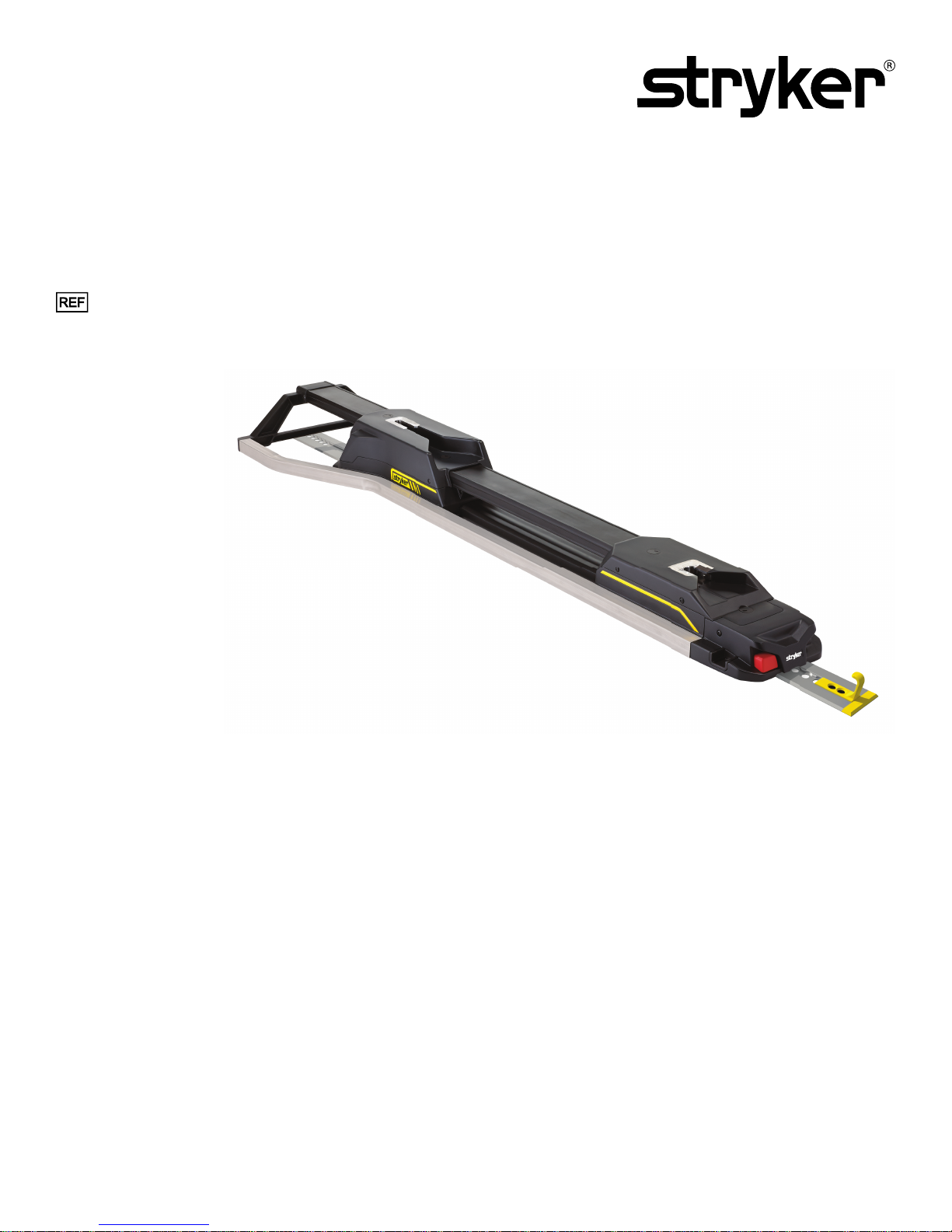
PPeerrffoorrmmaannccee--LLOOAADD™™ CCoott FFaasstteenneerr SSyysstteemm
OOppeerraattiioonnss MMaannuuaall
6392
6392-009-001 Rev D.3
2018/05
EN
Page 2

Page 3
SSyymmbboollss
Refer to instruction manual/booklet
Operating instructions/Consult instructions for use
General warning
Caution
Two person lift
Catalogue number
Serial number
For US Patents see www.stryker.com/patents
European authorized representative
IIPP2266
Manufacturer
Date of manufacture
CE mark
Class II electrical equipment: equipment in which protection against electric shock does not rely
on basic insulation only, but in which additional safety precautions such as double insulation or
reinforced insulation are provided, there being no provision for protective earthing or reliance
upon installation conditions.
Direct current
Medical Equipment Recognized by Underwriters Laboratories LLC With Respect to Electric
Shock, Fire, and Mechanical Hazards only in accordance with ANSI/AAMI ES60601-1: 2005 and
CAN/CSA-C22.2 No. 60601-1:08.
Protection from objects greater than 12.5 mm and powerful water jets
Medical Equipment Classified by Underwriters Laboratories Inc. With Respect to Electric Shock,
Fire, and Mechanical Hazards Only in Accordance with ANSI/AAMI ES60601-1: 2005 and CAN/
CSA-C22.2 No. 60601-1:08.
In accordance with European Directive 2002/96/EC on Waste Electrical and Electronic
Equipment, this symbol indicates that the product must not be disposed of as unsorted municipal
waste, but should be collected separately. Refer to your local distributor for return and/or
collection systems available in your country.
This way up
6392-009-001 Rev D.3 EN
Page 4

Fragile, handle with care
5
Keep dry
Do not stack more than 5 high
EN 6392-009-001 Rev D.3
Page 5

TTaabbllee ooff CCoonntteennttss
Warning/Caution/Note Definition..............................................................................................................................2
Summary of safety precautions ................................................................................................................................3
Introduction ...............................................................................................................................................................5
Product description .................................................................................................................................................5
Indications for use...................................................................................................................................................5
Expected service life ...............................................................................................................................................5
Contraindications ....................................................................................................................................................5
Specifications .........................................................................................................................................................5
Standards with required options ...............................................................................................................................6
Product illustration ..................................................................................................................................................7
Important contact information...................................................................................................................................7
Contact information .................................................................................................................................................8
Serial number location.............................................................................................................................................8
Date of manufacture................................................................................................................................................8
Setup.........................................................................................................................................................................9
Cot compatibility .....................................................................................................................................................9
Installation...............................................................................................................................................................10
Quality system regulation ......................................................................................................................................10
CFR 21 SEC. 820.170 installation ..........................................................................................................................10
CFR 21 SEC. 820.180 general requirements........................................................................................................... 10
Installing the floor plate..........................................................................................................................................11
Performance-LOAD assembly kit checklist.............................................................................................................. 11
Selecting where to install Performance-LOAD ......................................................................................................... 12
Installing Performance-LOAD ................................................................................................................................20
Installation checklist................................................................................................................................................24
Operation ................................................................................................................................................................ 25
Operating guidelines .............................................................................................................................................25
Removing Performance-LOAD quickly....................................................................................................................25
Checking the battery power level............................................................................................................................26
Using a non-upgraded X-frame cot for a mass casualty incident ...............................................................................26
Unloading a compatible cot from Performance-LOAD .............................................................................................. 26
Loading a compatible cot into Performance-LOAD...................................................................................................27
Cleaning and disinfecting with wipes...................................................................................................................... 29
Cleaning..................................................................................................................................................................30
Disinfecting ..........................................................................................................................................................30
Preventive maintenance.........................................................................................................................................31
EMC information..................................................................................................................................................... 32
6392-009-001 Rev D.3 1 EN
Page 6

WWaarrnniinngg//CCaauuttiioonn//NNoottee DDeeffiinniittiioonn
The words WWAARRNNIINNGG, CCAAUUTTIIOONN, and NNOOTTEE carry special meanings and should be carefully reviewed.
WWAARRNNIINNGG -- Alerts the reader about a situation which, if not avoided, could result in death or serious injury. It may also
describe potential serious adverse reactions and safety hazards.
CCAAUUTTIIOONN -- Alerts the reader of a potentially hazardous situation which, if not avoided, may result in minor or moderate
injury to the user or patient or damage to the product or other property. This includes special care necessary for the safe
and effective use of the device and the care necessary to avoid damage to a device that may occur as a result of use or
misuse.
NNoottee -- Provides special information to make maintenance easier or important instructions clearer.
EN 2 6392-009-001 Rev D.3
Page 7

SSuummmmaarryy ooff ssaaffeettyy pprreeccaauuttiioonnss
Always read and strictly follow the warnings and cautions listed on this page. Service only by qualified personnel.
WWAARRNNIINNGG
• PPeerrffoorrmmaannccee--LLOOAADD is designed to be compatible with the PPeerrffoorrmmaannccee--PPRROO XT, PPoowweerr--PPRROO XT, and PPoowweerr--PPRROO
IT cots with a PPeerrffoorrmmaannccee--LLOOAADD option. With the mass casualty option, you can use PPeerrffoorrmmaannccee--LLOOAADD with a
standard antler for most X-frame cots, but a rail clamp assembly and antler is required for all cots without a
PPeerrffoorrmmaannccee--LLOOAADD option.
• It is the responsibility of the cot operator to make sure that the cot being used in the Stryker Model 6392 PPeerrffoorrmmaannccee-LLOOAADD system is a PPeerrffoorrmmaannccee--LLOOAADD compatible cot. Injury may result if a non-compatible cot is used in the Stryker
Model 6392 PPeerrffoorrmmaannccee--LLOOAADD system.
• Always install the cot fastener system as described in this manual. Improper installation can result in injury. Make sure
that, at a minimum, your configuration is tested to meet the National Truck Equipment Association/Ambulance
Manufacturer’s Division Standard 004, Litter Retention System Static Test (AMD-004).
• Take special precautions regarding electromagnetic compatibility (EMC) when you use medical electrical equipment.
Install and place the cot fastener system into service according to the EMC information in this manual. Portable and
mobile RF communications equipment can affect the function of the cot fastener system.
• Always seal all gaps to the exterior of the vehicle to prevent exhaust fumes from entering the vehicle patient
compartment.
• Always make sure that you tighten all four floor plate bolts to the recommended torque.
• Always make sure of PPeerrffoorrmmaannccee--LLOOAADD functionality before use. Failure may result in patient or operator injury.
• Always use caution when you move around in the vehicle patient compartment to avoid tripping on PPeerrffoorrmmaannccee-LLOOAADD.
• Always use caution when you operate PPeerrffoorrmmaannccee--LLOOAADD in adverse weather conditions (for example, rain, ice,
snow).
• Always operate the cot or PPeerrffoorrmmaannccee--LLOOAADD only when all persons are clear of the mechanisms. Entanglement in
powered cot or PPeerrffoorrmmaannccee--LLOOAADD mechanisms can cause serious injury.
• Always practice loading and unloading the cot with PPeerrffoorrmmaannccee--LLOOAADD until operation of the product is fully
understood. Improper use can cause injury.
• Do not allow untrained personnel to assist in the operation of PPeerrffoorrmmaannccee--LLOOAADD. Untrained technicians/personnel
can cause injury to the patient or themselves.
• Always use both hands when you handle the cot. PPeerrffoorrmmaannccee--LLOOAADD is only an assisting device. Evaluate each
situation to determine how to distribute and lift the weight that you are transporting.
• Always use enough operators to handle the forces that are required to load or unload when you handle weights over 400
lb (181 kg). To increase safety, operators should load or unload on flat surfaces. For 36 in. (91 cm) vehicle deck heights,
you may need to manually unload.
• Always avoid extreme parking angles.
• Do not remove the battery when the cot is active.
• Always load or unload an occupied cot into a vehicle with a minimum of two trained operators.
• Always be ready to support the entire weight of the cot and patient when you unload a cot from the vehicle patient
compartment.
• Always check for sheets, restraints, or debris that may catch in the cot transport wheels or load wheels.
• Do not extend the cot base while it is locked into PPeerrffoorrmmaannccee--LLOOAADD.
• Always allow occupants to enter the vehicle patient compartment after the compatible cot has been loaded into the
vehicle patient compartment.
• Always use any appropriate personal protective equipment while power washing to avoid inhaling contagion. Power
washing equipment may aerate contamination.
CCAAUUTTIIOONN
• Improper usage of the product can cause injury to the patient or operator. Operate the product only as described in this
manual.
• Do not modify the product or any components of the product. Modifying the product can cause unpredictable operation
resulting in injury to patient or operator. Modifying the product also voids its warranty.
6392-009-001 Rev D.3 3 EN
Page 8

• The use of accessories and cables, other than those specified, with the exception of cables that are sold by Stryker as
replacement parts for internal components, may result in increased emissions or decreased immunity of the
PPeerrffoorrmmaannccee--LLOOAADD system.
• Do not use the PPeerrffoorrmmaannccee--LLOOAADD system and the PPoowweerr--PPRROO cot adjacent to or stacked with other equipment. If
adjacent or stacked use is necessary, observe the PPeerrffoorrmmaannccee--LLOOAADD system to confirm normal operation in the
configuration where it will be used.
• Do not use portable RF communications equipment (including peripherals such as antenna cables and external
antennas) no closer than 30 cm (12 in.) to any part of the PPeerrffoorrmmaannccee--LLOOAADD system, including cables specified by
the manufacturer. Otherwise, degradation of the performance of this equipment could result.
• The emissions characteristics of this equipment make it suitable for use in industrial areas and hospitals (CISPR 11
class A). This equipment generates, uses, and can radiate radio frequency energy and, if not installed and used in
accordance with the instruction manual, may cause harmful interference to radio communications. Operation of this
equipment in a residential area (for which CISPR 11 class B is normally required) is likely to cause harmful interference
in which case the user will be required to correct the interference at their expense. In the event of interference, please
relocate or reorient the PPeerrffoorrmmaannccee--LLOOAADD system or interfering product.
• Always place the wire inside the floor plate pocket, so the fastener assembly does not pinch the wire when you install the
fastener assembly.
• Always charge the cot battery before you place the product into service. An uncharged or depleted battery may cause
poor product performance.
• Do not push the cot into the vehicle patient compartment until you fully retract the cot base.
• Do not clean, service, or perform maintenance while the product is in use.
• Do not clean, disinfect, service, or perform maintenance while the product is in use.
• Always wipe with clean water and dry each product after disinfecting. Some disinfectants are corrosive in nature and
may cause damage to the product. If you do not rinse and dry the product, you may leave a corrosive residue on the
surface of the product. This corrosive residue could cause premature degradation of critical components. Failure to
follow these disinfecting instructions may void your warranty.
EN 4 6392-009-001 Rev D.3
Page 9

IInnttrroodduuccttiioonn
This manual assists you with the operation or maintenance of your Stryker product. Read this manual before operating or
maintaining this product. Set methods and procedures to educate and train your staff on the safe operation or maintenance
of this product.
CCAAUUTTIIOONN
• Improper usage of the product can cause injury to the patient or operator. Operate the product only as described in this
manual.
• Do not modify the product or any components of the product. Modifying the product can cause unpredictable operation
resulting in injury to patient or operator. Modifying the product also voids its warranty.
NNoottee
• This manual is a permanent part of the product and should remain with the product even if the product is sold.
• Stryker continually seeks advancements in product design and quality. This manual contains the most current product
information available at the time of printing. There may be minor discrepancies between your product and this manual. If
you have any questions, contact Stryker Customer Service or Technical Support at 1-800-327-0770.
PPrroodduucctt ddeessccrriippttiioonn
PPeerrffoorrmmaannccee--LLOOAADD is a manual cot fastener designed to secure compatible ambulance cots into a ground-based
transport vehicle for patient transportation purposes and to allow for the insertion and removal of the compatible ambulance
cots.
When the compatible cot is secured in the transport position, PPeerrffoorrmmaannccee--LLOOAADD can inductively charge compatible
model ambulance cots with an inductive charging option. In the event of loss of charging, PPeerrffoorrmmaannccee--LLOOAADD remains
functional for guiding into, securing within, and removing the cot from the vehicle.
IInnddiiccaattiioonnss ffoorr uussee
PPeerrffoorrmmaannccee--LLOOAADD is intended to guide the loading and unloading of a compatible ambulance cot (wheeled stretcher) to
and from a ground-based transport vehicle and to secure the ambulance cot during transport in a fastened position while
also providing an optional inductive charging platform for charge-compatible ambulance cots.
EExxppeecctteedd sseerrvviiccee lliiffee
The PPeerrffoorrmmaannccee--LLOOAADD cot fastener has a seven year expected service life under normal use conditions and with
appropriate periodic maintenance.
CCoonnttrraaiinnddiiccaattiioonnss
None known.
SSppeecciiffiiccaattiioonnss
Length 70 in. 178 cm
Width 19 in. 48 cm
Height 6 in. 15 cm
Floor plate assembly weight 16.5 lb 7.5 kg
6392-009-001 Rev D.3 5 EN
Page 10

Fastener assembly weight 46 lb 21 kg
130 °F
(54 °C)
-30 °F
(-34 °C)
158 °F
(70 °C)
-40 °F
(-40 °C)
93%0%93%
0%
1060 hPa
620
1060 hPa
620
Minimum operators required for loading/unloading an occupied
2
cot
Minimum operators required for loading/unloading an
1
unoccupied cot
Recommended loading height 22 in. to 36 in. 56 cm to 91 cm
Electrical requirements - inductive charging (optional) 12.8 VDC-15.6 VDC, 15A fuse/breaker, 2 conductor 10
AWG cable
Standards KKK-A-1822F
With inductive charging: IEC 60601-1 Edition 3.0, IEC
60601-1 Edition 3.1, IEC 60601-1-2 Edition 3.0, IEC
60601-1-2 Edition 4.0, IEC 60601-1-12 Edition 1.0,
ANSI/AAMI ES60601-1: 2005/(R)2012, CSA-C22.2 No.
60601-1 (2014)
For standards that require specific options, see
Standards with required options
(page 6).
Stryker reserves the right to change specifications without notice. Patents pending.
The yellow and black color scheme is a proprietary trademark of Stryker Corporation.
EEnnvviirroonnmmeennttaall ccoonnddiittiioonnss
OOppeerraattiioonn SSttoorraaggee aanndd ttrraannssppoorrttaattiioonn
Temperature
Relative humidity
Atmospheric pressure
CCAAUUTTIIOONN
• The use of accessories and cables, other than those specified, with the exception of cables that are sold by Stryker as
replacement parts for internal components, may result in increased emissions or decreased immunity of the
PPeerrffoorrmmaannccee--LLOOAADD system.
• Do not use the PPeerrffoorrmmaannccee--LLOOAADD system and the PPoowweerr--PPRROO cot adjacent to or stacked with other equipment. If
adjacent or stacked use is necessary, observe the PPeerrffoorrmmaannccee--LLOOAADD system to confirm normal operation in the
configuration where it will be used.
• Do not use portable RF communications equipment (including peripherals such as antenna cables and external
antennas) no closer than 30 cm (12 in.) to any part of the PPeerrffoorrmmaannccee--LLOOAADD system, including cables specified by
the manufacturer. Otherwise, degradation of the performance of this equipment could result.
• The emissions characteristics of this equipment make it suitable for use in industrial areas and hospitals (CISPR 11
class A). This equipment generates, uses, and can radiate radio frequency energy and, if not installed and used in
accordance with the instruction manual, may cause harmful interference to radio communications. Operation of this
equipment in a residential area (for which CISPR 11 class B is normally required) is likely to cause harmful interference
in which case the user will be required to correct the interference at their expense. In the event of interference, please
relocate or reorient the PPeerrffoorrmmaannccee--LLOOAADD system or interfering product.
SSttaannddaarrddss wwiitthh rreeqquuiirreedd ooppttiioonnss
To be compliant with the standards, you must use PPeerrffoorrmmaannccee--LLOOAADD with the following compatible cots. See the
Operations Manual for your cot model for more information.
EN 6 6392-009-001 Rev D.3
Page 11
NNoottee -- Compatible cot is loaded into PPeerrffoorrmmaannccee--LLOOAADD in powered mode for crash testing.
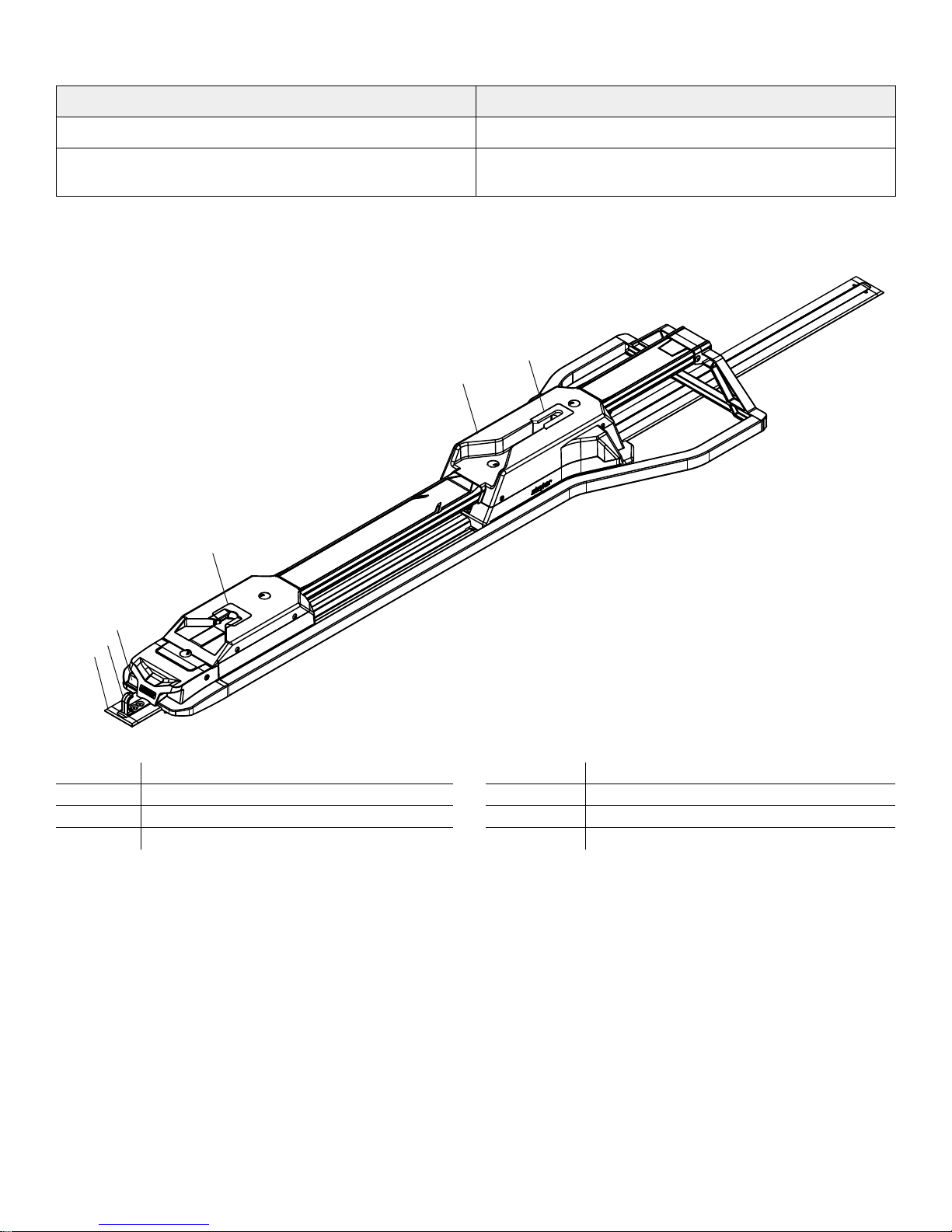
A
B
C
H
D
G
E
F
SSttaannddaarrdd PPeerrffoorrmmaannccee--LLOOAADD ccoommppaattiibbllee ccoott mmooddeellss
SAE J3027 6506, 6086
BS EN 1789:2007 +A2:2014 and AS/NZS-4535:1999
applicable clauses
PPrroodduucctt iilllluussttrraattiioonn
6506
A Foot end E Foot end interface
B
C
D Release button H Head end
Floor plate
Safety hook
IImmppoorrttaanntt ccoonnttaacctt iinnffoorrmmaattiioonn
For information about Federal Ambulance Specification KKK-A-1822F, contact:
Chief, Automotive & Commodity Management Branch (QMDAA)
Office of Motor Vehicle Management
General Services Administration
R2200 Crystal Drive, Suite 1006
Arlington, VA 22202 USA
Telephone: 703-605-2277
6392-009-001 Rev D.3 7 EN
F Cot fastener
G Head end interface
Page 12
For more information about AMD standards, contact:
A
Ambulance Manufacturers Division
(National Truck Equipment Association)
37400 Hills Tech Drive
Farmington Hills, MI 48331-3414 USA
CCoonnttaacctt iinnffoorrmmaattiioonn
Contact Stryker Customer Service or Technical Support at: 1-800-327-0770.
Stryker Medical
3800 E. Centre Avenue
Portage, MI 49002
USA
To view your operations or maintenance manual online, see https://techweb.stryker.com/.
Have the serial number (A) of your Stryker product available when calling Stryker Customer Service or Technical Support.
Include the serial number in all written communication.
SSeerriiaall nnuummbbeerr llooccaattiioonn
DDaattee ooff mmaannuuffaaccttuurree
The year of manufacture is the first four digits of the serial number.
EN 8 6392-009-001 Rev D.3
FFiigguurree 11 –– SSeerriiaall nnuummbbeerr llooccaattiioonn
Page 13

SSeettuupp
During setup, unpack the cartons and check all items for proper operation. Make sure that the product works properly
before you place it in service.
Remove all the shipping and packaging materials from the product before use.
The condition of PPeerrffoorrmmaannccee--LLOOAADD is the responsibility of the user. Have a qualified service person use the following list
and the operation guide instructions to check PPeerrffoorrmmaannccee--LLOOAADD functionality.
1. Confirm that the installation checklist is complete (
2. If the installation checklist was completed by a third-party installer, the end user should repeat the installation checklist.
Do not place PPeerrffoorrmmaannccee--LLOOAADD into service if you cannot complete the installation checklist.
CCoott ccoommppaattiibbiilliittyy
The Stryker Model 6392 PPeerrffoorrmmaannccee--LLOOAADD system is compatible with cots with a PPeerrffoorrmmaannccee--LLOOAADD compatible
option.
WWAARRNNIINNGG
• PPeerrffoorrmmaannccee--LLOOAADD is designed to be compatible with the PPeerrffoorrmmaannccee--PPRROO XT, PPoowweerr--PPRROO XT, and PPoowweerr--PPRROO
IT cots with a PPeerrffoorrmmaannccee--LLOOAADD option. With the mass casualty option, you can use PPeerrffoorrmmaannccee--LLOOAADD with a
standard antler for most X-frame cots, but a rail clamp assembly and antler is required for all cots without a
PPeerrffoorrmmaannccee--LLOOAADD option.
• It is the responsibility of the cot operator to make sure that the cot being used in the Stryker Model 6392 PPeerrffoorrmmaannccee-LLOOAADD system is a PPeerrffoorrmmaannccee--LLOOAADD compatible cot. Injury may result if a non-compatible cot is used in the Stryker
Model 6392 PPeerrffoorrmmaannccee--LLOOAADD system.
Installation checklist
(page 24)).
Cots that currently meet these specifications are:
• Model 6086 PPeerrffoorrmmaannccee--PPRROO XT with a PPeerrffoorrmmaannccee--LLOOAADD option (factory installed) or compatibility kit (6086-700-
007)
• Model 6506 PPoowweerr--PPRROO XT with a PPeerrffoorrmmaannccee--LLOOAADD option (factory installed) or compatibility kit (6506-700-002 or
6506-700-014)
• Model 6516 PPoowweerr--PPRROO IT with a PPeerrffoorrmmaannccee--LLOOAADD option (factory installed) or compatibility kit (6516-700-002)
• Model 6500 PPoowweerr--PPRROO XT with a PPeerrffoorrmmaannccee--LLOOAADD compatibility kit (6500-700-065 or 6500-700-066)
6392-009-001 Rev D.3 9 EN
Page 14

IInnssttaallllaattiioonn
QQuuaalliittyy ssyysstteemm rreegguullaattiioonn
The U.S. Food and Drug Administration (FDA) Code of Federal Regulations (CFR) Title 21 provides guidance regarding the
installation of devices, such as the cot fastener system. To comply with these federal regulations, each device must be
verified to have been properly installed by trained* individuals by following the inspection criteria in the installation checklist.
This document must be maintained for a minimum of seven years for each serial number/installation.
*The installation facility must maintain their own training records showing that the installer was qualified.
CCFFRR 2211 SSEECC.. 882200..117700 iinnssttaallllaattiioonn
(a) Each manufacturer of a device requiring installation shall establish and maintain adequate installation and inspection
instructions, and where appropriate test procedures. Instructions and procedures shall include directions for ensuring
proper installation so that the device will perform as intended after installation. The manufacturer shall distribute the
instructions and procedures with the device or otherwise make them available to the persons installing the device.
(b) The person installing the device shall make sure that the installation, inspection, and any required testing are performed
in accordance with the manufacturer’s instructions and procedures and shall document the inspection and any test results
to demonstrate proper installation.
CCFFRR 2211 SSEECC.. 882200..118800 ggeenneerraall rreeqquuiirreemmeennttss
WWAARRNNIINNGG
• Always install the cot fastener system as described in this manual. Improper installation can result in injury. Make sure
that, at a minimum, your configuration is tested to meet the National Truck Equipment Association/Ambulance
Manufacturer’s Division Standard 004, Litter Retention System Static Test (AMD-004).
• Take special precautions regarding electromagnetic compatibility (EMC) when you use medical electrical equipment.
Install and place the cot fastener system into service according to the EMC information in this manual. Portable and
mobile RF communications equipment can affect the function of the cot fastener system.
All records required by this part shall be maintained at the manufacturing establishment or other location that is reasonably
accessible to responsible officials of the manufacturer and to employees of FDA designated to perform inspections. Such
records, including those not stored at the inspected establishment, shall be made readily available for review and copying
by FDA employee(s). Such records shall be legible and shall be stored to minimize deterioration and to prevent loss. Those
records stored in automated data processing systems shall be backed up.
(a) Confidentiality. Records deemed confidential by the manufacturer may be marked to aid FDA in determining whether
information may be disclosed under the public information regulation in part 20 of this chapter.
(b) Record retention period. All records required by this part shall be retained for a period of time equivalent to the design
and expected life of the device, but in no case less than 2 years from the date of release for commercial distribution by the
manufacturer.
EN 10 6392-009-001 Rev D.3
Page 15

IInnssttaalllliinngg tthhee fflloooorr ppllaattee
0001-194-000 (4)
6392-001-401 (4)
6392-001-400 (2)
6392-001-403 (1)
6392-001-406 (1)
0057-011-000 (1)
6392-001-011 (1)
Install the Stryker universal floor plate in your vehicle patient compartment before you install your cot fastener system. See
the Stryker Global Floor Plate Installation Manual (6390-009-020) for instructions.
PPeerrffoorrmmaannccee--LLOOAADD aasssseemmbbllyy kkiitt cchheecckklliisstt
Make sure that you have all the required components to install the PPeerrffoorrmmaannccee--LLOOAADD system.
PPeerrffoorrmmaannccee--LLOOAADD assembly kit components (6392-001-014)
(2) Cleat (6392-001-400) (4) Cleat locator washer (6392-001-401)
(4) Flat head cap screw (0001-194-000) (1) Center cover assembly (6392-001-011)
• (1) Hex wrench (0057-011-000)
• (1) Floor plate cover (6392-001-403)
• (1) Removal tool extension (6392-001-406)
NNoottee -- Store the hex wrench and removal tool extension (Figure 3) inside of the center cover assembly, so you can access
these tools when you are Removing Performance-LOAD quickly.
6392-009-001 Rev D.3 11 EN
FFiigguurree 22 –– PPeerrffoorrmmaannccee--LLOOAADD aasssseemmbbllyy kkiitt ccoommppoonneennttss
FFiigguurree 33 –– HHeexx wwrreenncchh aanndd rreemmoovvaall ttooooll eexxtteennssiioonn
Page 16

SSeelleeccttiinngg wwhheerree ttoo iinnssttaallll PPeerrffoorrmmaannccee--LLOOAADD
A
Follow these steps to determine location and orientation of cleats and washer locations:
1. Select your sill to cot distance (A) (Figure 4).
Record your distance here: _____
2. Using the table below, select your Section based on your sill to cot distance (A).
Record your section here: _____
3. Proceed to your section to install your cleats.
SSiillll ttoo ccoott ddiissttaannccee ((AA)) SSeeccttiioonn
5 in. (13 cm) Section A
6 in. (15 cm) Section B
7 in. (18 cm) Section C
8 in. (20 cm) Section D
9 in. (23 cm) Section E
10 in. (25 cm) Section F
11 in. (28 cm) Section G
12 in. (30 cm) Section H
FFiigguurree 44 –– SSiillll ttoo ccoott ddiissttaannccee ((AA))
13 in. (33 cm) Section I
14 in. (36 cm) Section J
15 in. (38 cm) Section K
16 in. (41 cm) Section L
17 in. (43 cm) Section M
18 in. (46 cm) Section N
19 in. (48 cm) Section O
20 in. (51 cm) Section P
21 in. (53 cm) Section Q
EN 12 6392-009-001 Rev D.3
Page 17

You can only insert cleats where indicated by . Use the necked area of the cleats to line up with the floor plate, so they
(A)
(B)
8” (20.3 cm)
47” (119.4 cm)
48” (121.9 cm)
9” (22.9 cm)
drop in. Both cleats are identical and must be installed flat-side down. Both cleat dimensions are taken from the cap at the
end of the floor plate.
1. Insert your first cleat (A) and slide toward the foot end.
2. Insert your second cleat (B).
Foot
end
Head
end
3. Determine your cleat (6392-001-400) and cleat locator washer (6392-001-401) locations per your Section below.
4. Using a 5/32” hex wrench, install four flat head cap screws (0001-194-000) and four cleat locator washers to secure the
cleats. Make sure that you install two cleat locator washers per cleat.
5. Proceed to Installing Performance-LOAD.
SSeeccttiioonn AA:: 5 in. (13 cm) sill to cot distance
SSeeccttiioonn BB:: 6 in. (15 cm) sill to cot distance
6392-009-001 Rev D.3 13 EN
Page 18

SSeeccttiioonn CC:: 7 in. (18 cm) sill to cot distance
49” (124.5 cm)
10” (25.4 cm)
(A)
(B)
50” (127.0 cm)
11” (27.9 cm)
You can only insert cleats where indicated by . Use the necked area of the cleats to line up with the floor plate, so they
drop in. Both cleats are identical and must be installed flat-side down. Both cleat dimensions are taken from the cap at the
end of the floor plate.
1. Insert your first cleat (A) and slide toward the foot end.
2. Insert your second cleat (B).
Foot
end
Head
end
3. Determine your cleat (6392-001-400) and cleat locator washer (6392-001-401) locations per your Section below.
4. Using a 5/32” hex wrench, install four flat head cap screws (0001-194-000) and four cleat locator washers to secure the
cleats. Make sure that you install two cleat locator washers per cleat.
5. Proceed to Installing Performance-LOAD.
SSeeccttiioonn DD:: 8 in. (20 cm) sill to cot distance
EN 14 6392-009-001 Rev D.3
Page 19

SSeeccttiioonn EE:: 9 in. (23 cm) sill to cot distance
51” (129.5 cm)
12” (30.5 cm)
6392-009-001 Rev D.3 15 EN
Page 20

You can only insert cleats where indicated by . Use the necked area of the cleats to line up with the floor plate, so they
(A)
(B)
6.5”(16.5 cm)
52” (132.1 cm)
53” (134.6 cm)
7.5”(19.1 cm)
drop in. Both cleats are identical and must be installed flat-side down. Both cleat dimensions are taken from the cap at the
end of the floor plate.
1. Insert your first cleat (A) and slide toward the foot end.
2. Insert your second cleat (B).
Foot
end
Head
end
3. Determine your cleat (6392-001-400) and cleat locator washer (6392-001-401) locations per your Section below.
4. Using a 5/32” hex wrench, install four flat head cap screws (0001-194-000) and four cleat locator washers to secure the
cleats. Make sure that you install two cleat locator washers per cleat.
5. Proceed to Installing Performance-LOAD.
SSeeccttiioonn FF:: 10 in. (25 cm) sill to cot distance
SSeeccttiioonn GG:: 11 in. (28 cm) sill to cot distance
EN 16 6392-009-001 Rev D.3
Page 21

SSeeccttiioonn HH:: 12 in. (30 cm) sill to cot distance
54” (137.2 cm)
8.5”(21.6 cm)
(A)
(B)
55” (139.7 cm)
9.5”(24.1 cm)
You can only insert cleats where indicated by . Use the necked area of the cleats to line up with the floor plate, so they
drop in. Both cleats are identical and must be installed flat-side down. Both cleat dimensions are taken from the cap at the
end of the floor plate.
1. Insert your first cleat (A) and slide toward the foot end.
2. Insert your second cleat (B).
Foot
end
Head
end
3. Determine your cleat (6392-001-400) and cleat locator washer (6392-001-401) locations per your Section below.
4. Using a 5/32” hex wrench, install four flat head cap screws (0001-194-000) and four cleat locator washers to secure the
cleats. Make sure that you install two cleat locator washers per cleat.
5. Proceed to Installing Performance-LOAD.
SSeeccttiioonn II:: 13 in. (33 cm) sill to cot distance
6392-009-001 Rev D.3 17 EN
Page 22

SSeeccttiioonn JJ:: 14 in. (36 cm) sill to cot distance
56” (142.2 cm)
10.5”(26.7 cm)
57” (144.8 cm)
11.5”(29.2 cm)
(A)
(B)
SSeeccttiioonn KK:: 15 in. (38 cm) sill to cot distance
You can only insert cleats where indicated by . Use the necked area of the cleats to line up with the floor plate, so they
drop in. Both cleats are identical and must be installed flat-side down. Both cleat dimensions are taken from the cap at the
end of the floor plate.
1. Insert your first cleat (A) and slide toward the foot end.
2. Insert your second cleat (B).
Foot
end
Head
end
3. Determine your cleat (6392-001-400) and cleat locator washer (6392-001-401) locations per your Section below.
4. Using a 5/32” hex wrench, install four flat head cap screws (0001-194-000) and four cleat locator washers to secure the
cleats. Make sure that you install two cleat locator washers per cleat.
5. Proceed to Installing Performance-LOAD.
EN 18 6392-009-001 Rev D.3
Page 23

SSeeccttiioonn LL:: 16 in. (41 cm) sill to cot distance
58” (147.3 cm)
12.5”(31.8 cm)
59” (149.9 cm)
13.5”(34.3 cm)
60” (152.4 cm)
14.5”(36.8 cm)
(A)
(B)
SSeeccttiioonn MM:: 17 in. (43 cm) sill to cot distance
SSeeccttiioonn NN:: 18 in. (46 cm) sill to cot distance
You can only insert cleats where indicated by . Use the necked area of the cleats to line up with the floor plate, so they
drop in. Both cleats are identical and must be installed flat-side down. Both cleat dimensions are taken from the cap at the
end of the floor plate.
1. Insert your first cleat (A) and slide toward the foot end.
2. Insert your second cleat (B).
Foot
end
Head
end
3. Determine your cleat (6392-001-400) and cleat locator washer (6392-001-401) locations per your Section below.
6392-009-001 Rev D.3 19 EN
Page 24

4. Using a 5/32” hex wrench, install four flat head cap screws (0001-194-000) and four cleat locator washers to secure the
61” (154.9 cm)
22”(55.9 cm)
62” (157.5 cm)
23”(58.4 cm)
63” (160.0 cm)
24”(61.0 cm)
cleats. Make sure that you install two cleat locator washers per cleat.
5. Proceed to Installing Performance-LOAD.
SSeeccttiioonn OO:: 19 in. (48 cm) sill to cot distance
SSeeccttiioonn PP:: 20 in. (51 cm) sill to cot distance
SSeeccttiioonn QQ:: 21 in. (53 cm) sill to cot distance
IInnssttaalllliinngg PPeerrffoorrmmaannccee--LLOOAADD
TToooollss rreeqquuiirreedd::
Hack saw Rubber hammer
Slotted screwdriver 3/8” hex wrench (at least 5-3/8 in. (13.7 cm) length)
3/8” drive torque wrench (ft-lb) > 60 ft-lb Silicone sealant
PPrroocceedduurree::
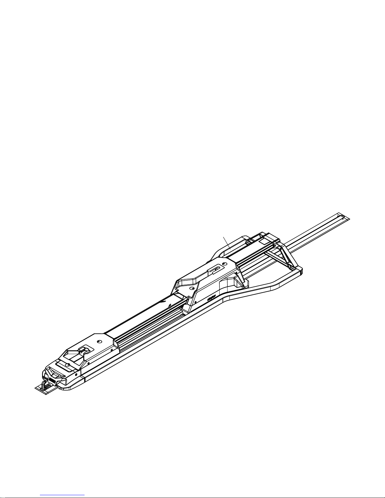
1. Carefully place PPeerrffoorrmmaannccee--LLOOAADD on top of the floor plate assembly. Align the two bolts at the head end with the two
holes in the cleat as shown in Figure 5.
EN 20 6392-009-001 Rev D.3
Page 25

FFiigguurree 55 –– PPeerrffoorrmmaannccee--LLOOAADD aalliiggnnmmeenntt
2. If you are not planning to install the floor plate caps, skip to step 6.
3. To install the floor plate caps, measure the exposed pocket at the head end and the foot end of the floor plate to
customize the floor plate cap, which is included with the floor plate assembly kit (6390-009-020). See
plate
(page 11).
Installing the floor
NNoottee -- It is recommended that you add an additional 1 in. (2.5 cm) to the floor plate cap at the foot end to allow for
overlap with PPeerrffoorrmmaannccee--LLOOAADD.
4. Using a hack saw, cut two pieces of the floor plate cap to fit the measured length on both ends. The floor plate cap does
not fit over the cleat. To cover a cleat, cut or remove the vertical tabs where they may interfere with the cleat (Figure 6).
FFiigguurree 66 –– CCuutt fflloooorr ppllaattee ccaappss
5. Using a rubber hammer, snap each floor plate cap into the floor plate (hook side first).
NNoottee -- To unsnap the floor plate cap, use a slotted screwdriver on the side of the cover with a raised edge.
6. If your system is not equipped with inductive charging, skip to step 12.
7. If your system is equipped with inductive charging, follow steps 8-11.
8. Lay the excess wire into the floor plate pocket. Align the four holes with the mounting holes in the cleats.
CCAAUUTTIIOONN -- Always place the wire inside the floor plate pocket, so the fastener assembly does not pinch the wire when
you install the fastener assembly.
9. Connect the red and black wires from the fastener assembly to the anchor-to-vehicle cable (6390-001-135). Connect the
red wire from the fastener assembly to the red wire on the anchor-to-vehicle cable. Connect the black wire from the
fastener assembly to the black wire on the anchor-to-vehicle cable. Feed any excess wire through the electrical rubber
grommet.
6392-009-001 Rev D.3 21 EN
Page 26

NNoottee -- If you have a previously installed floor plate without the anchor-to-vehicle cable, measure either 3 in. or 7 in.
C
B
A
AA
B
toward the head end from the locator position A (Figure 7). Mark the location in the middle of the channel. This will be
your electrical inlet location. See Installing the floor plate (6390-009-020) for instructions about how to connect the
electrical.
FFiigguurree 77 –– FFlloooorr ppllaattee llooccaattoorr ppoossiittiioonn -- ffoooott eenndd
NNoottee -- The safety hook (B) and extra mounting hole locations (C) are shown for reference only (Figure 7). They are not
used for PPeerrffoorrmmaannccee--LLOOAADD installation.
10.Place the connectors into the floor plate pocket.
11.Apply silicone sealant to the electrical rubber grommet to completely seal the electrical pass through.
WWAARRNNIINNGG -- Always seal all gaps to the exterior of the vehicle to prevent exhaust fumes from entering the vehicle
patient compartment.
12.Rotate the spin caps (A) a half turn to access the attached floor plate bolts that are under the caps (Figure 8).
NNoottee -- Do not fully tighten the floor plate bolts until all four bolts are aligned and started.
13.Using a 3/8” hex wrench, install the attached floor plate bolt that is closest to the head end.
14.Using a 3/8” hex wrench, install the other three attached floor plate bolts (A) into the two cleats (Figure 8).
15.Using a torque wrench, tighten each floor plate bolt to 60±10 ft-lb.
WWAARRNNIINNGG -- Always make sure that you tighten all four floor plate bolts to the recommended torque.
16.Close the spin caps.
17.Insert the un-notched side of the center cover assembly (6392-001-011) (B) into the opening in the head end housing
(Figure 8).
EN 22 6392-009-001 Rev D.3
FFiigguurree 88 –– AAttttaacchh tthhee ffaasstteenneerr
Page 27

18.Drop the center cover assembly down to align with the floor plate.
19.Slide the center cover assembly into the opening in the foot end housing.
20.Continue to slide the center cover assembly toward the foot end until the post comes through the notch.
21.Complete the
Installation checklist
(page 24).
6392-009-001 Rev D.3 23 EN
Page 28

IInnssttaallllaattiioonn cchheecckklliisstt
Follow this checklist with a PPeerrffoorrmmaannccee--LLOOAADD compatible PPoowweerr--PPRROO cot (model 6500, 6506, 6516) or PPeerrffoorrmmaannccee-PPRROO cot (Model 6086).
Make sure that you do not have any unused components after installation. Your PPeerrffoorrmmaannccee--LLOOAADD system does
not ship with any extra components. If you have any unused components after installation, call Stryker service.
Using a torque wrench, double check that all four attached floor plate bolts (A) are tightened 60+/-10 ft-lb. (Figure 8).
Visually check that all bolts and screws are properly tightened with no signs of protruding or missing fasteners.
Lift the vehicle bumper to the raised position, if equipped.
Load the PPeerrffoorrmmaannccee--LLOOAADD compatible cot into PPeerrffoorrmmaannccee--LLOOAADD.
Check that the head end pin slides freely into the head end interface. If not, call Stryker service.
Make sure that the cot is locked into PPeerrffoorrmmaannccee--LLOOAADD by firmly pulling in and out and side to side on the foot end
of the cot.
Press the release button at the foot end of PPeerrffoorrmmaannccee--LLOOAADD and push toward the head end to unlock the
fastener. Pull to remove the cot from the vehicle patient compartment. Make sure that the cot is released.
For Type II ambulances or if the cot center line is 17-1/2 in. or less from the vehicle wall, make sure that the optional
wheel guide assembly (6390-027-000) is installed. Mark N/A if the wheel guide is not required.
If equipped with inductive charging, install a depleted cot battery into a PPeerrffoorrmmaannccee--LLOOAADD compatible PPoowweerr--
PPRROO cot, load the cot into PPeerrffoorrmmaannccee--LLOOAADD. Make sure that the cot battery LED indicator is flashing green to
indicate that it is charging.
Product serial number:
Installed by: Date:
Inspected by: Date:
NNoottee -- Maintain a copy of this record for at least seven years.
EN 24 6392-009-001 Rev D.3
Page 29

OOppeerraattiioonn
OOppeerraattiinngg gguuiiddeelliinneess
WWAARRNNIINNGG
• Always make sure of PPeerrffoorrmmaannccee--LLOOAADD functionality before use. Failure may result in patient or operator injury.
• Always use caution when you move around in the vehicle patient compartment to avoid tripping on PPeerrffoorrmmaannccee-LLOOAADD.
• Always use caution when you operate PPeerrffoorrmmaannccee--LLOOAADD in adverse weather conditions (for example, rain, ice,
snow).
• Always operate the cot or PPeerrffoorrmmaannccee--LLOOAADD only when all persons are clear of the mechanisms. Entanglement in
powered cot or PPeerrffoorrmmaannccee--LLOOAADD mechanisms can cause serious injury.
• Always practice loading and unloading the cot with PPeerrffoorrmmaannccee--LLOOAADD until operation of the product is fully
understood. Improper use can cause injury.
• Do not allow untrained personnel to assist in the operation of PPeerrffoorrmmaannccee--LLOOAADD. Untrained technicians/personnel
can cause injury to the patient or themselves.
• Always use both hands when you handle the cot. PPeerrffoorrmmaannccee--LLOOAADD is only an assisting device. Evaluate each
situation to determine how to distribute and lift the weight that you are transporting.
• Always use enough operators to handle the forces that are required to load or unload when you handle weights over 400
lb (181 kg). To increase safety, operators should load or unload on flat surfaces. For 36 in. (91 cm) vehicle deck heights,
you may need to manually unload.
• Always avoid extreme parking angles.
• Check PPeerrffoorrmmaannccee--LLOOAADD for proper functionality before you start each shift.
• Operate PPeerrffoorrmmaannccee--LLOOAADD with the vehicle on a flat surface, if possible.
• If you are unable to unload an occupied cot from the vehicle patient compartment, use a backboard to unload the
patient.
RReemmoovviinngg PPeerrffoorrmmaannccee--LLOOAADD qquuiicckkllyy
You can use the supplied tools to quickly remove PPeerrffoorrmmaannccee--LLOOAADD from your vehicle patient compartment, if
necessary.
To quickly remove PPeerrffoorrmmaannccee--LLOOAADD:
1. Remove the center cover assembly (6390-001-011) from the head end housing.
2. Remove the hex wrench and removal tool extension from the center cover assembly (Figure 9).
FFiigguurree 99 –– HHeexx wwrreenncchh aanndd rreemmoovvaall ttooooll eexxtteennssiioonn
3. Rotate the spin caps a half turn to access the attached floor plate bolts that are under the caps
6392-009-001 Rev D.3 25 EN
Page 30

4. Insert the small end of the hex wrench (0057-011-000) into the removal tool extension (6392-001-406) to loosen the four
bolts.
NNoottee -- You cannot remove the four floor plate bolts as they are self contained within PPeerrffoorrmmaannccee--LLOOAADD.
5. Carefully remove the fastener assembly from the floor plate assembly.
6. If equipped with inductive charging, disconnect the red wire from the red wire and the black wire from the black wire to
disconnect the fastener assembly from the anchor-to-vehicle cable.
To reinstall, see Installing Performance-LOAD.
CChheecckkiinngg tthhee bbaatttteerryy ppoowweerr lleevveell
Use the cot battery LED indictor to check the SSMMRRTT Pak power level. A charged SSMMRRTT Pak, in working condition, provides
up to 2 calls with a 250 pound patient (actual results may vary). The 24 VDC PPoowweerr--PPRROO system and the SSMMRRTT Pak is
rated for 2.4 amp-hours of electric energy.
WWAARRNNIINNGG -- Do not remove the battery when the cot is active.
CCAAUUTTIIOONN -- Always charge the cot battery before you place the product into service. An uncharged or depleted battery may
cause poor product performance.
To check the battery power level, press the retract (-) button on the cot control switch to activate the cot battery LED
indicator. The cot battery LED indicator is located at the foot end control enclosure (shown as a battery symbol).
• The LED is solid green when the battery has a full charge or has an adequate battery power charge.
NNoottee -- For best results, use the SSMMRRTT Pak until the cot battery LED indicator changes from solid green to flashing
amber.
• The LED flashes amber when you need to charge or replace the battery
NNoottee -- The cot battery LED indicator does not have to flash amber before you remove and replace the SSMMRRTT Pak,
however, this is considered to be a best practice. You can remove and recharge the SSMMRRTT Pak at any time.
• The LED is a solid amber to indicate a battery error.
NNoottee
• Only use Stryker approved batteries.
• If equipped with inductive charging, the powered cot fastener automatically charges the SSMMRRTT Pak battery. Automatic
charging occurs when you lock the cot into the powered cot fastener (no cable or connectors required). The cot battery
LED indicator flashes green for a moment to signify that it is charging.
• Automatic charging will only occur with SSMMRRTT Pak batteries.
UUssiinngg aa nnoonn--uuppggrraaddeedd XX--ffrraammee ccoott ffoorr aa mmaassss ccaassuuaallttyy iinncciiddeenntt
You can use some non-compatible cots, including most X-frame cots, in a a mass casualty incident when equipped with the
mass casualty option for PPeerrffoorrmmaannccee--LLOOAADD and a manual Stryker cot fastener.
The loading and unloading operations are the same as the instructions for manual loading and unloading of a cot.
UUnnllooaaddiinngg aa ccoommppaattiibbllee ccoott ffrroomm PPeerrffoorrmmaannccee--LLOOAADD
WWAARRNNIINNGG
• Always load or unload an occupied cot into a vehicle with a minimum of two trained operators.
• Always be ready to support the entire weight of the cot and patient when you unload a cot from the vehicle patient
compartment.
• Always check for sheets, restraints, or debris that may catch in the cot transport wheels or load wheels.
EN 26 6392-009-001 Rev D.3
Page 31

• Do not extend the cot base while it is locked into PPeerrffoorrmmaannccee--LLOOAADD.
1. Press and hold the release button at the foot end of the PPeerrffoorrmmaannccee--LLOOAADD system and push the cot toward the head
end of the vehicle patient compartment to relieve the load on the latch.
2. Grasp the cot frame at the foot end to pull the cot out of the vehicle patient compartment.
For model 6500 , model 6506 and model 6516 with PPeerrffoorrmmaannccee--LLOOAADD:
• Operator 1: Grasp the cot frame at the foot end. While you support the weight of the cot, guide and pull the cot out
of the vehicle patient compartment until the safety hook catches. Press and hold the extend (+) button on the cot
control switch to extend the cot until the cot wheels rest on the ground.
• Operator 2: Grasp the outer rail to stabilize the cot. Unlatch the safety hook when the base is fully extended.
For model 6086 with the PPeerrffoorrmmaannccee--LLOOAADD:
• Operator 1: Grasp the cot frame. While you support the weight of the cot, guide and pull the cot out of the vehicle
patient compartment until the safety hook catches.
• Operator 2: Grasp the base frame where indicated, lift slightly, and lower the base frame to its fully extended
position while Operator 1 squeezes and holds the cot manual release. Make sure that the cot wheels are on the
ground.
• Operator 1 (foot end): Release the cot manual release to lock the undercarriage into the extended position.
• Operator 2: Unlatch the safety hook when the base is fully extended.
LLooaaddiinngg aa ccoommppaattiibbllee ccoott iinnttoo PPeerrffoorrmmaannccee--LLOOAADD
WWAARRNNIINNGG
• Always load or unload an occupied cot into a vehicle with a minimum of two trained operators.
• Always allow occupants to enter the vehicle patient compartment after the compatible cot has been loaded into the
vehicle patient compartment.
• Always check for sheets, restraints, or debris that may catch in the cot transport or load wheels.
CCAAUUTTIIOONN -- Do not push the cot into the vehicle patient compartment until you fully retract the cot base.
1. Lift the vehicle bumper to the raised position, if equipped.
2. Fully extend and lock the cot retractable head section before you load the cot into the powered cot fastener.
3. Place the cot in a loading position (any position where the loading wheels meet the vehicle patient compartment floor
height).
4. Roll the cot to the open vehicle patient compartment.
5. Push the cot forward until the loading wheels are on the vehicle patient compartment floor and the safety bar passes the
safety hook.
NNoottee -- For maximum clearance to lift the base, pull the cot out until the safety bar is connected to the safety hook.
For model 6500, model 6506, model 6516 with PPeerrffoorrmmaannccee--LLOOAADD:
• Grasp the cot frame at the foot end.
• Lift the foot end of the cot and press and hold the retract (-) button on the cot control switch to fully retract the cot
undercarriage.
NNoottee -- The cot undercarriage will retract in less than three seconds.
6392-009-001 Rev D.3 27 EN
Page 32

For model 6086 with PPeerrffoorrmmaannccee--LLOOAADD:
• Operator 1 (foot end): Grasp the cot frame at the foot end. Squeeze and hold the cot manual release.
• Operator 2 (side): Grasp the outer rail to stabilize the cot. Then, grasp the base frame. After the foot end operator
has lifted the cot and squeezed the cot manual release, retract the undercarriage with one hand and hold it in
place.
• Operator 1 (foot end): Release the cot manual release to lock the undercarriage in the retracted position.
6. Push the cot into the vehicle patient compartment until the cot locks into the cot fastener.
7. Make sure that the cot is locked into the cot fastener by firmly pulling in and out and side to side on the foot end of the
cot.
EN 28 6392-009-001 Rev D.3
Page 33

CClleeaanniinngg aanndd ddiissiinnffeeccttiinngg wwiitthh wwiippeess
For United States only. Confirm availability for your configuration or region. Call Stryker Customer Service: 1-800-327-
0770.
Stryker’s preferred wipes (2060-000-001 6'' x 10'' or 2060-000-002 9'' x 12'') include the following active ingredients:
• n-Alkyl (60% C14, 30% C16, 5% C12, 5% C18) dimethyl benzyl ammonium chloride - 0.154%
• n-Alkyl (68% C12, 32% C14) dimethyl ethylbenzyl ammonium chloride - 0.154%
• Isopropanol - 21.000%
Non-active ingredient: Ethylene Glycol Monobutyl Ether – < 3%
NNoottee -- For safety information, read the product label.
To clean or disinfect the external product surface:
1. To clean, wipe external surfaces with a fresh, clean wipe to remove all visible soils. Repeat as necessary until the
product is clean.
NNoottee
• Use as many wipes as necessary.
• Complete step 1 before you disinfect.
2. To disinfect, wipe external surfaces with a fresh, clean wipe until wet. Allow the external surface to remain wet for two
minutes at room temperature.
3. Allow the product to dry before you return it to service.
6392-009-001 Rev D.3 29 EN
Page 34

CClleeaanniinngg
WWAARRNNIINNGG -- Always use any appropriate personal protective equipment while power washing to avoid inhaling contagion.
Power washing equipment may aerate contamination.
CCAAUUTTIIOONN -- Do not clean, service, or perform maintenance while the product is in use.
The product is power washable. The product may show some signs of oxidation or discoloration from continuous washing.
No degradation of the product’s performance will occur from power washing as long as you follow the proper procedures.
• Follow the cleaning solution manufacturer’s dilution recommendations exactly.
• Power wash with recommended cleaners. Hose down the product and towel dry the guide.
• Power wash the rails and interface plates with a hand held wand unit or wipe the product with a clean cloth and
recommended cleaners.
NNoottee -- Water that gets into the PPeerrffoorrmmaannccee--LLOOAADD system will drain through the drain tube to the underside of the
vehicle.
DDiissiinnffeeccttiinngg
CCAAUUTTIIOONN
• Do not clean, disinfect, service, or perform maintenance while the product is in use.
• Always wipe with clean water and dry each product after disinfecting. Some disinfectants are corrosive in nature and
may cause damage to the product. If you do not rinse and dry the product, you may leave a corrosive residue on the
surface of the product. This corrosive residue could cause premature degradation of critical components. Failure to
follow these disinfecting instructions may void your warranty.
In general, when used in concentrations recommended by the manufacturer, you can use either phenolic or quaternary
(excluding VViirreexx® TB) type disinfectants. Iodophor type disinfectants are not recommended for use because staining may
occur.
The recommended disinfectants for this product’s surfaces include the following:
• Quaternary (active ingredient - ammonium chloride) that contain less than 3% glycol ether
• Phenolic (active ingredient - o-phenylphenol)
• Chlorinated bleach solution (use up to UK disinfecting 10,000 ppm available chlorine (941 mL of a 5.25% sodium
hypochlorite solution per 4000 mL of water)
• Alcohol (active ingredient - 70% isopropyl alcohol)
To wipe down the product with disinfectant between uses:
1. Follow the manufacturer’s dilution recommendations exactly.
2. Apply the recommended disinfectant solution by spray or pre-soaked wipes.
3. Hand wash all surfaces of the product with the recommended disinfectant.
4. Disinfect all exposed surfaces. Pay attention to high contact areas.
5. Follow the disinfecting solution manufacturer’s instructions for appropriate contact time and rinsing requirements.
6. Dry the product thoroughly before returning the product to service.
Avoid over saturation. Do not allow the product to remain wet.
Follow the manufacturer’s dilution recommendations for appropriate contact time and rinsing requirements. Follow the
chemical manufacturer’s guidelines for proper disinfecting.
EN 30 6392-009-001 Rev D.3
Page 35

PPrreevveennttiivvee mmaaiinntteennaannccee
Establish and follow a maintenance schedule and keep records of the maintenance activity. Remove product from service
before you perform the preventive maintenance inspection. You may need to perform preventive maintenance checks more
often based on your level of product usage. Service only by qualified personnel.
EEvveerryy mmoonntthh
CChheecckk RRoouuttiinnee
Foot end interface and head end interface Clean debris
EEvveerryy tthhrreeee mmoonntthhss
CChheecckk RRoouuttiinnee
Loose fasteners Replace if loose
EEvveerryy ttwweellvvee mmoonntthhss
CChheecckk RRoouuttiinnee
All parts Replace any worn parts, including covers, cot guides, and
latch assembly, if necessary
Full functionality See
Installation checklist
(page 24)
6392-009-001 Rev D.3 31 EN
Page 36

EEMMCC iinnffoorrmmaattiioonn
GGuuiiddaannccee aanndd mmaannuuffaaccttuurreerr’’ss ddeeccllaarraattiioonn -- eelleeccttrroommaaggnneettiicc eemmiissssiioonnss
PPeerrffoorrmmaannccee--LLOOAADD is intended for use in the electromagnetic environment specified below. The customer or the user
of PPeerrffoorrmmaannccee--LLOOAADD should assure that it is used in such an environment.
EEmmiissssiioonnss tteesstt
RF Emissions
CISPR 11
RF Emissions
CISPR 11
RReeccoommmmeennddeedd sseeppaarraattiioonnss ddiissttaanncceess bbeettwweeeenn ppoorrttaabbllee aanndd mmoobbiillee RRFF ccoommmmuunniiccaattiioonnss eeqquuiippmmeenntt aanndd
PPeerrffoorrmmaannccee--LLOOAADD is intended for use in an electromagnetic environment in which radiated RF disturbances are
controlled. The customer or the user of PPeerrffoorrmmaannccee--LLOOAADD can help prevent electromagnetic interferences by
maintaining a minimum distance between portable and mobile RF communications equipment (transmitters) and
PPeerrffoorrmmaannccee--LLOOAADD as recommended below, according to the maximum output power of the communications
equipment.
RRaatteedd mmaaxxiimmuumm oouuttppuutt
ppoowweerr ooff ttrraannssmmiitttteerr
CCoommpplliiaannccee EElleeccttrroommaaggnneettiicc eennvviirroonnmmeenntt
The PPeerrffoorrmmaannccee--LLOOAADD system must emit
Group 2
Class A
PPeerrffoorrmmaannccee--LLOOAADD
SSeeppaarraattiioonn ddiissttaannccee aaccccoorrddiinngg ttoo ffrreeqquueennccyy ooff ttrraannssmmiitttteerr
electromagnetic energy in order to perform its
intended function. Nearby electronic
equipment may be affected.
The PPeerrffoorrmmaannccee--LLOOAADD system is suitable
for use in all establishments other than
domestic and those directly connected to the
public low-voltage power supply network that
supplies buildings used for domestic
purposes.
mm
WW
0.01 0.12 0.035 0.07
0.1 0.38 0.11 0.22
1 1.2 0.35 0.7
10 3.8 1.1 2.2
100 12 3.5 7
For transmitters rated at a maximum output power not listed above, the recommended separation distance d in meters
(m) can be estimated using the equation applicable to the frequency of the transmitter, where P is the maximum output
power rating of the transmitter in watts (W) according to the transmitter manufacturer. Note 1: At 80 MHz and 800 MHz,
the separation distance for the higher frequency range applies. Note 2: These guidelines may not apply in all situations.
Electromagnetic propagation is affected by absorption and reflection from structures, objects, and people.
GGuuiiddaannccee aanndd mmaannuuffaaccttuurreerr’’ss ddeeccllaarraattiioonn -- eelleeccttrroommaaggnneettiicc iimmmmuunniittyy
PPeerrffoorrmmaannccee--LLOOAADD is suitable for use in the electromagnetic environment specified below. The customer or the user of
PPeerrffoorrmmaannccee--LLOOAADD should assure that it is used in such an environment.
IImmmmuunniittyy tteesstt
115500 kkHHzz ttoo 8800 MMHHzz
dd==((11..22)) ((√√PP))
EENN//IIEECC 6600660011 tteesstt lleevveell
8800 MMHHzz ttoo 880000 MMHHzz
dd==((..1188)) ((√√PP))
CCoommpplliiaannccee lleevveell
880000 MMHHzz ttoo 22..55 GGHHzz
dd==((..3355)) ((√√PP))
EElleeccttrroommaaggnneettiicc
eennvviirroonnmmeenntt--gguuiiddaannccee
EN 32 6392-009-001 Rev D.3
Page 37

GGuuiiddaannccee aanndd mmaannuuffaaccttuurreerr’’ss ddeeccllaarraattiioonn -- eelleeccttrroommaaggnneettiicc iimmmmuunniittyy
Electrostatic discharge
(ESD)
IEC 61000-4-2
Power frequency (50/60 Hz)
magnetic field
IEC 61000-4-8
+8 kV contact
+15 kV air
+8 kV contact
+15 kV air
30 A/m 30 A/m
Floors should be wood,
concrete, or ceramic tile. If
floors are covered with
synthetic material, the
relative humidity should be
at least 30%.
Power frequency magnetic
fields should be at levels
characteristic of a typical
location in a typical
commercial or hospital
environment.
NNoottee:: U
is the a.c. mains voltage before applications of the test level.
T
Conducted RF
IEC 61000-4-6
Radiated RF
IEC 61000-4-3
3 Vrms
150 kHz to 80 MHz
10 V/m
80 MHz to 2.5 GHz
3 Vrms
10 V/m
Portable and mobile RF
communications equipment
should be used no closer to
any part of PPeerrffoorrmmaannccee-LLOOAADD, including cables,
than the recommended
separation distance
calculated from the equation
appropriate for the
frequency of the transmitter.
Recommended separation
distance
P
D=(.35) (√
)
80 MHz to 800 MHz
D=(0.70) (√
P
)
800 MHz to 2.5 GHz
where
P
is the maximum
output power rating of the
transmitter in watts (W)
according to the transmitter
manufacturer and
d
is the
recommended separation
distance in meters (m).
6392-009-001 Rev D.3 33 EN
Field strengths from fixed
RF transmitters, as
determined by an
electromagnetic site
a
should be less than the
compliance level in each
frequency range.
b
Interference may occur in
the vicinity of equipment
marked with the following
symbol:
Page 38

GGuuiiddaannccee aanndd mmaannuuffaaccttuurreerr’’ss ddeeccllaarraattiioonn -- eelleeccttrroommaaggnneettiicc iimmmmuunniittyy
NNoottee 11:: At 80 MHz and 800 MHz, the higher frequency range applies.
NNoottee 22:: These guidelines may not apply in all situations. Electromagnetic propagation is affected by absorption and
reflection from structures, objects, and people.
a
Field strengths from fixed transmitters, such as base stations for radio (cellular/cordless) telephones and land mobile
radios, amateur radio, AM and FM radio broadcast, and TV broadcast cannot be predicted theoretically with accuracy. To
assess the electromagnetic environment due to fixed RF transmitters, an electromagnetic site survey should be
considered. If the measured field strength in the location in which PPeerrffoorrmmaannccee--LLOOAADD is used exceeds the applicable
RF compliance level above, the PPeerrffoorrmmaannccee--LLOOAADD system should be observed to verify normal operation. If abnormal
performance is observed, additional measures may be necessary, such as reorienting or relocating PPeerrffoorrmmaannccee-LLOOAADD.
b
Over the frequency range 150 kHz to 80 MHz, field strengths should be less than 3 V/m.
EN 34 6392-009-001 Rev D.3
Page 39

Page 40

Stryker Medical
3800 E. Centre Avenue
Portage, MI 49002
USA
6392-009-001 Rev D.3
2018/05
WCR: AA.6
 Loading...