

Page 1

PPeerrffoorrmmaannccee--LLOOAADD™™ CCoott FFaasstteenneerr SSyysstteemm
MMaaiinntteennaannccee MMaannuuaall
6392
6392-009-002 Rev E.4
2018/06
EN
Page 2

Page 3

SSyymmbboollss
Refer to instruction manual/booklet
Operating instructions/Consult instructions for use
General warning
Caution
Two person lift
Catalogue number
Serial number
For US Patents see www.stryker.com/patents
European authorized representative
IIPP2266
Manufacturer
Date of manufacture
CE mark
Class II electrical equipment: equipment in which protection against electric shock does not rely
on basic insulation only, but in which additional safety precautions such as double insulation or
reinforced insulation are provided, there being no provision for protective earthing or reliance
upon installation conditions.
Direct current
Medical Equipment Recognized by Underwriters Laboratories LLC With Respect to Electric
Shock, Fire, and Mechanical Hazards only in accordance with ANSI/AAMI ES60601-1: 2005 and
CAN/CSA-C22.2 No. 60601-1:08.
Protection from objects greater than 12.5 mm and powerful water jets
Medical Equipment Classified by Underwriters Laboratories Inc. With Respect to Electric Shock,
Fire, and Mechanical Hazards Only in Accordance with ANSI/AAMI ES60601-1: 2005 and CAN/
CSA-C22.2 No. 60601-1:08.
In accordance with European Directive 2002/96/EC on Waste Electrical and Electronic
Equipment, this symbol indicates that the product must not be disposed of as unsorted municipal
waste, but should be collected separately. Refer to your local distributor for return and/or
collection systems available in your country.
This way up
6392-009-002 Rev E.4 EN
Page 4

Fragile, handle with care
5
Keep dry
Do not stack more than 5 high
EN 6392-009-002 Rev E.4
Page 5

TTaabbllee ooff CCoonntteennttss
Warning/Caution/Note Definition ..............................................................................................................................2
Summary of safety precautions ................................................................................................................................3
Introduction ...............................................................................................................................................................4
Product description .................................................................................................................................................4
Indications for use ...................................................................................................................................................4
Expected service life ...............................................................................................................................................4
Contraindications ....................................................................................................................................................4
Specifications .........................................................................................................................................................4
Standards with required options ...............................................................................................................................5
Product illustration ..................................................................................................................................................6
Important contact information...................................................................................................................................6
Contact information .................................................................................................................................................7
Serial number location.............................................................................................................................................7
Date of manufacture................................................................................................................................................7
Cleaning and disinfecting with wipes........................................................................................................................8
Cleaning....................................................................................................................................................................9
Disinfecting ............................................................................................................................................................9
Preventive maintenance .........................................................................................................................................10
Maintenance record .............................................................................................................................................. 10
Training record ..................................................................................................................................................... 11
Troubleshooting ...................................................................................................................................................... 13
Inductive charging system does not charge the cot battery ....................................................................................... 13
Service .................................................................................................................................................................... 14
Head end interface assembly replacement..............................................................................................................14
Foot end interface assembly replacement ............................................................................................................... 14
Inductive primary board replacement (optional) .......................................................................................................15
Head end plunger replacement ..............................................................................................................................16
Foot end lock pawl replacement ............................................................................................................................. 17
Safety bar rail support replacement ........................................................................................................................18
Foot end cover assembly replacement....................................................................................................................19
Performance-LOAD assembly................................................................................................................................21
Center cover assembly ...........................................................................................................................................24
Floor plate bolt assembly........................................................................................................................................25
Install kit assembly.................................................................................................................................................. 26
Inductive charging option........................................................................................................................................27
Foot end cover assembly........................................................................................................................................ 28
Foot end interface assembly ..................................................................................................................................29
Foot end nose assembly......................................................................................................................................... 30
Guide rail assembly ................................................................................................................................................ 32
Head end cover assembly ......................................................................................................................................33
Head end interface assembly ................................................................................................................................. 34
Inductive charging assembly .................................................................................................................................. 35
Head end hitch assembly .......................................................................................................................................36
Head end forging assembly.................................................................................................................................... 37
EMC information ..................................................................................................................................................... 38
6392-009-002 Rev E.4 1 EN
Page 6

WWaarrnniinngg//CCaauuttiioonn//NNoottee DDeeffiinniittiioonn
The words WWAARRNNIINNGG, CCAAUUTTIIOONN, and NNOOTTEE carry special meanings and should be carefully reviewed.
WWAARRNNIINNGG -- Alerts the reader about a situation which, if not avoided, could result in death or serious injury. It may also
describe potential serious adverse reactions and safety hazards.
CCAAUUTTIIOONN -- Alerts the reader of a potentially hazardous situation which, if not avoided, may result in minor or moderate
injury to the user or patient or damage to the product or other property. This includes special care necessary for the safe
and effective use of the device and the care necessary to avoid damage to a device that may occur as a result of use or
misuse.
NNoottee -- Provides special information to make maintenance easier or important instructions clearer.
EN 2 6392-009-002 Rev E.4
Page 7

SSuummmmaarryy ooff ssaaffeettyy pprreeccaauuttiioonnss
Always read and strictly follow the warnings and cautions listed on this page. Service only by qualified personnel.
WWAARRNNIINNGG
• Always use any appropriate personal protective equipment while power washing to avoid inhaling contagion. Power
washing equipment may aerate contamination.
CCAAUUTTIIOONN
• Improper usage of the product can cause injury to the patient or operator. Operate the product only as described in this
manual.
• Do not modify the product or any components of the product. Modifying the product can cause unpredictable operation
resulting in injury to patient or operator. Modifying the product also voids its warranty.
• The use of accessories and cables, other than those specified, with the exception of cables that are sold by Stryker as
replacement parts for internal components, may result in increased emissions or decreased immunity of the
PPeerrffoorrmmaannccee--LLOOAADD system.
• Do not use the PPeerrffoorrmmaannccee--LLOOAADD system and the PPoowweerr--PPRROO cot adjacent to or stacked with other equipment. If
adjacent or stacked use is necessary, observe the PPeerrffoorrmmaannccee--LLOOAADD system to confirm normal operation in the
configuration where it will be used.
• Do not use portable RF communications equipment (including peripherals such as antenna cables and external
antennas) no closer than 30 cm (12 in.) to any part of the PPeerrffoorrmmaannccee--LLOOAADD system, including cables specified by
the manufacturer. Otherwise, degradation of the performance of this equipment could result.
• The emissions characteristics of this equipment make it suitable for use in industrial areas and hospitals (CISPR 11
class A). This equipment generates, uses, and can radiate radio frequency energy and, if not installed and used in
accordance with the instruction manual, may cause harmful interference to radio communications. Operation of this
equipment in a residential area (for which CISPR 11 class B is normally required) is likely to cause harmful interference
in which case the user will be required to correct the interference at their expense. In the event of interference, please
relocate or reorient the PPeerrffoorrmmaannccee--LLOOAADD system or interfering product.
• Do not clean, service, or perform maintenance while the product is in use.
• Do not clean, disinfect, service, or perform maintenance while the product is in use.
• Always wipe with clean water and dry each product after disinfecting. Some disinfectants are corrosive in nature and
may cause damage to the product. If you do not rinse and dry the product, you may leave a corrosive residue on the
surface of the product. This corrosive residue could cause premature degradation of critical components. Failure to
follow these disinfecting instructions may void your warranty.
6392-009-002 Rev E.4 3 EN
Page 8

IInnttrroodduuccttiioonn
This manual assists you with the operation or maintenance of your Stryker product. Read this manual before operating or
maintaining this product. Set methods and procedures to educate and train your staff on the safe operation or maintenance
of this product.
CCAAUUTTIIOONN
• Improper usage of the product can cause injury to the patient or operator. Operate the product only as described in this
manual.
• Do not modify the product or any components of the product. Modifying the product can cause unpredictable operation
resulting in injury to patient or operator. Modifying the product also voids its warranty.
NNoottee
• This manual is a permanent part of the product and should remain with the product even if the product is sold.
• Stryker continually seeks advancements in product design and quality. This manual contains the most current product
information available at the time of printing. There may be minor discrepancies between your product and this manual. If
you have any questions, contact Stryker Customer Service or Technical Support at 1-800-327-0770.
PPrroodduucctt ddeessccrriippttiioonn
PPeerrffoorrmmaannccee--LLOOAADD is a manual cot fastener designed to secure compatible ambulance cots into a ground-based
transport vehicle for patient transportation purposes and to allow for the insertion and removal of the compatible ambulance
cots.
When the compatible cot is secured in the transport position, PPeerrffoorrmmaannccee--LLOOAADD can inductively charge compatible
model ambulance cots with an inductive charging option. In the event of loss of charging, PPeerrffoorrmmaannccee--LLOOAADD remains
functional for guiding into, securing within, and removing the cot from the vehicle.
IInnddiiccaattiioonnss ffoorr uussee
PPeerrffoorrmmaannccee--LLOOAADD is intended to guide the loading and unloading of a compatible ambulance cot (wheeled stretcher) to
and from a ground-based transport vehicle and to secure the ambulance cot during transport in a fastened position while
also providing an optional inductive charging platform for charge-compatible ambulance cots.
EExxppeecctteedd sseerrvviiccee lliiffee
The PPeerrffoorrmmaannccee--LLOOAADD cot fastener has a seven year expected service life under normal use conditions and with
appropriate periodic maintenance.
CCoonnttrraaiinnddiiccaattiioonnss
None known.
SSppeecciiffiiccaattiioonnss
Length 70 in. 178 cm
Width 19 in. 48 cm
Height 6 in. 15 cm
Floor plate assembly weight 16.5 lb 7.5 kg
EN 4 6392-009-002 Rev E.4
Page 9

Fastener assembly weight 46 lb 21 kg
130 °F
(54 °C)
-30 °F
(-34 °C)
158 °F
(70 °C)
-40 °F
(-40 °C)
93%0%93%
0%
1060 hPa
620
1060 hPa
620
Minimum operators required for loading/unloading an occupied
2
cot
Minimum operators required for loading/unloading an
1
unoccupied cot
Recommended loading height 22 in. to 36 in. 56 cm to 91 cm
Electrical requirements - inductive charging (optional) 12.8 VDC-15.6 VDC, 15A fuse/breaker, 2 conductor 10
AWG cable
Standards KKK-A-1822F
With inductive charging: IEC 60601-1 Edition 3.0, IEC
60601-1 Edition 3.1, IEC 60601-1-2 Edition 3.0, IEC
60601-1-2 Edition 4.0, IEC 60601-1-12 Edition 1.0,
ANSI/AAMI ES60601-1: 2005/(R)2012, CSA-C22.2 No.
60601-1 (2014)
For standards that require specific options, see
Standards with required options
(page 5).
Stryker reserves the right to change specifications without notice. Patents pending.
The yellow and black color scheme is a proprietary trademark of Stryker Corporation.
EEnnvviirroonnmmeennttaall ccoonnddiittiioonnss
OOppeerraattiioonn SSttoorraaggee aanndd ttrraannssppoorrttaattiioonn
Temperature
Relative humidity
Atmospheric pressure
CCAAUUTTIIOONN
• The use of accessories and cables, other than those specified, with the exception of cables that are sold by Stryker as
replacement parts for internal components, may result in increased emissions or decreased immunity of the
PPeerrffoorrmmaannccee--LLOOAADD system.
• Do not use the PPeerrffoorrmmaannccee--LLOOAADD system and the PPoowweerr--PPRROO cot adjacent to or stacked with other equipment. If
adjacent or stacked use is necessary, observe the PPeerrffoorrmmaannccee--LLOOAADD system to confirm normal operation in the
configuration where it will be used.
• Do not use portable RF communications equipment (including peripherals such as antenna cables and external
antennas) no closer than 30 cm (12 in.) to any part of the PPeerrffoorrmmaannccee--LLOOAADD system, including cables specified by
the manufacturer. Otherwise, degradation of the performance of this equipment could result.
• The emissions characteristics of this equipment make it suitable for use in industrial areas and hospitals (CISPR 11
class A). This equipment generates, uses, and can radiate radio frequency energy and, if not installed and used in
accordance with the instruction manual, may cause harmful interference to radio communications. Operation of this
equipment in a residential area (for which CISPR 11 class B is normally required) is likely to cause harmful interference
in which case the user will be required to correct the interference at their expense. In the event of interference, please
relocate or reorient the PPeerrffoorrmmaannccee--LLOOAADD system or interfering product.
SSttaannddaarrddss wwiitthh rreeqquuiirreedd ooppttiioonnss
To be compliant with the standards, you must use PPeerrffoorrmmaannccee--LLOOAADD with the following compatible cots. See the
Operations Manual for your cot model for more information.
6392-009-002 Rev E.4 5 EN
Page 10
NNoottee -- Compatible cot is loaded into PPeerrffoorrmmaannccee--LLOOAADD in powered mode for crash testing.
A
B
C
H
D
G
E
F
SSttaannddaarrdd PPeerrffoorrmmaannccee--LLOOAADD ccoommppaattiibbllee ccoott mmooddeellss
SAE J3027 6506, 6086
BS EN 1789:2007 +A2:2014 and AS/NZS-4535:1999
applicable clauses
PPrroodduucctt iilllluussttrraattiioonn
6506
A Foot end E Foot end interface
B
C
D Release button H Head end
Floor plate
Safety hook
IImmppoorrttaanntt ccoonnttaacctt iinnffoorrmmaattiioonn
For information about Federal Ambulance Specification KKK-A-1822F, contact:
Chief, Automotive & Commodity Management Branch (QMDAA)
Office of Motor Vehicle Management
General Services Administration
R2200 Crystal Drive, Suite 1006
Arlington, VA 22202 USA
Telephone: 703-605-2277
EN 6 6392-009-002 Rev E.4
F Cot fastener
G Head end interface
Page 11

For more information about AMD standards, contact:
A
Ambulance Manufacturers Division
(National Truck Equipment Association)
37400 Hills Tech Drive
Farmington Hills, MI 48331-3414 USA
CCoonnttaacctt iinnffoorrmmaattiioonn
Contact Stryker Customer Service or Technical Support at: 1-800-327-0770.
Stryker Medical
3800 E. Centre Avenue
Portage, MI 49002
USA
To view your operations or maintenance manual online, see https://techweb.stryker.com/.
Have the serial number (A) of your Stryker product available when calling Stryker Customer Service or Technical Support.
Include the serial number in all written communication.
SSeerriiaall nnuummbbeerr llooccaattiioonn
DDaattee ooff mmaannuuffaaccttuurree
The year of manufacture is the first four digits of the serial number.
6392-009-002 Rev E.4 7 EN
FFiigguurree 11 –– SSeerriiaall nnuummbbeerr llooccaattiioonn
Page 12

CClleeaanniinngg aanndd ddiissiinnffeeccttiinngg wwiitthh wwiippeess
For United States only. Confirm availability for your configuration or region. Call Stryker Customer Service: 1-800-327-
0770.
Stryker’s preferred wipes (2060-000-001 6'' x 10'' or 2060-000-002 9'' x 12'') include the following active ingredients:
• n-Alkyl (60% C14, 30% C16, 5% C12, 5% C18) dimethyl benzyl ammonium chloride - 0.154%
• n-Alkyl (68% C12, 32% C14) dimethyl ethylbenzyl ammonium chloride - 0.154%
• Isopropanol - 21.000%
Non-active ingredient: Ethylene Glycol Monobutyl Ether – < 3%
NNoottee -- For safety information, read the product label.
To clean or disinfect the external product surface:
1. To clean, wipe external surfaces with a fresh, clean wipe to remove all visible soils. Repeat as necessary until the
product is clean.
NNoottee
• Use as many wipes as necessary.
• Complete step 1 before you disinfect.
2. To disinfect, wipe external surfaces with a fresh, clean wipe until wet. Allow the external surface to remain wet for two
minutes at room temperature.
3. Allow the product to dry before you return it to service.
EN 8 6392-009-002 Rev E.4
Page 13

CClleeaanniinngg
WWAARRNNIINNGG -- Always use any appropriate personal protective equipment while power washing to avoid inhaling contagion.
Power washing equipment may aerate contamination.
CCAAUUTTIIOONN -- Do not clean, service, or perform maintenance while the product is in use.
The product is power washable. The product may show some signs of oxidation or discoloration from continuous washing.
No degradation of the product’s performance will occur from power washing as long as you follow the proper procedures.
• Follow the cleaning solution manufacturer’s dilution recommendations exactly.
• Power wash with recommended cleaners. Hose down the product and towel dry the guide.
• Power wash the rails and interface plates with a hand held wand unit or wipe the product with a clean cloth and
recommended cleaners.
NNoottee -- Water that gets into the PPeerrffoorrmmaannccee--LLOOAADD system will drain through the drain tube to the underside of the
vehicle.
DDiissiinnffeeccttiinngg
CCAAUUTTIIOONN
• Do not clean, disinfect, service, or perform maintenance while the product is in use.
• Always wipe with clean water and dry each product after disinfecting. Some disinfectants are corrosive in nature and
may cause damage to the product. If you do not rinse and dry the product, you may leave a corrosive residue on the
surface of the product. This corrosive residue could cause premature degradation of critical components. Failure to
follow these disinfecting instructions may void your warranty.
In general, when used in concentrations recommended by the manufacturer, you can use either phenolic or quaternary
(excluding VViirreexx® TB) type disinfectants. Iodophor type disinfectants are not recommended for use because staining may
occur.
The recommended disinfectants for this product’s surfaces include the following:
• Quaternary (active ingredient - ammonium chloride) that contain less than 3% glycol ether
• Phenolic (active ingredient - o-phenylphenol)
• Chlorinated bleach solution (use up to UK disinfecting 10,000 ppm available chlorine (941 mL of a 5.25% sodium
hypochlorite solution per 4000 mL of water)
• Alcohol (active ingredient - 70% isopropyl alcohol)
To wipe down the product with disinfectant between uses:
1. Follow the manufacturer’s dilution recommendations exactly.
2. Apply the recommended disinfectant solution by spray or pre-soaked wipes.
3. Hand wash all surfaces of the product with the recommended disinfectant.
4. Disinfect all exposed surfaces. Pay attention to high contact areas.
5. Follow the disinfecting solution manufacturer’s instructions for appropriate contact time and rinsing requirements.
6. Dry the product thoroughly before returning the product to service.
Avoid over saturation. Do not allow the product to remain wet.
Follow the manufacturer’s dilution recommendations for appropriate contact time and rinsing requirements. Follow the
chemical manufacturer’s guidelines for proper disinfecting.
6392-009-002 Rev E.4 9 EN
Page 14

PPrreevveennttiivvee mmaaiinntteennaannccee
Establish and follow a maintenance schedule and keep records of the maintenance activity. Remove product from service
before you perform the preventive maintenance inspection. You may need to perform preventive maintenance checks more
often based on your level of product usage. Service only by qualified personnel.
EEvveerryy mmoonntthh
CChheecckk RRoouuttiinnee
Foot end interface and head end interface Clean debris
EEvveerryy tthhrreeee mmoonntthhss
CChheecckk RRoouuttiinnee
Loose fasteners Replace if loose
EEvveerryy ttwweellvvee mmoonntthhss
CChheecckk RRoouuttiinnee
All parts Replace any worn parts, including covers, cot guides, and
latch assembly, if necessary
Full functionality See the Installation checklist in the Operations Manual
MMaaiinntteennaannccee rreeccoorrdd
DDaattee MMaaiinntteennaannccee ooppeerraattiioonn
ppeerrffoorrmmeedd
BByy HHoouurrss
EN 10 6392-009-002 Rev E.4
Page 15

DDaattee MMaaiinntteennaannccee ooppeerraattiioonn
ppeerrffoorrmmeedd
BByy HHoouurrss
TTrraaiinniinngg rreeccoorrdd
TTrraaiinniinngg ddaattee
TTrraaiinneeee nnaammee BBaassiicc ttrraaiinniinngg RReeffrreesshheerr uuppddaattee OOwwnneerr’’ss mmaannuuaall,, iinn--
sseerrvviiccee,, ffoorrmmaall ccllaassss,, eettcc..
6392-009-002 Rev E.4 11 EN
Page 16

TTrraaiinniinngg ddaattee
TTrraaiinneeee nnaammee BBaassiicc ttrraaiinniinngg RReeffrreesshheerr uuppddaattee OOwwnneerr’’ss mmaannuuaall,, iinn--
sseerrvviiccee,, ffoorrmmaall ccllaassss,, eettcc..
EN 12 6392-009-002 Rev E.4
Page 17

TTrroouubblleesshhoooottiinngg
IInndduuccttiivvee cchhaarrggiinngg ssyysstteemm ddooeess nnoott cchhaarrggee tthhee ccoott bbaatttteerryy
Inductive charging system does not charge the cot battery when you load the cot into the fastener.
NNoottee -- Before you service the cot, disconnect the vehicle’s battery starting with the negative lead.
1. Make sure that a SSMMRRTT Pak battery is used on the cot and that the cot is equipped with inductive charging hardware.
2. Verify proper connection between the anchor-to-vehicle cable and the inductive primary board.
a. Check for 12.8V to 15.6V at the PPeerrffoorrmmaannccee--LLOOAADD end of the anchor-to-vehicle cable (6390-001-135)
connection.
b. If present, continue to step 3.
c. If not present, make sure that the vehicle meets the following electrical requirements: 12.8V - 15.6V, 15A fuse/
breaker and two conductor 10 AWG cable.
3. Reattach the anchor-to-vehicle cable to the mating side of the inductive primary board.
NNoottee -- Make sure that like-colored wires are connected (red to red; black to black).
4. After making the connection, verify proper functionality as follows:
a. Load a PPoowweerr--PPRROO cot (with a SSMMRRTT Pak battery) into the fastener, make sure that the PPoowweerr--PPRROO battery
indicator is OFF prior to loading the cot into PPeerrffoorrmmaannccee--LLOOAADD.
b. If the unit is functioning properly, the cot light panel orb will turn on within five seconds of being loaded into
PPeerrffoorrmmaannccee--LLOOAADD. The light indicates that the unit is receiving power and that the electrical installation is correct
and complete.
c. If the light panel orb does not turn ON, check all connection points and replace the inductive coil and/or the primary
board.
6392-009-002 Rev E.4 13 EN
Page 18

SSeerrvviiccee
Torque item A
to 300 ± 15 in-lb
HHeeaadd eenndd iinntteerrffaaccee aasssseemmbbllyy rreeppllaacceemmeenntt
TToooollss RReeqquuiirreedd::
• T27 Torx driver
• 1/4'' hex wrench
• Torque wrench (in-lb)
PPrroocceedduurree::
1. Using a T27 Torx driver, remove and save the four screws that secure the head end top cover to the head end bottom
covers.
2. Using a ¼'' hex wrench, remove and save the four screws (A) that secure the head end interface assembly (P) to the
head end weldment (T) (Figure 2).
NNoottee -- Torque item (A) to 300 in-lb.
3. Remove and discard the head end interface assembly.
4. Reverse steps to reinstall.
5. Verify proper operation before returning the product to service.
FFiigguurree 22 –– RReeppllaacciinngg tthhee hheeaadd eenndd iinntteerrffaaccee aasssseemmbbllyy
FFoooott eenndd iinntteerrffaaccee aasssseemmbbllyy rreeppllaacceemmeenntt
TToooollss rreeqquuiirreedd::
• T27 Torx driver
• 1/4'' hex wrench
• Torque wrench (in-lb)
PPrroocceedduurree::
1. Using a T27 Torx Driver, remove and save the six screws that secure the foot end top cover to the foot end bottom
cover.
EN 14 6392-009-002 Rev E.4
Page 19
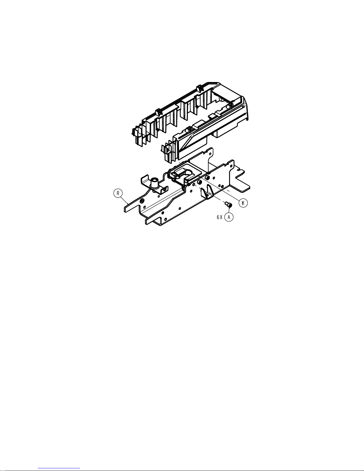
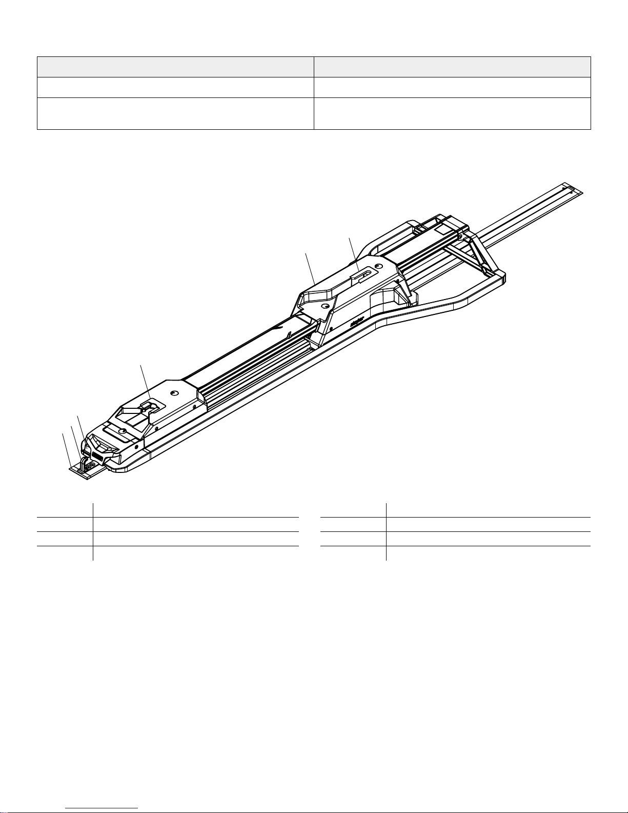
2. Using a ¼'' hex wrench, remove and save the six screws (A) that secure the foot end interface assembly (K) to the foot
Torque item A
to 300 ± 15 in-lb
end weldment (R) (Figure 3).
NNoottee -- Torque item (A) to 300 in-lb.
3. Remove the foot end interface from the lower release link by sliding it toward the head end.
4. Reverse steps to reinstall.
5. Verify proper operation before returning the product to service.
FFiigguurree 33 –– RReeppllaacciinngg tthhee ffoooott eenndd iinntteerrffaaccee aasssseemmbbllyy
IInndduuccttiivvee pprriimmaarryy bbooaarrdd rreeppllaacceemmeenntt ((ooppttiioonnaall))
TToooollss RReeqquuiirreedd::
• T27 Torx driver
PPrroocceedduurree::
1. Unsnap the floor plate cover to gain access to the electrical connection.
2. Disconnect the red and black wires from the cable harness.
3. Using a T27 Torx driver, remove and save the six screws that secure the foot end top cover to the foot end bottom
cover.
4. Using a T27 Torx driver, remove the two screws (A) that secure the inductive charging assembly (C) to the foot end
weldment (Figure 4).
5. Remove the inductive charging assembly.
6. Remove the inductive primary board from the charging enclosure. Discard the inductive primary board.
NNoottee -- Do not dispose of as unsorted municipal waste. Refer to your local distributor for return or collection systems
available in your country.
7. Reverse steps to reinstall.
8. Verify proper operation before returning the product to service.
6392-009-002 Rev E.4 15 EN
Page 20

FFiigguurree 44 –– RReeppllaacciinngg tthhee iinndduuccttiivvee pprriimmaarryy bbooaarrdd
HHeeaadd eenndd pplluunnggeerr rreeppllaacceemmeenntt
TToooollss RReeqquuiirreedd::
• T27 Torx driver
PPrroocceedduurree::
1. Remove the head end interface assembly. (See
2. Using a T27 Torx driver, remove and save the four screws (A) that secure the pin enclosure (C) to the head end
interface (B) (Figure 5).
3. Remove and save the two plunger springs (D) (Figure 5).
4. Remove and save the plunger bracket (F) (Figure 5).
5. Remove and discard the plunger (E) (Figure 5).
6. Reverse steps to reinstall.
7. Verify proper operation before returning the product to service.
Head end interface assembly replacement
(page 14)).
EN 16 6392-009-002 Rev E.4
Page 21

FFiigguurree 55 –– RReeppllaacciinngg tthhee hheeaadd eenndd pplluunnggeerr
FFoooott eenndd lloocckk ppaawwll rreeppllaacceemmeenntt
TToooollss RReeqquuiirreedd::
• T25 Torx driver
• 1/8'' punch
PPrroocceedduurree::
1. Remove the foot end interface assembly. (See
2. Using a 1/8'' punch, push the dowel pin (B) out of the release latch arm (G) (Figure 6). Save the dowel pin.
3. Using a T25 Torx driver, remove and save the six screws (A) that secure the pivot bracket to the foot end interface (C)
(Figure 6).
4. Remove and discard the lock pawl (D) (Figure 6).
NNoottee -- Make sure that the pawl spring (F) remains in place when you remove the lock pawl (Figure 6).
5. Reverse steps to reinstall.
NNoottee -- Fully insert the dowel pin during reassembly.
6. Verify proper operation before returning the product to service.
Foot end interface assembly replacement
(page 14)).
6392-009-002 Rev E.4 17 EN
Page 22

FFiigguurree 66 –– RReeppllaacciinngg tthhee ffoooott eenndd lloocckk ppaawwll
SSaaffeettyy bbaarr rraaiill ssuuppppoorrtt rreeppllaacceemmeenntt
TToooollss rreeqquuiirreedd::
• T27 Torx driver
• Tape measure
PPrroocceedduurree::
1. Using a T27 Torx driver, remove and save the two screws (A) that secure the safety bar rail support (B) to the safety bar
rail (C) (Figure 7).
FFiigguurree 77 –– RReeppllaacciinngg tthhee ssaaffeettyy bbaarr rraaiill ssuuppppoorrtt
2. Using a T27 Torx driver, remove and save the two screws (D) that secure the safety bar rail support (B) to the guide rails
(E) (Figure 7). Discard the safety bar rail support.
3. Using a tape measure, make sure that the tube connector (F) is secured into the guide rails (E) at a depth of 0.75 ±
0.125 in. (Figure 8).
EN 18 6392-009-002 Rev E.4
Page 23

NNoottee -- If the tube connector (F) is not at the required depth, use the removed screw (D) to screw into the tube connector
and adjust as required.
FFiigguurree 88 –– AAddjjuussttiinngg tthhee ttuubbee ccoonnnneeccttoorr
4. Reverse steps to reinstall.
NNoottee -- During reinstallation, make sure that you do not overtighten the screws (D) or you will have to readjust the tube
connectors (F).
5. Verify proper operation before returning the product to service.
FFoooott eenndd ccoovveerr aasssseemmbbllyy rreeppllaacceemmeenntt
TToooollss rreeqquuiirreedd::
• T27 Torx driver
• 15/16'' hex wrench
• 3/8'' Allen wrench
PPrroocceedduurree::
1. Using a T27 Torx driver, remove and save the four socket head cap screws (A) that secure the foot end cover assembly
(B) to the transfer (Figure 9).
2. Using a T27 Torx driver, remove and save the two button head cap screws (C) that secure the foot end cover assembly
to the foot end nose assembly (D) (Figure 9).
3. Remove the foot end cover assembly by sliding it toward the head end of the vehicle patient compartment.
4. Reverse steps 1-3 to reinstall the foot end cover assembly.
6392-009-002 Rev E.4 19 EN
Page 24
A
B
C
D
A
C
FFiigguurree 99 –– FFoooott eenndd ccoovveerr aasssseemmbbllyy
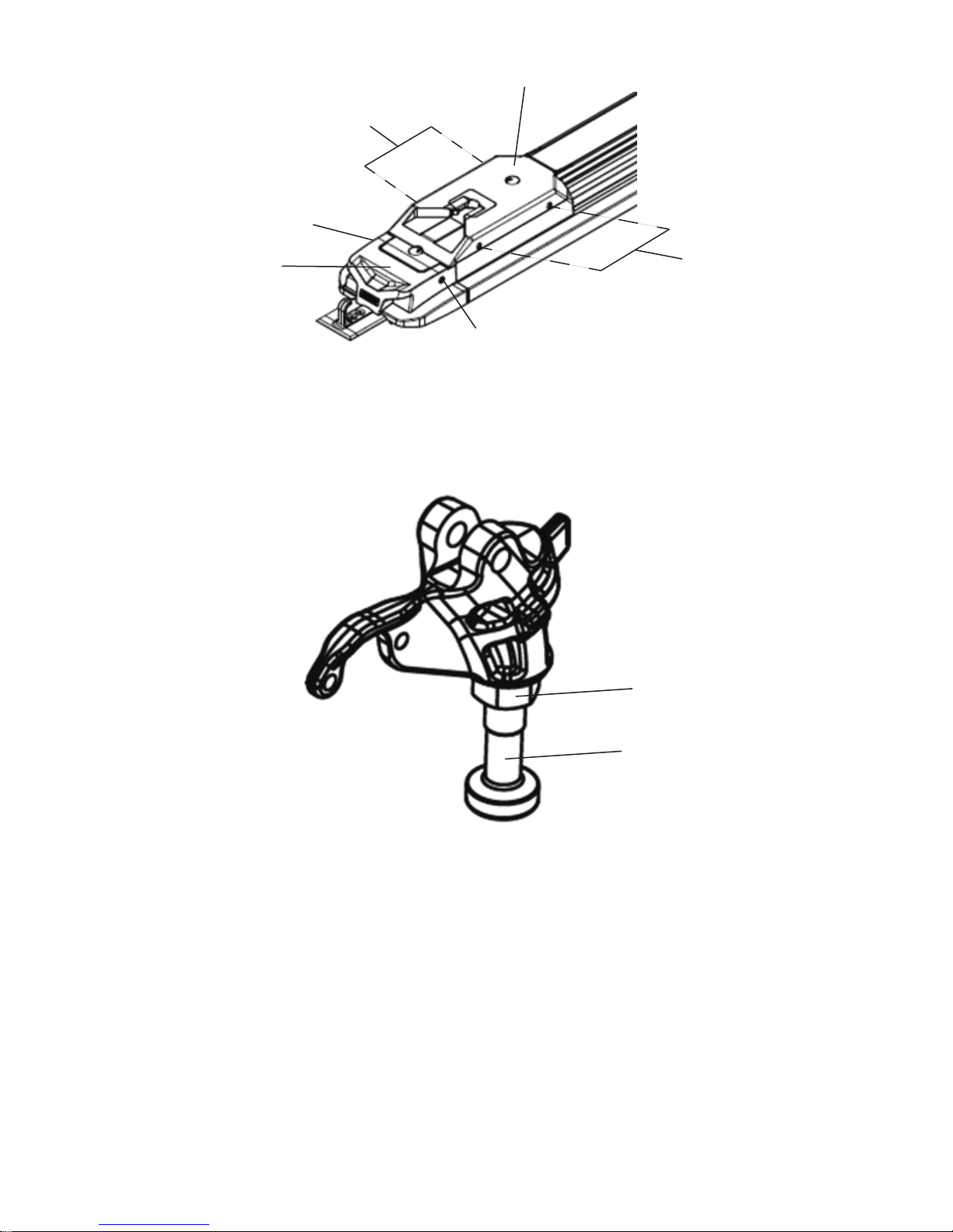
E
F
5. Using a 15/16'' hex wrench, loosen the locknut (E) that secures the pin (F) to the head end forging assembly (Figure 10).
6. Using a 3/8'' Allen wrench, adjust the pin so there is maximum clearance between the foot end cover assembly during
loading and unloading.
NNoottee -- The pin must lock into the head end of the fastener while loaded.
7. Using a 15/16'' hex wrench, tighten the locknut that secures the pin to the head end forging assembly.
8. Verify proper operation of the product before returning it to service.
NNoottee -- You must repair the cot and PPeerrffoorrmmaannccee--LLOOAADD to avoid recurring damage to the foot end cover assembly.
EN 20 6392-009-002 Rev E.4
FFiigguurree 1100 –– HHeeaadd eenndd ffoorrggiinngg aasssseemmbbllyy
Page 25
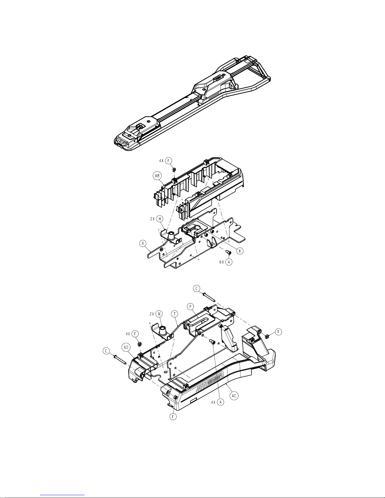
PPeerrffoorrmmaannccee--LLOOAADD aasssseemmbbllyy
Torque item A
to 300 ± 15 in-lb
Torque item A
to 300 ± 15 in-lb
6392-001-010 Rev B (Reference only)
6392-009-002 Rev E.4 21 EN
Page 26
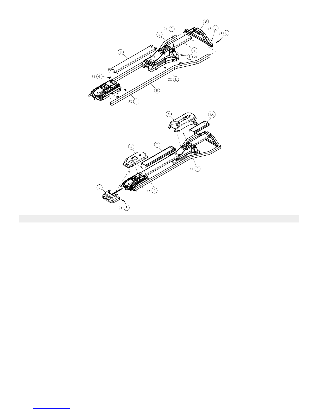
IItteemm NNuummbbeerr NNaammee QQuuaannttiittyy
A 0004-270-000 Socket head cap screw 10
B 0004-376-000 Button head cap screw 2
C 0004-387-000 Button head cap screw 4
D 0004-589-000 Button head cap screw 8
E 0007-052-000 Truss head Torx screw 8
F 0015-096-000 Square nut 10
G 0023-350-000 Pan head thread-cutting tapping screw 4
H 6392-001-012 Assembly, floor plate bolt 4
J 6392-001-021 Assembly, foot end cover 1
K 6392-001-022 Assembly, foot end interface 1
L 6392-001-023 Assembly, foot end nose 1
M 6392-001-025 Assembly, guide rail 2
N 6392-001-031 Assembly, head end cover 1
P 6392-001-032 Assembly, head end interface 1
R 6392-001-052 Weldment, foot end 1
T 6392-001-053 Weldment, head end 1
U 6392-001-102 Safety bar rail, long 1
V 6392-001-103 Safety bar rail, short 1
W 6392-001-104 Safety bar rail support 1
Y 6392-001-105 Safety bar rail cover, long 1
AA 6392-001-106 Safety bar rail cover, short 1
EN 22 6392-009-002 Rev E.4
Page 27

IItteemm NNuummbbeerr NNaammee QQuuaannttiittyy
AB 6392-001-208 Foot end cover, bottom 1
AC 6392-001-303 Head end cover, patient left 1
AD 6392-001-304 Head end cover, patient right 1
6392-009-002 Rev E.4 23 EN
Page 28
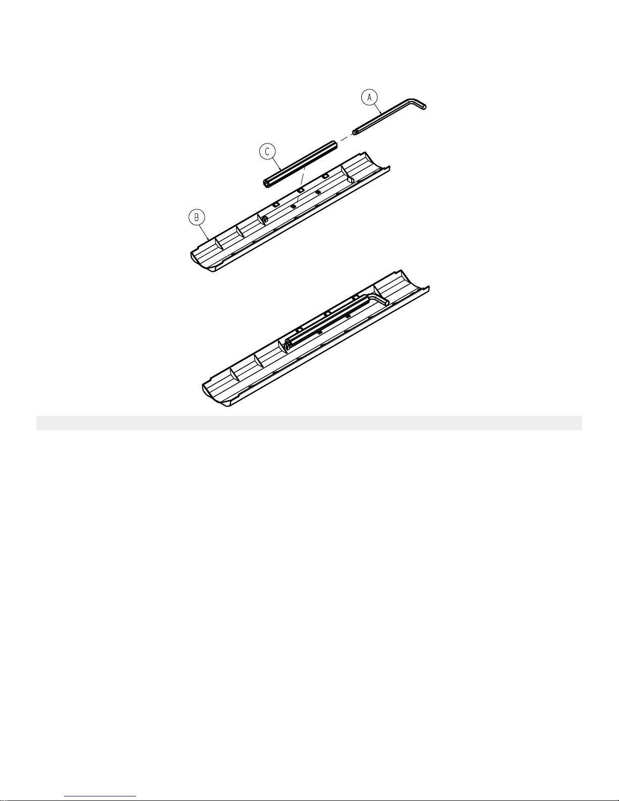
CCeenntteerr ccoovveerr aasssseemmbbllyy
6392-001-011 Rev A (Reference only)
IItteemm NNuummbbeerr NNaammee QQuuaannttiittyy
A 0057-011-000 3/8'' Hex wrench, ball end 1
B 6392-001-403 Floor plate cover 1
C 6392-001-406 Removal tool extension 1
EN 24 6392-009-002 Rev E.4
Page 29
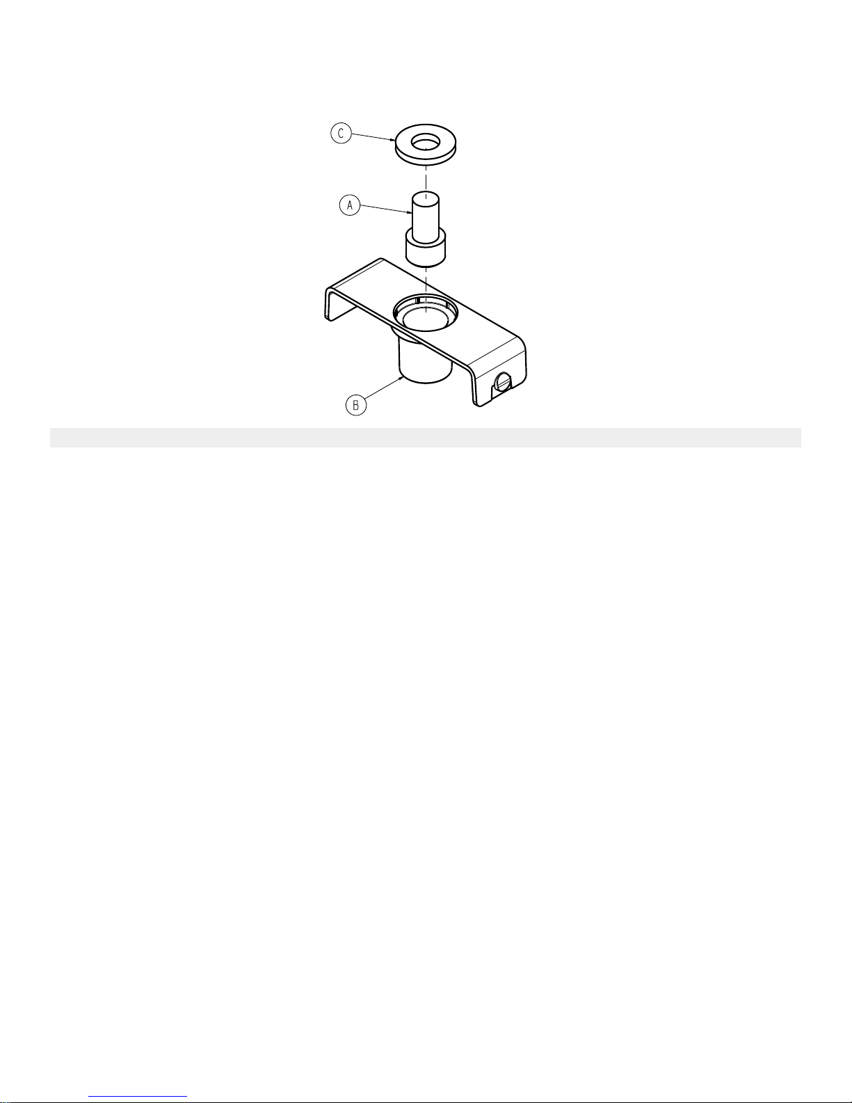
FFlloooorr ppllaattee bboolltt aasssseemmbbllyy
6392-001-012 Rev A (Reference only)
IItteemm NNuummbbeerr NNaammee QQuuaannttiittyy
A 0004-910-000 Socket head cap screw 1
B 6392-001-142 Floor plate bolt holder 1
C 6392-001-143 Washer, bolt holder 1
6392-009-002 Rev E.4 25 EN
Page 30
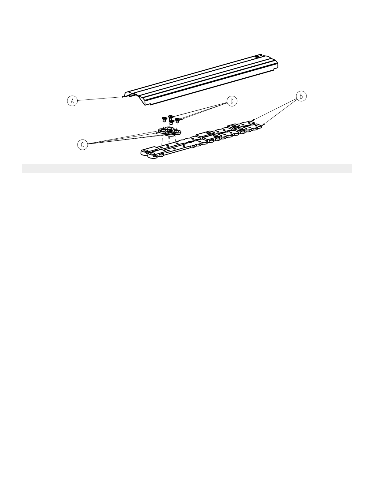
IInnssttaallll kkiitt aasssseemmbbllyy
6392-001-014 Rev A (Reference only)
IItteemm NNuummbbeerr NNaammee QQuuaannttiittyy
A 6392-001-011 Center cover assembly 1
B 6392-001-400 Cleat 2
C 6392-001-401 Cleat locator washer 4
D 0001-194-000 Flat head cap screw 4
EN 26 6392-009-002 Rev E.4
Page 31

IInndduuccttiivvee cchhaarrggiinngg ooppttiioonn
6392-001-015 Rev B (Reference only)
IItteemm NNuummbbeerr NNaammee QQuuaannttiittyy
A 0004-589-000 Button head cap screw 2
B 0015-096-000 Square nut 2
C 6392-001-041 Inductive charging assembly 1
D 0058-394-000 Cable clip 1
6392-009-002 Rev E.4 27 EN
Page 32

FFoooott eenndd ccoovveerr aasssseemmbbllyy
6392-001-021 Rev A (Reference only)
IItteemm NNuummbbeerr NNaammee QQuuaannttiittyy
A 0011-642-000 Plain washer 2
B 0023-349-000 Pan head thread forming screw 2
C 0038-905-000 Spin cap spring 2
D 6392-001-108 Top cover, foot end 1
E 6392-001-309 Spin cap 2
EN 28 6392-009-002 Rev E.4
Page 33

FFoooott eenndd iinntteerrffaaccee aasssseemmbbllyy
6392-001-022 Rev A (Reference only)
IItteemm NNuummbbeerr NNaammee QQuuaannttiittyy
A 0004-442-000 Button head cap screw 6
B 0026-556-000 Dowel pin 1
C 6392-001-202 Interface, foot end 1
D 6392-001-250 Lock pawl, foot end 2
E 6392-001-251 Pivot bracket, foot end interface 1
F 6392-001-252 Pawl spring 2
G 6392-001-257 Release latch link arm 1
6392-009-002 Rev E.4 29 EN
Page 34

FFoooott eenndd nnoossee aasssseemmbbllyy
6392-001-023 Rev A (Reference only)
EN 30 6392-009-002 Rev E.4
Page 35

IItteemm NNuummbbeerr NNaammee QQuuaannttiittyy
A 0023-167-000 Pan head thread forming screw 4
B 0026-316-000 Clevis pin 1
C 6392-001-205 Nose cover 1
D 6392-001-253 Thick release spring 1
E 6392-001-254 Release pivot arm 1
F 6392-001-255 Release button 1
G 6392-001-256 Release lower link 1
H 6392-001-258 Release housing 1
J 6392-001-259 Thin long release spring 1
6392-009-002 Rev E.4 31 EN
Page 36

GGuuiiddee rraaiill aasssseemmbbllyy
6392-001-025 Rev A (Reference only)
IItteemm NNuummbbeerr NNaammee QQuuaannttiittyy
A 0018-046-000 Tube connector 1
B 6392-001-050 Weldment, guide rail 1
EN 32 6392-009-002 Rev E.4
Page 37

HHeeaadd eenndd ccoovveerr aasssseemmbbllyy
6392-001-031 Rev A (Reference only)
IItteemm NNuummbbeerr NNaammee QQuuaannttiittyy
A 0011-642-000 Plain washer 2
B 0023-349-000 Pan head thread forming screw 2
C 0038-905-000 Spin can spring 2
D 6392-001-109 Head end top cover 1
E 6392-001-309 Spin cap 2
6392-009-002 Rev E.4 33 EN
Page 38

HHeeaadd eenndd iinntteerrffaaccee aasssseemmbbllyy
6392-001-032 Rev A (Reference only)
IItteemm NNuummbbeerr NNaammee QQuuaannttiittyy
A 0004-442-000 Button head cap screw 4
B 6392-001-302 Head end interface 1
C 6392-001-305 Head end pin closure 1
D 6392-001-306 Plunger spring 2
E 6392-001-307 Head end plunger 1
F 6392-001-308 Head end plunger bracket 1
EN 34 6392-009-002 Rev E.4
Page 39

IInndduuccttiivvee cchhaarrggiinngg aasssseemmbbllyy
6392-001-041 Rev B (Reference only)
IItteemm NNuummbbeerr NNaammee QQuuaannttiittyy
A 6390-001-133 Anchor primary coil 1
B 6390-001-147 Inductive primary board 1
C 6392-001-150 Inductive charging enclosure 1
6392-009-002 Rev E.4 35 EN
Page 40

HHeeaadd eenndd hhiittcchh aasssseemmbbllyy
6392-001-061 Rev A (Reference only)
IItteemm NNuummbbeerr NNaammee QQuuaannttiittyy
A 6392–001-054 Head end hitch weldment 1
B 6392-001-500 Head end hitch pin 1
C 0016-019-000 Nylock hex nut 1
EN 36 6392-009-002 Rev E.4
Page 41

HHeeaadd eenndd ffoorrggiinngg aasssseemmbbllyy
6392-001-062 Rev A (Reference only)
IItteemm NNuummbbeerr NNaammee QQuuaannttiittyy
A 6392-001-510 Machined forging 1
B 6392-001-500 Head end hitch pin 1
C 0016-323-000 Hex flange serrated lock nut 1
6392-009-002 Rev E.4 37 EN
Page 42

EEMMCC iinnffoorrmmaattiioonn
GGuuiiddaannccee aanndd mmaannuuffaaccttuurreerr’’ss ddeeccllaarraattiioonn -- eelleeccttrroommaaggnneettiicc eemmiissssiioonnss
PPeerrffoorrmmaannccee--LLOOAADD is intended for use in the electromagnetic environment specified below. The customer or the user
of PPeerrffoorrmmaannccee--LLOOAADD should assure that it is used in such an environment.
EEmmiissssiioonnss tteesstt
RF Emissions
CISPR 11
RF Emissions
CISPR 11
RReeccoommmmeennddeedd sseeppaarraattiioonnss ddiissttaanncceess bbeettwweeeenn ppoorrttaabbllee aanndd mmoobbiillee RRFF ccoommmmuunniiccaattiioonnss eeqquuiippmmeenntt aanndd
PPeerrffoorrmmaannccee--LLOOAADD is intended for use in an electromagnetic environment in which radiated RF disturbances are
controlled. The customer or the user of PPeerrffoorrmmaannccee--LLOOAADD can help prevent electromagnetic interferences by
maintaining a minimum distance between portable and mobile RF communications equipment (transmitters) and
PPeerrffoorrmmaannccee--LLOOAADD as recommended below, according to the maximum output power of the communications
equipment.
RRaatteedd mmaaxxiimmuumm oouuttppuutt
ppoowweerr ooff ttrraannssmmiitttteerr
CCoommpplliiaannccee EElleeccttrroommaaggnneettiicc eennvviirroonnmmeenntt
The PPeerrffoorrmmaannccee--LLOOAADD system must emit
Group 2
Class A
PPeerrffoorrmmaannccee--LLOOAADD
SSeeppaarraattiioonn ddiissttaannccee aaccccoorrddiinngg ttoo ffrreeqquueennccyy ooff ttrraannssmmiitttteerr
electromagnetic energy in order to perform its
intended function. Nearby electronic
equipment may be affected.
The PPeerrffoorrmmaannccee--LLOOAADD system is suitable
for use in all establishments other than
domestic and those directly connected to the
public low-voltage power supply network that
supplies buildings used for domestic
purposes.
mm
WW
0.01 0.12 0.035 0.07
0.1 0.38 0.11 0.22
1 1.2 0.35 0.7
10 3.8 1.1 2.2
100 12 3.5 7
For transmitters rated at a maximum output power not listed above, the recommended separation distance d in meters
(m) can be estimated using the equation applicable to the frequency of the transmitter, where P is the maximum output
power rating of the transmitter in watts (W) according to the transmitter manufacturer. Note 1: At 80 MHz and 800 MHz,
the separation distance for the higher frequency range applies. Note 2: These guidelines may not apply in all situations.
Electromagnetic propagation is affected by absorption and reflection from structures, objects, and people.
GGuuiiddaannccee aanndd mmaannuuffaaccttuurreerr’’ss ddeeccllaarraattiioonn -- eelleeccttrroommaaggnneettiicc iimmmmuunniittyy
PPeerrffoorrmmaannccee--LLOOAADD is suitable for use in the electromagnetic environment specified below. The customer or the user of
PPeerrffoorrmmaannccee--LLOOAADD should assure that it is used in such an environment.
IImmmmuunniittyy tteesstt
115500 kkHHzz ttoo 8800 MMHHzz
dd==((11..22)) ((√√PP))
EENN//IIEECC 6600660011 tteesstt lleevveell
8800 MMHHzz ttoo 880000 MMHHzz
dd==((..1188)) ((√√PP))
CCoommpplliiaannccee lleevveell
880000 MMHHzz ttoo 22..55 GGHHzz
dd==((..3355)) ((√√PP))
EElleeccttrroommaaggnneettiicc
eennvviirroonnmmeenntt--gguuiiddaannccee
EN 38 6392-009-002 Rev E.4
Page 43

GGuuiiddaannccee aanndd mmaannuuffaaccttuurreerr’’ss ddeeccllaarraattiioonn -- eelleeccttrroommaaggnneettiicc iimmmmuunniittyy
Electrostatic discharge
(ESD)
IEC 61000-4-2
Power frequency (50/60 Hz)
magnetic field
IEC 61000-4-8
+8 kV contact
+15 kV air
+8 kV contact
+15 kV air
30 A/m 30 A/m
Floors should be wood,
concrete, or ceramic tile. If
floors are covered with
synthetic material, the
relative humidity should be
at least 30%.
Power frequency magnetic
fields should be at levels
characteristic of a typical
location in a typical
commercial or hospital
environment.
NNoottee:: U
is the a.c. mains voltage before applications of the test level.
T
Conducted RF
IEC 61000-4-6
Radiated RF
IEC 61000-4-3
3 Vrms
150 kHz to 80 MHz
10 V/m
80 MHz to 2.5 GHz
3 Vrms
10 V/m
Portable and mobile RF
communications equipment
should be used no closer to
any part of PPeerrffoorrmmaannccee-LLOOAADD, including cables,
than the recommended
separation distance
calculated from the equation
appropriate for the
frequency of the transmitter.
Recommended separation
distance
P
D=(.35) (√
)
80 MHz to 800 MHz
D=(0.70) (√
P
)
800 MHz to 2.5 GHz
where
P
is the maximum
output power rating of the
transmitter in watts (W)
according to the transmitter
manufacturer and
d
is the
recommended separation
distance in meters (m).
6392-009-002 Rev E.4 39 EN
Field strengths from fixed
RF transmitters, as
determined by an
electromagnetic site
a
should be less than the
compliance level in each
frequency range.
b
Interference may occur in
the vicinity of equipment
marked with the following
symbol:
Page 44

GGuuiiddaannccee aanndd mmaannuuffaaccttuurreerr’’ss ddeeccllaarraattiioonn -- eelleeccttrroommaaggnneettiicc iimmmmuunniittyy
NNoottee 11:: At 80 MHz and 800 MHz, the higher frequency range applies.
NNoottee 22:: These guidelines may not apply in all situations. Electromagnetic propagation is affected by absorption and
reflection from structures, objects, and people.
a
Field strengths from fixed transmitters, such as base stations for radio (cellular/cordless) telephones and land mobile
radios, amateur radio, AM and FM radio broadcast, and TV broadcast cannot be predicted theoretically with accuracy. To
assess the electromagnetic environment due to fixed RF transmitters, an electromagnetic site survey should be
considered. If the measured field strength in the location in which PPeerrffoorrmmaannccee--LLOOAADD is used exceeds the applicable
RF compliance level above, the PPeerrffoorrmmaannccee--LLOOAADD system should be observed to verify normal operation. If abnormal
performance is observed, additional measures may be necessary, such as reorienting or relocating PPeerrffoorrmmaannccee-LLOOAADD.
b
Over the frequency range 150 kHz to 80 MHz, field strengths should be less than 3 V/m.
EN 40 6392-009-002 Rev E.4
Page 45

Page 46

Stryker Medical
3800 E. Centre Avenue
Portage, MI 49002
USA
6392-009-002 Rev E.4
2018/06
WCR: AA.5
 Loading...