

Page 1

P100 Powered Support Surface
2880
Operations/Maintenance Manual
2017/12 476004 - 5210 V1.5 www.stryker.com
Page 2

Page 3

Table of Contents
Symbols and Definitions.................................................................................4
Symbols ..........................................................................................4
Warning/Caution/Note Definition .....................................................................5
Technical Specification..................................................................................6
Introduction............................................................................................7
Contraindications...................................................................................7
Intended Use of Product.............................................................................7
Expected Service Life...............................................................................7
Contact Information.................................................................................8
Product Serial Number Location/Identification..........................................................8
Summary of Safety Precautions ..........................................................................9
Product Description ...................................................................................10
Control Unit Front..................................................................................10
Control Unit Rear ..................................................................................10
P100.............................................................................................10
Control Panel .....................................................................................10
Instructions ...........................................................................................11
Cleaning and Disinfection ..............................................................................12
Troubleshooting .......................................................................................13
Service Information ....................................................................................14
Cover Replacement ...............................................................................14
Air Cell Replacement ..............................................................................14
Control Unit Replacement ..........................................................................14
Hose Replacement ................................................................................14
Preventive Maintenance ................................................................................15
Checklist .........................................................................................15
Appendix A: EMC Information ...........................................................................17
Guidance and Manufacturer’s Declaration- Electromagnetic Emissions:...................................17
Guidance and Manufacturer’s Declaration- Electromagnetic Immunity:....................................18
Warranty .............................................................................................20
Limited Warranty ..................................................................................20
To Obtain Parts and Service ........................................................................20
Return Authorization ...............................................................................20
Damaged Merchandise ............................................................................20
International warranty clause ........................................................................20
www.stryker.com 476004-5210 V1.5 3
Page 4

SYMBOLS
SN
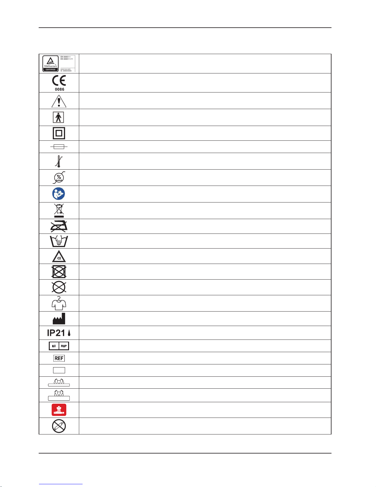
Symbols and Definitions
TUV marking
CE marking
Warning / Caution, consult accompanying documentation
Type BF equipment
Double Insulation
Fuse
Temperature Limitation, Operating: 10°C to 40°C, Storage: -15°C to 50°C
Humidity Limitation, 10% - 90%
Refer to instruction manual/ booklet
Disposal: Contact local distributor who will take the necessary steps according to your national
market.
Do Not Iron
Damp Wipe Only
Chlorinated Bleach: concentration less than or equal to 1000 ppm chlorinate or 70% alcohol
Do Not Tumble Dry
Do Not Dry Clean
Allow to Completely Air Dry
Manufacturer
Protected against solid foreign objects of 12,5 mm and greater; Protection against vertically falling
water drops
Authorized representative in the European community
Catalogue Number (model)
Serial Number
Minimum inflation level of the mattress
Maximum inflation level of the mattress
CPR
Do Not Open with Cutter
Return To Table of Contents
4 476004- 5210 V1.5 www.stryker.com
Page 5

Introduction
WARNING/CAUTION/NOTE DEFINITION
The words WARNING, CAUTION and NOTE carry special meanings and should be carefully reviewed.
WARNING
Alerts the reader about a situation which, if not avoided, could result in death or serious injury. It may also describe
potential serious adverse reactions and safety hazards.
CAUTION
Alerts the reader of a potentially hazardous situation which, if not avoided, may result in minor or moderate injury to the
user or patient or damage to the equipment or other property. This includes special care necessary for the safe and
effective use of the device and the care necessary to avoid damage to a device that may occur as a result of use or
misuse.
NOTE
Provides special information to make maintenance easier or important instructions clearer.
www.stryker.com 476004-5210 V1.5 5
Return To Table of Contents
Page 6
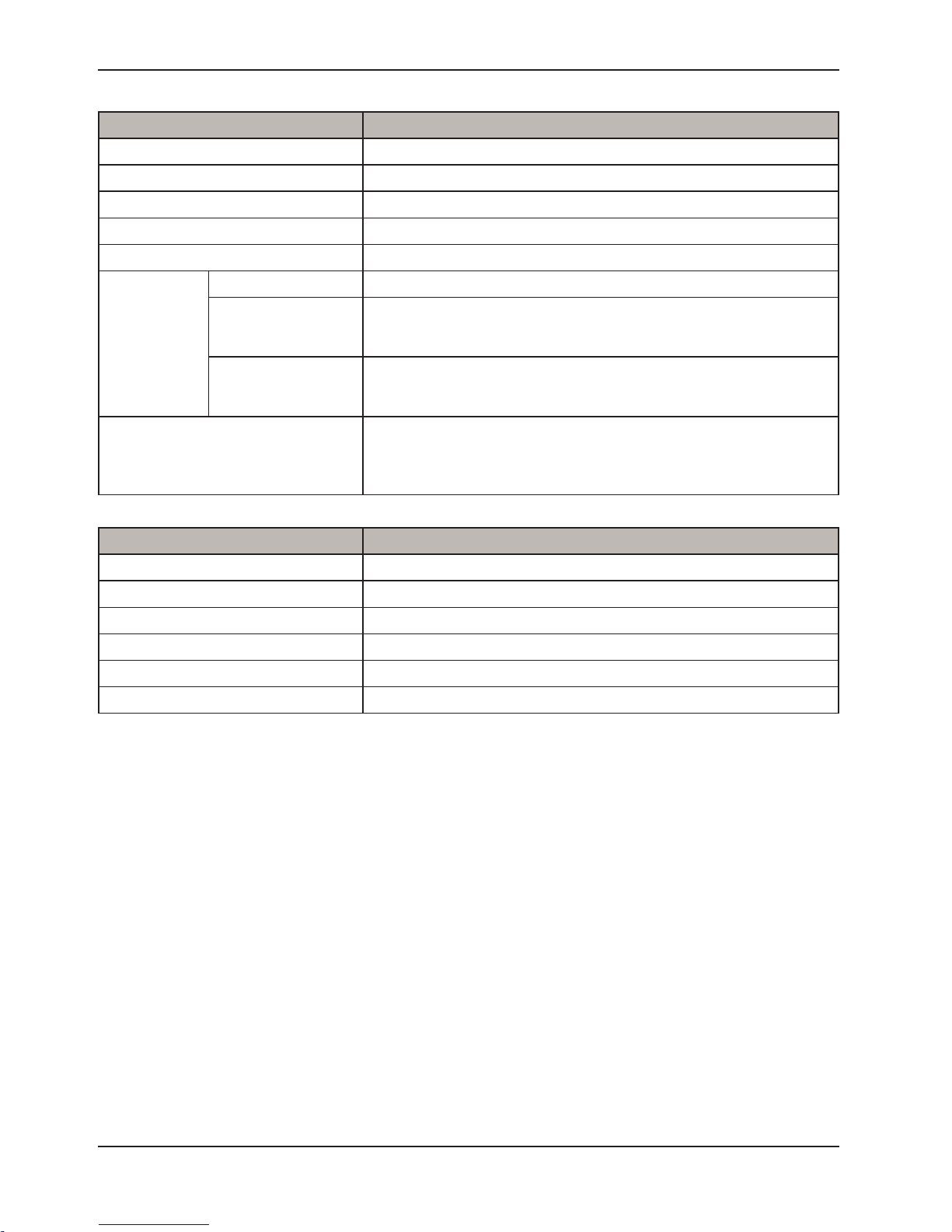
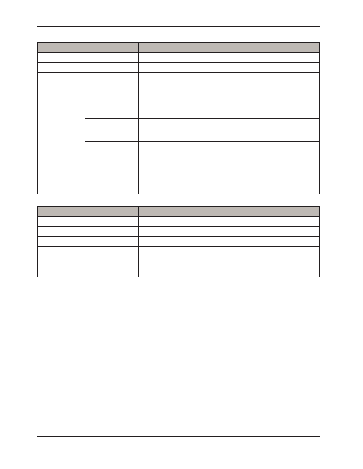
Technical Specification
Item Specification
Power Supply AC230V 50Hz, 0.05A ( for 230V system )
Fuse Rating T1AL, 250V
Dimension (L x W x H) 25 x 12.5 x 8.5 cm / 9.8” x 4.9” x 3.3”
Weight 1.4 kg / 3.1 lbs
Cycle Time 8 min/60 Hz, 9.6 min/50 Hz
Atmospheric Pressure 700 hPa to 1013.25 hPa
• Operation: 10°C to 40°C (50°F to 104°F)
Temperature
Environment
Humidity
Classification
• Storage: -15°C to 50°C (5°F to 122°F)
• Shipping: -15°C to 70°C (5°F to 158°F)
• Operation: 10% to 90% non-condensing
• Storage: 10% to 90% non-condensing
• Shipping: 10% to 90% non-condensing
• Class II, Type BF, IP21
• Applied Part: Air Mattress
• Not suitable for use in the presence of a flammable anesthetic mixture (No AP or APG protection)
Air Mattress Specification
Model P100
Model Number 2880
Flame Retardant Standards EN 597-1 and EN 597-2
Safe Working Load 135 kg / 297 lbs
Dimension (L x W x H) 193 x 89 x 18 cm / 76”x 35” x 7.1”
Weight 5.75 kg / 12.7 lbs
Return To Table of Contents
6 476004- 5210 V1.5 www.stryker.com
Page 7

Introduction
This manual is designed to assist with the operation and maintenance of the P100 Powered Support Surface. Carefully
read this manual thoroughly before using or beginning maintenance on the support surface. To ensure safe operation
of this equipment, it is recommended that methods and procedures are established for educating and training staff on
the safe operation of the support surface.
CONTRAINDICATIONS
Air support therapy is not recommended when spinal stability is a concern. This support surface is not intended to
support a patient in the prone position.
INTENDED USE OF PRODUCT
P100 is a constant low pressure powered support surface intended to provide pressure redistribution to aid in the
prevention and treatment of pressure ulcers. The system consists of a control unit combined with an alternating air
cell mattress. The air cells redistribute the patient’s weight over the surface and aid in the reduction of tissue interface
pressure. It is recommended that the product be operated by personnel who are qualified to perform general nursing
procedures and have received adequate training in the prevention and treatment of pressure ulcers.
This support surface is intended to be used with human patients in a general hospital, nursing home or homecare
environment and for patients at risk of developing pressure ulcers, as well as those who require therapy for pre- existing
pressure ulcers. The safe working load for P100 is 135 kg /297 lbs; the patient must not exceed safe working load
specified by the support surface, frame, and accessories. Patients shall meet the minimum age requirement of 2 years
old.
P100 shall be used with a mattress cover at all times.
The support surface is not intended to be a sterile product nor is it intended to include a measuring function.
EXPECTED SERVICE LIFE
The products are intended to offer safe and reliable operation when in use or installed according to the instructions
provided by Stryker Medical. Stryker Medical recommends that the system be inspected and serviced by authorized
technicians if there are any signs of wear or concerns with device function and indication on products. Otherwise,
service and inspection of the devices generally should not be required. P100 has an expected service life of 2 years.
www.stryker.com 476004-5210 V1.5 7
Return To Table of Contents
Page 8
Introduction
CONTACT INFORMATION
Contact Stryker Customer Service or Technical Support at: (800) 327-0770 or (269) 324-6500.
Stryker Medical
3800 E. Centre Avenue
Portage, MI 49002
USA
Please have the serial number (A) of your Stryker product available when calling Stryker Customer Service or Technical
Support. Include the serial number in all written communication.
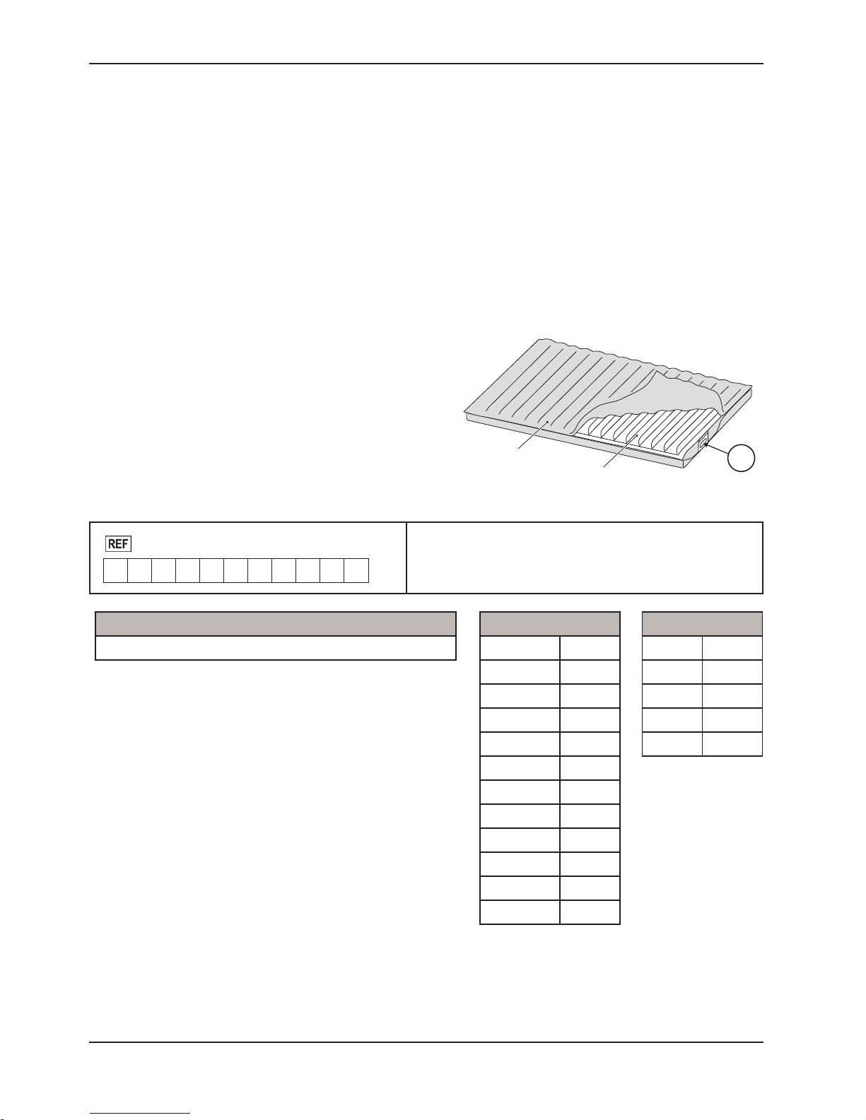
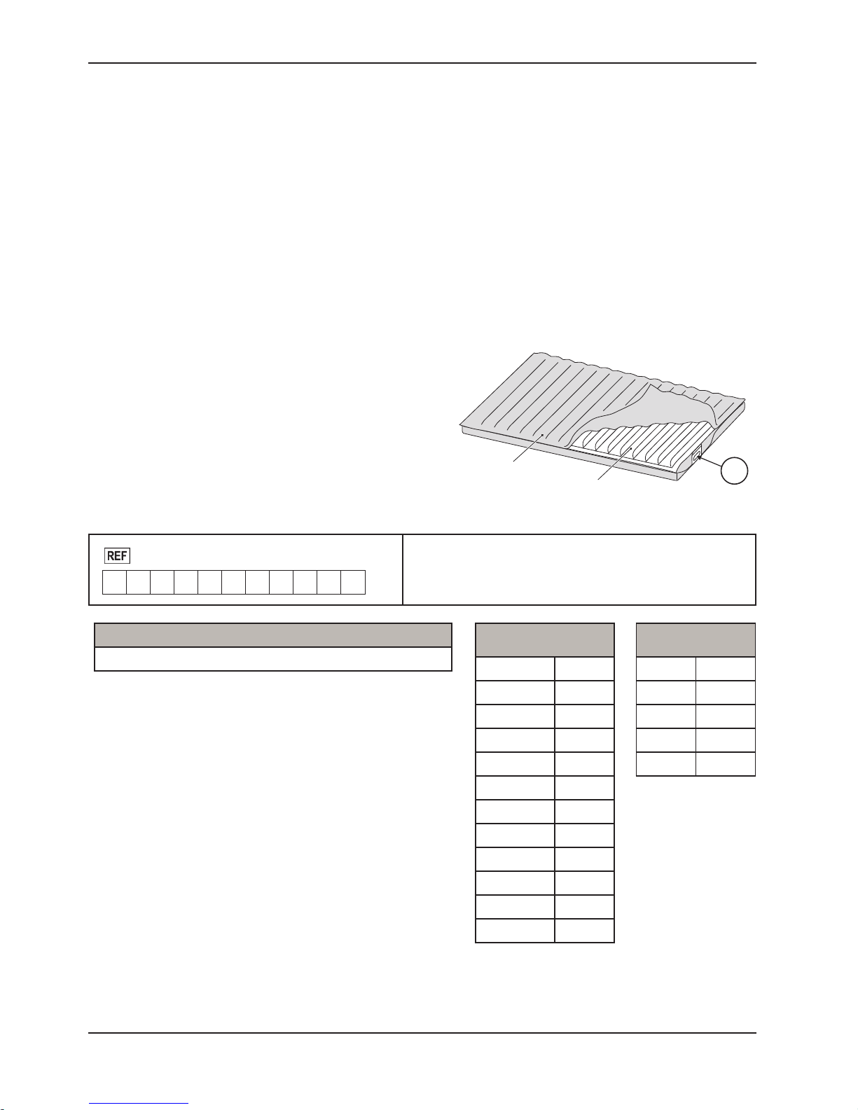
PRODUCT SERIAL NUMBER LOCATION/IDENTIFICATION
The serial number (A) is located at the mattress cover near
foot right corner of the mattress as shown in Figure 1. Also
on the foam crib and air cell with stamp on it, to reference the
serial number, unzip the cover about one foot to access the
foam crib and air cell. The serial number is also located at the
bottom casing of control unit.
▼
Figure 1
Format:
2880
M Y Y M M - S S S S S
Model Number Legend (X)
2880 P100
P100 Mattress
Foam and Air Cell
• M = Mattress
• YY = Year
• MM = Month
• SSSSS = Sequence (Numeric)
Month Legend (MM)
January 01
February 02
March 03
April 04
May 05
June 06
July 07
August 08
September 09
October 10
A
Year Legend (YY)
2012 12
2013 13
2014 14
2015 15
2016 16
Return To Table of Contents
8 476004- 5210 V1.5 www.stryker.com
November 11
December 12
Page 9
Summary of Safety Precautions
WARNING
• Check patient’s skin regularly. Consult physician if any redness or skin break occurs. Serious injury could result if
the patient’s skin condition is left untreated.
• Do not place the control unit in the patient’s bed, in contact with the patient, or under sheets or other coverings.
• Doing so could cause serious injury or could affect control unit performance.
• Do not use in the presence of a flammable anesthetic mixture or with oxygen (O2) or nitrous oxide (N2O).
• Verify bed side rails are compatible with bed frame and existing mattress. A risk assessment must be performed
by a suitably qualified person, especially when side rails are prescribed, to ensure that the bed meets the IEC
60601-2-52 bed standard.
• Use with appropriate top sheet and minimize layers of bedding between patient and mattress.
• Assess patient’s risk of entrapment according to protocols and monitor accordingly.
• Close supervision is necessary when this product is used on or near children. Electrical burns or choking may
result from a child swallowing a small part detached from the device.
• Use this product only for its intended use as described in this manual.
• Do not operate product if the power cord or plug has been damaged.
• Keep the cord away from heated surfaces.
• Never block any air openings of this product or place it on soft surfaces, such as a bed or couch, where openings
may be blocked. Keep the air opening free of lint, hair, and other similar particles.
• Never drop or insert any object into any opening or hose.
• Do not modify this equipment without the authorization of the manufacturer.
• Mattress covers have passed skin sensitization and skin irritation tests. However, if you suspect that you may have
had or are having an allergic reaction, please consult a physician immediately.
• The power cord to the Control Unit should be positioned to avoid a strangulation hazard and/or damage to the cord.
Careful consideration is required when routing the power cable. It is recommended that placing the cord under the
bed frame and attaching it to an electrical outlet at the head of bed.
• Serious injury or death can result from the use (potential entrapment) or non-use (potential patient falls) of siderails
or other restraints. The safe use of the support surface is maximized when used in conjunction with siderails;
there may be an increased risk of falls when siderails are not present. Local policies regarding the use of siderails
should be taken into account. Whether and how to use siderails is a decision that should be based on each patient’s individual needs and should be made by the physician, operators, and responsible parties.
• The risk of entrapment can develop when the support surface is placed on bed frames that leave gaps of even a
few inches between the support surface and the headboard, footboard, and siderails. The support surface is NOT
to be used when such gaps are present.
• When cleaning the support surface, ensure that no liquid is allowed to seep into the zipper area and watershed
cover barrier (underside); fluids allowed to come in contact with the zipper may leak into the support surface.
• Do not expose the mattress to excessive moisture. Personal injury or equipment damage could occur.
• The use of quaternaries containing glycol ethers and/or accelerated hydrogen peroxides may compromise the
cover integrity and legibility.
• Be aware of devices or equipment placed on the top of the support surface. Damage to the surface may occur due
to the weight of the equipment, heat generated by the equipment, or sharp edges on the equipment.
• Do not put overlays or accessories inside the cover. Doing so may reduce pressure redistribution performance.
• It is the responsibility of the caregiver team to evaluate the appropriate CPR protocol to be used with the surface.
• If there is a possibility of electro-magnetic interference with mobile phones, please increase the distance (3.3m)
between devices or turn off the mobile phone.
NOTE
The P100 support surface must be used with a mattress cover at all times. The support surface cover may interact
with all external skin.
www.stryker.com 476004-5210 V1.5 9
Return To Table of Contents
Page 10
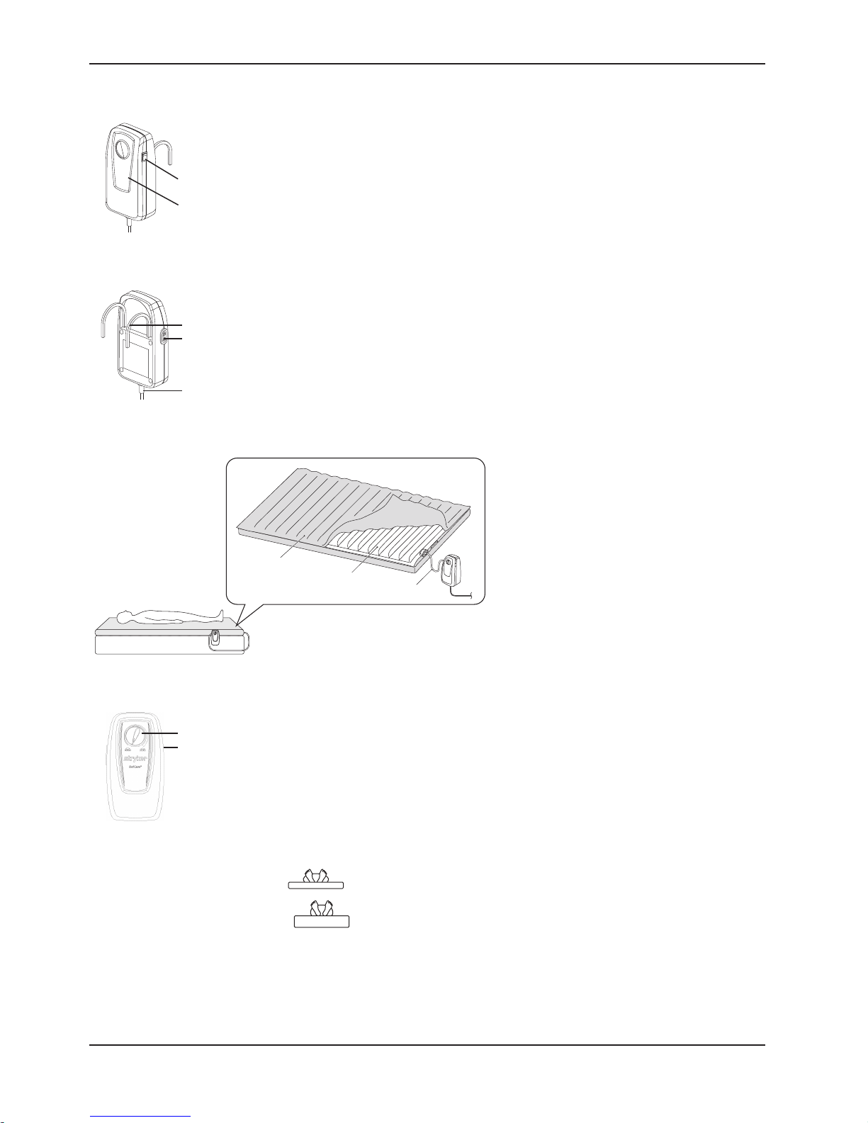
CONTROL UNIT FRONT
Figure 2
◄
1. Power Switch On/Off
2. Front Panel
1
2
CONTROL UNIT REAR
Figure 3
◄
3
4
5
3. Hanger
4. Air Hose Port
5. Power Cord
P100
Product Description
Figure 4
◄
6. P100 Mattress
7. Foam and Air Cell
8. Air Hose
CONTROL PANEL
9
10
6
Figure 5
◄
9. Pressure Adjust Knob
Pressure adjust knob controls the air pressure output. When turning
clockwise, the output pressure will increase. Vice versa for decreasing air
pressure. Please consult your care giver for a suitable setting.
10. Power Switch
To turn on/off the control unit:
a. Power ON/OFF Switch on side of unit.
b. COMFORT CONTROL DIAL adjusts for patient comfort.
Soft(
Firm (
7
)—Minimum inflation level of the mattress
)—Maximum inflation level of the mattress.
8
Return To Table of Contents
10 476004-5210 V1.5 www.stryker.com
Page 11
12
Instructions
1. Place control unit on flat surface or suspend control unit on end of bed using attached hooks. See Figure 2 and
Figure 3. Remove the plug to disconnect the device.
2. Position the mattress on bed frame.
3. Connect the hose assembly between the mattress air cell and the control unit. Unscrew the cap from the air
valve of the mattress and screw the adaptor from control unit onto the air valve tightly.
4. Plug the power cord and adjust the pressure control knob to highest setting for quick inflation and turn control
unit on using green on/off switch. The unit will take approximately 40 minutes to inflate the mattress.
5. After installation, make sure the flap is not folding upwards to avoid fluid seeping through mattress cover.
NOTE
Make sure the control unit is suitable for the local power voltage and frequency.
6. Position patient on the mattress and adjust the pressure control knob for patient comfort.
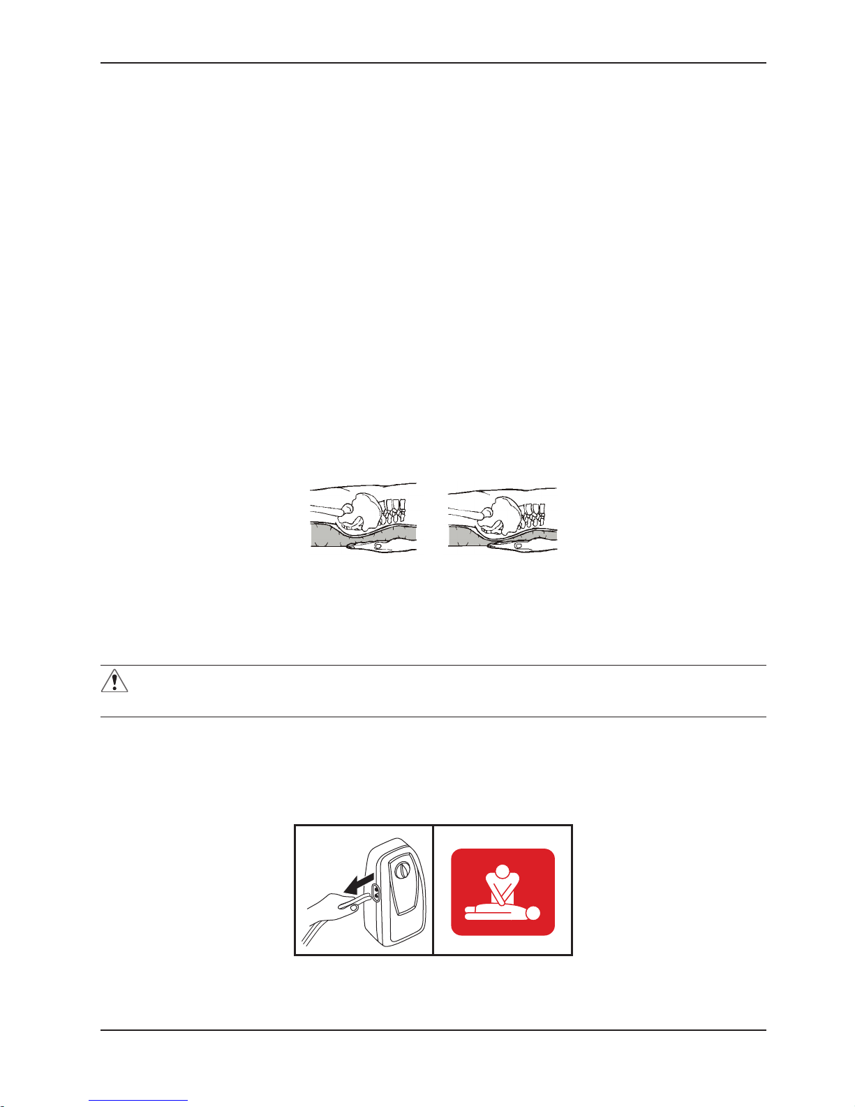
7. A Hand Check must be performed every 8 hours to verify proper operation of the device. See Figure 6.
8. To perform the Hand Check:
With the patient on his or her back, slide hand, flat and palm up, between the overlay and the mattress. Hand
should be directly under the air cell that is under the patient’s buttocks (or other bony area). See Figure 6.
Figure 6
▼
HAND CHECK
Properly inflated Under-inflated
Wait for full inflation of the air cell directly above hand. If the patient’s body is not in direct contact with hand, the system
is operating correctly. If, during full inflation of air cell, the patient’s body is in direct contact with flat hand, the system
is not operating properly. Adjust the pressure control to a higher setting. Wait 10 minutes and repeat the Hand Check.
If the Hand Check fails, check that the hoses are not kinked or pinched. If repeated Hand Check fails and hoses are
not kinked, contact Stryker for further instruction.
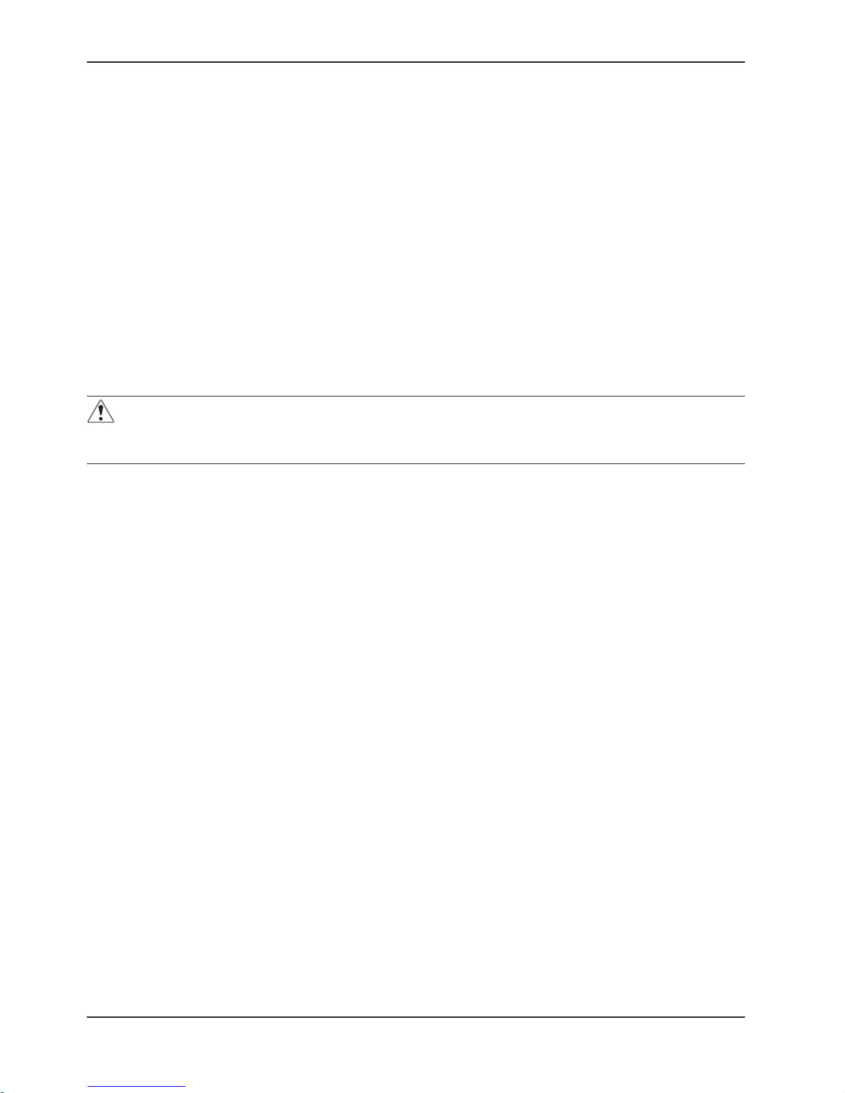
WARNING
Deflate before CPR or CPR could be ineffective.
To deflate mattress for CPR:
Disconnect the hoses from the control unit. See Figure 7. The air cell will deflate in approximately 20 seconds.
Proceed with CPR procedures.
Figure 7
▼
www.stryker.com 476004-5210 V1.5 11
Return To Table of Contents
Page 12
Cleaning and Disinfection
The control unit housing, tubing, and mattress should be cleaned between patients.
• To clean, use water and a clean cloth to wipe down the Control Unit, power cord, hoses, mattress top cover,
middle layer and bottom cover. Do not clean the foam. Do not use abrasive cleaners on the mattress. Note:
Blood and other body fluids must be thoroughly cleaned from all surfaces before applying disinfectants.
• Apply disinfectants to the external surfaces of the control unit, hoses and mattress top cover, middle layer and
bottom cover by wiping. Stryker recommends a chlorine-based solution with a concentration less than or equal to
1000 ppm or 70% alcohol twice a week.
• It is not recommended to disinfect the internal parts of the mattress on a regular basis, but only as needed for
particular instance, the air cell and the middle layer of the cover could be wiped with a cloth and disinfectants as
recommended above.
• Wipe down the mattress with a clean, dry cloth to remove any excess of disinfectant.
• If other detergent or other cleaning agent is used, choose one that will not have adverse chemical effects on the
surface of the plastic case of the control unit, mattress cover and any other component of the device.
• When cleaning the support surface, ensure that no liquid is allowed to seep into the zipper area and watershed
cover barrier (underside); fluids allowed to come in contact with the zipper may leak into the support surface.
• Avoid dust and proximity to dusty areas.
• All components should be air dried thoroughly before use.
WARNING
• Do not use phenolic based products for cleaning.
• Do no dry the mattress in direct sunlight.
Return To Table of Contents
12 476004-5210 V1.5 www.stryker.com
Page 13
Troubleshooting
Problem Solution
Loss of power Check if the plug is connected to mains.
Patient is bottoming out
Air cells fail to inflate
No air produced from some air
outlets of the air tube connector
Pressure setting might be inadequate for the patient. Adjust comfort range 1 to 2
levels higher and wait for a few minutes for best comfort.
Make sure the air hose is not kinked, cracked, or split. Verify that the power
switch is illuminated, signifying the control unit has power. Verify that the air
hoses are fully inserted with a positive connection.
This is normal since there is alternating mode. Air outlets take turns to produce
air during their cycle time.
www.stryker.com 476004-5210 V1.5 13
Return To Table of Contents
Page 14

Service Information
COVER REPLACEMENT
Tools Required: None
Procedure:
1. Disconnect the hose assembly between the mattress air cell and control unit.
2. Unzip the top cover.
3. Remove the air cell.
4. Unzip the middle layer at the patient’s right side and then remove the foam from the bottom part.
5. Discard the old cover.
6. Place the new cover, unzipped and open the top cover and middle layer.
7. Carefully slide the foam to the bottom part and zip the middle layer to close.
8. Carefully place the air cell on the top part and zip the cover to close.
9. Verify proper operation of the unit before returning it to service.
AIR CELL REPLACEMENT
Tools Required: None
Procedure:
1. Disconnect the hose assembly from the air valve of mattress.
2. Unzip the top cover.
3. Remove and discard the old air cell.
4. Place the new air cell and zip the cover to close
CONTROL UNIT REPLACEMENT
Tools Required: None
Procedure:
1. Disconnect the plug from mains power and hose.
2. Discard the old control unit.
3. Place the new control unit and connect the plug to mains power and hose.
HOSE REPLACEMENT
Tools Required: None
Procedure:
1. Disconnect the hose from control unit and mattress.
2. Discard the old hose.
3. Connect the new hose to control unit and mattress.
Return To Table of Contents
14 476004-5210 V1.5 www.stryker.com
Page 15
Preventive Maintenance
Preventative maintenance should be performed annually, at a minimum. A preventative maintenance program should
be established for all Stryker Medical equipment. Preventative maintenance may need to be performed more frequently
based on the usage level of the product.
CHECKLIST
_______ Cover zipper opens and closes properly and has no visible damage.
_______ No tears, rips, holes, cracks, or other openings in the mattress cover.
_______ Check labels for legibility, proper adherence, and integrity.
_______ Support surface cover straps and snaps are intact and are not damaged.
_______ Straps properly secure the support surface assembly to the crib.
_______ Foam and other components have not degraded or come apart.
_______ Check main power cord and do not plug if there is an abrasion or excessive wear.
_______ Check airflow from the air hose.
_______ Check the air hose if there is kink or breaks.
_______ Verify proper operation of the unit before returning it to service.
Product Serial Number:
Completed by: _____________________________________________ Date: _______________________
www.stryker.com 476004-5210 V1.5 15
Return To Table of Contents
Page 16
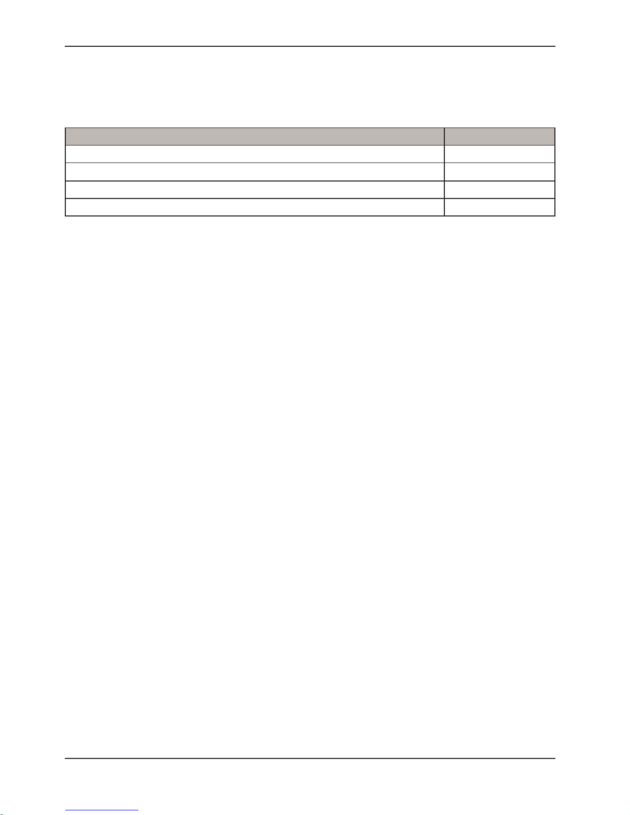
Quick Reference Replacement Parts
The parts and accessories listed on this page are currently available for purchase. Some of the parts identified on the
assembly drawing parts in this manual may not be individually available for purchase. Please call Stryker Customer
service USA at 1-800-327-0770 for availability and pricing.
Part Name Part Number
P100 mattress cover assembly 2880-030-100
Air cell assembly 2880-030-400
P100 control unit 2880-030-500
Air hose, PVC, P100 2880-030-520
Return To Table of Contents
16 476004-5210 V1.5 www.stryker.com
Page 17
Appendix A: EMC Information
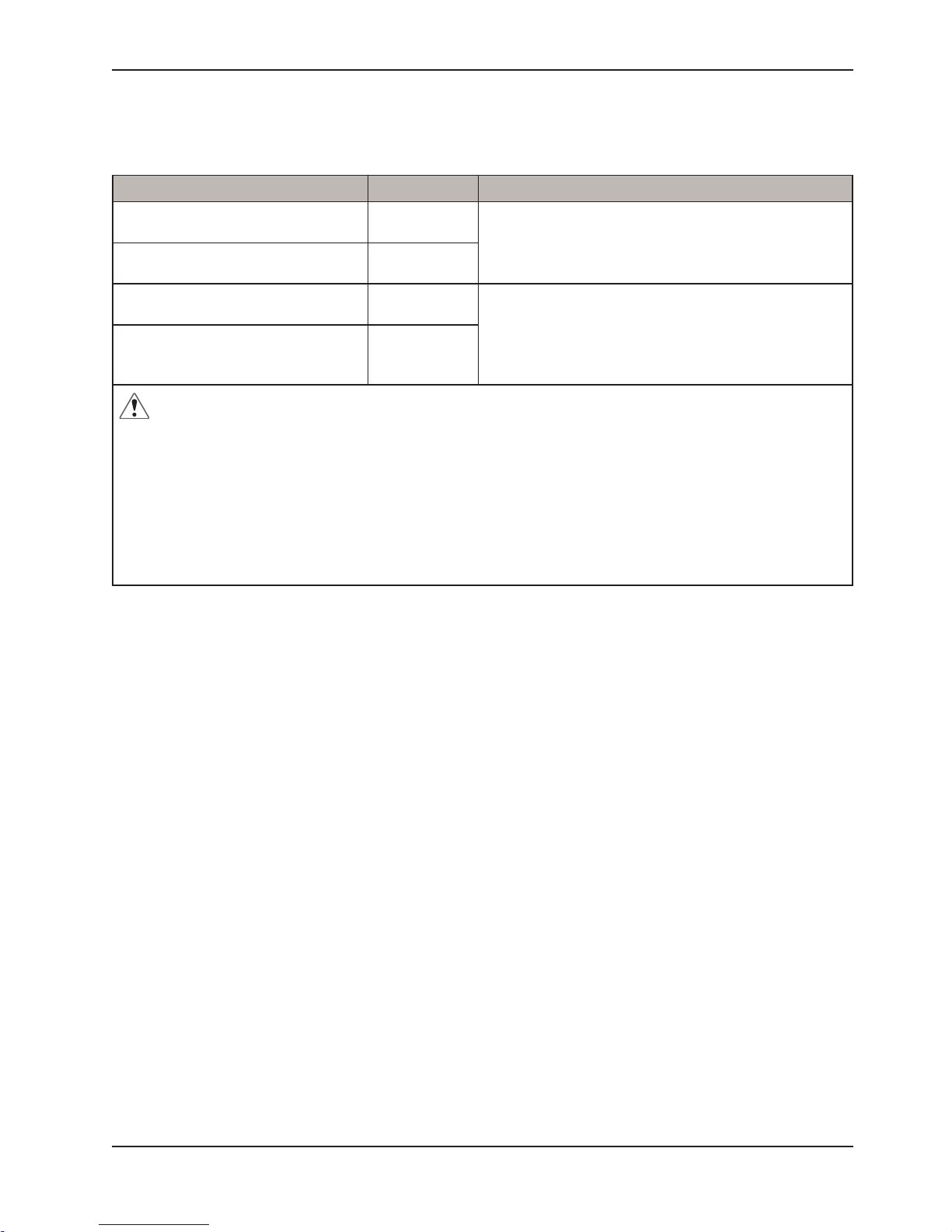
GUIDANCE AND MANUFACTURER’S DECLARATION- ELECTROMAGNETIC EMISSIONS:
This device is intended for use in the electromagnetic environment specified below. The user of this device should make
sure it is used in such an environment.
Emissions Test Compliance Electromagnetic Environment-Guidance
RF emissions
CISP R 11
RF emissions
CISP R 11
Harmonic emissions
IEC61000-3-2
Voltage fluctuations / Flicker
emissions
IEC61000-3-3
WARNING
1. The device should not be used adjacent to or stacked with other equipment. If adjacent or stacked use is
necessary, the device should be observed to verify normal operation in the configuration in which it will be used.
2.Use of accessories, transducers and cables other than those specified or provided by the manufacturer of this
equipment could result in increased electromagnetic emissions or decreased electromagnetic immunity of this
equipment and result in improper operation.
3. Portable RF communications equipment (including peripherals such as antenna cables and external antennas)
should be used no closer than 30 cm (12 inches) to any part of the Pump, including cables specified by the
manufacturer. Otherwise, degradation of the performance of this equipment could result.
Group1
Class B
Class A
Complies
The device uses RF energy only for its internal function.
Therefore, its RF emissions are very low and are not likely
to cause any interference in nearby electronic equipment
The device is suitable for use in all establishments,
including domestic establishments and those directly
connected to the public low-voltage power supply
network
www.stryker.com 476004-5210 V1.5 17
Return To Table of Contents
Page 18
Appendix A: EMC Information
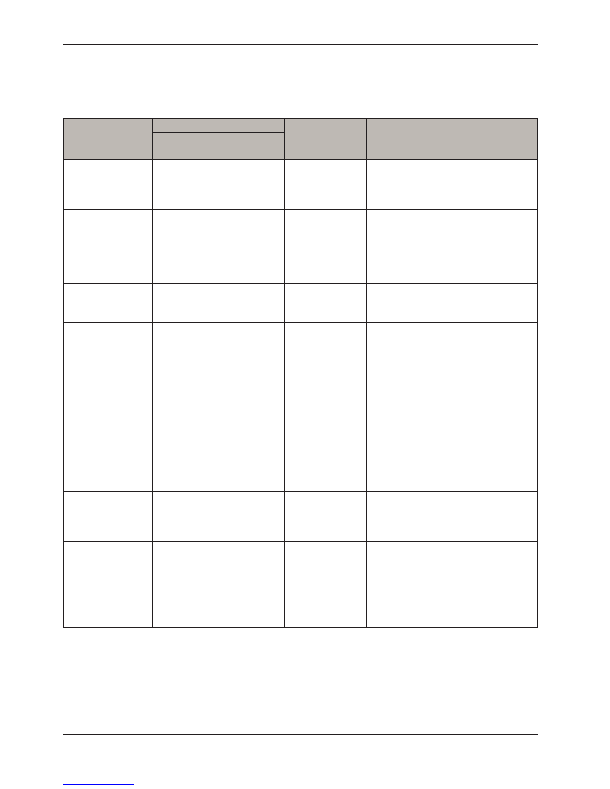
GUIDANCE AND MANUFACTURER’S DECLARATION- ELECTROMAGNETIC IMMUNITY:
This device is intended for use in the electromagnetic environment specified below. The user of this device should make
sure it is used in such an environment.
Basic EMC
standard
Electrostatic
Discharge (ESD)
IEC61000-4-2
Electrical fast
transient/ burst
IEC61000-4-4
Immunity Test Levels Compliance
HOME HEALTHCARE
Levels
ENVIRONMENT
±8kV contact
±15kV air
±2kV for power supply line
±1kV for input/output line
±8kV contact
±15kV air
±2kV for power
supply line
±1kV for input/
output line
Electromagnetic
Environment-Guidance
Floors should be wood, concrete or
ceramic tile. If floors are covered with
synthetic material, the relative humidity
should be at least 30 %.
Mains power quality should be that
of a typical commercial or hospital
environment
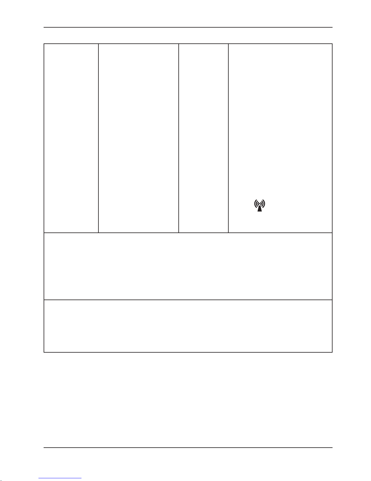
Surge
IEC61000-4-5
Voltage dips, short
interruptions and
voltage variations
on power supply
input lines
IEC61000-4-11
Power frequency
(50/60Hz) magnetic
field
IEC61000-4-8
Conducted RF
IEC 61000-4-6
± 1 kV line(s) to
line(s)
± 2 kV line(s) to earth
Voltage Dips:
i) 100% reduction for 0.5
period,
ii) 100% reduction for 1 period,
iii) 30% reduction for 25/30
period,
Voltage Interruptions:
100% reduction for 250/300
period
± 1 kV line(s) to
line(s)
(1)
230V (U
)
T
Voltage Dips:
i) 100% reduction
for 0.5 period,
ii) 100% reduction
for 1 period,
iii) 30% reduction
for 25/30 period,
Voltage
Mains power quality should be that
of a typical commercial or hospital
environment.
Mains power quality should be that
of a typical commercial or hospital
environment. If the user of this
device requires continued operation
during power mains interruptions, it
is recommended that the device be
powered from an uninterruptible power
supply or a battery.
Interruptions:
100% reduction
for 250/300
period
30 A/m 30 A/m Power frequency magnetic fields should
be at levels characteristic of a typical
location in a typical commercial or
hospital environment.
3 Vrms
0,15 MHz – 80 MHz
6 Vrms in ISM and amateur
radio bands between
0,15 MHz and 80 MHz
80 % AM at 1 kHz
(4)
6Vrms Portable and mobile RF
communications equipment should
be used no closer to any part of this
device, including cables, than the
recommended separation distance
calculated from the equation applicable
to the frequency of the transmitter.
Return To Table of Contents
18 476004-5210 V1.5 www.stryker.com
Page 19
Appendix A: EMC Information
Radiated RF EM
Fields
IEC61000-4-3
10 V/m 80 MHz to 2,7 GHz
80 % AM at 1 kHz
385-6000 MHz, 9-28V/m, 80%
AM(1kHz) pulse mode and
other modulation
10V/m Recommended separation distance
d=√P 150kHz to 80MHz
d=0.6√P 80MHz to 800MHz
d=1.2√P 800 MHz to 2.7G Hz
Where P is the maximum output
power rating of the transmitter
in watts (W) according to the
transmitter manufacturer and d is the
recommended separation distance in
meters (m).
b
Field strengths from fixed RF
transmitters, as determined by an
electromagnetic site survey ,a should be
less than the compliance level in each
frequency ranged.
Interference may occur in the vicinity
of equipment marked with the following
symbol:
NOTE 1: UT is the a.c. mains voltage prior to the application of the test level
NOTE 2: At 80 MHz and 800 MHz, the higher frequency range applies.
NOTE 3: These guidelines may not apply in all situations. Electromagnetic propagation is affected by absorption and
reflection from structures, objects and people
NOTE 4: The ISM (industrial, scientific and medical) bands between 0.15 MHz and 80 MHz are 6.765 MHz to 6.795
MHz; 13.553 MHz to 13.567 MHz; 26.957 MHz to 27.283 MHz; and 40.66 MHz to 40.70 MHz. The amateur radio
bandsbetween 0.15 MHz and 80 MHz are 1.8 MHz to 2.0 MHz, 3.5 MHz to 4.0 MHz, 5.3 MHz to 5.4 MHz, 7 MHz to
7.3 MHz,10.1 MHz to 10.15 MHz, 14 MHz to 14.2 MHz, 18.07 MHz to 18.17 MHz, 21.0 MHz to 21.4 MHz, 24.89 MHz to
24.99MHz, 28.0 MHz to 29.7 MHz and 50.0 MHz to 54.0 MHz.
a)Field strengths from fixed transmitters, such as base stations for radio (cellular/cordless) telephones and land
mobile radios, amateur radio, AM and FM radio broadcast and TV broadcast cannot be predicted theoretically
with accuracy. To assess the electromagnetic environment due to fixed RF transmitters, an electromagnetic site
survey should be considered. If the measured field strength in the location in which the device is used exceeds
the applicable RF compliance level above, the device should be observed to verify normal operation. If abnormal
performance is observed, additional measures may be necessary, such as reorienting or relocating the device.
b)Over the frequency range 150 kHz to 80 MHz, field strengths should be less than 10 V/m.
www.stryker.com 476004-5210 V1.5 19
Return To Table of Contents
Page 20

Warranty
LIMITED WARRANTY
Stryker Medical Division, a division of Stryker Corporation, warrants to the original purchaser P100 Powered Support
Surface to be free from defects in material and workmanship for a period of one (1) years for the support surface
assembly and the control unit after date of delivery under normal use*. Stryker’s obligation under this warranty is
expressly limited to supplying replacement parts and labor for, or replacing, at this option, any product which is, in the
sole discretion of Stryker, found to be effective. If requested by Stryker, products or parts for which a warranty claim
is made shall be returned repaid to the factory. Any improper use or any alteration or repair by others in such manner
as in Stryker’s judgment affects the product materially and adversely shall void this warranty. Any repair of Stryker
products using parts not provided or authorized by Stryker shall void this warranty. No employee or representative of
Stryker is authorized to change this warranty in any way.
CONDITIONS AND LIMITATIONS
Stryker Medical’s P100 Powered Support Surface is designed for an expected service life as listed below under normal
use conditions, and with appropriate periodic maintenance as described in the operations/maintenance manual for
each device.
This statement constitutes Stryker’s entire warranty with respect to the aforesaid equipment. Stryker makes no other
warranty or representation, either expressed or implied, except as set forth herein. There is no warranty of
merchantability and there are no warranties of fitness for any particular purpose. In no event shall Stryker be
liable here under for incidental or consequential damages arising from or in any manner related to sales or use of
any such equipment. This warranty does not extend to, nor cover:
• Normal wear and tear; or
• Damage or product failure due to causes beyond Stryker’s control such as, but not limited to abuse, theft, fire,
flood, wind , lightning, freezing, clogging of mattress pores due to tobacco smoke, unusual atmosphere conditions, material degradation due to exposure to moisture; or
• Damage to support surface or support surface handles through the use of the support surface for patient transfer or transport.
* Normal use is defined as normal hospital or facility usage. Damages arising from abnormal use such as those caused
by needle punctures, burns, chemicals, negligent use or improper care or improper cleaning or staining resulting from
it are exempt from warranty coverage.
TO OBTAIN PARTS AND SERVICE
Stryker products are supported by a nationwide network of dedicated Stryker Field Service Representatives. These
representatives are factory trained, available locally, and carry a substantial spare parts inventory to minimize repair
time. Simply call your local representative or call Stryker Customer Service USA at 1-800-327-0770.
RETURN AUTHORIZATION
Merchandise cannot be returned without approval from the Stryker Customer Service Department. An authorization
number will be provided which must be printed on the returned merchandise. Stryker reserves the right to charge
shipping and restocking fees on return merchandise. Special, modified, or discontinued items not subject to return.
DAMAGED MERCHANDISE
ICC Regulations require that claims for damaged merchandise must be made with the carrier within fifth (15) days of
receipt of merchandise. Do not accept damaged shipments unless such damage is noted on the delivery receipt
at the time of receipt. Upon prompt notification, Stryker will file a freight claim with the appropriate carrier for damages
incurred. Claim will be limited in amount to the actual replacement cost. In the event that this information is not received
by Stryker within the fifteen (15) day period following the delivery of the merchandise, or the damage was not noted on
the delivery receipt at the time of receipt, the customer will be responsible for payment of the original invoice in full.
Claims for any short shipment must be made within thirty (30) days of invoice.
INTERNATIONAL WARRANTY CLAUSE
This warranty reflects U.S. domestic policy. Warranty outside the U.S. may vary by country. Please contact your local
Stryker Medical representative for extra information.
Return To Table of Contents
20 476004-5210 V1.5 www.stryker.com
Page 21

www.stryker.com 476004-5210 V1.5 21
Return To Table of Contents
Page 22

Stryker Medical
3800 E. Centre Avenue
Portage, Michigan 49002
USA
Stryker European Operations B.V.
Herikerbergweg 110
Amsterdam
1101 CM
Netherlands
www.stryker.com
Page 23
Support motorisé P100
2880
Manuel d’utilisation et d’entretien
2017/12 476004 - 5210 V1.5 www.stryker.com
Page 24

Page 25

Table des matières
Symboles et définitions .................................................................................4
Symboles .........................................................................................4
Définition Des Termes Avertissement/Attention/Remarque...............................................5
Spécification technique .................................................................................6
Introduction............................................................................................7
Contre-indications ..................................................................................7
La thérapie sur support à air n’est pas recommandée en cas de problèmes de stabilité rachidienne. Ce support
n’est pas prévu pour soutenir un patient couché sur le ventre. ............................................7
Utilisation Prévue Du Produit .........................................................................7
Durée De Vie Prévue ...............................................................................7
Nous Contacter ....................................................................................8
Localisation/Identification Du Numéro De Série Du Produit ..............................................8
Résumé des consignes de sécurité .......................................................................9
Description du produit .................................................................................10
Face Avant Du Dispositif De Commande .............................................................10
Face Arrière Du Dispositif De Commande ............................................................10
P100.............................................................................................10
Panneau De Commande ...........................................................................10
Instructions ...........................................................................................11
Nettoyage et désinfection ..............................................................................12
Résolution des problèmes..............................................................................13
Information relative à l’entretien .........................................................................14
Remplacement de la Housse .......................................................................14
Remplacement de la Cellule D’air....................................................................14
Remplacement Du Dispositif De Commande..........................................................14
Remplacement Du Tuyau...........................................................................14
Entretien préventif .....................................................................................15
Liste De Vérification ...............................................................................15
Annexe A : Information relative à la compatibilité électromagnétique .........................................17
Directive et déclaration du fabricant - Émissions électromagnétiques: ....................................17
Directive et déclaration du fabricant - Immunité électromagnétique: ......................................18
Garantie .............................................................................................20
Garantie Limitée...................................................................................20
Demande De Pièces Et Service Après-Vente..........................................................20
Autorisation De Retour .............................................................................20
Marchandise Endommagée.........................................................................20
Clause de garantie internationale....................................................................20
www.stryker.com 476004-5210 V1.5 3
Page 26
SYMBOLES
SN
Symboles et définitions
Marquage TUV
Marquage CE
Avertissement / Attention, se reporter à la documentation jointe
Appareil de type BF
Double isolation
Fusible
Limitation de température, fonctionnement : +10°C – +40°C, stockage : -15°C – +50°C
Limitation de l’humidité, 10 % – 90 %
Se reporter au manuel/livret d’instructions
Élimination : contactez votre distributeur local qui prendra les dispositions nécessaires conformément
aux règles de votre marché national.
Ne pas repasser
Nettoyer uniquement avec un chiffon humide
Blanchiment au chlore : concentration en chlore inférieure ou égale à 1000 ppm ou 70 % en alcool
Ne pas sécher au sèche-linge
Ne pas nettoyer à sec
Laisser complètement sécher à l’air libre
Fabricant
Protégé contre les corps étrangers solides de 12,5 mm et plus ; protection contre les chutes de
gouttes d’eau verticales
Représentant agréé dans la Communauté européenne
Numéro de référence (modèle)
Numéro de série
Niveau de gonflage minimum du matelas
Niveau de gonflage maximum du matelas
Réanimation cardio-respiratoire (RCR)
Ne pas ouvrir avec un couteau
Retour à la Table des matières
4 476004- 5210 V1.5 www.stryker.com
Page 27
Introduction
DÉFINITION DES TERMES AVERTISSEMENT/ATTENTION/REMARQUE
Les termes AVERTISSEMENT, ATTENTION et REMARQUE ont une signification particulière et doivent faire l’objet
d’une attention particulière..
AVERTISSEMENT
Avertit le lecteur d’une situation qui, si elle n’est pas évitée, pourrait avoir des conséquences mortelles ou entraîner des
blessures graves. Il peut également décrire des effets indésirables potentiellement graves et des risques pour la sécurité.
ATTENTION
Avertit le lecteur d’une situation potentiellement dangereuse qui, si elle n’est pas évitée, peut entraîner des blessures
légères ou modérées chez l’utilisateur ou le patient ou endommager l’équipement ou d’autres biens. Cela comprend le
fait de veiller à utiliser l’appareil de manière efficace et en toute sécurité et de veiller à éviter les dommages qui peuvent
se produire sur un appareil en raison de l’utilisation ou de la mauvaise utilisation qui en est faite.
REMARQUE
Fournit des informations spécifiques pour faciliter l’entretien ou clarifier des instructions importantes.
www.stryker.com 476004-5210 V1.5 5
Retour à la Table des matières
Page 28
Spécification technique
Dispositif de commande Spécification
Alimentation électrique CA 230 V 50 Hz, 0,05 A (pour une installation en 230 V)
Calibre du fusible T1AL, 250V
Dimensions (L x l x h) 25 x 12.5 x 8.5 cm
Poids 1,4 kg
Temps de cycle 8 min/60 Hz, 9.6 min/50 Hz
Environnementt
Classification
Pression
atmosphérique
Température
Humidité
de 700 hPa à 1013,25 hPa
• Fonctionnement : de 10°C à 40°C
• Stockage de -15°C à 50°C
• Transport : de -15°C à 70°C
• Fonctionnement : de 10 % à 90 % sans condensation
• Stockage de 10 % à 90 % sans condensation
• Transport : de 10 % à 90 % sans condensation
• Classe II, Type BF, IP21
• Partie appliquée : Matelas à air
• Non approprié à une utilisation en présence d’un mélange anesthésique inflammable (pas de protection de type AP ou APG)
Matelas à air Spécification
Modèle P100
Numéro du modèle 2880
Normes ignifuges EN 597-1 et EN 597-2
Charge maximale d'utilisation 135 kg
Dimensions (L x l x h) 193 x 89 x 18 cm
Poids 5,75 kg
Retour à la Table des matières
6 476004- 5210 V1.5 www.stryker.com
Page 29

Introduction
Ce manuel a été conçu pour aider à l’utilisation et à l’entretien du support motorisé P100. Veuillez lire attentivement ce
manuel avant d’utiliser ou de commencer l’entretien du support. Pour assurer un fonctionnement en toute sécurité de
cet équipement, il est recommandé d’établir des méthodes et procédures pour l’instruction et la formation du personnel
concernant une utilisation en toute sécurité du support.
CONTRE-INDICATIONS
La thérapie sur support à air n’est pas recommandée en cas de problèmes de stabilité rachidienne. Ce support n’est
pas prévu pour soutenir un patient couché sur le ventre.
UTILISATION PRÉVUE DU PRODUIT
P100 est un support motorisé à faible pression constante, conçu pour permettre une répartition de la pression afin
d’aider à la prévention et au traitement des escarres de décubitus. Le système comprend un dispositif de commande
associé à un matelas à cellules d’air à air alterné. Les cellules d’air répartissent le poids du patient sur toute la surface
et aident à réduire la pression d’interface au niveau des tissus. Il est recommandé que le produit soit utilisé par du
personnel qualifié pour effectuer des procédures générales de soins infirmiers et correctement formé en matière de
prévention et de traitement des escarres de décubitus.
Ce support est destiné à être utilisé pour des patients humains dans un hôpital général, une maison de santé ou un
environnement de soins à domicile, et pour des patients présentant des risques de développement d’escarres de
décubitus, ainsi que pour ceux nécessitant une thérapie pour des escarres de décubitus préexistants. La charge
maximale d’utilisation pour le support P100 est de 135 kg ; le patient ne doit pas dépasser la charge maximale
d’utilisation spécifiée pour le support, le cadre et les accessoires. Les patients doivent être âgés au minimum de 2 ans.
P100 doit être à tout moment utilisé avec une housse de matelas.
Le support n’est pas conçu comme un produit stérile et n’est pas non plus destiné à inclure une fonction de mesure.
DURÉE DE VIE PRÉVUE
Les produits sont conçus pour offrir un fonctionnement fiable et en toute sécurité lorsqu’ils sont utilisés ou installés
conformément aux instructions fournies par Stryker Medical. Stryker Medical recommande de confier l’inspection et
l’entretien du système à des techniciens agréés en cas d’apparition de signes d’usures ou de problèmes concernant une
fonction de l’appareil et une indication sur les produits. À part dans ces cas, les appareils ne devraient généralement
pas nécessiter d’entretien ou d’inspection. La durée de vie prévue du support P100 est de 2 ansservice and inspection
of the devices generally should not be required. P100 has an expected service life of 2 years.
www.stryker.com 476004-5210 V1.5 7
Retour à la Table des matières
Page 30
Introduction
NOUS CONTACTER
Contactez le service clientèle ou l’assistance technique de Stryker aux numéros suivants : +1 (800) 327-0770 or (269)
324-6500.
Stryker Medical
3800 E. Centre Avenue
Portage, MI 49002
USA
Veuillez vous munir du numéro de série (A) de votre produit Stryker lorsque vous appelez le service clientèle ou
l’assistance technique de Stryker. Indiquez le numéro de série dans toute communication écrite..
LOCALISATION/IDENTIFICATION DU NUMÉRO DE SÉRIE DU PRODUIT
Le numéro de série (A) est situé au niveau de la housse du
matelas près du coin droit au pied du matelas, comme indiqué
sur la Figure 1. Le numéro de série est également apposé sur
la base en mousse et cellule d’air ; pour le consulter, ouvrez la
fermeture éclair de la housse d’environ 30 cm pour accéder à
la base en mousse et à la cellule d’air. Le numéro de série est
également situé sur la partie inférieure du boîtier du dispositif
de commande.
Matelas P100
Mousse et cellule d’air
▼
Figure 1
A
Format:
2880
M A A M M - S S S S S
Légende du numéro du modèle (X)
2880 P100
• M = Matelas
• AA = Année
• MM = Mois
• SSSSS = Séquence (Numérique)
Légende du mois
(MM)
Janvier 01
Février 02
Mars 03
Avril 04
Mai 05
Juin 06
Juillet 07
Août 08
Septembre 09
Octobre 10
Novembre 11
Légende de
l'année (AA)
2012 12
2013 13
2014 14
2015 15
2016 16
Retour à la Table des matières
8 476004- 5210 V1.5 www.stryker.com
Décembre 12
Page 31

Résumé des consignes de sécurité
AVERTISSEMENT
• Vérifiez régulièrement la peau du patient. Consultez un médecin en cas de rougeur ou de déchirure de la peau. De graves
blessures pourraient s’ensuivre si l’état de la peau du patient n’est pas pris en charge.
• Ne placez pas le dispositif de commande dans le lit du patient, en contact avec le patient ou sous des draps ou d’autres
couvertures.
• Cela pourrait provoquer de graves blessures ou affecter la performance du dispositif de commande.
• N’utilisez pas l’équipement en présence d’un mélange anesthésique inflammable ou avec de l’oxygène (O
nitreux (N
• Vérifiez que les barres latérales du lit sont compatibles avec le cadre du lit et le matelas existant. Une évaluation des risques doit être effectuée par une personne suffisamment qualifiée, en particulier si des barres latérales sont prescrites, pour
s’assurer que le lit est conforme à la norme CEI 60601-2-52 relative à la sécurité des lits.
• Utilisez le produit avec un drap de dessus approprié et maintenez les couches de literie entre le patient et le matelas à un
minimum.
• Évaluez le risque de piégeage du patient conformément aux protocoles et effectuez une surveillance en conséquence.
• Une surveillance étroite est nécessaire lorsque ce produit est utilisé pour des enfants ou à côté d’eux. L’ingestion par un
enfant d’une petite pièce détachée de l’appareil peut entraîner des brûlures électriques ou un risque d’étouffement.
• Utilisez uniquement ce produit pour l’usage auquel il est destiné, comme décrit dans ce manuel.
• Ne faites pas fonctionner ce produit si le cordon d’alimentation ou la prise a été endommagé(e).
• Maintenez le cordon éloigné de surfaces chauffées.
• N’obstruez jamais les orifices d’aération de ce produit ou ne le placez jamais sur des surfaces souples, comme un lit ou un
canapé, là où les orifices pourraient être obstrués. Assurez-vous de l’absence de peluches, cheveux ou autres particules
similaires dans les orifices d’aération.
• Ne laissez jamais tomber ou n’insérez jamais d’objet dans un orifice ou un tuyau.
• Ne modifiez pas cet équipement sans l’autorisation du fabricant.
• Les housses du matelas ont été soumises à des tests de sensibilisation et d’irritation de la peau. Toutefois, si vous pensez
que vous pourriez avoir eu ou avoir une réaction allergique, veuillez consulter immédiatement un médecin.
• Le cordon d’alimentation raccordé au dispositif de commande doit être positionné de sorte à éviter tout risque
d’étranglement et/ou d’endommagement du cordon. L’acheminement du câble d’alimentation doit faire l’objet d’une attention
particulière. Stryker recommande de placer le cordon sous le cadre du lit et de le fixer à une prise de courant située à la
tête du lit.
• L’utilisation (possible piégeage) ou la non-utilisation (possibles chutes du patient) de barres latérales ou autres dispositifs de
retenue peut avoir des conséquences mortelles ou entraîner de graves blessures. Le support est utilisé dans des conditions
de sécurité optimales lorsque des barres latérales sont également utilisées ; l’absence de barres latérales peut augmenter
le risque de chutes. Les règles locales en matière d’utilisation de barres latérales doivent être prises en compte. La décision d’utiliser ou non des barres latérales et la manière de les utiliser doit être fondée sur les besoins individuels de chaque
patient et être prise par le médecin, les opérateurs et les parties responsables.
• Le risque de piégeage peut apparaître lorsque le support est placé sur des cadres de lit qui laissent des écarts même de
quelques centimètres entre le support et la tête de lit, le pied de lit et les barres latérales. Le support NE doit PAS être
utilisé lorsque de tels écarts sont présents.
• Lors du nettoyage du dessous du support, assurez-vous qu’aucun liquide ne peut s’infiltrer dans la zone de la fermeture
éclair et la barrière imperméable de la housse ; les fluides qui arrivent à entrer en contact avec la fermeture éclair peuvent
se répandre dans le support.
• N’exposez pas le matelas à un niveau d’humidité excessif. Cela pourrait entraîner des blessures corporelles ou endommager
l’équipement.
• L’utilisation de composés quaternaires contenant des éthers de glycol et/ou du peroxyde d’hydrogène accéléré peut compromettre l’intégrité de la housse et la lisibilité des indications présentes sur celle-ci.
• Soyez bien attentifs aux appareils et à l’équipement placés au-dessus du support. Des dommages peuvent se produire à la
surface en raison du poids de l’équipement, de la chaleur générée par celui-ci ou de ses bords tranchants.
• Ne placez pas de couvertures ou accessoires à l’intérieur de la housse. Cela risquerait de réduire les performances de
répartition de la pression.
• L’évaluation du protocole de réanimation cardio-respiratoire (RCR) approprié à utiliser avec le support relève de la responsabilité de l’équipe soignante.
• En cas de possibles interférences électromagnétiques avec les téléphones portables, veuillez augmenter la distance (3,3 m)
entre les appareils ou éteindre le téléphone portable.
O).
2
) ou de l’oxyde
2
REMARQUE
Le support P100 doit être en permanence utilisé avec une housse de matelas. La housse du support peut interagir avec toute peau
extérieure.
www.stryker.com 476004-5210 V1.5 9
Retour à la Table des matières
Page 32

Description du produit
FACE AVANT DU DISPOSITIF DE COMMANDE
Figure 2
◄
1. Interrupteur de marche/arrêt
2. Partie frontale du boîtier
1
2
FACE ARRIÈRE DU DISPOSITIF DE COMMANDE
Figure 3
◄
3
4
5
P100
3. Crochet
4. Prise de raccordement du tuyau d’air
5. Cordon d’alimentation
Figure 4
◄
6. Matelas P100
7. Mousse et cellule d’air
8. Tuyau d’air
PANNEAU DE COMMANDE
Figure 5
◄
9
10
9. de réglage de la pression
Le bouton de réglage de la pression contrôle la pression de l’air à sa sortie. Lorsqu’il
est tourné dans le sens des aiguilles d’une montre, la pression de sortie augmente.
Lorsqu’il est tourné dans sens inverse, la pression de l’air diminue. Veuillez consulter
votre personnel soignant pour connaître le réglage adapté.
10. Interrupteur d’alimentation
Pour allumer/éteindre le dispositif de commande :
a. Allumez/éteignez l’interrupteur sur le côté de l’appareil.
b. SÉLECTEUR DE RÉGLAGE DU CONFORT pour le confort du patient.
6
Souple (
Ferme (
7
)—Niveau de gonflage minimum du matelas
)—Niveau de gonflage maximum du matelas
8
Retour à la Table des matières
10 476004-5210 V1.5 www.stryker.com
Page 33

12
Instructions
1. Placez le dispositif de commande sur une surface plane ou suspendez-le à l’extrémité du lit en utilisant des crochets de
fixation. Voir Figure 2 et Figure 3. Retirez la prise pour débrancher l’appareil.
2. Placez le matelas sur le cadre du lit.
3. Branchez le tuyau de raccordement entre la cellule d’air du matelas et le dispositif de commande. Dévissez le bouchon de
la valve d’entrée d’air du matelas et vissez l’adaptateur du dispositif de commande sur la valve d’entrée d’air en serrant
bien.
4. Branchez le cordon d’alimentation et placez le bouton de réglage de la pression sur la position la plus élevée pour un
gonflage rapide et allumez le dispositif de commande en utilisant l’interrupteur vert de marche/arrêt. Le gonflage du matelas
prendra environ 40 minutes.
5. Après l’installation, assurez-vous que le rabat n’est pas replié vers le haut pour éviter l’infiltration de liquide dans la housse
du matelas.
REMARQUE
Assurez-vous que le dispositif de commande est adapté à la tension d’alimentation et à la fréquence locales.
6. Placez le patient sur le matelas et tournez le bouton de réglage de la pression pour son confort.
7. Une vérification manuelle doit être effectuée toutes les 8 heures afin de contrôler que l’appareil fonctionne correctement.
Voir Figure 6.
8. Pour effectuer la vérification manuelle :
Avec le patient couché sur le dos, glissez la main, à plat et la paume vers le haut entre la couverture et le matelas. La main
doit être directement sous la cellule d’air qui se situe sous les fesses du patient (ou un os de cette zone). Voir Figure 6.
Figure 6
▼
VÉRIFICATION MANUELLE
Correctement gonflé Pas assez gonflé
Attendez quela cellule d’air située directement au-dessus de la main soit entièrement gonflée. Si le corps du patient n’est pas
directement en contact avec la main, alors le système fonctionne correctement. Si pendant le gonflage total de la cellule d’air,
le corps du patient est en contact direct avec la main à plat, alors le système ne fonctionne pas correctement. Placez le bouton
de réglage de la pression sur une position plus élevée. Attendez 10 minutes et recommencez la vérification manuelle. En cas
d’échec de la vérification manuelle, vérifiez que les tuyaux ne sont pas tordus ou coincés. En cas de nouvel échec de la vérification
manuelle et si les tuyaux ne sont pas tordus, contactez Stryker pour des instructions supplémentaires.
AVERTISSEMENT
Dégonflez le matelas avant d’effectuer une réanimation cardio-respiratoire, sinon celle-ci pourrait s’avérer inefficace.
Pour dégonfler le matelas pour effectuer une réanimation cardio-respiratoire :
Débranchez les tuyaux du dispositif de commande. Voir Figure 7. La cellule d’air se dégonflera en environ 20 secondes.
Poursuivez en effectuant les procédures de réanimation cardio-respiratoire.
Figure 7
▼
www.stryker.com 476004-5210 V1.5 11
Retour à la Table des matières
Page 34

Nettoyage et désinfection
Le boîtier du dispositif de commande, les tubes et le matelas doivent être nettoyés entre chaque patient.
• Pour effectuer le nettoyage, utilisez de l’eau et un chiffon propre pour essuyer le dispositif de commande, le cordon d’alimentation, les tuyaux, la housse supérieure du matelas, la couche intermédiaire et la housse inférieure.
Ne nettoyez pas la mousse. N’utilisez pas de nettoyants abrasifs sur le matelas. Remarque : Le sang et autres
fluides corporels doivent être soigneusement nettoyés sur toutes les surfaces avant l’application de désinfectants.
• Appliquez du désinfectant sur les surfaces externes du dispositif de commande, les tuyaux et la housse supérieure du matelas, la couche intermédiaire et la housse inférieure en essuyant. Stryker recommande d’utiliser une
solution à base de chlore, avec une concentration inférieure ou égale à 1000 ppm ou 70 % d’alcool, deux fois
par semaine.
• Il n’est pas recommandé de désinfecter les parties internes du matelas régulièrement, mais uniquement lorsque
cela est nécessaire dans certains cas, la cellule d’air et la couche intermédiaire de la housse peuvent être essuyées avec un chiffon et du désinfectant, comme recommandé ci-dessus.
• Essuyez le matelas avec un chiffon propre et sec pour éliminer tout excès de désinfectant..
• Si un autre détergent ou un autre nettoyant est utilisé, choisissez-en un qui ne produira pas d’effets chimiques
indésirables sur la surface du boîtier en plastique du dispositif de commande, sur la housse du matelas et tout
autre composant de l’appareil.
• Lors du nettoyage du dessous du support, assurez-vous qu’aucun liquide ne peut s’infiltrer dans la zone de la fermeture
éclair et la barrière imperméable de la housse ; les fluides qui arrivent à entrer en contact avec la fermeture éclair peuvent
se répandre dans le support.
• Évitez la poussière et la proximité avec des zones poussiéreuses.
• Tous les composants doivent être minutieusement séchés à l’air avant d’être utilisés.
AVERTISSEMENT
• N’utilisez pas de produits à base de phénolique pour le nettoyage.
• Ne séchez pas le matelas en plein soleil.
Retour à la Table des matières
12 476004-5210 V1.5 www.stryker.com
Page 35

Résolution des problèmes
Problème Solution
Perte de puissance Vérifiez si la prise est raccordée au secteur.
Il se peut que le réglage de la pression ne soit pas adapté au patient. Réglez le
Le patient touche le fond
Les cellules d’air ne se gonflent
pas
Certains orifices de sortie d’air
du connecteur du tuyau d’air ne
produisent pas d’air
niveau de confort en augmentant la pression d'une ou deux positions et attendez
quelques minutes pour un meilleur confort.
Assurez-vous que le tuyau d'air n'est pas tordu, fendu ou fissuré. Vérifiez que
l'interrupteur d'alimentation est allumé, ce qui signifie que le dispositif de
commande est sous tension. Vérifiez que les tuyaux d'air sont bien insérés et
correctement raccordés.
Ceci est normal du fait de l'existence d'un mode alterné. Les orifices de sortie
d'air se relaient pour produire de l'air pendant leur temps de cycle.
www.stryker.com 476004-5210 V1.5 13
Retour à la Table des matières
Page 36

Information relative à l’entretien
REMPLACEMENT DE LA HOUSSE
Outils nécessaires : aucun
Procédure :
1. Débranchez le tuyau de raccordement entre la cellule d’air du matelas et le dispositif de commande.
2. Ouvrez la fermeture éclair de la housse supérieure.
3. Retirez cellule d’air.
4. Ouvrez la fermeture éclair de la couche intermédiaire sur le côté droit du patient, puis enlevez la mousse de la
partie inférieure.
5. Jetez la vieille housse.
6. Placez la nouvelle housse, la fermeture éclair étant défaite, puis ouvrez la housse supérieure et la couche intermédiaire.
7. Glissez délicatement la mousse dans la partie inférieure et refermez la fermeture éclair de la couche intermédiaire.
8. Placez délicatement la cellule d’air sur la partie supérieure et refermez la fermeture éclair de la housse.
9. Vérifiez que l’appareil fonctionne correctement avant de le remettre en marche.
REMPLACEMENT DE LA CELLULE D’AIR
Outils nécessaires : aucun
Procédure :
1. Débranchez le tuyau de raccordement de la valve d’entrée d’air du matelas.
2. Ouvrez la fermeture éclair de la housse supérieure.
3. Retirez et jetez la vieille cellule d’air.
4. Placez la nouvelle cellule d’air et refermez la fermeture éclair de la housse.
REMPLACEMENT DU DISPOSITIF DE COMMANDE
Outils nécessaires : aucun
Procédure :
1. Débranchez la prise du secteur et le tuyau.
2. Jetez le vieux dispositif de commande.
3. Placez le nouveau dispositif de commande et raccordez la prise au secteur et le tuyau.
REMPLACEMENT DU TUYAU
Outils nécessaires : aucun
Procédure :
1. Débranchez le tuyau du dispositif de commande et du matelas.
2. Jetez le vieux tuyau.
3. Raccordez le nouveau tuyau au dispositif de commande et au matelas.
Retour à la Table des matières
14 476004-5210 V1.5 www.stryker.com
Page 37

Entretien préventif
L’entretien préventif doit être réalisé au moins une fois par an. Un programme d’entretien préventif doit être établi
pour l’ensemble de l’équipement de Stryker Medical. Il peut être nécessaire d’effectuer l’entretien préventif plus
fréquemment, en fonction du niveau d’utilisation du produit.
LISTE DE VÉRIFICATION
_______ La fermeture de la housse s’ouvre et se ferme correctement et ne présente aucun dommage apparent.
_______ La housse du matelas ne présente aucun accroc, aucune déchirure, aucun trou, aucune fissure ou autre
brèche.
_______ Vérifiez que les étiquettes sont lisibles, bien collées, et intactes.
_______ Les sangles et fermetures à pression du support sont intactes et ne sont pas endommagées.
_______ Les sangles assurent une bonne fixation du dispositif de support à la base du lit.
_______ La mousse ou les autres composants ne se sont pas détériorés ou ne sont pas tombés en morceaux.
_______ Vérifiez le cordon d’alimentation principal et ne le branchez pas en cas d’abrasion ou d’usure excessive.
_______ Vérifiez le flux d’air au niveau du tuyau d’air.
_______ Vérifiez que le tuyau d’air ne présente aucun nœud ou aucune rupture.
_______ Vérifiez que l’appareil fonctionne correctement avant de le remettre en marche.
Numéro de série du produit :
Rempli par : _______________________________________________ Date : _______________________
www.stryker.com 476004-5210 V1.5 15
Retour à la Table des matières
Page 38

Liste des pièces de rechange usuelles
Les pièces et accessoires répertoriés sur cette page sont actuellement disponibles à l’achat. Certaines des pièces
identifiées sur le schéma d’ensemble de ce manuel peuvent ne pas être individuellement disponibles à l’achat. Veuillez
contacter le service clientèle de Stryker aux États-Unis au +1-800-327-0770 pour connaître la disponibilité et les prix.
Nom de la pièce Référence pièce
Ensemble de housse du matelas P100 2880-030-100
Dispositif de cellules d’air 2880-030-400
Dispositif de commande P100 2880-030-500
Tuyau d'air, PVC, P100 2880-030-520
Retour à la Table des matières
16 476004-5210 V1.5 www.stryker.com
Page 39

Annexe A : Information relative à la compatibilité électromagnétique
DIRECTIVE ET DÉCLARATION DU FABRICANT - ÉMISSIONS ÉLECTROMAGNÉTIQUES:
L’appareil doit être utilisé dans un environnement électromagnétique indiqué ci-dessous. L’utilisateur de cet appareil doit
garantir que l’appareil est utilisé dans un environnement approprié.
Test d'émissions Conformité Environnement électromagnétique - Directive
Emissions RF CISPR 11 Groupe 1
Emissions RF CISPR 11 Classe B
Rayonnements harmoniques CEI
61000-3-2
Emissions dues aux fluctuations
de tension/au papillotement CEI
61000-3-3
ATTENTION :
1. L’appareil ne doit pas être utilisé à proximité ou empilé avec d’autres équipements. Si une utilisation adjacente ou
empilée est nécessaire, le dispositif doit être observé pour vérifier le fonctionnement normal dans la configuration
dans laquelle il sera utilisé.
2. L’utilisation d’accessoires, de transducteurs et de câbles autres que ceux spécifiés ou fournis par le fabricant
de cet équipement peut entraîner une augmentation des émissions électromagnétiques ou une diminution de
l’immunité électromagnétique de cet équipement et entraîner un fonctionnement incorrect.
3. Les appareils de communication RF portables (y compris les périphériques tels que les câbles d’antenne et les
antennes externes) doivent être utilisés à une distance de 30 cm (12 pouces) de toute partie de la Pompe, y compris
les câbles spécifiés par le fabricant. Sinon, une dégradation des performances de cet équipement pourrait en
résulter.
Classe A
Conforme
L’appareil utilise de l’energie RF uniquement pour son
fonctionnement interne. Par
consequent, les emissions RF sont tres faibles et ne
devraient pas causer d’interferences
avec l’equipement electronique environnant.
L’appareil peut etre utilise dans dans toutes les
installations, y compris les installations
domestiques et celles directement raccordees au reseau
public de distribution a basse
tension qui fournit de l’electricite aux batiments utilises a
des fins domestiques.
www.stryker.com 476004-5210 V1.5 17
Retour à la Table des matières
Page 40

Annexe A : Information relative à la compatibilité électromagnétique
DIRECTIVE ET DÉCLARATION DU FABRICANT - IMMUNITÉ ÉLECTROMAGNÉTIQUE:
L’appareil doit être utilisé dans un environnement électromagnétique indiqué ci-dessous. L’utilisateur de cet appareil doit
garantir que l’appareil est utilisé dans un environnement approprié.
Norme EMC de
base
Décharge
électrostatique
(ESD) IEC61000-4-2
Perturbations
transitoires
électriques rapides/
en salves
IEC61000-4-4
Niveau du test d'immunité Niveau du
Environnement des
Conformité
établissements de santé
professionnels
Contact ± 8kV
Air ±15kV
Contact ± 8kV
Air ±15kV
±2kV pour la ligne
d’alimentation
±1kV pour la ligne d’entrée/
sortie
±2kV pour la ligne
d’alimentation
±1kV pour la ligne
d’entrée/sortie
Environnement électromagnétique
- Directive
Le sol doit être en bois, en béton ou en
carreaux de céramique. Si les sols sont
recouverts de matériaux synthétiques,
l’humidité relative doit être de 30 %
minimum.
La qualité du secteur doit toujours
satisfaire les conditions commerciales
ou hospitalières types.
Surtension
transitoire
IEC61000-4-5
Baisse de tension,
interruptions
courtes et variations
de tension sur les
lignes d’entrée
d’alimentation.
IEC61000-4-11
Fréquence
d’alimentation
Champ magnétique
(50/60Hz)
IEC61000-4-8
±1kV pour le mode
différentiel
±2kV pour le mode
±1kV pour le mode
différentiel
La qualité du secteur doit toujours
satisfaire les conditions commerciales
ou hospitalières type.
commun
Tension Dips:
I) réduction de 100% pour
0,5 période,
Ii) réduction de 100% pour
la période,
Iii) réduction de 30% pour la
période 25/30,
Interruptions de tension:
100% de réduction pour la
période 250/300
230V U
)
T
I) réduction de 100%
pour 0,5 période,
Ii) réduction de 100%
pour la période,
Iii) réduction de
30% pour la période
25/30,
Interruptions de
tension:
La qualité du secteur doit toujours
satisfaire les conditions commerciales
ou hospitalières type. Si l’utilisateur
de cet appareil requiert une opération
continue pendant les interruptions de
secteur, il est recommandé soit de
l’alimenté à partir de l’alimentation sans
coupure ou d’une batterie.
(1)
100% de réduction
pour la période
250/30 0
30 A/m 30 A/m Les champs magnétiques de
fréquence industrielle doivent se
trouver aux niveaux standard pour
des emplacements commerciaux ou
hospitaliers.
RF par conduction
induite
IEC 61000-4-6
3 Vrms
0,15 MHz - 80 MHz
6 Vrms dans les bandes
ISM
Entre 0,15 MHz et 80 MHz
80% AM à 1 kHz
Retour à la Table des matières
18 476004-5210 V1.5 www.stryker.com
6Vrms L’équipement de communication RF
portable et mobile, y compris les câbles,
ne doit pas être utilisé près de cet
appareil à une distance supérieure à
l’intervalle de séparation recommandée,
(4)
calculée avec l’équation applicable à la
fréquence de l’émetteur.
Page 41

Annexe A : Information relative à la compatibilité électromagnétique
Radiated RF EM
Fields
IEC61000-4-3
10 V / m 80 MHz à 2,7 GHz
80% AM à 1 kHz
385-6000 MHz, 9-28V /
m, 80% AM (1kHz) mode
impulsionnel et autres
modulations
10V/m Distance de séparation recommandée
d=√P 150kHz à 80MHz
d=0.6√P 80MHz à 800MHz
d=1.2√P 800 MHz à 2,7G Hz
Où P est la valeur nominale de sortie
maximum de l’émetteur en watts (W)
selon le fabricant de l’émetteur et d
représente la distance de séparation
recommandée en mètres (m).
b
Les intensités de champ des émetteurs
RF fixes, telles que déterminées par
une enquête électromagnétique du
site,a doivent être inférieures au niveau
de conformité dans chaque plage de
fréquence.
Le brouillage peut se produire dans le
voisinage de l’appareil doté du symbole
suivant:
REMARQUE 1: UT est la tension du secteur avant l’application du niveau de test
REMARQUE 2: A 80 MHz et 800 MHz, la plage de fréquence la plus élevée s’applique.
REMARQUE 3: Ces directives peuvent ne pas être applicables dans toutes les situations. La propagation
électromagnétique est affectée par l’absorption et la réflexion des structures, objets et personnes.
REMARQUE 4: Les bandes ISM (industrielles, scientifiques et médicales) comprises entre 0,15 MHz et 80 MHz sont
comprises entre 6,765 MHz et 6,795 MHz; 13,553 MHz à 13,567 MHz; 26,957 MHz à 27,283 MHz; et 40,66 MHz à 40,70
MHz. Les bandes radioamateurs entre 0,15 MHz et 80 MHz sont de 1,8 MHz à 2,0 MHz, de 3,5 MHz à 4,0 MHz, de 5,3
MHz à 5,4 MHz, de 7 MHz à 7,3 MHz, de 10,1 MHz à 10,15 MHz, de 14,0 MHz à 14,2 MHz, de 18,07 MHz à 18,17 MHz
MHz, 21,0 MHz à 21,4 MHz, 24,89 MHz à 24,99 MHz, 28,0 MHz à 29,7 MHz et 50,0 MHz à 54,0 MHz
a)Les intensités de champ provenant des émetteurs fixes, tels que les stations de base pour les téléphones
(cellulaire/sans fil) radio et les radios mobile et terrestres, la radio amateur, la diffusion radio AM et FM et la diffusion
TV ne sont théoriquement pas prévisibles avec précision. Pour évaluer l’environnement électromagnétique provenant
d’émetteurs RF fixes, il faut envisager une inspection électromagnétique du site. Si l’intensité du champ mesuré à
l’emplacement dans lequel l’appareil doit être utilisé, dépasser le niveau de conformité RF applicable, il faut observer
l’appareil pour en confirmer une opération normale. Si une performance anormale est observée, des mesures
additionnelles s’avèrent nécessaires, telles que la réorientation ou le déplacement de l’appareil.
b)Sur une plage de fréquence entre 150 kHz et 80 MHz, les intensités de champ doivent être inférieures à 10 V/m.
www.stryker.com 476004-5210 V1.5 19
Retour à la Table des matières
Page 42

Garantie
GARANTIE LIMITÉE
Stryker Medical Division, une division de Stryker Corporation, garantit à l’acheteur d’origine que le support motorisé P100 est
exempt de vices de matériaux et de fabrication pendant une période d’un (1) an pour le dispositif de support et pour le dispositif
de commande, à compter de la date de livraison, dans des conditions normales d’utilisation*. En vertu de la présente garantie,
l’obligation de Stryker se limite expressément à la fourniture de pièces de rechange et de la main d’œuvre, ou au remplacement,
selon son choix, de tout produit qui à l’entière discrétion de Stryker, s’avérerait être défectueux. Si Stryker le demande, les produits
ou pièces pour lesquels une réclamation au titre de la garantie est effectuée, devront être retournés à l’usine en port payé. Toute
utilisation impropre ou toute modification ou réparation effectuée par d’autres prestataires, qui selon Stryker affecte le produit
d’un point de vue matériel et de manière préjudiciable, annulera la présente garantie. Toute réparation des produits de Stryker en
utilisant des pièces non fournies ou agréées par Stryker, annulera la présente garantie. Aucun employé ou représentant de Stryker
n’est autorisé à modifier cette garantie, en aucune façon.
CONDITIONS ET LIMITATIONS
Le support motorisé P100 de Stryker Medical est conçu pour une durée de vie prévue telle qu’indiquée ci-dessous, dans des
conditions normales d’utilisation, et en effectuant un entretien périodique approprié, comme décrit dans le manuel d’utilisation et
d’entretien pour chaque appareil.
Cette déclaration constitue l’intégralité de la garantie de Stryker concernant l’équipement susmentionné. Stryker n’offre aucune
garantie ou représentation, expresse ou implicite, autre que celle stipulée dans le présent document. Aucune garantie de
qualité marchande ni aucune garantie d’adéquation à un usage particulier ne sont offertes. Stryker ne peut en aucun cas être
tenu pour responsable, en vertu de la présente garantie, des dommages directs ou indirects résultant de, ou d’une manière
ou d’une autre en relation avec la vente ou l’utilisation de cet équipement. La présente garantie ne s’étend pas à ni ne couvre
ce qui suit :
• usure et déchirure normales ; ou
• dommage ou défaillance du produit pour des raisons indépendantes de la volonté de Stryker, telles que, mais sans s’y
limiter, mauvais traitement, vol, incendie, inondation, vent, foudre, gel, encrassement des pores du matelas dû à la fumée du
tabac, conditions atmosphériques inhabituelles, détérioration du matériau due à son exposition à l’humidité ; ou
• dommage causé au support ou à ses poignées en raison de son utilisation pour transférer ou transporter un patient.
* L’utilisation normale est définie comme l’usage effectué dans un hôpital ou une installation normal(e). Tout dommage résultant
d’une utilisation anormale, tel qu’un dommage provoqué par des piqûres d’aiguilles, des brûlures, des produits chimiques, une
utilisation négligente ou un mauvais entretien, un nettoyage inapproprié ou l’apparition de taches qui en résulterait, n’est pas
couvert par la présente garantie.
DEMANDE DE PIÈCES ET SERVICE APRÈS-VENTE
Les produits Stryker bénéficient d’un réseau national de représentants en charge du service après-vente de Stryker. Ces
représentants sont formés en usine, implantés localement, et ils disposent d’un stock important de pièces de rechange afin de
minimiser le temps de réparation. Il vous suffit d’appeler votre représentant local ou d’appeler le service clientèle de Stryker aux
États-Unis au +1-800-327-0770.
AUTORISATION DE RETOUR
La marchandise ne peut être retournée sans l’approbation du service clientèle de Stryker. Un numéro d’autorisation sera fourni, qui
doit être inscrit sur la marchandise retournée. Stryker se réserve le droit de facturer les frais d’expédition et de stockage lors du
retour de la marchandise. Articles spéciaux, modifiés ou épuisés non soumis au retour.
MARCHANDISE ENDOMMAGÉE
La réglementation américaine de la Commission du commerce inter-états (ICC - Interstate Commerce Commission) exige que toute
réclamation au titre d’une marchandise endommagée doit être formulée auprès du transporteur dans un délai de quinze (15) jours
suivant la réception de la marchandise. Ne pas accepter d’envois endommagés à moins que ces dommages soient notés sur le
bordereau de livraison au moment de la réception. Dès rapide notification, Stryker présentera une réclamation de fret auprès du
transporteur approprié pour les dommages subis. La réclamation sera limitée au montant du coût actuel du remplacement. Si cette
information n’est pas reçue par Stryker dans le délai de quinze (15) jours à partir de la livraison de la marchandise, ou si le dommage
n’a pas été noté sur le bon de livraison au moment de la réception, le client sera responsable du paiement de la facture d’origine
dans son intégralité. Les réclamations pour toute livraison incomplète doivent être faites dans un délai de trente (30) jours à partir
de la facturation.
CLAUSE DE GARANTIE INTERNATIONALE
Cette garantie reflète la politique nationale aux États-Unis. La garantie hors des États-Unis peut varier selon le pays. Veuillez contacter
votre représentant local Stryker Medical pour des informations supplémentaires.
Retour à la Table des matières
20 476004-5210 V1.5 www.stryker.com
Page 43

www.stryker.com 476004-5210 V1.5 21
Retour à la Table des matières
Page 44

Stryker Medical
3800 E. Centre Avenue
Portage, Michigan 49002
USA
Stryker European Operations B.V.
Herikerbergweg 110
Amsterdam
1101 CM
Netherlands
www.stryker.com
Page 45

P100 Elstyret støttemadras
2880
Betjenings- og vedligeholdelsesmanual
2017/12 476004 - 5210 V1.5 www.stryker.com
Page 46

Page 47

Indholdsfortegnelse
Symboler og definitioner ................................................................................4
Symboler..........................................................................................4
Advarsel/Forsigtig/Bemærk Definition ................................................................5
Tekniske data ..........................................................................................6
Indledning.............................................................................................7
Kontraindikationer ..................................................................................7
Tiltænkt anvendelse af produktet .....................................................................7
Forventet Levetid ...................................................................................7
Kontaktoplysninger .................................................................................8
Produktets serienummers placering/identifikation ......................................................8
Oversigt over sikkerhedsforanstaltningerne ................................................................9
Produktbeskrivelse ....................................................................................10
Kontrolenhed Forside ..............................................................................10
Kontrolenhed Bagside .............................................................................10
P100.............................................................................................10
Kontrolpanel......................................................................................10
Vejledning............................................................................................11
Rengøring og desinfektion..............................................................................12
Fejlfinding ............................................................................................13
Service-information....................................................................................14
Udskiftning Af Betræk..............................................................................14
Udskiftning Af Luftkammer..........................................................................14
Udskiftning Af Kontrolenhed ........................................................................14
Udskiftning Af Slange ..............................................................................14
Forebyggende vedligeholdelse..........................................................................15
Tjekliste..........................................................................................15
Appendiks A: EMC-oplysninger .........................................................................17
Vejledning og producentens erklæring – Elektromagnetisk emission:.....................................17
Vejledning og producentens erklæring – Elektromagnetisk immunitet: ....................................18
Garanti...............................................................................................20
Garantibegrænsning ...............................................................................20
Levering af reservedele og service ..................................................................20
Returneringstilladelse ..............................................................................20
Beskadigede leverancer ...........................................................................20
International garantierklæring .......................................................................20
www.stryker.com 476004-5210 V1.5 3
Page 48

SYMBOLER
SN
Symboler og definitioner
TUV-mærkning
CE-mærkning
Advarsel / Forsigtig, se ledsagende dokumentation
Type BF-udstyr
Dobbelt isolering
Sikring
Temperaturbegrænsning, i brug: +10°C – +40°C, ved opbevaring: -15°C – +50°C
Fugtbegrænsning, 10 % – 90 %
Se instruktionsmanualen/-bogen
Bortskaffelse: Kontakt den lokale distributør, der vil træffe de nødvendige foranstaltninger i
overensstemmelse med det lokale marked.
Må ikke stryges
Tørres blot af med en fugtig klud
Chlorholdige blegemidler: Koncentration på eller under 1000 ppm chlor eller 70 % sprit
Må ikke tørretumbles
Må ikke kemisk renses
Skal lufttørre fuldstændigt
Producent
Beskyttet mod faste fremmedlegemer på 12,5 mm og derover; Beskyttelse mod lodret faldende
vanddråber
Autoriseret repræsentant i EU
Katalognummer (model)
Serienummer
Madrassens minimale oppustningsniveau
Madrassens maksimale oppustningsniveau
HLR (Hjerte-lunge-redning)
Må ikke åbnes med kniv
Retur til Indholdsfortegnelse
4 476004- 5210 V1.5 www.stryker.com
Page 49

Indledning
ADVARSEL/FORSIGTIG/BEMÆRK DEFINITION
Ordene ADVARSEL, FORSIGTIG og BEMÆRK har særlige betydninger og bør nøje gennemgås.
ADVARSEL
Gør læseren opmærksom på en situation, som - hvis den ikke undgås - kan medføre død eller alvorlig personskade. Kan
også beskrive potentielle alvorlige bivirkninger og sikkerhedsrisici.
FORSIGTIG
Gør læseren opmærksom på en potentielt farlig situation, der - hvis den ikke undgås - kan medføre mindre eller moderat
personskade på brugeren eller patienten eller beskadigelse af udstyret eller andre ting. Dette omfatter særlig omhu, der
er nødvendig for sikker og effektiv anvendelse af anordningen, og forsigtighed, der er nødvendig for at undgå eventuel
beskadigelse af en anordning som følge af brug eller forkert anvendelse.
BEMÆRK
Giver særlige oplysninger, der gør vedligeholdelsen lettere eller tydeliggør vigtige instruktioner.
www.stryker.com 476004-5210 V1.5 5
Retur til Indholdsfortegnelse
Page 50

Tekniske data
Kontrolenhed Specifikation
Strømforsyning 230 V vekselstrøm 50 Hz, 0,05 A (til 230 V-system)
Sikringsstørrelse T1AL, 250V
Dimensioner (L x B x H) 25 x 12,5 x 8,5 cm
Vægt 1,4 kg
Cyklustid 8 min/60 Hz, 9,6 min/50 Hz
Atmosfærisk tryk 700 hPa til 1013,25 hPa
• Brug: 10 °C til 40 °C
Temperatur
Omgivelser
Fugtighed
Klassifikation
• Opbevaring: -15°C til 50°C
• Transport: -15°C til 70°C
• Brug: 10 % til 90 % ikke-kondenserende
• Opbevaring: 10 % til 90 % ikke-kondenserende
• Transport: 10 % til 90 % ikke-kondenserende
• Klasse II, Type BF, IP21
• Anvendt del: Luftmadras
• Ikke egnet til brug i nærheden af brændbare anæstesi- blandinger
(Ingen AP- eller APG-beskyttelse)
Luftmadras Specifikation
Model P100
Modelnummer 2880
Standarder for flammehæmning EN 597-1 og EN 597-2
Sikker arbejdsbelastning 135 kg
Dimensioner (L x B x H) 193 x 89 x 18 cm
Vægt 5,75 kg
Retur til Indholdsfortegnelse
6 476004- 5210 V1.5 www.stryker.com
Page 51

Indledning
Denne manual er beregnet til at hjælpe til at betjene og vedligeholde P100 Elstyret støttemadras. Læs denne manual
omhyggeligt igennem, før støttemadrassen bruges, eller vedligeholdelsesarbejde på den påbegyndes. For at garantere
sikker brug af dette udstyr anbefales det at opstille metoder og procedurer til uddannelse og træning af personalet i
sikker brug af støttemadrassen.
KONTRAINDIKATIONER
Behandling med luftmadras anbefales ikke, hvis der er problemer med rygsøjlens stabilitet. Denne støttemadras er ikke
beregnet til at støtte en patient, der ligger på maven.
TILTÆNKT ANVENDELSE AF PRODUKTET
P100 er en elektrisk styret støttemadras med konstant lavt tryk, som er beregnet til at sørge for trykfordeling som
hjælp til forebyggelse og behandling af tryksår. Systemet består af en kontrolenhed kombineret med en madras
med alternerende luftkamre. Luftkamrene fordeler patientens vægt over hele arealet og hjælper med til at reducere
trykket på vævsfladerne. Det anbefales, at produktet betjenes af personale, der er kvalificeret til at udføre almindelige
sygeplejeprocedurer og har modtaget tilstrækkelig træning i forebyggelse og behandling af tryksår.
Denne støttemadras er beregnet til at blive brugt til menneskelige patienter på et almindeligt hospital, plejehjem eller i
hjemmepleje og til patienter, der risikerer at få tryksår, samt patienter, der behøver behandling af allerede eksisterende
tryksår. Den sikre arbejdsbelastning for P100 er 135 kg ; patienten må ikke overskride den sikre arbejdsbelastning, der
er angivet på støttemadrassen, rammen og tilbehøret. Patient skal opfylde den påkrævede minimumsalder på to år.
P100 skal altid benyttes med et madrasbetræk.
Støttemadrassen er ikke beregnet til at være et sterilt produkt eller at omfatte en målefunktion.
FORVENTET LEVETID
Produkterne er beregnet til at yde sikker og pålidelig funktion, når de er i brug eller er installeret i overensstemmelse
med den vejledning, der medfølger fra Stryker Medical. Stryker Medical anbefaler, at systemet efterses og serviceres
af autoriserede teknikere, hvis der er nogen tegn på slitage eller problemer med udstyrets funktion og angivelserne
på produkterne. I modsat fald skulle service og eftersyn af anordningerne generelt ikke være nødvendig. P100 har en
forventet levetid på 2 år.
www.stryker.com 476004-5210 V1.5 7
Retur til Indholdsfortegnelse
Page 52

Indledning
KONTAKTOPLYSNINGER
Kontakt Stryker Kundeservice eller Teknisk support på: (800) 327-0770 eller (269) 324-6500.
Stryker Medical
3800 E. Centre Avenue
Portage, MI 49002
USA
Sørg for at have serienummeret (A) på dit Stryker-produkt ved hånden, når du ringer til Strykers Kundeservice eller
Teknisk support. Husk at angive serienummeret på al skriftlig kommunikation.
PRODUKTETS SERIENUMMERS PLACERING/IDENTIFIKATION
Serienummeret (A) sidder på madrassens betræk højre side af
madrassens fodende som vist på Figur 1. Også på skumstøtten
og luftkammeret med stempel på. For at aflæse serienummeret
åbnes betrækkets lynlås omkring 30 cm for at få adgang til
skumstøtten og luftkammeret. Serienummeret sidder også på
bunden af kontrolenhedens hus.
▼
Figur 1
Format:
2880
M Y Y M M - S S S S S
Modelnummer - forklaring (X)
2880 P100
P100 Madras
Skum og luftkammer
• M = Madras
• YY = År
• MM = Måned
• SSSSS = Sekvens (Numerisk)
Måned - forklar. (MM)
Januar 01
Februar 02
Marts 03
April 04
Maj 05
Juni 06
Juli 07
August 08
September 09
Oktober 10
A
År - forklar. (YY)
2012 12
2013 13
2014 14
2015 15
2016 16
Retur til Indholdsfortegnelse
8 476004- 5210 V1.5 www.stryker.com
November 11
December 12
Page 53

Oversigt over sikkerhedsforanstaltningerne
ADVARSEL
• Tjek jævnligt patientens hud. Spørg lægen, hvis der forekommer rødme, eller huden brister. Det kan medføre alvorlig personskade, hvis patientens hudlidelse ikke behandles.
• Anbring ikke kontrolenheden i patientens seng, i kontakt med patienten eller under lagenerne eller andre
tildækninger.
• Dette kan medføre alvorlige personskader eller kan påvirke kontrolenhedens funktion.
• Må ikke anvendes i nærheden af brændbare anæstesiblandinger eller sammen med ilt (O2) eller nitrogenoxid
(N2O).
• Kontroller, at sengehestene passer til sengerammen og den eksisterende madras. Der skal udføres en risikovurdering foretaget af en korrekt kvalificeret person, især hvis der foreskrives sengeheste, for at sikre, at sengen
opfylder sengestandarden IEC 60601-2-52.
• Anvendes sammen med egnet overlagen og under begrænsning af antallet af lagaf sengetøj mellem patient og
madras.
• Vurder patientens risiko for fastklemning i henhold til protokollerne og overvåg i overensstemmelse hermed.
• Det er nødvendigt med nøje overvågning, når dette produkt anvendes til eller i nærheden af børn. Der kan
forekomme elektriske forbrændinger eller kvælning, hvis et barn sluger en lille del, der er gået løs fra anordningen.
• Brug kun dette produkt til det tiltænkte formål, og som beskrevet i denne manual.
• Benyt ikke produktet, hvis ledningen eller stikket er beskadiget.
• Hold ledningen på afstand af opvarmede overflader.
• Undgå at blokere luftåbninger på dette produkt eller at placere det på bløde overflader, så som en seng eller divan,
hvor åbningerne kan blive blokeret. Hold luftåbningerne fri for fnug, hår og lignende partikler.
• Undgå at tabe eller indføre genstande i åbninger eller slanger.
• Udstyret må ikke ændres uden producentens forudgående tilladelse.
• Madrasbetrækkene har gennemgået tests for hudoverfølsomhed og hudirritation. Hvis du har mistanke om, at du
har eller har haft en allergisk reaktion, bør du dog omgående søge læge.
• Ledningen til kontrolenheden skal placeres sådan, at risiko for strangulering og/eller skader på ledningen undgås.
Der skal udvises stor omhu ved føring af el-ledningen. Stryker anbefaler at placere ledningen under sengerammen
og at slutte den til en stikkontakt ved sengens hovedende.
• Anvendelse (risiko for fasklemning) eller manglende anvendelse (risiko for fald af patienten) af sengeheste eller
andre tilbageholdelsesanordninger kan føre til alvorlige personskader eller død. Sikker anvendelse af støttemadrassen maksimeres ved anvendelse sammen med sengeheste; der kan være en øget faldrisiko, hvis der ikke
er nogen sengeheste. Der skal tages hensyn til de lokale regler vedrørende brugen af sengeheste. Hvorvidt og
hvordan der skal anvendes sengeheste er en beslutning, der skal være baseret på den enkelte patients individuelle
behov, og den skal træffes af lægen, brugerne og de ansvarlige parter.
• Risikoen fra fastklemning kan opstå, hvis støttemadrassen placeres på sengerammer, hvor der er selv blot nogle
få centimeters mellemrum mellem støttemadrassen og hovedgavl, fodgavl og sengeheste. Støttemadrassen må
IKKE bruges, hvis der forekommer sådanne mellemrum.
• Ved rengøring af undersiden af støttemadrassen skal man sørge for, at der ikke trænger væske ind omkring lynlåsen og det vandtætte område; væsker, der kommer i kontakt med lynlåsen, kan lække ind i selve støttemadrassen.
• Udsæt ikke madrassen for for megen fugt. Det kan medføre personskader eller skader på udstyret.
• Brug af kvaternære forbindelser indeholdende glycolethere og/eller “accelererede” hydrogenperoxider kan sætte
betrækkets integritet og læsbarhed over styr.
• Vær opmærksom på anordninger eller udstyr, der placeres oven på støttemadrassen. Der kan forekomme beskadigelser af overfladen på grund af udstyrets vægt, varme genereret af udstyret eller skarpe kanter på udstyret.
• Anbring ikke lagener eller tilbehør inden for betrækket. Dette kan reducere trykfordelingsevnen.
• Det er plejeteamets ansvar at vurdere, hvilken HLR-protokol, der skal benyttes sammen med denne madras.
• Hvis der er mulighed for elektromagnetisk interferens med mobiltelefoner, skal afstanden (3,3 m) mellem apparaterne
øges, eller mobiltelefonen skal slukkes.
BEMÆRK
P100 støttemadras skal altid bruges sammen med et madrasbetræk. Støttemadrassens betræk kan komme i berøring
med al blotlagt hud.
www.stryker.com 476004-5210 V1.5 9
Retur til Indholdsfortegnelse
Page 54

KONTROLENHED FORSIDE
◄
Figur 2
1. Tænd/Sluk-knap
2. Frontpanel
1
2
KONTROLENHED BAGSIDE
Figur 3
◄
3
4
5
3. Ophængskrog
4. Åbning til luftslange
5. Ledning
P100
Produktbeskrivelse
Figur 4
◄
6. P100 Madras
7. Skum og luftkammer
8. luftslange
KONTROLPANEL
9
10
6
Figur 5
◄
9. Trykjusteringsknap
Trykjusteringsknappen styrer det leverede lufttryk. Når knappen drejes med uret,
øges trykket. Omvendt sænkes lufttrykket, når knappen drejes mod uret. Spørg den
plejeansvarlige til råds vedrørende en velegnet indstilling.
10. Tænd/Sluk-knap
Sådan tændes/slukkes kontrolenheden:
a. Sådan tændes/slukkes kontrolenheden:
b. KOMFORTSTYRINGSINDSTILLING justeres for patientens komfort.
Blød (
Fast (
7
)—Madrassens minimale oppustningsniveau
)—Madrassens maksimale oppustningsniveau
8
Retur til Indholdsfortegnelse
10 476004-5210 V1.5 www.stryker.com
Page 55

12
Vejledning
1. Anbring kontrolenheden på en plan flade eller hæng den op på sengegavlen ved hjælp af de monterede
ophængskroge. Se Figur 2 og Figur 3. Tag stikket ud for at afbryde anordningen.
2. Anbring madrassen på sengerammen.
3. Tilslut slangen mellem madrassens luftkammer og kontrolenheden. Skru hætten af madrassens luftventil og skru
adapteren fra kontrolenheden fast på luftventilen.
4. Sæt stikket i kontakten og sæt trykkontrolknappen på den højeste indstilling for hurtig oppustning, og tænd for
kontrolenheden på den grønne tænd/sluk-knap. Det vil tage enheden cirka 40 minutter at puste madrassen op.
5. Efter installationen skal man sikre sig, at klappen ikke vipper op, for at undgå, at der siver væske gennem madrassens betræk.
BEMÆRK
Kontroller, at kontrolenheden er egnet til den lokale strømspænding og -frekvens.
6. Anbring patienten på madrassen og juster trykkontrolknappen, så trykket er behageligt for patienten.
7. Der skal udføres en manuel kontrol hver 8. time for at sikre sig, at enheden fungerer korrekt. Se Figur 6.
8. Sådan udføres en manuel kontrol:
Med patienten liggende på ryggen skydes en hånd ind mellem lagenet og madrassen med håndfladen opad.
Hånden skal placeres direkte under det luftkammer, der er under patientens haleben (eller andet knogleområde).
Se Figur 6.
Figur 6
▼
MANUEL KONTROL
Korrekt oppustet For lidt oppustet
Vent, til luftkammeret over hånden er helt oppustet. Hvis patientens krop ikke er i direkte kontakt med hånden, fungerer
systemet korrekt. Hvis patientens krop er i direkte kontakt med den flade hånd, når luftkammeret er fuldt oppustet,
fungerer systemet ikke korrekt. Juster trykket på kontrolknappen til en højere indstilling. Vent 10 minutter og gentag den
manuelle kontrol. Hvis den manuelle kontrol ikke lykkes, kontrolleres det, at slangerne ikke har knæk eller er i klemme.
Hvis gentagne manuelle kontroller mislykkes, og der ikke er knæk på slangerne, kontaktes Stryker for nærmere
vejledning.
ADVARSEL
Tøm madrassen for luft før HLR, ellers kan hjerte-lungeredningen være ineffektiv.
Sådan tømmes madrassen for luft før HLR:
Frakobl slangerne fra kontrolenheden. Se Figur 7. Herved tømmes luftkamrene på cirka 20 sekunder. Udfør
HLR-procedurerne.
Figur 7
▼
www.stryker.com 476004-5210 V1.5 11
Retur til Indholdsfortegnelse
Page 56

Rengøring og desinfektion
Kontrolenhedens hus, slangerne og madrassen skal rengøres mellem patienter.
• Til rengøring benyttes vand og en ren klud til aftørring af kontrolenhed, ledning, slanger, madrassens overside,
mellemlag og underside. Rengør ikke skummet. Brug ikke skurende midler på madrassen. Bemærk: Blod og
andre kropsvæsker skal omhyggeligt renses af alle overflader, før der benyttes desinfektionsmidler.
• Påfør desinfektionsmidler på de udvendige overflader af kontrolenhed, slanger og madrassens overside, mellemlag og underside ved at tørre dem af. Stryker anbefaler en chlorbaseret opløsning med en koncentration på eller
under 1000 ppm, eller 70 % sprit to gange ugentlig.
• Det anbefales ikke at desinficere de indvendige dele af madrassen jævnligt, kun ved særligt behov kan luftkamrene og det mellemste lag af overtrækket aftørres med en klud og desinfektionsmidler som anbefalet ovenfor.
• Aftør madrassen med en ren, tør klud for at fjerne overskydende desinfektionsmiddel.
• Hvis der bruges andre vaske- eller rengøringsmidler, bør man vælge et, der ikke indvirker negativt på plastkomponenterne i kontrolenhedens hus, madrasbetrækket og andre af anordningens dele.
• Ved rengøring af undersiden af støttemadrassen skal man sørge for, at der ikke trænger væske ind omkring lyn-
låsen og det vandtætte område; væsker, der kommer i kontakt med lynlåsen, kan lække ind i selve støttemadrassen.
• Undgå støv og nærhed til støvede områder.
• Alle dele skal lufttørres omhyggeligt før brug.
ADVARSEL
• Brug ikke phenolbaserede produkter til rengøring.
• Tør ikke madrassen i direkte sollys.
Retur til Indholdsfortegnelse
12 476004-5210 V1.5 www.stryker.com
Page 57

Fejlfinding
Problem Afhjælpning
Strømsvigt Kontroller, om stikket sidder i kontakten.
Patienten trykker madrassen helt
i bund
Luftkamrene pustes ikke op
Der kommer ingen luft ud af
nogle af luftslangeforbindelserne
Trykindstillingen kan være utilstrækkelig til patienten. Juster komfortområdet 1 til
2 niveauer op og vent nogle minutter for at opnå optimal komfort.
Kontroller, at luftslangen ikke har knæk, revner eller flækker. Kontroller, at der
er lys i strømkontakten som tegn på, at der er sluttet strøm til kontrolenheden.
Kontroller, at luftslangerne er indsat korrekt, så de har korrekt forbindelse.
Dette er normalt, eftersom der er en alternerende funktion. Luftudgangene skiftes
til at producere luft i løbet af deres cyklus.
www.stryker.com 476004-5210 V1.5 13
Retur til Indholdsfortegnelse
Page 58

Service-information
UDSKIFTNING AF BETRÆK
Nødvendige hjælpemidler: Ingen
Procedure:
1. Frakobl slangen mellem madrassens luftkammer og kontrolenheden.
2. Åbn topbetrækkets lynlås.
3. Tag luftkammeret ud.
4. Åbn lynlåsen til mellemlaget i patientens højre side og fjern skummet fra den nederste del.
5. Kasser det gamle betræk.
6. Sæt det nye betræk på med åben lynlås og åbn overbetrækket og mellemlaget.
7. Skub forsigtigt skummet til den nederste del og luk lynlåsen til mellemlaget.
8. Læg forsigtigt luftkammeret ovenpå og luk lynlåsen på overbetrækket for at lukke.
9. Kontroller, at enheden fungerer korrekt, før den tages i brug igen.
UDSKIFTNING AF LUFTKAMMER
Nødvendige hjælpemidler: Ingen
Procedure:
1. Frakobl slangen fra madrassens luftventil.
2. Åbn lynlåsen på topbetrækket.
3. Tag det gamle luftkammer ud og kasser det.
4. Indsæt det nye luftkammer og luk lynlåsen for at lukke.
UDSKIFTNING AF KONTROLENHED
Nødvendige hjælpemidler: Ingen
Procedure:
1. Træk stikket til lysnettet og slangen ud.
2. Kasser den gamle kontrolenhed.
3. Indsæt den nye kontrolenhed og sæt stikket i kontakten og tilslut slangen.
UDSKIFTNING AF SLANGE
Nødvendige hjælpemidler: Ingen
Procedure:
1. Frakobl slangen fra kontrolenheden og madrassen.
2. Kasser den gamle slange.
3. Tilslut den nye slange til kontrolenheden og madrassen.
Retur til Indholdsfortegnelse
14 476004-5210 V1.5 www.stryker.com
Page 59

Forebyggende vedligeholdelse
Forebyggende vedligeholdelse bør udføres mindst en gang om året. Der skal iværksættes et program for forebyggende
vedligeholdelse for alt Stryker Medical-udstyr. Det kan være nødvendigt at gennemføre forebyggende vedligeholdelse
hyppigere, baseret på produktets anvendelsesgrad.
TJEKLISTE
_______ Overtrækkets lynlås kan åbnes og lukkes uden problemer og er uden synlige skader.
_______ Ingen rifter, huller, revner eller andre åbninger i madrasovertrækket.
_______ Tjek at mærkater er læsbare, klæber ordentligt og er hele.
_______ At støttemadrassens betrækstropper og tryklåse er hele og ubeskadigede.
_______ At stropperne holder støttemadrassen til rammen.
_______ At skum og andre komponenter ikke er beskadigede eller gået fra hinanden.
_______ Tjek netledningen og tilslut den ikke, hvis der er afskrabninger eller stærk slitage.
_______ Tjek luftstrømmen fra luftslangen.
_______ Tjek luftslangen for knæk eller brud.
_______ Kontroller, at enheden fungerer korrekt, før den tages i brug igen.
Produktets serienummer:
Udført af: ________________________________________________ Dato: _______________________
www.stryker.com 476004-5210 V1.5 15
Retur til Indholdsfortegnelse
Page 60

Lynreference Reservedele
De reservedele og det tilbehør, der er angivet på denne side, kan købes på nuværende tidspunkt Visse af de dele, der
er angivet på montagetegningerne i denne manual, kan muligvis ikke købes enkeltvis. Kontakt Strykers kundeservice i
USA på +1-800-327-0770 vedrørende tilgængelighed og priser.
Artikelnavn Artikelnummer
P100 madrasbetræk 2880-030-100
Luftkammer 2880-030-400
P100 kontrolenhed 2880-030-500
Luftslange, PVC, P100 2880-030-520
Retur til Indholdsfortegnelse
16 476004-5210 V1.5 www.stryker.com
Page 61

Appendiks A: EMC-oplysninger
VEJLEDNING OG PRODUCENTENS ERKLÆRING – ELEKTROMAGNETISK EMISSION:
Denne enhed er beregnet til brug i de elektromagnetiske omgivelser, som er angivet nedenfor. Brugeren af enheden
skal sikre, at den anvendes i sådanne omgivelser.
Emissionstest Overholdelse Elektromagnetiske omgivelser - Vejledning
RF-emissioner CISPR 11 Gruppe 1
RF-emissioner CISPR 11 Klasse B
Harmoniske emissioner IEC61000-3-2 Klasse A
Spændingsudsving/flimrende
emissioner IEC61000-3-3
ADVARSEL:
1. Enheden bør ikke bruges, hvis den står fysisk ved siden af eller stakket sammen med andet udstyr. Hvis det er
nødvendigt at bruge andet udstyr ved siden af eller stakket sammen med enheden, bør enheden overvåges for at få
bekræftet, at den kan bruges normalt i den pågældende konfiguration.
2. Brug af tilbehør, transducere og kabler ud over de specificerede eller medfølgende fra producenten af dette
udstyr kan medføre forøget elektromagnetiske emissioner eller forringet elektromagnetisk immunitet for dette udstyr
samt deraf følgende funktionsfejl.
3. Bærbart RF kommunikationsudstyr (herunder periferiudstyr, som f.eks. antennekabler og ekstern antenne) bør
ikke bruges tættere på end 30 cm fra enhver del på pumpen, herunder kabler, specificeret af producenten. Ellers
kan det medføre forringelse af udstyrets ydeevne.
Overholder
Enheden bruger kun RF-energi til dens interne funktion.
Derfor er dens RF-emissioner meget lave, og de vil
sandsynligvis ikke forstyrre nærliggende elektronisk
udst yr.
Enheden er velegnet til brug i alle omgivelser, herunder i
hjemmet samt andre steder med direkte tilslutning til det
offentlige lavspændingsnetværk.
www.stryker.com 476004-5210 V1.5 17
Retur til Indholdsfortegnelse
Page 62

Appendiks A: EMC-oplysninger
VEJLEDNING OG PRODUCENTENS ERKLÆRING – ELEKTROMAGNETISK IMMUNITET:
Denne enhed er beregnet til brug i de elektromagnetiske omgivelser, som er angivet nedenfor. Brugeren af
enheden skal sikre, at den anvendes i sådanne omgivelser.
Grundlæggende
EMC-standard
Elektrostatisk afladning
(ESD) IEC61000-4-2
Hurtige elektriske
transienter/strømstød
IEC61000-4-4
Niveauer for immunitetstest Overholdelses
niveauer
PRIVAT SUNDHEDSPLEJE
OMGIVELSER
±8 kV kontakt
±15 kV luft
±2 kV til
strømforsyningsledning
±1 kV til input/output-ledning
±8 kV kontakt
±15 kV luft
±2 kV til mforsyningsledning
±1 kV til input/output-ledning
strømforsyningsledning
±1 kV til input/output-ledning
Electromagnetic
Environment-Guidance
Gulve skal være af træ, beton eller
keramiske fliser. Hvis gulvene er
dækket med syntetiske materialer, skal
den relative luftfugtighed være mindst
30 %.
Strømkvaliteten fra stikkontakten
skal være af den typiske kvalitet i
erhvervsmiljøer og på hospitaler.
Strømstød
IEC61000-4-5
Spændingsfald,
korte afbrydelser og
spændingsvariationer
på strømledningerne
IEC61000-4-11
Strømfrekvens
(50/60Hz) magnetfelt
IEC61000-4-8
Gennemførte
radiofrekvensprøver
IEC 61000-4-6
± 1 kV ledning til
ledning
± 2 kV ledning til jord
Spændingsfald:
i) 100 % reduktion i 0,5
periode,
ii) 100 % reduktion i 1 periode,
iii) 30 % reduktion i 25/30
perioder,
Spændingsafbrydelser:
± 1 kV ledning til
ledning
(1)
230 V (U
)
T
i) 100 % reduktion i 0,5 periode,
ii) 100 % reduktion i 1 periode,
iii) 30 % reduktion i 25/30perioder
,Spændingsafbrydelser:
100 % reduktion i 250/300
perioder
Strømkvaliteten fra stikkontakten
skal være af den typiske kvalitet i
erhvervsmiljøer og på hospitaler.
Strømkvaliteten fra stikkontakten
skal være af den typiske kvalitet i
erhvervsmiljøer og på hospitaler.
Hvis enheden skal kunne virke under
eventuelle strømafbrydelser, anbefales
det at enheden strømforsynes af en
nødstrømsforsyning eller et batteri.
100 % reduktion i 250/300
perioder
30 A/m 30 A/m Netgenererede magnetiske felter
skal være på niveauer, der er mest
karakteristisk for et typisk sted i et
typisk erhvervs- eller hospitalsmiljø.
3 Vrms
0,15 MHz – 80 MHz
6 Vrms i ISM- og
amatørradiobånd mellem
0,15 MHz og 80 MHz
80 % AM ved 1 kHz
(4)
6Vrms Bærbart og mobilt RF-
kommunikationsudstyr må ikke bruges
tættere på nogen dele af enheden
- herunder ledningerne - end den
anbefalede afstand, der er beregnet
ud fra den gældende ligning for
senderens frekvens.
Retur til Indholdsfortegnelse
18 476004-5210 V1.5 www.stryker.com
Page 63

Appendiks A: EMC-oplysninger
Udstrålet RF EM
Felter
IEC61000-4-3
10 V/m 80 MHz til 2,7 GHz
80 % AM ved 1 kHz
385-6000 MHz, 9-28 V/m, 80
% AM (1 kHz) pulstilstand og
anden modulation
10V/m Anbefalet sikkerhedsafstand
d=√P 150 kHz til 80 MHz
d=0,6√P 80 MHz til 800 MHz
d=1,2√P 800 MHz til 2,7 GHz,
hvor P er senderens maksimale
udgangseffekt i Watt (W) ifølge
senderens producent, og d er den
anbefalede sikkerhedsafstand i meter
b
(m).
Feltstyrkerne fra faste RF-sendere der bestemmes af en undersøgelse af
et elektromagnetisk sted a - skal være
mindre end kompatibilitetsniveauet i
hvert frekvensområde.
Der kan opstå interferens omkring
udstyr, mærket med følgende symbol:
BEMÆRKNING 1: UT er vekselstrømmen fra lysnettet, inden testen blev udført
BEMÆRKNING 2: Ved 80 MHz og 800 MHz gælder det højere frekvensområde.
BEMÆRKNING 3: Disse retningslinjer gælder muligvis ikke i alle situationer. Elektromagnetisk spredning påvirkes af absorberinger
og refleksioner fra strukturer, genstande og mennesker.
BEMÆRKNING 4: ISM-båndene (industriel, videnskabelig og medicinsk) mellem 0,15 MHz og 80 MHz er 6,765 MHz til 6,795 MHz,
13,553 MHz til 13,567 MHz, 26,957 MHz til 27,283 MHz og 40,66 MHz til 40,70 MHz. Amatørradiobåndene mellem 0,15 MHz og 80
MHz er 1,8 MHz til 2,0 MHz, 3,5 MHz til 4,0 MHz, 5,3 MHz til 5,4 MHz, 7 MHz til 7,3 MHz,10,1 MHz til 10,15 MHz, 14 MHz til 14,2 MHz,
18,07 MHz til 18,17 MHz, 21,0 MHz til 21,4 MHz, 24,89 MHz til 24,99 MHz, 28,0 MHz til 29,7 MHz og 50,0 MHz til 54,0 MHz
a) Feltstyrker fra faste sendere, som f.eks. basestationer til radiotelefoner (mobil/trådløse) og fastlinjeradioer, amatørradioer, AM- og FM-radiosendere og TV-udsendelser, kan ikke forudsiges teoretisk nøjagtigt. For at vurdere de
elektromagnetiske omgivelser som følge af faste RF-sendere, skal det elektromagnetiske sted undersøges. Hvis den målte feltstyrke
på stedet, hvor enheden bruges, overstiger det gældende RF-kompatibilitetsniveau ovenfor, skal enheden overvåges under drift
for at sikre, at den virker ordentligt. Hvis enheden ikke virker ordentligt, skal andre foranstaltninger tages i brug, som f.eks. at rette
enheden i en anden retning, eller flytte den et andet sted hen.
b) Over frekvensområdet mellem 150 kHz og 80 MHz skal feltstyrken være under 10 V/m.
www.stryker.com 476004-5210 V1.5 19
Retur til Indholdsfortegnelse
Page 64

Garanti
GARANTIBEGRÆNSNING
Stryker Medical Division, en afdeling af Stryker Corporation, garanterer over for de oprindelige køber, at P100 Elstyret
støttemadras er fri for materiale- og fabrikationsfejl i en periode på et (1) år for hele støttemadrassen og kontrolenheden
efter leveringsdatoen ved normal brug*. Strykers forpligtelse ifølge denne garanti er udtrykkeligt begrænset til at levere
reservedele og arbejdstid til, eller - efter eget skøn - at udskifte ethvert produkt, der alene efter Strykers bedømmelse,
findes defekt. Dersom Stryker anmoder om det, skal produkter eller reservedele, der er genstand for et erstatningskrav,
returneres, mod godtgørelse, til fabrikken. Enhver ukorrekt anvendelse eller ændring eller reparation foretaget af andre
på en sådan måde, at Stryker vurderer, at det påvirker produktet i væsentlig og negativ grad, ophæver denne garanti.
Enhver reparation af Stryker-produkter med reservedele, der ikke er leveret eller godkendt af Stryker, ophæver denne
garanti. Ingen af Stykers medarbejdere eller repræsentanter er autoriseret til at ændre denne garanti på nogen måde.
BETINGELSER OG BEGRÆNSNINGER
Stryker Medicals P100 Elstyrede støttemadras er beregnet til en forventet levetid som angivet nedenfor under
normale anvendelsesbetingelser og med korrekt periodisk vedligeholdelse som beskrevet i betjenings- og
vedligeholdelsesmanualen til det enkelte udstyr.
Denne erklæring udgør hele Strykers samlede garanti med hensyn til ovennævnte udstyr. Stryker yder ingen anden
garanti eller andet repræsentation, hverken udtrykkelig eller underforstået, end det, der er fremsat her. Der ydes
ingen garanti for salgbarhed eller egnethed til et bestemt formål. Stryker kan under ingen omstændigheder holdes
ansvarlig for hændelige skader eller følgeskader opstået på grund af eller forbundet med salg eller anvendelse af
sådant udstyr. Denne garanti dækker ikke:
• Normal slitage; eller
• Skader eller produktsvigt, der skyldes årsager uden for Strykers kontrol, så som - men ikke begrænset til - forkert anvendelse, tyveri, brand, oversvømmelse, storm, lynnedslag, frost, tilstopning af madrassens porer på grund
af tobaksrøg, usædvanlige miljøforhold, materialenedbrydning på grund af eksponering for fugt; eller
• Skader på støttemadrassens overflade eller dens greb på grund af brug af støttemadrassen til overførsel eller
transport af patienten.
* Normal brug defineres som normal hospitals- eller behandlingssteds-anvendelse. Skader, der opstår ved unormal
anvendelse, som fx skader forårsaget af kanylepunkturer, forbrændinger, kemikalier, skødesløs anvendelse eller
ukorrekt behandling eller ukorrekt rengøring eller heraf følgende pletning er undtaget fra dækning ifølge garantien.
LEVERING AF RESERVEDELE OG SERVICE
Support på Stryker-produkter ydes af et landsdækkende netværk af dedikerede Stryker-repræsentanter. Disse
repræsentanter er uddannet på fabrikken, er tilgængelige lokalt og fører et betragteligt reservedelslager for at minimere
reparationstiden. Du skal blot ringe til din lokale repræsentant eller til Strykers kundeservice i USA på +1-800-327-0770.
RETURNERINGSTILLADELSE
Artikler kan ikke returneres uden godkendelse fra Strykers kundeserviceafdeling. Der vil blive givet et tilladelsesnummer,
som skal skrives tydeligt på den returnerede artikel. Stryker forbeholder sig ret til at pålægge forsendelses- og
genlagringsgebyr på returnerede artikler. Specielle, ændrede eller udgåede artikler kan ikke returneres.
BESKADIGEDE LEVERANCER
ICC-bestemmelserne kræver, at erstatningskrav for beskadigede artikler forelægges for transportfirmaet inden for
femten (15) dage fra modtagelse af artiklen. Tag ikke imod beskadigede forsendelser, medmindre skaden noteres på
modtagelsesbeviset på tidspunktet for modtagelsen. Efter omgående advisering vil Stryker sende en skadesanmeldelse
til det relevante transportfirma vedrørende den lidte skade. Erstatningskravet vil være begrænset til et beløb svarende
til de faktiske erstatningsomkostninger. Dersom disse oplysninger ikke er modtaget hos Stryker inden for den femten
(15) dages-periode, der følger efter levering af artiklen, eller skaden ikke blev noteret på modtagelsesbeviset ved
modtagelsen, vil kunden være ansvarlig for fuld betaling af den oprindelige faktura. Erstatningskrav for enhver mangelfuld
levering skal fremsættes inden for tredive (30) dage fra modtagelse af fakturaen.
INTERNATIONAL GARANTIERKLÆRING
Denne garanti gives ifølge de nationale love i USA. Garanti for andre lande kan variere i henhold til deres lovgivning.
Henvend dig til din lokale Stryker Medical forhandler for yderligere oplysninger.
Retur til Indholdsfortegnelse
20 476004-5210 V1.5 www.stryker.com
Page 65

www.stryker.com 476004-5210 V1.5 21
Retur til Indholdsfortegnelse
Page 66

Stryker Medical
3800 E. Centre Avenue
Portage, Michigan 49002
USA
Stryker European Operations B.V.
Herikerbergweg 110
Amsterdam
1101 CM
Netherlands
www.stryker.com
Page 67

P100 Elektrische Stützoberfläche
2880
Betriebs-/Wartungsanleitung
2017/12 476004 - 5210 V1.5 www.stryker.com
Page 68

Page 69

Inhaltsverzeichnis
Symbole und Definitionen ...............................................................................4
Symbole ..........................................................................................4
Definition Warnung/Achtung/Hinweis .................................................................5
Technische Daten ......................................................................................6
Einführung ............................................................................................7
KONTRAINDIKATION ...............................................................................7
Zweckbestimmung Des Produkts .....................................................................7
Erwartete Lebensdauer .............................................................................7
Kontaktdaten ......................................................................................8
Position Der Produktseriennummer/Identifizierung......................................................8
Zusammenfassung der Sicherheitsvorkehrungen...........................................................9
Produktbeschreibung ..................................................................................10
Steuereinheit Vorderseite...........................................................................10
Steuereinheit Rückseite ............................................................................10
P100.............................................................................................10
Bedienfeld .......................................................................................10
Anweisungen .........................................................................................11
Reinigung und Desinfektion ............................................................................12
Problembehandlung ................................................................................... 13
Wartungsinformationen ................................................................................14
Austausch Des Bezugs.............................................................................14
Austausch Der Luftzelle ............................................................................14
Austausch Der Steuereinheit........................................................................ 14
Austausch Des Schlauches.........................................................................14
Vorbeugende Wartung .................................................................................15
Checkliste........................................................................................15
Anhang A: EMV-Informationen .......................................................................... 17
Hinweise und Herstellererklärungen – Elektromagnetische Emissionen: .................................. 17
Hinweise und Herstellererklärungen – Elektromagnetische Verträglichkeit:................................18
Gewährleistung .......................................................................................20
Eingeschränkte Gewährleistung .....................................................................20
Ersatzteile Und Service ............................................................................20
Rücksendegenehmigung...........................................................................20
Beschädigte Ware.................................................................................20
Internationale Garantieklausel.......................................................................20
www.stryker.com 476004-5210 V1.5 3
Page 70

SYMBOLE
SN
Symbole und Definitionen
TÜV-Kennzeichen
CE-Kennzeichen
Warnung/Achtung, Begleitdokumentation beachten
Gerätetyp BF
Doppelisolierung
Sicherung
Temperaturbeschränkung, Betrieb: + 10°C – +40°C, Lagerung: - 15°C – +50°C
Feuchtigkeitsbegrenzung, 10 % – 90 %
Betriebsanweisung/Broschüre lesen
Entsorgung: Bitte wenden Sie sich an Ihren Händler vor Ort, der die für Ihren heimischen Markt
notwendigen Schritte einleiten wird.
Nicht bügeln
Nur nebelfeucht wischen
Chlorbleiche: Chlor-Konzentration bis maximal 1000 ppm oder 70% iger Alkohol
Nicht trocknergeeignet
Nicht chemisch reinigen
Vollständig an der Luft trocknen lassen
Hersteller
Geschützt gegen feste Fremdkörper mit einem Durchmesser von 12,5 mm und größer; Schutz gegen
vertikal auftreffende Wassertropfen
Autorisierte EG-Vertretung
Katalognummer (Modell)
Seriennummer
Mit minimaler Luftmenge gefüllte Matratze
Mit maximaler Luftmenge gefüllte Matratze
HLW
Nicht mit Messer öffnen
Zurück zum Inhaltsverzeichnis
4 476004- 5210 V1.5 www.stryker.com
Page 71

Einführung
DEFINITION WARNUNG/ACHTUNG/HINWEIS
Die Wörter WARNUNG, ACHTUNG und HINWEIS haben eine besondere Bedeutung und sollten sorgfältig beachtet
werden.
WARNUNG
Warnt den Leser vor Situationen, die, wenn sie nicht vermieden werden, zum Tode oder zu ernsthaften Verletzungen
führen können. Kann auch potenziell schwerwiegende unerwünschte Reaktionen und Sicherheitsrisiken beschreiben.
ACHTUNG
Warnt den Leser vor einer möglichen Gefahrensituation, die, wenn sie nicht vermieden wird, zu geringen oder mäßigen
Verletzungen beim Anwender, Patienten, dem Gerät oder sonstigen Gegenständen führen kann. Hierzu zählen auch
eine besondere Sorgfalt, die für die sichere und effektive Nutzung des Geräts sowie zur Vermeidung von Geräteschäden
infolge der Bedienung bzw. einer Fehlbedienung notwendig ist.
HINWEIS
Liefert Sonderinformationen, mit denen die Wartung erleichtert und wichtige Anweisungen klarer erläutert werden.
www.stryker.com 476004-5210 V1.5 5
Zurück zum Inhaltsverzeichnis
Page 72

Technische Daten
Steuereinheit Spezifikation
Netzteil AC 230 V 50 Hz, 0,05 A (für 230 V-System)
Sicherungswert T1AL, 250 V
Abmessungen (L x B x H) 25 x 12,5 x 8,5 cm
Gewicht 1,4 kg
Schaltzeit 8 Min./60 Hz, 9,6 Min./50 Hz
Atmosphärendruck 700 hPa bis 1013,25 hPa
• Betrieb: 10°C bis 40°C
Temperatur
Umgebung
Luftfeuchtigkeit
Klassifizierung
• Lagerung: -15°C bis 50°C
• Versand: -15°C bis 70°C
• Betrieb: 10 % bis 90 %, keine Betauung
• Lagerung: 10 % bis 90 %, keine Betauung
• Versand: 10 % bis 90 %, keine Betauung
• Klasse II, Typ BF, IP21
• Anwendungsteil: Luftmatratze
• Nicht geeignet für den Gebrauch in Gegenwart entzündlicher
Narkosegasgemische (kein AP- oder APG-Schutz)
Luftmatratze Spezifikation
Modell P100
Modellnummer 2880
Brandschutznormen EN 597-1 und EN 597-2
Tragfähigkeit 135 kg
Abmessungen (L x B x H) 193 x 89 x 18 cm
Gewicht 5,75 kg
Zurück zum Inhaltsverzeichnis
6 476004- 5210 V1.5 www.stryker.com
Page 73

Einführung
Diese Anleitung soll beim Einsatz und der Wartung der P100 Elektrischen Stützoberfläche Hilfestellung geben. Lesen Sie
diese Anleitung vor der Inbetriebnahme oder Wartung der Stützoberfläche sorgfältig und vollständig durch. Um einen
sicheren Einsatz des Produkts zu gewährleisten, ist die Ausarbeitung von Methoden und Verfahren für die Schulung des
Personals in Bezug auf die sichere Nutzung der Stützoberfläche anzuraten.
KONTRAINDIKATION
Eine Anti-Dekubitus-Therapie mithilfe eines Luftzellensystems ist bei Wirbelsäulenleiden kontraindiziert. Die
Stützoberfläche ist nicht für Patienten in Bauchlage vorgesehen.
ZWECKBESTIMMUNG DES PRODUKTS
Bei der P100 handelt es sich um eine konstant mit Niederdruck betriebene Stützoberfläche, die dank ihrer
Druckumverteilungsfunktion unterstützend zur Prophylaxe und Therapie von Dekubitus eingesetzt werden kann. Das
System besteht aus einer Steuereinheit und einer Luftzellenmatratze mit Wechseldruckfunktion. Die Luftzellen sorgen
für eine Umverteilung des Patientengewichts auf der Oberfläche und helfen dabei, den Kontaktdruck auf das Gewebe
zu reduzieren. Das Produkt ist zur Anwendung durch qualifiziertes Pflegepersonal mit hinreichender Schulung auf dem
Gebiet der Dekubitusprophylaxe und -therapie empfohlen.
Die Stützoberfläche ist zur Dekubitusprophylaxe und -therapie für Patienten in allgemeinen Krankenhäusern,
Pflegeheimen und in der häuslichen Pflege bestimmt. Die Maximalbelastung für das Modell P100 beträgt 135 kg; der
Patient darf die maximale Tragfähigkeit der Stützoberfläche, des Bettgestells und des Zubehörs nicht überschreiten.
Das Mindestalter für Patienten beträgt 2 Jahre.
P100 immer mit einem Matratzenschoner verwenden.
Die Stützoberfläche ist weder als steriles Produkt noch zur Einbindung einer Messfunktion vorgesehen.
ERWARTETE LEBENSDAUER
Die Produkte sollten bei Betrieb und Installation gemäß den von Stryker Medical zur Verfügung gestellten Anweisungen
sicher und zuverlässig zu handhaben sein. Stryker Medical empfiehlt bei Abnutzungserscheinungen oder Belangen
bezüglich der Gerätefunktion und -kennzeichnung eine Inspektion oder Wartung des Systems durch autorisiertes
Fachpersonal. Andernfalls dürfte grundsätzlich keine Wartung oder Inspektion der Geräte notwendig sein. Das Modell
www.stryker.com 476004-5210 V1.5 7
Zurück zum Inhaltsverzeichnis
Page 74

Einführung
P100 hat eine erwartete Lebensdauer von zwei Jahren.
KONTAKTDATEN
Kontaktieren Sie den Stryker Kundendienst oder technischen Support unter: (800) 327-0770 oder (269) 324-6500.
Stryker Medical
3800 E. Centre Avenue
Portage, MI 49002
USA
Bitte halten Sie die Seriennummer (A) Ihres Stryker Produkts bereit, wenn Sie sich telefonisch an den Stryker
Kundendienst oder technischen
Support wenden. Geben Sie bei sämtlichem Schriftwechsel die Seriennummer an.
POSITION DER PRODUKTSERIENNUMMER/IDENTIFIZIERUNG
Die Seriennummer (A) befindet sich auf dem Matratzenbezug
am rechten unteren Fußende der Matratze (siehe Abbildung
1). Außerdem befindet sich am Schaumstoffkern und an der
Luftzelle jeweils ein Stempel, auf dem die Seriennummer
vermerkt ist. Zur Prüfung der Seriennummer den Reißverschluss
des Bezugs ca. 30 cm öffnen, um an den Schaumstoffkern und
die Luftzelle zu gelangen. Die Seriennummer befindet sich
zusätzlich auch am Gehäuseunterteil der Steuereinheit.
Matratze P100
Abbildung 1
▼
Schaumstoff und
Luftzelle
A
Format:
2880
M Y Y M M - S S S S S
Legende Modellnummer (X)
2880 P100
• M = Matratze
• YY = Jahr
• MM = Monat
• SSSSS = Sequenz (numerisch)
Legende Monat (MM)
Januar 01
Februar 02
März 03
April 04
Mai 05
Juni 06
Juli 07
August 08
September 09
Oktober 10
November 11
Dezember 12
Legende Jahr (YY)
2012 12
2013 13
2014 14
2015 15
2016 16
Zurück zum Inhaltsverzeichnis
8 476004- 5210 V1.5 www.stryker.com
Page 75

Zusammenfassung der Sicherheitsvorkehrungen
WARNUNG
• Die Haut des Patienten regelmäßig prüfen. Bei Rötungen oder Hautverletzungen einen Arzt konsultieren. Unbehandelte
Hautleiden können zu ernsthaften Verletzungen führen.
• Die Steuereinheit nicht im Bett des Patienten, in Kontakt mit dem Patienten bzw. unter der Bettdecke oder anderen Abdeckungen verwahren.
• Ernsthafte Verletzungen oder Leistungsverluste der Steuereinheit könnten die Folge sein.
• Nicht geeignet für den Gebrauch in Gegenwart entzündlicher Narkosegasgemische oder mit Sauerstoff (O2) und Stickoxid. (N2O).
• Seitengitter auf die Kompatibilität mit dem Bettgestell und der vorhandenen Matratze prüfen. Eine Risikobewertung durch
geeignetes Fachpersonal vornehmen lassen. Dies ist insbesondere bei der Verschreibung von Seitengittern erforderlich,
damit sichergestellt ist, dass das Bett der Norm IEC 60601-2-52 für medizinische Betten entspricht.
• Ein Geeignetes Oberlaken aufziehen und zwischen Patienten und Matratze nach Möglichkeit zusätzliche BettwäscheLagen vermeiden.
• Das Einklemmrisiko des Patienten anhand von Protokollen bemessen und entsprechend überwachen.
• Produkt bei Anwendung an Kindern oder in der Nähe von Kindern streng überwachen. Es besteht die Gefahr von elektrischen Verbrennungen bzw. der Erstickung, wenn Kinder Kleinteile verschlucken, die sich vom Gerät gelöst haben.
• Das Produkt nur bestimmungsgemäß und wie in dieser Anleitung beschrieben nutzen.
• Das Produkt nicht mit beschädigtem Netzkabel oder Stecker in Betrieb nehmen.
• Das Kabel von beheizten Oberflächen fernhalten.
• Die Luftöffnungen des Produkts keinesfalls blockieren oder auf weichen Oberflächen (z.B. Bett oder Sofa) positionieren,
wo die Gefahr einer Blockierung besteht. Die Luftöffnungen frei von Fusseln, Haaren und sonstigen Partikeln halten.
• Keine Gegenstände in die Öffnungen oder den Schlauch fallen lassen bzw. einführen.
• Ohne Erlaubnis des Herstellers keine Änderungen an den Komponenten vornehmen.
• Die Matratzenbezüge haben Hautsensibilisierungs- und Irritationstests bestanden. Bei Verdacht auf eine allergische Reaktion dennoch sofort einen Arzt konsultieren.
• Das Netzkabel zur Steuereinheit so positionieren, dass eine Strangulierung und/oder Beschädigung des Kabels ausgeschlossen werden können. Das Netzkabel mit Bedacht verlegen. Stryker empfiehlt, das Kabel unter dem Bettgestell
entlangzuführen und am oberen Ende des Bettes an eine Steckdose anzuschließen.
• Sowohl das Vorhandensein (Einklemmgefahr) als auch das Fehlen von Seitengittern (Sturzgefahr) und sonstigen Rückhaltevorrichtungen kann zu ernsthaften Verletzungen oder zum Tode führen. Die Sicherheit bei der Benutzung der
Stützoberfläche wird durch den Einsatz von Seitengittern erhöht; fehlende Seitengitter können die Sturzgefahr unter
Umständen erhöhen. Die örtlichen Vorschriften für den Einsatz von Seitengittern beachten. Die Entscheidung, ob und wie
Seitengitter eingesetzt werden, sollte sich an den Bedürfnissen des jeweiligen Patienten orientieren und von einem Arzt,
Bediener und den zuständigen Beteiligten getroffen werden.
• Es besteht Einklemmgefahr, wenn die Stützoberfläche auf Bettgestelle aufgelegt wird, bei denen Lücken (bereits wenige
Zentimeter genügen) zwischen der Stützoberfläche und dem Kopfteil, Fußteil und den Seitengittern vorhanden sind. Bei
Vorhandensein solcher Lücken darf die Stützoberfläche NICHT in Betrieb genommen werden.
• Bei der Reinigung der Unterseite der Stützoberfläche darf keine Flüssigkeit in den Bereich des Reißverschlusses und
des wasserabweisenden Bezugs gelangen; Flüssigkeiten, die in Kontakt mit dem Reißverschluss kommen, können in die
Stützoberfläche eindringen.
• Die Matratze keiner übermäßigen Feuchtigkeit aussetzen. Dies könnte Personenschäden oder Schäden am Gerät zur
Folge haben.
• Quats mit Glykolethern und/oder beschleunigten Wasserstoffperoxiden können das Material des Bezugs angreifen und
die Beschriftung unleserlich machen.
• Vorsicht beim Abstellen von Geräten oder sonstigen Apparaturen auf der Stützoberfläche. Durch das Gewicht, die erzeugte Wärme oder scharfe Kanten kann die Oberfläche Schaden nehmen.
• Keine Auflagen oder Zubehörteile in den Bezug legen. Die Druckumverteilung könnte negativ beeinflusst werden.
• Es obliegt der Verantwortung des Pflegepersonals, zu beurteilen, welches HLW-Protokoll mit der Oberfläche angewendet
werden muss.
• Bei einer möglichen elektromagnetischen Beeinflussung durch Mobiltelefone den Abstand zwischen den Geräten erhöhen
(3,3 m) oder das Mobiltelefon ausschalten.
HINWEIS
Die P100 Stützoberfläche immer mit einem Matratzenschoner verwenden. Der Bezug der Stützoberfläche kann
problemlos mit der gesamten Haut in Berührung kommen.
www.stryker.com 476004-5210 V1.5 9
Zurück zum Inhaltsverzeichnis
Page 76

STEUEREINHEIT VORDERSEITE
Abbildung 2
◄
1. Netzschalter Ein/Aus
2. Frontblende
1
2
STEUEREINHEIT RÜCKSEITE
Abbildung 3
◄
3
4
5
3. Haken
4. Luftschlauch-Anschluss
5. Netzkabel
P100
Produktbeschreibung
Abbildung 4
◄
6. Matratze P100
7. Schaumstoff und Luftzelle
8. Luftschlauch
BEDIENFELD
9
10
6
Abbildung 5
◄
9. Druckregler
Über den Druckregler lässt sich der Ausgangsluftdruck regulieren. Beim Drehen im
Uhrzeigersinn erhöht sich der Ausgangsdruck. Umgekehrt verringert sich der Luftdruck,
wenn der Knopf entgegen dem Uhrzeigersinn gedreht wird. Für die geeignete Einstellung
ist das Pflegepersonal zu konsultieren.
10. Netzschalter
Steuereinheit ein-/ausschalten:
a. PEIN-/AUS-Netzschalter an der Seite der Steuereinheit.
b. Das EINSTELLRAD FÜR DIE KOMFORTREGELUNG kann auf die für den Patienten
Weich (
Hart (
7
geeignete Bequemlichkeitsstufe eingestellt werden.
)—Mit minimaler Luftmenge gefüllte Matratze
)—Mit maximaler Luftmenge gefüllte Matratze.
8
Zurück zum Inhaltsverzeichnis
10 476004-5210 V1.5 www.stryker.com
Page 77

12
Anweisungen
1. Die Steuereinheit auf eine flache Oberfläche legen oder mit den entsprechenden Haken am Fußteil des Betts aufhängen. Siehe Abbildung 2 und Abbildung 3. Das Gerät durch Ziehen des Netzsteckers von der Stromversorgung
trennen. Das Gerät immer so positionieren, dass es leicht ausgeschaltet werden kann.
2. Die Matratze auf das Bettgestell legen.
3. Die Schlaucheinheit zwischen der Luftzelle der Matratze und der Steuereinheit anschließen. Die Kappe vom Luftventil der Matratze abschrauben und dann den Anschluss der Steuereinheit fest an das Ventil anschrauben.
4. Den Netzstecker einstecken und den Druckregler für ein schnelles Aufblasen auf höchste Stufe stellen. Die Steuereinheit über den grünen Ein-/Ausschalter einschalten. Das Aufblasen der Matratze dauert etwa 40 Minuten.
5. Nach der Installation sicherstellen, dass die Klappe nicht nach oben zeigt, da ansonsten Flüssigkeiten durch den
Matratzenbezug eindringen könnten.
HINWEIS:
Sicherstellen, dass die Steuereinheit für die Stromspannung und Netzfrequenz geeignet ist.
6. Den Patienten auf die Matratze legen und über den Druckregler eine für ihn angenehme Druckstufe auswählen.
7. Um die ordnungsgemäße Funktion des Geräts zu kontrollieren, alle 8 Stunden eine Handprüfung durchführen.
Siehe Abbildung 6.
8. Durchführen der Handprüfung:
Der Patient muss sich in Rückenlage befinden. Die flache Hand mit der Handfläche nach oben zwischen Auflage
und Matratze gleiten lassen. Die Hand sollte sich direkt unter der Luftzelle und unter dem Gesäß (bzw. Steißbein)
des Patienten befinden. Siehe Abbildung 6.
Abbildung 6
▼
HANDPRÜFUNG
Richtig aufgeblasen Unzureichend aufgeblasen
Warten, bis die Luftzelle direkt über der Hand vollständig gefüllt ist. Wenn sich der Körper des Patienten nicht in direktem
Kontakt mit der Hand befindet, arbeitet das System ordnungsgemäß. Wenn sich der Körper des Patienten bei vollständig
aufgeblasener Luftzelle im direkten Kontakt mit der flachen Hand befindet, arbeitet das System nicht ordnungsgemäß. Am
Druckregler eine höhere Stufe wählen. Handprüfung nach 10 Minuten wiederholen. Bei Fehlschlagen der Handprüfung
Schläuche auf Einknickungen und Einklemmungen untersuchen. Bei Fehlschlagen wiederholter Handprüfungen und
intakten Schläuchen für weitere Anweisungen Stryker konsultieren.
WARNUNG
Vor HLW Luft ablassen, da die HLW ansonsten fehlschlagen könnte.
Luft der Matratze für HLW ablassen:
Die Schläuche von der Steuereinheit trennen. Siehe Abbildung 7. Die gesamte Luft der Luftzelle entweicht innerhalb
von ca. 20 Sekunden. HLW-Maßnahmen vornehmen.
Abbildung 7
▼
www.stryker.com 476004-5210 V1.5 11
Zurück zum Inhaltsverzeichnis
Page 78

Reinigung und Desinfektion
Das Gehäuse der Steuereinheit, die Schläuche und die Matratze müssen zwischen der Verwendung bei verschiedenen
Patienten gereinigt werden.
• Steuereinheit, Netzkabel, Schläuche, Matratzenüberbezug, Mittelschicht und Unterbezug mit Wasser und einem
sauberen Tuch reinigen. Den Schaumstoff nicht reinigen. Die Matratze nicht mit Scheuermittel reinigen. Hinweis:
Alle Oberflächen vor dem Auftragen von Desinfektionsmitteln vollständig von Blut und sonstigen Körperflüssigkeiten befreien.
• Das Desinfektionsmittel durch Wischen auf die äußeren Oberflächen von Steuereinheit, Schläuchen, Matratzenüberbezug, Mittelschicht und Unterbezug auftragen. Stryker empfiehlt, zwei Mal wöchentlich eine Chlorlösung
mit einer Konzentration bis 1000 ppm oder 70%igen Alkohol zu benutzen.
• Eine regelmäßige Desinfektion der inneren Matratzenkomponenten ist nicht erforderlich. Im Bedarfsfall können
die Luftzelle und die Mittelschicht des Bezugs jedoch wie oben empfohlen mit einem Tuch und Desinfektionsmittel gereinigt werden.
• Die Matratze mit einem sauberen, trockenen Tuch abwischen und überschüssiges Desinfektionsmittel entfernen.
• Reinigungsmittel meiden, die chemische Beeinträchtigungen der Oberfläche des Plastikgehäuses der Steuereinheit, des Matratzenbezugs und der sonstigen Gerätekomponenten hervorrufen könnten.
• Bei der Reinigung der Unterseite der Stützoberfläche darf keine Flüssigkeit in den Bereich des Reißverschlusses
und des wasserabweisenden Bezugs gelangen; Flüssigkeiten, die in Kontakt mit dem Reißverschluss kommen,
können in die Stützoberfläche eindringen.
• Staub und die Nähe staubiger Bereiche meiden.
• Alle Komponenten vor Inbetriebnahme vollständig an der Luft trocknen lassen.
WARNUNG
• Nicht mit phenolhaltigen Produkten reinigen.
• Die Matratze nicht in direktem Sonnenlicht trockne.
Zurück zum Inhaltsverzeichnis
12 476004-5210 V1.5 www.stryker.com
Page 79

Problembehandlung
Problem Lösung
Leistungsabfall Prüfen, ob der Netzstecker mit der Steckdose verbunden ist.
Die gewählte Druckstufe ist für den Patienten eventuell unzureichend. Druck
Patient sinkt zu tief ein
Luftzellen blasen sich nicht auf
Einige Luftaustrittsöffnungen
des Luftschlauchanschlusses
erzeugen keine Luft
um 1 bis 2 Stufen erhöhen und einige Minuten abwarten, bis der Druck sich
eingependelt hat.
Sicherstellen, dass der Schlauch keine Knicke, Risse oder Spalten aufweist.
Prüfen, ob der Netzschalter leuchtet und die Steuereinheit mit Strom versorgt
wird. Untersuchen, ob die Luftschläuche richtig angeschlossen sind und eine
formschlüssige Verbindung besteht.
Hierbei handelt es sich um einen normalen Vorgang des Wechsel-Modus. Die
Luftaustrittsöffnungen erzeugen im Wechsel während ihres Schaltzyklus Luft.
www.stryker.com 476004-5210 V1.5 13
Zurück zum Inhaltsverzeichnis
Page 80

Wartungsinformationen
AUSTAUSCH DES BEZUGS
Erforderliche Werkzeuge: Keine
Vorgehensweise:
1. Die Schlaucheinheit zwischen Matratzen-Luftzelle und Steuereinheit entfernen.
2. Den Reißverschluss des Überbezugs öffnen.
3. Die Luftzelle entfernen.
4. Den Reißverschluss der Mittelschicht auf der rechten Seite des Patienten öffnen und den Schaumstoff vom Unterteil entfernen.
5. Den alten Bezug entsorgen.
6. Den neuen Bezug mit geöffnetem Reißverschluss aufziehen und den Überbezug und die Mittelschicht öffnen.
7. Den Schaumstoff vorsichtig in Richtung des Unterteils schieben und den Reißverschluss der Mittelschicht schließen.
8. Die Luftzelle sorgfältig auf dem Oberteil positionieren und den Reißverschluss des Bezugs schließen.
9. Vor einem erneuten Einsatz am Patienten muss die Betriebsfähigkeit des Geräts überprüft werden.
AUSTAUSCH DER LUFTZELLE
Erforderliche Werkzeuge: Keine
Vorgehensweise:
1. Die Schlaucheinheit vom Luftventil der Matratze trennen.
2. Den Reißverschluss des Überbezugs öffnen.
3. Die alte Luftzelle entfernen und entsorgen.
4. Die neue Luftzelle auflegen und den Reißverschluss des Bezugs schließen.
AUSTAUSCH DER STEUEREINHEIT
Erforderliche Werkzeuge: Keine
Vorgehensweise:
1. Den Stecker von Steckdose und Schlauch trennen.
2. Die alte Steuereinheit entsorgen.
3. Die neue Steuereinheit einsetzen und den Stecker wieder mit der Steckdose und dem Schlauch verbinden.
AUSTAUSCH DES SCHLAUCHES
Erforderliche Werkzeuge: Keine
Vorgehensweise:
1. Den Schlauch von der Steuereinheit und Matratze trennen.
2. Den alten Schlauch entsorgen.
3. Den neuen Schlauch an die Steuereinheit und Matratze anschließen.
Zurück zum Inhaltsverzeichnis
14 476004-5210 V1.5 www.stryker.com
Page 81

Vorbeugende Wartung
Eine vorbeugende Wartung sollte mindestens einmal jährlich durchgeführt werden. Es sollte ein Programm zur
vorbeugenden Wartung für alle Stryker Medical Produkte erstellt werden. Eine vorbeugende Wartung kann je nach
Beanspruchung des Produkts häufiger notwendig sein.
CHECKLISTE
_______ Der Reißverschluss des Bezugs lässt sich problemlos öffnen und schließen und weist keine sichtbaren
Beschädigungen auf.
_______ Keine Risse, Löcher oder sonstige Beschädigungen im Matratzenbezug.
_______ Etiketten auf Lesbarkeit, Haftfestigkeit und Vollständigkeit prüfen.
_______ Die Gurte und Druckknöpfe der Stützoberfläche sind intakt und nicht beschädigt.
_______ Die Gurte sorgen für die sichere und fachgerechte Positionierung der einzelnen Stützoberflächen-
Komponenten auf dem Schaumstoffkern.
_______ Keine Materialermüdung oder -separierung am Schaumstoff und an den anderen Komponenten.
_______ Netzkabel untersuchen und bei Abnutzung oder starken Gebrauchsspuren nicht einstecken.
_______ Den Luftstrom des Luftschlauchs prüfen.
_______ Den Luftschlauch auf Knicke und Bruchstellen untersuchen.
_______ Vor einem erneuten Einsatz am Patienten muss die Betriebsfähigkeit des Geräts überprüft werden.
Produktseriennummer:
Durchgeführt von: __________________________________________ Datum: _____________________
www.stryker.com 476004-5210 V1.5 15
Zurück zum Inhaltsverzeichnis
Page 82

Kurzreferenz-Ersatzteilliste
Die auf dieser Seite aufgelisteten Teile und Zubehörartikel sind momentan käuflich zu erwerben. Einige der in den
Montagezeichnungen dieser Anleitung abgebildeten Teile sind eventuell nicht einzeln erhältlich. Weitere Informationen
zur Verfügbarkeit und Preisgestaltung erhalten Sie telefonisch beim Stryker Kundendienst USA unter der Rufnummer
1-80 0-327-0770.
Teilebezeichnung Teilenummer
P100 Matratzenbezugseinheit 2880-030-100
Luftzelleneinheit 2880-030-400
P100 Steuereinheit 2880-030-500
Luftschlauch, PVC, P100 2880-030-520
Zurück zum Inhaltsverzeichnis
16 476004-5210 V1.5 www.stryker.com
Page 83

Anhang A: EMV-Informationen
HINWEISE UND HERSTELLERERKLÄRUNGEN – ELEKTROMAGNETISCHE EMISSIONEN:
Dieses Gerät ist zur Nutzung in nachstehend angegebenen elektromagnetischen Umgebungen vorgesehen. Anwender
dieses Gerätes sollten dafür Sorge tragen, dass das Gerät in einer solchen Umgebung eingesetzt wird.
Emissionstest
HF-Emissionen CISPR11 Gruppe 1
HF-Emissionen CISPR 11 Klasse B
Harmonische Emissionen
IEC 61000-3-2
Spannungsschwankungen/
Flicker Emissionen
IEC 61000-3-3
WARNUNG:
1. Das Gerät darf nicht neben oder gestapelt werden. Wenn eine angrenzende oder gestapelte Verwendung
erforderlich ist, sollte das Gerät in der Konfiguration, in der es verwendet wird, den normalen Betrieb überprüfen.
2. Die Verwendung von Zubehör, Wandlern und Kabeln, die nicht vom Hersteller des Gerätes spezifiziert oder
geliefert werden, kann zu einer Erhöhung der elektromagnetischen Emissionen oder zu einer Verringerung der
elektromagnetischen Störfestigkeit dieses Gerätes führen und zu einem unsachgemäßen Betrieb führen.
3. Tragbare HF-Kommunikationsgeräte (einschließlich Peripheriegeräte wie Antennenkabel und externe Antennen)
sollten nicht näher als 30 cm (12 Zoll) an einem beliebigen Teil der Pumpe, einschließlich der vom Hersteller
angegebenen Kabel, verwendet werden. Andernfalls kann es zu einer Verschlechterung der Leistung dieses
Gerätes kommen.
Einhaltung
von Vorgaben
Klasse A
Entspricht den
Bestimmungen
Angaben zum elektromagnetischen Umfeld
Das Gerät verwendet RF-Energie nur für den internen
Betrieb. Daher sind die RF-Emissionen sehr niedrig,
und es ist unwahrscheinlich, dass sie Interferenzen bei
elektronischen Geräten in der Nähe hervorrufen
Dieses Gerät eignet sich zum Einsatz in sämtlichen
Betriebsumgebungen einschließlich häuslichem
Umfeld und Einsatz in direkt an öffentliche
Niederspannungsnetze angeschlossenen Umgebungen.
www.stryker.com 476004-5210 V1.5 17
Zurück zum Inhaltsverzeichnis
Page 84

Anhang A: EMV-Informationen
HINWEISE UND HERSTELLERERKLÄRUNGEN – ELEKTROMAGNETISCHE VERTRÄGLICHKEIT:
Dieses Gerät ist zur Nutzung in nachstehend angegebenen elektromagnetischen Umgebungen vorgesehen. Anwender dieses
Gerätes sollten dafür Sorge tragen, dass das Gerät in einer solchen Umgebung eingesetzt wird.
Grundlegende EMV-Norm Immunitätstest Prüfpegel Einhaltung von Vorgaben Angaben zum
elektromagnetischen Umfeld
Böden sollten aus Holz, Beton
oder keramischen Kacheln
bestehen. Bei mit synthetischen
Materialien bedeckten Böden
sollte die relative Luftfeuchtigkeit
mindestens 30 % betragen.
Die Qualität der Stromversorgung
sollte der typischen Qualität
einer kommerziellen oder
Klinikumgebung entsprechen.
Elektrostatische Entladung
(ESD) IEC61000-4-2
Schnelle transiente
Störgrößen/Burst
IEC61000-4-4
Professionelle Einrichtung
im Gesundheitswesen
±8 kV Kontakt
±15 kV kontaktlos
±2 kV bei
Stromversorgungsleitung
±1 kV bei Eingang-/
Ausgangsleitung
±8 kV Kontakt
±15 kV kontaktlos
±2 kV bei
Stromversorgungsleitung ±1 kV
bei Eingang-/Ausgangsleitung
Stoßspannungen
IEC61000-4-5
Spannungseinbrüche,
Kurzzeitunterbrechungen
und
Spannungsschwankungen
am Netzteileingang
IEC61000-4-11
Magnetfelder mit
energietechnischen
Frequenzen (50/60 Hz)
IEC61000-4-8
Hochfrequenzleitung
IEC 61000-4-6
±1 kV bei Differenzialmodus
±2 kV bei allgemeinem
Modus
±1 kV bei Differenzialmodus Die Qualität der Stromversorgung
sollte der typischen Qualität
einer kommerziellen oder
Klinikumgebung entsprechen.
Spannung Dips:
I) 100% Reduktion für 0,5
Perioden,
Ii) 100% Ermäßigung für 1
Zeitraum,
Iii) 30% Reduktion für 25/30
Perioden,
Spannungsunterbrechungen:
100% Ermäßigung für
250/300 Periode
)
230VU
T
I) 100% Reduktion für 0,5
Perioden,
Ii) 100% Ermäßigung für 1
Zeitraum,
Iii) 30% Reduktion für 25/30
Perioden,
Spannungsunterbrechungen:
100% Ermäßigung für 250/300
Periode
Die Qualität der Stromversorgung
sollte der typischen Qualität
einer kommerziellen oder
Klinikumgebung entsprechen.
Falls kontinuierlicher Betrieb
bei Unterbrechung der
Stromversorgung erforderlich
ist, sollte das Gerät über
eine unterbrechungsfreie
Stromversorgung oder über
(1)
Batterien/Akkus betrieben
werden.
30 A/m 30 A/m Magnetfelder mit
energietechnischen Frequenzen
sollten typische Pegel
einer kommerziellen oder
Klinikumgebung aufweisen.
3 Vrms
0,15 MHz bis 80 MHz
6 Vrms in ISM-Bändern
Zwischen 0,15 MHz und 80
MHz liegt
80% AM bei 1 kHz
(4)
6Vrms Der Abstand von
tragbaren und mobilen HFKommunikationsgeräten zu
beliebigen Teilen dieses Gerätes
(einschließlich Kabeln) sollte den
empfohlenen Mindestabstand,
der sich aus der für den Sender
passenden Gleichung ergibt,
nicht unterschreiten.
Zurück zum Inhaltsverzeichnis
18 476004-5210 V1.5 www.stryker.com
Page 85

Anhang A: EMV-Informationen
Abgestrahlte Hochfrequenz
IEC 61000-4-3
10 V / m 80 MHz bis 2,7 GHz
80% AM bei 1 kHz
385-6000 MHz, 9-28V / m,
80% AM (1kHz) und andere
Modulation
10V/m Empfohlener Mindestabstand
d=√P 150 kHz bis 80 MHz
d=0.6√P 80 MHz bis 800 MHz
d=1.2√P 800 MHz bis 2,7 GHz
P entspricht der maximalen
Ausgangsleistung des Senders
in Watt (W) gemäß Hersteller
des Senders, d entspricht dem
empfohlenen Abstand in Metern
b
(m).
Feldstärken von festen
HF-Sendern, ermittelt
durch elektromagnetische
Standortprüfung,a sollten
unterhalb der Vorgabe des
jeweiligen Frequenzbereiches
liegen.
Störungen können in der
Nähe von Geräten auftreten,
die mit folgendem Symbol
gekennzeichnet sind:
HINWEIS 1: UT entspricht der Wechselspannung vor Anwendung des Prüfpegels.
HINWEIS 2: Bei 80 und 800 MHz gilt der höhere Frequenzbereich.
HINWEIS 3: Diese Richtlinien können möglicherweise nicht in sämtlichen Situationen umgesetzt werden. Die elektromagnetische
Ausbreitung wird durch Absorption und Reflexionen von baulichen Einrichtungen, Objekten und Personen beeinflusst.
HINWEIS 4: Die ISM-Bänder (industriell, wissenschaftlich und medizinisch) zwischen 0,15 MHz und 80 MHz sind 6,765 MHz bis
6,795 MHz; 13,553 MHz bis 13,567 MHz; 26,957 MHz bis 27,283 MHz; und 40,66 MHz bis 40,70 MHz. Die Amateurfunkbänder
zwischen 0,15 MHz und 80 MHz sind 1,8 MHz bis 2,0 MHz, 3,5 MHz bis 4,0 MHz, 5,3 MHz bis 5,4 MHz, 7 MHz bis 7,3 MHz, 10,1
MHz bis 10,15 MHz, 14 MHz bis 14,2 MHz und 18,07 MHz bis 18,17. MHz, 21,0 MHz bis 21,4 MHz, 24,89 MHz bis 24,99 MHz, 28,0
MHz bis 29,7 MHz und 50,0 MHz bis 54,0 MHz
a) Die Feldstärken von festen Sendern wie Funk-Basisstationen von schnurlosen oder Mobiltelefonen, beweglichen
Landfunkdiensten, Amateurfunkgeräten, Radiosendern sowie Fernsehsendern können in der Theorie nicht exakt prognostiziert
werden. Zur Bemessung von elektromagnetischen Umgebungen mit festen HF-Sendern sollte eine elektromagnetische
Standortprüfung in Betracht gezogen werden. Falls die gemessenen Feldstärken am Einsatzort des Gerätes die oben
angegebenen HF-Vorgabepegel überschreiten sollten, sollte das Gerät hinsichtlich des normalen Betriebs unter Beobachtung
gestellt werden. Falls ein anormaler Betrieb beobachtet werden sollte, können zusätzliche Maßnahmen – wie Neuplatzierung
oder Neuausrichtung des Gerätes – erforderlich sein.
b) Im Frequenzbereich 150 kHz bis 80 MHz sollten Feldstärken weniger als 10 V/m betragen.
www.stryker.com 476004-5210 V1.5 19
Zurück zum Inhaltsverzeichnis
Page 86

Gewährleistung
EINGESCHRÄNKTE GEWÄHRLEISTUNG
Die Stryker Medical Division, ein Teilbereich der Stryker Corporation, gewährleistet dem Originalkäufer der P100 Elektrischen
Stützoberfläche für einen Zeitraum von einem (1) Jahr ab dem Lieferdatum, dass die Stützoberflächeneinheit und die Steuereinheit bei
normalem Gebrauch* frei von Material- und Herstellungsmängeln sind. Strykers Verpflichtung im Rahmen dieser Gewährleistung beschränkt
sich ausdrücklich auf die Lieferung von Ersatzteilen und das Erbringen von Arbeitsleistungen (bzw. bei dieser Option den Austausch)
für Produkte, die nach freiem Ermessen von Stryker als defekt klassifiziert werden. Bei Aufforderung durch Stryker sind Produkte und
Teile, für die ein Gewährleistungsanspruch gestellt wurde, bezahlt an das Werk zurückzusenden. Der unsachgemäße Gebrauch,
Änderungen oder Reparaturen durch Dritte, die nach Strykers Ermessen das Produkt wesentlich und nachteilig beeinflussen, machen den
Gewährleistungsanspruch nichtig. Bei Reparaturen von Stryker Produkten mit nicht von Stryker gelieferten oder autorisierten Teilen erlischt
der Gewährleistungsanspruch. Kein Mitarbeiter oder Vertreter von Stryker ist zu etwaigen Änderungen der genannten Gewährleistung
berechtigt.
BEDINGUNGEN UND BESCHRÄNKUNGEN
Die Stryker Medical P100 Elektrische Stützoberfläche ist unter normalen Nutzungsbedingungen und der Einhaltung der
entsprechenden Wartungsintervalle (siehe Betriebs-/Wartungsanleitung der einzelnen Geräte) auf die unten aufgeführte
Lebensdauer ausgelegt.
Diese Erklärung umfasst die gesamte von Stryker für die oben genannte Ausrüstung garantierte Gewährleistung. Außer den hier
genannten erteilt Stryker weder ausdrücklich noch implizit weitere Garantien oder Zusagen. Es besteht keine Gewährleistung
der allgemeinen Handelsüblichkeit bzw. der Eignung für einen bestimmten Zweck. Stryker übernimmt keine Haftung für
Begleit- oder Folgeschäden, die mit dem Vertrieb oder Einsatz des Geräts einhergehen oder in Beziehung mit diesen stehen.
Nicht von der Gewährleistung abgedeckt werden:
• Normale Verschleißerscheinungen; bzw.
• Beschädigungen oder Defekte des Produkts, deren Ursachen sich außerhalb der Kontrolle von Stryker befinden, wie z.B. ein
unsachgemäßer Gebrauch, Diebstahl, Feuer, Überschwemmungen, Wind, Blitzeinschlag, Frost, Verstopfen der Matratzenporen durch Tabakrauch, ungewöhnliche klimatische Bedingungen, Materialschädigung infolge einer zu hohen Feuchtigkeit;
bzw.
• Beschädigungen der Stützoberfläche bzw. der Stützoberflächen-Griffe durch die Nutzung der Stützoberfläche für die Patientenumbettung und den Transport.
* Unter normalem Gebrauch ist der Einsatz in einem normalen Krankenhaus oder einer Pflegeeinrichtung zu verstehen.
Beschädigungen infolge eines unsachgemäßen Gebrauchs wie Nadeleinstiche, Verbrennungen, Einsatz von Chemikalien,
fahrlässiger Gebrauch, mangelnde Sorgfalt und Reinigung bzw. hieraus resultierende Verschmutzungen sind von der Gewährleistung
ausgeschlossen.
ERSATZTEILE UND SERVICE
Die Str yker Produkte werden durc h ein überregionales Ne tzwerk an spezia lisierten Str yker Außendienstmita rbeitern unterstütz t. Diese
Vertreter sind werksgeschult, vor Ort verfügbar und verfügen über eine beträchtliche Auswahl an Ersatzteilen, um Reparaturzeiten
zu verkürzen. Wenden Sie sich einfach telefonisch an Ihren Vertreter vor Ort oder an den Stryker Kundendienst USA unter der
Rufnummer 1-800-327-0770.
RÜCKSENDEGENEHMIGUNG
Die Ware kann nur mit Genehmigung der Stryker Kundendienstabteilung zurückgesendet werden. Der Kunde erhält eine
Rücksendenummer, die auf die retournierte Ware gedruckt werden muss. Stryker behält sich vor, für zurückgesendete Ware
Versandkosten und Rücknahmegebühren zu erheben. Modifizierte Ware sowie Sonder- und Auslaufmodelle sind von einer
Rücksendung ausgeschlossen.
BESCHÄDIGTE WARE
Laut ICC-Vorschriften sind Ansprüche für beschädigte Ware innerhalb von fünfzehn (15) Tagen nach Erhalt der Ware beim
Transportunternehmen geltend zu machen. Eine beschädigte Lieferungen nur dann annehmen, wenn die Beschädigung beim Erhalt der
Ware auf dem Lieferschein vermerkt wird. Bei unverzüglicher Meldung stellt Stryker eine Frachtforderung für die entstandenen Schäden an
das jeweilige Transportunternehmen. Die Forderungen sind auf die tatsächlichen Wiederbeschaffungskosten beschränkt. Geht die Meldung
über die Beschädigung der Ware bei Stryker nicht innerhalb des Zeitraums von fünfzehn (15) Tagen nach Lieferung der Ware ein oder
wurde die Beschädigung bei der Lieferung nicht auf dem Lieferschein vermerkt, hat der Kunde die Originalrechnung im vollen Umfang zu
begleichen. Forderungen infolge einer unvollständigen Lieferung sind innerhalb von dreißig (30) Tagen ab Rechnungsdatum zu stellen.
INTERNATIONALE GARANTIEKLAUSEL
Diese Garantie spiegelt die Bestimmungen in den USA wieder. Garantierechte außerhalb der USA können je nach Land variieren. Weitere
Informationen erhalten Sie von Ihrem örtlichen Stryker-Medical-Repräsentanten.
Zurück zum Inhaltsverzeichnis
20 476004-5210 V1.5 www.stryker.com
Page 87

www.stryker.com 476004-5210 V1.5 21
Zurück zum Inhaltsverzeichnis
Page 88

Stryker Medical
3800 E. Centre Avenue
Portage, Michigan 49002
USA
Stryker European Operations B.V.
Herikerbergweg 110
Amsterdam
1101 CM
Netherlands
www.stryker.com
Page 89

Superficie de apoyo dinámica P100
2880
Manual de funcionamiento / mantenimiento
2017/12 476004 - 5210 V1.5 www.stryker.com
Page 90

Page 91

Índice
Símbolos y definiciones .................................................................................4
Símbolos ..........................................................................................4
Definición De Advertencia/Precaución/Nota ...........................................................5
Especificaciones técnicas ...............................................................................6
Introducción ...........................................................................................7
CONTRAINDICACIONES ............................................................................7
Uso Previsto Del Producto ...........................................................................7
Vida Útil Esperada..................................................................................7
Información De Contacto ............................................................................8
Ubicación Del Número De Serie Del Producto / Identificación ............................................8
Resumen de precauciones de seguridad ..................................................................9
Descripción del producto...............................................................................10
Parte Delantera De La Unidad De Control ............................................................10
Parte Trasera DE LA UNIDAD DE CONTROL ..........................................................10
P100.............................................................................................10
Panel De Control ..................................................................................10
Instrucciones .........................................................................................11
Limpieza y desinfección ................................................................................12
Localización de averías ................................................................................13
Información de servicio ................................................................................14
Sustitución De La Funda ...........................................................................14
Sustitución De La Cámara De Aire ...................................................................14
Sustitución De La Unidad De Control.................................................................14
Sustitución Del Tubo Flexible .......................................................................14
Mantenimiento preventivo ..............................................................................15
Lista De Comprobación ............................................................................15
Apéndice A: Información de CEM .......................................................................17
Apéndice A: Información sobre compatibilidad electromagnética ........................................17
Guidance and Manufacturer’s Declaration- Electromagnetic Immunity:....................................18
Garantía..............................................................................................20
Garantía Limitada..................................................................................20
Para Obtener Piezas Y Servicio .....................................................................20
Autorización Para Devoluciones .....................................................................20
Artículos Defectuosos..............................................................................20
Cláusula de garantía internacional ...................................................................20
www.stryker.com 476004-5210 V1.5 3
Page 92

SÍMBOLOS
SN
Símbolos y definiciones
Marcado TUV
Marcado CE
Advertencia / Precaución, véase la documentación adjunta
Equipo de tipo BF
Doble aislamiento
Fusible
Límites de temperatura, de funcionamiento: +10°C – +40°C, de almacenamiento: -15°C – +50°C
Límites de humedad, 10% – 90%
Véase el manual de instrucciones / folleto
Eliminación: Póngase en contacto con su distribuidor local, que tomará las medidas necesarias de
acuerdo con el mercado nacional.
No planchar
Limpiar con un paño húmedo solamente
Lejía clorada: concentración inferior o igual a 1.000 ppm de cloro o 70% de alcohol
No secar en secadora
No lavar en seco
Dejar secar al aire
Fabricante
Protección contra objetos extraños sólidos de 12,5 mm y más; protección contra gotas de agua
caídas en vertical
Representante autorizado en la Comunidad Europea
Número de catálogo (modelo)
Número de serie
Nivel de inflado mínimo del colchón
Nivel de inflado máximo del colchón
Reanimación cardiopulmonar
No abrir con cúter
Volver al Índice
4 476004- 5210 V1.5 www.stryker.com
Page 93

Introducción
DEFINICIÓN DE ADVERTENCIA/PRECAUCIÓN/NOTA
Los términos ADVERTENCIA, PRECAUCIÓN y NOTA tienen significados especiales y deben revisarse con atención.
ADVERTENCIA
Alerta al lector de una situación que, de no evitarse, podría provocar la muerte o lesiones graves. También puede
describir posibles reacciones adversas de gravedad y peligros relacionados con la seguridad.
PRECAUCIÓN
Alerta al lector de una situación potencialmente peligrosa que, de no evitarse, podría resultar en lesiones leves del
usuario o en daños en el equipo o las instalaciones. Esto implica que es necesario prestar especial atención al uso
seguro y eficaz del dispositivo y ser cuidadoso para evitar daños en el dispositivo derivados de su uso o de su uso
indebido.
NOTA
Ofrece información especial para facilitar el mantenimiento o para aclarar instrucciones importantes.
www.stryker.com 476004-5210 V1.5 5
Volver al Índice
Page 94

Especificaciones técnicas
Unidad de control Especificaciones
Alimentación 230 VCA 50 Hz, 0,05 A (para sistemas de 230 V)
Clasificación de fusibles T1AL, 250 V
Dimensiones (la. x an. x al.) 25 x 12,5 x 8,5 cm
Peso 1,4 kg
Tiempo de ciclo 8 min/60 Hz, 9,6 min/50 Hz
Presión atmosférica de 700 hPa a 1.013,25 hPa
• De funcionamiento: de 10°C a 40°C
Temperatura
Entorno
Humedad
Clasificación
• De almacenamiento: de -15°C a 50°C
• De transporte: de -15°C a 70°C
• De funcionamiento: de 10% a 90%, sin condensación
• De almacenamiento: de 10% a 90%, sin condensación
• De transporte: de 10% a 90%, sin condensación
• Clase II, Tipo BF, IP21
• Pieza aplicada: Colchón de aire
• No adecuado para su uso en presencia de una mezcla anestésica
inflamable (sin protección AP o APG)
Colchón de aire Especificaciones
Modelo P100
Número de modelo 2880
Normas de resistencia a las llamas EN 597-1 y EN 597-2
Carga de funcionamiento segura 135
Dimensiones (la. x an. x al.) 193 x 89 x 18 cm / 76”x 35” x 7,1”
Peso 5,75
Volver al Índice
6 476004- 5210 V1.5 www.stryker.com
Page 95

Introducción
Este manual está diseñado para ayudar en el funcionamiento y el mantenimiento de la superficie de apoyo dinámica
P100. Lea atentamente este manual antes de utilizar la superficie de apoyo o de realizar tareas de mantenimiento en
ella. A fin de garantizar un funcionamiento seguro de este equipo, se recomienda establecer métodos y procedimientos
para formar a los empleados sobre el funcionamiento seguro de la superficie de apoyo.
CONTRAINDICACIONES
La terapia de apoyo sobre aire no se recomienda en caso de que el paciente tenga problemas de estabilidad espinal.
Esta superficie de apoyo no está diseñada para que el paciente se apoye sobre ella tumbado boca abajo.
USO PREVISTO DEL PRODUCTO
P100 es una superficie de apoyo dinámica de baja presión constante diseñada para ofrecer una redistribución de la
presión como ayuda a la prevención y el tratamiento de úlceras por presión. El sistema está formado por una unidad
de control y un colchón. Las cámaras de aire redistribuyen el peso del paciente sobre la superficie y ayudan a reducir
la presión por contacto sobre los tejidos. Se recomienda que el material lo maneje personal cualificado en la ejecución
de procedimientos de enfermería en general y que haya recibido la formación adecuada sobre la prevención y el
tratamiento de úlceras por presión.
Esta superficie de apoyo está diseñada para su uso con pacientes humanos en hospitales, enfermerías o entornos
domésticos, y para pacientes con riesgo de desarrollar úlceras por presión, así como para aquellos que requieran de
terapia para úlceras por presión existentes. La carga de trabajo segura para P100 es de 159 kg; el paciente no debe
superar la carga de trabajo segura especificada para la superficie de apoyo, el marco y los accesorios. Los pacientes
deben tener una edad mínima de 2 años.
P100 debe utilizarse siempre con una funda para colchón.
La superficie de apoyo no es un producto estéril ni incorpora función de medición.
VIDA ÚTIL ESPERADA
Los productos están diseñados para ofrecer un funcionamiento seguro y fiable siempre que se utilicen o instalen de
conformidad con las instrucciones suministradas por Stryker Medical. Stryker Medical recomienda que la inspección
y el mantenimiento del sistema los lleven a cabo técnicos autorizados en caso de existir señales de desgaste u otras
dudas sobre el funcionamiento del dispositivo o las indicaciones de los productos. Por lo demás, normalmente no será
necesario realizar tareas de mantenimiento o inspecciones. P100 tiene una vida útil esperada de 2 años.
www.stryker.com 476004-5210 V1.5 7
Volver al Índice
Page 96

Introducción
INFORMACIÓN DE CONTACTO
Póngase en contacto con el servicio de atención al cliente o el servicio de asistencia técnica de Stryker: (800) 3270770 o (269) 324-6500.
Stryker Medical
3800 E. Centre Avenue
Portage, MI 49002
EE.UU.
Tenga a mano el número de serie (A) de su producto Stryker a la hora de llamar al servicio de atención al cliente o
al servicio de asistencia técnica de Stryker. Especifique el número de serie en todas las comunicaciones por escrito.
UBICACIÓN DEL NÚMERO DE SERIE DEL PRODUCTO / IDENTIFICACIÓN
El número de serie (A) está ubicado en la funda del colchón,
junto a la esquina inferior derecha, como se muestra en la
Figura 1. Además, lo encontrará en la cuna de espuma y en la
cámara de aire con el sello; para consultar el número de serie,
abra la cremallera de la funda unos 30 cm para acceder a la
cuna de espuma y a la cámara de aire. El número de serie
también está ubicado en la carcasa inferior de la unidad de
control.
Colchón P100
BaseCámara de aire y espuma
▼
Figura 1
A
Format:
2880
M Y Y M M - S S S S S
Model Number Legend (X)
2880 P100
• M = Colchón
• YY = Año
• MM = Mes
• SSSSS = Secuencia (numérica)
Leyenda del mes (MM)
Enero 01
Febrero 02
Marzo 03
Abril 04
Mayo 05
Junio 06
Julio 07
Agosto 08
Septiembre 09
Octubre 10
Noviembre 11
Diciembre 12
Leyenda del año
(YY)
2012 12
2013 13
2014 14
2015 15
2016 16
Volver al Índice
8 476004- 5210 V1.5 www.stryker.com
Page 97

Resumen de precauciones de seguridad
ADVERTENCIA
• Inspeccione la piel del paciente periódicamente. En caso de producirse enrojecimiento o lesiones cutáneas, consulte
con un médico. En caso de no tratar cualquier lesión en la piel del paciente, éste podría sufrir lesiones graves.
• No coloque la unidad de control en la cama del paciente, en contacto con el paciente o bajo las sábanas o mantas.
• De lo contrario, el paciente podría sufrir lesiones graves o podría ponerse en peligro el rendimiento de la unidad de
control.
• No utilice el dispositivo en presencia de una mezcla de anestesia inflamable o con oxígeno (O2) u óxido nitroso (N2O).
• Asegúrese de que las barandillas laterales de la cama sean compatibles con el marco de la cama y el colchón existente. Es necesario realizar una evaluación de riesgos por parte de una persona cualificada, sobre todo si se prescriben barandillas laterales, a fin de garantizar que la cama cumple la normativa sobre camas 60601-2-52.
• Utilice el dispositivo con una sábana adecuada y coloque la mínima cantidad de capas entre el paciente y el colchón.
• Evalúe el riesgo de atrapamiento del paciente de conformidad con los protocolos y supervíselo de forma adecuada.
• Es necesario realizar una supervisión exhaustiva a la hora de utilizar el producto con niños o cerca de ellos. Si un
niño ingiriese una pieza pequeña del dispositivo, podría sufrir quemaduras eléctricas o asfixia.
• Utilice el producto exclusivamente de acuerdo con su uso previsto de acuerdo con lo especificado en este manual.
• No utilice el producto si el cable eléctrico o la clavija están dañados.
• Mantenga el cable alejado de superficies calientes.
• No bloquee nunca las aberturas del producto ni lo coloque sobre superficies blandas, como pueden ser una cama o
un sofá, puesto que las aberturas podrían quedar bloqueadas. Mantenga la abertura de aire libre de pelusas, pelo u
otras partículas similares.
• No introduzca ningún objeto en ninguna abertura o tubo flexible.
• No modifique el equipo sin la autorización del fabricante.
• Las fundas para colchón han superado pruebas de irritación y sensibilidad de la piel. Sin embargo, si sospecha que
ha sufrido o está sufriendo una reacción alérgica, consulte a un médico inmediatamente.
• El cable eléctrico de la unidad de control debe colocarse de forma que se eviten riesgos de estrangulamiento y/o
daños en el cable. Tienda el cable eléctrico prestando especial atención. Stryker recomienda colocar el cable debajo
del marco de la cama y conectarlo a la toma eléctrica en la parte superior de la cama.
• El uso (posible atrapamiento) o la no utilización (posible caída del paciente) de barandillas laterales u otros sistemas de retención puede provocar lesiones graves o la muerte. El uso seguro de la superficie de apoyo se optimiza
si se utiliza en combinación con barandillas laterales; es posible que exista un mayor riesgo de caída en caso de no
utilizar barandillas laterales. Respete las políticas locales sobre el uso de barandillas laterales. La decisión de utilizar
o no utilizar barandillas laterales debe tomarse en función de las necesidades de cada paciente, y deben tomarla el
médico, los operadores y las partes responsables.
• El riesgo de atrapamiento puede surgir si la superficie de apoyo se coloca en marcos de cama que dejen huecos de
incluso unos centímetros entre la superficie de apoyo y la cabecera, la base inferior y las barandillas de la cama. La
superficie de apoyo NO debe utilizarse si existen tales huecos.
• A la hora de limpiar la parte inferior de la superficie de apoyo, asegúrese de que no caiga líquido en la zona de la
cremallera ni en la barrera divisoria de la funda; los líquidos en contacto con la cremallera podrían acceder a la
superficie de apoyo.
• No exponga el colchón a una humedad excesiva, ya que ésta podría provocar lesiones personales o daños en el
equipo.
• El uso de compuestos cuaternarios con éteres de glicol y/o peróxidos de hidrógeno acelerados podría poner en peligro la integridad de la funda y su legibilidad.
• Tenga cuidado con los dispositivos o equipos colocados sobre la superficie de apoyo. El peso de los equipos, el calor
generado por ellos o sus bordes afilados podrían provocar daños en la superficie.
• No coloque cubiertas ni accesorios dentro de la funda, ya que podrían afectar al rendimiento del sistema de redistribución de la presión.
• Es responsabilidad del equipo cuidador evaluar el protocolo adecuado de reanimación cardiopulmonar que se vaya a
utilizar con la superficie.
• Si existe la posibilidad de interferencias electromagnéticas con teléfonos móviles, incremente la distancia (3,3 m) respecto
a los
dispositivos o apague el teléfono móvil.
NOTA
La superficie de apoyo P100 debe utilizarse siempre con una funda para colchón. La superficie de apoyo puede estar
en contacto con la piel externa de todo el cuerpo.
www.stryker.com 476004-5210 V1.5 9
Volver al Índice
Page 98

Descripción del producto
PARTE DELANTERA DE LA UNIDAD DE CONTROL
Figura 2
◄
1. Interruptor de conexión/desconexión
2. Panel frontal
1
2
PARTE TRASERA DE LA UNIDAD DE CONTROL
Figura 3
◄
3
4
5
P100
3. Gancho
4. Puerto de tubo flexible de aire
5. Cable eléctrico
Figura 4
◄
6. Colchón P100
7. Cámara de aire y espuma
8. Tubo flexible de aire
PANEL DE CONTROL
◄
9
10
6
7
Figura 5
9. Botón de ajuste de la presión
El botón giratorio de ajuste de la presión controla la salida de presión de aire. Si se
gira en el sentido de las agujas del reloj, se aumenta la presión de salida. Gírelo en
el sentido inverso a las agujas del reloj para reducir la presión de aire. Para un ajuste
adecuado, consulte con su cuidador.
10. Interruptor
TPara conectar/desconectar la unidad de control:
a. Interruptor de conexión/desconexión en el lateral de la unidad.
b. El BOTÓN DE CONTROL DEL CONFORT sirve para ajustar el confort del paci-
ente.
Blando (
Firme (
)—Nivel de inflado mínimo del colchón
)—Nivel de inflado máximo del colchón.
8
Volver al Índice
10 476004-5210 V1.5 www.stryker.com
Page 99

12
Instrucciones
1. Coloque la unidad de control sobre una superficie o cuelgue la unidad de control de un extremo de la cama utilizando los ganchos suministrados. Véase la Figura 2 y Figura 3. Separe la clavija para desconectar el dispositivo.
2. Coloque el colchón en el marco de la cama.
3. Conecte el conjunto de tubo flexible entre la cámara de aire del colchón y la unidad de control. Desenrosque la
tapa de la válvula de aire del colchón y enrosque bien el adaptador de la unidad de control a la válvula de aire.
4. Enchufe el cable eléctrico y ajuste el botón giratorio de control de la presión a su nivel más alto para un inflado
rápido; a continuación, active la unidad de control con el interruptor de conexión/desconexión. La unidad tardará
unos 40 minutos en inflar el colchón.
5. Tras la instalación, asegúrese de que la solapa no se doble hacia arriba para evitar la filtración de líquidos a
través de la funda del colchón.
NOTA
Asegúrese de que la bombaunidad de control sea adecuada para la tensión y la frecuencia de suministro locales.
6. Coloque al paciente sobre el colchón y ajuste el botón giratorio de control de la presión para que el paciente
esté cómodo.
7. Es necesario realizar una comprobación manual cada 8 horas a fin de verificar el funcionamiento correcto del
dispositivo. Véase la Figura 6.
8. Para realizar la comprobación manual:
Con el paciente tumbado boca arriba, deslice la mano con la palma hacia arriba entre la cubierta y el colchón.
La mano debe colocarse directamente debajo de la cámara de aire situada debajo de las nalgas del paciente (u
otra zona ósea). Véase la Figura 6.
Figura 6
▼
COMPROBACIÓN MANUAL
Inflado correcto Inflado insuficiente
Espere a que la cámara de aire situada justo encima de la mano se infle completamente. Si el cuerpo del paciente no
está en contacto directo con la mano, el sistema funciona correctamente. Si durante el inflado de la cámara de aire el
cuerpo del paciente está en contacto directo con la mano, el sistema no funciona correctamente. Ajuste el control de
la presión a su nivel más alto. Espere 10 minutos y repita la comprobación manual. Si la comprobación manual no se
supera correctamente, compruebe que los tubos flexibles no estén obstruidos o apretados. Si el problema persiste y
los tubos flexibles no están obstruidos, póngase en contacto con Stryker para obtener más instrucciones.
ADVERTENCIA
Desinfle el colchón antes de la reanimación cardiopulmonar; de lo contrario, ésta podría no ser eficaz.
Para desinflar el colchón antes de la reanimación cardiopulmonar:
Desconecte los tubos flexibles de la unidad de control. Véase la Figura 7. La cámara de aire se desinflará en unos
20 segundos. Efectúe la reanimación cardiopulmonar.
Figura 7
▼
www.stryker.com 476004-5210 V1.5 11
Volver al Índice
Page 100

Limpieza y desinfección
Entre cada paciente, es necesario limpiar la carcasa de la unidad de control, los tubos y el colchón.
• Para la limpieza, utilice agua y un paño limpio para limpiar la unidad de control, el cable eléctrico, los tubos
flexibles, la funda superior del colchón, la capa intermedia y la funda inferior. No limpie la espuma. No utilice productos abrasivos para limpiar el colchón. Nota: Antes de aplicar desinfectantes, es necesario eliminar
completamente la sangre u otros fluidos corporales de todas las superficies.
• Limpie con desinfectantes las superficies externas de la unidad de control, los tubos flexibles y la funda superior
del colchón, la capa intermedia y la funda inferior. Stryker recomienda utilizar una solución a base de cloro con
una concentración inferior o igual a 1.000 ppm o un 70% de alcohol dos veces a la semana.
• No se recomienda desinfectar las piezas internas del colchón regularmente, sino solo siempre que sea necesario dada una situación en concreto; en tal caso, la cámara de aire y la capa intermedia pueden limpiarse con un
paño y con los desinfectantes especificados anteriormente.
• Limpie el colchón con un paño limpio y seco para eliminar el exceso de desinfectante.
• En caso de utilizar otro detergente o producto de limpieza, escoja uno que no ejerza efectos químicos adversos
sobre la superficie de la carcasa de plástico de la unidad de control, la funda del colchón u otros componentes
del dispositivo.
• A la hora de limpiar la parte inferior de la superficie de apoyo, asegúrese de que no caiga líquido en la zona de
la cremallera ni en la barrera divisoria de la funda; los líquidos en contacto con la cremallera podrían acceder a
la superficie de apoyo.
• Evite el polvo y la proximidad de zonas con polvo.
• Antes del uso, es necesario secar al aire completamente todos los componentes .
ADVERTENCIA
• No utilice productos con base fenólica para la limpieza.
• No deje secar el colchón a la luz directa del sol.
Volver al Índice
12 476004-5210 V1.5 www.stryker.com
 Loading...