

Page 1
Operating Room Information System
Pre-Installation Manual
July 2014 1004-400-059 REV K www.stryker.com
Page 2

Page 3

Operating Room
Information System
Pre-Installation Manual
is manual contains condential information that shall not be disclosed or duplicated for any reason
other than to use and maintain a STRYKER OPERATING ROOM INFORMATION SYSTEM. is
restriction does not limit the right to use information contained in this manual if it is obtained from
another source without restriction. e information subject to this restriction is contained in all pages
of this manual.
© July 2014 Stryker Communications. All Rights Reserved. Information in this document is subject to
change without notice.
Stryker and Stryker logo are registered trademarks of Stryker. Endosuite® OR and iSuite® are registered
trademarks of Stryker.
All Rights Reserved
Operating Room Information System Pre-Installation Manual
1004-400-059 REV K
Page 4

Page 5

S
Contents
1. Scope .................................................................................................................................................................... 4
2. Warnings and Cautions ......................................................................................................................................... 5
2.1 Warnings ............................................................................................................................ 5
3. Product Symbol Denition.................................................................................................................................... 6
3.1 EMC Precautions .................................................................................................................. 7
4. Party Responsibilities ........................................................................................................................................... 8
4.1 Hospital Responsibilities ..................................................................................................... 8
4.2 Contractor Responsibilities ................................................................................................. 8
4.3 Stryker Responsibilities ...................................................................................................... 9
5. iSuite Operating Room ....................................................................................................................................... 10
5.1 Documentation Station (Stryker Provided) ......................................................................... 10
5.1.1 Receiving and Assembling the Documentation Station ................................................10
5.1.2 Additional Documentation Station Notes ...................................................................11
5.1.3 Installing the Documentation Station ........................................................................12
5.2 Documentation Station (Hospital Provided) ........................................................................ 16
5.3 Documentation Station Equipment Requirements .............................................................. 16
5.4 iSuite Equipment Integration Notes ................................................................................... 19
5.4.1 Wall Mounted 46" or 55" LCD Monitor or 42" TouchPanel ..............................................19
5.4.2 Wall/Ceiling Mounted Room Status Camera (WRC, CRC) LA ..........................................19
5.4.3 Wall Plates ...............................................................................................................20
5.4.4 Observation Room Touch Panel, Microphone and Speaker (OBS) LA .............................20
5.4.5 Cable Run to Video Network Hub (HRN).......................................................................20
5.4.6 Equipment Boom Cable Kit (Brand) (EQB)....................................................................21
5.4.7 Anesthesia Boom Cable Kit (Brand) (ANB) ...................................................................21
5.4.8 Navigation Arm (NAM) ...............................................................................................21
5.4.9 Stryker Single Flat Panel Arm Cable Kit .......................................................................22
5.4.10 Stryker Dual Flat Panel Arm Cable ...............................................................................22
5.4.11 Single Flat Panel Arm Cable Kit (Non-Stryker Flat Panel Arm) (NAM) ..............................22
5.4.12 Dual Flat Panel Arm Cable Kit (Non-Stryker Flat Panel Arm) .........................................22
6. Innity Based Conference System (IBC) Rooms LA ............................................................................................. 23
6.1 SPI3 Customer Supplied Casework (SCW) ............................................................................ 23
1
Page 6

S
6.2 IBC Unit with Tower (ICW1) LA............................................................................................ 23
6.3 IBC Unit with Stryker Credenza (ICW2) LA .......................................................................... 23
6.4 IBC with Customer Supplied Casework (ICW3) LA ................................................................ 24
6.5 Casework Equipment ......................................................................................................... 24
6.5.1 SwitchPoint Innity 2 (A2) LA ...................................................................................24
6.5.2 SPI2 Touch Panel, 19" (B2) .........................................................................................24
6.5.3 Wireless Microphone Receiver (M) ..............................................................................24
6.5.4 SD CODEC (L1) ............................................................................................................25
6.6 IBC Podium with Touch Panel LA........................................................................................ 25
7. Level Systems Room ............................................................................................................................................26
7.1 Customer Supplied Casework (CSC) ...................................................................................... 26
7.2 Casework Equipment ........................................................................................................ 26
7.2.1 Level One System (S1) LA ..........................................................................................26
7.2.2 Level Two System (S2) LA ..........................................................................................26
7.2.3 Level System Touch Panel (T) .....................................................................................27
7.3 Remote Level System Touch Panel (LTP) .............................................................................. 27
8. Equipment Integration Notes .............................................................................................................................. 28
8.1 Wall Mounted 46" or 55" LCD Monitor, or 42" Touch Panel LA ................................................ 28
8.1.1 SPI3 Cable Specications ...........................................................................................28
8.1.2 SPI3 42” Touch Panel Cable Specications ...................................................................28
8.1.3 IBC Cable Specications LA .......................................................................................28
8.1.4 Level System Cable Specications ..............................................................................29
8.2 Motorized Projection Screen (MPS) ...................................................................................... 29
8.3 Motorized Projection Screen Wall Switch (SWS) .................................................................... 29
8.4 Ceiling Mounted Projector ................................................................................................... 29
8.4.1 SPI3 Cable Specications ...........................................................................................29
8.4.2 IBC Cable Specications .............................................................................................30
8.4.3 Level System Cable Specications ..............................................................................30
8.5 Bracket Mounted Wall /Ceiling Speaker ................................................................................ 30
8.6 Flush Mounted Rectangular Wall/Ceiling Speaker ................................................................. 31
8.7 Flush Mounted Circular Ceiling Speaker ................................................................................ 31
8.8 Wall/Ceiling Mounted Pan/Tilt/Zoom Camera LA .................................................................. 31
2
Page 7

S
8.9 Wall/Ceiling Mounted HD Pan/Tilt/Zoom Camera LA ............................................................. 32
8.10 Echo Canceling Microphone with Internal Speaker LA ......................................................... 32
8.11 Ceiling Mounted Microphone ............................................................................................. 33
8.12 Lutron Controller (LTC) ....................................................................................................... 33
8.13 Lutron Lighting Control Integration Series .......................................................................... 33
8.14 Outside the OR Touch Panel, Keyboard, Mouse for SPI3 ........................................................ 33
9. ConnectSuite ..................................................................................................................................................... 35
9.1 SuiteStream...................................................................................................................... 35
9.2 SuiteLink/SuiteView .......................................................................................................... 35
9.3 Osite Package ................................................................................................................. 35
10. Status Systems LA ........................................................................................................................................... 36
10.1 Operating Room Status Systems ......................................................................................... 36
10.1.1 Partial Floor and Elevation Drawings ..........................................................................36
10.1.2 Site Preparation Requirements ..................................................................................37
10.2 SuiteStatus Systems .......................................................................................................... 38
10.3 Site Preparation Requirements .......................................................................................... 39
10.3.1 SuiteStatus System ...................................................................................................39
10.3.2 Power ......................................................................................................................39
10.3.3 Mounts .....................................................................................................................39
10.3.4 External Display ........................................................................................................39
Appendix A: PRI Provisioning Instructions and Form ............................................................................................... 41
A.1 Setting Up a PRI Line ......................................................................................................... 42
A.2 PRI Setup Responsibility Matrix ......................................................................................... 42
Appendix B: ORIS Network Connectivity .................................................................................................................. 45
B.1 Network Connectivity Information .................................................................................... 45
B.1.1 Ports and Bandwidth ................................................................................................45
B.1.2 Gateway/Session Border Controller (V2IU) ..................................................................45
B.1.3 Bridging Services ......................................................................................................45
B.2 Network Connectivity Questionnaire (Response Required) ......................................46
Appendix C: Remote Device Management Network Security SORN ......................................................................... 47
Appendix D: OSHPD Pre-Approved Mounting Solution ............................................................................................ 49
Contact Information ................................................................................................................................................ 51
3
Page 8
S
1. Scope
is document describes the rough-in requirements and specications for Stryker Operating Room
Information System (ORIS) equipment. It covers pre-installation requirements for all electrical and
information systems services needed. It does not describe in detail the installation of this equipment
which is accomplished by Stryker Communications' technicians.
Note Please refer to the Boom and Lights Pre-Installation Manuals for mechanical and
structural requirements for Stryker equipment booms, surgical lights, at panel
arms, and navigation arms.
Note Junction boxes are called out in this manual. e term dual gang junction box
with single gang mud ring refers to an actual dual gang junction box with an
adaptor that is designed for attachment of a single gang wall plate. is provides
more internal room for cabling and wire termination. e exact type used depends on local building codes and electrical standards.
4
Page 9
S
2. Warnings and Cautions
Please read this manual and follow its instructions carefully. e words WARNING, CAUTION, and
Note carry special meanings and should be carefully reviewed.
WARNING e personal safety of the patient or user may be involved. Disregarding
this information could result in injury to the patient.
Caution Special service procedures or precautions must be followed to avoid dam-
aging the instrument.
Note Special information to make maintenance easier or important information more
clear.
2.1 Warnings
To avoid potential serious injury to the user and the patient, the user must:
1. Read this manual thoroughly, and be familiar with its contents prior to using this equipment.
2. Be qualied physician/technician or medical personnel, having complete knowledge of the use
of this equipment.
3. Test this equipment prior to a surgical procedure. is product was fully tested at the factory
before shipment.
4. DO NOT remove covers on the product, to avoid an electric shock.
5. DO NOT perform internal repairs or adjustments unless specically instructed to do so in this
manual.
6. e electrical installation of relevant operating room equipment must comply with the applicable IEC, CEC, and NEC requirements, and any other applicable international requirements
where this product is sold. In the case where the information in this manual conicts with local
building/electrical regulations, local regulations will take precedence.
5
Page 10
S
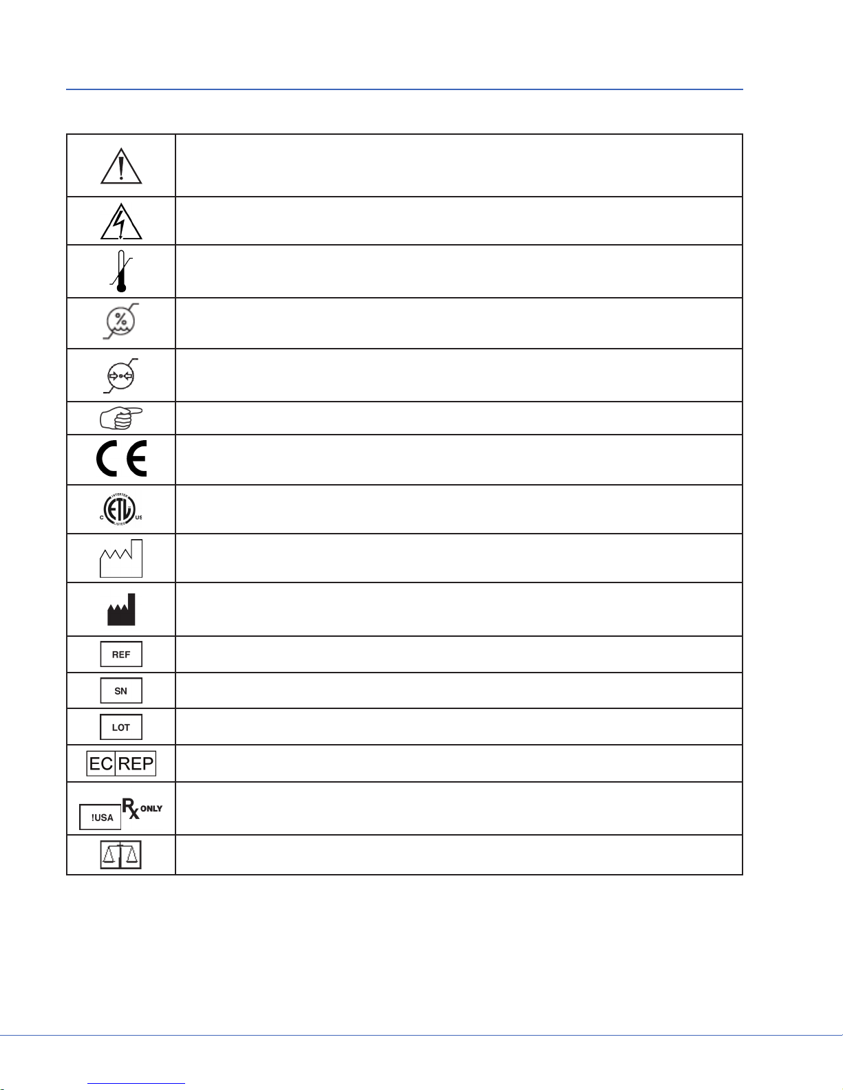
3. Product Symbol Denition
e following symbols may be found on the Stryker SwitchPoint Innity® 3 equipment:
An exclamation mark within a triangle is intended to alert the user to the presence
of important operating and maintenance (service) instructions in the literature accompanying the product.
A lightning bolt within a triangle indicates the presence of hazardous voltage. Refer
all service to authorized personnel.
Denotes temperature limits.
Denotes humidity limits.
Denotes pressure limits.
Denotes usage tips and useful information.
Denotes compliance to European Community Directive 93/42/EEC.
Denotes compliance to CSA Standard C22.2, 60601-1 - M90, AS 3200, IEC 60601-1,
UL 60601-1, EN 60601-1
Denotes the date the equipment was manufactured.
Denotes the manufacturer of the device.
Denotes product/part number.
Denotes product/serial number.
Denotes lot or batch number.
Denotes European Representative.
For U.S. audience only - Caution: Federal Law (USA) restricts this device to sale by
or on the order of a physician.
Denotes quantity.
6
Page 11
S
Denotes Class 1
Class 1 Equipment: equipment in which the protection against electric shock does
not rely on Basic Insulation only, but includes an additional safety precaution in
such a way that means are provided for the connection of Accessible Conductive
Parts to Protective (ground) Conductor in the xed wiring of the installation in such
a way that Accessible Conductive Parts cannot become Live in the event of a failure
of the Basic Insulation.
In accordance with European Community Directive 2002/96/EC on Waste Electrical and Electronic Equipment, this symbol indicates that the product must not be
disposed of as unsorted municipal waste but should be collected separately.
Note: e device does not contain any hazardous materials.
Legal regulations may include specications regarding the disposal of this product. We request that you contact Stryker when you plan to withdraw this device
from service for discard.
Denotes the device contains more than .002% cadmium.
Denotes the device contains more than .0005% mercury.
Denotes the device contains more than .004% lead.
LA
NSP
Limited Availability - Equipment may not be available in all regions.
Not Stryker Provided - Doc Stations must be provided by the customer outside the
U.S.
3.1 EMC Precautions
is device is considered medical electrical equipment and requires special precautions regarding
EMC and needs to be installed and put into service according to the information provided.
Portable and mobile RF communications equipment can aect this device's performance and must be
used in accordance with the following information.
WARNING e use of accessories, transducers, or cables other than those specied,
with the exception of those sold by Stryker, may result in increased emissions or decreased immunity of the equipment or system.
WARNING e equipment should not be used adjacent to or stacked with other equip-
ment. If stacking or adjacent placement is necessary, the equipment should
be observed to verify normal operation in the conguration in which it
will be used.
7
Page 12

S
4. Party Responsibilities
e responsibilities associated with planning and preparation for installation of Operating Room
Information System equipment will be shared between the Hospital, Contractor, and Stryker. ese
responsibilities are outlined below.
4.1 Hospital Responsibilities
1. Fill out the Ship and Installation Conrmation Form provided by the Stryker Representative.
is must be completed eight (8) weeks prior to the requested installation date.
2. e hospital must supply Stryker with up-to-date drawings in .dwg format (CAD) including but
not limited to:
• Room layout plans (current and proposed)
• Electrical services drawings
• Mechanical services drawings
• Elevation drawings
• Structural steel (support structure) drawings
• Ceiling drawings
3. e hospital must ensure Stryker is notied of all revisions and changes to drawings prior to and
during the scope of the project.
4. Accept delivery of Stryker equipment.
5. All Stryker-supplied equipment should be stored in a clean, temperature-controlled, dry environment prior to installation. Failure to comply may result in damage to the equipment, failure
of life support components, damage, and the.
6. On or before the installation start date, deliver Stryker crates and equipment to the proper
room(s).
7. Remove and dispose of the pallets, boxes, and trash during and aer the installation.
8. On the nal day of installation, sign Stryker Installation Acknowledgement Form. is form
must be signed before the room can be turned over to the hospital.
4.2 Contractor Responsibilities
1. Coordinate subcontractors.
2. Prior to the installation start date, provide all rough-in requirements as explained in this manual
and the Stryker rough-in drawings.
3. Prior to the installation start date, run all cabling, electrical, and data as instructed in this
manual and the Stryker Communications drawings.
4. Provide and pull all cables outside the operating room as specied in this manual.
5. Prior to the installation start date, connect all the required electrical circuits.
6. Prior to the installation start date, complete all work involving dust, paint, and ooring.
7. All non-Stryker equipment that is going to be connected to Stryker's ORIS equipment must be
installed prior to Stryker's installation start date.
8. All Stryker equipment that attaches to the building structure, such as Documentation Stations, Plasma/LCD display mounting brackets, and LCD projector mounting brackets, must be
mounted prior to Stryker's installation date. Exceptions are Stryker's booms and lights.
9. Prior to installation start date, any documentation station or cabinets that will house Stryker
8
Page 13

S
ORIS equipment must be fully assembled and connected to phone, data and power.
10. e proper Stryker cable kits must be pulled through any non-Stryker ceiling-mounted equipment prior to the Stryker installation date.
- International Only: If Stryker technicians are requested to pull cables through non-Stryker
ceiling-mounted equipment, the vendor of the equipment must be present to assist and provide instructions. e vendor will maintain responsibility for the nished, combined product.
11. All rooms must be reserved for Stryker Installation technicians only at all times during the
installation dates.
4.3 Stryker Responsibilities
1. Provide design assistance and recommendations.
2. Provide rough-in, cabling, electrical, and voice/data requirements listed in this manual.
3. Provide rough-in drawings.
4. Provide the hospital with a scope of work for Stryker's equipment installation.
5. Inventory all Stryker ORIS System components.
6. Pull all cables within the operating room. Hospital provides and pulls all cables outside of the
operating room, including auditoriums and conference rooms.
7. Terminate and test all low voltage cabling used to connect ORIS equipment with actual equipment or functionally equivalent signal generators.
8. Break down packaging material and gather all trash in a central location in the work area for
Hospital/Contractor removal.
9. Perform a nal review and "walk through" of the installation to ensure all equipment is functioning and all installation requirements have been met.
9
Page 14
S
5. iSuite Operating Room
e Stryker iSuite may consist of, but is not limited to, the following Stryker Communications equipment: SwitchPoint Innity, SwitchPoint Element, Documentation Station, Stryker Booms and Lights,
Speakers, PTZ Camera, and Wall Mounted Plasma/LCD. e operating room may also integrate with
an ORIS Video Network Hub and may contain a Fixed OR Status Camera. is section describes site
preparation requirements necessary for the installation phase of all Stryker ORIS equipment in the
operating room.
Note All electrical circuits called out in this manual are single Branch Circuits. For
example: 20 Amp/115 VAC within the US and 16/13 Amp 230 VAC in Europe or
equivalent per local electrical codes.
5.1 Documentation Station (Stryker Provided)
e Stryker-provided documentation station houses all the essential components of the iSuite. Prior
to receiving the documentation station the customer/Contractor must complete the Documentation
Station Order Conrmation Form (Provided by the Stryker Project Manager) and return to the PM at
least eight (8) weeks prior to the desired delivery date.
5.1.1 Receiving and Assembling the Documentation Station
Note Hospital/Contractor is responsible for receiving and assembling the documenta-
tion station prior to Stryker installation. e assembly may require up to four
people to complete the lis.
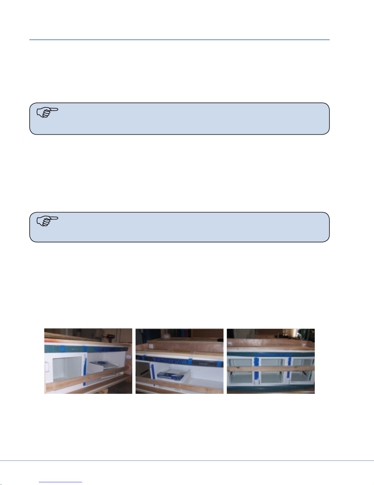
e documentation station will be delivered in three large wooden crates (top, middle, and base). is
is a large delivery and may require extra labor.
Dimensions of the Shipping Crates:
• 3-Bay: 40 x 80 x 36 40 x 80 x 42 40 x 80 x 48
• 2-Bay: 40 x 54 x 36 40 x 54 x 42 40 x 54 x 48
• 1-Bay: 40 x 60 x 48
Shipping crates:
10
Page 15
S
Upon delivery, uncrate the Stryker Documentation Station, transport to the appropriate location, and
assemble the three sections:
1. Roll the base section into place.
2. Li and level the base by adjusting the four leg levelers, found at each corner, with a screw
driver.
3. Li the middle section and set it on top of the base.
4. Center the middle section over the base and then push the middle section back until it stops.
5. Use the 2" #10 fasteners provided by the manufacturer to screw the middle section to the base
section. Use the pre-drilled holes at the top of each of the four corners of the base section to attach the two sections.
6. Repeat steps 2-5 to attach the top section to the middle section.
Note OSPHD anchoring details available from project manager upon request.
5.1.2 Additional Documentation Station Notes
• e right side of the documentation station is the standard side for the Innity router.
• Stryker provides the back boxes for all the outlets in the documentation station. All electrical
outlets and face plates must be provided and installed by the hospital/Contractor.
• Stryker does not engrave or label circuit IDs on faceplates.
• Use the duplex outlet, in the bottom le cabinet of the documentation station, for the Ethernet/
Comm connection plate. Stryker only supplies the metal back box for this outlet.
• e bottom section is on casters and will easily roll into place. is allows for the electrician to
easily run power to the documentation station before rolling into place.
• ere will be a 1" gap between the base of the cabinet and the nished oor. Stryker recommends coving/ashing up the oor for cleaning purposes.
• Once in place, Stryker recommends sealing or caulking the sides of the documentation station
to the wall.
• e top of the documentation station is a at surface and Stryker does not provide a sot.
• Stryker recommends one circuit to feed the top and middle outlets, one circuit to feed the Innity side of the cabinet, and one circuit for the Power Supply box side of the cabinet.
11
Page 16
S
5.1.3 Installing the Documentation Station
Note All conduits should be provided with pull strings and should have minimum
bends or curves. All conduits have a maximum length of 45'. Conduits must have
insulated bushings on all open ends.
Install two (2) Ethernet connections for the SORN (Stryker's Remote Device Management System) and
SDC, respectively. A telephone connection may be desired for a nurse’s phone. Similarly, additional
Ethernet connections may be desired for a Nurses Computer and/or PACS Computer. If local Video
Conferencing via a CODEC is installed, an additional Ethernet connection is required. All additional
telephone/Ethernet connections will be specied by the Hospital.
ONE-BAY DOCUMENTATION STATION (DOC1)
US
Dimensions 25.5"W x 90"H x 30.2"D
Power ree (3) – 20 Amp circuits
• One (1) circuit for quad outlet in lower section.
• One (1) circuit for 2 duplex outlets in lower section.
• One (1) circuit for quad outlet in upper section.
• All documentation station circuits require critical power.
Data Per listed equipment
Backbox Per listed equipment
TWO-BAY DOCUMENTATION STATION (DOC2)
US
Dimensions 48"W x 90"H x 37"D
Power Recommend Six (6) - 20 amp circuits:
• One (1) circuit for quad outlet in lower section behind video router.
• One (1) circuit for quad outlet in lower section behind the light power supply box (if required).
• One (1) circuit for duplex outlet in lower section under touch panel.
• One (1) circuit for quad outlet in middle section behind digital capture device.
• One (1) circuit for quad outlet in upper le section (if required).
• One (1) circuit for quad outlet in upper right section (if required).
• All documentation station circuits require critical power.
Data Per listed equipment
Backbox Per listed equipment
12
Page 17
S
THREE-BAY DOCUMENTATION STATION (DOC3)
US
Dimensions 72"W x 90"H x 37"D
Power Recommend seven (7) - 20 amp circuits
• One (1) circuit for quad outlet in lower section behind video router.
• One (1) circuit for quad outlet in lower section behind light PSB (if required).
• One (1) circuit for duplex outlet in lower section under touch panel.
• One (1) circuit for quad outlet in middle section behind digital capture
device.
• One (1) circuit for quad outlet in upper le section (if required).
• One (1) circuit for quad outlet in upper middle section (if required).
• One (1) circuit for quad outlet in upper right section (if required).
• All documentation station circuits require critical power.
Data Per listed equipment
Backbox Per listed equipment
13
Page 18

S
29.1"
90.0"
66.0"
41.8"
28.0"
21.9"
7.9"
18.0"
15.0"
23.5"
82.8"
28.6"
24.0" 11.4"
12.1"
18.1"
24.0"
10.5"
14.4"
8.8"
4.5"
4.4"
19.1"
19.3"
16.4"16.5"
14.0"
(5X) ELECTRICAL
QUAD
(2X) ELECTRICAL
DUPLEX
CUT-OUT
FLEX
CONDUIT
4"(80mm) x 4"(80mm)
ELECTRICAL
J-BOX
4"(80mm) x 4"(80mm)
ELECTRICAL
J-BOX
18" x 18"
SWITCHPOINT
INFINITY J-BOX
J-BOX (FOR STRYKER
LIGHTS ONLY)
4"(80mm) x 4"(80mm)
ELECTRICAL
J-BOX
4"(80mm) x 4"(80mm)
ELECTRICAL
J-BOX
FLEX
CONDUIT
WALL
ELECTRICAL
DUPLEX
(5X) ELECTRICAL
QUAD
1. THIS DRAWING IS FOR REFERENCE OF CUT-OUT LOCATIONS ONLY. IT IS NOT INTENDED FOR
MANUFACTURING USE.
2. DRAWING DISPLAYS FRONT VIEW OF DOCUMENTATION STATION WITH DOORS OMITTED.
3. PROVIDE AND INSTALL SIX (6) ELECTRICAL QUAD OUTLETS AND SIX (6) DUAL GANG FACE PLATES AS
WELL AS TWO (2) ELECTRICAL DUPLEX OUTLETS WITH TWO (2) SINGLE GANG FACE PLATES INTO THE
ELECTRICAL JUNCTION BOXES PROVIDED.
4. INSTALL AND CONNECT FLUORESCENT LIGHTING FIXTURE IF PROVIDED.
5. PROVIDE AND CONNECT 20 AMP CIRCUITS FOR THE STRYKER DOCUMENTATION STATION FOR EACH
QUAD PLEX OUTLET: ONE (1) 20 AMP CIRCUIT FOR EACH OF THE TWO (2) DUPLEX OUTLETS IN THE
DOCUMENTATION STATION WITH ONE (1) CIRCUIT ALSO POWERING THE FLUORESCENT LIGHTING. IF
INSTALLING STRYKER VISUM LIGHTS, ONE (1) 20 AMP CIRCUIT IS REQUIRED FOR EACH LIGHT POWER
SUPPLY BOX (REFER TO VISUM PRE-INSTALLATION GUIDE FOR LOCATION OF POWER SUPPLY BOX).
POWER SHOULD BE CONNECTED USING CONDUIT FROM THE WALL TO FACILITATE FUTURE ACCESS TO
THE CABLE CHASE IN THE BACK OF THE DOCUMENTATION STATION. ALL STRYKER DOCUMENTATION
STATION CIRCUITS SHOULD BE ON CRITICAL POWER.
SCALE: 1" = 1'
CUTOUT
5X 4.25 X 4.25 CUTOUT
(ELECTRICAL QUAD)
4X 2.5 DIA.
(GROMMET)
SHEET:
NOTES: (UNLESS OTHERWISE SPECIFIED)
1. EQUIPMENT LIST:
Figure 5.4 - Two-Bay Documentation Station
LA
14
Page 19

5. PROVIDE AND CONNECT 20 AMP CIRCUITS FOR THE STRYKER DOCUMENTATION STATION FOR EACH
QUAD PLEX OUTLET: ONE (1) 20 AMP CIRCUIT FOR EACH OF THE TWO (2) DUPLEX OUTLETS IN THE
DOCUMENTATION STATION WITH ONE (1) CIRCUIT ALSO POWERING THE FLUORESCENT LIGHTING. IF
INSTALLING STRYKER VISUM LIGHTS, ONE (1) 20 AMP CIRCUIT IS REQUIRED FOR EACH LIGHT POWER
SUPPLY BOX (REFER TO VISUM PRE-INSTALLATION GUIDE FOR LOCATION OF POWER SUPPLY BOX).
POWER SHOULD BE CONNECTED USING CONDUIT FROM THE WALL TO FACILITATE FUTURE ACCESS TO
THE CABLE CHASE IN THE BACK OF THE DOCUMENTATION STATION. ALL STRYKER DOCUMENTATION
STATION CIRCUITS SHOULD BE ON CRITICAL POWER.
www.stryker.com
A
FLOWER MOUND, TEXAS 75028
1410 LAKESIDE PARKWAY, SUITE 100
PHONE: (877) 789-8106
FAX: (972) 410-7001
SHEET:
B
C
02
02
14.0 X 14.0 CUTOUT
23.8"
16.2"
HARD-PIPED
(BEHIND SHELVES) IF
4.8"7.4"
90.0"
78.5"
6X 4.25 X 4.25 CUTOUT
(ELECTRICAL QUAD)
3X 66.0"
41.8"
28.0"
21.9"
14.0"
S
7.8"
14.0 X 20.0 CUTOUT
21.7"
1.4"
11.2"
5.1"
28.5"
16.3"
4"(80mm) x 4"(80mm)
WALL
4"(80mm) x 4"(80mm)
ELECTRICAL
FLEX
J-BOX
ELECTRICAL
J-BOX
FLEX
6X 2.5 DIA.
CONDUIT
CONDUIT
(GROMMET)
CUTOUT
(DATA / AV)
2.25 X 4.13 CUTOUT
QUAD
(6X) ELECTRICAL
(2X) ELECTRICAL
DUPLEX
ELECTRICAL
DUPLEX
CUT-OUT
18.0"
29.1"
4"(80mm) x 4"(80mm)
J-BOX
ELECTRICAL
15"
SWITCHPOINT
INFINITY J-BOX
18" x 18"
10.0"
Figure 5.5 - ree-Bay Documentation Station
MANUFACTURING USE.
1. THIS DRAWING IS FOR REFERENCE OF CUT-OUT LOCATIONS ONLY. IT IS NOT INTENDED FOR
NOTES: (UNLESS OTHERWISE SPECIFIED)
1. EQUIPMENT LIST:
15
WELL AS TWO (2) ELECTRICAL DUPLEX OUTLETS WITH TWO (2) SINGLE GANG FACE PLATES INTO THE
ELECTRICAL JUNCTION BOXES PROVIDED.
2. DRAWING DISPLAYS FRONT VIEW OF DOCUMENTATION STATION WITH DOORS OMITTED.
4. INSTALL AND CONNECT FLUORESCENT LIGHTING FIXTURE IF PROVIDED.
3. PROVIDE AND INSTALL SIX (6) ELECTRICAL QUAD OUTLETS AND SIX (6) DUAL GANG FACE PLATES AS
DOC STATION CENTER POINT
QUAD
(6X) ELECTRICAL
DATA / AV
CONNECTION
CUT-OUT
J-BOX
ELECTRICAL
4"(80mm) x 4"(80mm)
J-BOX (FOR STRYKER
6"(150mm) X 6"(150mm)
20"
6"
LIGHTS ONLY)
Page 20

S
5.2 Documentation Station (Hospital Provided)
Note All conduits should be provided with pullstrings and have minimum bends or
curves. All conduits have a maximum length of 45' (13.7m). Conduits must have
insulated bushings on all open ends.
e hospital-provided documentation station must allow for the physical dimensions and power requirements for all equipment it is to hold.
CUSTOMER SUPPLIED DOCUMENTATION STATION (DOC4)
Power Recommend four (4) - 20 amp circuits
• One (1) circuit for quad outlet behind video router.
• One (1) circuit for quad outlet behind light PSB (if required).
• One (1) circuit for duplex outlet under touch panel.
• One (1) circuit for quad outlet behind digital capture device.
• All documentation station circuits require critical power.
Space Requirements Doc station must allow for a minimum 2" cable passage between all compo-
nents housed inside.
• Section housing video router must have an interior dimension of at
least 27.5"W x 31"H x 29"D.
• Section housing video router must be vented.
• Doc station must allow for direct access to backboxes per requirements
listed below.
Data Per listed equipment
Backbox Per listed equipment
Install two (2) Ethernet connections for the SORN (Stryker's Remote Device Management System) and
SDC, respectively. A telephone connection may be desired for a nurse's phone. Similarly, additional
Ethernet connections may be desired for a Nurses Computer and/or PACS Computer. If local Video
Conferencing via a CODEC is installed, an additional Ethernet connection is required. All additional
telephone/Ethernet connections will be specied by the Hospital.
5.3 Documentation Station Equipment Requirements
SWITCHPOINT INFINITY 3 (A1)
Dimensions • Media Router: 20.6"W x 24"H x 17"D
• Control Section: 12.5"W x 2.6"H x 17"D
• Total Space Required: 27.5"W x 31"H x 29"D
Data One (1) Ethernet connection
Back Box • One (1) 18"W x 18"H x 4"D (or larger) junction box ush mounted.
• Set bottom of box 9" above nished oor.
• Terminate all integration conduits to this junction box.
16
Page 21

S
SPI3-LITE (A4)
Dimensions • Media Router: 16.4"W x 15.3"H x 17.4"D
• Control Section: 12.5"W x 2.6"H x 17"D
• Total Space Required: 27.5"W x 31"H x 29"D
Data One (1) Ethernet connection
Back Box • One (1) 18"W x 18"H x 4"D (or larger) junction box ush mounted.
• Set bottom of box 9" above nished oor.
• Terminate all integration conduits to this junction box.
SPI3 TOUCH PANEL, 22" (B1)
Dimensions 20.3"W x 15.8"H x 13.5"D with stand
SPI3 TOUCH PANEL, 19" (C)
Dimensions 17.7"W x 15"H x 11.8"D with stand
SWITCHPOINT INFINITY 2 (A2)
Dimensions • Router: 21.0"W x 24.0"H x 22.3"D
• Total space required: 27.5"W x 31"H x 29"D
Data One (1) Ethernet connection
Back Box • One (1) 18"W x 18"H x 4"D (or larger) junction box ush mounted.
• Set bottom of box 9" above nished oor.
• Terminate all integration conduits to this junction box.
SPI2 TOUCH PANEL, 19" (B2)
Dimensions 16.9"W x 15.5"H x 8.2"D with stand
SWITCHPOINT ELEMENT (A3)
Dimensions • Video Router: 12.5"W x 10"H x 15"D
• Control System: 12.5"W x 2"H x 15"D
• Total Space Required: 27.5"W x 31"H x 29"D
Data One (1) Ethernet connection
Back Box • One (1) 18"W x 18"H x 4"D (or larger) junction box ush mounted.
• Set bottom of box 9" above nished oor.
• Terminate all integration conduits to this junction box.
SPE TOUCH PANEL, 12" (B3)
Dimensions 11.9"W x 11.3"H x 6.6"D with stand
SUITESTREAM CODEC (D)
Dimensions 12.7"W x 2.6"H x 17.3"D
17
Page 22

S
Data • Two (2) Ethernet connections
• Please refer to Stryker ConnectSuite Pre-Install document,
SOP0304.08 for specic network requirements..
SDC ULTRA (F)
Dimensions 12.5"W x 7"H x 16.2"D
Data One (1) Ethernet connection
SDP1000 PRINTER (H)
Dimensions 12.5"W x 8.2"H x 16.7"D
SIDNE (I)
Dimensions 12.6"W X 4.5"H X 16.2"D
WISE TRANSMITTER (J)
Dimensions 12.5"W X 3.3"H X 15.2"D
NAVIGATION PC (K)
Dimensions 17"W X 20"H X 24"D
Data One (1) Ethernet connection
HD CODEC (L)
Dimensions 5.1"W X 13.9"H X 11"D
Data • One (1) Ethernet connection
• Please consult project manager if ISDN is utilized
SD CODEC (L1)
Dimensions 19.5"W X 2"H X 12"D
Data One (1) Ethernet connection
Please consult project manager if ISDN is utilized
WIRELESS MICROPHONE RECEIVER (M)
Dimensions 8.3"W X 1.93"H X 7.2"D
VISUM HALOGEN POWER SUPPLY BOX (N)
Dimensions • PSB: 17.8"W X 6"H X 15.8"D
• Total Space Required: 20"W X 9"H X 21"D
Back Box • One (1) 6"W x 6"H x 4"D (or larger) junction box ush mounted.
• Set bottom of box 14" above nished oor.
• Terminate all surgical light conduits to this junction box
18
Page 23

S
VISUM LED POWER SUPPLY BOX (N1)
Dimensions • PSB: 12.5"W X 7"H X 15.5"D
• Total Space Required: 20"W X 9"H X 21"D
Back Box • One (1) 6"W x 6"H x 4"D (or larger) junction box ush mounted.
• Set bottom of box 14" above nished oor.
• Terminate all surgical light conduits to this junction box
5.4 iSuite Equipment Integration Notes
Note All conduit runs include insulated bushings and pull strings.
Note Conduit runs cannot exceed 50' from end-to-end. Do not exceed four (4) 90 de-
gree bends.
5.4.1 Wall Mounted 46" or 55" LCD Monitor or 42" TouchPanel
Conduit One (1) 1 1/4" conduit
Back Box • 4"W X 4"H junction box with single-gang mud ring
• Mounted directly above the top of the mounting bracket.
Power One (1) standard duplex outlet mounted adjacent to junction box
Structural • Customer/Contractor to mount Stryker provided bracket to the wall in the de-
sired location with proper reinforcement to support the monitor prior to Stryker
installation.
• Stryker Project Manager will provide mounting specications.
ITEM-ITEM QTY SIZE
WMM – A
5.4.2 Wall/Ceiling Mounted Room Status Camera (WRC, CRC)
1
1 1/4"
LA
Conduit One (1) ¾" conduit terminated at nearest corridor cable tray
Back Box • 4"W x 4"H junction box with single-gang mud ring
• Flush mounted at 12" below nished ceiling (wall mounted only)
Power None
Cabling • One (1) power cable and one (1) video cable
• One (1) Belden 8723 / 88723 (maximum 1000')
• One (1) Belden 8241 / 88241 (maximum 1000')
• Cables require 15' service loop at both ends
Note All Status System cabling must be provided and pulled by the Hospital/Contrac-
tor prior to Stryker Installation.
19
Page 24

S
ITEM-ITEM QTY SIZE
WRC/CRC – *
5.4.3 Wall Plates
Conduit One (1) ½" conduit
Back Box • 4"W x 4"H junction box with single-gang mud ring
Power None required, but should be located next to outlet
ITEM-ITEM QTY SIZE
Copper DVI (CDP) – A
VGA/S-Video/BNC (TRP) - A
Pass-rough (PTP) - A
Fiber Optical DVI - A
1
¾"
• 4"W x 4"H junction box with dual-gang mud ring (Fiber optical DVI only)
• Mounted 18" above nished oor.
1
1 ½"
1 1"
1 1"
1 1"
5.4.4 Observation Room Touch Panel, Microphone and Speaker (OBS)
LA
Conduit One (1) 1" conduit terminated
Cabling For runs over 50', Hospital/Contractor provides the following:
• Two (2) Belden 8723 / 88723 (maximum 1000')
• One (1) CAT6 cable (maximum 328')
• Cables require 15' service loop at both ends
• Cabling provided and pulled by Hospital/Contractor before Stryker installation
Back Box • 4"W x 4"H junction box with single-gang mud ring
• Mounted within 18" of touch panel location
Power One (1) standard outlet within 18" of touch panel location
ITEM-ITEM QTY SIZE
OBS – A
1
1"
5.4.5 Cable Run to Video Network Hub (HRN)
Conduit One (1) 2" conduit terminated at nearest corridor cable tray.
Cabling • Four (4) Belden 8241/88241 or equivalent (maximum 1000' - consult Project Man-
ager for runs over 1000')
• Two (2) Belden 8723 / 88723 or equivalent (maximum 1000' - consult Project Manager for runs over 1000')
• One (1) CAT6 cable (maximum 328' - consult Project Manager for runs over 328'))
• Cables require 15' service loop at both ends
• Hub cabling provided and pulled by Hospital/Contractor before Stryker installation
ITEM-ITEM QTY SIZE
HRN – *
20
1
2"
Page 25

S
5.4.6 Equipment Boom Cable Kit (Brand) (EQB)
Cabling All cabinets within the boom must be pulled by Hospital/Contractor if not already
pulled by boom manufacturer
Conduit Terminated within 18" of the center of the ceiling mount
Power Per boom manufacturer specications
Plumbing Per boom manufacturer specications
Access Panel One (1) 24" x 24" access panel adjacent to suspension
Structural Per boom manufacturer specications
ITEM-ITEM QTY SIZE
EQB – A
5.4.7 Anesthesia Boom Cable Kit (Brand) (ANB)
Cabling All cables within the boom must be pulled by Hospital/Contractor if not already
Conduit Terminated within 18" of the center of the ceiling mount
Power Per boom manufacturer specications
Plumbing Per boom manufacturer specications
2
pulled by boom manufacturer
2"
Access Panel One (1) 24" x 24" access panel adjacent to suspension
Structural Per boom manufacturer specications
ITEM-ITEM QTY SIZE
ANB – A
1
2"
5.4.8 Navigation Arm (NAM)
Conduit Terminated to 10" x 10" x 4" NEMA type 1 box within 18" of the center of the ceiling
mount.
Power No additional power required.
Access Panel One (1) 24" x 24" access panel adjacent to suspension
Structural • Optimal location for center of Navigation camera is 47" above nished oor.
• Stryker preinstall plate is installed per customer structural engineer specs at 4"
above nished ceiling.
• A 21" circular hole centered on Stryker preinstall plate in the nished ceiling is
required for installation. A 24" diameter ceiling cover conceals hole aer suspension is installed.
• e Contractor/electrician to hardwire Stryker electrical whip during Stryker
installation.
• Load location: X=31", Y=45"
• Maximum deection: 1 degree
ITEM-ITEM QTY SIZE
NAM – A
21
1
2"
Page 26

S
5.4.9 Stryker Single Flat Panel Arm Cable Kit
Conduit One (1) 2" (50mm) conduit terminated with insulated bushings within 18" (450mm)
of the center of the ceiling mount. is conduit must be accessible from the access
panel and terminated in a horizontal orientation. Pull strings should be provided.
Power One (1) - 20 AMP circuit located at junction box within 18" of center of Stryker pre-
install plate. Hospital/Contractor should hardwire during installation.
Access Panel One (1) 24" x 24" access panel adjacent to suspension
5.4.10 Stryker Dual Flat Panel Arm Cable
Conduit One (1) 2" (50mm) conduit terminated with insulated bushings within 18" (450mm)
of the center of the ceiling mount. is conduit must be accessible from the access
panel and terminated in a horizontal orientation. Pull strings should be provided.
Power One (1) - 20 AMP circuit located at junction box within 18" of center of Stryker pre-
install plate. Hospital/Contractor should hardwire during installation.
Access Panel One (1) 24" x 24" (610mm x 610mm) access panel adjacent to suspension
5.4.11 Single Flat Panel Arm Cable Kit (Non-Stryker Flat Panel Arm) (NAM)
Conduit Two (2) 2" (50mm) conduit terminated with insulated bushings within 18" (450mm)
of the center of the ceiling mount. is conduit must be accessible from the access
panel and terminated in a horizontal orientation. Pull strings should be provided.
Power Two (2) - 20 AMP circuit located at junction box within 18" of center of Stryker pre-
install plate. Hospital/Contractor should hardwire during installation.
Access Panel One (1) 24" x 24" (610mm x 610mm) access panel adjacent to suspension
5.4.12 Dual Flat Panel Arm Cable Kit (Non-Stryker Flat Panel Arm)
Conduit Two (2) 2" (50mm) conduit terminated with insulated bushings within 18" (450mm)
of the center of the ceiling mount. is conduit must be accessible from the access
panel and terminated in a horizontal orientation. Pull strings should be provided.
Power Two (2) - 20 AMP circuit located at junction box within 18" of center of Stryker pre-
install plate. Hospital/Contractor should hardwire during installation.
Access Panel One (1) 24" x 24" (610mm x 610mm) access panel adjacent to suspension
22
Page 27

S
6. Innity Based Conference System (IBC) Rooms
LA
Note All cabling must be provided and pulled by Hospital/Contractor prior to Stryker's
arrival.
IBC's are most oen installed in auditoriums, classrooms, and large conference rooms. e IBC can be
installed in a variety of places. e control system can either sit in a closet or in the back of the room.
A podium is recommend to accommodate the IBC Touch Panel and cable runs to the control system.
6.1 SPI3 Customer Supplied Casework (SCW)
Data Per listed equipment
Back Box Per listed equipment
Power Recommended two (2) - 20 amp circuits:
• One (1) circuit for quad outlet behind video router
• One (1) circuit for quad outlet behind support equipment
Space
Requirements
• Casework must allow for a minimum 2" cable passage between all components housed inside.
• Section housing video router must have an interior dimension of at least
27.5"W X 31"H X 29"D.
• Section housing video router must be vented.
• Must allow for direct access to backboxes per requirements listed below.
6.2 IBC Unit with Tower (ICW1)
LA
Dimensions 27.5"W X 65"H X 30"D
Data One (1) Ethernet connection
Back Box • One(1) 18"W X 18"H X 4"D (minimum) junction box ush mounted.
• Set bottom of the box 9" above nished oor within the footprint of the tower.
• Terminate all integration conduits to this junction box.
• Hospital/Contractors will provide and pull all cables.
Power One (1) - 20 AMP circuit for quad outlet behind the tower.
6.3 IBC Unit with Stryker Credenza (ICW2)
LA
Data One (1) Ethernet connection
Back Box • One(1) 18"W X 18"H X 4"D (minimum) junction box ush mounted.
• Set bottom of the box 9" above nished oor within the foot print of the tower.
• Terminate all integration conduits to this junction box.
• Hospital/Contractor will provide and pull all cables.
Power One (1) - 20 amp circuit for quad outlet behind the tower.
Note Customer/Contractor responsible for receiving and installing Credenza prior to
Stryker installation.
23
Page 28

S
6.4 IBC with Customer Supplied Casework (ICW3)
LA
Data Per listed equipment
Back Box • One(1) 18"W X 18"H X 4"D (minimum) junction box ush mounted.
• Set bottom of the box 9" above nished oor within the foot print of the tower.
• Terminate all integration conduits to this junction box.
• Hospital/Contractor will provide and pull all cables.
Power • One (1) - 20 amp circuit for outlets behind video router.
• One (1) - 20 amp circuit for quad outlet behind casework.
Space
Requirements
• Must allow for a minimum 2" cable passage between all components housed
inside.
• Section housing video router must have an interior dimension of at least
27.5"W X 31"H X 29"D.
• Section housing the video router must be vented.
• Must allow for direct access to backboxes per requirements listed below.
Note Customer/Contractor responsible for installation of casework prior to Stryker
installation.
6.5 Casework Equipment
6.5.1 SwitchPoint Innity 2 (A2)
Dimensions • Router 19.5"W X 28.5"H X 23"D
• Total Space Required: 27.5"W X 31"H X 29"D
Data One (1) Ethernet connection
Back Box • One(1) 18"W X 18"H X 4"D (minimum) junction box ush mounted.
• Set bottom of the box 9" above nished oor.
• Terminate all integration conduits to this junction box.
Power One (1) standard outlet within 3'.
6.5.2 SPI2 Touch Panel, 19" (B2)
Dimensions 16.9"W X 15.5"H X 8.2"D with stand
Power One (1) standard outlet within 3'
6.5.3 Wireless Microphone Receiver (M)
Dimensions 8.3"W X 1.93"H X 7.2"D
Power One (1) standard outlet within 3'
LA
24
Page 29

6.5.4 SD CODEC (L1)
Dimensions 19.5"W X 2"H X 12"D
Data • One (1) Ethernet connection
• Please consult Project Manager if ISDN is utilized.
Power One (1) standard outlet within 3'
S
6.6 IBC Podium with Touch Panel
LA
Note Customer/Contractor responsible for installation of podium prior to Stryker
installation.
Dimensions 32"W X 46"H X 24.3"D
Cabling • Cables provided by the Hospital/Contractor for runs over 50'.
• Cables pulled by the Hospital/Contractor.
• Leave a 15' (4.5m) service loop at each end for terminations.
• Cable Specications: Cables may vary depending on conference room congurations. Please consult Project Manager for site specic requirements:
• Touch Panel:
º One (1) Belden 8723 or equivalent (maximum 1000')
º One (1) Extron MHR5 or equivalent (maximum 150')
• Laptop Connection:
º One (1) Belden 8723 or equivalent (maximum 1000')
º One (1) Extron MHR5 or equivalent (maximum 150')
• PC Connection:
º One (1) Belden 8723 or equivalent (maximum 1000')
º One (1) Extron MHR5 or equivalent (maximum 150')
• Podium Microphone
º One (1) Belden 8723 or equivalent (maximum 1000')
• Network
º Two (2) CAT6 cables (maximum 328')
Conduit Two (2) 2" conduits
Back Box • 12"W X 12"H junction box
• Flush mounted in the oor under the podium
Power • One (1) standard outlet
• Flush mounted in the oor beneath podium adjacent or within 12" X 12" junction box
ITEM-ITEM QTY SIZE
IPD – ICW
25
2
2"
Page 30

S
7. Level Systems Room
Note All cabling must be provided and pulled by Hospital/Contractor prior to Stryker's
arrival.
Level System's are most oen installed in integrated doctor's oces, small conference rooms, and
pathology or nuclear medicine labs. is control system is placed in a cabinet next to or in the room's
cabinetry or desk. Cable passage must be allowed to the junction box for all equipment placed on the
desk or in the cabinetry.
7.1 Customer Supplied Casework (CSC)
Data Per listed equipment
Back Box Per listed equipment
Power One (1) - 20 amo circuit for outlets behind video router
Space
Requirements
• Must allow for a minimum 2" cable passage between all components housed
inside.
• Section housing video router must have an interior dimension of at least 21"W
X 16"H X 22"D
• Section housing router must be vented.
• Must allow for direct access to back boxes per requirements listed below.
Note Customer/Contractor responsible for installation of casework prior to Stryker
installation.
7.2 Casework Equipment
7.2.1 Level One System (S1)
Dimensions 20.5"W X 8.5"H X 16"D
Data None
Back Box • One (1) 6"W X 6"H X 4"D (minimum) junction box ush mounted at
same height as Level System
• Terminate all integration conduits to this junction box
Power One (1) duplex outlet next to junction box
7.2.2 Level Two System (S2)
Dimensions 20.5"W X 14"H X 19"D
Data None
Back Box • One(1) 12"W X 12"H X 4"D (minimum) junction box ush mounted at
same height as Level System
• Terminate all integration conduits to this junction box
Power One (1) duplex outlet next to junction box
LA
LA
26
Page 31

7.2.3 Level System Touch Panel (T)
Dimensions • Touch Panel: 11.9"W X 11.3"H X 6.6"D
• Touch Panel Interface: 19"W X 2"H X 11"D
Power One (1) duplex outlet
7.3 Remote Level System Touch Panel (LTP)
Dimensions • Touch Panel: 11.9"W X 11.3"H X 6.6"D
• Touch Panel Interface: 19"W X 2"H X 11"D
Cabling • Cables provided by the Hospital/Contractor for runs over 50'
• Cables pulled by the Hospital/Contractor
• Leave a 15' (4.5m) services loop at each end for terminations
• Cable Specications:
º ree (3) Belden 8723 or equivalent (maximum 1000')
º One (1) Belden 8241 or equivalent (maximum 1000')
Conduit One (1) 1" conduit
Back Box • 4"W X 4"H junction box with single-gang mud ring
• Mounted within 18" of touch panel location
Power One (1) standard outlet within 18" of touch panel location
S
ITEM-ITEM QTY SIZE
LTP – S
1
1"
27
Page 32

S
8. Equipment Integration Notes
8.1 Wall Mounted 46" or 55" LCD Monitor, or 42" Touch Panel
Dimensions • 46" Monitor: 41.6" X 24.0" X 4.1" (1055.4 x 608.6 x 103mm)
• 55" Monitor: 51.9" X 30.5" X 4.7" (1317.8 x 775.8 x 118.9mm)
• 42" Touch Panel: 40.2" X 24.1" X 5.2" (1020 x 132 x 613mm)
Back Box • 4"W X 4"H junction box with single-gang mud ring
• Mounted directly above the top of the mounting bracket
Power One (1) standard duplex outlet mounted adjacent to the junction box
Structural • Customer/Contractor to mount Stryker provided bracket to the wall in the
desired location with proper reinforcement to support the monitor
• Stryker Project Manager will provide mounting specications
Cabling • Cables provided by the Hospital/Contractor for runs over 50'
• Cables pulled by the Hospital/Contractor
• Leave a 15' (4.5m) service loop at each end for terminations
LA
8.1.1 SPI3 Cable Specications
• One (1) Belden 8723 or equivalent (maximum 1000')
• One (1) - Four (4) strand, multimode ber optic cable
º Quantity of bers within cable - four (4)
º LC Connectors on each end
º 50/125 Micron
ITEM-ITEM QTY SIZE
3WM – A
1
1 1/4"
8.1.2 SPI3 42” Touch Panel Cable Specications
• One (1) Extron MHR5 or equivalent (maximum 150')
• One (1) Cat5, Cat5E, or Cat6 network cable (maximum 150')
ITEM-ITEM QTY SIZE
3WM – A
8.1.3 IBC Cable Specications
• One (1) Belden 8723 or equivalent (maximum 1000')
• One (1) Extron MHR2 or equivalent (maximum 150')
• One (1) Extron MHR5 or equivalent (maximum 150')
ITEM-ITEM QTY SIZE
IWM – ICW
1
1
1 1/4"
LA
1 1/4"
28
Page 33

S
8.1.4 Level System Cable Specications
• One (1) Belden 8723 or equivalent (maximum 1000')
• One (1) Belden 8241 or equivalent (maximum 1000')
ITEM-ITEM QTY SIZE
LWM – S
8.2 Motorized Projection Screen (MPS)
Conduit One (1) 3/4" conduit
Back Box Junction box is located in le end cap of assembly
Power • Customer/Contractor to hardwire to standard electrical circuit prior to Stryker
Structural • Customer/Contractor to mount Stryker provided bracket to the wall in the
1
• Installation instructions included with assembly
• Stryker Project Manager will provide mounting specications
1"
installation
desired location with proper reinforcement to support the monitor
8.3 Motorized Projection Screen Wall Switch (SWS)
Conduit One (1) 3/4" conduit
Back Box • 4"W X 4"H junction box with single-gang mud ring
• Flush mounted at standard light switch height
Power • Customer/Contractor to hardwire to standard electrical circuit prior to Stryker
installation
• Installation instructions included with assembly
ITEM-ITEM QTY SIZE
MPS – SWS
1
3/4"
8.4 Ceiling Mounted Projector
Cabling • Cables provided by the Hospital/Contractor for runs over 50'
• Cables pulled by the Hospital/Contractor
• Leave a 15' service loop at each end for terminations
Back Box • 4"W X 4"H junction box with single-gang mud ring
• Mounted 12" (minimum) behind projector mounting bracket
Power One (1) standard duplex outlet ceiling mounted adjacent to junction box
Structural • Customer/Contractor to mount Stryker provided bracket to the ceiling in the
designated location with proper reinforcement to support the projector prior
to Stryker installation
• Stryker Project Manager will provide mounting specications
8.4.1 SPI3 Cable Specications
• One (1) Belden 8723 or equivalent (maximum 1000')
29
Page 34

S
• One (1) Extron MHR5 or equivalent (maximum 150')
• One (1) - Four (4) strand, multimode ber optic cable
º Quantity of bers within cable - Four (4)
º LC Connectors on each end
º 50/125 Micron
ITEM-ITEM QTY SIZE
3PR – A
8.4.2 IBC Cable Specications
• One (1) Belden 8723 or equivalent (maximum 1000')
• One (1) Extron MHR5 or equivalent (maximum 150')
• One (1) Extron MHR5 or equivalent (maximum 150')
ITEM-ITEM QTY SIZE
IPR – ICW
8.4.3 Level System Cable Specications
1
1
1 1/4"
1 1/4"
• One (1) Belden 8723 or equivalent (maximum 1000')
• One (1) Belden 8241 or equivalent (maximum 1000')
ITEM-ITEM QTY SIZE
LPR – S
1
1"
8.5 Bracket Mounted Wall /Ceiling Speaker
Conduit One (1) 3/4" conduit
Cabling • Cables provided by the Hospital/Contractor for runs over 50'
• Cables pulled by the Hospital/Contractor
• Leave a 15' (4.5m) service loop at each end for terminations
• Cable Specications:
º One (1) Belden 8723 or equivalent (maximum 1000')
Back Box • 4"W X 4"H junction box with single-gang mud ring.
• Mounted 12" (minimum) behind projector mounting bracket (wall mounted
only)
• Flush Mounted in ceiling (ceiling mounted only)
Power None
ITEM-ITEM QTY SIZE
3WS/3CS – A (SPI3)
IWS/ICS – ICW (IBC)
30
1
1
3/4"
3/4"
Page 35

S
8.6 Flush Mounted Rectangular Wall/Ceiling Speaker
Conduit One (1) 3/4" conduit terminated 2" above speaker cutout
Cabling • Cables provided by the Hospital/Contractor for runs over 50'
• Cables pulled by the Hospital/Contractor
• Leave a 15' (4.5m) service loop at each end for terminations
• Cable Specications:
º One (1) Belden 8723 or equivalent (maximum 1000')
Power None
Structural • Customer/Contractor to cut one 7 1/4"W X 10 3/4"L (template supplied with
speaker) in the wall at each speaker mounting location. Fits into a standard 2"
X 4" wall (wall mounted only)
• Minimum 4" ceiling clearance (ceiling mounted only)
ITEM-ITEM QTY SIZE
3RW/3RC – A (SPI3)
IRW/IRC – ICW (IBC)
1
1
3/4"
3/4"
8.7 Flush Mounted Circular Ceiling Speaker
Conduit One (1) 3/4" conduit terminated 6" above speaker cutout
Cabling • Cables provided by the Hospital/Contractor for runs over 50'.
• Cables pulled by the Hospital/Contractor.
• Leave a 15' (4.5m) service loop at each end for terminations.
• Cable Specications:
º One (1) Belden 8723 or equivalent (maximum 1000')
Power None
Structural • Customer/Contractor to cut one 10 3/4" diameter circle at speaker mounting
location
• Outer diameter dimension is 13.4"
• Minimum 4" ceiling clearance
ITEM-ITEM QTY SIZE
3CC – A (SPI3)
ICC – ICW (IBC)
8.8 Wall/Ceiling Mounted Pan/Tilt/Zoom Camera
1
1
3/4"
3/4"
LA
Conduit One (1) 1" conduit
Cabling • Cables provided by the Hospital/Contractor for runs over 50'
• Cables pulled by the Hospital/Contractor
• Leave a 15' (4.5m) service loop at each end for terminations
• Cable Specications:
º Two (2) Belden 8723 or equivalent (maximum 150')
º One (1) Extron MHR2 or equivalent (maximum 150')
31
Page 36

S
Back Box • 4"W X 4"H junction box with dual-gang mud ring
• Flush mounted in wall 12" below nished ceiling (wall mounted only)
• Flush mounted in ceiling (ceiling mounted only)
Power None
ITEM-ITEM QTY SIZE
3WP/3CP – A (SPI3)
IWP/ ICP – ICW (IBC)
1
1
1"
1"
8.9 Wall/Ceiling Mounted HD Pan/Tilt/Zoom Camera
LA
Conduit One (1) 1" conduit
Cabling • Cables pulled by the Hospital/Contractor
• Leave a 15' (4.5m) service loop at each end for terminations
• Cables provided by Stryker (max length 50')
Back Box • 4"W X 4"H junction box with single-gang mud ring
• Flush mounted in wall 12" below nished ceiling (wall mounted only)
• Flush mounted in ceiling (ceiling mounted only)
Power None
ITEM-ITEM QTY SIZE
3HW/3HC – A
8.10 Echo Canceling Microphone with Internal Speaker
1
1"
LA
Conduit One (1) 1" conduit
Cabling • Cables provided by the Hospital/Contractor for runs over 50'.
• Cables pulled by the Hospital/Contractor.
• Leave a 15' (4.5m) service loop at each end for terminations.
• Cable Specications:
º Four (4) Belden 8723 or equivalent (maximum 1000')
Back Box • 4"W X 4"H junction box with single-gang mud ring
• Mounted in desired location near microphone
Power One (1) standard outlet within 18" of touch panel location.
ITEM-ITEM QTY SIZE
3EM – A (SPI3)
IEM – ICW (IBC)
LEM – S (Level)
32
1
1
1
1"
1"
1"
Page 37

8.11 Ceiling Mounted Microphone
Conduit One (1) 3/4" conduit
Cabling • Cables provided by the Hospital/Contractor for runs over 50'
• Cables pulled by the Hospital/Contractor
• Leave a 15' (4.5m) service loop at each end for terminations
• Cable Specications:
º One (1) Belden 8723 or equivalent (maximum 1000')
Back Box • 4"W X 4"H junction box with single-gang mud ring
• Flush mounted in desired location
Power None
ITEM-ITEM QTY SIZE
3CM – A (SPI3)
ICM – ICW (IBC)
1
1
3/4"
3/4"
8.12 Lutron Controller (LTC)
Conduit One (1) 1" conduit
Back Box Per Manufacturer
Power Per Manufacturer
S
Note e Stryker Innity Router is compatible with Grak Eye 3000/4000 Systems.
ITEM-ITEM QTY SIZE
LTC – A
1
1"
8.13 Lutron Lighting Control Integration Series
Conduit Cabling must run from the IBC to the Lutron Controller. Conduit determined by
Hospital/Contractor.
Cabling • Cables provided by the Hospital/Contractor for runs over 50'.
• Cables pulled by the Hospital/Contractor.
• Leave a 15' (4.5m) service loop at each end for terminations.
• Cable Specications:
º One (1) Belden 8723, 88723 or equivalent
Power None
8.14 Outside the OR Touch Panel, Keyboard, Mouse for SPI3
Conduit Cabling must run from the SPI3 to the Touch Panel, Keyboard, Mouse and/or
PC(s). One 2"(50mm) conduit is recommended. Conduit to be determined by
Hospital/Contractor.
33
Page 38

S
Cabling Any cable runs outside of the Operating Room or over 50’, unless other wise
specied, are the responsibility of the Hospital/Contractor to source, supply, pull
and install.
Cable Specications: Four (4) strand, multimode rugged ber optic DVI cable or
equivalent. Number of cables dependent on number of devices being set up.
Power One (1) standard outlet within 18" of touch panel, Keyboard/Mouse location and
each PC.
ree (3) standard outlets or Two (2) standard duplex outlet mounted adjacent to
the SPI3.
34
Page 39

S
9. ConnectSuite
Note Refer to Stryker ConnectSuite Pre-Install document, for specic requirements.
ConnectSuite is Stryker’s new IP video teleconferencing platform that replaces the previous generation
Video Hub 2 (VH2). ConnectSuite is compatible with only SPI3 routers at this time. Its advantages
are that rather than running over baseband cable like the VH2, it enables OR-integrated calls over the
customer’s existing network and it also has the optional SuiteView component, which allows customer
computers to view into room endpoints concurrent with room to room calls.
SuiteLink is always required in every installation; it is like the new “hub,” which coordinates calls and
keeps track of room status. SuiteStream is the codec that must be installed into every room that wants
to stream calls. SuiteView is completely optional soware that is installed on the SuiteLink server
AND on customer computers to enable the desktop view function. e Osite Package is an optional
component needed if the customer wants to make calls to other facilities with 3rd party codecs such as
Polycom Codecs or Polycom H.323 room-conferencing systems.
e ConnectSuite Pre-Install document is required to be lled out and returned prior to scheduling
installation. e product has strict customer network requirements. All requirements are NOT listed
in this document.
9.1 SuiteStream
Note
Dimensions 12.7”W x 2.6”H x 17.3”D
Data Two (2) Ethernet drops at each SuiteStream location.
SuiteStream cannot be installed on an SPI3 endpoint in parallel with a local HD
codec (Polycom).
Two SuiteStreams in one OR would require 4 Ethernet drops.
9.2 SuiteLink/SuiteView
Note Server is racked in a customer provided-rack, any location with network access is
acceptable.
Dimensions 17.32”W x 1.75”(1U)H x 22”D
Data One (1) drop at its location.
9.3 Osite Package
Note Osite Package is racked in a customer-provided rack adjacent to the SuiteLink
server.
Dimensions 13”W x 5.6”(4U)H x 17.3”D
Data ree (3) drops each at SuiteLink server location. Internet connectivity on
one drop is required.
Two osite packages would require six (6) Ethernet drops.
35
Page 40

S
10. Status Systems
LA
10.1 Operating Room Status Systems
e Room Status System combines the Fixed OR Status Camera video signals from separate rooms
into one display located at the OR Control Desk. All video, touch panel control, and power cables are
run to a central location, usually the Video Network Hub or IT/storage closet. is section describes
site preparation requirements necessary prior to the installation phase of the OR Status System.
Note All cabling will be provided and pulled by the Hospital/Contractor prior to
Stryker's arrival.
10.1.1 Partial Floor and Elevation Drawings
Figure 10.1 - Partial Overhead View—Room Status System
36
Page 41

S
10.1.2 Site Preparation Requirements
e following provide instructions that must be completed before installation.
10.1.2.1 Status System Controller
Each Status System Controller can support up to sixteen (16) cameras. If there is a Video Network
Hub, the Status System Controller will sit on top of it and will be powered through the Hub. is controller will be operated by the touch panel.
Rough-in and cabling
One (1) 12" x 4" (300mm x 100mm) wall mounted cable chase from ceiling to 36" (1m) above the
nished oor for cabling to each Fixed OR Status Camera. Leave up to 15' (4.5m) of cable on both ends
of cable runs for Stryker Technician termination and cable management. If any of the cables exceed the
maximum length specied, please consult your Project Manager for necessary amplication/transmission equipment.
Power
is controller will plug into an outlet on the video network hub. If a hub is not present, one (1) standard electrical outlet is required.
10.1.2.2 Status Camera Power Supply
Each Camera Power Supply can support up to eight (8) cameras. e number of Camera Power Supplies depends upon the number of Fixed OR Status Cameras. Please consult the Project Manager if it is
unclear as to the number of Camera Power Supplies the site must be prepared for.
Rough-in and cabling
Hospital/Contractor must install this power supply (usually in the ceiling above the Video Network
Hub) and will wire the cameras into the power supply. If a hub is not present, the placement of the
power supply box is at the Hospital's discretion.
Power
Hospital/Contractor must hard-wire this power supply to the 120V/60Hz Hospital power.
10.1.2.3 Wall/Ceiling Mounted Fixed Room Status Camera (WRC, CRC)
LA
Conduit One (1) ¾" conduit terminated at nearest corridor cable tray
Back Box • 4"W x 4"H junction box with single-gang mud ring
• Flush mounted at 12" below nished ceiling (wall mounted only)
Power None
Cabling • One (1) power cable and one (1) video cable
• One (1) Belden 8723 / 88723 (maximum 1000')
• One (1) Belden 8241 / 88241 (maximum 1000')
• Cables require 15' service loop at both ends
Note All Status System cabling must be provided and pulled by the Hospital/Contrac-
tor prior to Stryker Installation.
37
Page 42

S
ITEM-ITEM QTY SIZE
WRC/CRC – *
10.1.2.4 Touchpanel
Conduit e control cable must be run to the touchpanel location with a 15' (4.5m) service loop.
Power One (1) electrical wall outlet adjacent to the empty junction box.
Cabling One (1) Belden 8723 or 88723 cable from the junction box to the controller (maximum
10.1.2.5 All Displays
Conduit e signal cable must be run from the system controller to a double gang junction
Structural Hospital/Contractor to mount the Stryker provided mounting bracket to the wall (for
Power One (1) standard electrical outlet mounted adjacent to the empty junction box. (See
Cabling One (1) Belden 8241 or 88241 (or equivalent) from the display to the controller (maxi-
1
Conduit required to pull the cables listed below will be determined by the Hospital/
Contractor.
300' [91.5m])
box with single gang mud ring ush mounted in the wall directly above the mounting bracket with a 15' (4.5m) service loop. Conduit required to accomplish this will be
determined by the Hospital/Contractor.
40" LCD option) in the desired location with proper reinforcement to support the correct display before Stryker installation. e mounting bracket and instructions will be
delivered with the LCD. (See Appendix A for equipment weight, power, and dimension
specications.)
Appendix A for power consumption.)
mum 1000' [305m])
¾"
10.2 SuiteStatus Systems
e SuiteStatus System combines the Fixed, IP Camera video signals from separate rooms into one
display located at the OR Control Desk. All video feeds will be sent over a provided network, using the
Internet Protocol standard, and are accessible from up to three All-In-One Computer Systems. is
section describes site preparation requirements necessary prior to the installation phase of the SuiteStatus System.
Note All networking requirements should be met prior to Stryker’s arrival for installa-
tion.
38
Page 43

S
Figure 11.12- - Basic Network Diagram
10.3 Site Preparation Requirements
e following provide instructions that must be completed before installation.
10.3.1 SuiteStatus System
Each SuiteStatus System can support up to sixty-four (64) cameras and three (3) All-In-One Viewing
Systems. Each All-In-One Viewing System and SuiteStatus camera must reside on the same network
with one CAT-5e (or above) Ethernet cable connection at each device.
10.3.2 Power
e All-In-One Viewing System(s) must have one (1) standard electrical outlet available. Each SuiteStatus camera must have one (1) standard electrical outlet (12V DC outlet) or Power-over-Ethernet
(PoE) connection that is located where the camera will reside.
10.3.3 Mounts
A wall or ceiling mount is required when installing a camera; therefore, the number of mounts must
match the total number of cameras. Please consult with the Project Manager if there is a discrepancy.
e ceiling mount will require a 184mm diameter circle in the ceiling where the camera will reside.
e wall mount will require 3, 5/16” holes to be drilled into the wall. Plastic dowels will be included
with each camera to ll these holes. For both mounts, ensure that an Ethernet cable extends to the
mount to supply the camera with network and/or power connectivity.
10.3.4 External Display
External displays are available for purchase to duplicate the screen of the All-In-One Viewing System.
Consult with the Project Manager and/or Engineer to ensure the correct parts are on order.
39
Page 44

S
Conduit One 2” conduit terminated by All-In-One Viewing system, as converter and cable will
extend from system to external display.
Power One (1) standard electrical outlet available for external display(s).
Note All SuiteStatus cabling must be provided and pulled by the Hospital/Contractor
prior to Stryker Installation.
40
Page 45

S
Appendix A: PRI Provisioning Instructions and Form
ORIS PRI Provisioning Instructions
Purpose: To provide detailed parameters for ordering and installing a PRI line. e PRI or Primary
Rate Interface is one of two subscriber "interfaces" in ISDN. PRI is also referred to as "enhanced T-1"
and some long distance carriers are only delivering T-1 in this format. In the ISDN PRI format, it has
major benets – chiey the extra bandwidth and benets derived from the much faster out-of-band
signaling. PRI consists of 24 "bearer" or B-channels operating at 64,000 bits per second. One of the
B-channels is typically used to transmit signaling information for the other 23 channels. In Europe
and other regions, there are may be additional B-channels.
Instructions: Use the attached provisioning instructions to order the PRI line through your designated communications carrier. Provide the order/carrier information below and provide to your
Stryker Project Engineer.
FACILITY ____________________________________________________________
CUSTOMER PROJECT MGR.____________________________________________
TELEPHONE: ____________________________EXTENSION: _________________
FAX_________________________________________________________________
E-MAIL ______________________________________________________________
PRI ISDN ORDER INFORMATION
DATE ORDERED: _____________________________________________________
ORDERED BY: ________________________________________________________
ORDER NUMBER: _____________________________________________________
PRI/PHONE NUMBER ASSIGNED BY CARRIER:_____________________________
ESTIMATED INSTALLATION DATE: _______________________________________
ACTUAL INSTALLATION DATE: __________________________________________
CARRIER NAME: ___________________________________________________
CARRIER CONTACT: _________________________________________________
CONTACT PHONE: __________________________________________________
41
Page 46

S
A.1 Setting Up a PRI Line
To set up a PRI Line, perform the tasks outlined below. A more in depth explanation of the process follows along with a responsibility matrix for each task.
1. e PRI must be ordered 30-60 days in advance so that installation and turn up occur simultaneously with the Hub and CODEC installation. Long distance service must be ordered for the
PRI. Initiate with a conference call between Hospital, Project Manager, Project Engineer, and
ISDN Line Provider (if used).
2. e Local Exchange Carrier (LEC) must install the PRI to the Point of Demarcation (POD).
Once complete, obtain Circuit ID, PRI numbers, and Switch type information from the LEC.
3. Program the CODEC.
4. Hospital IT or Telco sta must extend the demarcation and bring the PRI line to an RJ45 Jack in
the Hub room. Ensure proper cable type and pin out is used.
5. Connect e PRI line to the Hub or CODEC with a straight through RJ45 CAT5 cable.
6. e Local Exchange Carrier must Turn Up the PRI line, have a person on site to test to the POD,
and test to the Hub if Stryker or Hospital Personnel are present. It is crucial for all parties to be
present and communicating.
7. Test the PRI bi-directionally. e LEC will have a local loop back number if another site is unavailable.
8. Register ISDN line with service provider to ensure there is not service interruption.
A.2 PRI Setup Responsibility Matrix
Task
1. Order PRI 30-60
days prior to hub
installation
2. Initial CODEC
setup
• Project Manager -
• Identify both an ad-
• Provide contact infor-
Project Engineer - set
up CODEC with Admin password, Hospital
Name, and standard
Stryker Communications Address book
during Hub testing.
Stryker
Communications
provide PRI ordering
sheet to appropriate
Hospital Sta representative and verify is
order placed.
ministrative and technical point of contact
for the PRI line.
mation to Project
Engineer.
Hospital Sta Telco
• Order PRI per Stryker recommendations.
• Request PRI information from Telco.
• Arrange for analog
phone line to the
Hub.
• Identify point of contact with the Telco for
the PRI.
• Provide information
to Stryker Project
Manager.
Process order and
provide PRI specics
to Hospital and Project
Manager.
42
Page 47

S
Task
3. LEC brings PRI to
POD in building
4. Information for
PRI line obtained
5. PRI wiring is extended to the Hub
room
6. Connect the PRI
to the Hub
7. Turn Up PRI Line Be present for testing
8. Test PRI Line Make both outgoing
9. Verify Line
Registered with
ISDN provider
10. Ensure all PRI
information and
analog line to hub
go into Stryker
Install database
• Project Engineer -
• Project Manager -
Project Engineer -
program CODEC.
Project Manager or
Install Team - Verify
Hospital wiring to the
Hub Room is correct.
• Connect the Hub to
• Verify IMUX light
on site.
and incoming calls.
Call 1(800) 222-7956 to
verify.
Project Manger - provide information to
Technical Support
Manager.
Stryker
Communications
verify analog line
to hub functions by
performing a test call
to the Hub.
obtain PRI info and
provide to Project
Engineer.
the PRI line in hub
room.
comes up green.
Hospital Sta Telco
• Verify POD is where
requested.
• Obtain Circuit ID
and switch specics.
• Provide to Stryker
Project Manager.
Extend the Demarcation to the Hub Room
using proper wiring.
Be present for testing to
provide access to Hub
room for LEC.
Register line if not
done.
Brings PRI to POD.
Test line at POD and
Hub room.
Watch Switch Activity
and make any necessary changes.
43
Page 48

S
PRI Cable Configuration
PRI Standard Wire Color Codes
PRI, RJ-45 Signals Bare Wires Remarks
Pin 1 RX+ white/orange twisted with RX-
Pin 2 RX- orange twisted with RX+
Pin 4 TX+ white/blue twisted with TX-
Pin 5 TX- Blue twisted with TX+
shielded plug shield Shield
T1/PRI straight-through cable: RJ48C/RJ48C
RJ48C/RJ48C straight-through cable specifications
Pair # Signal Male RJ48C (Stryker Hub) Male RJ48C (Smart Jack)
1 Receive
2 Transmit
44
1
2
5
4
1
2
5
4
Page 49

S
Appendix B: ORIS Network Connectivity
B.1 Network Connectivity Information
ere are two primary options for installing Stryker equipment, these are: 1) installing the equipment
on the customer's existing Local Area Network (LAN), and 2) installing the devices on a closed Stryker
network, which contains only Stryker equipment. Some Stryker products, such as ConnectSuite, will
not have full functionality (e.g., communication with desktop computers) unless the products are installed on the customer's existing network. Stryker equipment should be installed behind the customer's rewall and does not require any outbound communication with the exception of SORN support
(see Appendix C for information about SORN).
It is recommended that all Stryker equipment be assigned to the same network subnet, as this will aid
in optimal performance and ease of installation.
B.1.1 Ports and Bandwidth
If the customer rewall is not H.323 compatible, a range of xed ports will be used for Polycoms. e
default range of xed ports follows:
Device HDX8000 VSX8000
TCP Ports 1720, 3230 to 3243 1720, 3230 to 3239
UDP Ports 3230 to 3341 3230 to 3269
Bandwidth required for Polycoms can be dynamically set from 64 Kbps to 1920 Kbps depending on
bandwidth available on the network. e higher the bitrate, the better the picture quality (a 1080p call
requires a minimum of 1024 Kbps.)
B.1.2 Gateway/Session Border Controller (V2IU)
A common issue with H.323 is that it uses a number of ports to pass calls through the rewall. Use of
a Gatekeeper / Session Border Controller (V2IU) can enable H.460 NAT/Firewall traversal by funneling the H.323 trac into set ports, making it more suitable for passing through a rewall or NAT
setup. e V2IU sits alongside the rewall, acting as a proxy for H.323 trac. For connections between
two locations with rewalls, you'll most likely need a V2IU at both ends, unless an H.323-compatible
rewall is being used, such as Cisco's PIX.
When using a Gatekeeper, E.164 IDs are required for each Polycom installed. ese may be automatically assigned or manually assigned when conguring the device.
If a V2IU traversal server Gateway is to be used, ensure that rewalls being traversed allow Polycom
systems behind them to open outbound TCP and UDP connections. Firewalls with a stricter rules
set should allow Polcyom systems to open at least the following outbound TCP and UDP ports: 1720
(TCP), 14085-15084 (TCP), 1719 (UDP), and 16386-25386 (UDP). For a broader range of requirements to enable rewall traversal, refer to Administrator's Guide of the respective Polycom device.
B.1.3 Bridging Services
If bridging services are to be used on the network, Stryker must be provided with a point of contact
with the bridging vendor in order to coordinate the proper conguration of equipment for compatibility.
45
Page 50

S
B.2 Network Connectivity Questionnaire (Response Required)
Note is form is intended for use only when installing Stryker equipment on a customer's network.
Instructions: Customer IT department must complete this form with assistance from Stryker Project Manager and Engineers (Stryker personnel must enter number of static IP addresses required for ORIS install and for local CODECs before
providing this form to the customer, at a minimum). Accurate completion of this form is required for installation. Do not
use this form for ConnectSuite.
FACILITY _____________________________________________________________________
CUSTOMER PROJECT MGR._____________________________________________________
TELEPHONE: ____________________________EXTENSION: __________________________
HOURS: ________________________TARGET INSTALL TIME FRAME: _________________
E-MAIL _______________________________________________________________________
ORIS
At peak usage, what percentage of total internal bandwidth is used? _________________________________
Primary manufacturer of network switches: ___________________________ Other: __________________
Number of Static IP addresses required for ORIS install: _________________ ___________________
Subnet Mask:
____________________
Default Gateway:
____________________
Videoconferencing (ll in this section if installing a Polycom)
Is there a Videoconferencing (VC) network subnet separate from the primary network?__________________
How much total bandwidth is available on your separate VC network? _______________________________
What percentage of your VC network bandwidth do you currently use? ______________________________
Do CODECs associate with an H.323 Gatekeeper (aka Session Border Controller)? _____________________
If this institution works with a bridging service, please provide the information below:
Company name: ____________ POC name: _____________ POC phone/email: ______________
Number of IP Addresses required for local CODECs (Polycom): _________________________________
Range of IP Addresses Reserved for local CODECs: ___________________ to ______________________
Subnet Mask: ____________________ Default Gateway: ___________________________
If E.164 IDs are not auto-assigned by an H.323 Gatekeeper, please provide reserved E.164 IDs: (for each
Polycom)
___________________ ___________________ ___________________ ___________________
I acknowledge the above information submitted us accurate to the best of my knowledge.
Institution Representative Printed Name Title
Institution Representative Signature Title
46
Page 51

S
Appendix C: Remote Device Management Network Security SORN
Stryker oers Remote Device Management with its product line through SORN. Previous methods
of remote device management were connected via VPN's, proprietary networks, or dedicated phone
lines. Stryker's solution, SORN, does not require any special connections, rewall, or proxy server
modications. SORN is designed to use existing infrastructure and is fully compliant with all existing
rewall and security policies. For tightly restricted networks, a port 443 is required to open for one
specic URL.
• No VPN requirements
º Service agent initiates communication compliant with Secure Computing environment
º Stryker only requires an internet connection and uses port 443
• Secure Data Transmission
º Password authentication
º 128-bit Secure Socket Layer (SSL) protocol
º Bi-direction digital certicates can also be used
• Secure Data Collection
º Only machine performance data is collected
º No access to patient or case information
º Data packets are small, typically 50K or less
• Remote Access is secure
º Connection driven from the client end
º All interactions are logged for audit purposes
º Access to our enterprise server is secure and only available to authorized technical personnel
via login and password control
º Connection can only be made to the URL address of our enterprise server
º URL of the Production Server: https://access-ws.Stryker.com/a2b
Virus Protection
Stryker Communications equipment runs either on a dedicated microcontroller from rmware or
runs windows embedded XP. e Windows XP Embedded operating system allows the addition and/
or removal of components of the operating system based upon the needs of the device and application.
is functionality provides the ability make the operating system as secure and reliable as possible. e
operating system is specically customized to meet the needs of the SwitchPoint Innity application
and the Stryker Operating Room Network.
ough the SwitchPoint Innity is based upon an embedded PC architecture, it does not function as
a full PC, server, or workstation. e SPI application and OS perform only specic tasks within the
device related to the routing and switching of s-video, RGBHV and audio and communication of those
signals to another SPI device or the Stryker ORIS video hub.
e SwitchPoint Innity operating system is considered a "hardened" embedded OS. e hardening of
the OS includes application of local security policies governing communication, allowed executables,
user rights, and user names, the use of an internal rewall preventing communication with anything
other than expected devices, deafening of ICMP (ping) responses, disabling of all unnecessary services
including but not limited to server, workstation, computer browser, le and print, messenger, and
SNMP.
47
Page 52

S
Stryker's Commitment to Security
Security is an ongoing challenge. Stryker products incorporate an end-to-end strategy covering all levels including network, application, user, and data security. Stryker continues to enhance our solutions
with the latest, most advanced security features while maintaining independently certied world-class
security capabilities.
For more information, please contact Stryker's Network Engineering sta, with any questions regarding SORN, the Stryker Remote Device Management solution.
48
Page 53

Appendix D: OSHPD Pre-Approved Mounting Solution
S
1410 Lakeside Parkway #100
Flower Mound, TX 75028
Phone: (877) 789-8106
TITLE :
3
OF
3
SHEETDO NOT SCALE DRAWING
SCALE DRAWING NO. REV.
B N/A 1004-400-206 B
OSHPD PRE-APPROVAL, SEISMIC LOADS, 2 BAY DOC
SIZE
49
*Only Applicable in California
Page 54

S
3
OF
3
1410 Lakeside Parkway #100
Flower Mound, TX 75028
Phone: (877) 789-8106
TITLE :
SHEETDO NOT SCALE DRAWING
SCALE DRAWING NO. REV.
B N/A 1004-400-207 B
OSHPD PRE-APPROVAL, SEISMIC LOADS, 3 BAY DOC
SIZE
50
*Only Applicable in California
Page 55

Contact Information
Contact Stryker Customer Service with questions or concerns.
For international service locations, refer to the Stryker website at the following URL:
www.Stryker.com.
S
51
Page 56
Stryker Communications
1410 Lakeside Pkwy.,
Flower Mound, TX 75028
t: 866-841-5663
www.stryker.com
EC REP
Stryker France S.A.
ZAC Satolas Green
Avenue de Satolas Green
69881 Meyzieu Cedex
France
 Loading...