

Page 1
MX-PRO® R3
Model 6082
Operations/Maintenance Manual
For parts or technical assistance:
USA: 1-800-327-0770
2010/06 6082-109-005 REV A www.stryker.com
Page 2
6082
Model 6082 MX--PROt Ambulance Cot
Modèle 6082 MX--PROt Civière d’ambulance RUGGED
Modell 6082 RuggedRPROt Ambulanztrage
Modello 6082 MX--PROt Barella per ambulanza RUGGED
Modelo 6082 RUGGEDRMX--PROt C amilla para ambulanc ia
R
Modell 6082 MX--PROt RUGGED
Patientvagn
OPERATIONS MANUAL
R
R
MANUEL D’UTILISATION ET D’ENTRETIEN
BEDIENUNGS-- UND WARTUNGSANLEITUNG
MANUALE OPERATIVO/DI MANUTENZIONE
MANUAL DE USO
ANVÄNDAR--/UNDERHÅLLSMANUAL
For replacement parts or service, contact your Stryker representative.
Pour les pièces de rechange vous pouvez vous adresser à votre fournisseur de Stryker.
Für Ersatzteile können Sie sich an Ihren Stryker--Lieferanten wenden.
Per i pezzi di ricambio potete rivolgerVi al V ostrofornitore di prodotti Stryker.
Para solicitar repuestos o servicio técnico, póngase en contacto con su representante
de Stryker.
Reservdelar och teknisk rådgivning får du av din närmaste STRYKER--distributör.
Page 3

Table of Contents
Introduction
Specifications 2. . . . . . . . . . . . . . . . . . . . . . . . . . . . . . . . . . . . . . . . . . . . . . . . . . . . . . . . . . . . . . . . . . . . . . . . . .
Warning / Caution / Note Definition 3. . . . . . . . . . . . . . . . . . . . . . . . . . . . . . . . . . . . . . . . . . . . . . . . . . . . . . . .
Warranty
Obtaining Parts and Service 4. . . . . . . . . . . . . . . . . . . . . . . . . . . . . . . . . . . . . . . . . . . . . . . . . . . . . . . . . . . . . .
Supplemental Warranty Coverage 4. . . . . . . . . . . . . . . . . . . . . . . . . . . . . . . . . . . . . . . . . . . . . . . . . . . . . . . . .
Return Authorization 5. . . . . . . . . . . . . . . . . . . . . . . . . . . . . . . . . . . . . . . . . . . . . . . . . . . . . . . . . . . . . . . . . . . .
Freight Damage Claims 5. . . . . . . . . . . . . . . . . . . . . . . . . . . . . . . . . . . . . . . . . . . . . . . . . . . . . . . . . . . . . . . . . .
Summary of Safety Precautions 6, 7. . . . . . . . . . . . . . . . . . . . . . . . . . . . . . . . . . . . . . . . . . . . . . . . . . . . . . . . . . . .
Set-Up Procedures 8. . . . . . . . . . . . . . . . . . . . . . . . . . . . . . . . . . . . . . . . . . . . . . . . . . . . . . . . . . . . . . . . . . . . . . . . .
Component Identification 9. . . . . . . . . . . . . . . . . . . . . . . . . . . . . . . . . . . . . . . . . . . . . . . . . . . . . . . . . . . . . . . . . . . .
Vehicle Safety Hook Selection 10. . . . . . . . . . . . . . . . . . . . . . . . . . . . . . . . . . . . . . . . . . . . . . . . . . . . . . . . . . . . . .
Cot Positions 15. . . . . . . . . . . . . . . . . . . . . . . . . . . . . . . . . . . . . . . . . . . . . . . . . . . . . . . . . . . . . . . . . . . . . . . . . . . . .
Using Restraint Straps 16, 17. . . . . . . . . . . . . . . . . . . . . . . . . . . . . . . . . . . . . . . . . . . . . . . . . . . . . . . . . . . . . . . . . .
Optional Pedi-Matet Instructions 18, 19. . . . . . . . . . . . . . . . . . . . . . . . . . . . . . . . . . . . . . . . . . . . . . . . . . . . . . . .
Transferring the Patient to the Cot 20. . . . . . . . . . . . . . . . . . . . . . . . . . . . . . . . . . . . . . . . . . . . . . . . . . . . . . . . . . .
Rolling the Cot 21. . . . . . . . . . . . . . . . . . . . . . . . . . . . . . . . . . . . . . . . . . . . . . . . . . . . . . . . . . . . . . . . . . . . . . . . . . . .
Loading the Cot into a Vehicle 21. . . . . . . . . . . . . . . . . . . . . . . . . . . . . . . . . . . . . . . . . . . . . . . . . . . . . . . . . . . . . . .
Loading an Empty Cot into a Vehicle 22. . . . . . . . . . . . . . . . . . . . . . . . . . . . . . . . . . . . . . . . . . . . . . . . . . . . . . . . .
Unloading the Cot from a Vehicle 23. . . . . . . . . . . . . . . . . . . . . . . . . . . . . . . . . . . . . . . . . . . . . . . . . . . . . . . . . . . .
Using Additional Assistance 24. . . . . . . . . . . . . . . . . . . . . . . . . . . . . . . . . . . . . . . . . . . . . . . . . . . . . . . . . . . . . . . . .
Operating Optional Wheel Lock 25. . . . . . . . . . . . . . . . . . . . . . . . . . . . . . . . . . . . . . . . . . . . . . . . . . . . . . . . . . . . .
Adjusting the Wheel Locking Force 26. . . . . . . . . . . . . . . . . . . . . . . . . . . . . . . . . . . . . . . . . . . . . . . . . . . . . . . . . .
Changing Cot Height with Two Operators 27. . . . . . . . . . . . . . . . . . . . . . . . . . . . . . . . . . . . . . . . . . . . . . . . . . . . .
Changing the Height of an Empty Cot 28. . . . . . . . . . . . . . . . . . . . . . . . . . . . . . . . . . . . . . . . . . . . . . . . . . . . . . . .
Adjusting Leg Rest 29. . . . . . . . . . . . . . . . . . . . . . . . . . . . . . . . . . . . . . . . . . . . . . . . . . . . . . . . . . . . . . . . . . . . . . . .
Operating Backrest 30. . . . . . . . . . . . . . . . . . . . . . . . . . . . . . . . . . . . . . . . . . . . . . . . . . . . . . . . . . . . . . . . . . . . . . . .
Operating Siderails 31. . . . . . . . . . . . . . . . . . . . . . . . . . . . . . . . . . . . . . . . . . . . . . . . . . . . . . . . . . . . . . . . . . . . . . . .
Operating Breakaway Head Section 31. . . . . . . . . . . . . . . . . . . . . . . . . . . . . . . . . . . . . . . . . . . . . . . . . . . . . . . . .
Operating I.V. Poles 32, 33. . . . . . . . . . . . . . . . . . . . . . . . . . . . . . . . . . . . . . . . . . . . . . . . . . . . . . . . . . . . . . . . . . . .
Preventative Maintenance
Cleaning 34. . . . . . . . . . . . . . . . . . . . . . . . . . . . . . . . . . . . . . . . . . . . . . . . . . . . . . . . . . . . . . . . . . . . . . . . . . . . .
Preventative Maintenance Schedule & Checklist 36. . . . . . . . . . . . . . . . . . . . . . . . . . . . . . . . . . . . . . . . . . .
Base Lubrication 37. . . . . . . . . . . . . . . . . . . . . . . . . . . . . . . . . . . . . . . . . . . . . . . . . . . . . . . . . . . . . . . . . . . . . . .
Pneumatic Fowler Adjustment 38. . . . . . . . . . . . . . . . . . . . . . . . . . . . . . . . . . . . . . . . . . . . . . . . . . . . . . . . . . .
Maintenance Record 39. . . . . . . . . . . . . . . . . . . . . . . . . . . . . . . . . . . . . . . . . . . . . . . . . . . . . . . . . . . . . . . . . . .
Training Record 40. . . . . . . . . . . . . . . . . . . . . . . . . . . . . . . . . . . . . . . . . . . . . . . . . . . . . . . . . . . . . . . . . . . . . . .
Page 4
Introduction
INTRODUCTION
This manualisdesigned to assist you with the operation andmaintenanceofthe6082 MX--PRO Ambulance Cot. Read it thoroughly before using the equipment or beginning any maintenance on it.
SPECIFICATIONS
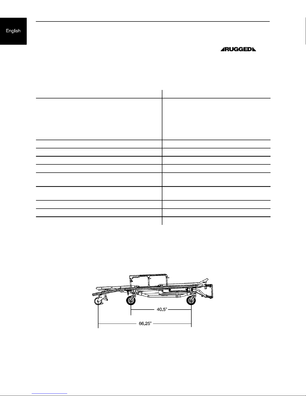
Overall Length/Minimum Length/Width 80.5”/61.75”/23”
Height! -- Position 1
Position 2
Position 3
Position 4
Position 5
Position 6
Position 7
Backrest Articulation/Shock Position 2_ to 73° /+14_
Weight@ 81 pounds
Maximum Weight Capacity 650 pounds
Caster Diameter/Width 6”/2”
Minimum Operators Required for Loading/Unloading
an Occupied Cot
Recommended Fastener Systems Model 6370/6374/6377/6378 Floor Mount Type
Recommended Floor Height# Up to 32”
Roll--In Style Yes
Single Wheel Lock / Double Wheel Lock Optional
13.5”
21.0”
25.5”
29.0”
32.0”
35.0”
37.5
2
Model 6371/6375 Wall Mount Type
! Height measured from bottom of mattress at seat section to ground level.
@ Cot is weighed without mattress and restraints.
# Cot may be loaded from any height and a height limiting kit (p/n 6060--202--000) is available to limit the load height of the cot.
Stryker reserves the right to change specifications without notice.
The MX--PRO is designed to conform to the FederalSpecification for the Star--of--Life Ambulance KKK--A--1822.
Figure 1 -- Lowest Height Position
The yellow and black color scheme is a proprietary trademark of Stryker Corporation.
1-- 2
Page 5

Introduction
WARNING / CAUTION / NOTE DEFINITION
The words WARNING, CAUTION and NOTE carry special meanings and should be carefully reviewed.
WARNING
Thepersonalsafety of thepatient orusermaybeinvolved. Disregarding this informationcouldresult ininjury
to the patient or user.
CAUTION
These instructions point out special proceduresor precautions that must be followed to avoid damaging the
equipment.
NOTE
This provides special information to make maintenance easier or important instructions clearer.
1-- 3
Page 6

Warranty
StrykerEMS,a division of the StrykerCorporation,offerstwodistinct warrantyoptions
in the United States:
One(1)yearpartsand labor. Under this option, StrykerEMS warrantsto theoriginal
purchaserthatits products should be free frommanufacturingnon--conformancesthat
affect product performance and customer satisfaction for a period of one (1) year after
date of delivery. Stryker’s obligation under this warranty is expressly limited to supplying replacement parts and labor for, or replacing, at its option, any product that is, in
the sole discretion of Stryker, found to be defective.
Two (2) yearparts.Under this option, Stryker EMS warrants to the originalpurchas-
er that non--expendable components of its products should be free from manufacturing non--conformances that affect product performance and customer satisfaction for
a period of two (2) years after date of delivery. Stryker’s obligation under thiswarranty
is expressly limited to supplying replacement parts for, or replacing, at its option, any
product which is, in the sole discretion of Stryker, found to be defective. Expendable
components, i.e. mattresses, restraints, IV poles, storage nets, storage pouches, O2
straps, and other soft goods, have a one (1) year limited warranty with this option.
Under either warranty option, Stryker Medical EMS products are designed for a
ted service life under normal use, conditions, and with appropriate periodic
expec
maintenance as described in the maintenance manual for each device. Stryker warrants to the original purchaser that the welds on its EMS products will be free from
structuraldefectsfor the expected
c
haser owns theproduct. Originalpurchasers will also obtain a three (3) year limit-
pur
ed parts warranty for the X frame components of the MX--PRO R3 stretcher provided
they also purchaseX--frame guardsat the time of the originalpurchaseand the guards
are installed on the MX--PRO before it is put into service.
If Stryker requests,products or parts for which an original purchaser makes a warranty
claim,the purchasershall return the productor part prepaid freight to Stryker’sfactory.
Any improper use or alteration or repair by unauthorized service providers in such a
manner as in Stryker’s judgment affects the product materially and adversely, shall
void this warranty. Any repair of Stryker products using parts not provided or authorized by Stryker shall void this warranty. No employee or representative of Stryker is
authorized to change this warranty in any way.
This statement constitutes Stryker EMS’s entire warranty with respectto the aforesaid
equipment.STRYKERMAKES NOOTHERWARRANTYORREPRESENTATIONEITHER EXPRESSED OR IMPLIED, EXCEPT AS SET FORTH HERIN. THERE IS NO
WARRANTY OF MERCHANTABILITY AND THERE ARE NO WARRANTIES OF FITNESS FOR ANY PARTICULARPURPOSE. IN NO EVENT SHALL STRYKERBE LIABLE HEREUNDER FOR INCIDENTAL OR CONSEQUENTIAL DAMAGES ARISING FROM OR IN ANY MANNER RELATED TO SALES OR USE OF ANY SUCH
EQUIPMENT.
ear life of the EMS product as long as the original
5 y
5 y
ear
1-- 4
Page 7

Warranty
Stryker EMS Return Policy
Cots, Stair Chairs, Evacuation Chairs, Cot Fasteners and Aftermarket Accessories:
may be returned up to 180 days of receipt if they meet the following guidelines:
Prior to 30
S 30 day money back guarantee in effect
S Stryker EMS is responsible for all charges
S Returns will not be approved on modified items
Prior to 90
S Product must be unused, undamaged and in the original packaging
S Customer is responsible for a 10% restocking fee
Prior to 180
S Product must be unused, undamaged and in the original packaging
S Customer is responsible for a 25% restocking fee
Return Authorization:
Merchandisecannot be returnedwithoutapprovalfrom the StrykerCustomerService
Department. An authorization number will be provided whichmust be printed on the
returned merchandise. Stryker reservesthe right to charge shipping and restocking
fees on returned items.
SPECIAL, MODIFIED, OR DISCONTINUED ITEMS NOT SUBJECT TO RETURN.
Days
Days
Days
Damaged Merchandise:
ICCRegulationsrequirethat claimsfor damaged merchandisemustbemade withthe
carrier within fifteen (15) days of receipt of merchandise. DO NOT ACCEPT DAMAGED SHIPMENTS UNLESS SUCH DAMAGE IS NOTEDON THE DELIVERY RECEIPT ATTHETIME OFRECEIPT. Upon promptnotification, Strykerwill file a freight
claimwiththeappropriatecarrierfordamagesincurred. Claimwillbelimitedinamount
to the actual replacement cost. In the event that this information is not received by
Strykerwithinthe fifteen (15)day period following the deliveryof the merchandise, or
the damage was not noted on the delivery receiptat the timeof receipt, the customer
will be responsible for payment of the original invoice in full.
Claims for any short shipment must be made within thirty (30) days of invoice.
International Warranty Clause:
This warranty reflects U.S. domestic policy. Warranty outside the U.S. may vary by
country. PleasecontactyourlocalStrykerMedicalrepresentativeforadditionalinformation.
Patent Information
Ruggedr Products are covered by one or more of the following patents:
United States 5,575,026 6,276,010 6,648,343 6,908,133 6,796,757
5,537,700 6,125,485 6,735,794 7,100,224 D527,103
Other Patents Pending
1-- 5
Page 8

Summary of Safety Precautions
The following is a list of safety precautions that must be observed when operatingor servicingthis unit. The
precautions are repeated throughout the manual, where applicable. Carefully read this list before using or
servicing the unit.
WARNING
S Improper usage of the
only as described in this manual.
S Always use all restraint straps to securethepatienton the cot. An unrestrainedpatient may fall from the
cot and be injured.
S Siderails are not intended toserve as apatient restraint device. Refer to pages 1--12and 1--13for proper
restraint strap usage. Failure to utilize the siderails properly could result in patient injury.
S Never leave a patient unattended on the cot or injury could result. Hold thecot securely while a patient
is on the cot.
S Never apply the optional wheel lock(s)while a patient is on the cot. Tipping could occur if thecot is moved
while wheel locks are applied, resulting in injury to the patient or operator and/or damage to the cot.
S Wheel locks are only intendedto help prevent the cot from rollingwhile unattended. Wheel locks may not
provide sufficient resistance on all surfaces or under loads.
S Never install or use wheel locks on a cot with excessively worn wheels. Installing or using wheel locks
on wheels with less than a 6” diameter couldcompromise the holding ability of the wheel lock, resulting
in injury to the patient or operator and/or damage to the cot or other equipment.
S Be sure the undercarriage has engaged and locked beforeremovingtheloading wheels from the patient
compartment floor of the vehicle. An unlocked undercarriagewill not support the cotand injury to the patient and/or operator could result.
S Do not allow untrained helpers to assist in the operation of the cot. Untrained technicians/helpers can
cause injury to the patient or themselves.
S Grasping the
Keep hands, fingers and feetaway frommovingparts. T oavoid injury,use extreme caution when placing
your feet near the base tubes while raising and lowering the cot.
S Have the vehicle safety hook installed by a certified mechanic. Improper safety hook installation can
cause injury to the patient or operator or damage to the unit.
S Failure tousethevehicle safety hook cancauseinjurytothe patient or operator. Install and usethesafety
hook as described in this manual.
S When the optional head end storage pouch is being used, ensure it does not interfere withthe operation
of the safety bar and safety hook. Injury to the patient or operator could occur.
S Donot pull orliftonthesafety barwhenunloading thecot. Damage tothesafetybar couldresultandinjury
to the patient or operator could occur.
S Do not modify the
in injury to the patient or operator. Modifying the cot will also void its warranty (see page 1--4).
S Improper maintenance can cause injuryordamageto theunit. Maintainthecotasdescribedin thismanu-
al. Use only Stryker approved parts and maintenanceprocedures. Using unapproved parts and procedures could cause unpredictable operation and/or injury and will void the product warranty.
S Do not ride on the base of the
to the patient or operator.
S Failure to properly clean or dispose of contaminatedmattress or cot components will increase therisk of
exposure to bloodborne pathogens and may cause injury to the patient or the operator.
S To avoidaccidentalrelease of the Pedi--Matet, and possible injuryto the infant, ensure the buckle is lo-
cated away from obstructions on the cot or head end storage pouch.
S Operating the cot with the breakaway head section lowered may cause injury to the patient or operator
or damage to the cot. Use only positions 5--7 when using this configuration.
Cot improperly can cause injury. Grasp only the lifting bars to lift thecot.
Cot cancause injury to the patient or operator. Operate the cot
Cot. Modifying the cot can cause unpredictable operation resulting
cot. Damage to the cot could occur, resulting in injury
1-- 6
Page 9

Summary of Safety Precautions
CAUTION
S Damage tothe cot can occur if the cot is lowered in the shortened position. Use only positions 5--7 (see
page 1--11) when the cot is shortened.
S Lifting the cot by the safety bar can cause damage to the cot. Lift the cot only by the lifting bars.
S Do not allow the cot undercarriage to drop unassisted (commonly known as a “hot drop”) when removing
the cot from the vehicle. Repeated hot dropping will cause premature wear or damage to the cot.
S Height limit kit is recommended for ambulance deck heights less than 30 inches (76cm) — Strykerpart
number 6060--202--000.
S The weight of the monitoringequipment must not exceed 75 pounds (34 kg) with the defibrillatorplatform
(if equipped). Monitoring equipment should not be stored on the cot or on the defibrillator platform when
in the ambulance vehicle.
1-- 7
Page 10

Set--Up Procedures
Ensure that all shipping and packaging materials have been removed from the product(s) prior to use.
Unpack the cartons and check all items for proper operation. It is important that the
working properly before it is put into service. Have a qualified serviceperson use the following list and the
operation instructions to check the cot before it is put into service.
S All fasteners secure (reference all assembly drawings)
S All welds intact, not cracked or broken
S No bent or broken tubing or sheet metal
S No debris in wheels
S All wheels secure, rolling and swivelling properly
S Siderails move and latch properly
S Backrest operating properly
S Optional accessories intact and operating properly
S Height positioning latch functioning properly
S Cot secure in each height position
S Undercarriage folds properly
Cot is
S Breakaway head section operating properly
S Safety bar operating properly
S Foot rest operating properly
S No rips or cracks in mattress cover
S Body restraints intact and working properly
S Wheel lock(s) operating properly (optional equipment)
S Does the vehicle safetyhook engage the safety bar so thatthecotloads and unloads easily from the ve-
hicle?
S Is there an approved crash--stable fastener (Stryker part number 6370/6374/6377/6378or 6371/6375 --
not included) installed in the vehicle?
The patient compartment of the vehicle in which the
S A smooth rear edge for cot loading.
S A level floor large enough for the folded cot.
S Stryker 6370/6374/6377/6378 or 6371/6375 crash stable cot fastener (not included).
S 32” (81 cm.) maximum loading height.
S Space to install the safety hook.
When necessary, modify the vehicle to fit the cot. Do not modify the cot.
Cot will be used must have:
WARNING
Donot modifythe Cot. Modifyingthe cot can cause unpredictable operationresulting in injury to the patient or operator. Modifying the cot will also void its warranty (see page 1--4).
1-- 8
Page 11
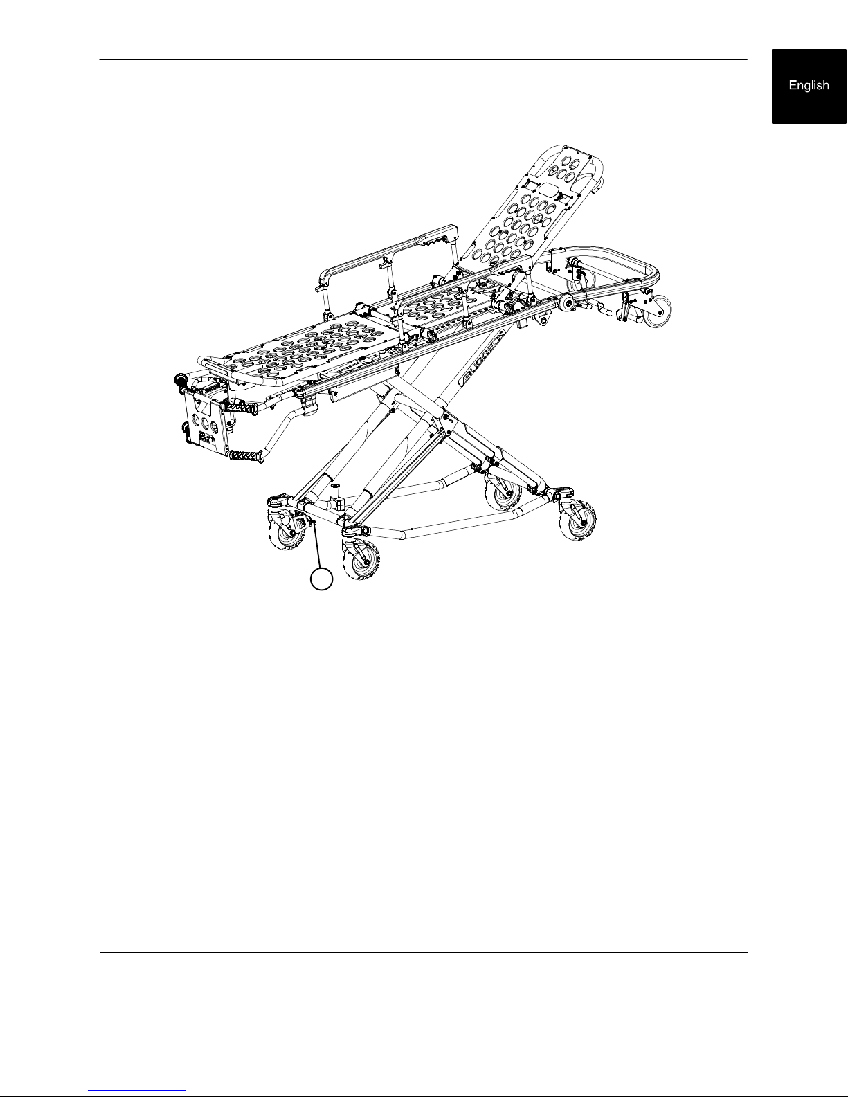
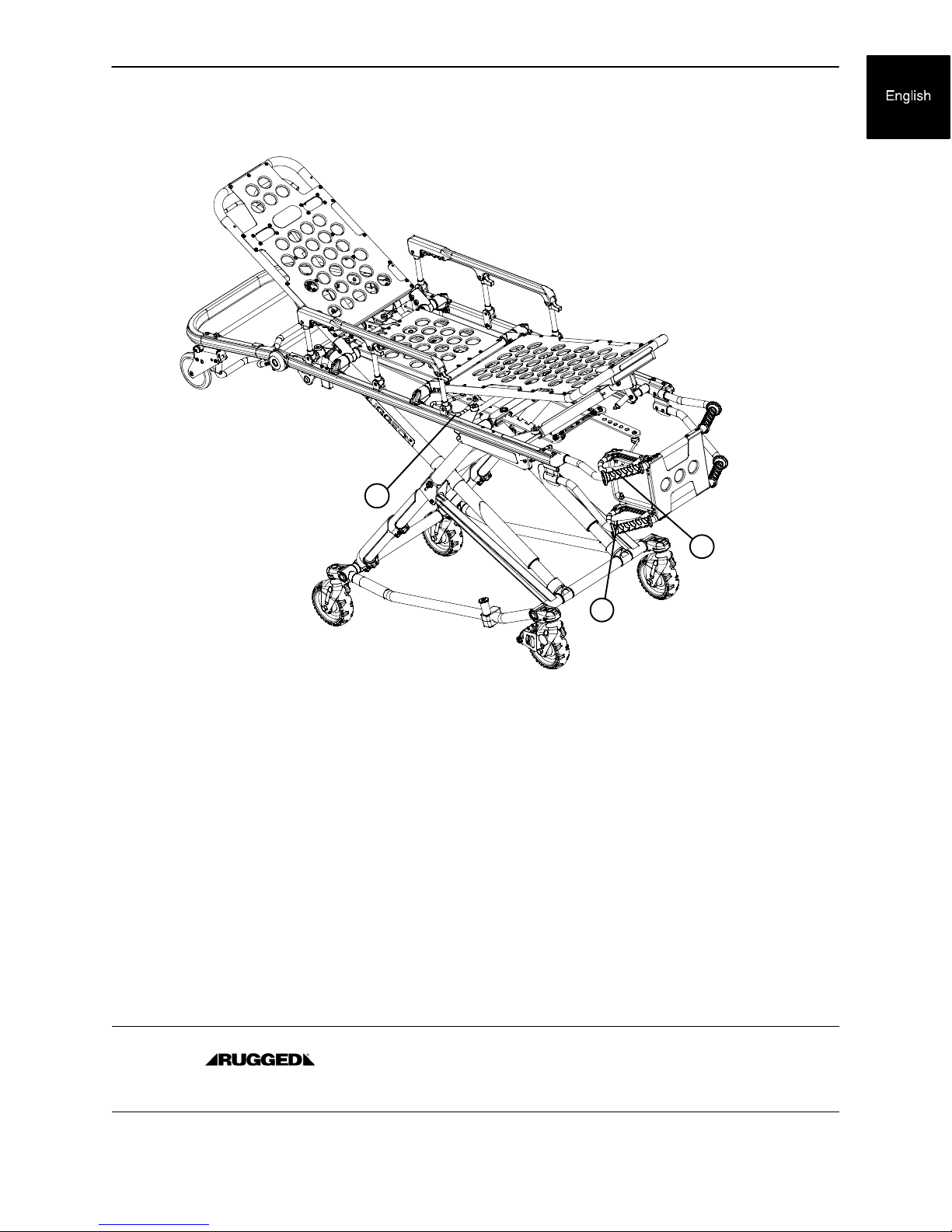
Component Identification
t
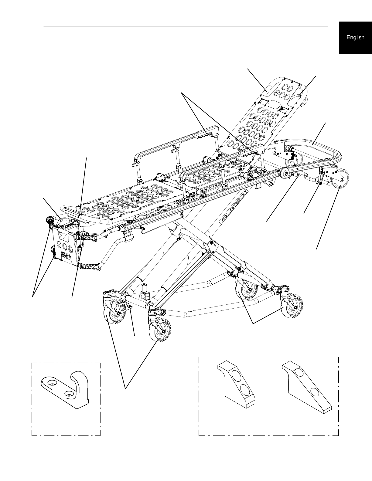
Figure 2 -- MX--PRO R3 Cot
HeightAdjustment
Release Handle
(1 of 3)
Foot Rest
SiderailRelease Handles
Backrest (Head Section)
Breakaway
Head Section
Release Bar
BackrestAdjustmen
Release Handle
HEAD END
Breakaway
Head Section
Safety Bar
Release
Lever
LiftingBar
J Safety Hook
Strykerpart number
6092--036--018
Loading Wheels
(1 of 2)
Foot Rest
Release
Handle
TransportWheels
Wheel Lock
(Optional)
TransportWheels
LONG SAFETY HOOKSHORT SAFETY HOOK
(Forinstallationinstructions,see page1 -- 10.)
1-- 9
Page 12
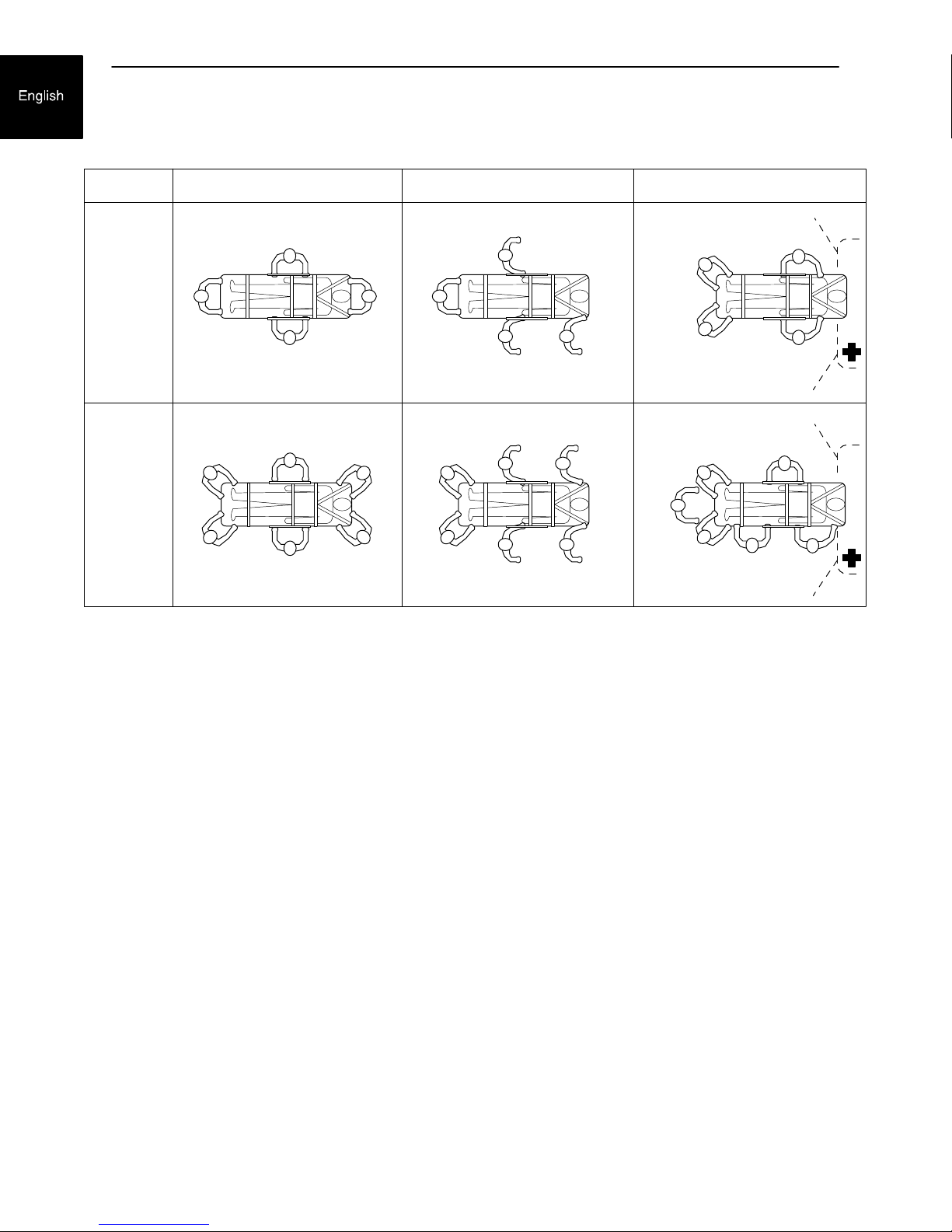
Vehicle Safety Hook Selection
The vehicle safety hook is a device that ships with the cot. The cot safety bar and vehicle safety hook are designed
to keep the cot from being accidentally removed from the vehicle and to provide increased operator assurance and
confidence when loading and unloading. The safety hook was designed for compatibility and proper operation when
loading and unloading the cot from a vehicle that is compliant with Federal Regulation KKK-A-1822.
Stryker offers three different types of safety hooks that are ordered and shipped with your ambulance cot. These
safety hook types are designed to meet the needs of various emergency vehicle configurations, specifically the length
and location of the floor structure support that is located in the rear of the vehicle.
Consider the following information when selecting
which safety hook is appropriate for your vehicle
configuration:
• Determine the location of the floor structure
support where there is adequate room to mount
the safety hook.
• Ensure that the safety hook can be securely
mounted into the back of the vehicle while
providing adequate bumper clearance to allow the
cot to be loaded and unloaded from the vehicle.
• Note the differences in vehicle design. Each safety
hook provides a different mounting location option
to maintain the appropriate distance between the
face of the safety hook and the edge of the door
sill.
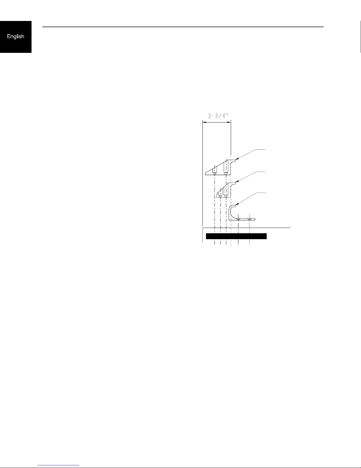
Long Safety Hook
6060-036-018
Short Safety Hook
6060-036-017
J-Style Safety Hook
6092-036-018
Due to the differences in vehicle dimensions and the
floor structure support locations, each safety hook
requires a different mounting location. See “Vehicle
Safety Hook Installation” to determine the correct
positioning for safety hook installation.
Safety Hook Types
Note: When replacing an existing safety hook with a new style, adjust the mounting location to maintain the proper
position of the safety hook face.
1--10
Page 13
Vehicle Safety Hook Installation
VEHICLE CONFIGURATION
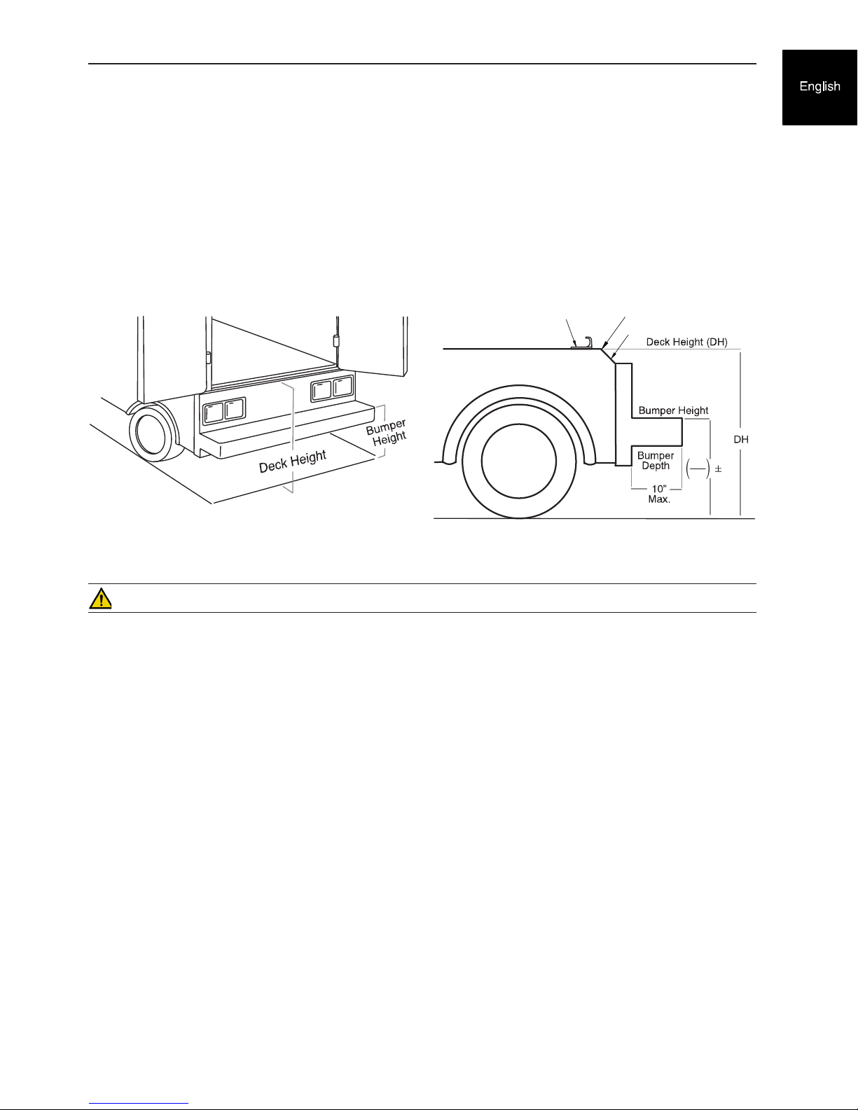
According to federal regulations (reference KKK-A-1822), the bumper height of the vehicle shall be installed equidistant
± 5 cm (2 inches) from the vehicle floor to the ground level, which is defined as the vehicle deck height. The bumper
step shall have a minimum depth of 13 cm (5 inches) and a maximum depth of 25 cm (10 inches). If the bumper depth
is greater than 18 cm (7 inches), then the bumper must be able to fold. Installation of the safety hook into any vehicle
compliant with this federal specification provides adequate clearance for the cot base to lower to its fully extended
position. The cot is compatible with all vehicle deck heights (see specifications for maximum load height) as long as
the vehicle meets the federal specifications that are outlined in KKK-A-1822.
Sill Edge
Sill
DH
2
2
Vehicle Deck Height
Safety Hook
Vehicle Deck Height
CAUTION
• Set the cot load height to the proper stop height prior to operation.
• Installation of the safety hook should be done by a certified mechanic familiar with ambulance vehicle construction.
Consult the vehicle manufacturer before installing the safety hook and be sure that the installation of the safety
hook does not damage or interfere with the brake lines, oxygen lines, fuel lines, fuel tank or electrical wiring of
the vehicle.
REQUIRED HARDWARE FOR INSTALLATION OF THE SAFETY HOOK (NOT SUPPLIED)
(2) Grade 5, 1/4”-20 Socket Head Cap Screws*
(2) Grade 5, 1/4”-20 Flat Socket Head Cap Screws*
(2) Flat Washers
(2) Lock Washers
(2) 1/4”-20 Nuts
* The length of the socket head cap screws depends on the thickness of the vehicle floor. Use screws that are long
enough to go completely through the patient compartment floor, washer and nut by at least two full threads.
1--11
Page 14

Vehicle Safety Hook Installation
WARNING
• Have the vehicle safety hook installed by a certified mechanic. Improper safety hook installation can cause injury
to the patient or operator and/or damage to the cot.
• Failure to install the safety hook can cause injury to the patient or operator.
• The face of the safety hook that engages the safety bar should be located at least 3-3/4” from the leading edge
of the door sill. After installation, verify that the cot legs lock into the load position without contacting the vehicle
bumper.
• To avoid injury, verify that the safety bar has engaged the safety hook before removing the cot from the patient
compartment.
Note: Stryker recommends that, prior to installation, the certified mechanic plan the placement of the safety hook in
the rear of the vehicle.
Before installing the safety hook into your vehicle, check the front to back and side to side positioning when unloading
and loading the cot to ensure that the safety hook will be installed properly. The cot safety bar must engage the safety
hook every time, regardless of cot position.
FRONT TO BACK POSITIONING OF THE SAFETY HOOK
1. Select the appropriate safety hook for your vehicle configuration.
2. Position the safety hook at least 3-3/4” from the leading edge of the door sill.
3. Ensure that the safety hook can be securely mounted into the back of the vehicle while providing adequate bumper
clearance to allow the cot to be loaded and unloaded from the vehicle.
4. See “Side to Side Positioning of the Safety Hook” to confirm the side to side placement.
Safety Hook Placement
Long Safety Hook
6060-036-018
Short Safety Hook
6060-036-017
J-Style Safety Hook
6092-036-018
1--12
Page 15
Vehicle Safety Hook Installation
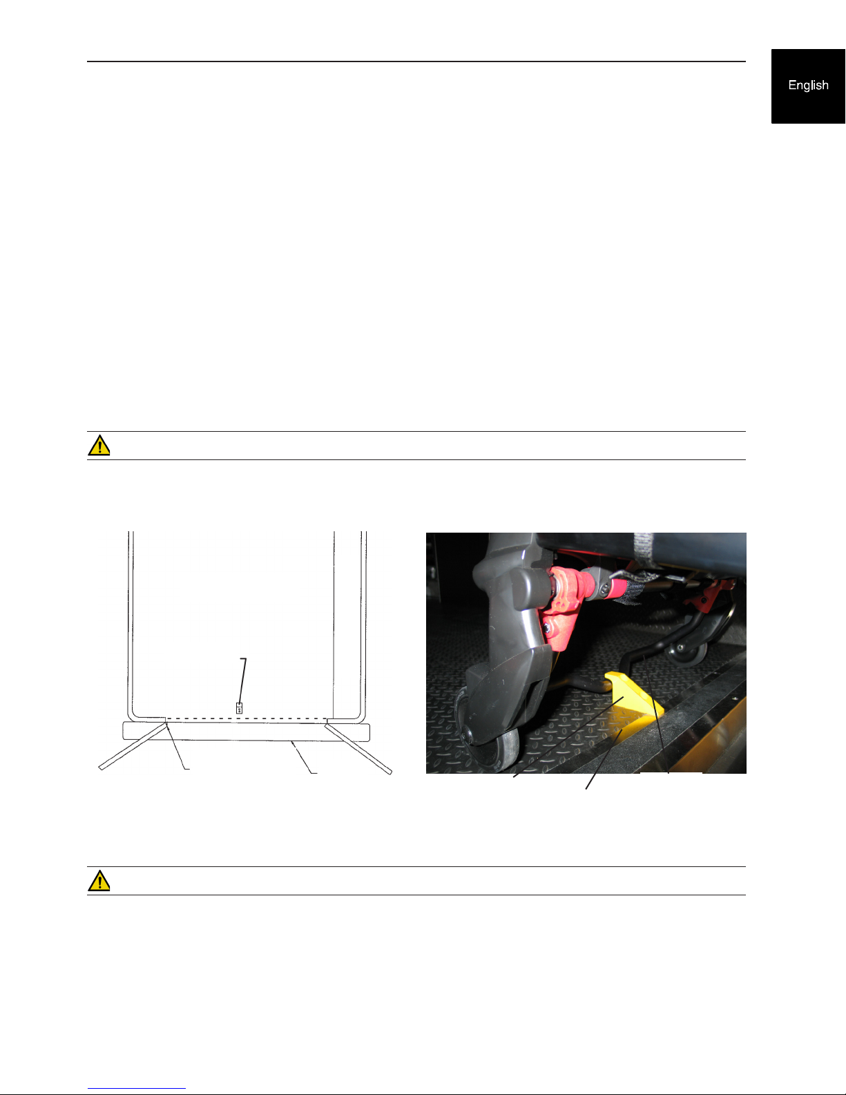
SIDE TO SIDE POSITIONING OF THE SAFETY HOOK
1. Remove the cot from the fastener and unload it from the vehicle.
2. While the cot is being removed, note the position of the load wheels and the safety bar.
3. Mark the center of the cot safety bar on the vehicle floor.
4. Verify that the position marked in Step 3 is where the safety bar engages the safety hook every time when unloading
the cot in a variety of positions (all the way to the left and all the way to the right), regardless of cot position.
• If the cot safety bar does not engage the safety hook in any of these positions (left, center, or right), modify
the vehicle, not the cot or safety hook.
• If the cot safety bar engages the safety hook every time, install the safety hook.
INSTALLING THE SAFETY HOOK
1. Determine the correct safety hook front to back and side to side positioning, so the cot safety bar engages the
safety hook every time.
2. Drill the holes for the socket head cap screws.
3. Fasten the safety hook to the patient compartment floor and verify that the safety hook always engages the cot
safety bar regardless of how the cot is unloaded from the vehicle.
WARNING
Verify that the safety hook always engages the cot safety bar regardless of how the cot is unloaded from the vehicle
or injury to the patient or operator and/or damage to the cot may occur.
Top View of Vehicle
Bumper
Squad Bench
Safety Hook
Safety Bar Engaging Safety Hook
Floor Edge
Safety Bar
Safety Hook
Door Frame
Safety Hook Placement
(For Reference Only)
WARNING
The cot must have at least 5/8” of clearance between the vehicle bumper and the cot to disengage the safety bar when
unloading the cot from the vehicle. Verify that the cot legs lock into the load position before disengaging the safety
bar from the safety hook. Failure to properly lock the cot into position can cause injury to the patient or operator and/
or damage to the cot.
1--13
Page 16

Note
1-14
Page 17
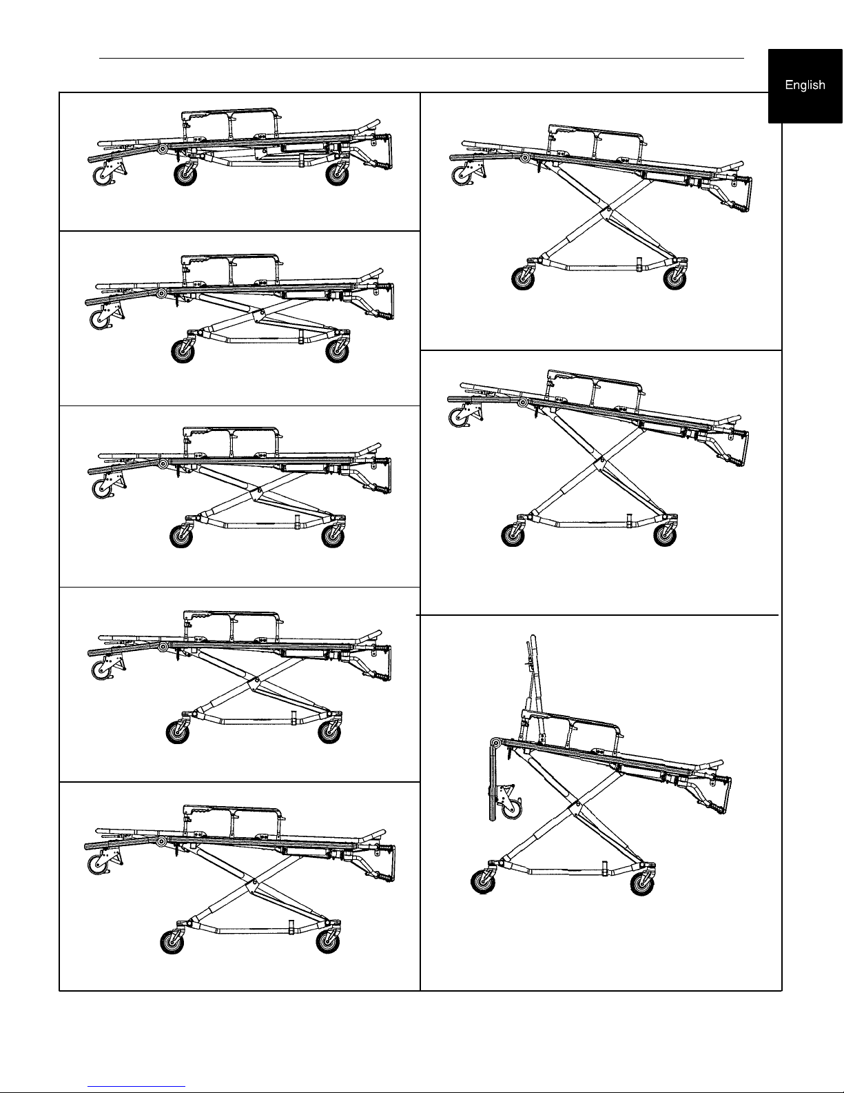
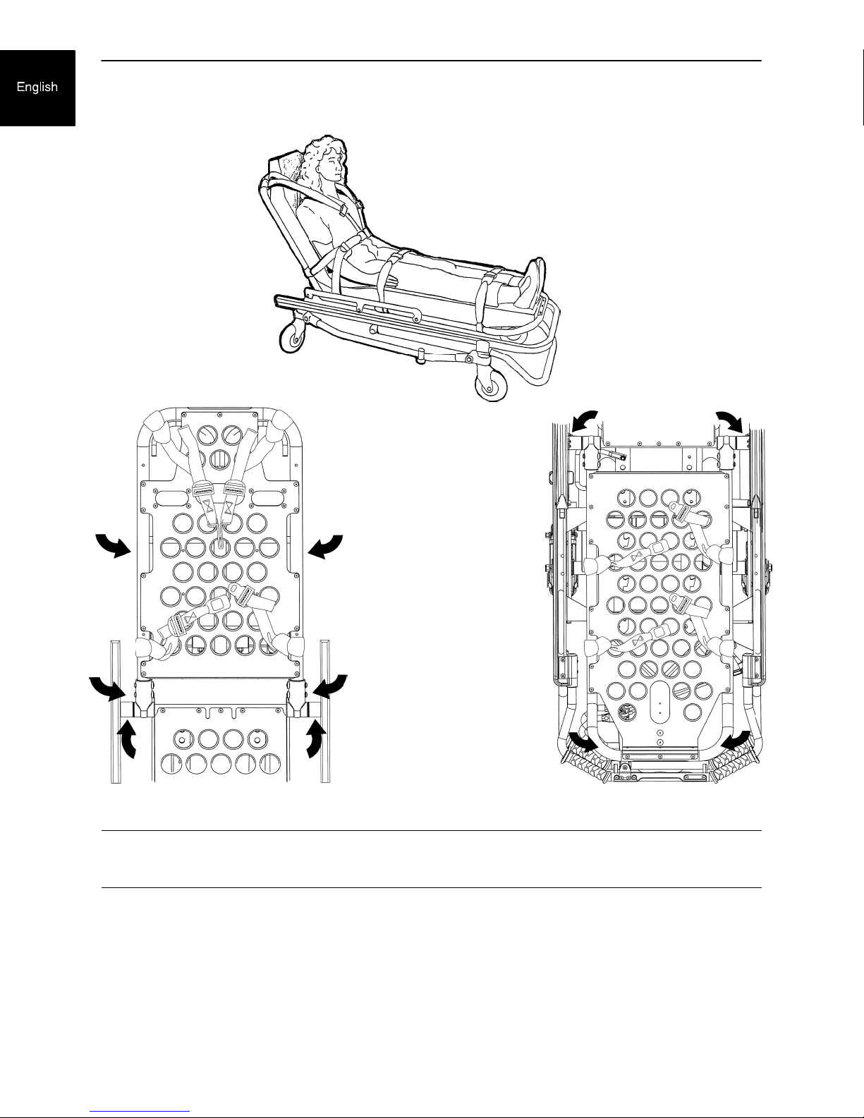
Cot Positions
Position 1 - Use for patient transfer.
Position 2 - Use for patient transfer/cot rolling.
Position 6 - Use for patient transfer/cot rolling.
Position 3 - Use for patient transfer/cot rolling.
Position 4 - Use for patient transfer/cot rolling.
Position 5 - use for patient transfer/cot rolling.
Position 7 - Use for patient transfer/cot rolling.
WARNING - Operating the cot with the breakaway
head section lowered may cause injury to the patient
or operator or damage to the cot. Use only positions
5-7 when using this configuration.
1-15
Page 18
Using Restraint Straps
Cot Operation
Figure 6 - Safety Restraints
Figure 7 - Back Rest Restraints Figure 8 - Foot Section Restraints
WARNING
Always use all restraint straps to secure the patient on the cot. An unrestrained patient may fall from the cot
and be injured.
Always secure the patient on the cot with all the restraint straps. Buckle the restraints across the patient's
chest/shoulders, waist and legs (Figure 6). Keep the restraint straps buckled when the cot is not being used
with a patient to avoid damage to the buckles and straps.
When attaching the restraint straps to the cot, keep in mind the attachment points should provide strong an‐
chorage and proper restraint position while not interfering with equipment and accessories. Wrap the strap
around the cot frame and back through the loop on the end of the strap as shown in Figures 7 and 8. The
arrows indicate alternate attachment areas.
1-16
Page 19
Cot Operation
Using Restraint Straps (Continued)
C
C
A
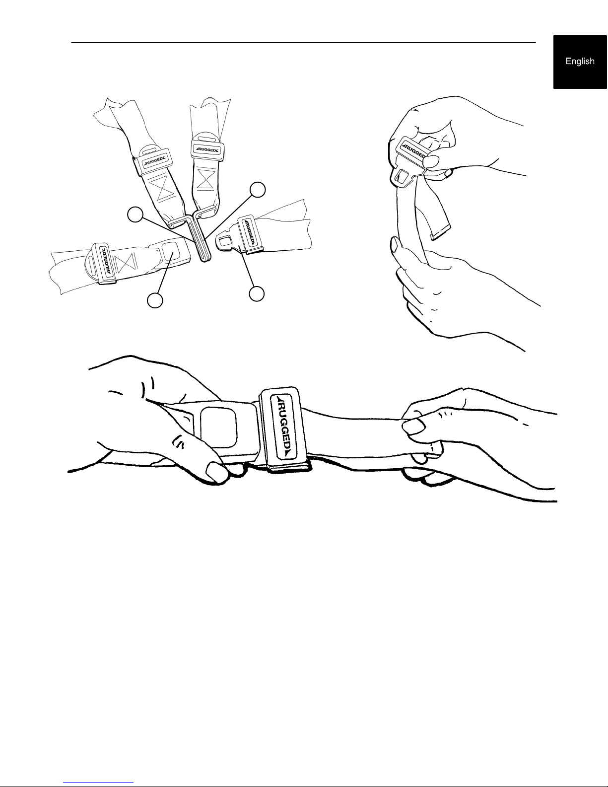
Figure 9 - Buckling the Safety Restraint
Figure 11 - Shortening the Safety Restraint
When the cot is put into service, the restraints are opened and placed to either side of the cot until the patient
is positioned on the cot mattress. The restraint is lengthened, buckled around the patient and shortened until
the required tightness is achieved.
To open the restraint, press the red button (A) on the front of the buckle ”receiver”. This releases the buckle
”tang” (B) which can then be pulled out of the receiver (Figure 9).
To close the restraint, push the tang into the receiver until a ”click” is heard. When fastening the chest restraint
be sure the tang passes through both links (C) on the shoulder strap (Figure 9).
To lengthen the restraint, grasp the buckle tang, turn it at an angle to the webbing, then pull it out (Figure 10).
A hemmed tab at the end of the webbing prevents the tang from coming off the strap.
To shorten the restraint, grasp the hemmed tab and pull the webbing back through the tang until the required
tightness is achieved (Figure 11).
Whenever a restraint is buckled on a patient, the attendant should check to be sure the tang is fully engaged
and that the extra webbing is not tangled in the cot or hanging loose.
Inspection of the restraints should be done at least once a month (more frequently if used heavily). Inspection
should include checking for a bent or broken receiver or tang, torn or frayed webbing, etc. Any restraint show‐
ing wear or not operating properly must be replaced immediately.
B
Figure 10 - Lenghtening the Safety Restraint
1-17
Page 20
Pedi-Mate t Infant Restraint System Attachment Instructions
Refer to the Pedi-Matet users manual for the manufacturer's recommendations for the use, operation and
care of the Pedi-Matet Infant Restraint System.
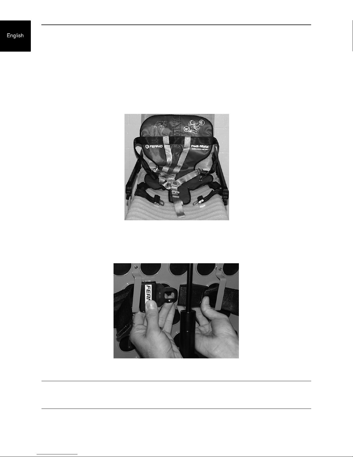
Securing the Pedi-Matet to the cot
1. Remove any restraints already attached to the cot.
2. Raise the cot backrest to the full upright position.
3. Position the Pedi-Matet pad flat on the backrest with the black backrest straps out (see Figure 12).
Figure 12 - Positioning the Pedi-Matet
4. Wrap the straps around the backrest and insert the ends of the straps through the brackets. Securely
fasten the buckle (see Figure 13).
Figure 13 - Fastening the Pedi-Matet Buckle
WARNING
To avoid accidental release of the Pedi-Matet, and possible injury to the infant, ensure the buckle is located
away from obstructions on the cot or head end storage pouch.
1-18
Page 21

Pedi-Mate t Infant Restraint System Attachment Instructions
5. Pull firmly on the end of the adjustable backrest strap and tighten it securely.
6. Thread the mainframe straps down between the cot frame and the mattress. To be sure the release but‐
ton is toward the foot end of the cot, insert the buckle behind the crossbrace and bring the it up in front
of the crossbrace. Secure the buckle around the litter crossbrace leaving a little slack in the strap for final
adjustment (see Figure 14).
Figure 14 - Securing the Safety Restraints on a RuggedtCot
WARNING
To avoid accidental release of the Pedi-Matet, and possible injury to the infant, ensure the buckle is located
away from obstructions on the cot.
7. Verify all the straps are snug and fastened securely (see Figure 15).
Figure 15- Pedi-Matet Strapped to a Ruggedt Cot
These are general instructions for installation of the Pedi-Matet. Safe and proper use of the Pedi-Matet is solely at
the discretion of the user. Stryker recommends all users be trained on the proper use of the Pedi-Matet before using it
in an actual situation.
Retain these instructions for future reference. Include them with the product in the event of transfer to new users.
Pedi-Mate t is a trademark of Ferno-Washington Inc.
1-19
Page 22

Cot Operation
Operating Guidelines
S Use the Cot only as described in this manual.
S Read all labels and instructions on the cot before using the cot.
S Use a minimum of two operators to manipulate the cot while a patient is on the cot.
S Do not adjust, roll or load the cot without advising the patient. Stay with the patient and control the cot
at all times.
S Never apply the optional wheel lock while a patient is on the cot.
S Always use the restraint straps and keep the siderails up when a patient is on the cot.
S Use properly trained helpers when necessary to control the cot and patient.
Transferring the Patient to the Cot
1. Roll the cot to the patient.
2. Place the cot beside the patient and raise/lower the cot to the patient's level.
3. Lower the siderails and open the restraint straps.
4. Transfer the patient to the cot using accepted EMS procedures.
5. Use all the restraints to secure the patient to the cot (see page 1-16 for restraint strap usage instructions).
6. Raise the siderails and adjust the backrest and leg rest as necessary.
WARNING
Always use all restraint straps to secure the patient on the cot. An unrestrained patient may fall from the cot
and be injured.
Never apply the optional wheel lock while a patient is on the cot. Tipping could occur if the cot is moved while
the wheel lock is applied, resulting in injury to the patient or operator and/or damage to the cot.
Rolling the Cot
1. Make sure all the restraint straps are securely buckled around the patient (see page 1-16 & 1-17 for re‐
straint strap usage instructions).
2. Place the cot in positions 2-7 for rolling (see page 1-15 for cot positions).
3. When rolling the cot, position an operator at the foot end and one at the head end at all times.
NOTES
Loose items or debris on the patient compartment floor can interfere with the operation of the safety hook
and cot fastener. Keep the patient compartment floor clear.
The cot can be loaded with the siderails down only if the restraint belts are properly buckled around the patient.
WARNING
Operating the cot with the breakaway head section lowered may cause injury to the patient or operator or
damage to the cot. Use only positions shown on the Cot Positions page when using this configuration.
1-20
Page 23
Cot Operation
Loading the Cot into a
Vehicle with Two Operators
When loading the cot into a vehicle, an operator
should remember the following important issues:
S Two operators must be present when the cot is
occupied.
S There must be a safety hook properly installed
in the vehicle so that the bumper does not inter‐
fere with the front legs of the base frame. (See
page NO TAG, safety hook installation instruc‐
tions.)
S Operators must be able to lift the total weight of
the patient, cot and any items on the cot.
S The higher an operator must lift the cot, the more
difficult it becomes to hold the weight. An opera‐
tor may need help loading the cot if he/she is too
short or if the patient is too heavy to lift safely.
The operator must be able to lift the cot high
enough for the cot's legs to unfold completely
and lock when the cot is unloaded. A shorter op‐
erator will have to raise his/her arms higher to
enable the undercarriage to unfold.
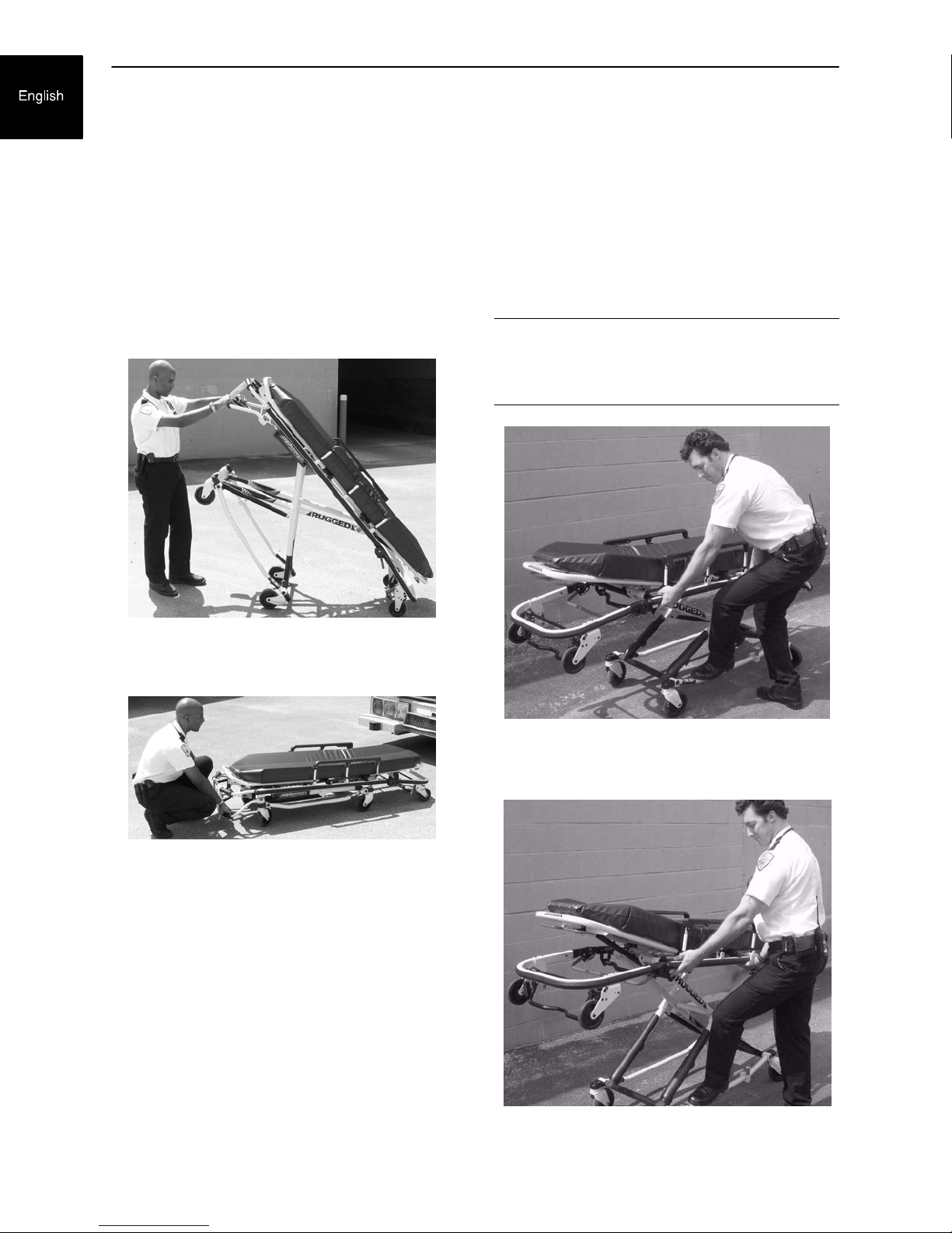
1. Place the cot in a loading position (any position
where the loading wheels meet the vehicle floor
height). Roll the cot to the open door of the pa‐
tient compartment. Lift the vehicle bumper to
the raised position (if possible).
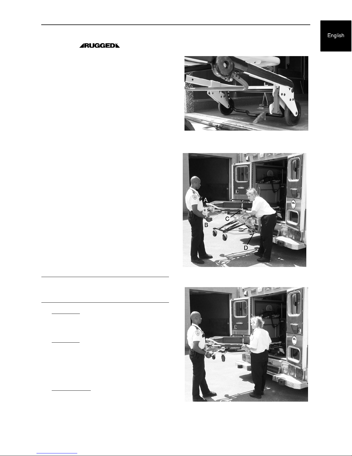
2. Push the cot forward until the loading wheels
are on the patient compartment floor and the
safety bar passes the safety hook (Figure 16).
3. For maximum clearance to lift the base, pull the
cot back until the safety bar engages the safety
hook.
WARNING
Failure to use the safety hook can result in injury.
Install and use the hook as described in this manual.
Figure 16 - Safety Bar Engaging Safety Hook
Figure 17 - 2 Operators - One Lifting the Base
4. Operator 1 - Grasp the cot frame at the foot
end. Lift the foot end of the cot until the weight
is off the latching mechanism. Squeeze and
hold the release handle (location A or B).
5. Operator 2 - Stabilize the cot by placing your
hand on the outer rail (location C). Grasp the
base frame where indicated (location D). After
the foot end operator has lifted the cot and
squeezed the release handle, raise the under‐
carriage until it stops in the uppermost position
and hold it there (Figure 17).
6. Both Operators - Push the cot into the patient
compartment (Figure 18), engaging the cot fas‐
tener (not included).
Figure 18 - 2 Operators - Base Full Up
1-21
Page 24

Cot Operation
Loading an Empty Cot into a
Vehicle with One Operator
WARNING
This procedure is for use only with an empty cot. Do
not use this procedure when loading a patient. Inju‐
ry to the patient and/or operator could result.
1. Place the cot in a loading position (any position
in which the load wheels meet the vehicle floor
height – see page 1-15 ).
2. Roll the cot to the open door of the patient
compartment.
3. Lift the vehicle bumper to the raised position (if
possible).
4. Push the cot forward until the loading wheels
are on the compartment floor and the safety bar
passes the safety hook.
5. Pull the cot back until the safety bar engages
the safety hook.
6. Grasp the cot frame at the foot end and
squeeze and hold the release handle (A or B)
(Figure 19).
7. Lower the foot end of the cot to the ground,
making sure the cot locks in position 1 (Figure
20).
8. Lift the foot end of the cot until it is level with the
compartment floor.
9. Grasp the base of the cot with one hand and pull
up the base of the cot towards the litter, reduc‐
ing the space between the base and the litter
(Figure 21).
10. Push the cot into the patient compartment,
guiding it into the cot fastener.
Figure 19 - Squeeze the Release Handle
Figure 20 - Lower the Foot End of the Cot
Figure 21 - Pull Up the Base of the Cot
1-22
Page 25

Cot Operation
Unloading the Cot from a Vehicle with Two
Operators
1. Disengage the cot from the cot fastener. (For
more detailed instructions, reference the cot
fastener installation/operation manual - Stryk‐
er part number 6370-90-10).
2. Operator 1 - Grasp the cot frame. Pull the cot
out of the patient compartment until the safety
bar engages the safety hook.
WARNING
Failure to use the safety hook can cause injury to
the patient or operator. Install and use the safety
hook as described in this manual.
3. Operator 2 - Grasp the base frame where indi‐
cated, lift slightly, and lower the base frame to
its fully extended position while operator 1
squeezes and holds the release handle.
4. Operator 1 - Let go of the release handle and
be sure the undercarriage locks into place.
5. Operator 2 - Disengage the safety bar from the
safety hook by pushing the safety bar release
lever forward.
Unloading an Empty Cot
from a Vehicle with One Operator
WARNING
This procedure is for use only with an empty cot. Do
not use this procedure when unloading a patient. In‐
jury to the patient and/or operator could result.
1. Lift the vehicle bumper to the raised position (if
possible).
2. Grasp the cot frame at the foot end; pull the cot
from the vehicle until the safety bar engages the
safety hook.
3. Lower the foot end of the cot to the ground (see
Figure 20).
4. Squeeze and hold the release handle (A or B see Figure 21) and raise the foot end of the cot
back to a level position with the compartment
floor.
5. Disengage the safety bar from the safety hook
by pushing the safety bar release lever forward
and roll the cot out of the vehicle.
WARNING
Do not pull or lift on the safety bar when unloading
the cot. Damage to the safety bar could result and
injury to the patient or operator could occur.
6. Remove the cot loading wheels from the ve‐
hicle. Place the cot in a rolling position (posi‐
tions 2-7 - see page 1-15 ).
CAUTION
Do not allow the cot undercarriage to drop unassist‐
ed (commonly known as a “hot drop”) when remov‐
ing the cot from the vehicle. Repeated hot dropping
will cause premature wear or damage to the cot.
WARNING
Be sure the undercarriage has engaged before re‐
moving the loading wheels from the patient
compartment floor of the vehicle. An unlocked un‐
dercarriage will not support the cot and injury to the
patient or operator could result.
1-23
Page 26
USING ADDITIONAL ASSISTANCE
Cot Operation
Tw o
Operators
Tw o
Helpers
Tw o
Operators
Four
Helpers
Changing Levels
Helper
Operator Operator
Helper
Helper
Operator
Helper
Helper
Operator
Helper
Operator
Helper
Operator
Rolling
Helper
OperatorHelper
Helper Helper
OperatorHelper
Loading/Unloading
Helper
Operator
Helper
Helper
Operator
Helper
Helper
Operator
Helper
Operator
1-24
Page 27
Cot Operation
OPERATING THE OPTIONAL WHEEL LOCK(S)
A
Figure 22 - Ruggedr Wheel Lock
1. To activate the optional wheel lock(s), press fully down on the pedal (A) until it stops.
2. To release the optional wheel lock(s), depress the upper face of the pedal with your foot or lift up with your
toe under the pedal. The upper portion of the pedal will rest against the caster frame when the wheel
lock is released.
WARNING
Never apply the optional wheel lock(s) while a patient is on the cot. Tipping could occur if the cot is moved
while a wheel lock is applied, resulting in injury to the patient or operator and/or damage to the cot.
Wheel lock(s) are only intended to help prevent the cot from rolling while unattended. A wheel lock may not
provide sufficient resistance on all surfaces or under loads.
Never leave a patient unattended on the cot or injury could result. Hold the cot securely while a patient is
on the cot.
Never install or use a wheel lock on a cot with excessively worn wheels. Installing or using a wheel lock on
a wheel with less than a 6” diameter could compromise the holding ability of the wheel lock, resulting in injury
to the patient or operator and/or damage to the cot or other equipment.
1-25
Page 28

Cot Operation
ADJUSTING THE WHEEL LOCKING FORCE
MINIMUM MAXIMUM
1. To adjust the wheel locking force, remove the hex socket screw from the center of the lock pedal. The
wheel lock is initially assembled with the pedal set at the minimum locking force. The marker on the pedal
(item A) is aligned with the marker on the octagonal sleeve (item B).
2. Remove the sleeve (B). Rotate the sleeve counterclockwise to increase the pedal locking force and
clockwise to decrease the locking force. Insert the sleeve into the pedal. Reinstall the hex socket screw.
3. Test the pedal locking force and verify it holds properly before returning the cot to service.
Figure 23 - Wheel Locking Force Adjustment
1-26
Page 29
Cot Operation
CHANGING COT HEIGHT WITH TWO OPERATORS
C
FOOT END
B
A
Figure 24 - Release Handle Locations
NOTE
Changing the height while a patient is on the cot requires a minimum of two operators, positioned at both ends
or on each side of the cot. Each operator must grasp the cot frame securely.
To lower the cot from the ends, the operator at the foot end of the cot positions his/her hands so the release
handle (A or B) can be squeezed while a secure grip is maintained on the lifting bars. Both operators must
lift the cot until the weight is off the latching mechanism (approximately 1/4”). The operator at the foot end
squeezes and holds the release handle and both operators then raise or lower the cot together. The handle
is released when the desired position is reached. Both operators should maintain a secure grip on the litter
frame until the latching mechanism is securely locked into position.
To lower the cot from the sides, the operator on the patient's right positions his/her hands so he/she can
reach the release handle at the midpoint of the litter (C). Both operators must lift the cot until the weight is
off the latching mechanism (approximately 1/4”). The operator at the patient's right squeezes and holds the
release handle. Both operators then raise or lower the cot together. The handle is released when the desired
position is reached. Both operators should maintain a secure grip on the litter frame until the latching mecha‐
nism is securely locked into position.
WARNING
Grasping the Cot improperly can cause injury. Grasp only the litter frame or the lifting bar
to lift the cot. Keep hands, fingers and feet away from moving parts. To avoid injury, use extreme caution
when placing your feet near the base tubes while raising and lowering the cot.
1-27
Page 30
Cot Operation
Changing the Height of an Empty Cot with One Operator
To raise/lower the cot from the foot end:
1. Standing at the foot end of the cot, grasp the
lower foot end lift tube.
2. Tip the cot up onto the load wheels (Figure 25).
3. Squeeze and hold the release handle and raise
or lower the foot end to the desired position.
4. Lower the cot back onto the four base wheels
(Figure 26).
To raise/lower the cot from the side:
1. Place one foot on the outer base tube.
2. Grasp the side release handle with one hand.
Place your other hand on the outer support rail
to help stabilize the cot (Figure 27).
3. Squeeze the side release handle and raise or
lower the cot to the desired position.
WARNING
If lowering the cot to the lowest position (position 1),
remove your foot from the base tube or injury could
result (Figure 28).
Figure 25 - Cot Tipped on Load Wheels
Figure 26 - Cot Lowered to Ground
Figure 27 - Holding Outer Support Rail
Figure 28 - Lowering Cot from Side
1-28
Page 31

Adjusting the Leg Rest
Cot Operation
A
B
FOOT END
Figure 29 - Leg Rest Elevated
The leg rest is adjustable to allow for elevation of the patient's legs.
To raise the leg rest, lift the leg rest frame (A) as high as possible. The support bracket will engage automati‐
cally. Release the frame after the support bracket has engaged.
To lower the leg rest, lift the leg rest frame (A) and, while holding the frame, lift up on the release handle
(B) until the bracket disengages. Lower the leg rest until flat.
1-29
Page 32

A
HEAD END
Cot Operation
B
Figure 30 - Backrest Elevated and Siderails Raised
Operating the Backrest
To raise, squeeze handle (A) for pneumatic assist in lifting the Backrest to the desired height. Remove
hand(s) from handle when desired height is achieved.
To lower, squeeze handle (A) and push down on the Backrest frame until the Backrest has reached the de‐
sired height. Remove hand(s) from handle when desired height is achieved.
Operating the Siderails
To raise, lift up until the latch clicks and the siderail locks into place. When a patient is on the cot, always
keep the siderails in the raised position unless the patient is being transferred.
To lower, squeeze handle (B) to release the siderail latch. Guide the siderail down toward the foot end until
flat.
WARNING
Siderails are not intended to serve as a patient restraint device. Refer to pages 1-16 and 1-17 for proper
restraint strap usage. Failure to utilize the siderails properly could result in patient injury.
1-30
Page 33

Cot Operation
Operating the Breakaway Head Section
A
Figure 31 - Breakaway Head Section
Release Bar
The head end of the cot litter folds down to shorten the length of the cot and allow for maneuvering when space
is limited in elevators, halls, etc.
The breakaway head section should only be used when the cot is in positions 5-7 (see page 1-15 ).
To lower the breakaway head section, raise the backrest to its uppermost position (see page 1-30 for back‐
rest operation instructions). Squeeze the release bar (A) at the head end of the cot with one hand while sup‐
porting the head section with the other hand. Lower the head section.
To raise the breakaway head section, lift the break-away head section until the release bar clicks and the
head section locks into place.
CAUTION
Damage to the cot can occur if the cot is lowered in the shortened position. Use only positions 5-7 (see page
1-15 ) when the cot is shortened.
Figure 32 - Lowered Breakaway
Head Section
1-31
Page 34

Operating the 2-Stage I.V. Pole
Figure 33 - 2-Stage I.V. Pole
Storage Position
Cot Operation
D
C
B
A
Figure 34 - 2-Stage I.V. Pole
1. Lift and pivot the pole from the storage position and push down until it is locked into receptacle (A).
2. To raise the height of the pole, turn the lock actuator (B) counterclockwise and pull up on the telescoping
portion (C) of the pole to raise it to the desired height.
3. Turn the lock actuator (B) clockwise to lock the telescoping portion in place.
4. Hang I.V. bags on the I.V. hook (D).
CAUTION
The weight of the I.V. bags or equipment must not exceed 40 pounds.
1-32
Page 35

Cot Operation
Operating the 3-Stage I.V. Pole (Optional Equipment)
1. Lift and pivot the pole from the storage position and push down un‐
til it is locked into receptacle (A).
2. To raise the height of the pole, turn the lock actuator (B) counter‐
clockwise and pull up on the bottom telescoping portion (C) of the
pole to raise it to the desired height.
3. Turn the lock actuator (B) clockwise to lock the bottom telescoping
portion in place.
4. For a higher I.V. pole, pull up on section (D) until the spring clip (E)
engages.
5. Hang I.V. bags on the I.V. hook (F).
CAUTION
The weight of the I.V. bags or equipment must not exceed 40 pounds.
6. To lower the I.V. pole, push in on the spring clip (E) and slide sec‐
tion (D) down into section (C). Turn the lock actuator (B) counter‐
clockwise and slide section (C) into the bottom tube.
7. Lift up and pivot the pole down into the storage position.
F
D
E
C
B
Figure 35
3-Stage I.V. Pole
Storage Position
A
Figure 36 - 3-Stage I.V. Pole
1-33
Page 36

Cleaning
The 6082 MX-PRO R3 ambulance cot is designed to be power washable. The unit may show some signs
of oxidation or discoloration from continuous washing, however, no degradation of the cots performance char‐
acteristics or functionality will occur due to power washing as long as the proper procedures are followed.
Clean Velcro AFTER EACH USE. Saturate Velcro with disinfectant and allow disinfectant to evaporate.
(Appropriate disinfectant for nylon Velcro should be determined by the hospital.)
Washing Limitations
WARNING
Use any appropriate personal safety equipment (goggles, respirator, etc.) to avoid the risk of inhaling conta‐
gion. Use of power washing equipment can aerate contamination collected during the use of the cot.
CAUTION
Failure to properly clean or dispose of contaminated mattress or cot components will increase the risk of expo‐
sure to bloodborne pathogens and may cause injury to the patient or the operator.
S DO NOT STEAM CLEAN OR ULTRASONICALLY CLEAN THE UNIT.
S Maximum water temperature should not exceed 180 degrees F/ 82 degrees C.
S Maximum air dry temperature (cart washers) is 240 degrees F /115 degrees C.
S Maximum water pressure should not exceed 1500 psi/130.5 bar. If a hand held wand is being used
to wash the unit, the pressure nozzle must be kept a minimum of 24 inches/61 cm from the unit.
S Towel dry all casters and interface points.
S After washing the cot, follow the lubrications procedure on the following page.
S Failure to comply with these instructions may invalidate any/all warranties.
1-34
Page 37

Cleaning
In general, when used in those concentrations recommended by the manufacturer, either phenolic type or
quaternary type disinfectants can be used. Iodophor type disinfectants are not recommended for use be‐
cause staining may result.
Suggested cleaners for the 6082 MX-PRO R3 cot surface:
S Quaternary Cleaners (active ingredient - ammonium chloride)
S Phenolic Cleaners (active ingredient - o-phenylphenol)
S Chlorinated Bleach Solution (5.25% - less than 1 part bleach to 100 parts water)
Avoid over saturation and ensure the product does not stay wet longer than the chemical manufacturer s
guidelines for proper disinfecting.
WARNING
S SOME CLEANING PRODUCTS ARE CORROSIVE IN NATURE AND MAY CAUSE DAMAGE TO
THE PRODUCT IF USED IMPROPERLY. If the products described above are used to clean Stryker
patient care equipment, measures must be taken to insure the cots are wiped with a cloth soaked in
clean water and thoroughly dried following cleaning.
S Failure to properly rinse and dry the cots will leave a corrosive residue on the surface of the cots,
possibly causing premature corrosion of critical components.
NOTE
Failure to follow the above directions when using these types of cleaners may void this product's warranty.
Removal of Iodine Compounds
Use a solution of 1-2 tablespoons Sodium Thiosulfate in a pint of warm water to clean the stained area. Clean
as soon as possible after staining occurs. If stains are not immediately removed, allow solution to soak or
stand on the surface. Rinse surfaces which have been exposed to the solution in clear water before returning
unit to service.
WARNING
Failure to properly clean or dispose of contaminated mattress or cot components will increase the risk of expo‐
sure to blood borne pathogens and may cause injury to the patient or the operator.
1-35
Page 38

Preventative Maintenance
Operation Schedule Procedure
Cleaning & Disinfecting Each use. See page 1-34 .
Inspection For 1-25 calls per month, in‐
spect cot every 6 months.
For 26-200 calls per month, in‐
spect cot every 3 months.
For 201+ calls per month, in‐
spect cot monthly.
NOTE
Keep up-to-date maintenance records using the form on page 1-39 .
CHECKLIST
All fasteners secure (reference all assembly drawings)
All welds intact, not cracked or broken
No bent or broken tubing or sheet metal
No debris in wheels
All wheels secure, rolling and swivelling properly
Optional wheel lock holds wheel securely when on and clears wheel when off
Siderails move and latch properly
Backrest operating properly
Optional accessories intact and operating properly
Height positioning latch functioning properly
Cot secure in each height position
Undercarriage folds properly
Breakaway head section operating properly
Safety bar operating properly
Foot rest operating properly
No rips or cracks in mattress cover
Body restraints intact and working properly
Lubricate base tubes (optional)
See below for checklist.
Serial No.______________
Completed By:_________________________________ Date:_____________
1-36
Page 39

Preventative Maintenance
BASE LUBRICATION
NOTE
The MX-PRO has been designed to operate without the need for lubrication. Tri-Flow t
with TeflonR lubricant may be used to reduce the force required to raise the undercarriage and to minimize
wear. Do not use silicone, WD-40t, or lithium grease. They could harm the moving parts of the cot.
FOOT END
B
APPLY LUBRICATION
A
Figure 37 - Base Lubrication Locations
1. Place the cot in the highest position.
2. Turn the cot upside down with the base legs facing up.
3. Using the plastic applicator tube, spray Tri-Flow t with TeflonR lubricant (Stryker part number
6082-199-12) in the gap between the upper (item A) and lower lift tubes (item B) on both foot end legs.
4. Apply Tri-Flow to right and left height adjustment Height Adjustment Racks racks providing an even ap‐
plication.
5. Apply Tri-Flow to the right and left slide plates providing an even application.
6. Let the cot sit for 5 minutes.
7. Turn the cot back over. Raise and lower the cot a few times to work the lubricant throughout the applied
areas.
8. Wipe any excess lubricant from the base tubes. Slide plates.
1-37
Page 40

Preventative Maintenance
PNEUMATIC BACKREST ADJUSTMENT
Required Tools:
1/2” Wrench 5/32” Allen Wrench Locktite 3/32” Allen Wrench
Adjustment Procedure:
1. For easier access, move backrest to 75 degrees.
NOTE
Before continuing with the backrest adjustment procedure, be sure the pneumatic cylinder (item A) is com‐
pletely threaded into the yoke (item B) so no threads are showing on the shaft of the cylinder. If threads are
showing, use a 3/32” Allen wrench to remove the set screw (item C) in the center of the yoke and remove
the E-clip and pin (items D & E) holding the bottom of the pneumatic cylinder. Thread cylinder shaft (item
A) completely into yoke (item B). Replace the E-clip and pin (items D & E) and replace the set screw (item
C) using Locktite.
2. Using a 1/2” wrench, loosen the hex nut (item F) on the backrest pivot (item J) while holding the set screw
(item H) fixed in the pivot.
3. Using a 5/32” Allen wrench, turn the set screw (item H) until there is no play between the backrest release
handle (item K) and the pneumatic cylinder release button.
4. Be sure the backrest will travel from flat to at least 75 degrees. If it doesn't, turn the set screw (item H)
clockwise 1/2 turn. Repeat until at least 75 degrees of travel is achieved.
5. Lower the backrest to a 5-10 degree angle and release the handle. Apply approximately 50 pounds
downward force to the end of the backrest. If the backrest drifts down, turn the set screw (item H) counter‐
clockwise. Repeat until the backrest does not drift downward.
6. Using the 1/2” wrench, tighten the hex nut (item F) while holding the set screw (item H) fixed in the pivot.
A
K
J
H
F
D
E
Figure 38 - Pneumatic Cylinder and Fowler Crossbrace
1-38
C
B
Page 41

Maintenance Record
Date Maintenance Operation Performed By
1-39
Page 42

Training Record
Training Date Training Method
Trainee Name Basic
Training
Refresher
Update
Owner's Manual, In-Service,
Formal Class, Etc.
1-40
Page 43

Table des matières
Introduction
Spécifications 2. . . . . . . . . . . . . . . . . . . . . . . . . . . . . . . . . . . . . . . . . . . . . . . . . . . . . . . . . . . . . . . . . . . . . . . . . .
Signification de Mise en garde / Attention / N.B. 3. . . . . . . . . . . . . . . . . . . . . . . . . . . . . . . . . . . . . . . . . . . . .
Garantie
Obtention de pièces et de service 4. . . . . . . . . . . . . . . . . . . . . . . . . . . . . . . . . . . . . . . . . . . . . . . . . . . . . . . . .
Couverture de garantie supplémentaire 4. . . . . . . . . . . . . . . . . . . . . . . . . . . . . . . . . . . . . . . . . . . . . . . . . . . .
Autorisation de retour 5. . . . . . . . . . . . . . . . . . . . . . . . . . . . . . . . . . . . . . . . . . . . . . . . . . . . . . . . . . . . . . . . . . .
Réclamations liées aux dommages pendant le transport 5. . . . . . . . . . . . . . . . . . . . . . . . . . . . . . . . . . . . .
Résumé des précautions de sécurité 6, 7. . . . . . . . . . . . . . . . . . . . . . . . . . . . . . . . . . . . . . . . . . . . . . . . . . . . . . . .
Procédures d'assemblage 8. . . . . . . . . . . . . . . . . . . . . . . . . . . . . . . . . . . . . . . . . . . . . . . . . . . . . . . . . . . . . . . . . . .
Identification des composants 9. . . . . . . . . . . . . . . . . . . . . . . . . . . . . . . . . . . . . . . . . . . . . . . . . . . . . . . . . . . . . . . .
Sélection du crochet de sécurité du véhicule 10. . . . . . . . . . . . . . . . . . . . . . . . . . . . . . . . . . . . . . . . . . . . . . . . . .
Positions de la civière 15. . . . . . . . . . . . . . . . . . . . . . . . . . . . . . . . . . . . . . . . . . . . . . . . . . . . . . . . . . . . . . . . . . . . . .
Emploi des sangles de sécurité 16, 17. . . . . . . . . . . . . . . . . . . . . . . . . . . . . . . . . . . . . . . . . . . . . . . . . . . . . . . . . . .
Instructions pour le Pedi–Matet optionnel 18, 19. . . . . . . . . . . . . . . . . . . . . . . . . . . . . . . . . . . . . . . . . . . . . . . . .
Transfert du patient vers la civière 20. . . . . . . . . . . . . . . . . . . . . . . . . . . . . . . . . . . . . . . . . . . . . . . . . . . . . . . . . . .
Roulage de la civière 20. . . . . . . . . . . . . . . . . . . . . . . . . . . . . . . . . . . . . . . . . . . . . . . . . . . . . . . . . . . . . . . . . . . . . .
Chargement de la civière dans un véhicule 21. . . . . . . . . . . . . . . . . . . . . . . . . . . . . . . . . . . . . . . . . . . . . . . . . . . .
Chargement d'une civière vide dans un véhicule 22. . . . . . . . . . . . . . . . . . . . . . . . . . . . . . . . . . . . . . . . . . . . . . .
Déchargement de la civière depuis un véhicule 23. . . . . . . . . . . . . . . . . . . . . . . . . . . . . . . . . . . . . . . . . . . . . . . .
Emploi du bloqueur de roue optionnel 24. . . . . . . . . . . . . . . . . . . . . . . . . . . . . . . . . . . . . . . . . . . . . . . . . . . . . . . .
Utilisation de l'aide supplémentaire 25. . . . . . . . . . . . . . . . . . . . . . . . . . . . . . . . . . . . . . . . . . . . . . . . . . . . . . . . . .
Réglage de la force de blocage des roues 26. . . . . . . . . . . . . . . . . . . . . . . . . . . . . . . . . . . . . . . . . . . . . . . . . . . .
Changement de la hauteur de civière par deux opérateurs 27. . . . . . . . . . . . . . . . . . . . . . . . . . . . . . . . . . . . . .
Changement de la hauteur d'une civière vide 28. . . . . . . . . . . . . . . . . . . . . . . . . . . . . . . . . . . . . . . . . . . . . . . . . .
Réglage du repose-jambes 29. . . . . . . . . . . . . . . . . . . . . . . . . . . . . . . . . . . . . . . . . . . . . . . . . . . . . . . . . . . . . . . . .
Utilisation du dossier 30. . . . . . . . . . . . . . . . . . . . . . . . . . . . . . . . . . . . . . . . . . . . . . . . . . . . . . . . . . . . . . . . . . . . . . .
Utilisation des lisses latérales 30. . . . . . . . . . . . . . . . . . . . . . . . . . . . . . . . . . . . . . . . . . . . . . . . . . . . . . . . . . . . . . .
Utilisation de la tête escamotable 31. . . . . . . . . . . . . . . . . . . . . . . . . . . . . . . . . . . . . . . . . . . . . . . . . . . . . . . . . . . .
Utilisation de potences à perfusion 32, 23. . . . . . . . . . . . . . . . . . . . . . . . . . . . . . . . . . . . . . . . . . . . . . . . . . . . . . . .
Entretien préventif
Nettoyage 34. . . . . . . . . . . . . . . . . . . . . . . . . . . . . . . . . . . . . . . . . . . . . . . . . . . . . . . . . . . . . . . . . . . . . . . . . . . .
Entretien préventif Planning & Liste de vérifications 36. . . . . . . . . . . . . . . . . . . . . . . . . . . . . . . . . . . . . . . . .
Lubrification de la base 37. . . . . . . . . . . . . . . . . . . . . . . . . . . . . . . . . . . . . . . . . . . . . . . . . . . . . . . . . . . . . . . . .
Réglage du Fowler pneumatique 38. . . . . . . . . . . . . . . . . . . . . . . . . . . . . . . . . . . . . . . . . . . . . . . . . . . . . . . . .
Registre d'entretien 39. . . . . . . . . . . . . . . . . . . . . . . . . . . . . . . . . . . . . . . . . . . . . . . . . . . . . . . . . . . . . . . . . . . . . . . .
Registre de formation 40. . . . . . . . . . . . . . . . . . . . . . . . . . . . . . . . . . . . . . . . . . . . . . . . . . . . . . . . . . . . . . . . . . . . . .
Page 44

Introduction
INTRODUCTION
Ce manuel a été conçuepour vous aider à l’utilisation et à l’entretien de la civière d’ambulance 6082 RUGGEDRMX--PRO.Il convient delelire soigneusement avant d’utilisercematérieloude commencer sonentretien.
SPÉCIFICATIONS
Longueur hors--tout/Longueur minimale/Largeur 80.5”/61.75”/23”
Hauteur! -- Position 1
Position 2
Position 3
Position 4
Position 5
Position 6
Position 7
Position du dossier articulation/choc 2_ à73° /+14_
Poids@ 81 livres
Charge utile maximale 650 livres
Diamètre/Largeur des roues 6”/2”
Nombre minimal d’opérateurs requis pour
charger/décharger une civière occupée
Systèmes d’attache recommandé Modèle 6370/6374/6377/6378 type montage au sol
Hauteur recommandée par rapport au sol# Jusqu’à 32”
Style Roll–In Oui
Bloqueur de roue simple / Bloqueur de roue double Optionnel
13.5”
21.0”
25.5”
29.0”
32.0”
35.0”
37.5
2
Model 6371/6375 Type montage mural
! Hauteur mesurée depuis le fond du matelas au niveau de l’assise jusqu’asol.
@ La civière a été peséesans matelas ni sangles.
# La civièrepeut être chargée à partir de n’importe quelle hauteur.Un kit de limitation de hauteur (p/n 6060–202--000)est disponible pour
limiter la hauteur de charge de la civière.
Stryker se réservele droit de modifier ces caractéristiques sans préavis.
La MX–PRO a été conçue pour êtreconforme aux spécifications fédérales de l’ambulance Star–of–Life KKK–A–1822.
Figure1–Positionenhauteurminimale
La combinaison de couleur jaune et noir est une marque déposée de Stryker Corporation.
2--2
Page 45

Introduction
DEFINITION DES TERMES MISE EN GARDE / ATTENTION / N.B.
Les termes MISEEN GARDE,ATTENTIONet N.B. ontdessignifications particulières.Il convient d’enprendre attentivement connaissance.
MISE EN GARDE
La sécurité personnelle du patient ou de l’utilisateur peut être impliquée.La négligence de cette information
peut donner lieu à une blessure du patient ou de l’utilisateur.
ATTENTION
Ces instructions soulignent l’existence de procédures ou de précautions spéciales à suivre pour éviter que
la matériel soit endommagé.
N.B.
Cetermefournit une informationspécialepour faciliterl’entretien oupour rendre desinstructions importantes
plus claires.
2--3
Page 46

Garantie
Stryker EMS, une division de Stryker Corporation, offre deux options de garantie
distinctes aux États--Unis :
Un (1) an -- pièces et main--d’œuvre. Au titre de cette option, Stryker EMS garantit à l’acheteur initial que
ses produits seront exempts de toute non--conformité de fabrication affectant la performance du produit et
la satisfaction du client, pendant une période d’un (1) an après la date de livraison. Pour tout produit reconnu
par Stryker comme défectueux à sa discrétion, l’obligation de Stryker au titre de cette garantie se limite
expressément à la fourniture de pièces de rechange et de main--d’œuvre ou à son remplacement, à son
choix.
Deux (2) ans -- pièces. Au titre de cette option, Stryker EMS garantit à l’acheteur initial que les éléments
non consommables de ses produits seront exempts de toute non--conformité de fabrication affectant la
performance du produit et la satisfaction du client, pendant une période de deux (2) ans après la date de
livraison. Pour tout produit reconnu par Stryker comme défectueux à sa discrétion, l’obligation de Stryker au
titre de cette garantie se limite expressément à la fourniture de pièces de rechange ou à son remplacement,
à son choix. Les éléments consommables, c’est--à--dire les matelas, dispositifs de retenue, supports de
perfusion, filets de rangement, poches de rangement, sangles O2 et autres composants souples, ont une
garantie limitée d’un (1) an avec cette option.
Sous l’une ou l’autre option de garantie, les produits Stryker EMS sont conçus pour une durée de vie utile
prévue de 5 ans
décr
it dans le manuel d’entretien de chaque dispositif. Stryker garantit à l’acheteur initial que les soudures
présentes sur ses produits EMS seront indemnes de défauts structurels pendant la durée de vie utile prévue
de 5 ans
initiaux
châssis X du brancard MX--PRO R3, à conditiond’avoir aussi acheté des protections dechâssis X aumoment
de l’achat initial et de les avoir installées sur le MX--PRO avant sa mise en service.
du produit EMS aussi longtemps que l’acheteur initial est en possession du produit. Les acheteurs
obtiendront également une garantie limitée de trois (3) ans pour les pièces des composants du
dans des conditions d’utilisation normale, et avec un entretien périodique adapté comme
À la demande de Stryker, tout produit ou pièce faisant l’objet d’une réclamation de garantie de la part d’un
acheteur initial doit être retourné en port payé à l’usine de Stryker.
Tout usage incorrect ou toute modification ou réparation effectuée par un prestataire de services non agréé
qui, selon l’avis de Stryker, a un effet matériel et indésirable sur le produit, annule la présente garantie. Toute
réparation de produits Stryker effectuée avec des pièces non fournies ou non agréées par Stryker annule
cette garantie. Aucun employé ou représentant de Stryker n’est autorisé à modifier la présente garantie de
quelque manière que ce soit.
Cette déclaration constitue l’intégralité de la garantie offerte par Stryker EMS relativement à l’équipement
susdit. HORMIS LES CLAUSES ÉNONCÉES AUX PRÉSENTES, STRYKER NE FAIT AUCUNE AUTRE
GARANTIE OU DÉCLARATION, EXPRESSE OU IMPLICITE. AUCUNE GARANTIE N’EST FAITEQUANT
À LA QUALITÉ MARCHANDE OU L’ADÉQUATION À UN USAGE PARTICULIER. EN AUCUN CAS
STRYKER NE PEUT ÊTRE TENUE RESPONSABLE, AU TITRE DES PRÉSENTES, DE TOUT
DOMMAGE ACCESSOIRE OU INDIRECT RÉSULTANT DE, OU LIÉ DE TOUTE AUTRE MANIÈRE À LA
VENTE OU À L’UTILISATION D’UN TEL ÉQUIPEMENT.
2--4
Page 47

Garantie
Réglementation de Stryker EMS relative aux renvois
Les civières, les chaises--civières, les chaises d’évacuation, les dispositifs de fixation de civière et les accessoires de rechange peuvent être renvoyés dans les 180 jours après leur réception s’ils satisfont aux
critères suivants :
Avant 30 jours
S Garantie de remboursement sous 30 jours en vigueur
S Tous les frais sont à la charge de Stryker EMS
S Le renvoi d’articles modifiés ne sera pas autorisé
Avant 90 jours
S Le produit doit être non utilisé, non endommagé et dans son emballage d’origine
S L’acheteur est responsable de frais de restockage de 10 %
Avant 180 jours
S Le produit doit être non utilisé, non endommagé et dans son emballage d’origine
S L’acheteur est responsable de frais de restockage de 25 %
Autorisation de retour:
Lesproduitsnepeuvent êtreretournésquesur approbation duservice--clientsdeStryker. Ilvous seraattribué
unnumérod’autorisation que vous devezimprimer surleproduitretourné. Strykerse réservele droit de vous
compter le transport et les frais de réapprovisionnement des articles retournés.
LES ARTICLES SPECIAUX, MODIFIES OU NON--SUIVIS NE PEUVENT ETRE RETOURNES.
Marchandise endommagée :
Les règlements ICC exigent que les réclamationsvisant une marchandise endommagée doivent êtrefaites
parle transporteur dansles quinze(15)joursqui suiventlaréception delamarchandise.NEPASACCEPTER
LESENVOIS ENDOMMAGES SAUF SILEDOMMAGEEST NOTESURLEBON DE LIVRAISON AUMOMENT DE LA RECEPTION. Sur notification rapide, Stryker enregistrera une réclamation de fret avec le
transporteur approprié pour les dommages subis. La réclamationse limitera au coût de remplacement réel.
Au cas où cette notification ne serait pas reçue par Strykerdans les quinze (15) joursqui suiventlalivraison
de la marchandise ou si le dommage n’a pas été noté sur le bon de livraison au moment de la livraison, le
client s’acquittera entièrement de la facture initiale.
Les réclamations se rapportantàunenvoiincompletdoivent êtrefaites dans les trente(30) jours après facturation.
Clause de garantie internationale :
Cette garantie relève du régime national U.S. La garantie hors U.S.A. peut varier selon le pays. Veuillez
contact votre représentant local de Stryker Medical pour de plus amples informations.
Information sur les brevets
Les produits RuggedR sont fabriqués sous les brevets suivants :
U.S.A. 5,575,026 6,276,010 6,648,343 6,908,133 6,796,757
5,537,700 6,125,485 6,735,794 7,100,224 D527,103
Autres brevets en instance
2--5
Page 48

Résumé des précautions de sécurité
Cequi suit est la liste des précautions de sécuritéqu’il convient d’observer lors de l’utilisationou laréparation
de cet appareil. Ces précautions serontlecas échéant réitéréestout au long de cemanuel. Lire soigneusement ce manuel avant d’utiliser ou réparer l’appareil.
MISE EN GARDE
S L’usageimpropre de lacivièreRUGGEDR peut blesser le patient ou l’opérateur. Manipuler la civière uni-
quement conformément aux instructions de ce manuel.
S Utiliser toujours les sangles de sécurité pour bien attacherle patientsur la civière.Un patientnon attaché
par les sangles risque de tomber et se blesser.
S Les lisses latérales ne sont pas censées servir de dispositif de contention du patient. Voir en pages 13 et
14 le mode d’emploi des sangles de sécurité.La non--utilisationdes lisseslatéralespeut blesser le patient.
S Ne jamais laisser un patient sans surveillance sur la civière sinon il risque de se blesser. Tenir la civière
fermement si un patient est allongé dessus.
S Nejamaisemployer le(s) bloqueur(s) de roue(s)(enoption)alorsqu’unpatient est surlacivière. La civière
risque de basculer si on la déplace alors que les bloqueurs de roues sont actionnés ; cela peut blesser
le patient ou l’opérateur et/ou endommager la civière.
S Les bloqueurs de roues sont censés uniquement aider à empêcher la civière de rouler de manière in-
tempestive. Les bloqueurs de roues ne peuvent pas fournir une résistance suffisante sur toutes les surfaces ou sous les charges.
S Ne jamais installer ou utiliserles bloqueurs de rouessur une civièresi les roues présententuneusureex-
cessive. L’installation ou l’usage des bloqueurs de roues sur des roues dont le diamètre est inférieur à 6”
peuventcompromettrela capacitéderétention dubloqueur deroue, entraînantainsilablessure dupatient
ou de l’opérateur et/ou l’endommagement de la civière ou autre équipement.
S S’assurerquelechariotinférieurestengagé etbloqué avantd’enleverles rouesdechargementduplanch-
er de la partie du véhicule réservée au patient. Un chariot inférieur débloqué ne supportera pas lacivière
et peut à être la cause de blessure du patient et/ou de l’opérateur.
S Ne pas autoriserdes aides non formés à aider à la manipulation de la civière. Des techniciens/aides non
formés peuvent être la cause de blessure du patient ou d’eux--mêmes.
S La mauvaise saisie de la civière RUGGEDR peut être cause de blessure. Ne saisir que les barres de
soulèvement pour soulever la civière. Eloigner les mains, doigts et pieds des pièces mobiles.Pour éviter
touteblessure,faitestrèsattentionquandvous placezvos piedsprèsdes tubesde basependant quevous
élevez et abaissez la civière.
S Faire en sorte que le crochet desécuritédu véhicule soit installé par un mécanicienagréé. Une mauvaise
installation du crochet de sécurité peut blesser le patient ou l’opérateur ou endommager l’appareil.
S Unemauvaiseutilisation du crochet de sécurité duvéhiculepeutblesserlepatient oul’opérateur. Installer
et employer le crochet de sécurité conformément aux instructions de ce manuel.
S Lorsd’emploide la poche de rangement de la tête escamotable(en option), s’assurer qu’ellene gêne pas
le fonctionnement de la barrede sécuritéet du crochetde sécurité.Le patientou l’opérateur peuvent être
blessés.
S Nepas tirerousouleverparla barrede sécuritélorsdudéchargement delacivière.Celapeut endommag-
er la barre de sécurité et blesser le patient ou l’opérateur.
S Ne pas modifier la civièreRUGGEDR.La modificationde la civièrepeut être à l’origine d’unemanœuvre
imprévisible entraînant la blessure du patient ou de l’opérateur. Toute modification de la civière annulera
aussi la garantie (voir page 4).
S Unmauvaisentretienpeut être la cause de blessure ou d’endommagement de l’appareil. Entretenirla ci-
vière conformément aux instructions de cemanuel. Utiliserexclusivement les piècesde rechange et les
procédures d’entretien agréées par Stryker. L’emploide piècesetdeprocéduresnonagrééespeutêtre la
cause de manœuvre imprévisible et/ou de blessure et entraînera l’annulation de la garantie du produit.
2--6
Page 49

Résumé des précautions de sécurité
MISE EN GARDE
S Nepas roulersur labase dela civièreRUGGEDt.Celapeutendommager lacivièreetpar làmêmebless-
er le patient ou l’opérateur.
S Unmauvaisnettoyage ouun traitementinappropriédumatelas oudescomposantsdecivièrecontaminés
augmentera le risque d’expositionà des germes pathogènes transmis par le sanget entraînerune infection du patient ou de l’opérateur.
S Pour éviter le déblocage accidenteldu Pedi–Matetet une blessureéventuelle de l’enfant, s’assurer que
laboucleestéloignée desentravessituéessurlacivièreou surle pochederangementdelatêteescamotable.
S L’utilisation de la civière avec la tête escamotable abaissée peut provoquer des lésions au patient ou à
l’opérateur ou l’endommagement de la civière. N’utiliser que les positions5–7lors de l’utilisation de cette
configuration.
ATTENTION
S La civièrepeut êtreendommagée sion l’abaisse en position écourtée. Utiliser uniquement les positions
5–7 (voir page 1 1) si la civière est écourtée.
S Lesoulèvementde lacivièreparla barre de sécurité peut endommager la civière. Souleverlacivièreuni-
quement par les barres de soulèvement.
S Ne pas laisserle chariotinférieurde la civière s’abaisser sans aide (généralementconnue sous l’expres-
sion « hot drop ») lorsqu’on dégage la civière du véhicule. Le « hot dropping » répété entraînera l’usure
prématurée ou l’endommagement de la civière.
S Le kit de limite de hauteur est recommandé pour les plateformesd’ambulance de moins de76cm (30po)
de haut — Référence Stryker 6060--202--000.
S Lepoids del’équipement demonitoragenedoit pas dépasser34kg (75livres),plateforme dudéfibrillateur
incluse (lecas échéant). Dans l’ambulance, ne pas conserver l’équipement de monitoragesurla civière
ou la plateforme du défibrillateur.
2--7
Page 50

Procédures d’assemblage
S’assurer que tous les matériaux d’expédition et d’emballageont été enlevés des produitsavantl’utilisation.
Déballer les cartons et vérifiersitous les élémentsfonctionnent correctement.Il est important que la civière
RUGGEDRfonctionne correctementavant sa mise enservice.Demander à unepersonne qualifiée d’utiliser
la liste suivante et les instructions d’utilisation pour contrôler la civière avant sa mise en service.
S Toutes les attaches sont bien fixées (voir tous les dessins d’assemblage)
S Toutes les soudures sont intacts, non fissures ni cassées
S Les tubes et les tôles ne sont pas cintrées ou cassées
S Absence de débris dans les roues
S Toutes les roues sont bien fixées, roulent et pivotent correctement
S Les lisses latérales se déplacent et se bloquent correctement
S Le dossier fonctionne correctement
S Tous les accessoires optionnels sont intacts et fonctionnent correctement
S Le verrou de positionnement de hauteur fonctionne correctement
S La civière est bien fixée à chaque position de hauteur
S Le chariot inférieur se plie correctement
S La tête escamotable fonctionne correctement
S La barre de sécurité fonctionne correctement
S Le repose--pieds fonctionne correctement
S Le couvre--matelas n’est ni déchiré ni fissuré
S Les sangles de contention du corps sont intactes et fonctionnent correctement
S Le(s) bloqueur(s) de roue(s) fonctionne(nt) correctement (équipement optionnel)
S Le crochet de sécurité du véhicules’engage--t--il dans la barre de sécurité pour que la civière se charge
et se décharge facilement dans le -- et du – véhicule ?
S Y a--t--il une attache « crash--stable » homologuée (Référence Stryker 6370/6374/6377/6378 ou
6371/6375 – non incluses) installée dans le véhicule?
La partie réservée dans le véhicule au patient où la civière RUGGEDR sera utilisée doit avoir :
S Un bord arrière lisse pour le chargement de la civière.
S Un plancher suffisamment grand pour la civière pliée.
S Une attache de civière « crash--stable » [référence Stryker 6370/6374/6377/6378 ou 6371/6375 (non in-
cluse)].
S Une hauteur de chargement maximale de 32” (81 cm.).
S De l’espace pour installer le crochet de sécurité.
Si besoin est, modifier le véhicule pour qu’il puisse accueillir la civière. Ne pas modifier la civière.
MISE EN GARDE
Ne pas modifierla civière RUGGEDR. La modificationde la civière peut êtreà l’origined’une manœuvreimprévisible entraînant la blessure du patient ou de l’opérateur. Toutemodification de la civière annulera aussi
la garantie (voir page 4).
2--8
Page 51

Identification des composants
Figure 2–Civière 6082 MX–PRO R3
Poignée de déblocage
du réglage de hauteur
Repose--pieds
TETE
ESCAMOTABLE
Poignées de déblocage
des lisses latérales
Dossier (Partie tête)
Barre de déblocage du dossier
Tête rabattable
Levier de déblocage
de la barre de sécurité
Barre de déblocage
de la tête escamotable
Barre
de soulèvement
de déblocage
du repose--pieds
’J’ crochet de sûreté
Numéro de pièce Stryker
Poignée
6092--036--018
Bloqueur
de roue
(optionnel)
Roues de
transport
Roues de chargement
(1 de 2)
Roues de transport
CROCHET
DE SÉCURITÉ
COURT
(Pour les instructions d’installation, voir la page 10.)
CROCHET
DE SÉCURITÉ
LONG
2--9
Page 52

Sélection du crochet de sécurité du véhicule
Crochet de sécurité long
6060-036-018
Crochet de sécurité en J
6092-036-018
Crochet de sécurité court
6060-036-017
9,5 CM
Le crochet de sécurité du véhicule est un dispositif livré avec la civière. La barre de sécurité de la civière et le crochet
de sécurité du véhicule sont conçus pour empêcher un retrait involontaire de la civière du véhicule, et pour renforcer
la confiance de l’opérateur au cours du chargement et du déchargement. Le crochet de sécurité a été conçu pour
assurer la compatibilité et le fonctionnement lors du chargement et du déchargement de la civière d’un véhicule
conforme à la norme KKK-A-1822 de la réglementation fédérale américaine.
Stryker offre trois différents types de crochets de sécurité, commandés et livrés avec la civière pour ambulance.
Ces types de crochets de sécurité sont conçus pour répondre à différentes configurations de véhicule d’urgence, en
particulier la longueur et l’emplacement du support de la structure de plancher situé à l’arrière du véhicule.
Il convient de tenir compte des renseignements suivants
lors de la sélection du crochet de sécurité adapté à la
configuration du véhicule :
Déterminer l’emplacement du support de la •
structure de plancher qui offre suffisamment de
place pour monter le crochet de sécurité.
Vérifier que le crochet de sécurité peut être •
solidement monté à l’arrière du véhicule avec un
dégagement suffisant par rapport au pare-chocs
pour permettre à la civière d’être chargée et
déchargée du véhicule.
Noter les différences de conception d’un véhicule •
à l’autre. Chaque crochet de sécurité offre une
option d’emplacement de montage différente afin
d’obtenir un dégagement approprié entre la face
avant du crochet de sécurité et le bord du seuil
de la porte.
En raison des différences dans les dimensions des
véhicules et les emplacements des supports de la
Types de crochets de sécurité
structure de plancher, chaque crochet de sécurité
requiert un emplacement de montage différent. Se référer à la section intitulée « Installation du crochet de sécurité du
véhicule » pour déterminer le positionnement correct pour l’installation du crochet de sécurité.
Remarque : Lors du remplacement d’un crochet par un autre type de crochet de sécurité, ajuster l’emplacement de
montage de sorte à préserver la position correcte de la face du crochet de sécurité.
2--10
Page 53

Hauteur de plateforme
Profondeur de
pare-chocs
DH
2
± 5 cm
Crochet de sécurité
Seuil
Bord du seuil
Hauteur de plateforme (DH)
Hauteur de
pare-chocs
Profondeur
de
pare-chocs
25 cm
max.
Installation du crochet de sécurité du véhicule
CONFIGURATION DU VÉHICULE
Selon la réglementation fédérale américaine (norme KKK-A-1822), le pare-chocs du véhicule doit être installé à
équidistance ± 5 cm entre le plancher du véhicule et le sol (cette distance étant définie comme la hauteur de plateforme
du véhicule). La marche du pare-chocs doit avoir une profondeur minimum de 13 cm et maximum de 25 cm. Si la
profondeur du pare-chocs est supérieure à 18 cm, le pare-chocs doit être repliable. L’installation du crochet de sécurité
dans des véhicules conformes à cette norme fédérale assure un dégagement suffisant pour pouvoir abaisser la base
de la civière en position complètement déployée. La civière est compatible avec toutes les hauteurs de plateforme de
véhicule (consulter les caractéristiques techniques pour la limite de hauteur de la civière), à condition que le véhicule
soit conforme à la norme KKK-A-1822 de la réglementation fédérale américaine.
Hauteur de plateforme du véhicule
Hauteur de plateforme du véhicule
MISE EN GARDE
Régler la limite de hauteur de la civière à la hauteur de butée adaptée avant de l’utiliser.•
Le crochet de sécurité doit être installé par un mécanicien agréé habitué à l’agencement des ambulances. Consulter •
le fabricant du véhicule avant d’installer le crochet de sécurité et s’assurer que son installation n’endommage
pas ou n’interfère pas avec les conduites de frein, les tubes à oxygène, les conduites de carburant, le réservoir à
essence ou le câblage électrique du véhicule.
MATÉRIEL NÉCESSAIRE POUR L’INSTALLATION DU CROCHET DE SÉCURITÉ (NON FOURNI)
(2) Vis d’assemblage à tête creuse, grade 5, 1/4 po-20*
(2) Vis d’assemblage plates à tête creuse, grade 5, 1/4 po-20*
(2) Rondelles plates
(2) Rondelles de blocage
(2) Écrous 1/4 po-20
* La longueur des vis d’assemblage à tête creuse dépend de l’épaisseur du plancher du véhicule. Utiliser des vis
suffisamment longues pour traverser complètement le plancher du compartiment patient, la rondelle et l’écrou d’au
moins deux filets.
2--11
Page 54

Installation du crochet de sécurité du véhicule
Crochet de sécurité long
6060-036-018
Crochet de sécurité court
6060-036-017
Crochet de sécurité en J
6092-036-018
DISTANCE RECOMMANDÉE DE
LA FACE AVANT DU CROCHET
DE SÉCURITÉ : 9,5 CM MINIMUM.
9,5 CM
PROFONDEUR DU SEUIL DE LA PORTE
SEUIL
EMPLACEMENT DU SUPPORT
DE LA STRUCTURE
DE PLANCHER
SUPPORT DE LA STRUCTURE
DE PLANCHER
AVERTISSEMENT
Faire installer le crochet de sécurité du véhicule par un mécanicien agréé. Si l’installation du crochet de sécurité est •
incorrecte, la sécurité du patient ou de l’opérateur peut être mise en jeu et/ou la civière peut être endommagée.
Si le crochet de sécurité n’est pas installé, la sécurité du patient ou de l’opérateur peut être mise en jeu. •
La face avant du crochet de sécurité, qui engage la barre de sécurité, doit se trouver au moins à 9,5 cm du bord •
avant du seuil de la porte. Après l’installation, vérifier que les pieds de la civière se verrouillent en position de
chargement sans toucher le pare-chocs du véhicule.
Pour éviter tout risque de lésion, vérifier que la barre de sécurité a engagé le crochet de sécurité avant de retirer •
la civière du compartiment patient.
Remarque : Stryker recommande que le mécanicien agréé détermine l’emplacement du crochet de sécurité à l’arrière
du véhicule avant de procéder à l’installation.
Avant d’installer le crochet de sécurité dans le véhicule, vérifier le positionnement sur la longueur et la largeur pendant
le chargement et le déchargement de la civière pour assurer une installation correcte du crochet de sécurité. La
barre de sécurité de la civière doit systématiquement engager le crochet de sécurité, quelle que soit la position de la
civière.
POSITIONNEMENT DU CROCHET DE SÉCURITÉ SUR LA LONGUEUR
Sélectionner le crochet de sécurité adapté à la configuration du véhicule. 1.
Positionner le crochet de sécurité au moins à 9,5 cm du bord avant du seuil de la porte. 2.
Vérifier que le crochet de sécurité peut être solidement monté à l’arrière du véhicule avec un dégagement suffisant 3.
par rapport au pare-chocs pour permettre à la civière d’être chargée et déchargée du véhicule.
Se référer à la section intitulée « Positionnement du crochet de sécurité sur la largeur » pour confirmer l’emplacement 4.
sur la largeur.
Emplacement du crochet de sécurité
2--12
Page 55

Installation du crochet de sécurité du véhicule
POSITIONNEMENT DU CROCHET DE SÉCURITÉ SUR LA LARGEUR
Retirer la civière du dispositif de fixation et la décharger du véhicule.1.
Lors du retrait de la civière, noter la position des roues de charge et de la barre de sécurité.2.
Marquer le centre de la barre de sécurité de la civière, sur le plancher du véhicule.3.
Vérifier que la position marquée dans l’étape 3 est bien celle où la barre de sécurité engage systématiquement 4.
le crochet de sécurité lors du déchargement de la civière dans différentes positions (complètement à gauche ou
complètement à droite), quelle que soit la position de la civière.
Si la barre de sécurité de la civière n’engage pas le crochet de sécurité dans l’une de ces positions (à gauche, •
au centre ou à droite), modifier le véhicule et non la civière ou le crochet de sécurité.
Si la barre de sécurité de la civière engage systématiquement le crochet de sécurité, installer le crochet de •
sécurité.
INSTALLATION DU CROCHET DE SÉCURITÉ
Déterminer l’emplacement correct du crochet de sécurité sur la longueur et la largeur, de sorte à ce que la barre 1.
de sécurité de la civière engage systématiquement le crochet de sécurité.
Perforer les trous pour les vis d’assemblage à tête creuse.2.
Fixer le crochet de sécurité au plancher du compartiment patient et vérifier qu’il engage systématiquement la barre 3.
de sécurité de la civière indépendamment du déchargement de la civière du véhicule.
AVERTISSEMENT
Vérifier que le crochet de sécurité engage systématiquement la barre de sécurité de la civière indépendamment du
déchargement de la civière du véhicule ; sinon, la sécurité du patient ou de l’opérateur peut être mise en jeu et/ou la
civière peut être endommagée.
Vue de dessus du
véhicule
Crochet de
sécurité
Cadre de la porte
Emplacement du crochet de sécurité
(Uniquement aux fins de référence)
Parechocs
Banc pour le personnel
Crochet de sécurité
Bord du plancher
Barre de sécurité
Barre de sécurité engageant le crochet de sécurité
AVERTISSEMENT
Laisser au moins 1,6 cm de dégagement entre le pare-chocs du véhicule et la civière pour désengager la barre
de sécurité lors du déchargement de la civière de l’ambulance. Vérifier que les pieds de la civière se verrouillent
en position de chargement avant de désengager la barre de sécurité du crochet de sécurité. Si la civière n’est pas
correctement verrouillée en position, la sécurité du patient ou de l’opérateur peut être mise en jeu et/ou la civière peut
être endommagée.
2--13
Page 56

Notes
2-14
Page 57

Positions de la civière
Position 1 - Utilisation pour transfert du patient.
Position 2 -
Utilisation pour transfert du patient/roulage de la civière.
Position 6 -
Utilisation pour transfert du patient/roulage de la civière.
Position 3 -
Utilisation pour transfert du patient/roulage de la civière.
Position 4 -
Utilisation pour transfert du patient/roulage de la civière.
Position 5 -
Utilisation pour transfert du patient/roulage de la civière.
Position 7 -
Utilisation pour transfert du patient/roulage de la civière.
ATTENTION – L'utilisation de la civière avec la tête
escamotable abaissée peut provoquer des lésions au
patient ou à l'opérateur ou l'endommagement de la
civière. N'utiliser que les positions 5–7 lors de
l'utilisation de cette configuration.
2-15
Page 58

Utilisation de la civière
Emploi des sangles de sécurité
Figure 6 – Sangles de sécurité
Figure 7 – Sangles de sécurité, tête de civière Figure 8 – Sangles de sécurité, pied de civière
MISE EN GARDE
Employer toujours toutes les sangles de sécurité pour attacher le patient sur la civière. Un patient non attaché
peut tomber de la civière et se blesser.
Attacher toujours le patient sur la civière avec toutes les sangles de sécurité. Boucler les sangles après les
avoir passer par la poitrine, les épaules, la taille et les jambes du patient (figure 6). Même si la civière n'est
pas occupée par un patient, maintenir les sangles de sécurité fermées pour éviter que les boucles et les san‐
gles soient endommagées.
Lorsqu'on attache les sangles de sécurité à la civière, veiller à ce que les points d'attache assurent un ancrage
solide et une position de contention adéquate tout en ne gênant pas l'équipement et les accessoires. Enrouler
la sangle autour du cadre et du dos de la civière à travers la boucle au bout de la sangle comme illustré sur
les figures 7 et 8. Les flèches indiquent les zones d'attache alternatives.
2-16
Page 59

Utilisation de la civière
Emploi des sangles de sécurité (suite)
C
C
A
Figure 9 – Bouclage de la sangle de sécurité
Figure 11 – Raccourcissement de la sangle de sécurité
Lorsqu'on met la civière en service, on ouvre les sangles et on les place de chaque côté de la civière jusqu'à
ce que la patient soit positionné sur le matelas de la civière. On allonge la sangle, on l'attache autour du patient
et on la raccourcit jusqu'à obtenir la force de contention nécessaire.
Pour ouvrir la sangle, presser le bouton rouge (A) situé à l'avant du « récepteur » de la boucle. Ce qui déblo‐
que le « tenon » de la boucle ” (B) que l'on peut ensuite dégager du récepteur (figure 9).
Pour fermer la sangle, pousser le tenon dans le récepteur jusqu'à ce qu'on entend un déclic. Lorsqu'on atta‐
ché la sangle de poitrine, s'assurer que le tenon passe par les deux points d'assemblage (C) situés sur la
sangle d'épaule (figure 10).
Pour allonger la sangle, saisir le tenon de boucle, le tournant pour formant un angle avec la toile de sangle
puis le tirer vers l'extérieur (figure 10).
Pour raccourcir la sangle, saisir l'ourlet et repousser la toile de sangle par le tenon jusqu'à obtenir la force
de contention nécessaire (figure 11).
Chaque fois que l'on attaché une sangle sur patient, l'opérateur doit s'assurer que le tenon est entièrement
engagé et que l'excès de toile de sangle n'est pas emmêlé dans la civière ou qu'il ne pende pas.
Il convient d'inspecter les sangles au moins une fois par mois (plus souvent en cas d'usage intensif). Cette
inspection consistera à vérifier si le récepteur ou le tenon sont tordus ou cassés, si la toile de sangle est déchi‐
rée ou effilochée, etc. Si une sangle présente un signe d'usure ou ne fonctionne correctement, il faut la rem‐
placer dans délai.
B
Figure 10 – Allongement de la sangle de sécurité
2-17
Page 60

Instructions d'attache du système de contention d'enfant Pedi–Matet
Consulter le manuel d'utilisation Pedi–Matet pour prendre connaissance des recommandations du fabricant
quant à l'emploi, le fonctionnement et l'entretien du système de contention d'enfant Pedi–Matet.
Attache du Pedi–Matet à la civière
1. Retirer toutes les sangles déjà fixées à la civière.
2. Redresser le dossier de la civière tout à fait en position verticale.
3. Disposer le coussin Pedi–Matet à plat sur le dossier, avec les sangles noires du dossier à l'extérieur
(voir figure 12).
Figure 12 – Mise en place du Pedi–Matet
4. Faire passer les sangles autour du dossier et insérer les bouts des sangles dans les supports. Attacher
solidement la boucle (voir figure 13).
Figure 13 – Attache de la boucle Pedi–Matet
MISE EN GARDE
Pour éviter le déblocage accidentel du Pedi–Matet, et une éventuelle blessure de l'enfant, s'assurer que la
boucle est éloignée des entraves situées sur la civière ou sur le poche de rangement de la tête escamotable.
2-18
Page 61

Instructions d'attache du système de contention d'enfant Pedi–Matet
5. Tirer fermement sur le bout de la sangle du dossier ajustable et la fixer solidement.
6. Insérer les sangles du cadre principale vers le bas, entre le cadre de la civière et le matelas. Pour être
sûr que le bouton de déblocage est dirigé vers le pied de la civière, insérer la boucle derrière l'étrier et
l'amener vers le haut en face en de l'étrier. Attacher solidement la boucle autour de l'étrier de la civière
en laissant un peu de mou dans la sangle pour son ajustement définitif (voir figure 14).
Figure 14 – Attache des sangles de sécurité sur une civière Ruggedr
MISE EN GARDE
Pour éviter le déblocage accidentel du Pedi–Matet, et une éventuelle blessure de l'enfant, s'assurer que
la boucle est éloignée des entraves situées sur la civière.
7. Vérifier si toutes les sangles sont bien ajustées et solidement attachées (voir figure 15).
Figure 15 – Pedi–Matet fixé à une civière Ruggedr
Il s'agit à des instructions générales d'installation du Pedi–Matet. Un emploi sûr et approprié du Pedi–Matet est à la
seule appréciation de l'utilisateur. Stryker recommande à tous les utilisateurs de s'exercer à l'emploi correct du Pedi–‐
Matet avant de l'utiliser dans une situation réelle.
Conserver ces instructions pour une consultation ultérieure. Les joindre au produit en cas de transmission à de nouveaux
utilisateurs.
Pedi–Matet est une marque déposée de Ferno–Washington Inc.
2-19
Page 62

Utilisation de la civière
Instructions d'emploi
S Utiliser la civière RUGGEDR uniquement conformément aux instructions de ce manuel.
S Lire tous les autocollants et les instructions inscrites sur la civière avant d'utiliser la civière.
S Faire appel à au moins deux opérateurs pour manipuler la civière si un patient est sur la civière.
S Ne pas ajuster, rouler ou charger la civière sans en aviser le patient. Rester avec le patient et avoir
constamment la civière sous contrôle.
S Ne jamais appliquer le bloqueur de roue optionnel alors que le patient est sur la civière.
S Utiliser toujours les sangles de sécurité et garder les lisses latérales relevées si un patient est sur la civière.
S Faire appel à des aides compétents s'il est nécessaire de contrôler la civière et le patient.
Transfert du patient vers la civière RUGGEDR
1. Rouler la civière vers le patient.
2. Placer la civière à côté du patient et relever/abaisser la civière à la hauteur du patient.
3. Rabattre les lisses latérales et ouvrir les sangles de sécurité.
4. Transférer le patient sur la civière en utilisant les procédures EMS acceptées.
5. Utiliser toutes les sangles pour attacher le patient sur la civière (voir page 13 – mode d'emploi des sangles
de sécurité).
6. Relever les lisses latérales et ajuster le dossier et le repose-jambes si nécessaire.
MISE EN GARDE
Utiliser toujours toutes les sangles de sécurité pour attacher le patient sur la civière. Un patient non sanglé
peut tomber de la civière et se blesser.
Ne jamais appliquer le bloqueur de roue optionnel alors que le patient est sur la civière. La civière peut bascu‐
ler si on la roule alors que le bloqueur de roue est appliqué. Ce qui blessera le patient ou l'opérateur et/ou
endommagera la civière.
Roulage de la civière RUGGEDR
1. S'assurer que toutes les sangles de sécurité sont solidement bouclées autour du patient (voir pages 13
& 14 pour le mode d'emploi des sangles de sécurité).
2. Placer la civière en positions 2–7 pour la rouler (voir page 11 pour les positions de la civière).
3. Lorsqu'on roule la civière, mettre constamment un opérateur au pied de la civière et un opérateur à la
tête de la civière.
N.B.
Des objets détachés ou des débris sur le plancher de la partie réservée au patient peut gêner le fonctionne‐
ment du crochet de sécurité et de l'attache de civière. Faire en sorte que le plancher de la partie réservée
au patient soit entièrement dégagé.
La civière ne peut être chargée avec les lisses latérales rabattues que si les sangles de sécurité sont correcte‐
ment bouclées autour du patient.
MISE EN GARDE
L'utilisation de la civière avec la tête escamotable abaissée peut provoquer des lésions au patient ou à
l'opérateur ou l'endommagement de la civière. N'utiliser que les positions indiquées sur la page Positions de
la civière lors de l'utilisation de cette configuration.
2-20
Page 63

Utilisation de la civière
Chargement de la civière RUGGEDR dans un
véhicule par deux opérateurs
Lors du chargement de la civière dans un véhicule, un
opérateur doit toujours garder à l'esprit les aspects impor‐
tants suivants:
S Deux opérateurs doivent être présents si la civière est
occupée.
S Il doit y avoir un crochet de sécurité correctement in‐
stallé dans le véhicule pour que le pare-chocs ne
gêne pas les piétements du cadre de base. (Voir la
page 10 concernant les instructions d'installation du
crochet de sécurité.)
S Les opérateurs doivent être capables de soulever le
poids total - patient, civière et éventuels objets sur la
civière.
S Plus un opérateur doit soulever la civière plus haut,
plus il sera difficile de supporter le poids. Un opérateur
peut avoir besoin d'aide pour charger la civière s'il/elle
est top petit(e) ou si le patient est trop lourd à soulever
en toute sécurité. L'opérateur doit être capable de
soulever la civière pour que les piétements de la civiè‐
re puissent se replier entièrement et se bloquer quand
la civière est déchargée. Un opérateur plus petit doit
lever les bras plus haut pour permettre au chariot infé‐
rieur de se déplier.
1. Placer la civière en position de chargement (toute po‐
sition où les roues de chargement correspondent à
la hauteur de plancher du véhicule). Rouler la civière
vers la porte ouverte de la partie réservée au patient.
Relever le pare-chocs du véhicule en position rele‐
vée (si possible).
2. Pousser la civière vers l'avant jusqu'à ce que les
roues de chargement se trouvent sur le plancher de
la partie réservée au patient et que la barre de sécuri‐
té passe par le crochet de sécurité (figure 16).
3. Pour disposer du maximum d'espace pour soulever
la base, tirer la civière vers l'arrière jusqu'à ce que la
barre de sécurité s'engage dans le crochet de sécuri‐
té.
Figure 16 – Engagement de la barre de sécurité
du crochet de sécurité
Figure 17 – 2 Opérateurs – Un soulevant la base
MISE EN GARDE
La non-utilisation du crochet de sécurité peut être cause
de blessure. Installer et utiliser le crochet conformément
aux instructions de ce manuel.
4. Opérateur 1 – Saisir le cadre de la civière au niveau
du pied de la civière. Soulevez le pied de la civière
jusqu'à ce que le poids soit hors du mécanisme de
verrouillage. Presser sans relâcher la poignée de dé‐
blocage (emplacement A ou B).
5. Opérateur 2
sur la lisse extérieure (emplacement C). Saisir le ca‐
dre de base là où c'est indiqué (emplacement D).
Après que l'opérateur placé au pied aura soulevé la
civière et pressé la poignée de déblocage, relever le
chariot inférieur jusqu'à ce qu'il s'arrête dans sa posi‐
tion la plus élevée et le tenir là (figure 17).
6. Les deux Opérateurs
partie réservée au patient (figure 18), en engageant
l'attache de civière (non fournie).
– Stabiliser la civière en plaçant la main
– Pousser la civière dans la
Figure 18 – 2 Opérateurs – La base entièrement
élevée
2-21
Page 64

Utilisation de la civière
Chargement d'une civière RuggedR vide
dans un véhicule par un seul opérateur
MISE EN GARDE
Cette procédure ne doit être appliquée que si la ci‐
vière est vide. Ne pas appliquer cette procédure
quand on charge un patient car cela risque de bles‐
ser le patient et/ou l'opérateur.
1. Placer la civière en position de chargement
(toute position où les roues de chargement cor‐
respondent à la hauteur de plancher du véhi‐
cule (voir la page 11).
2. Rouler la civière vers la porte ouverte de la par‐
tie réservée au patient.
3. Relever le pare-chocs du véhicule en position
relevée (si possible).
4. Pousser la civière vers l'avant jusqu'à ce que
les roues de chargement se trouvent sur le
plancher de la partie réservée au patient et
que la barre de sécurité passe par le crochet de
sécurité.
Figure 19 – Presser la poignée de déblocage
5. Tirer la civière vers l'arrière jusqu'à ce que la
barre de sécurité s'engage dans le crochet de
sécurité.
6. Saisir le cadre de la civière au niveau du pied de
la civière et presser sans relâcher la poignée de
déblocage (A ou B) (figure 19).
7. Abaisser le pied de la civière sur le plancher en
vous assurant que la civière se bloque en posi‐
tion 1 (figure 20).
8. Soulever le pied de la civière jusqu'à ce qu'il soit
au même niveau que le plancher de l'espace du
véhicule.
9. Saisir la base de la civière avec une main et tirer
la base de la civière vers le haut en direction de
la civière, en réduisant l'espace entre la base et
la civière (figure 21).
10. Pousser la civière dans la partie réservée au
patient, en la guidant dans l'attache de civière.
Figure 20 – Abaisser le pied de la civière
Figure 21 – Relever la base de la civière
2-22
Page 65

Utilisation de la civière
Déchargement de la civière depuis un véhi‐
cule par deux opérateurs
1. Dégager la civière de l'attache de civière. (Pour
des instructions plus détaillées, consulter le
manuel d'installation/d'utilisation de l'attache
de civière — Référence Stryker 6370-90-10.)
2. Opérateur 1 – Saisir le cadre de civière. Déga‐
ger la civière de la partie réservée au patient
jusqu'à ce que la barre de sécurité s'engage
dans le crochet de sécurité.
MISE EN GARDE
La non-utilisation du crochet de sécurité peut être
cause de blessure chez le patient ou l'opérateur. In‐
staller et utiliser le crochet conformément aux ins‐
tructions de ce manuel.
3. Opérateur 2 – Saisir le cadre de base là où c'est
indiqué, soulever légèrement puis abaisser le
cadre de base jusqu'à ce qu'il se déploie entiè‐
rement pendant que l'opérateur 1 presse sans
relâcher la poignée de déblocage.
4. Opérateur 1 – Relâcher la poignée de débloca‐
ge et s'assurer que le chariot inférieur se bloque
en place.
5. Opérateur 2 – Dégager la barre de sécurité du
crochet de sécurité en poussant vers l'avant le
levier de déblocage de la barre de sécurité.
MISE EN GARDE
Ne pas tirer ou soulever la barre de sécurité pen‐
dant le déchargement de la civière. La barre de sé‐
curité peut s'endommager et le patient ou l'opéra‐
teur peuvent se blesser.
6. Retirer les roues de chargement de la civière
hors du véhicule. Placer la civière dans une po‐
sition de roulage (positions 2-7 – voir page 11).
MISE EN GARDE
S'assurer que le chariot inférieur s'est engage
avant de dégager les roues de chargement du plan‐
cher de l'espace du véhicule réservé au patient. Un
chariot inférieur débloqué ne supportera pas la ci‐
vière et le patient ou l'opérateur peuvent se blesser.
Déchargement de la civière RUGGEDR
vide d'un véhicule par un seul opérateur
MISE EN GARDE
Cette procédure ne doit être appliquée que si la ci‐
vière est vide. Ne pas appliquer cette procédure
quand on décharge un patient car cela risque de
blesser le patient et/ou l'opérateur.
1. Relever le pare-chocs du véhicule en position
relevée (si possible).
2. Saisir le cadre de civière au niveau du pied;
pousser la civière du véhicule jusqu'à ce que la
barre de sécurité s'engage dans le crochet de
sécurité.
3. Abaisser le pied de la civière sur le sol (voir figu‐
re 20).
4. Presser sans relâcher la poignée de déblocage
(A ou B – voir figure 21) et relever le pied de la
civière au niveau qui correspond au plancher de
l'espace du véhicule.
5. Dégager la barre de sécurité du crochet de sé‐
curité en poussant le levier de déblocage de la
barre de sécurité vers l'avant puis rouler la ci‐
vière hors du véhicule.
ATTENTION
Ne pas laisser le chariot inférieur de la civière
s'abaisser sans aide (généralement connue sous
l'expression « hot drop ») lorsqu'on dégage la civiè‐
re du véhicule. Le « hot dropping » répété entraîne‐
ra l'usure prématurée ou l'endommagement de la
civière.
2-23
Page 66

Utilisation de la civière
Utilisation de l'aide supplémentaire
Niveaux changeants Roulement Charger/Décharger
Deux
Operateurs
Deux
Aides
Deux
Operateurs
Quatre
Aides
Aide
Operateur Operateur
Aide
Aide
Operateur
Aide
Aide
Operateur
Aide
Operateur
Aide
Operateur
Aide
OperateurAide
Aide Aide
OperateurAide
Aide
Aide
Operateur
Aide
Operateur
Aide
Aide
Operateur
Aide
Operateur
2-24
Page 67

Utilisation de la civière
MODE D'EMPLOI DU (DES) BLOQUEUR(S) DE ROUE(S) OPTIONNEL(S)
A
Figure 22 – Bloqueur de roue Ruggedr
1. Pour activer le(s) bloqueur(s) de roue(s) optionnel(s), appuyer à fond sur la pédale (A) jusqu'à ce qu'elle
s'arrête.
2. Pour débloquer le(s) bloqueur(s) de roue(s) optionnel(s), appuyer sur la face supérieure de la pédale
avec votre pied ou bien relever la pédale après avoir mis la pointe de la chaussure sous la pédale. La
partie supérieure de la pédale reposera contre la monture de la roue lorsque le bloqueur de roue est dé‐
bloqué.
MISE EN GARDE
Ne jamais employer le(s) bloqueur(s) de roue(s) (en option) alors qu'un patient est sur la civière. La civière
risque de basculer si on la déplace alors qu'un bloqueur de roue est actionné ; cela peut blesser le patient
ou l'opérateur et/ou endommager la civière.
Les bloqueurs de roues sont censés uniquement aider à empêcher la civière de rouler de manière intempesti‐
ve. Un bloqueur de roue ne peut pas fournir une résistance suffisante sur toutes les surfaces ou sous les char‐
ges.
Ne jamais laisser un patient sans surveillance sur la civière, sinon il risque de se blesser. Tenir fermement
la civière si elle est occupée par un patient.
Ne jamais installer ou utiliser un bloqueur de roue sur une civière si les roues présentent une usure excessive.
L'installation ou l'usage d'un bloqueur de roue sur une roue dont le diamètre est inférieur à 6” peuvent compro‐
mettre la capacité de rétention du bloqueur de roue, entraînant ainsi la blessure du patient ou de l'opérateur
et/ou l'endommagement de la civière ou autre équipement.
2-25
Page 68

Utilisation de la civière
RÉGLAGE DE LA FORCE DE BLOCAGE DES ROUES
MINIMUM MAXIMUM
1. Pour ajuster la force de blocage des roues, enlever la vis à six pans creux du centre de la pédale de bloca‐
ge. Le bloqueur de roue est à l'origine assemblé avec la pédale réglée sur une force de blocage minimale.
Le repère sur la pédale (élément A) est aligné sur le repère sur le manchon octogonal (élément B).
2. Retirer le manchon (B). Tourner le manchon dans le sens inverse des aiguilles d'une montre pour aug‐
menter la force de blocage de la pédale et dans le sens des aiguilles d'une montre pour réduire la force
de blocage. Insérer le manchon dans la pédale. Réinstaller la vis à six pans creux.
3. Tester la force de blocage de la pédale et vérifier si elle tient correctement avant de remettre la civière
en service.
Figure 23 – Réglage de la force de blocage des roues
2-26
Page 69

Utilisation de la civière
CHANGEMENT DE LA HAUTEUR DE CIVIÈRE PAR DEUX OPÉRATEURS
C
A
Figure 24 – Emplacements des poignées des déblocage
N.B.
Changer la hauteur tandis qu'un patient se trouve sur la civière exige la présence de deux opérateurs aux
deux extrémités ou de chaque côté de la civière. Chaque opérateur doit saisir fermement le cadre de civière.
Pour abaisser la civière depuis les extrémités, l'opérateur présent au pied de la civière disposera ses
mains de manière à ce que la poignée de déblocage (A ou B) puisse être pressée tout en conservant une
prise solide sur les barres de soulèvement. Les deux opérateurs doivent soulever la civière jusqu'à ce que
le poids se dégage du mécanisme de verrouillage (environ 1/4”). L'opérateur présent au pied de la civière
presse sans relâcher la poignée de déblocage et les deux opérateurs relèvent ou abaissent la civière en
même temps. La poignée sera relâchée lorsqu'on atteint la position désirée. Les deux opérateurs doivent gar‐
der une prise solide sur le cadre de civière jusqu'à ce que le mécanisme de verrouillage soit solidement bloqué
en position.
Pour abaisser la civière des deux côtés, l'opérateur situé à droite du patient disposera ses mains de maniè‐
re à ce qu'il/elle puisse atteindre la poignée de déblocage au milieu de la civière (C). Les deux opérateurs
doivent soulever la civière jusqu'à ce que le poids se dégage du mécanisme de verrouillage (environ 1/4”).
L'opérateur situé à droite du patient presse sans relâcher la poignée de déblocage. Les deux opérateurs relè‐
vent ou abaissent la civière en même temps. La poignée sera relâchée lorsqu'on atteint la position désirée.
Les deux opérateurs doivent garder une prise solide sur le cadre de civière jusqu'à ce que le mécanisme de
verrouillage soit solidement bloqué en position.
PIED
B
MISE EN GARDE
Une mauvaise prise de la civière RUGGEDR peut être cause de blessure. Ne saisir le cadre de civière ou
la barre de soulèvement que pour soulever la civière. Garder les mains, doigts et pieds éloignés des pièces
mobiles. Pour éviter de se blesser, il convient d'être extrêmement prudent lorsqu'on met les pieds près des
tubes de base pendant qu'on soulève ou abaisse la civière.
2-27
Page 70

Utilisation de la civière
Changement de la hauteur d'une civière vide par un seul opérateur
Pour relever/abaisser la civière par le pied :
1. En se tenant au pied de la civière, saisir le tube
d'élévation inférieur du pied.
2. Soulever la civière pour la mettre sur les roues
de chargement (figure 25).
3. Presser sans relâcher la poignée de déblocage
et relever ou abaisser le pied sans la position
désirée.
4. Rabaisser la civière pour la mettre sur les qua‐
tre roues de base (figure 26).
Pour relever/abaisser la civière par le côté :
1. Mettre un pied sur le tube de base extérieur.
2. Saisir la poignée de déblocage latérale avec
une main. Placer l'autre main sur la lisse d'ap‐
pui extérieure pour stabiliser la civière (figure
27).
3. Presser la poignée de déblocage latérale et re‐
lever ou abaisser la civière dans la position sou‐
haitée.
MISE EN GARDE
Pour abaisser la civière dans sa position la plus bas‐
se (position 1), retirer votre pied du tube de base si‐
non vous risquez de vous blesser (figure 28).
Figure 25 – Civière basculée sur les roues
de chargement
Figure 26 – Civière abaissée sur le sol
Figure 27 – Prise de la lisse d'appui extérieur
Figure 28 – Abaissement de la civière par le côté
2-28
Page 71

Utilisation de la civière
Réglage du repose-jambes
A
B
PIED
Figure 29 – Repose-jambes relevé
Le repose-jambes se règle pour permettra l'élévation des jambes du patient.
Pour relever le repose-jambes, redresser le cadre du repose-jambes (A) le plus haut possible. Le tasseau
d'appui s'engagera automatiquement. Relâcher le cadre après que le tasseau d'appui s'est engagé.
Pour abaisser le repose-jambes, redresser le cadre du repose-jambes (A) et, tout en tenant la cadre, rele‐
ver la poignée de déblocage (B) jusqu'à ce que le tasseau d'appui de dégage. Abaisser le repose-jambes
jusqu'à ce qu'il soit horizontal.
2-29
Page 72

Utilisation de la civière
A
B
TETE
Figure 30 – Dossier élevé et lisses latérales relevées
Utilisation du dossier
Pour redresser le dossier, presser la poignée (A) pour que le système pneumatique aide à redresser le dos‐
sier à la position souhaitée. Retirer la (les) main(s) de la poignée une fois que la hauteur désirée est atteinte.
Pour abaisser le dossier, presser la poignée (A) et pousser le cadre du dossier vers le bas jusqu'à ce que
le dossier atteigne la hauteur désirée. Retirer la (les) main(s) de la poignée une fois que la hauteur désirée
est atteinte.
Utilisation des lisses latérales
Pour relever les lisses latérales, élever jusqu'à ce que le verrou s'enclenche et que la lisse se bloque en
place. Si un patient est sur la civière, garder toujours les lisses latérales en position relevée sauf si le patient
est en cours de transfert.
Pour abaisser les lisses latérales, presser la poignée (B) pour débloquer le verrou de la lisse latérale. Gui‐
der la lise latérale vers le bas vers le pied de la civière jusqu'il soit horizontal.
MISE EN GARDE
Les lisses latérales ne sont pas censées servir de dispositif de contention du patient. Consulter les pages 12 et
13 concernant l'utilisation correcte des sangles de retenue. La non-utilisation des lisses latérales peut bles‐
ser le patient.
2-30
Page 73

Utilisation de la civière
Mode d'emploi de la tête escamotable
A
Figure 31 – Barre de déblocage
de la tête escamotable
La tête escamotable de la civière se rabat pour raccourcir la longueur de la civière et permettre les manœuv‐
res lorsque l'espace est limité dans les ascenseurs, halls d'entrée etc.
La tête escamotable ne doit être utilisée que si la civière se trouve en positions 5–7 (voir page 11).
Pour abaisser la tête escamotable, redresser le dossier dans la position la plus élevée. Presser la barre
de déblocage (A) au niveau de la tête escamotable de la civière avec une main tout en soutenant la tête de
civière avec l'autre main. Abaisser la tête de civière.
Pour relever la tête escamotable, relever la tête escamotable jusqu'à ce que la barre de déblocage s'en‐
clenche et que la tête de civière se bloque en place.
ATTENTION
La civière peut être endommagée si elle est abaissée en position raccourcie. N'utiliser que les positions 5–7
(voir page 11) si la civière est raccourcie.
Figure 32 – Tête escamotable abaissée
2-31
Page 74

Utilisation de la civière
Mode d'emploi de la potence de perfusion à 2 niveaux
D
C
B
Figure 33 –Potence de perfusion
à 2 niveaux – Position de rangement
Figure 34 – Potence de perfusion à 2 niveaux
1. Soulever et pivoter la potence depuis la position de rangement et la pousser vers le bas jusqu'à ce qu'elle
se bloque dans le réceptacle (A).
2. Pour augmenter la hauteur de la potence, tourner le verrou (B) dans le sens inverse des aiguilles d'une
montre et tirer sur la partie télescopique (C) de la potence pour la relever à la jusqu'à la hauteur désirée.
3. Tourner le verrou (B) dans le sens des aiguilles d'une montre pour bloquer la partie télescopique en place.
4. Suspendre les poches de perfusion au crochet de perfusion (D).
ATTENTION
Le poids des poches ou de l'équipement de perfusion ne doit pas dépasser 40 livres.
A
2-32
Page 75

Utilisation de la civière
Mode d'emploi de la potence de perfusion à 3 niveaux
h
(équipement optionnel)
1. Soulever et pivoter la potence depuis la position de rangement et
la pousser vers le bas jusqu'à ce qu'elle se bloque dans le récepta‐
cle (A).
2. Pour augmenter la hauteur de la potence, tourner le verrou (B)
dans le sens inverse des aiguilles d'une montre et tirer sur la partie
télescopique (C) de la potence pour la relever à la jusqu'à la hau‐
teur désirée.
3. Tourner le verrou (B) dans le sens des aiguilles d'une montre pour
bloquer la partie télescopique inférieure en place.
4. Pour augmenter la hauteur de la potence à perfusion, tirer sur la
partie (D) jusqu'à ce que le clip à ressort (E) s'engage.
5. Suspendre les poches de perfusion au crochet de perfusion (F).
ATTENTION
Le poids des poches ou de l'équipement de perfusion ne doit pas dé‐
passer 40 livres.
6. Pour abaisser la potence de perfusion, enfoncer le clip à ressort
(E) et glisser la partie (D) vers le bas dans la partie (C). Tourner
le verrou (B) dans le sens inverse des aiguilles d'une montre et
glisser la partie (C) dans le tube inférieur.
7. Relever et tourner la potence vers le bas dans sa position de ran‐
gement.
F
D
E
C
B
Figure 35 - Potence de perfusion
à 3 niveaux – Position de rangement
A
Figure 36 – Potence de perfusion à 3 niveaux
2-33
Page 76

Nettoyage
La civière d'ambulance 6082 MX-PRO R3 est conçue pour pouvoir être nettoyée sous pression. La civière
peut présenter des signes d'oxydation ou de décoloration après des lavages répétés, mais un lavage sous
pression ne produira aucune dégradation de ses performances ou ses fonctions pour autant que les procé‐
dures adéquates soient observées.
Nettoyer l'attache Velcro APRÈS CHAQUE USAGE. Bien imbiber le Velcro de désinfectant et laisser le désin‐
fectant s'évaporer.
(L'hôpital doit établir quel type de désinfectant utiliser pour les attaches velcro en nylon.)
Limitations relatives au lavage
AVERTISSEMENT
Utiliser l'équipement de protection individuelle adapté (lunettes, respirateur, etc.) pour éviter le risque d'in‐
haler des micro-organismes contagieux. Il est recommandé d'utiliser un équipement de lavage sous pression
pour éliminer les contaminants collectés lors de l'utilisation de la civière.
MISE EN GARDE
Un mauvais nettoyage ou une élimination inappropriée du matelas ou des composants de civière contaminés
augmentera le risque d'exposition à des germes pathogènes transmis par le sang et peut porter atteinte à
la sécurité du patient ou de l'opérateur.
S NE PAS NETTOYER LA CIVIÈRE À LA VAPEUR OU AUX ULTRASONS.
S La température maximum de l'eau ne doit pas dépasser 82 _C/180 _F.
S La température maximum de l'air de séchage (systèmes de lavage de chariots) ne doit pas dépasser
115 _C/240 _F.
S La pression maximum de l'eau ne doit pas dépasser 1 500 psi/130,5 bars. Si l'on utilise un jet à main
pour laver la civière, tenir le bec sous pression à au moins 61 centimètres/24 pouces de la civière.
S Sécher les roulettes et les points d'interface avec une serviette.
S Après avoir nettoyé la civière, observer la procédure de lubrification à la page suivante.
S Le non-respect des directives ci-dessus peut invalider tout ou partie de la garantie.
2-34
Page 77

Entretien préventif
On peut en général utiliser des désinfectants de type phénolique ou quaternaire, à condition de respecter les
concentrations recommandées par le fabricant. Les désinfectants iodés ne sont pas recommandés car ils
risquent de laisser des taches.
Nettoyants conseillés pour la surface de la civière 6082 MX-PRO R3 :
S Nettoyants quaternaires (substance active : chlorure d'ammonium)
S Nettoyants phénoliques (substance active : o-phénylphénol)
S Solution d'eau de Javel (5,25 % - moins d'une partie d'eau de Javel pour 100 parties d'eau)
Pour une désinfection adéquate, éviter une saturation excessive et s'assurer que le produit ne reste pas
mouillé plus longtemps que la durée recommandée par le fabricant du produit.
AVERTISSEMENT
S CERTAINS PRODUITS DE NETTOYAGE SONT CORROSIFS PAR NATURE ET PEUVENT
ENDOMMAGER LA CIVIÈRE SI LES PRESCRIPTIONS D'EMPLOI NE SONT PAS RESPECTÉES.
Si les produits décrits ci-dessus sont utilisés pour nettoyer l'équipement de soins patients Stryker,
prendre les mesures appropriées pour s'assurer que la civière est essuyée avec un linge trempé
dans de l'eau propre et complètement séchée après le nettoyage.
S Un rinçage et un séchage incomplets de la civière laissent sur sa surface un résidu corrosif qui peut
entraîner une corrosion prématurée de composants critiques.
N.B.
Le non-respect des directives ci-dessus lors de l'utilisation de ces types de nettoyants peut annuler la
garantie de ce matériel.
Élimination des taches de composés iodés
Pour nettoyer la zone tachée, utiliser une solution de 1 à 2 cuillères à soupe de thiosulfate de sodium diluées
dans 0,5 litre d'eau tiède. Nettoyer le plus vite possible lorsque les taches sont encore fraîches. Si cela est
impossible, laisser la solution imprégner les taches. Rincer à l'eau claire les surfaces qui ont été en contact
avec la solution avant de remettre la civière en service.
AVERTISSEMENT
Un mauvais nettoyage ou une élimination inappropriée du matelas ou des composants de civière contaminés
augmentera le risque d'exposition à des germes pathogènes transmis par le sang et peut porter atteinte à
la sécurité du patient ou de l'opérateur.
2-35
Page 78

Entretien préventif
Opération Fréquence Procédure
Nettoyage & désinfection Chaque emploi. Voir page 30.
Inspection Pour 1–25 appels par mois, inspecter
la civière tous les 6 mois.
Pour 26–200 appels par mois, inspec‐
ter la civière tous les 3 mois.
Pour plus de 201 appels par mois, in‐
specter la civière tous les mois.
N.B.
Tenir à jour des fiches d'entretien records en utilisant le formulaire fourni en page 34.
LISTE DE VÉRIFICATIONS
Toutes les attaches sont bien fixées (voir tous les dessins d'assemblage)
Toutes les soudures sont intacts, non fissures ni cassées
Les tubes et les tôles ne sont pas cintrées ou cassées
Absence de débris dans les roues
Toutes les roues sont bien fixées, roulent et pivotent correctement
Le bloqueur de roue optionnel tient fermement la roue lorsqu'il est appliqué et débloque la roue quand
il est dégagé.
Les lisses latérales se déplacent et se bloquent correctement
Le dossier fonctionne correctement
Tous les accessoires optionnels sont intacts et fonctionnent correctement
Le verrou de positionnement de hauteur fonctionne correctement
La civière est bien fixée à chaque position de hauteur
Le chariot inférieur se plie correctement
La tête escamotable fonctionne correctement
La barre de sécurité fonctionne correctement
Le repose-pieds fonctionne correctement
Le couvre-matelas n'est ni déchiré ni fissuré
Les sangles de contention du corps sont intactes et fonctionnent correctement
Lubrifier les tubes de base (en option)
Voir ci-dessus la liste de véri‐
fications.
Serial No.______________
Rempli par:_________________________________ Date:_____________
2-36
Page 79

Entretien préventif
LUBRIFICATION DE LA BASE
N.B.
La RUGGEDt MX–PRO a été conçue pour fonctionner sans besoin de lubrification. On peut utiliser le lubri‐
fiant Tri–Flowt au Téflont pour réduire la force nécessaire pour relever le chariot inférieur et minimaliser
l'usure. Ne pas employer de graisses au silicone, WD–40t, ou au lithium. Elles peuvent altérer les pièces
mobiles de la civière.
PIED DE LA CIVIERE
B
LUBRIFIER ICI
A
Figure 37 – Emplacements de la lubrification de la base
1. Placer la civière dans sa position la plus élevée.
2. Retourner la civière pour que les empiètements de base soient dirigés vers le haut.
3. A l'aide du tube applicateur plastique, vaporiser le lubrifiant Tri–Flowt au Téflont (Référence Stryker
6082–199–12) dans l'espace compris les tubes de levage supérieur (élément A) et inférieur (élément B)
sur les deux empiétements du pied de civière.
4. Appliquer du Tri–Flowt aux crémaillères de réglage de la hauteur droite et gauche en veillant à l'appli‐
quer d'une manière uniforme.
5. Appliquer du Tri–Flowt aux plaques coulissantes droite et gauche en veillant à l'appliquer d'une manière uni‐
forme.
6. Laisser la civière ainsi pendant 5 minutes.
7. Remettre la civière en position normale. Élever et abaisser la civière un certain nombre de fois pour que
le lubrifiant atteigne la totalité des zones d'application.
8. Essuyer tout excès de lubrifiant des tubes de base. Plaques coulissantes.
2-37
Page 80

Entretien préventif
REGLAGE DU DOSSIER PNEUMATIQUE
Outils nécessaires :
Clé 1/2” Clé Allen 5/32” Locktite Clé Allen 3/32”
Procédure de réglage :
1. Pour faciliter l'accès, mettre le dossier à 75 degrés.
N.B.
Avant de poursuivre la procédure de réglage du dossier, assurez-vous que le vérin pneumatique (élément
A) est entièrement vissé dans le joug (élément B) de manière à ce que les filets ne soit pas visibles sur l'axe
du vérin. Si des filets sont visibles, utiliser la clé Allen 3/32” pour enlever la vis d'arrêt (élément C) situé au
centre du joug puis enlever le clip en E et la goupille (éléments D & E) qui retiennent le fond du vérin pneumati‐
que. Visser complètement l'axe du vérin (élément A) dans le joug (élément B). Remettre en place le clip E
et la goupille (éléments D & E) puis la vis d'arrêt (élément C) en y appliquant de la Locktite.
2. A l'aide la clé 1/2”, desserrer l'écrou à six pans (élément F) situé sur le pivot de dossier (élément J) tout
en tenant la vis d'arrêt (élément H) fixée au pivot.
3. A l'aide de la clé Allen 5/32”, tourner la vis d'arrêt (élément H) jusqu'à ce qu `il n'y ait plus de jeu entre
la poignée de déblocage du dossier (élément K) et le bouton de déblocage du vérin pneumatique.
4. S'assurer que le dossier peut se mouvoir de la position horizontale jusqu'à au moins 75 degrés. Si ce
n'est pas le cas, tourner la vis d'arrêt (élément H) de ½ tour dans le sens des aiguilles d'une montre. Répé‐
ter cette opération jusqu'à obtenir au moins 75 degrés de déplacement.
5. Abaisser le dossier à un angle de 5–10 degrés et relâcher la poignée. Appliquer une force vers le bas
de 50 libres environ jusqu'à l'extrémité du dossier. Si le dossier dévie vers le bas, tourner la vis d'arrêt
(élément H) dans le sens inverse des aiguilles d'une montre. Répéter cette opération jusqu'à ce que le
dossier ne dévie pas vers le bas.
6. A l'aide de la clé 1/2”, serrer l'écrou à six pans (élément F) tout en tenant la vis d'arrêt (élément H) fixée
au pivot.
A
K
J
H
F
C
D
E
Figure 38 – Vérin pneumatique et étrier Fowler
B
2-38
Page 81

Registre d'entretien
Date Opération d'entretien effectué Par
2-39
Page 82

Registre de formation
Date de formation Méthode de formation
Nom du stagiaire Formation de
base
Remise à ni‐
veau
Manuel du propriétaire, en
service, classe formelle, etc.
2-40
Page 83

Inhaltsverzeichnis
Einführung
Eigenschaften 2. . . . . . . . . . . . . . . . . . . . . . . . . . . . . . . . . . . . . . . . . . . . . . . . . . . . . . . . . . . . . . . . . . . . . .
Definition von ,Warnung' / ,Vorsicht' / ,Hinweis'. 3. . . . . . . . . . . . . . . . . . . . . . . . . . . . . . . . . . . . . . . . . .
Garantie
Bezug von Teilen und Service 4. . . . . . . . . . . . . . . . . . . . . . . . . . . . . . . . . . . . . . . . . . . . . . . . . . . . . . . . .
Ergänzende Garantie 4. . . . . . . . . . . . . . . . . . . . . . . . . . . . . . . . . . . . . . . . . . . . . . . . . . . . . . . . . . . . . . . .
Rückgabegenehmigung 5. . . . . . . . . . . . . . . . . . . . . . . . . . . . . . . . . . . . . . . . . . . . . . . . . . . . . . . . . . . . . .
Ansprüche bei Frachtschaden 5. . . . . . . . . . . . . . . . . . . . . . . . . . . . . . . . . . . . . . . . . . . . . . . . . . . . . . . . .
Übersicht der Sicherheitsmaßnahmen 6, 7. . . . . . . . . . . . . . . . . . . . . . . . . . . . . . . . . . . . . . . . . . . . . . . . . .
Aufstellung 8. . . . . . . . . . . . . . . . . . . . . . . . . . . . . . . . . . . . . . . . . . . . . . . . . . . . . . . . . . . . . . . . . . . . . . . . . . . . .
Bezeichnung der Teile 9. . . . . . . . . . . . . . . . . . . . . . . . . . . . . . . . . . . . . . . . . . . . . . . . . . . . . . . . . . . . . . . . . . .
Installation des Sicherheitshakens im Fahrzeug 10. . . . . . . . . . . . . . . . . . . . . . . . . . . . . . . . . . . . . . . . . . . .
Tragenpositionen 15. . . . . . . . . . . . . . . . . . . . . . . . . . . . . . . . . . . . . . . . . . . . . . . . . . . . . . . . . . . . . . . . . . . . . .
Verwendung der Rückhaltegurte 16, 17. . . . . . . . . . . . . . . . . . . . . . . . . . . . . . . . . . . . . . . . . . . . . . . . . . . . . .
Anleitung für den optionalen Pedi-Matet 18, 19. . . . . . . . . . . . . . . . . . . . . . . . . . . . . . . . . . . . . . . . . . . . . .
Lagern des Patienten auf der Trage 20. . . . . . . . . . . . . . . . . . . . . . . . . . . . . . . . . . . . . . . . . . . . . . . . . . . . . . .
Fahren der Trage 20. . . . . . . . . . . . . . . . . . . . . . . . . . . . . . . . . . . . . . . . . . . . . . . . . . . . . . . . . . . . . . . . . . . . . . .
Laden der Trage in ein Fahrzeug 21. . . . . . . . . . . . . . . . . . . . . . . . . . . . . . . . . . . . . . . . . . . . . . . . . . . . . . . . .
Laden der leeren Trage in ein Fahrzeug 22. . . . . . . . . . . . . . . . . . . . . . . . . . . . . . . . . . . . . . . . . . . . . . . . . . .
Entladen der Trage aus einem Fahrzeug 23. . . . . . . . . . . . . . . . . . . . . . . . . . . . . . . . . . . . . . . . . . . . . . . . . .
Bedienung der optionalen Feststellbremse 24. . . . . . . . . . . . . . . . . . . . . . . . . . . . . . . . . . . . . . . . . . . . . . . . .
Einstellen der Bremskraft 25. . . . . . . . . . . . . . . . . . . . . . . . . . . . . . . . . . . . . . . . . . . . . . . . . . . . . . . . . . . . . . . .
Einstellen der Tragenhöhe von zwei Betreuern 26. . . . . . . . . . . . . . . . . . . . . . . . . . . . . . . . . . . . . . . . . . . . .
Einstellen der Höhe der leeren Trage 27. . . . . . . . . . . . . . . . . . . . . . . . . . . . . . . . . . . . . . . . . . . . . . . . . . . . . .
Einstellen des Beinsegments 28. . . . . . . . . . . . . . . . . . . . . . . . . . . . . . . . . . . . . . . . . . . . . . . . . . . . . . . . . . . . .
Bedienung des Rückenteils 29. . . . . . . . . . . . . . . . . . . . . . . . . . . . . . . . . . . . . . . . . . . . . . . . . . . . . . . . . . . . . .
Bedienung der Seitenbügel 30. . . . . . . . . . . . . . . . . . . . . . . . . . . . . . . . . . . . . . . . . . . . . . . . . . . . . . . . . . . . . .
Bedienung des abklappbaren Kopfteils 31. . . . . . . . . . . . . . . . . . . . . . . . . . . . . . . . . . . . . . . . . . . . . . . . . . . .
Bedienung der Infusionsständer 32, 33. . . . . . . . . . . . . . . . . . . . . . . . . . . . . . . . . . . . . . . . . . . . . . . . . . . . . .
Präventive Wartung
Säubern 34. . . . . . . . . . . . . . . . . . . . . . . . . . . . . . . . . . . . . . . . . . . . . . . . . . . . . . . . . . . . . . . . . . . . . . . . . . .
Präventiver Wartungsplan und Checkliste 36. . . . . . . . . . . . . . . . . . . . . . . . . . . . . . . . . . . . . . . . . . . . . .
Schmieren des Untergestells 37. . . . . . . . . . . . . . . . . . . . . . . . . . . . . . . . . . . . . . . . . . . . . . . . . . . . . . . . .
Einstellung der pneumatischen Rückenfläche 38. . . . . . . . . . . . . . . . . . . . . . . . . . . . . . . . . . . . . . . . . . .
Wartungsprotokoll 39. . . . . . . . . . . . . . . . . . . . . . . . . . . . . . . . . . . . . . . . . . . . . . . . . . . . . . . . . . . . . . . . . . . . . .
Schulungsprotokoll 40. . . . . . . . . . . . . . . . . . . . . . . . . . . . . . . . . . . . . . . . . . . . . . . . . . . . . . . . . . . . . . . . . . . . .
Page 84

Einführung
EINFÜHRUNG
Diese Bedienungsanleitung soll beider Bedienung und Wartung der Ambulanztrage 6082 RUGGEDrMX--PRO helfen. Vor Gebrauch oder Wartung des Geräts die Anleitung sorgfältig lesen.
EIGENSCHAFTEN
Gesamtlänge/Mindestlänge/--breite 80.5”/61.75”/23”
Höhe! --Position 1
Position 2
Position 3
Position 4
Position 5
Position 6
Position 7
Rückenteilneigung/Schockposition 2_ bis 73° /+14_
Gewicht@ 81 englische Pfund
Maximale Belastbarkeit 650 englische Pfund
Raddurchmesser/--weite 6”/2”
Mindestzahl der zum Laden/Ausladen der Trage
benötigten Betreuer
Empfohlene Sicherungssysteme Modell 6370/6374/6377/6378, Bodenbefestigung
Empfohlene Bodenhöhe# bis zu 32”
Rollen in das Fahrzeug Ja
Einzelfeststellbremse / Doppelfeststellbremse Optional
13.5”
21.0”
25.5”
29.0”
32.0”
35.0”
37.5
2
Modell 6371/6375, Wandbefestigung
! Die Höhe wird vom Boden bis zur Unterseite der Matratze am Mittelteil der Liegefläche gemessen.
@ Die Trage wird ohne Matratze und Gurte gewogen.
# DieTrage kannvon jeder Höhe aus geladen werden. Zur Beschränkung der Ladehöhe istein Zusatz zur Höhenbeschränkung (Teilenr.
6060--202--000) erhältlich.
Stryker behält sich das Recht vor, Spezifikationen ohne Vorankündigung zuändern.
Die MX--PRO entspricht den Anforderungender USA für die Star of Life--Ambulanz KKK--A--1822.
Abbildung 1 – Niedrigste Position
Die gelb--schwarze Farbgebung ist eine geschützte Marke der Stryker Corporation.
3--2
Page 85

Einführung
DEFINITION VON ,WARNUNG’ / ,VORSICHT’ / ,HINWEIS’
Die Worte WARNUNG, VORSICHTund HINWEIShaben genau definierte Bedeutungen. Diese sollten sorgfältig durchgelesen werden.
WARNUNG
Die Sicherheit des Patientenoder des Betreuers kann betroffen sein. Bei Missachtungdieser Informationen
besteht Verletzungsgefahr für den Patienten oder den Betreuer.
VORSICHT
DieseAnleitungenweisenauf besondere Verfahren oderVorsichtsmaßnahmen hin, diebefolgt werden müssen, um Schäden am Gerät zu vermeiden.
HINWEIS
Hinweise enthalten besondere Informationen zur Erleichterung der Wartung oder Erläuterungen wichtiger
Anweisungen.
3--3
Page 86

Garantie
Stryker EMS, ein Geschäftszweig der Stryker Corporation, bietet zwei verschiedene Garantieoptionen in
den Vereinigten Staaten:
Ein (1) Jahr Garantie auf Teile und Arbeitszeit. Unter dieser Option garantiert Stryker EMS dem
ursprünglichen Käufer für eine Dauer von einem (1) Jahr nach Auslieferung, dass seine Produkte frei von
Herstellungsfehlern sind, die die Produktleistung und Kundenzufriedenheit beeinträchtigen können. Diese
Garantie von Stryker beschränkt sich ausdrücklich auf Ersatzteile und Arbeitszeit für bzw. nach eigenem
Ermessen auf den Ersatz des Produkts, das von Stryker unabhängig als defekt befunden wurde.
Zwei (2) Jahre Garantie auf Teile. Unter dieser Option garantiert Stryker EMS dem ursprünglichen Käufer
für eineDauer vonzwei (2)Jahren nach Auslieferung, dass dieBestandteile seiner Produkte(Verschleißteile
ausgenommen) frei von Herstellungsfehlern sind, die die Produktleistung und Kundenzufriedenheit
beeinträchtigen können. Diese Garantie von Stryker beschränkt sich ausdrücklich auf Ersatzteile für bzw.
nach eigenem Ermessen auf den Ersatz des Produkts, das von Stryker unabhängig als defekt befunden
wurde. Auf Verbrauchsteile, wie Matratzen, Rückhalterungen, Infusionsständer, Aufbewahrungsnetze,
Aufbewahrungsbeutel, O2--Gurte und andere Weichartikel, gibt es unter dieser Option eine einjährige
beschränkte Garantie.
Bei beiden Garantieoptionen gilt, dass die Produkte von Stryker EMS auf eine erwartete Einsatzdauer von
5 Jahren ausgelegt sind, normalen Gebrauch, normale Bedingungen und geeignete regelmäßige Wartung
im Wartungshandbuch für jedes Produkt beschrieben vorausgesetzt. Stryker garantiert dem
wie
ursprünglichen Käufer, dass die Schweißnähte an seinen EMS--Produkten im Besitz des ursprünglichen
Käufers während der erwarteten Einsatzdauer des EMS--Produktes von 5 Jahren frei von strukturellen
Defekten bleiben. Ursprüngliche Käufer erhalten auch eine dreijährige (3--jährige) beschränkte Garantie auf
die X--Rahmen--Komponenten der Bahre MX--PRO R3, wenn sie zum Zeitpunkt des ursprünglichen Kaufs
ebenfalls X--Rahmen--Schützer erwerben und diese am MX--PRO vor Inbetriebnahme angebracht haben.
Bei Inanspruchnahme der Garantie durch den ursprünglichen Käufer hat dieser das Produkt bzw. das Teil
auf Verlangen von Stryker unter Vorauszahlung der Frachtkosten ans Werk von Stryker einzusenden.
Unsachgemäße Verwendung oder Veränderung oder Reparatur durch unberechtigte Serviceanbieter, die
das Produkt nach Einschätzung von Stryker wesentlich beeinträchtigt, lässt diese Garantie erlöschen.
Reparaturen von Stryker--Produkten unter Verwendung von Teilen, die nicht von Stryker geliefert oder
genehmigt sind, führen zum Verlust der Garantieansprüche. Kein Mitarbeiter oder Vertreter von Stryker ist
berechtigt, diese Garantiebestimmungen auf irgendeine Weise zu ändern.
Diese Ausführungen umfassen die gesamten Garantieleistungen von Stryker EMS bezüglich der
vorgenannten Ausrüstung. STRYKER MACHT KEINE HIERÜBER HINAUSGEHENDEN
AUSDRÜCKLICHEN ODER STILLSCHWEIGENDEN GARANTIEZUSICHERUNGEN. ES BESTEHT
KEINE GARANTIE AUF MARKTGÄNGIGKEIT ODER EIGNUNG FÜR EINEN BESTIMMTEN ZWECK.
KEINESFALLS IST STRYKER HAFTBAR FÜR BEGLEIT-- ODER FOLGESCHÄDEN ODER ANDERE
SCHÄDEN DURCH DEN VERKAUF ODER DIE VERWENDUNG DIESER PRODUKTE.
3--4
Page 87

Garantie
Stryker--EMS--Rückgaberichtlinien
Tragen, Treppenrollstühle, Evakuierungsstühle, Tragenbefestigungen und Extrazubehör können bis zu
180 Tage nach Erhalt zurückgegeben werden, wenn die folgenden Bedingungen erfüllt sind:
Bis zu 30 Tagen nach Erhalt
S Es gilt eine 30--tägige Geld--zurück--Garantie
S Stryker EMS trägt alle Kosten
S Veränderte Artikel werden nicht zurückgenommen
Bis zu 90 Tagen nach Erhalt
S Das Produkt darf nicht gebraucht und nicht beschädigt sein und muss sich in der
Originalverpackung befinden
S Der Kunde zahlt eine Rückgabegebühr von 10%
Bis zu 180 Tagen nach Erhalt
S Das Produkt darf nicht gebraucht und nicht beschädigt sein und muss sich in der
Originalverpackung befinden
S Der Kunde zahlt eine Rückgabegebühr von 25%
Rückgabegenehmigung:
Warenkönnen nicht ohnedie Genehmigung derKundendienstabteilungvonStryker zurückgegeben werden.
In diesem Fall wird eine Genehmigungsnummer ausgegeben, die auf der zurückgegebenen Ware angebracht werden muss. Stryker behält sichdas Recht vor,Liefer-- und Lagerkostenfür zurückgegebene Waren
zu berechnen.
SPEZIALARTIKEL, ABGEWANDELTE ODER AUSLAUFENDE ARTIKEL KÖNNEN NICHT ZURÜCKGEGEBEN WERDEN.
Beschädigte Waren:
Die Bestimmungender ICC (Internationale Handelskammer) erfordern, dass die Reklamationbeschädigter
Waren bei dem Spediteur innerhalb von fünfzehn(15) Tagen nach Erhaltder Ware erfolgen muss. AKZEPTIERN SIE KEINE BESCHÄDIGTENLIEFERUNGEN, ES SEI DENN, DERSCHADEN WURDEZUR ZEIT
DER LIEFERUNGAUF DEM LIEFERSCHEIN VERMERKT.Wenn sofort benachrichtigt, erhebt Strykereinen Schadensersatzanspruch bei dem entsprechenden Spediteur. Ansprüche sind auf den Betrag der tatsächlichen Ersatzkosten beschränkt. Sollten diese Informationen bei Stryker nicht innerhalb von fünfzehn
(15) Tagen nach Lieferung der Ware eingehen, oder wenn der Schaden nicht bei Lieferung auf dem Lieferschein vermerkt wurde, ist der Kunde für die volle Zahlung der ursprünglichen Rechnung verantwortlich.
Ansprücheaufgrundvon Mengenabweichungender Lieferungmüsseninnerhalb vondreißig(30)Tagennach
Rechnungserhalt gestellt werden.
Internationale Garantieklausel:
Diese Garantie entspricht den Bestimmungen innerhalb der USA. Die Garantieaußerhalb der USA kann je
nachLandunterschiedlichsein. WendenSiesichfür weitere InformationenbitteanIhrenVertretervonStryker Medical vor Ort.
Patentinformationen
Rugged Produkts werden unter folgenden Patenten hergestellt:
U.S.A. 5,575,026 6,276,010 6,648,343 6,908,133 6,796,757
5,537,700 6,125,485 6,735,794 7,100,224 D527,103
Weitere Patente wurden angemeldet
3--5
Page 88

Übersicht der Sicherheitsmaßnahmen
Esfolgt eine Listevon Sicherheitsmaßnahmen,die beim Gebrauch und der Wartung dieses Geräts beachtet
werden müssen. Die Sicherheitsmaßnahmen werden in der Bedienungsanleitung an den entsprechenden
Stellen wiederholt. Vor der Wartung des Geräts diese Liste sorgfältig durchlesen.
WARNUNG
S Unsachgemäßer Gebrauch der RUGGEDrTrage kann zu Verletzungen des Patienten oder des Betreu-
ers führen. Die Trage nur wie in dieser Anleitung beschrieben bedienen.
S Immer alle Rückhaltegurte festschnallen, so dass der Patient sicher auf der Trage liegt. Ein nicht fest-
geschnallter Patient kann von der Trage fallen und sich verletzen.
S Die Seitenbügel sind nicht zur Sicherung des Patienten bestimmt. Der sachgemäße Gebrauch der
Rückhaltegurte ist auf den Seiten 13 und 14 beschrieben. Bei unsachgemäßem Gebrauch der Seitenbügel besteht Verletzungsgefahr für den Patienten.
S NiemalseinenPatientenauf der Tragealleine lassen. Es besteht Verletzungsgefahr. Die Tragesicherfes-
thalten, wenn sich ein Patient darauf befindet.
S Niemals die optionalen Feststellbremsen betätigen, wenn sich ein Patient auf der Trage befindet. Die
Trage könntekippen, wenn sie mit blockierten Rädern geschoben wird. Dies kann zu Verletzungen des
Patienten oder des Betreuers und/oder Beschädigung des Geräts führen.
S DieFeststellbremsensindnurdazu vorgesehen,dieTrageam Rollenzu hindern,wenn sie abgestelltwird.
Auf manchen Oberflächen oder unter Gewichtbelastung reicht ihre Bremskraft eventuell nicht aus.
S Die Feststellbremsen niemals an Tragenmit starkabgenutztenRädern anbringen oder betätigen.Wenn
die Feststellbremse an Rädern mit weniger als 6“ Durchmesser angebracht oder betätigt wird, kann die
Bremskraft vermindert sein. Dies kann zu Verletzungen des Patienten oder des Betreuers und/oder
Beschädigung der Trage oder anderer Geräte führen.
S Sicherstellen, dassdasUntergestelleingerastet ist, bevor dieLaderollenvomBoden des Patientenabteils
des Fahrzeugs genommen werden.EinentsichertesUntergestell kann die Trage nichthalten. Dies kann
zu Verletzungen des Patienten oder des Betreuers führen.
S Ungeschulte Helfer dürfen beiderBedienung der Tragenicht helfen.DurchungeschultesPersonal/Helfer
kann Verletzungsgefahr für den Patienten und das Personal entstehen.
S Das unsachgemäße Festhaltender RUGGEDr Trage kann zuVerletzungen führen. Die Trage zum He-
ben nur an den Hebegriffen anfassen. Hände, Finger und Füße von beweglichen Teilen entfernt halten.
Zur Vermeidung von Verletzungen äußersteVorsicht anwenden, wenn Sich Ihre Füße während des Hebens und Senkens der Trage nahe an dem Gestänge des Untergestells befinden.
S Den Sicherheitshaken im Fahrzeug von einem anerkannten Fachmann anbringen lassen. Unsach-
gemäßer Einbau des Sicherheitshakens kann zu Verletzungen des Patienten oder des Betreuers oder
zur Beschädigung der Trage führen.
S Wenn der Sicherheitshaken nicht verwendet wird, bestehtVerletzungsgefahr für den Patientenoderden
Betreuer. Den Sicherheitshaken so wie in dieser Anleitung beschrieben einbauen und bedienen.
S BeiGebrauchderoptionalen AufbewahrungstascheamKopfende sicherstellen, dasssiedieFunktiondes
Sicherheitsbügels und--Hakensnichtbehindert.Es besteht Verletzungsgefahr für denPatientenoderden
Betreuer.
S Den Sicherheitsbügel nicht ziehen oder anheben, wenn die Trage ausgeladen wird. Beschädigung des
Sicherheitsbügels und Verletzungen des Patienten oder des Betreuers können erfolgen.
S Die RUGGEDrTrage nicht abwandeln. Abwandlungen der Trage können zu unvorhergesehener Funk-
tion und dadurchzuVerletzungen des Patientenoderdes Betreuersführen. Abwandlung der Trage führt
auch zum Verfall der Garantie (siehe Seite 4).
S Unsachgemäße WartungderTrage kannzuVerletzungen oder zur Beschädigung des Gerätsführen. Die
TragenurgemäßderBeschreibungindieserAnleitungwarten.NurvonStrykeranerkannte Teile undWartungsverfahren verwenden. DerGebrauchvonnicht anerkannten TeilenundVerfahrenkann zuunvorhergesehener Funktion und/oder Verletzung führen. Außerdem verfällt die Garantie.
3--6
Page 89

Übersicht der Sicherheitsmaßnahmen
WARNUNG
S Nicht auf dem Untergestellder RUGGEDr Tragefahren. Beschädigungder Trageund Verletzungendes
Patienten oder des Betreuers können erfolgen.
S Die Matratze oder Tragenteile müssen ordnungsgemäß gesäubert oder im Fall von Schäden entsorgt
werden. Andernfalls erhöhtsich das Risiko der Kontaktaufnahmemit durchBlut übertragbare Krankheitserreger und kann zu Verletzungen des Patienten und/oder des Betreuers führen.
S Um das versehentliche Lösen des Pedi--Matet und damitmögliche Verletzungen des Kindeszuverhin-
dern, muss sichergestellt werden, dass sich die Schnalle nicht im Bereich von Gegenständen auf der
Trage oder der Aufbewahrungstasche am Kopfende befindet.
S WenndieTragemit heruntergeklapptemKopfteilverwendetwird, kann es zu Verletzungen desPatienten
oder des Bedienerssowie zu Schäden an der Trage kommen.In dieser Konfiguration nur die Positionen
5 bis 7 verwenden.
VORSICHT
S Beschädigung der Trage kann erfolgen, wenn die Trage in der gekürzten Position gesenkt wird. Nur die
Positionen 5--7 verwenden (siehe Seite 11), wenn die Trage verkürzt wird.
S AnhebenderTrage amSicherheitsbügel kann zu ihrer Beschädigung führen. Die Trage nurandenHebe-
griffen heben.
S Das Untergestell der Trage nicht ohne Unterstützung herunterfallen lassen, wenn die Trage aus dem
Fahrzeug genommen wird. Wiederholtes Fallenlassen führt zu vorzeitiger Abnutzung oderBeschädigung
der Trage.
S Für Krankenwagen mit einer Höhe der Ladefläche unter 76 cm (30 Zoll) wird das Höhenbegrenzungskit
empfohlen — Stryker Teile--Nr. 6060--202--000.
S Das Gewicht der Überwachungsgeräteauf der Defibrillatorplattform(falls vorhanden) darf 34 kg (75 lbs)
nicht überschreiten. Bei der Fahrt im Krankenwagen dürfen keine Überwachungsgeräte auf der Trage
oder der Defibrillatorplattform aufbewahrt werden.
3--7
Page 90

Aufstellung
Sicherstellen, dassalleTransport-- und VerpackungsmaterialienvorderVerwendung vonden Produkten entfernt wurden.
Die Kartons auspacken und alle Teileauf richtige Funktionüberprüfen.Es ist wichtig,dass die Trage vor der
Inbetriebnahme alle Funktionen ordnungsgemäß ausführt.Die Tragesolltevorder Inbetriebnahmevoneiner
qualifizierten Fachkraft anhand der folgenden Liste und der Bedienungsanleitung überprüft werden.
S Sicherheit aller Befestigungen (anhand aller Montagezeichnungen überprüfen)
S Keine gesprungenen oder gebrochenen Schweißnähte
S Kein verbogenes oder gebrochenes Gestänge oder Blech
S Kein Schmutz in den Rädern
S Sichere Befestigung aller Räder. Sie rollen und drehen sich frei
S Freie Bewegung und ordnungsgemäßes Einrasten der Seitenbügel
S Ordnungsgemäße Funktion des Rückenteils
S Intaktes und ordnungsgemäß funktionierendes optionales Zubehör
S Ordnungsgemäße Funktion der Sperre zum Einstellen der Höhe
S Sichern der Trage in jeder Höhe
S Ordnungsgemäßes Heben und Senken des Untergestells
S Ordnungsgemäße Funktion des abklappbaren Kopfteils
S Ordnungsgemäße Funktion des Sicherheitsbügels
S Ordnungsgemäße Funktion der Fußstütze
S Keine Risse oder Sprünge im Matratzenüberzug
S Intakte und ordnungsgemäß funktionierende Rückhaltegurte
S Ordnungsgemäße Funktion der Feststellbremsen (optionale Ausstattung)
S Betätigung des Sicherheitsbügels durch den Sicherheitshaken im Fahrzeug, so dass dieTrageleicht ein--
und ausgeladen werden kann
S Ist eine genehmigte unfallgeprüfte Tragensicherung im Fahrzeug angebracht? (Stryker Teilenummer
6370/6374/6377/6378 oder 6371/6375 – nicht eingeschlossen)
Das Patientenabteil des Fahrzeugs, in dem die RUGGEDr Trage verwendet wird, muss über Folgendes
verfügen:
S Eine glatte Hinterkante zum Laden der Trage.
S Einen flachen Boden, der groß genug für die gefaltete Trage ist.
S Stryker unfallgeprüfte Tragensicherung 6370/6374/6377/6378 oder 6371/6375 (nicht eingeschlossen).
S 81 cm (32“) maximale Ladehöhe.
S Raum zum Anbringen des Sicherheitshakens.
Wenn nötig, das Fahrzeug der Trage anpassen. Nicht die Trage abwandeln.
WARNUNG
Die RUGGEDrTrage nicht abwandeln. Abwandlungen der Trage können zu unvorhergesehener Funktion
und dadurch zu Verletzungen des Patienten oder des Betreuers führen. Abwandlung der Trage führt auch
zum Verfall der Garantie (siehe Seite 4).
3--8
Page 91

Bezeichnung der Teile
Abbildung 2 -- 6082 MX–PRO R3 Trage
Fußstütze
Entsicherungshebel
zum Einstellen
der Höhe (1 von 3)
Rückenteil (Kopfteil)
Entsicherungsgriffe für
die Seitenbügel
für den Sicherheitsbügel
Entsicherungshebel
für das abklappbare
Kopfteil
Entsicherungsbügelzur
Einstellungdes Rückenteils
KOPFENDE
Abklappbares
Kopfteil
Entsicherungshebel
Laderollen
(1 von 2)
Hebegriff
Entsicherungshebel
für die Fußstütze
’J’ sicherheithaken
Stryker-Teilenummer
6092--036--018
Feststellbremse
(optional)
Transporträder
Transporträder
KURZER
SICHERHEITSHAKEN
(Installationsanweisungensiehe Seite 10)
LANGER
SICHERHEITSHAKEN
3--9
Page 92

Installation des Sicherheitshakens im Fahrzeug
Langer Sicherheitshaken
6060-036-018
J-förmiger Sicherheitshaken
6092-036-018
Kurzer Sicherheitshaken
6060-036-017
9,5 CM
Der Fahrzeug-Sicherheitshaken ist im Lieferumfang der Trage enthalten. Der Sicherheitsbügel der Trage und der
Sicherheitshaken sollen verhindern, dass die Trage versehentlich aus dem Fahrzeug entfernt wird, und für mehr
Sicherheit und Zuverlässigkeit beim Ein- und Ausladen sorgen. Der Sicherheitshaken wurde mit Blick auf Kompatibilität
und sachgemäße Bedienung beim Ein- und Ausladen der Trage aus einem Fahrzeug entwickelt, das der USBundesbestimmung KKK-A-1822 genügt.
Stryker hat drei verschiedene Arten von Sicherheitshaken im Angebot, die im Lieferumfang Ihrer Ambulanztrage
enthalten sind. Diese Sicherheitshakentypen sind auf die Anforderungen der unterschiedlichen Ausstattung von
Rettungsfahrzeugen abgestimmt, insbesondere auf die Länge und die Position der Bodenblechverstärkung im hinteren
Fahrzeugbereich.
Bei der Auswahl des für die Ausstattung Ihres Fahrzeugs geeigneten Sicherheitshakens sind folgende Hinweise zu
beachten:
Stellen Sie fest, an welcher Stelle an der •
Bodenblechverstärkung ausreichend Platz für die
Befestigung des Sicherheitshakens ist.
Prüfen Sie, ob der Sicherheitshaken hinten im •
Fahrzeug sicher und mit ausreichendem Abstand
zur Stoßstange befestigt werden kann, damit
die Trage aus dem Fahrzeug aus- und wieder
eingeladen werden kann.
Beachten Sie die Unterschiede der Fahrzeug-•
modelle. Jeder Sicherheitshaken bietet andere
Befestigungsmöglichkeiten, um den notwendigen
Abstand zwischen der Vorderseite des Sicherheitshakens und der Kante der Türschwelle
einzuhalten.
Aufgrund der unterschiedlichen Fahrzeugabmessungen
und Positionen der Bodenblechverstärkung muss jeder
Sicherheitshaken an einer anderen Stelle befestigt
werden. Zur Bestimmung der korrekten Position für
die Installation des Sicherheitshakens die Angaben
unter „Installation des Sicherheitshakens im Fahrzeug“
Typen von Sicherheitshaken
beachten.
Hinweis: Soll ein vorhandener Sicherheitshaken durch ein anderes Hakenmodell ausgetauscht werden, muss die
Befestigungsstelle entsprechend verändert werden, um die richtige Position der Vorderseite des Sicherheitshakens zu
gewährleisten.
3--10
Page 93

Fahrzeugbodenhöhe
Stoßstangen-
höhe
DH
2
±5 cm
Sicherheitshaken
Schwelle
Schwellenkante
Bodenhöhe (DH)
Stoßstangenhöhe
Stoß-
stangen-
tiefe
Max.
25 cm
Installation des Sicherheitshakens im Fahrzeug
FAHRZEUGMODELL
Nach US-Bundesbestimmungen (Referenz KKK-A-1822) muss die Stoßstangenhöhe des Fahrzeugs ± 5 cm vom
Fahrzeugboden parallel zur Basis installiert sein, die als Fahrzeugbodenhöhe definiert ist. Die Trittstufe muss eine Tiefe
von mindestens 13 cm und höchstens 25 cm aufweisen. Beträgt die Tiefe der Stoßstange mehr als 18 cm, muss sie
klappbar sein. Bei der Installation des Sicherheitshakens in einem Krankenwagen, der diesen US-Bundesbestimmungen
entspricht, reicht der entstehende Spielraum aus, um die Trage auf die voll ausgeklappte Position herunterzulassen. Die
Trage ist mit allen Fahrzeugbodenhöhen kompatibel (siehe die Spezifikationen für die maximale Ladehöhe), solange
das Fahrzeug die Maßgaben in der US-Bundesbestimmung KKK-A-1822 erfüllt.
Fahrzeugbodenhöhe
Fahrzeugbodenhöhe
VORSICHT
Vor der Bedienung die Ladehöhe der Trage auf die richtige Arretierungshöhe einstellen.•
Der Sicherheitshaken sollte von einem geprüften, mit der Konstruktion von Krankenwagen vertrauten Mechaniker •
installiert werden. Vor Installation des Sicherheitshakens beim Fahrzeughersteller die erforderlichen Informationen
einholen und darauf achten, dass durch die Installation des Sicherheitshakens Brems-, Sauerstoff- und
Kraftstoffleitungen sowie Kraftstofftank und elektrische Verkabelung des Fahrzeugs nicht beschädigt oder
beeinträchtigt werden.
ERFORDERLICHES MATERIAL ZUR INSTALLATION DES SICHERHEITSHAKENS
(NICHT IM LIEFERUMFANG ENTHALTEN)
(2) Inbusschrauben, 1/4 Zoll -20, Klasse 5*
(2) Senkschrauben, 1/4 Zoll -20, Klasse 5*
(2) Unterlegscheiben
(2) Federringe
(2) Muttern, 1/4 Zoll -20
* Die Länge der Inbusschrauben hängt von der Dicke des Fahrzeugbodens ab. Die Schrauben sind lang genug, wenn
nach vollständigem Passieren des Fahrzeugbodens, der Unterlegscheibe und der Mutter noch mindestens zwei ganze
Windungen überstehen.
3--11
Page 94

Installation des Sicherheitshakens im Fahrzeug
Langer Sicherheitshaken
6060-036-018
Kurzer Sicherheitshaken
6060-036-017
J-förmiger Sicherheitshaken
6092-036-018
DER ABSTAND ZUR VORDERSEITE
DES SICHERHEITSHAKENS SOLLTE
MINDESTENS 9,5 CM BETRAGEN.
9,5 CM
TÜRSCHWELLENTIEFE
SCHWELLE
POSITION DER
BODENBLECHVERSTÄRKUNG
BODENBLECHVERSTÄRKUNG
WARNUNG
Den Sicherheitshaken durch einen geprüften Mechaniker im Fahrzeug installieren lassen. Bei unsachgemäßer •
Installation des Sicherheitshakens können Patienten und/oder Bediener verletzt bzw. die Trage beschädigt
werden.
Wird kein Sicherheitshaken installiert, können Patienten oder Bediener verletzt werden. •
Beste Ergebnisse werden erzielt, wenn sich die Vorderseite des Sicherheitshakens, in den sich der Sicherheitsbügel •
einklinkt, mindestens 9,5 cm von der Vorderkante der Türschwelle befindet. Nach der Installation überprüfen, ob
sich das Fahrgestell der Trage in der Ladeposition arretieren lässt, ohne die Stoßstange des Krankenwagens zu
berühren.
Zur Vermeidung von Verletzungen vor dem Ausladen der Trage aus dem Patientenabteil überprüfen, ob der •
Sicherheitsbügel im Sicherheitshaken eingeklinkt ist.
Hinweis: Stryker empfiehlt, den geprüften Mechaniker vor Installation des Sicherheitshakens zuerst dessen Platzierung
im hinteren Fahrzeugbereich planen zu lassen.
Vor der Installation des Sicherheitshakens in Ihr Fahrzeug die Längs- und jede Seitenposition überprüfen, um
sicherzustellen, dass der Sicherheitshaken richtig installiert wird. Der Sicherheitsbügel der Trage muss jedes Mal in
den Sicherheitshaken einklinken, unabhängig davon, in welcher Position sich die Trage befindet.
LÄNGSPOSITIONIERUNG DES SICHERHEITSHAKENS
Den geeigneten Sicherheitshaken für Ihr Fahrzeugmodell auswählen. 1.
Den Sicherheitshaken mindestens 9,5 cm von der Vorderkante der Türschwelle entfernt positionieren. 2.
Prüfen Sie, ob der Sicherheitshaken hinten im Fahrzeug sicher und mit ausreichendem Abstand zur Stoßstange 3.
befestigt werden kann, damit die Trage aus dem Fahrzeug aus- und wieder eingeladen werden kann.
Zur Bestätigung der Seitenposition die Angaben unter „Seitenpositionierung des Sicherheitshakens“ beachten. 4.
Platzierung des Sicherheitshakens
3--12
Page 95

Installation des Sicherheitshakens im Fahrzeug
SEITENPOSITIONIERUNG DES SICHERHEITSHAKENS
Die Trage aus der Halterung entfernen und aus dem Fahrzeug ausladen.1.
Beim Ausladen der Trage die Position von Laderollen und Sicherheitsbügel feststellen.2.
Die Mitte des Sicherheitsbügels der Trage auf dem Fahrzeugboden markieren.3.
Überprüfen, ob sich die in Schritt 3 markierte Position dort befindet, wo der Sicherheitsbügel bei jedem Ausladen 4.
der Trage in unterschiedlicher Position (ganz links und ganz rechts) unabhängig von der Position der Trage in den
Sicherheitshaken einklinkt.
Wenn der Sicherheitsbügel in einer dieser Positionen (links, Mitte oder rechts) nicht in den Sicherheitshaken •
einklinkt, Änderungen am Fahrzeug, aber nicht an der Trage oder an dem Sicherheitshaken vornehmen.
Wenn der Sicherheitsbügel der Trage immer in den Sicherheitshaken einklinkt, den Sicherheitshaken •
installieren.
INSTALLATION DES SICHERHEITSHAKENS
Die korrekte Längs- und Seitenpositionierung des Sicherheitshakens bestimmen, damit der Sicherheitsbügel der 1.
Trage immer in den Sicherheitshaken einklinkt.
Die Löcher für die Inbusschrauben bohren.2.
Den Sicherheitshaken im Boden des Patientenabteils verankern und überprüfen, ob der Sicherheitsbügel immer im 3.
Sicherheitshaken einklinkt, wenn die Trage aus dem Fahrzeug ausgeladen wird.
WARNUNG
Überprüfen, ob sich der Sicherheitshaken immer in den Sicherheitsbügel der Trage einklinkt, unabhängig davon, wie
die Trage aus dem Fahrzeug ausgeladen wird, da es sonst zu Verletzungen des Patienten oder Bedieners und/oder zu
einer Beschädigung der Trage kommen kann.
Aufsicht auf Fahrzeug
Sitzbank
Sicherheitshaken
Türrahmen
Platzierung des Sicherheitshakens
(nur für Verweiszwecke)
Stoßstange
Sicherheitshaken
Sicherheitsbügel klinkt in Sicherheitshaken ein
Fahrzeugbodenrand
Sicherheitsbügel
WARNUNG
Zwischen der Fahrzeugstoßstange und der Trage muss ein Abstand von mindestens 1,6 cm liegen, damit der
Sicherheitsbügel beim Ausladen der Trage aus dem Krankenwagen ausklinken kann. Vor dem Ausklinken des
Sicherheitsbügels aus dem Sicherheitshaken überprüfen, ob sich das Fahrgestell der Trage in der Ladeposition
arretieren lässt. Wird die Trage nicht ordnungsgemäß arretiert, können Patienten bzw. Bediener verletzt und/oder die
Trage beschädigt werden.
3--13
Page 96

Notizen
3-14
Page 97

Tragenpositionen
Position 1 – Zum Lagern des Patienten.
Position 2 – Zum Lagern des Patienten
und Fahren der Trage.
Position 3 – Zum Lagern des Patienten
und Fahren der Trage.
Position 6 – Zum Lagern des Patienten
und Fahren der Trage.
Position 7 – Zum Lagern des Patienten
und Fahren der Trage.
Position 4 – Zum Lagern des Patienten
und Fahren der Trage.
Position 5 – Zum Lagern des Patienten
und Fahren der Trage.
WARNUNG - Wenn die Trage mit her‐
untergeklapptem Kopfteil verwendet wird,
kann es zu Verletzungen des Patienten oder
des Bedieners sowie zu Schäden an der
Trage kommen. In dieser Konfiguration nur
die Positionen 5 bis 7 verwenden.
3-15
Page 98

Bedienung der Trage
Verwendung der Rückhaltegurte
Abbildung 6 -
Sicherheitsrückhaltesystem
Abbildung 7 – Rückhaltesystem des Kopfteils Abbildung 8 – Rückhaltesystem des Fußteils
WARNUNG
Immer alle Rückhaltegurte festschnallen, so dass der Patient sicher auf der Trage liegt. Ein nicht festge‐
schnallter Patient kann von der Trage fallen und sich verletzen.
Den Patienten immer mit allen Rückhaltegurten auf der Trage sichern. Die Gurte über der Brust und den
Schultern, der Taille und den Beinen des Patienten festschnallen (Abb. 6). Die Rückhaltegurte festgeschnallt
lassen, wenn die Trage nicht für einen Patienten genutzt wird. Auf diese Weise wird Beschädigung der
Schnallen und Gurte vermieden.
Beim Befestigen der Gurte an der Trage beachten, dass die Befestigungspunkte fest verankert sind und sich
in der richtigen Position befinden und dass die Gurte keine Gerätschaften oder Zubehör behindern. Den Gurt
um den Tragenrahmen legen und dann durch die Schlinge am Ende des Gurtes ziehen, (siehe Abbildung 7
und 8). Die Pfeile zeigen auf weitere Befestigungsmöglichkeiten.
3-16
Page 99

Bedienung der Trage
Verwendung der Rückhaltegurte (Fortsetzung)
C
C
A
Abbildung 9 – Festschnallen der Rückhaltegurte
Abbildung 11 – Verkürzen der Rückhaltegurte
Wenn die Trage in Gebrauch genommen wird, werden die Gurte geöffnet und auf beide Seiten der Trage ge‐
legt, bis der Patient auf der Tragenmatratze richtig gelagert ist. Die Gurte werden verlängert, um den Pati‐
enten geschnallt und dann verkürzt bis sie fest genug anliegen.
Zum Öffnen der Gurte auf den roten Knopf (A) auf der Vorderseite des „Empfängerteils“ der Schließe drüc‐
ken. Dadurch wird die Schließenzunge (B) entriegelt und kann aus der Schließe gezogen werden (Abb.9).
Zum Schließen des Gurts die Zunge in die Schließe drücken, bis ein Klicken hörbar ist. Beim Befestigen der
Brustgurte darauf achten, dass die Zunge durch beide Glieder (C) der Schultergurte geführt wird (Abb. 9).
Zum Verlängern des Gurts die Schließenzunge festhalten und zum Gurtband anwinkeln. Das Band dann her‐
ausziehen (Abb. 10).
Ein Saum am Ende des Gurtbands verhindert, dass der Gurt aus dem Zungenteil gezogen wird. Zum Kürzen
des Gurts den Saum anfassen und das Gurtband durch den Zungenteil ziehen bis der Gurt fest genug sitzt
(Abb. 11).
Wenn ein Patient mit dem Rückhaltesystem angeschnallt wird, muss der Betreuer immer darauf achten, dass
die Zunge vollkommen eingerastet ist und dass das überschüssige Gurtband sich nicht in der Trage verfängt
oder lose hängt.
Die Gurte sollten mindestens einmal im Monat überprüft werden (öfters, wenn der Gebrauch sehr häufig ist).
Bei der Inspektion sollte auf verbogene oder gebrochene Schließen oder Zungen, gerissenes oder zerfaser‐
tes Gurtband usw. geachtet werden. Teile des Rückhaltesystems, die Verschleiß zeigen oder nicht richtig
funktionieren, müssen sofort ersetzt werden.
B
Abbildung 10 – Verlängern der Rückhaltegurte
3-17
Page 100

Anleitung zur Befestigung des Pedi-Matet Rückhaltesystems für Kinder
Die Empfehlungen des Herstellers in der Pedi-Matet-Bedienungsanleitung für den Gebrauch, Betrieb und
die Wartung des Pedi-Matet Rückhaltesystems für Kinder beachten.
Befestigen des Pedi-Matet an der Trage
1. Alle schon an der Trage befestigten Gurte entfernen.
2. Den Rückenteil der Trage in die vollkommen aufrechte Position bringen.
3. Das Polster des Pedi.Matet mit den schwarzen Rückenteilgurten nach außen flach an den Rückenteil
anlegen (siehe Abb. 12).
Abbildung 12 – Position des Pedi-Mate t
4. Die Gurte um den Rückenteil führen und die Enden der Gurte durch die Halter ziehen. Die Schließen si‐
cher befestigen (siehe Abb. 13)
Abbildung 13 – Befestigen der Pedi-Matet Schließe
WARNUNG
Um das versehentliche Lösen des Pedi-Matet und damit mögliche Verletzungen des Kindes zu verhindern,
muss sichergestellt werden, dass sich die Schnalle nicht im Bereich von Gegenständen auf der Trage oder
der Aufbewahrungstasche am Kopfende befindet.
3-18
 Loading...