

Page 1

®
LUCAS
CHEST COMPRESSION SYSTEM
3
SERVICE MANUAL
LUCAS® 3 Chest Compression System – Service Manual
3328798-002, ©2017 Physio-Control, Inc.
Page 1 of 91
Page 2

Table of Contents
Table of Contents ............................................................................................................................................................... 2
Preface ............................................................................................................................................................................... 5
Disclaimer ....................................................................................................................................................................... 5
Trademarks..................................................................................................................................................................... 5
Definitions, Acronyms , and Abbrev iat ions ...................................................................................................................... 5
Contacting Physic-Control .............................................................................................................................................. 6
Service Personnel Qualification...................................................................................................................................... 6
Service Information ......................................................................................................................................................... 6
Configuration Information ............................................................................................................................................... 7
Device Tracking .............................................................................................................................................................. 7
Recycling Information ..................................................................................................................................................... 7
Warnings and Precautions ............................................................................................................................................. 8
Warranty ......................................................................................................................................................................... 8
Device Information ............................................................................................................................................................. 9
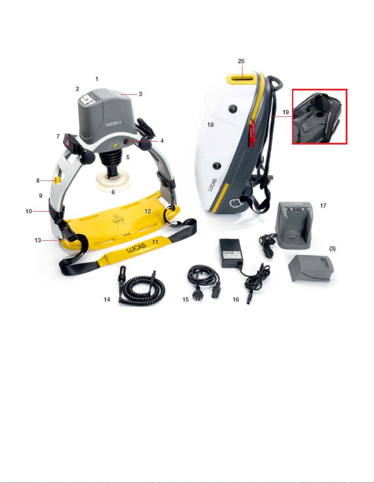
LUCAS® 3 Components ................................................................................................................................................. 9
Control Panel ................................................................................................................................................................ 10
Electronics Block Diagram ............................................................................................................................................ 11
Compression Mechanism ............................................................................................................................................. 12
Device Communication ................................................................................................................................................. 13
LUCAS® 3 Program Loader ............................................................................................................................................. 13
Software installation ..................................................................................................................................................... 13
Connect the device via Bluetooth ................................................................................................................................. 15
Connect the device via USB cable ............................................................................................................................... 19
View Error Code ........................................................................................................................................................... 22
Set Device S/N, Date, and Data ................................................................................................................................... 25
Change Device S/N ...................................................................................................................................................... 26
Set Latest Service Date ................................................................................................................................................ 26
Store View .................................................................................................................................................................... 26
Checksum ..................................................................................................................................................................... 27
Update LUCAS Software .............................................................................................................................................. 28
Calibrate Linear Sensor ................................................................................................................................................ 29
Failed calibration .......................................................................................................................................................... 31
Update LUCAS 3 sw 3.0 to LUCAS 3 sw 3.1 ............................................................................................................... 32
Setup ............................................................................................................................................................................ 32
Update and Test procedure .......................................................................................................................................... 33
Setup Options - LUCAS 3 Version 3.1 (Part No: 250041-00) ................................................................................... 35
Troubleshooting ............................................................................................................................................................... 39
Troubleshooting Table .................................................................................................................................................. 39
LUCAS Malfunction Alarm ............................................................................................................................................ 40
Error Codes .................................................................................................................................................................. 41
LUCAS® 3 Chest Compression System – Service Manual
3328798-002, ©2017 Physio-Control, Inc.
Page 2 of 91
Page 3

Error Codes from Control CPU ..................................................................................................................................... 42
Warnings from Control CPU ......................................................................................................................................... 45
Error Codes from Protective CPU ................................................................................................................................ 48
Error Codes from Charger CPU ................................................................................................................................... 49
User Errors ................................................................................................................................................................... 50
Bluetooth Connection Error .......................................................................................................................................... 50
Troubleshooting Tips .................................................................................................................................................... 51
Spare Parts and Accessories ........................................................................................................................................... 51
Spare Parts ................................................................................................................................................................... 51
Other Orderable Spare Parts........................................................................................................................................ 52
Accessories .................................................................................................................................................................. 54
Tools ................................................................................................................................................................................. 54
Standard Tools ............................................................................................................................................................. 54
Special Tools ................................................................................................................................................................ 55
Substances ................................................................................................................................................................... 55
Software ........................................................................................................................................................................ 55
Preventive Maintenance ................................................................................................................................................... 56
Maintenance Procedure ............................................................................................................................................... 56
Clean Electric Fan and Mesh Grill ................................................................................................................................ 57
Compression Module Lubrication ................................................................................................................................. 57
Claw Lock Lubrication .................................................................................................................................................. 58
Replacing Parts or Modules in LUCAS ............................................................................................................................ 58
How to Apply Thread Lock Fluid .................................................................................................................................. 58
How to Replace the Hood ............................................................................................................................................. 58
How to Replace the Bellows ......................................................................................................................................... 60
How to Replace the Compression Module ................................................................................................................... 62
How to Replace the Drive Belt...................................................................................................................................... 66
How to Replace the Electric Motor ............................................................................................................................... 67
How to Replace the Control PCBA ............................................................................................................................... 69
How to Replace the Protective PCBA .......................................................................................................................... 70
How to Replace the Electric Fan .................................................................................................................................. 71
How to Replace the Support Leg.................................................................................................................................. 73
How to Replace the Antenna ........................................................................................................................................ 80
How to Replace the Communication PCB .................................................................................................................... 82
Replacing the Power Inlet ............................................................................................................................................. 84
Replacing the Main Body/Frame Assembly ................................................................................................................. 86
Function Check ................................................................................................................................................................ 87
Introduction ................................................................................................................................................................... 87
Mechanics Test ............................................................................................................................................................ 87
Electronics Test ............................................................................................................................................................ 88
Accessories ...................................................................................................................................................................... 89
LUCAS Battery Charger ............................................................................................................................................... 89
LUCAS® 3 Chest Compression System – Service Manual
3328798-002, ©2017 Physio-Control, Inc.
Page 3 of 91
Page 4

LUCAS Car Cable ........................................................................................................................................................ 89
LUCAS Power Supply .................................................................................................................................................. 90
Appendix A (wiring diagram) ........................................................................................................................................ 91
LUCAS® 3 Chest Compression System – Service Manual
3328798-002, ©2017 Physio-Control, Inc.
Page 4 of 91
Page 5

Preface
This Manual describes how to maintain, test, troubleshoot, and repair the LUCAS® 3.
Another publication, the LUCAS
clinicians, and emergency care providers. The IFU provides step-by-step instructions for use, as well as operator-level
testing and maintenance.
Disclaimer
Physio-Control does not accept liability for injury to personnel or damage to equipment that may result from misuse of
LUCAS. Under no circumstances shall Physio-Control be liable for incidental or consequential damage arising from the
use of LUCAS.
All discovered failures that directly or indirectly have, or may have, affected patient or user safety shall, with no delay,
be reported directly to the Quality Department at Physio-Control, Inc.
All the screenshots or pictures in this document are for the example only; they are subject to change without matching
the latest versions of software.
Trademarks
LUCAS® 3 is a trademark of Jolife AB. LUCAS 3 Report Generator is a trademark of Physio-Control, Inc. Microsoft and
Windows are registered trademarks of Microsoft Corporation in the US and/or other countries. Specifications are
subject to change without notice.
®
3 Chest Compression System - Instruction for Use (IFU) is for physicians,
Definitions, Acronyms, and Abbrevia ti ons
IFU Instructions for Use, LUCAS 3, PNs/CAT #: 3326785-0## / 26500-00####
Instructions for Use, LUCAS 3 Version 3.1, PNs/CAT #: 3326785-1## /
26500-00####
LRG LUCAS® 3 Report Generator, a data download Software
DT Express Data Transfer Express
FSR Field Service Representative (services products in the Field)
LUCAS LUCAS® 3 Chest Compression System
LIFENET LIFENET System including website
Nm Unit for torque value in Newton Meter
PCO file
Physio Case Object file, a data format for a combination of device data and
user-entered data. Data in this format can be imported and exported by
Physio-Control data management applications.
PIP Performance Inspection Procedure
SmartDesk LIFENET connectivity support
LUCAS® 3 Chest Compression System – Service Manual
3328798-002, ©2017 Physio-Control, Inc.
Page 5 of 91
Page 6

Contacting Physic-Control
Stryker South Pacific
MANUFACTURER
Fax. +46 46 286 50 10
Physio-Control, Inc.
11811 Willows Road NE
Redmond, WA 98052-2003 USA
Telephone: 425.867.4000
Toll Free (USA only): 800.442.1142
Fax: 800.426.8049
Internet: www.physio-control.com
Stryker European Operations B.V.
Herikerbergweg 110, 1101 CM
Amsterdam, The Netherlands
Tel: +31 (0)20 2192600
Fax: +31 (0)20 2192703
8 Herbert Street
St Leonards, NSW 2065
Australia
Tel: +61 (0)2 94671000
Jolife AB
Scheelevagen 17
Ideon Science Park
SE-223 70 LUND
Sweden
Tel. +46 46 286 50 00
Service Personnel Qualification
Service personnel must be properly qualified and trained, and thoroughly familiar with the operation of the LUCAS® 3.
They must meet at least one of the following requirements (or the equivalent):
• Physio-Control Service Depot technicians
• Physio-Control Field Service Representatives
rd
Party Service Providers that have service agreements with Ph ysio-Control
• 3
Service Information
Before attempting to clean or repair any assembly in the device, the Service personnel should be familiar with the
information provided in Pre ven ti ve Ma inte nance .
A qualified Technic al Supp or t s hou ld inspec t any device that has been dropped, damaged, or abused to verify that the
device is operating within performance standards listed in the Performance Inspection Procedures (PIP).
Replacement procedures for the device are limited to those items accessible at the final assembly level. Replacements
and adjustments must be made by qualified service personnel. Replacements at the final assembly level simplify repair
and servicing procedures and help ensure correct device operation and calibration.
To obtain service and maintenance for your device, contact your local Physio-Control service or sales representative.
In the USA, call Physio-Control Technical Support at 1.800.442.1142. Outside the USA, contact your local PhysioControl representative.
When you call Physio-Control to request service, provide the following information:
• Model number and part number
• Serial number
• Observation of the problem that led to the call
LUCAS® 3 Chest Compression System – Service Manual
3328798-002, ©2017 Physio-Control, Inc.
Page 6 of 91
Page 7

Configuration Inf orm a ti on
Item Number
Catalog Number
Description
This service manual covers the LUCAS® 3 also known as LUCAS in this manual.
Unless otherwise noted, functions and features are consistent as specified throughout this manual. Differences are
noted as appropriate.
3326785-0## 99576-0000## LUCAS 3, *
3326785-0## 99576-0000## LUCAS 3 version 3.1, *
Note:
# in the dash number of Item Number and Catalog Number is different for each language specification.
* Description contains country specification.
Device Tracking
All performed service where modules are replaced, the serial no./batch no. of each module shall be stated in the
service report. This information is then sent to Physio-Control, Inc., on a monthly basis.
The modules that have traceability are:
• Compression Module
• Electronic PCBs
• Electric Motor
• Battery
• Main Body
• Support Leg
• Hood
• Back plate
Recycling Information
Important!
The Battery used in LUCAS shall be returned to the local recycling station or dealer/distributor for correct recycling.
LUCAS contains of several materials as listed below:
• Polyphthalamide (PPA) with 50% glass fiber
• Polyamide reinforced with 30% glass fiber
• Polycarbonate/Polybutylene Terephthalate
• Polycarbonate
• Polyurethane
• PVC
• POM
• Silicone
• Chloroprene
• Aluminum
• Stainless steel
• Brass
For further recycling information please contact Jolife AB, Sweden.
LUCAS® 3 Chest Compression System – Service Manual
3328798-002, ©2017 Physio-Control, Inc.
Page 7 of 91
Page 8

Warnings and Precautions
Except the warnings stated below, there are also warnings and precautions mentioned in the following documents that
are of relevance during service and maintenance of LUCAS.
LUCAS
LUCAS®3 Version 3.1 Chest Compression System - Instruction for Use (PNs/CAT #: 3326785-1## / 26500-00####)
®
3 Chest Compression S ystem - Instruction for Use (PNs/CAT #: 3326785-0## / 26500-00####)
• Electrical Hazard
Use caution when examining or operating the device without its covers.
• Chemical Hazard
The Battery contains chemicals, in case of leakage use extreme caution to avoid injuries. Never try to open the
casing of the Battery.
• ESD Protection
Always use ESD protection when handling electronic boards and connections.
Warranty
To obtain a detailed warranty statement, contact your local Physio-Control representative or go to www.physio-
control.com
LUCAS® 3 Chest Compression System – Service Manual
3328798-002, ©2017 Physio-Control, Inc.
Page 8 of 91
Page 9
Device Information
LUCAS® 3 Components
LUCAS® 3 Chest Compression System – Service Manual
3328798-002, ©2017 Physio-Control, Inc.
Page 9 of 91
Page 10

TRANSMIT
DATA
ACTIVE
ACTIVE (30:2)
Bluetooth LED
WiFi LED
Power ON/OFF
ADJUST
PAUSE
MUTE
Battery Indicator
WARNING
LUCAS has two Support Legs that lock to the Back Plate with Claw Locks. The Support Legs are foldable for
convenient transportation.
The Claw Locks automatically lock to the Back Plate when LUCAS is pressed on to it. To unlock the Claw Locks, pull
the Release Rings
Control Panel
The User Control Panel is the user interface with which the device can be controlled and monitored through seven
button switches and a number of LED’s. The User Control Panel is situated on the hood and is connected to the
protective/charger system that sends the signals to the control system. For further details on the User Control Panel
please read chapter 2.7 in the Instructions for Use which also explains the different states on the Battery indicator.
LED
(continuous)
LUCAS® 3 Chest Compression System – Service Manual
3328798-002, ©2017 Physio-Control, Inc.
Page 10 of 91
Page 11
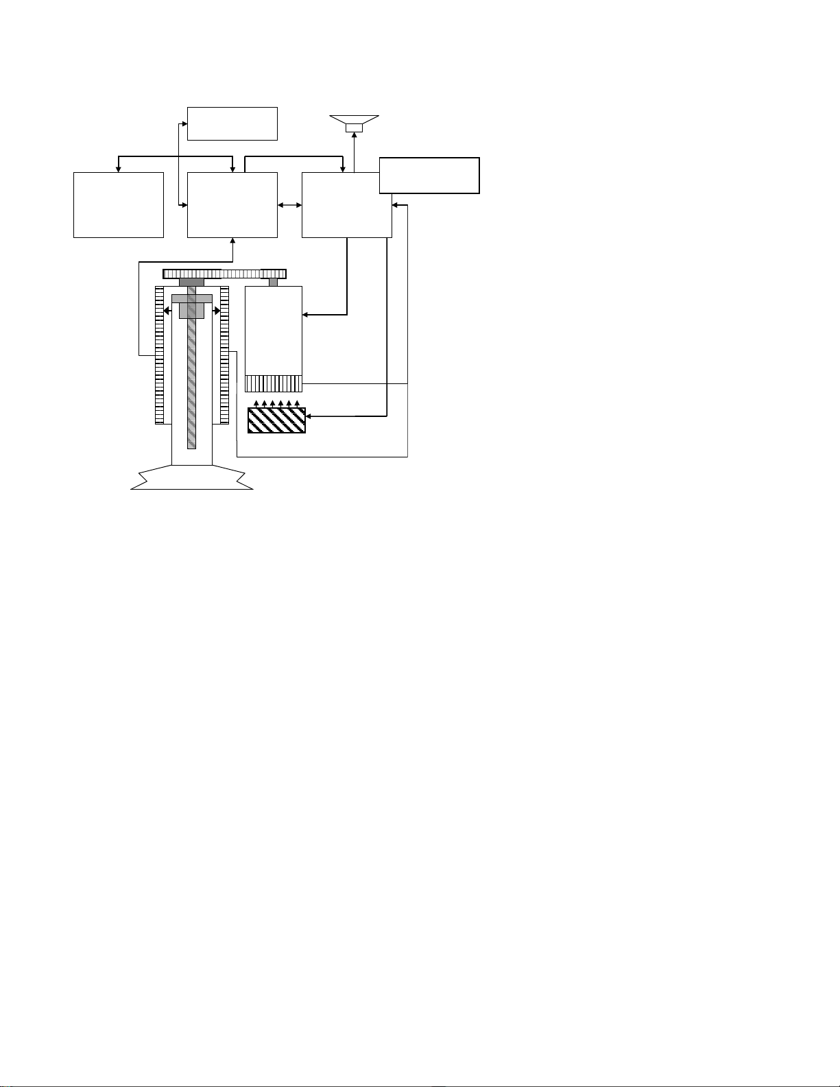
Electronics Block Diagram
Control
PCB
Protective &
Charger
PCB
Battery
User Control
Panel
Electric
Motor
Rotation Sensor
Linear Sensor 2
Linear
Sensor 1
Power
Power
Power
Fan
Speaker
Communication
PCB
LUCAS is driven by a rechargeable Lithium Ion Polymer (LiPo) Battery. The Battery can be charged during operation
by an external Power Supply, connected to a wall outlet, or with a Car Power Cable. You can also remove the Battery
from LUCAS and recharge it in a separately sold Battery Charger of desktop model.
NOTE: The Battery must be connected even when the device is supplied by the power supply.
The Battery is mechanically keyed in LUCAS and in the Battery Charger to make sure you get the correct installation.
The top of the Battery has connections for power and communication to the Battery Charger and to LUCAS.
The Battery has built in intelligence to monitor the number of usage cycles and battery age to tell the user when to
replace the Battery. It also monitors the internal temperature of the Battery.
The Battery supplies the electronics and the electrical Motor. The Motor is connected to the linear unit via a drive belt.
The electronics is divided in four parts but situated on three separate PCB’s:
1. The Control System that controls the motor with information from the user interface and from the rotation and
linear sensors.
2. The Communication System that sends data wirelessly via Bluetooth and WiFi to/from computer.
3. The Protective System that controls inputs and outputs and shut off in case of a problem. The internal Battery
Charger that controls the charging sequence of the Battery.
There are two separate linear measuring sensors that monitor the movement of the Suction Cup:
1. Linear sensor 1 is for the Control System,
2. Linear sensor 2 works as a reference to the Protective System.
An electrical fan is situated at the bottom of the device for cooling the electrical motor and other electronics, the fan
starts when the internal temperature reaches 40°C and stops when the temperature is below 30°C
LUCAS® 3 Chest Compression System – Service Manual
3328798-002, ©2017 Physio-Control, Inc.
Page 11 of 91
Page 12
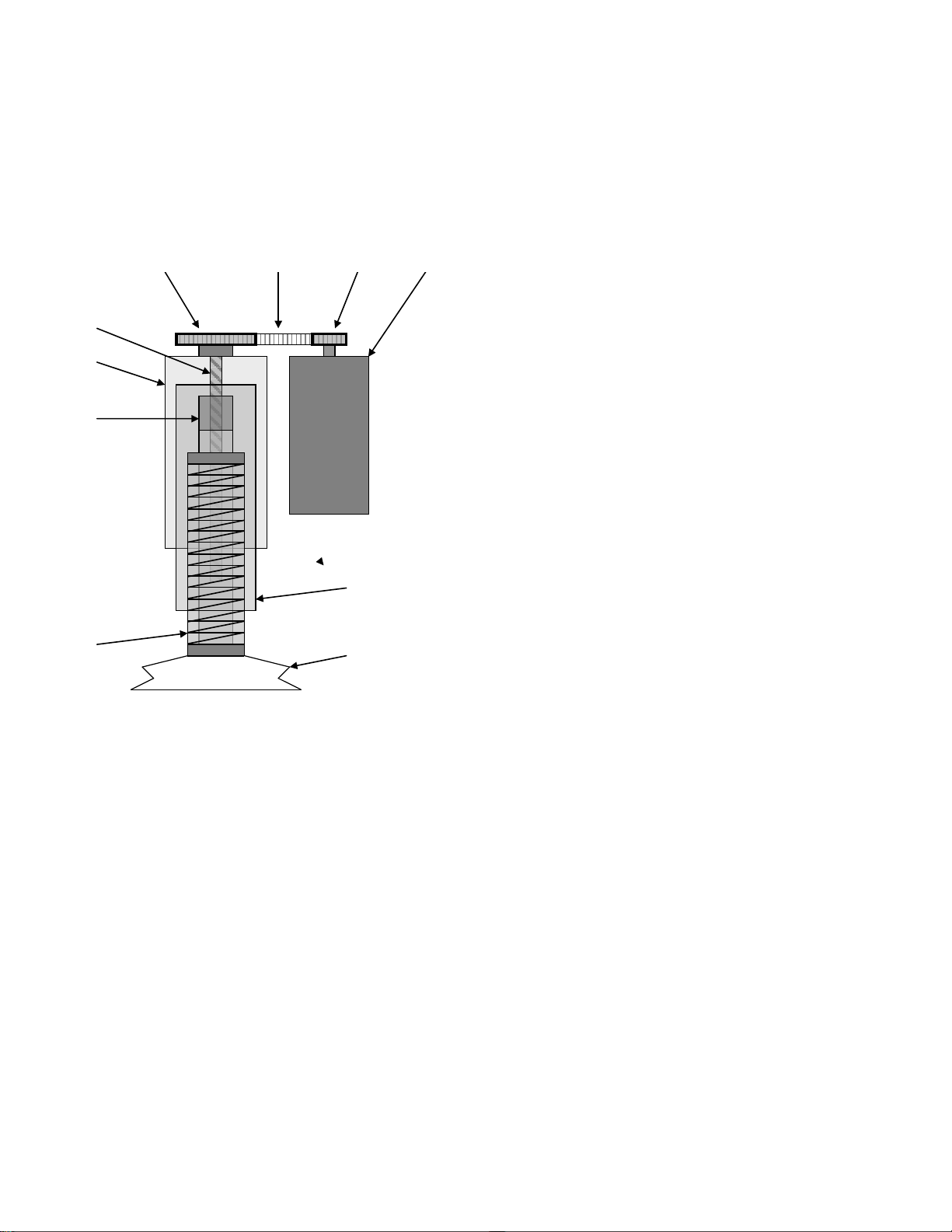
Compression Mechanism
1. Belt Wheel Large
2. Drive Belt
3. Belt Wheel Small
4. Electric Motor
5. Carry Ball Screw
6. Outer Tube
7. Carry Ball Nut
8. Decompression
Spring
9. Adjustment tube
10. Suction Cup
5
6
7
8
9
10
The Drive Belt, driven by the electrical Motor, drives the Carry Ball Screw forcing the Carry Ball Nut up and down.
The Carry Ball Nut is fitted to a piston that moves the suction cup piston up and down.
The Decompression Spring reduces the upstroke force.
The Suction Cup is adjusted to the patients’ chest with a servo aid system. The suction cup can easily be replaced
with respect to hygiene.
LUCAS® 3 Chest Compression System – Service Manual
3328798-002, ©2017 Physio-Control, Inc.
Page 12 of 91
Page 13
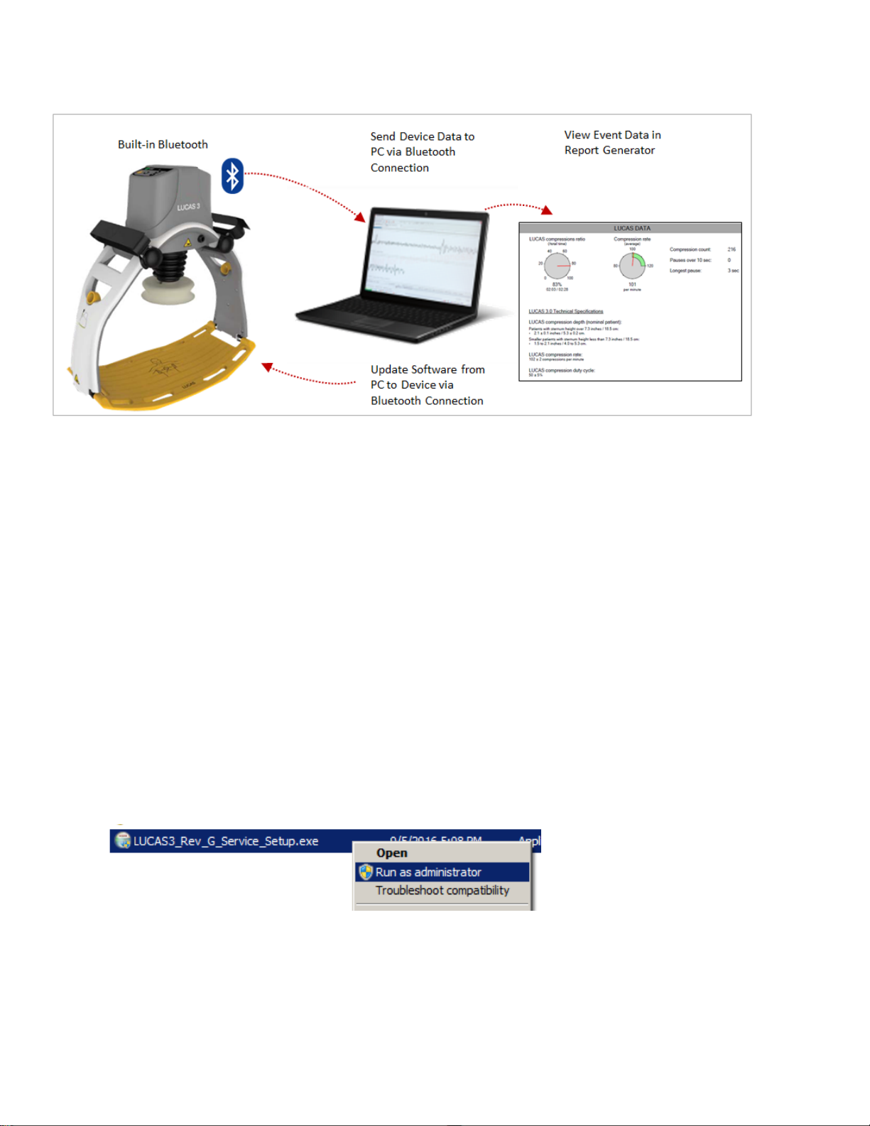
Device Communicati on
LUCAS
®
3 has a built-in communication board with Bluetooth or WiFi connection, it allows:
1. Post-event data being download to the PC without opening the hood, and view Event Data in the Report
Generator after data download.
2. WiFi with LIFENET connectivity.
3. Setup Options configurable via LIFENET through WiFi or with the LUCAS
4. Using LUCAS
device log, and perform sensor calibration.
®
3 Program Loader with Bluetooth connection to update Software from PC to Device, view
®
3 Program Loader.
LUCAS® 3 Program Loader
LUCAS® 3 program loader is software for updating the program and change the Setup options in LUCAS. It can also
be used to read errors and warnings from the device, and perform the sensor calibration. This section explains how the
software works.
• LUCAS 3 Program Loader should only be used by trained personnel
• Antivirus protection and fire walls shou ld be installed on the computer that have the LUCAS 3 Program Loader
installed.
• All suspected cyber security threats shall be reported to Physio-Control.
Software installation
To install LUCAS 3 Program Loader version 3.x:
1. Right Click on LUCAS3_V3X_RevX_Service_Setup.exe, and Run as administrator
2. Installation starts
3. Click on Next from this screen:
LUCAS® 3 Chest Compression System – Service Manual
3328798-002, ©2017 Physio-Control, Inc.
Page 13 of 91
Page 14
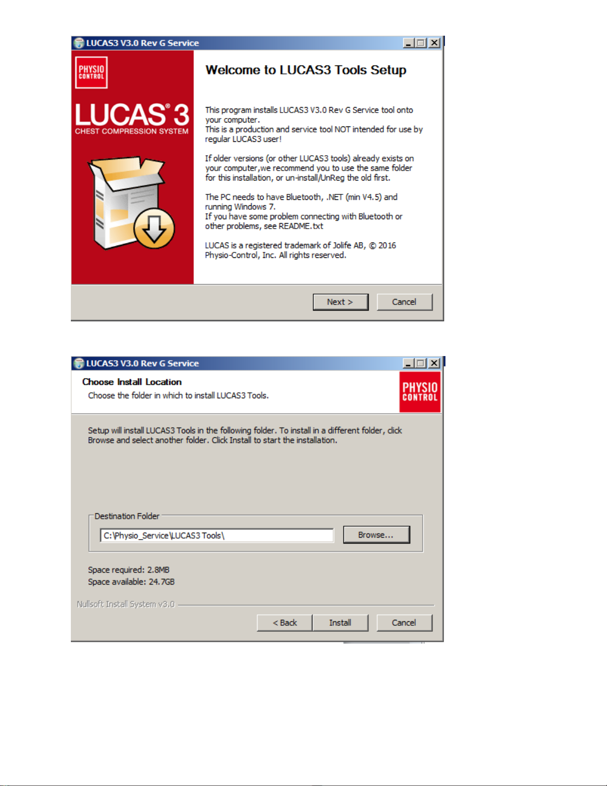
(Visual differences in screen interface may occur for different software versions.)
4. Choose installation location on PC, and Click Install
5. Click Finish to add the shortcut on the Desktop
LUCAS® 3 Chest Compression System – Service Manual
3328798-002, ©2017 Physio-Control, Inc.
Page 14 of 91
Page 15
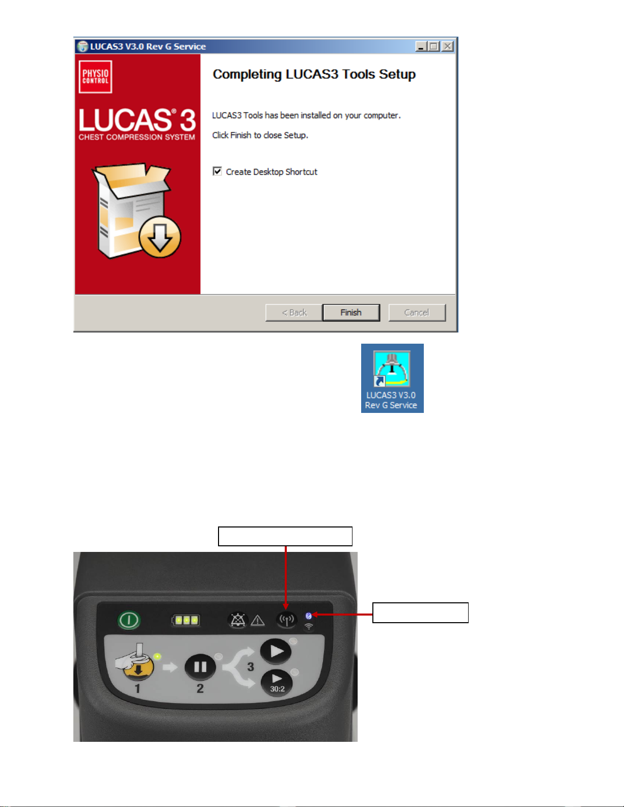
Bluetooth symbol
TRANSMIT DATA button TRANSMIT DATA button
6. Test LUCAS 3 Program Loader by double click on desktop icon
(Note. Different software versions can occur)
Connect the device via Bl ue t oot h
When updating the program in LUCAS using the Bluetooth connection, there is no need to open the hood.
1. Ensure the LUCAS Device is powered OFF and no LEDs are on.
2. Press and hold TRANSMIT DATA button for one second to turn on Bluetooth mode, ensuring the Bluetooth
symbol lights up and flashing.
LUCAS® 3 Chest Compression System – Service Manual
3328798-002, ©2017 Physio-Control, Inc.
Page 15 of 91
Page 16
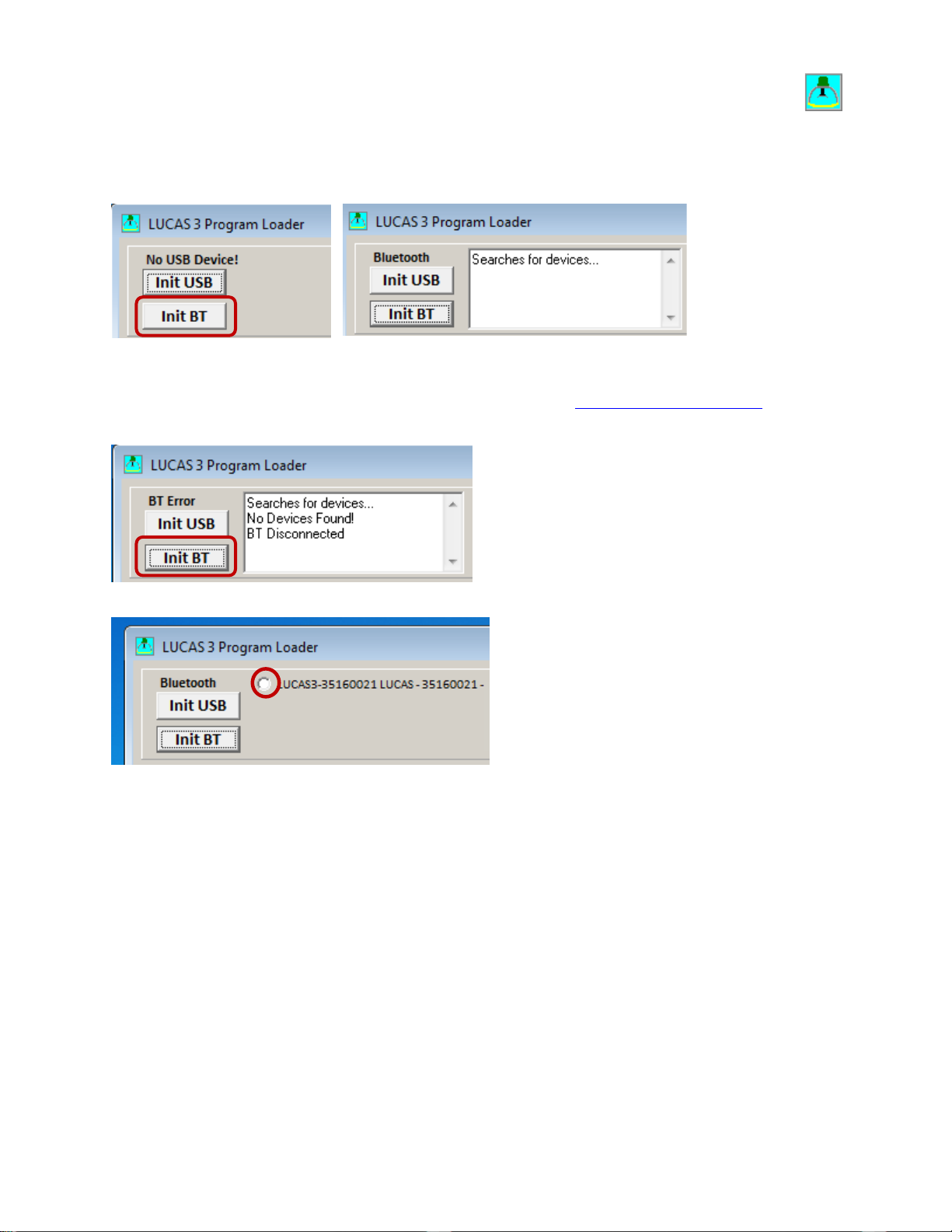
3. Start the LUCAS 3 Program Loader sof t ware by exec ut ing LUCAS3_V3_X_REV_X_Service.exe file,
.
(Note. Different software versions can occur)
4. Click Init BT to connect PC to LUCAS 3 device via Bluetooth, and Wait for Program Loader to search for
LUCAS 3 device…
5. If No Devices Found message displayed, click Init BT and try again. Note: It may take up to 30 seconds for
the LUCAS 3 communication app to boot up. You may have to click Init BT 2 ~ 3 times before LUCAS device
shows up on the screen. If “BT Error” occurred repeatedly, refer to Bluetooth Connection Error
in
troubleshooting chapter.
6. When Program Loader found LUCAS 3, select the LUCAS that shall be connected.
7. When Bluetooth connection is established, the Program Loader screen will show CPUs information shown as
following pictures.
LUCAS® 3 Chest Compression System – Service Manual
3328798-002, ©2017 Physio-Control, Inc.
Page 16 of 91
Page 17
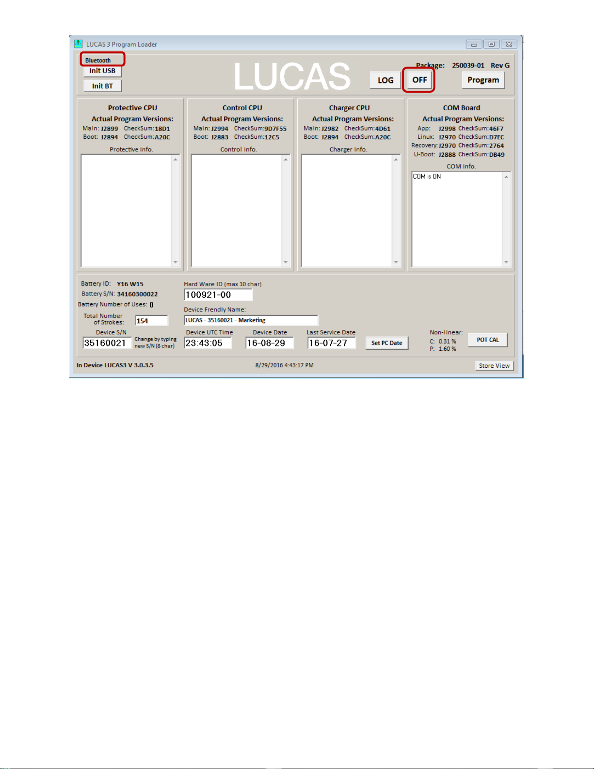
- Picture shows connection via Bluetooth for LUCAS 3 Version 3.0 (Part No: 250039-00)
Note, differences in J-numbers and CheckSum Numbers may occur due to different program versio ns –
• Check that the serial number (S/N) in the Device S/N window is equal as the S/N number on the device type
label
LUCAS® 3 Chest Compression System – Service Manual
3328798-002, ©2017 Physio-Control, Inc.
Page 17 of 91
Page 18
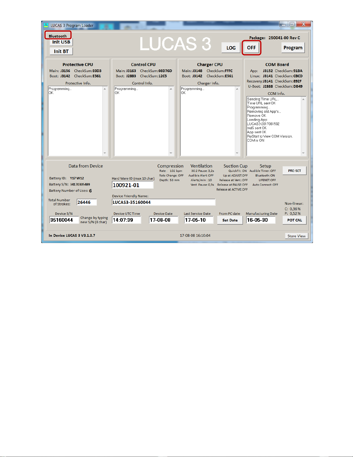
- Picture shows connection via Bluetooth for LUCAS 3 Version 3.1 (Part No: 250041-00)
Note, differences in J-numbers and CheckSum Numbers may occur due to different program versions –
• Check that the serial number (S/N) in the Device S/N window is equal as the S/N number on the device type
label
8. To disconnect Bluetooth connection, click on OFF button. The Bluetooth symbol light will go off.
LUCAS® 3 Chest Compression System – Service Manual
3328798-002, ©2017 Physio-Control, Inc.
Page 18 of 91
Page 19
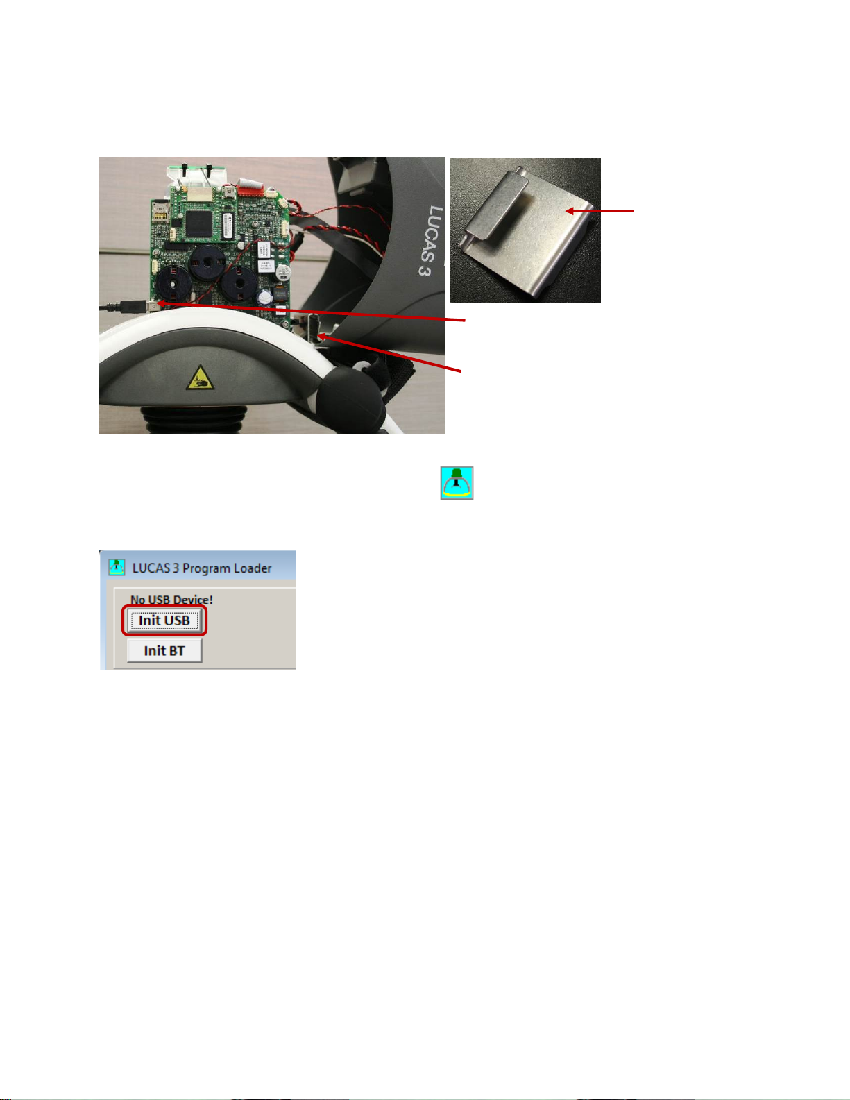
Connect the device via USB cable
Hood Holder Bracket
USB Port Location
Hood Holder Bracket Location
1. Remove the hood according to Disassembling instruction in How to Replace the Hood, and use the Hood
Holder bracket to hold the hood on the side and the battery should be installed.
2. Connect an USB cable between the computer and the device, the connector is situated at the lower left side of
the Control PCB.
3. Start the device
4. Start the software by executing LUCAS3_V3_0.exe file,
(Note. Different software versions might occur)
5. Normally the software detects the device at start. If not, then Click Init USB.
6. When USB connection is established, the Program Loader screen will show CPUs information
.
LUCAS® 3 Chest Compression System – Service Manual
3328798-002, ©2017 Physio-Control, Inc.
Page 19 of 91
Page 20
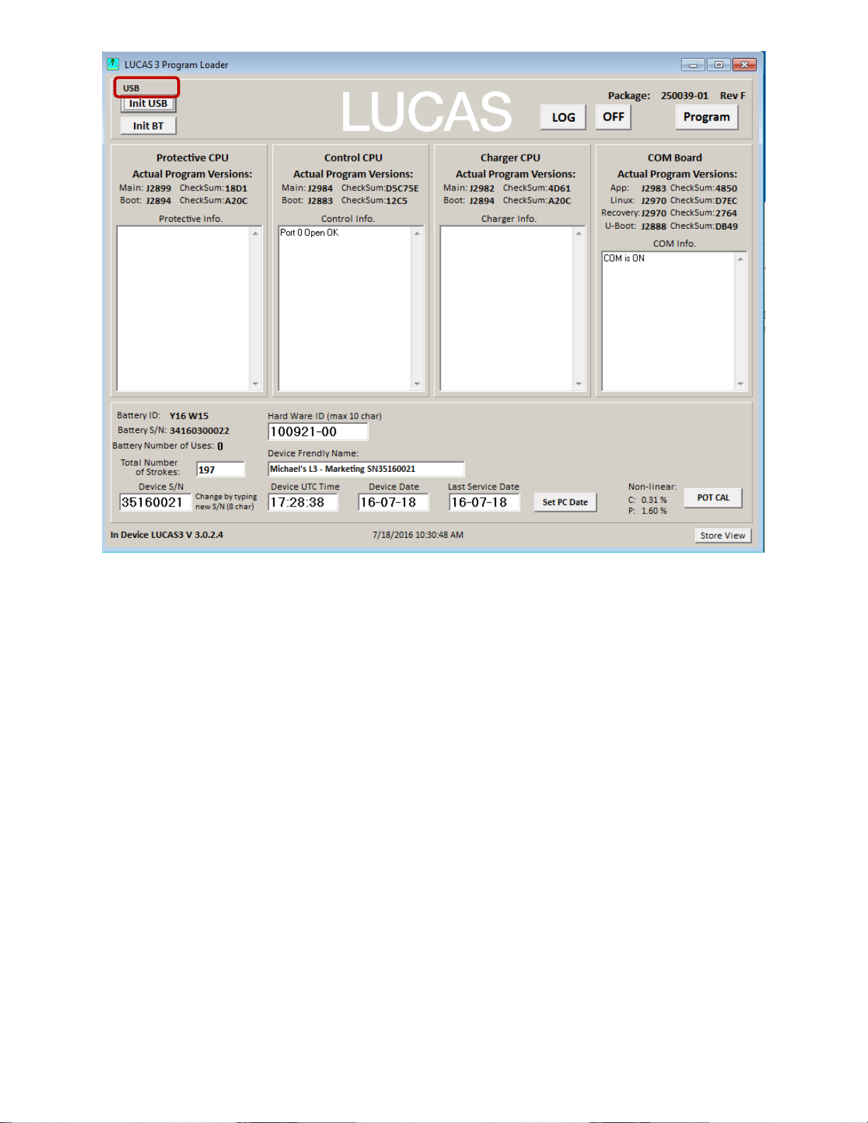
- Picture shows connection via USB cable for LUCAS 3 Version 3.0 (Part No: 250039-00)
Note, differences in J-numbers and CheckSum Numbers may occur due to different program versio ns –
LUCAS® 3 Chest Compression System – Service Manual
3328798-002, ©2017 Physio-Control, Inc.
Page 20 of 91
Page 21
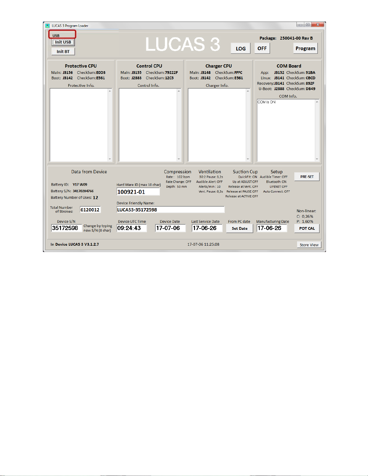
- Picture shows connection via USB cable for LUCAS 3 Version 3.1 (Part No: 250041-00)
Note, differences in J-numbers and CheckSum Numbers may occur due to different program versions –
LUCAS® 3 Chest Compression System – Service Manual
3328798-002, ©2017 Physio-Control, Inc.
Page 21 of 91
Page 22
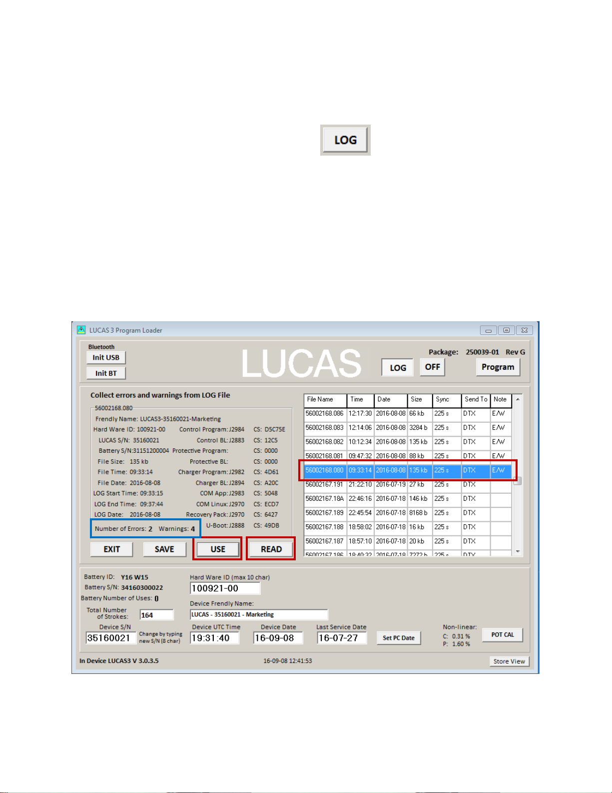
View Error Code
3.
2.
1.
Once the connection is made from Bluetooth or USB cable, the information about the device should appear in the
designated CPU windows.
The device Errors and Warnings will appear in each CPU’s box window.
To view existing log information on the device, click LOG button,
Highlight a row
• Press READ to view log data
• Press USE to see the Error and Warnings code in different CPU windows
• Press SAVE to save the raw log file data to PC (only for developers to use)
• Press EXIT to exit LOG view
Example:
1. Highlight a row according to Date and Time the error occurred from LOG view;
2. Click READ and wait to see the “Collect errors and warnings from LOG File” to show up on the left side of
window;
3. If the Number of Errors or Warnings are not 0, Click USE to see the highlighted LOG Error code in the CPU
windows (USE will exit LOG view also).
, Log view shows log data on screen.
- Picture shows LOG File content on the left for LUCA S 3 Version 3.0 (Part No: 250039-00)
Note, differences in J-numbers and CheckSum Numbers may occur due to different program versions –
LUCAS® 3 Chest Compression System – Service Manual
3328798-002, ©2017 Physio-Control, Inc.
Page 22 of 91
Page 23
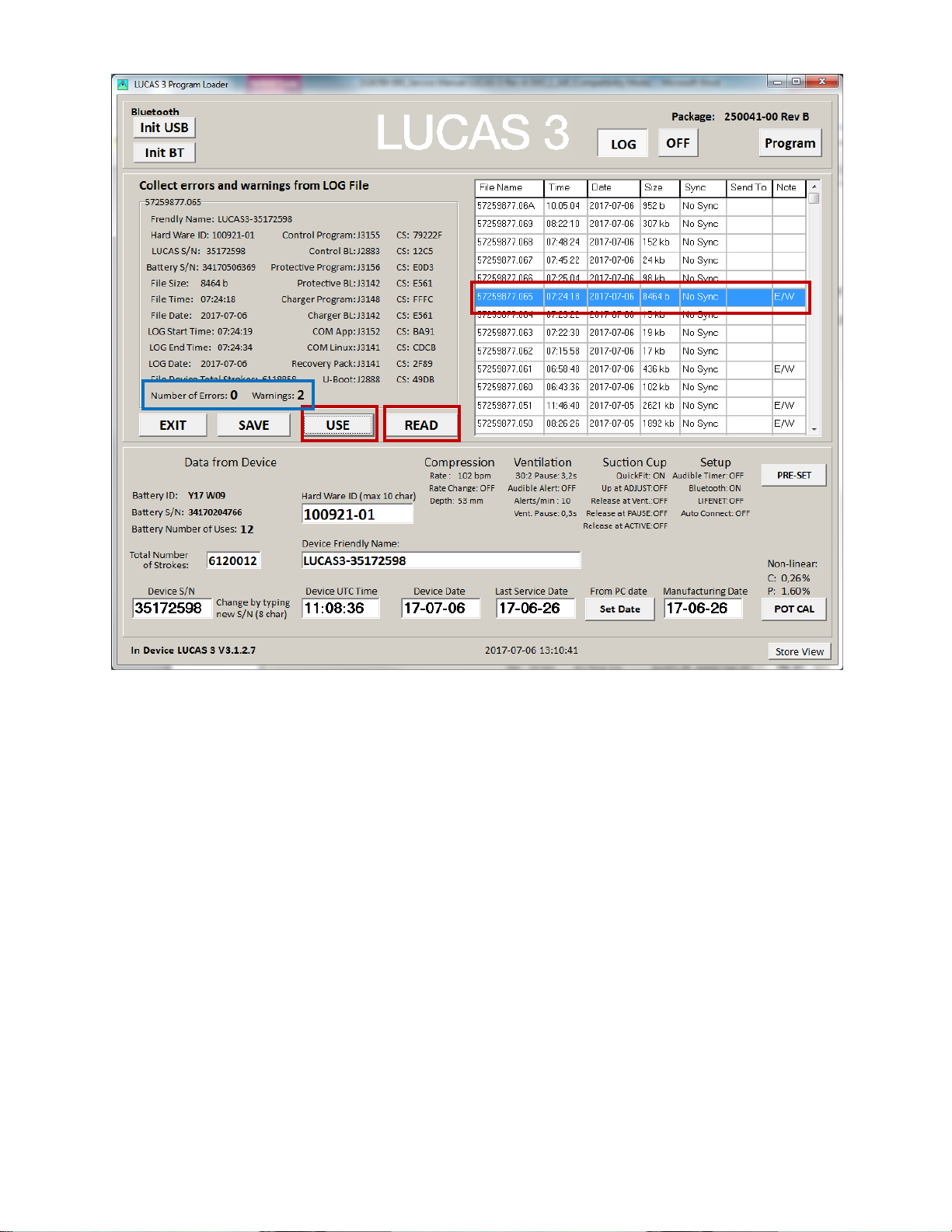
3.
2.
1.
- Picture shows LOG File content on the left for LUCAS 3 Version 3.1 (Part No: 250041-00)
Note, differences in J-numbers and CheckSum Numbers may occur due to different program versions –
LUCAS® 3 Chest Compression System – Service Manual
3328798-002, ©2017 Physio-Control, Inc.
Page 23 of 91
Page 24
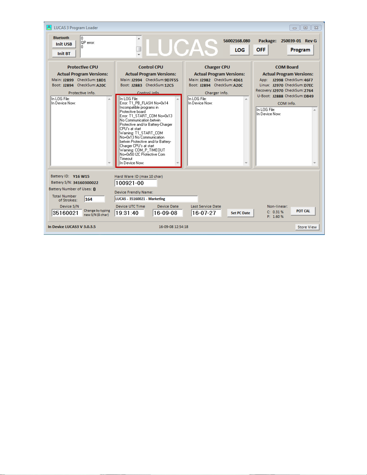
- Picture shows Error Codes in CPU window for LUCAS 3 Versi o n 3.0 (Part No: 250039-00)
Note, differences in J-numbers and CheckSum Numbers may occur due to different program versions –
LUCAS® 3 Chest Compression System – Service Manual
3328798-002, ©2017 Physio-Control, Inc.
Page 24 of 91
Page 25
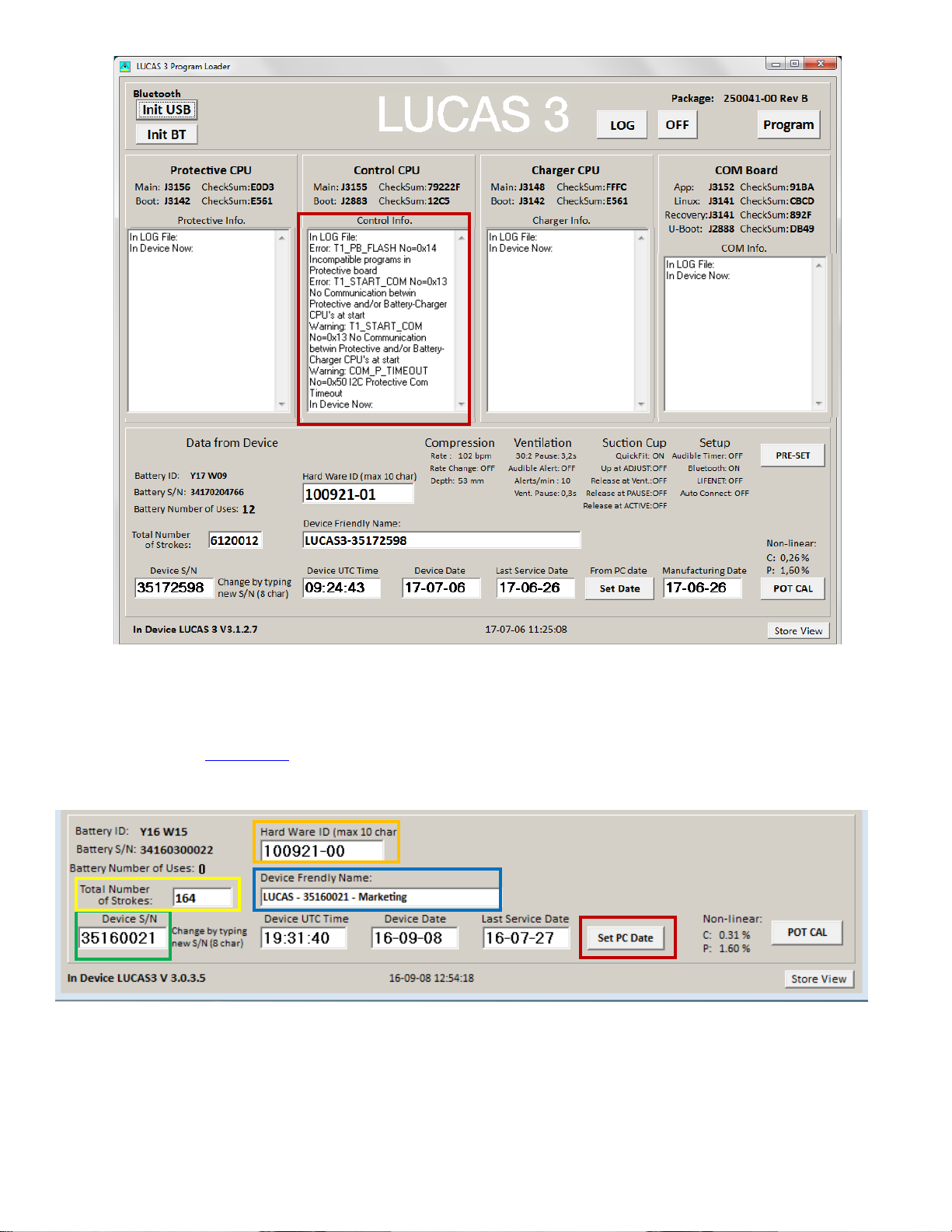
- Picture shows Error Codes in CPU window for LUCAS 3 Version 3.1 (Part No: 250041-00)
Note, differences in J-numbers and CheckSum Numbers may occur due to different program versions –
4. Then refer to Error Codes
Tables for more information about how to handle the errors.
Set Device S/N, Date, and Data
- LUCAS 3 Version 3.0 (Part No: 250039-00) –
LUCAS® 3 Chest Compression System – Service Manual
3328798-002, ©2017 Physio-Control, Inc.
Page 25 of 91
Page 26
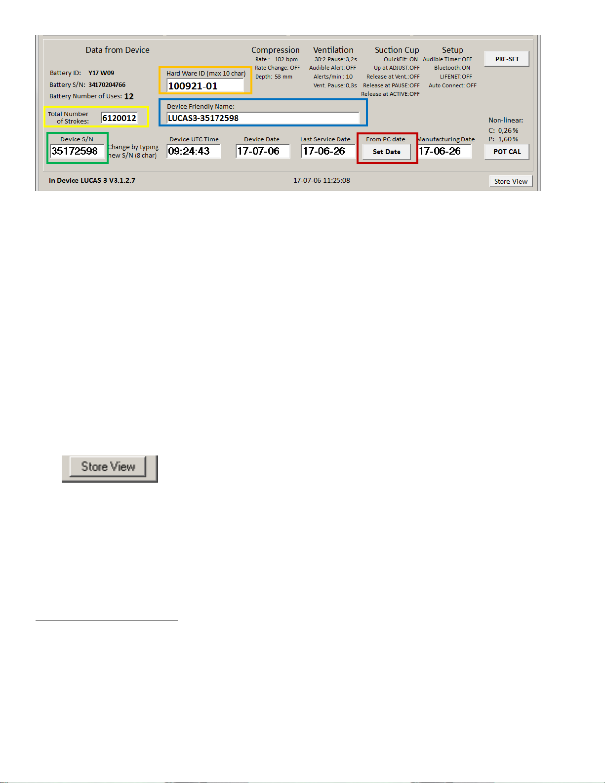
- LUCAS 3 Version 3.1 (Part No: 250041-00) –
-
It’s also possible to set the Device ID(S/N), Friendl y Name, Time and Last Service Date, and reset total number of
Strokes.
NOTE:
• When setting up Device Time, always use UTC-0 time
• Both Device Date and Last Service Date are in YY-MM-DD format
• Setup will be automatically saved to the device
Change Device S/N
The Device S/N (=Serial number of the device) can be set simply by typing in the wanted S/N (8 char), typically
3516XXXX. The S/N is automatically saved.
Set Latest Service Date
Set latest Service date by pressing SET PC Date / SET Date.
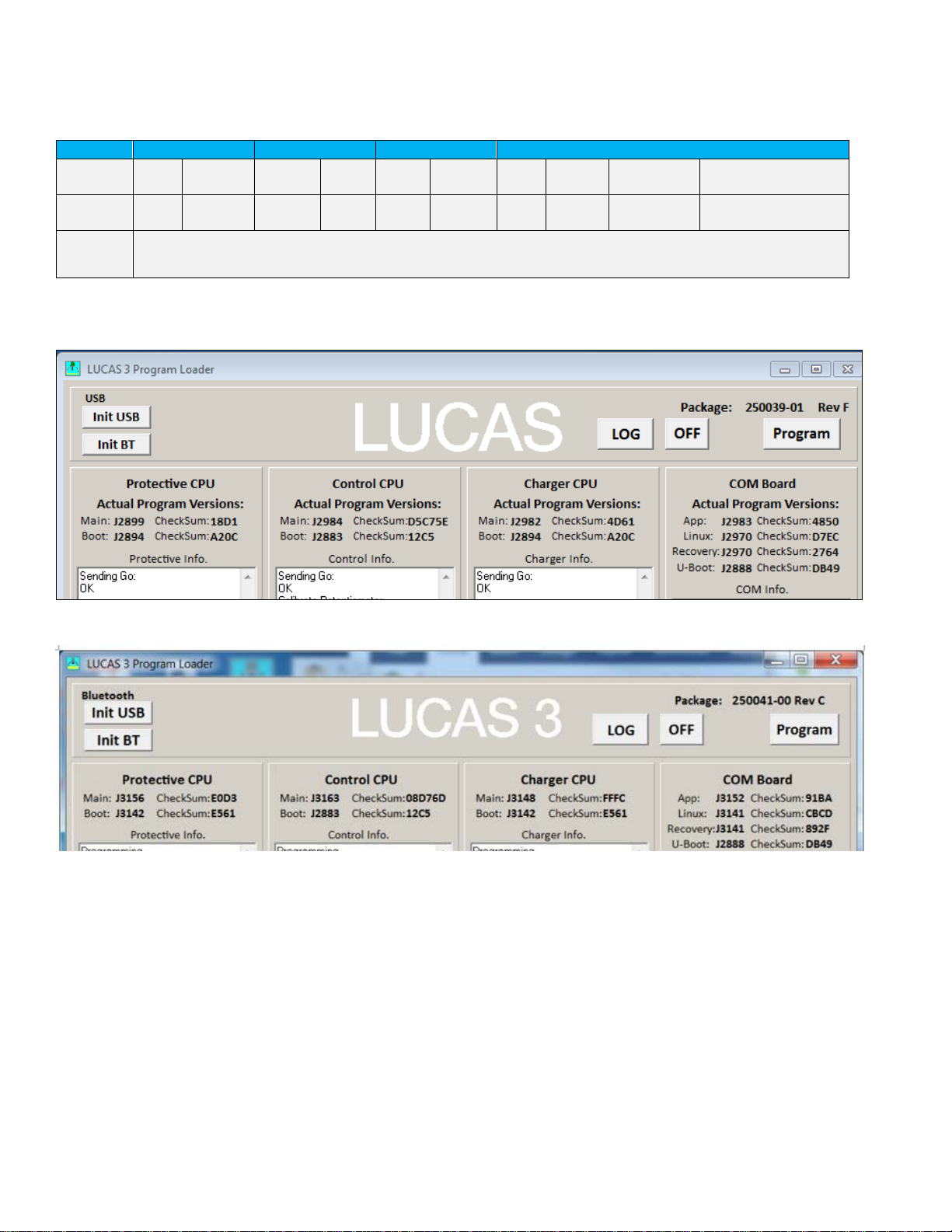
Store View
The Program Loader screenshot can be stored for future reference by clicking “Store View”.
The screenshot will be saved in a sub-folder “Pictures” where the Program Loader folder is with the serial number as
1
file name
. At the same time the screenshot will be printed at the selected default printer. If no printer is connected, a
message will appear which can be cancelled; the picture will be saved and can be printed at any time.
1
An administrative right to the ”LUCAS3 Tools” folder is necessary to save the screenshot. This can either be done by
right-clicking the LUCAS
®
3 program loader.exe file and chose “Run as administrator” every time you want a
screenshot saved to the “Pictures” subfolder or by locating the ”LUCAS3 Tools” folder on your computer, right-click the
folder, chose Properties, choose the Security tab, highlight your “Users” name, e.g. Users (ANRESN-L1\Users), click
Edit, chose your “Users” name again, then in the “Permissions for Users” window in the Allow column make sure that
the Write-box is marked, then chose Apply. This allows the program to save screenshots to the ”LUCAS3 Tools” folder
®
and subfolders without having to run the LUCAS
3 program loader.exe as Administrator.
LUCAS® 3 Chest Compression System – Service Manual
3328798-002, ©2017 Physio-Control, Inc.
Page 26 of 91
Page 27
Checksum
Protective
Control
Charger
COM CPU
Program
ver:
A20C or
E561
A20C or
E561
To identify the installed program version you can check the CheckSum values to match table below:
Main Boot Main Boot Main Boot App Linux Recovery U-Boot
3.0 18D1
3.1
Following picture shows the example where to see the CheckSum values on each CPU and COM Board fr om
Program Loader.
The Change Order Numbers and CheckSum Numbers are automatically checked by Program Loader
250041-00
9D7F55 12C5 4D61
- LUCAS 3 Version 3.0 (Part No: 250039-00) –
46F7 D7EC 2764 DB49
LUCAS® 3 Chest Compression System – Service Manual
3328798-002, ©2017 Physio-Control, Inc.
- LUCAS 3 Version 3.1 (Part No: 250041-00) –
Page 27 of 91
Page 28
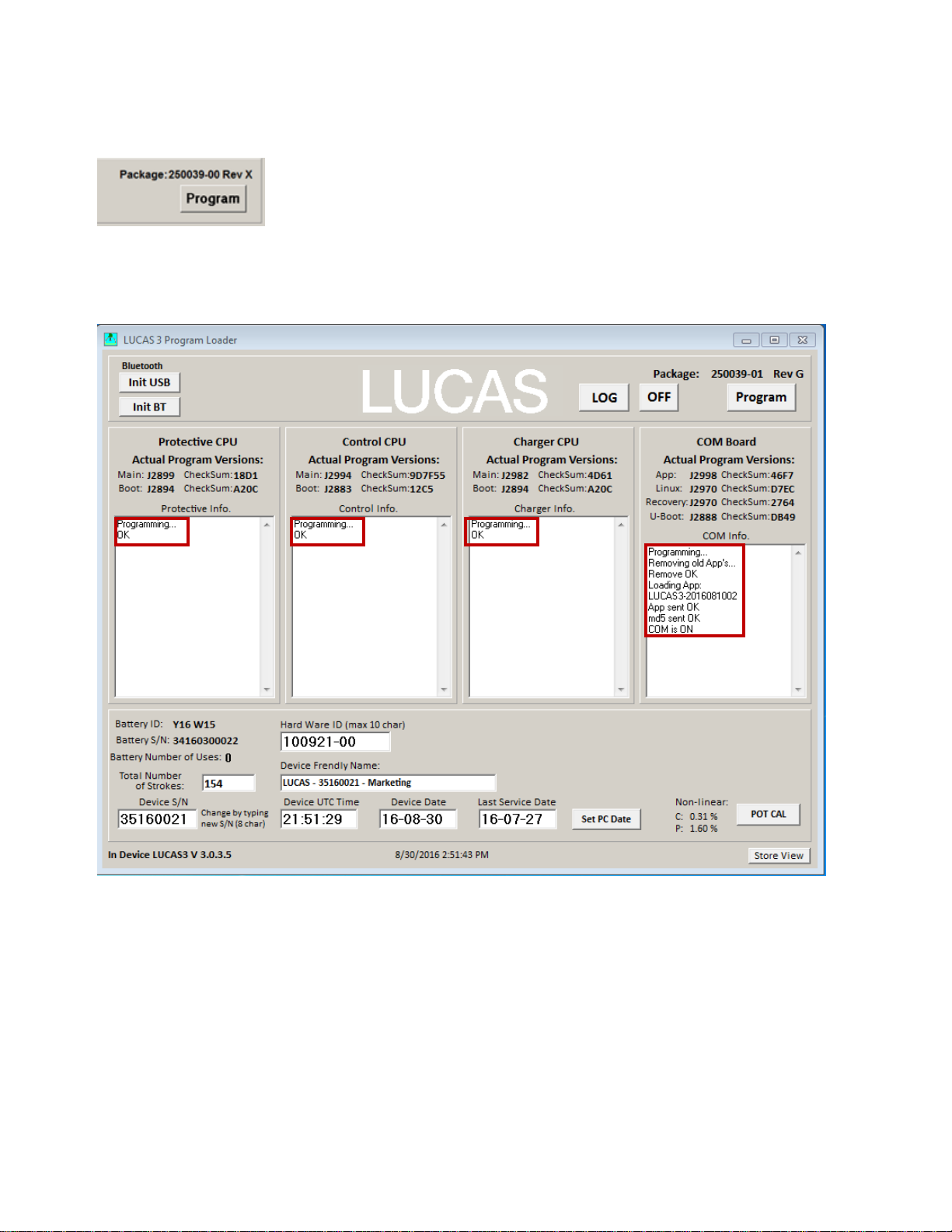
Update LUCAS Software
1. Click Program in the upper right corner to update LUCAS software.
The programming process will start and update the software for each CPU. Note: Do not disconnect the
connection during the software update. When all four CPUs are updated, following window will appear. Each
CPU window will have OK to indicate the update is complete.
- LUCAS 3 Version 3.0 (Part No: 250039-00) –
LUCAS® 3 Chest Compression System – Service Manual
3328798-002, ©2017 Physio-Control, Inc.
Page 28 of 91
Page 29

- LUCAS 3 Version 3.1 (Part No: 250041-00) –
Calibrate Linear Sensor
After software update is complete, Click POT CAL to calibr ate Li near Se ns or. Before you click the Start button please
make sure that nothing can influence the movement of the suction cup, that the device is in its upright position and
that the Suction Cup is approximately 20mm (~1 inch) down from its upmost position.
LUCAS® 3 Chest Compression System – Service Manual
3328798-002, ©2017 Physio-Control, Inc.
Page 29 of 91
Page 30
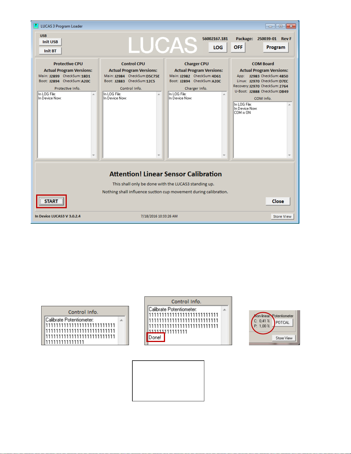
- Example LUCAS 3 Version 3.0 (Part No: 250039-00) –
POT CAL
- LUCAS 3 Version 3.1 (Part No: 250041-00) –
1. Click START to calibrate Linear Sensor .
2. When the Calibration process starts, the progress will be shown in the Control CPU’s window. When the
calibration is done, the result is shown in the lower right corner.
- POT CAL In Progress - - POT CAL Done - - POT CAL Values –
Acceptable Values:
C: < 6%
P: < 3.1%
3. Click Store View to print the result.
LUCAS® 3 Chest Compression System – Service Manual
3328798-002, ©2017 Physio-Control, Inc.
Page 30 of 91
Page 31

Failed calibration
Case 1:
If the value for Control exceeds 6% or if the value for Protective exceeds 3.1%, the device will make an alarm and an
error code will be shown in the Control CPU’s window, the sensor calibration has failed.
To recalibrate:
1. Mute the alarm
2. Check that nothing interferes with the movement of the suction cup
3. The device is upright
4. Click POTCAL to make a new calibration.
If the second calibration also fails it might be necessary to replace the Compression Module.
Case 2:
If this error “Cup not moved to top” showed in Control CPU window, manually move the suction cup down an inch
and then click POT CAL again to recalibrate.
LUCAS® 3 Chest Compression System – Service Manual
3328798-002, ©2017 Physio-Control, Inc.
Page 31 of 91
Page 32

Update LUCAS 3 sw 3.0 to LUCAS 3 sw 3.1
Setup
Note. First time the USB programming cable is used on the computer (PC), following has to be done:
1. Connect the USB connector to the PC and let the PC install the driver for the USB programming cable
2. Start the Device manager on the PC
3. Expand Ports and select Properties for the used COM Port
4. Select Port Settings.
LUCAS® 3 Chest Compression System – Service Manual
3328798-002, ©2017 Physio-Control, Inc.
Page 32 of 91
Page 33

5. Select Advanced...
6. Change Latency Timer to 1 ms.
7. Press OK.
Close all windows and restart PC.
Open the Hood of the device (see instructions for Hood disassembly/reassembly) and connect the USB programming
cable to connector X2 on the Com Board. Plug the USB connector to the computer and assemble the battery to the
device.
Update and Test procedure
1. Start Tera Term software.
2. Select Serial and used COM Port (+ OK). Note that COM-port might be different
3. Select menu "Setup"-> Serial port...
4. Change Baud rate: to 921600 (+ OK).
5. Place cursor in the Tera Term window.
6. Start Lucas device communication (by COM button) and press a key on the keyboard fast (within 3s).
7. Type "run loadngo" + return.
8. Select menu "File"->"Transfer"->"Kermit"->"Send..." and select new Linux binary file to load (250042-00).
LUCAS® 3 Chest Compression System – Service Manual
3328798-002, ©2017 Physio-Control, Inc.
Page 33 of 91
Page 34

9. Wait until program loaded.
10. Wait until LINUX and App have started, Wait until "......." is started to be written.
11. Turn Off the LUCAS3 device by pressing ON/OFF key two times.
12. Disconnect the USB cable.
13. Assemble the LUCAS3 device.
14. Press the Transmit key on the LUCAS3 device and confirm that the blue LED is flashing.
15. Start the Service-tool software (LUCAS3_V3_1_RevX.exe) and press “Init BT”-button.
16. When the device and PC is paired, press the “Progam”-button to program new Main software.
17. When the programming is completed, perform Linear sensor-calibration.
18. When the calibration is completed, press the “Off”-button.
19. Press the Transmit key on the device and confirm that the blue LED is flashing.
20. Start the Service-tool software (LUCAS3_V3_1_RevX.exe) with the latest revision and press “Init BT”-button.
21. When the device and PC is paired, verify the checksums are written in black text and not red that indicates that the
software in the device not have the latest version.
22. Press the “Off”-button.
23. Run the device in continuous mode for at least one minute and turn it off.
24. Press the Transmit key on the device and confirm that the blue LED is flashing.
25. Start the Service-tool software (LUCAS3_V3_1_RevX.exe) and press “Init BT”-button.
26. When the device and PC is paired, verify that the LOG-file from the latest run has no errors or warnings.
LUCAS® 3 Chest Compression System – Service Manual
3328798-002, ©2017 Physio-Control, Inc.
Page 34 of 91
Page 35

Setup Options - LUCAS 3 Version 3.1 (Part No: 250041-00)
The Setup Options are configurable for a LUCAS 3 Version 3.1 device. To enter the configuration tool press the
“PRE-SET” key.
The preset Options are depicted and described below. To enter the factory default setting, press the key “Set Default”.
LUCAS® 3 Chest Compression System – Service Manual
3328798-002, ©2017 Physio-Control, Inc.
Page 35 of 91
Page 36

The compression parameters can bet set according to IFU 3326785-1##, section 9.2 Compression parameters, refer to
• 1.5 to 2.1 ±0.1 inches / 40 to 53 ±2 mm
• 1.5 inches / 40mm to [set compression depth] ±0.1 inches / ±2mm
102 ±2 compressions per minute
Setup options
compressions.
Compression duty cycle
50 ±5%
Continuous compressions with ventilation LED alert 10 times per minute
compressions.
30:2 (30 compressions followed by a 3-second ventilation pause)
by pushing ACTIVE key (continuous or 30:2) during
below.
Category Specifications
Compression depth
(nominal patient)
Factory default setting
Patients with sternum height greater than or equal to
7.3 inches / 185mm:
• 2.1 ±0.1 inches / 53 ±2 mm
Smaller patients with sternum height less than 7.3 inches /
185 mm:
Setup options
Compression depth can be set to a value between
1.8 and 2.1 ±0.1 inches / 45 to 53 ±2mm.
Patients with sternum height greater than or equal to
7.3 inches / 185mm:
• [set compression depth] ±0.1 inches / ±2mm
Smaller patients with sternum height less than 7.3 inches /
185 mm:
Compression frequency Factory default setting
The device can be setup to provide a rate of any of
the following values: 102, 111, 120 ±2 compressions
per minute.
The device can be setup to enable the operator to change
rate during operation. The rate is changed by pushing
the ACTIVE key (30:2 or continuous) during ongoing
Compression mode ACTIVE
continuous
Compression mode ACTIVE
30:2
Factory default setting
Setup options
The device can be setup to provide ventilation alerts
of a value between 6 to 10 alerts per minute.
The device can be setup to provide an audible ventilation
alert (ON/OFF).
The device can be setup to provide a ventilation pause
duration of a value between 0.3 to 2 seconds.
The device can be setup to enable the operator to change
compression rate during operation. The rate is changed by pushing
the ACTIVE key (continuous or 30:2) during ongoing
Factory default setting
Setup options
The device can be setup to provide a compression/
ventilation ratio of any of the following ratios: 30:2 and 50:2
The device can be setup to provide a ventilation pause
duration of a value between 3 to 5 seconds.
The device can be setup to enable the operator to
change compression rate during operation. The rate is changed
LUCAS® 3 Chest Compression System – Service Manual
3328798-002, ©2017 Physio-Control, Inc.
Page 36 of 91
Page 37

ongoing compressions.
Category (continued) Specifications (continued)
30 mm, and then the LUCAS device locks the Start Position.
will occur.
Manual: The Suction Cup has to be pulled up manually
modes.
The device stops compressions and locks the pressure pad in its Start Position.
pressure pad moves up 0.4 inch / 10 mm above the Start Position during PAUSE.
Position.
ventilation pauses.
compression
compression.
Suction Cup Start Position Factory default setting
QuickFit: The operator manually lowers the Suction Cup to the chest. When
pushing the PAUSE key, coming from ADJUST mode, the LUCAS device finetunes the Suction Cup height position to the chest within a distance of 1.2 inches /
Setup options
The device can be setup for QuickFit, AutoFit or Manual.
AutoFit: The device automatically lowers the Suction Cup from its upper position
down to the chest and finds and locks the Start Position. The device will do the
AutoFit when the operator pushes PAUSE key coming from ADJUST mode.
Manual: The operator manually lowers the Suction Cup to the chest. When
pushing the PAUSE key, the LUCAS device locks the Start Position. No fine-tuning
Suction Cup in ADJUST
mode
Pressure pad in PAUSE
mode
Pressure pad during
ventilation pauses in
ACTIVE modes
Pressure pad in ACTIVE
modes
Factory default setting
Setup options
The device can be setup so that the Suction Cup automatically returns up from the
chest when the operator pushes the ADJUST key coming from PAUSE or ACTIVE
Factory default setting
Setup options
To allow for chest rise during ventilation, the device can be setup so that the
Factory default setting
The device temporarily stops compressions and locks the pressure pad in its Start
Setup options
To allow for chest rise during ventilation, the device can be setup so that the
pressure pad moves up 0.4 inch / 10 mm above the Start Position during
Factory default setting
The pressure pad returns to Start Position between each
Setup options
To allow for chest rise during asynchronous ventilation, the device can be setup so
that the pressure pad moves up 0.4 inch / 10 mm above the Start Position at every
LUCAS® 3 Chest Compression System – Service Manual
3328798-002, ©2017 Physio-Control, Inc.
Page 37 of 91
Page 38

Category (continued) Specifications (continued)
No timer (OFF)
Timer is set for 2 minutes, the device will alert every 2 minutes until power off.
Audible timers Factory default setting
Setup options
The device can be setup to provide a recurring audible alert at a specified time
interval of any value between 1 to 15 minutes. The audible alert is a short signal
sequence. The timer can be setup as either CPR Timer or Continuous Timer:
CPR Timer: The device only measures the time in uninterrupted ACTIVE (30:2 or
continuous) modes. The CPR Timer stops and resets when the operator pushes
PAUSE or ADJUST keys. The CPR Timer starts from zero again the next time the
operator pushes the ACTIVE (30:2 or continuous) key. For example if CPR Timer
is set for 2 minutes, the device will alert after every 2 minutes of compressions.
Continuous Timer: The device measures the time continuously, independent of
what mode the device is in. The Continuous Timer starts when the operator
pushes the ACTIVE (30:2 or continuous) key the first time and will alert at the
defined time interval until the device is powered off. For example if Continuous
LUCAS® 3 Chest Compression System – Service Manual
3328798-002, ©2017 Physio-Control, Inc.
Page 38 of 91
Page 39

Troubleshooting
In this session, it explains the common troubleshooting methods for LUCAS.
Troubleshooting Table
LUCAS® 3 Chest Compression System – Service Manual
3328798-002, ©2017 Physio-Control, Inc.
Page 39 of 91
Page 40

LUCAS Malfunction Alarm
Below is a list on all alarms that can occur on the LUCAS. All these alarms are possible to mute for 60 seconds by
pressing MUTE button
The audible alarms were updated in LUCAS 3 with regards to sound patterns; please refer to Instructions for Use
PNs/CAT #: 3326785-0## / 26500-00#### and 3326785-1## / 26500-00#### LUCAS 3 Version 3.1 for information.
.
LUCAS® 3 Chest Compression System – Service Manual
3328798-002, ©2017 Physio-Control, Inc.
Page 40 of 91
Page 41

Error Codes
In the software, LUCAS 3 Program Loader, it is possible to read error codes from the device. Below tables show these
codes and the explanation on how to find the cause and corrective actions.
LUCAS® 3 Chest Compression System – Service Manual
3328798-002, ©2017 Physio-Control, Inc.
Page 41 of 91
Page 42

Error Codes from Control CPU
Error Code
Explanation
Probable Cause
Module to
replace
User
LRG Text
T1_C_EE
Control EE-
data error
CPU fault
Replace
High priority
Internal fault -
T1_C_RAM
Control Preset
CPU fault or
Use Service
Control board
High priority
Internal fault -
T1_START_COM
No
at start
I2C communication
Check cable
After 3 start
Self-test fault
T1_PB_FLASH
Incompatible
board
Change of boards.
Reprogram
High priority
Internal fault -
T1_CAL_EE
Control
Un-calibrated or
Perform a
Control board
Delayed
Internal fault -
T1_C_INITCURR
High Current
Fault read current to
fault.
If needed
After 3 start
Alarm.
Self-test fault
T1_P_STATE_1
Start of
Protective start
Check for
boards.
After 3 start
Self-test fault
T1_C_RELEASE
Current
P45 module fault or in
Cable
board.
After 3 start
Self-test fault
T1_P_STATE_3
Start of Current
Protective
Current detected by
Check for
After 3 start
Self-test fault
No=0x10
No=0x11
No=0x13
No=0x14
No=0x15
Prom
CheckSum
CheckSum
data error
Communication
between
Protective
and/or BatteryCharger CPU's
programs in
Protective
Potentiometer
Calibration
data
CheckSum
fault
communication faults
faults. Halted
Protective or Charger
CPU.
Too un-linear or
CPU EE fault
check /
Control board
Tool to set
default preset
or replace
between
boards.
Protective
board.
device.
new
calibration. If
un-linear fault
replace
compression
module. If
CPU EE fault
replace
Notification
Alarm.
Alarm.
attempt,
High priority
Alarm.
Alarm.
(10s) High
priority
Alarm.
contact Technical
Support
contact Technical
Support
contact Technical
Support
contact Technical
Support
No=0x20
No=0x21
No=0x22
No=0x23
LUCAS® 3 Chest Compression System – Service Manual
3328798-002, ©2017 Physio-Control, Inc.
detected at
Start
Release Test
time out (from
Protective)
detected at
release/disable
test by Control
Test time out
(from
Protective),
Current
detected by
Page 42 of 91
motor or broken driver
FET’s. +/- 12V supply
Error’s. I2C
communication faults.
cable between
boards.
Protective or I2C
communication faults.
replace
Control board
Protective
Error’s. Cable
between
between
boards.
Protective or
Control
Protective
Error’s.
Protective
board.
attempt,
High priority
attempt,
High priority
Alarm.
attempt,
High priority
Alarm.
attempt,
High priority
Alarm.
Page 43

T1_C_LOWCURR
No=0x24
Too low
Motor not connected
Motor, HALL
Control board
After 3 start
Self-test fault
T1_P_DISABLE
Protective
P45 module fault or in
Cable
board.
After 3 start
Self-test fault
T1_P_POT
Read
I2C communication
Cable
board.
After 3 start
Self-test fault
T1_C_POT
Pot value
Control and Protective
Check POT
faults.
After 3 start
Self-test fault
T1_P_STATE_5
No end of
Protective current
Check for
board.
After 3 start
Self-test fault
T1_B_OFF
No Battery
Charger CPU not
Check for
board.
After 3 start
Self-test fault
T1_C_DOWN
Control not
test
Motor connections.
Motor. Check
After 3 start
Alarm.
Self-test fault
T1_P_REW
Protective Time
Motor connections.
Motor.
Error’s.
After 3 start
Self-test fault
T1_C_TOTOP
Control Time
Motor and HALL
module.
Motor.
After 3 start
Alarm.
Self-test fault
INT_C_TEMP
Too High
Fan disconnected or
faults.
Fan. Control
High priority
Too high
INT_CODE
Access of vital
fault (10ms)
Halted or disturbed
Control
High priority
Internal fault Support
Current at
Current test
or broken. HALL
sensor signal faults or
Internal voltages.
cable. Check
for internal
voltages
faults.
attempt,
High priority
Alarm.
No=0x25
No=0x27
No=0x28
No=0x29
No=0x2A
Disable at
current test
Protective POT
time out
incorrect (Miss
match at start)
or not changed
at moving.
Protective
Current Test
(time out)
Charger T1 test
done (time out)
cable between
boards.
faults. Halted
Protective CPU.
POT value divergence
> 10mm at start. POT
fault or un- linear.
Reference voltage
faults.
read fault. I2C
communication faults.
done T1 test correct
or I2C communication
faults.
between
boards.
Protective or
Control
between
boards.
Protective
values and
POT cables.
Compression
module.
Check for
voltages
Protective
Error’s.
Protective
Charger
Error’s.
Protective
attempt,
High priority
Alarm.
attempt,
High priority
Alarm.
attempt,
High priority
Alarm.
attempt,
High priority
Alarm.
attempt,
High priority
Alarm.
No=0x2D
No=0x2E
No=0x2F
No=0x34
No=0x36
LUCAS® 3 Chest Compression System – Service Manual
3328798-002, ©2017 Physio-Control, Inc.
moving down
before REW
out at Rew test
out at move to
top
internal board
temp.
> 85°C
function Code
Page 43 of 91
Protective stop by
disable line.
Protective POT signal.
Locked compression
module.
connections.
Locked compression
jammed. Broken
Temp sensor or
internal reference
Control CPU.
for Protective
Error’s.
Protective
POT. Check
for Protective
Compression
module.
PCB
board.
attempt,
High priority
attempt,
High priority
Alarm.
attempt,
High priority
Alarm.
Alarm.
temperature
contact Technical
Page 44

INT_C_POTCAL
No=0x3D
Control
Too un-linear Control
Repeat
module.
Delayed
Internal fault -
INT_P_POTCAL
Protective
Too un-linear
calibration
Repeat
module.
Delayed
Internal fault RUN_TIMEOUT
Piston not
mode ( > 1s)
Disconnected motor
compression module.
Compression
connections.
High priority
Disruption of
RUN_TOO_DEEP
Piston too deep
Control potentiometer
Assure un-
module.
High priority
In Pause:
Suction Cup
In Active:
RUN_TOO_SHALLOW
Piston too
50 strokes < Target
Assure
module.
High priority
Compressions out
RUN_RATIO
Piston Ratio
strokes)
Too high load. Ratio
Check load.
High priority
Compressions out
RUN_PROTECTIVE
Halt or reverse
mode ( > 1s)
Active mode disabled
Check
High priority
RUN_TIMEUP
Time Up too
Large 13N release in
Assure
module.
High priority
Compressions out
Potentiometer
linearity fault
potentiometer or
influenced at
calibration
calibration or
replace
compression
(10s) High
priority
Alarm.
contact Technical
Support
No=0x3E
No=0x40
No=0x41
No=0x42
Potentiometer
linearity fault
moved during
active (moving)
shallow
(50
consecutive
strokes @ 100
bpm)
Protective
potentiometer or
influenced at
(mechanical/electrical)
or locked
fault. Rough or
influenced
compression
movement at run with
no load. Hall signal
missing.
stroke length - 10mm
(@ 100bpm). Too
high load and/or too
low battery voltage.
Locked module.
calibration or
replace
compression
module.
Motor
influenced
movement of
the
compression
module (retest). Check
Hall. Replace
motor or
compression
correct
movement of
the
compression
module. If
needed
replace the
compression
(10s) High
priority
Alarm.
Alarm.
Alarm.
Alarm.
contact Technical
Support
Suction Cup
Disruption of
Compressions out
of range
of range
No=0x44
No=0x45
No=0x47
LUCAS® 3 Chest Compression System – Service Manual
3328798-002, ©2017 Physio-Control, Inc.
fault
(50
consecutive
by Protective
System during
active (moving)
long > 0.15s
(50
consecutive
strokes)
Page 44 of 91
fault (Preset Ratio +/20%) at 50
consecutive strokes.
by the Protective
system.
active mode or
mechanical locked
compression.
Protective
error’s for
cause.
correct
movement of
the
compression
module. If
needed
replace the
compression
Alarm.
Alarm.
Alarm.
of range
of range
Page 45

RUN_TIMEDOWN
No=0x48
Time Down too
strokes)
Too high load and/or
Check load
High priority
Compressions out
RUN_POTCAL
Potentiometer
139).
Movement fault at
Check
At
Internal fault -
RUN_NO_POTCAL
Potentiometer
139).
Not calibrated or other
Check for
Delayed
Internal fault RUN_P_STOP
Protective
Protective system
Check
cause.
High priority
Warning Code
Explanation
Probable Cause
Module to check
/ replace
User
Observation
LRG Text
T1_START_COM
No
first start.
I2C communication
Check cable
Prolonged
T1_C_INITCURR
High Current
well.
Fault read current to
If needed replace
Prolonged
T1_P_STATE_1
Start of Release
well.
Protective start
Check Cable
Prolonged
T1_C_RELEASE
Current detected
first start.
P45 module delayed
Cable between
voltages.
Prolonged
T1_P_STATE_3
Start of Current
by Protective
Current first detected
Cable between
Prolonged
long or too
Shallow.
(50
consecutive
too low battery
voltage. Motor fault.
and motor.
Alarm.
of range
No=0x4A
No=0x4B
No=0x4C
Calibration
fault, not
moved or pot
read.
(See ID in
Control vector,
at position
not calibrated
(See ID in
Control vector,
at position
system have
stopped
operation
Warnings from Control CPU
calibration or large
potentiometer fault
calibration fault.
error.
potentiometer
connections
and
mechanical
movement,
repeat
calibration.
other fault or
perform a
new
calibration.
Protective
system error
codes for
Calibration:
High priority
Alarm.
(10s) High
priority
Alarm.
Alarm.
contact Technical
Support
contact Technical
Support
No=0x13
No=0x20
No=0x21
No=0x22
No=0x23
Communication
from Protective
and/or BatteryCharger CPU's at
detected at Start,
next automatic
restart worked
Test time out
(from Protective),
next automatic
restart worked
at release/disable
test by Control at
Test time out
(from Protective)
at first start.
Current detected
startup faults. Delayed
start of Protective or
Charger CPU.
motor or unstable
driver FET’s +/- 12V
supply.
delayed. I2C
communication startup
faults.
or loose cable
between boards.
by Protective or I2C
communication faults.
between boards
or Protective
board.
Control board.
between boards.
Protective board.
boards. Check
Protective
boards.
Protective board.
startup test
time.
startup test
time.
startup test
time.
startup test
time.
startup test
time.
LUCAS® 3 Chest Compression System – Service Manual
3328798-002, ©2017 Physio-Control, Inc.
Page 45 of 91
Page 46

T1_C_LOWCURR
No=0x24
Too low Current
Motor wires loose.
Motor, HALL
board
Prolonged
T1_P_DISABLE
Protective Disable
P45 delayed or loose
Cable between
Control board.
Prolonged
T1_P_POT
Read Protective
I2C communication
start.
Cable between
warnings.
Prolonged
T1_C_POT
Miss match at
Control and Protective
POT fault or un- linear.
Preform a new
voltages faults.
LUCAS V2
T1_P_STATE_5
No end of
first start.
Protective current read
interference.
Check Protective
Prolonged
T1_B_OFF
Battery Charger
out) at first start.
Charger CPU not done
Check Charger
Prolonged
T1_C_DOWN
Control not
at first start.
Motor connections.
at start test.
Motor. Check if
Prolonged
T1_P_REW
Protective Time
Motor connections.
module.
Motor. Protective
at start test.
Prolonged
T1_C_TOTOP
Control Time out
Motor and HALL
Motor.
at start test.
Prolonged
INT_P_5V
Protective 5V <
Cable between
Check cable.
Protective board.
None.
INT_C_5V
Control 5V < 4.5V
Electrical fault. Control
back plate.
Control board.
Control warnings.
None.
INT_C_24V
Control 24V < 18V
Battery fault. Internal
Check other
charged battery.
None.
INT_C_REF
Control 2.5V Ref <
Electrical fault. Control
+2.5V shortcut.
Check reference
board.
None.
INT_C_TEMP
High internal
Fan disconnected or
reference faults.
Fan. Control
Temperature
High
detected at first
Current test.
HALL sensor signal
loose or delayed
internal voltages.
cable. Check for
internal voltages
warnings. Control
startup test
time.
No=0x25
No=0x27
No=0x28
No=0x29
No=0x2A
No=0x2D
No=0x2E
at current test at
first start.
POT time out at
first start.
warm start.
Protective Current
Test (time out) at
not answered T1
test done (time
moving down
before REW test
out at Reverse
test at first start.
cable between boards.
delayed. Halted
Protective CPU at first
POT value divergence
> 10mm at warm start.
fault at first start.
I2C communication
T1 test correct or I2C
communication faults.
Protective stop by
disable line. High load
Protective POT signal.
Locked compression
boards.
Protective or
boards. Check
Protective
POT calibration.
Check for
voltages.
Protective board.
voltages.
Protective board.
start test is done
with load.
POT. Use free
piston movement
startup test
time.
startup test
time.
operation.
startup test
time.
startup test
time.
startup test
time.
startup test
time.
No=0x2F
No= 0x30
No=0x31
No=0x32
No=0x33
No=0x34
at move to top at
first start.
4.5V or > 5.5V
or > 5.5V
2V or > 3V
board temp.
> 70°C Warning
connections.
Locked compression
module.
boards. Incorrect
Protective 5V. Internal
reference faults.
board pin connected to
reference faults.
board pin connected to
back plate or POT
jammed. Broken Temp
sensor or internal
Compression
module. Use free
piston movement
Protective 5V.
Control internal
voltages faults.
Check for other
Control internal
voltages faults.
Test with a new
voltage or
replace Control
PCBA
startup test
time.
LOG file
stopped.
warning
signal.
temperature
LUCAS® 3 Chest Compression System – Service Manual
3328798-002, ©2017 Physio-Control, Inc.
Page 46 of 91
Page 47

INT_POTHALL
No=0x37
PotPos./Hall
Control POT fault or
Preform a new
module.
LUCAS V2
INT_CURRENT
Current fault
Mean current to motor
Current read fault.
Motor.
board.
None.
INT_P_REBOOT
No=0x39
Protective reboot
in active mode
Protective electrical
fault.
Protective board.
Restart of
startup test.
INT_1msCODE
Warning Access of
timeout.
Halted or disturbed
Control board.
None.
INT_C_HALL
Motor Hall sensor
Motor or Hall sensor
Check Hall
replace Motor.
Slow or weak
s.
RUN_ADJUST
Incorrect Motor
Too high Motor Power
Incorrect current read.
Motor. Control
Adjust servo
RUN_13N
13N release (force
13N release > 10mm.
Assure correct
module.
13N release
Start
COM_P_TIMEOUT
I2C Protective
No I2C communication
Check cable
Protective board.
Device
COM_RTC
Real Time Clock
Reel Time Clock read
Charge “BAT1”
board.
LOG file date
Internal fault
COM_SD_MEM
No=0x54
Fault SD card
Communication
SD card not inserted
or broken.
SD card.
No LOG file
created.
sensor mismatch
after a correct
start.
un- linear. A start with
13N release. Rough
compression
movement.
POT calibration.
If warning
repeated replace
the compression
operation.
No=0x38
No=0x3A
No=0x3C
No=0x46
No=0x49
No=0x50
1ms Code
fault.
power at adjust
mode
UP too high)
Communication
Timeout
>20A. Jam of
compression module.
Control CPU.
cable fault.
(>25W) at Adjust
servo.
Too high start position
or mechanical locked
compression
movement.
with Protective system
>100s. I2C
communication fault or
halted Protective CPU.
Compression
module. Control
sensor cable or
board.
start and
movement of the
compression
module. If
needed replace
the compression
between boards.
Restart LUCAS3
and run for 30
minutes. If fault
repeats replace
compression
switched off.
information
signal (3 fast
signals).
cannot be
started in
active mode.
Position
adjustment
required
No=0x53
LUCAS® 3 Chest Compression System – Service Manual
3328798-002, ©2017 Physio-Control, Inc.
Fault
fault at start. SPI com
fault or too low “BAT1”
voltage.
by starting the
LUCAS3 and
press PAUSE
leave the
machine ON for
30 minutes, set
and time
fault.
Hot restart
after battery
switch not
functional.
- contact
Technical
Support
correct time and
date with the
LUCAS3.exe
program. After
this restart and
check for
COM_RTC
warning. If
needed replace
the Control
Page 47 of 91
Page 48

COM_B_TIMEOUT
No=0x55
I2C Battery
No I2C communication
Check cable
Protective board.
Device
COM_I2C
I2C faults too high
Disturbed I2C
Check cable
Control board.
Poor
Error Code
Explanation
Probable Cause
Module to check
/ replace
User
Notification
LRG Text
T1_RAM
Internal RAM
Protective CPU fault.
Protective board
High priority
Internal fault
Support
T1_E2_PROM
Internal E2 prom
Protective CPU fault.
Protective board
High priority
Internal fault
Support
T1 PISTON
Reverse test not
Motor not moved
Protective
(P45 fault)
After 3 start
Self-test
T1 PISTON
Protective
Current detected at
Check cable
(P45 fault)
After 3 start
Self-test
TOO_DEEP
Too deep
Protective
Check
High priority
In Pause:
Suction Cup
In Active:
range
TOO_SHALLOW
Too shallow
strokes)
Protective
Check load and
High priority
Compressio
INTERNAL
Protective board
Fan or Protective
Fan, Protective
(below +40°C).
High priority
Too high
Charger
Communication
Timeout
with Charger system
>100s.
I2C communication
fault or halted Charger
CPU.
between boards.
Restart LUCAS3
and run for 30
minutes. If fault
repeats replace
cannot be
operated.
Switch off by
removing
battery.
N0=0x56
communication.
Error Codes from Protective CPU
test detect fault
at start.
test detect fault
at start.
REVERSE ERROR
RELEASE ERROR
done correct at
start
release line
operation fault at
start
correct or fault
current read.
disable test or moved
too low at enable test.
between boards.
Protective or
board, check
cable between
boards or
Control board
between
boards,
Protective board
or Control board
response to
keystrokes.
Alarm.
Alarm.
attempt, High
priority
Alarm.
attempt, High
priority
Alarm.
- contact
Technical
- contact
Technical
fault
fault
COMPRESSION
COMPRESSION
TEMPERATURE
LUCAS® 3 Chest Compression System – Service Manual
3328798-002, ©2017 Physio-Control, Inc.
compression
detected in
active mode.
compression
detected in
active mode.
(50 consecutive
temperature
detected
> 85°C
Page 48 of 91
potentiometer fault.
Jam of compression
module at run with no
load.
potentiometer fault.
Compression module
runs with too high load.
board sensor or
voltages fault
smoothness in
Compression
module,
Protective
potentiometer.
Protective
Potentiometer at
different heights.
board. Check
ambient
temperature
Alarm.
Alarm.
Alarm.
Disruption of
Compressio
ns out of
ns out of
range
temperature
Page 49

PISTON_TIME_OUT
Protective
potentiometer
Protective
Check load and
timeouts.
High priority
Disruption of
CONTROL_LIFETICK
I2C
I2C communication
Check if other
boards.
None.
ALARM TYPE ROM
Internal ROM
Protective CPU fault.
Protective board
High priority
Internal fault
Support
CHARGER_STOP
Charger fault
(Motor disable)
See Charger errors
See Charger
High priority
CONTROL STOP
Control fault
(Motor disable)
See Control errors
See Control
High priority
Error Code
Explanation
Probable Cause
Module to check
/ replace
User Notification
LRG Text
T1 RAM
Internal RAM
Charger CPU
Protective board
High priority Alarm.
Internal fault -
Support
T1 E2 PROM
Internal E2 prom
Charger CPU
Protective board
High priority Alarm.
Internal fault -
Support
T1 POWER
OFF ALARM
T1 test not
ended correct.
T1 fault detected by
other CPU’s
Check other
faults.
After 3 start attempt,
High priority Alarm.
Self-test fault
BATT HIGH
Battery
>70°C
Battery fault.
high.
Battery
High priority Alarm.
Battery too high
BATT
ALARM
Battery
25V
Uncharged battery.
charging fault.
Battery, Protective
adaptor
High priority Alarm.
Battery
(S/N xxxxxxxx)
BATT 10 MIN
Battery
Uncharged battery.
Battery
Medium priority
(B1)
Battery low
T1 ROM
Internal ROM
Charger CPU faults.
Protective board
High priority Alarm.
Internal fault -
Support
T1 BATT
Battery
Connector fault.
Check
battery.
None.
Battery not
not detected a
movement of
50% stroke for
10s.
potentiometer fault.
Too high load. I2C
communication fault at
mode change.
Protective
potentiometer at
different heights.
Check for
communication
Alarm.
Suction Cup
TEST
communication
fault with Control
CPU
(Warning)
test detect fault
at start.
detected
detected
fault at mode change.
Other fault detected by
Control.
Error Codes from Charger CPU
ALARM
test detect fault
at start.
faults.
fault is
detected by
Control. Check
cable between
errors
errors
Warning
stored to
LOG file.
Alarm.
Alarm.
Alarm.
- contact
Technical
contact
Technical
ALARM
TEMP
ALARM
EMPTY
ALARM
ALARM
COM
ALARM
LUCAS® 3 Chest Compression System – Service Manual
3328798-002, ©2017 Physio-Control, Inc.
test detect fault
at start.
temperature
detected to be
continues below
continues below
25.3V
test detect fault
at start.
communication
fault
faults.
Ambient
temperature too
Battery, DCIN or
Page 49 of 91
board, DCIN
connections.
Unplug and insert
battery, check for
fault. Or replace
Alarm. Flashing
orange battery LED
Shall be shown at
LOG file read.
contact
Technical
temperature
(S/N xxxxxxxx)
depleted
charge
(S/N xxxxxxxx)
contact
Technical
recognized as
Physio-Control
proprietary (no
S/N)
Page 50

T1 BATT CS
ALARM
Battery
Connector fault.
Check
battery.
None.
Battery not
T1 BATT
Incorrect
Incorrect battery
Check
battery.
None.
Battery not
TOO MANY
Inserted battery
Worn out battery.
Battery
Orange battery LED
Battery
(S/N xxxxxxxx)
TOO OLD
Inserted battery
Too old battery
Battery
Orange battery LED
Battery
(S/N xxxxxxxx)
Indication
Probable Cause
Probable
Consequence
User Observation
LRG Text
The new Start
Too small patient Start.
data > 133.
Too small patient, use
Not accepted start,
(3 fast signals).
Too small
Too fast mode change.
Repeated press on
button.
Not accepted start,
Cup moved/held
Cup moved down 10mm
(after Active).
Too high Start position
13N release
Start Position
Stop/Adjust direct to
Active (RUN/30:2)
The user wants to start
quickly.
-
Quick start.
Max Quick Fit
Too high placed Cup
to start.
Too high Start position
compressions.
Free distance
Cup.
High Preload detected
User pressed down the
set. Patient moved.
High down force at
Compressed chest.
Audible Timer Alert.
Timer time out
Timer
Audible alert
Timer Alert.
Rate is changed.
ACTIVE mode and used
to change Rate.
Compression
Rate change
Rate change to
communication
check- sum fault
connections.
Unplug and insert
battery, check for
fault. Or replace
Shall be shown at
LOG file read.
recognized as
Physio-Control
proprietary (no
S/N)
COPYRIGHT
ALARM
USES
BATTERY
copyright string
read from
battery
is used more
than 200 times.
is too old.
User Errors
position was not
accepted.
down at PAUSE
type
or communication
fault
used.
Checked by POT graph
by user at PAUSE or Too
high start position result
in 10mm 13N spring
release at next PAUSE
connections.
Unplug and insert
battery, check for
fault. Or replace
manual compressions.
resulting too shallow
compressions.
Shall be shown at
LOG file read.
(B1)
(B1)
information signal
information signal (3
fast signals).
recognized as
Physio-Control
proprietary (no
S/N)
replacement
recommended
replacement
recommended
patient.
adjustment
required
distance done.
at Start position.
Bluetooth Connecti on Error
When connecting LUCAS 3 via Bluetooth to DT Express, LUCAS Report Generator or LUCAS Program Loader, if
connection errors happened repeatedly, the possible cause might be the Bluetooth driver on computer is not up to date.
LUCAS® 3 Chest Compression System – Service Manual
3328798-002, ©2017 Physio-Control, Inc.
above patient chest prior
Cup during Start position
ACTIVE button pressed
Page 50 of 91
resulting too shallow
zero position.
frequency changed
between chest and
xxx
Page 51

To update the Bluetooth driver for the computer:
Carrying case,
strap
21576-000080
LUCAS 3 HOOD ASSEMBLY
160403-00
Including
brackets
Including angle shafts, strap
1. Find out the computer maker, model name and number
2. Download the latest version of the Bluetooth driver from the computer manufactory support website
3. Install the driver
4. Reboot the computer
5. Toggle the wireless switch off/on
6. Try to connect LUCAS 3 to computer again via Bluet oo th
7. If BT Error cannot be fixed, contact SmartDesk for support
Troubleshooting Tips
With the help of the tables above, try to locate which module to check or replace.
Before replacing a board it’s possible to connect the board hanging on the side of LUCAS. If the problem disappears
when testing, then continue to replace the board.
It can be a good start to check that all connectors are connected and that internal cables are intact. In some cases a
Multimeter instrument can be useful to do measurements with.
In Appendix A (wiring diagram)
If the device doesn’t start, first check the battery and if that’s ok check the connections from the Hood and the User
Control Panel.
, there is a wiring diagram that can be helpful for troubleshooting.
Spare Parts and Accessories
Spare Parts
Catalog # Description Drawing # Note
21576-000066 LUCAS 2 COMPRESSION MODULE 2.2 150401-20 Including motor
21576-000079 LUCAS 3 REFURBISHING KIT 160402-00
21576-000094
21576-000009 LUCAS 2 BELLOWS 150404-00
21576-000010 LUCAS 2 ELECTRIC FAN 150405-00
21576-000068 LUCAS 2 ELECTRIC MOTOR 2.2 150406-20 Including drive belt
21576-000081 LUCAS 3 SUPPORT LEG 160408-00
HOOD, WITH USER PANEL, LUCAS 3
STRYKER
160403-01
patient straps and stabilization
holders, snap rings, and torsionspring
LUCAS® 3 Chest Compression System – Service Manual
3328798-002, ©2017 Physio-Control, Inc.
Page 51 of 91
Page 52

21576-000095
spring
LUCAS 2 BATTERY CONNECTOR
BOARD
mounted
ASSEMBLY, FRAME, LUCAS 3
STRYKER
Main body with support legs
mounted
SCREW PT K40X12
WN 1452 A2
WASHER 3X10X3.4
ARAN LOCK
QTY: 4, Used to attach Thread Plate to main
body
QTY: 4, Used to attach Support Leg to Main
Body
LUCAS 3 SUPPORT LEG, STR YKE R 160408-01
Including angle shafts, strap
holders, snap rings, and torsion-
21576-000082 LUCAS 3 CONTROL BOARD 160409-00
21576-000091 LUCAS 3 PROTECTIVE BOARD 160410-00 Including bracket
21576-000007 LUCAS 2 DRIVE BELT 150411-00
21576-000055 BELT COVER 100654-00
21576-000070
21576-000020
21576-000025
21576-000083 LUCAS 3 FRAME ASSY 160416-00
21576-000089 LUCAS HOOD BRACKET 150420-00
21576-000096
21576-000072 LUCAS 2 POWER INLET 2.2 150417-20
21576-000085 LUCAS 3 COMMUNICATION BOARD 160420-00
21576-000097
21576-000087 LUCAS 3 ANTENNA ASSEMBLY 160422-00
LUCAS 2 INTERNAL
COMMUNICATION CABLE 2.2
LUCAS 2 HOOD COMMUNICATION
CABLE
LUCAS 3 VERSION 3.1
COMMUNICATION BOARD
150413-20
150414-00
150415-00 Including O-rings
160416-01
160420-01
Including bracket, and 3 plastic
screws for communication board.
15-pin cable between control
board and protective board
Flat cable between hood and
protective board
Main body with suppor t legs
DC-inlet connector (main body)
including cable
Includes communication board
and 3 plastic screws.
Includes communication board
and 3 plastic screws.
Includes 2 cable ties and 2
transfer tapes
21576-000077 SPARE PART PADDING LUCAS3 160421-00 Shipping box padding material
21576-000076 SHIPPING BOX 100938-00
21576-000093 SHIPPING BOX, STRYKER 100938-01
21576-000084 LUCAS 3 MAIN BODY COMPLETE 160419-00 Main body without support legs
21576-000090 SD MEMORY CARD 150421-00
Other Orderable Spare Parts
Catalog # Description Drawing # Note
21576-000047
21576-000049
21576-000050
LUCAS® 3 Chest Compression System – Service Manual
3328798-002, ©2017 Physio-Control, Inc.
AXEL-ANGLE SHAFT
Page 52 of 91
10150120-43
10150085-29
240-3
QTY: 4, Used to attach Hood to main body
Page 53

21576-000051
QTY: 2, See Spring picture in How to Replace
Support Leg
QTY: 3, For one Support Leg Assembly
Support Leg.
QTY: 4, Used to attach Control and Protective
Assembly
SERRATED LOCK
6798A
SCREW MRT M4x12
A2 ISO 7045
QTY: 4, Used to attach Motor with Belt Wheel
Assembly to Compression Module Assembly
SERRATED LOCK
6798A
TERMINAL M4 AMP
181949
QTY: 1, Used to attach Ground Cable from
Hood Assembly
SCREW MFX-H
M3x6 A2 DIN 965
QTY: 4, Used to attach Mesh and Threaded
Plate on air intake side.
SCREW MFS M3x40
A2 DIN 963
QTY: 4, Used to attach Mesh, Fan Washer,
Fan cable assembly and Threaded Plate.
SCREW MRX-H
M3x50 A2 DIN 7985
QTY: 8, Used to attach Compression Module
Upper Part Assembly
SCREW MRT M3x12
A2 ISO 7045
QTY: 2, Used for tightening the clamp on
Bellows
QTY: 1, LUCAS 3 Type Label, placed on the
leg
BRACKET, HOO D,
LUCAS
CARD, MEMOR Y,
SD
QTY: 1, LUCAS SD Card for storing Log files,
positioned on the Control Board
QTY: 1, LUCAS 3 UDI Label, placed on the
opposite leg compared to the Type Label
SOFTWARE, LUCAS
3, 3.0
SOFTWARE, LUCAS
3, 3.1
TORSION SPRING
240-9
21576-000053
21576-000054
21576-000056
21576-000057
21576-000058
21576-000059
21576-000060
21576-000061
21576-000062
SCREW K40X14
WN1452
SCREW DELTA PT
40X22 WN5452 A2
SCREW MRT M3X6
A2 ISO 7045
WASHER M3 DIN
WASHER M4 DIN
10150120-35
10150461-00
1015007161
1015021803
1015007178
1015021804
1067227820
724322040
723123842
QTY: 6, For one Support Leg Assembly
Used to attach two pieces of Support Leg
Used to attach two pieces of Support Leg.
These three screws are in the middle of the
Board Assembly to the Compression Module
QTY: 4, Used to attach Belt Cover to
Compression Module Assembly
QTY: 1, Used between one screw and the
Terminal
21576-000063
21576-000064
21576-000065
21501-002853
21576-000089
21576-000090
21501-002855
21340-000846
21340-000852
SCREW MFT M5x20
A2
TYPE LABEL
LABEL, UDI
724124040
1015007248
1015007163
100940-00
150420-00
150421-00
100952-00
250039-00
250041-00
QTY: 4, Used to attach Hood Assembly
Assembly and Protective and Control board
assembly (see row with Thread Plate) to
QTY: 1, metal bracket for fixation HOOD
LUCAS® 3 Chest Compression System – Service Manual
3328798-002, ©2017 Physio-Control, Inc.
Page 53 of 91
Page 54

Catalog #
Description
Drawing #
Note
11576-000081
LUCAS CARRYING CASE, HARD SHELL
160200-00
11576-000094
LUCAS CARRYING CASE, HARD SHELL
160200-01
11576-000080
LUCAS BATTERY, DARK GRAY
160201-00
21576-000074
LUCAS STABILIZATION STRAP
160203-00
11576-000050
LUCAS 2 PATIENT STRAP (PAIR)
300021-00
11576-000046
LUCAS 2 SUCTION CUP
100593-00
3-PACK
11576-000048
LUCAS 2 CAR CABLE
150206-00
12-28 V DC
11576-000083
LUCAS BATTERY CHARGER US
160207-00
11576-000084
LUCAS BATTERY CHARGER EU
160207-01
11576-000085
LUCAS BATTERY CHARGER GB
160207-02
11576-000086
LUCAS BATTERY CHARGER AU
160207-03
11576-000087
LUCAS BATTERY CHARGER JP
160207-04
11576-000088
LUCAS BACK PLATE, SLIM
160208-00
11576-000089
LUCAS BACK PLAT E ANT I SLIP, SL I M BACK
160209-00
11576-000055
LUCAS 2 POWER SUPPLY US
150210-00
11576-000056
LUCAS 2 POWER SUPPLY EU
150210-01
11576-000057
LUCAS 2 POWER SUPPLY GB
150210-02
11576-000058
LUCAS 2 POWER SUPPLY JP
150210-03
11576-000059
LUCAS 2 POWER SUPPLY AU
150210-04
11576-000067
LUCAS 2 POWER SUPPLY SWZ
150210-05
11576-000071
LUCAS 2 POWER SUPPLY CANADA
150210-06
11576-000064
LUCAS PCI BACK PLATE
150211-00
(Radio
11576-000091
LUCAS BUMPER INTEGRATED SHAFT SEAL,
BLACK, PAIR
Accessories
VERSION 3.1
Tools
These tools are used for performing service and maintenance of LUCAS 3.
Standard Tools
1. Torx Screwdriver T10, T20, T25 (or set of Torx Keys)
2. Philips Screwdriver PH1
3. Small Flat Screwdriver
4. Flat Screwdriver 5.5x0.8 mm
5. Adjustable Torque Screwdriver with minimum range of 0.6-4.0 Nm
6. Bits Philips 1 (PH1)
7. Bits Flat 5.5x0.8 mm (5.5)
8. Bits Torx 10 (T10)
9. Bits Torx 20 (T20)
10. Bits Torx 25 (T25)
11. Hammer
12. Mandrel Cutting
13. Pliers Adjustable
14. Pliers ESD
15. Protection kit
16. Micro SD card reader
17. USB to USB mini Cable
18. Non-knurled flat nose plier
19. USB programming cable
20. REDEL extracting tool
translucent)
160213-00
LUCAS® 3 Chest Compression System – Service Manual
3328798-002, ©2017 Physio-Control, Inc.
Page 54 of 91
Page 55

Description
Art. No:
Picture
Description
Catalog #
Thread Lock Fluid
11996-000220
PTFE Spray Lubricant
21576-000023
Carry Ball Screw Grease
21576-000018
Compressed Air, Can
21300-001335
Description
Catalog #
Free download
from LIFENET
Free download
from LIFENET
Special Tools
Hood Holder Bracket Service Tool 100838-00
Mandrel, LUCAS Hinge Inser tion
(Optional Tool)
USB Programming Cable 160423-00
Substances
Software
LUCAS® 3 Program Loader 3.0
300040-00
21340-000846
LUCAS® 3 Program Loader 3.1
LUCAS® 3 Report Generator
DT Express
LUCAS® 3 Chest Compression System – Service Manual
3328798-002, ©2017 Physio-Control, Inc.
21340-000852
Page 55 of 91
Page 56

Preventive Maintenance
Step
Routine
Description
Ref. /
1
Cleaning
Clean the device according to IFU, replace if
6.1 in the
2
Check/Replacement Bellows
Check Bellows is intact and clean, replace if
3
Check/Replacement Suction Cup
Check Suction Cup is intact and clean, replace if
6.2 in the
4
Check/Replacement Patient
All fabrics (Patient Straps, Stabilization Strap and the
6.3 in the
5
Check/Replacement Stabilization
6
Check/Replacement Carrying
7
Check/Update Software
Check the software version in the device and update if
possible according to LUCAS® 3 Program Loader
8
Check for Errors and Warnings
Start the device and let it run for a minute to check
9
Clean Fan and Mesh Grill
According to Clean Electric Fan and Mesh Grill
10
Compression Module Lubrication
According to Com pres s ion Modu le Lu brication
11
Claw lock lubrication
According to Claw Lock Lubrication
12
Function Check
Perform a function check according to Function Check
Maintenance Procedur e
NOTE: Use PIP checklist 3326789 Rev C to record PIP results during the maintenance procedure.
necessary
necessary according to How to Replace the Bellows
necessary
Straps
Strap
Bag
Carrying Bag) are checked with the aspect of
cleanliness and that the Velcro and buckles isn’t worn
and fulfils its function. Replace if necessary.
that no errors or warnings occur according to
Electronics Test
IFU
IFU
IFU
6.4 in the
IFU
LUCAS® 3 Chest Compression System – Service Manual
3328798-002, ©2017 Physio-Control, Inc.
Page 56 of 91
Page 57

Clean Electric Fan and Mesh Grill
Tape
Carry Ball Screw
Cover the Carrier Ball Screw hole with a piece of tape to keep dust out of lubrica ti on area.
From the inside of the device, clean the Fan and Mesh Grill with compressed air. Clean dust from areas on the device
that require lubrication. Remove tape from Carrier Ball Screw hole.
Compression Module Lubrication
Use only specified Carry Ball Screw Grease (21576-000018)
With the hood off pull down the Piston and the Adjustment Tube until the Carry Ball Screw is visible in the Lubrication
Hole.
Apply the grease onto the Carry Ball Screw with the syringe (0.5 ml).
Move the piston manually up and down 5 times over the full range to work the grease in.
LUCAS® 3 Chest Compression System – Service Manual
3328798-002, ©2017 Physio-Control, Inc.
Page 57 of 91
Page 58

Thread Lock Fluid Thread Lock Fluid Thread Lock Fluid
Claw Lock Lubrication
Use PTFE Spray Lubricant (21576-000023)
Spray a small quantity of lubricant on all movable parts (gliding surfaces of the claws, where the axle goes into the
plastic and the locking pin), see picture below.
Open and lock the mechanism continuously to work in the lubricant.
Replacing Parts or Modules in LUCAS
How to Apply Thread Lock Fluid
The normal amount of Thread Lock Fluid should be corresponding to the diameter of the screw and the Thread Lock
Fluid should be applied at the lower end of the screw, see picture below:
This general description shall apply on all use of Thread Lock Fluid on LUCAS according to this manual.
How to Replace the Hood
WARNING: Take Off The Battery Before Opening The Device!
LUCAS® 3 Chest Compression System – Service Manual
3328798-002, ©2017 Physio-Control, Inc.
Page 58 of 91
Page 59

NOTE: Do not connect the battery to hood cover unless the Hood Holder Bracket Service Tool is installed. The weight
2. Hood
1. Speaker
3. Hood Ground Cable
4. Hood Power Cable
of the battery in a hood cover can damage the wires or connections.
Use caution when examining or operating the device without its covers.
1. Disassembling
• Remove all four screws for the hood with Phillips Screwdriver PH1. Set aside screws for reuse during
assembly.
• Carefully lift off the Hood and disconnect the four cables between the Hood and the Protective PCB
1. Speaker Cable (connec te d to Co ntrol PC B)
2. Hood Communication Cable (connected to Protective PCB)
3. Hood Ground Cable (connected to Electric Motor Terminal)
4. Hood Power Cable (connected to Protective PCB)
Cable
Communication
Cable
2. Reassembling
• Connect the four cables according to Disassembling. Make sure that the Hood Ground Cable connector
is mounted in front of the ferrite of the Hood Power Cable to keep the ferrite from moving (see picture
above).
• Put the Communication Cable in front of the Protective PCB shown in the picture below, and carefully put
the hood back in place, make sure not to damage any cables.
LUCAS® 3 Chest Compression System – Service Manual
3328798-002, ©2017 Physio-Control, Inc.
Page 59 of 91
Page 60

Correct hood installation
• Lock the four screws with thread lock fluid and tighten to 5.3 in-lbs / 0.6 Nm with a Torque Screwdriver
PH1.
3. Test
Perform a Function Check according to Function Check
How to Replace the Bellows
1. Disassembling
• Take off the suction cup
• Remove the clamp by removing the two screws with a Torx 10 (T10) or Torx 20 (T20) Screwdriver.
.
• Remove the Bellows ring, start by treading the bellows over the ring, then continue to take off the ring as
showed in the picture.
LUCAS® 3 Chest Compression System – Service Manual
3328798-002, ©2017 Physio-Control, Inc.
Page 60 of 91
Page 61
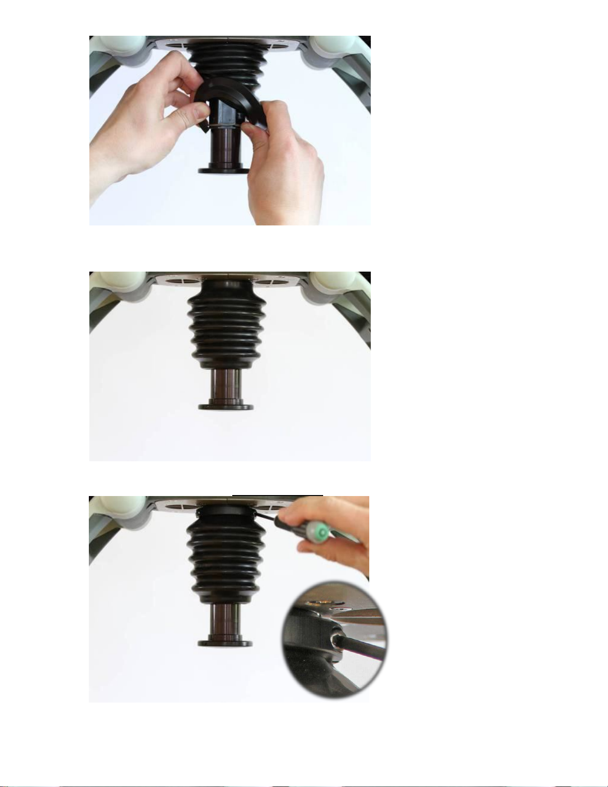
• Remove the Bellows by treading it over the Piston.
2. Reassembling
• Carefully thread the Bellows over the piston and position it as far up as possib le.
• Place the clamp and fixate the bellows by tightening the two screws to 9.0 in-lbs / 1.0 NM with a Torque
Screwdriver Torx 10 (T10) / or 13.0 in-lbs / 1.5 NM with a Torx 20 (T20) depending on Bellows Clamp.
The clamp should be positioned as far up as possible.
LUCAS® 3 Chest Compression System – Service Manual
3328798-002, ©2017 Physio-Control, Inc.
Page 61 of 91
Page 62

• Place the Bellows ring above the retaining ring.
1. Protective Linear sensor Cable (on the
• Thread the edge of the Bellows over the Bellows ring.
• Put back the Suction Cup.
3. Test
Perform a Function Check according to Function Check
How to Replace the Compression Module
1. Disassembling
• Take off the Suction Cup and remove the Bellows according to Disassembling instruction in
Replace the Bellows.
• Remove the Hood according to instructions in How to Replace the Hood.
• Disconnect the following cables according to pictures below
.
How to
back side of Protective PCB)
2. Communication Cable
3. Motor Rotation Sensor Cable
4. Control Linear sensor Cable
5. Speaker Cable
6. Fan Cable
7. Antenna Cable
LUCAS® 3 Chest Compression System – Service Manual
3328798-002, ©2017 Physio-Control, Inc.
Page 62 of 91
Page 63

8. Protective Power Cable
10. Motor Power Cable; use
Remove if taking out Compression
Remove if taking out Protective
9. Control Power Cable
Module
PCB
a small flat screwdriver
to remove the cables,
three wires:
Black (top)
Red (middle)
Yellow (bottom)
• From beneath, remove the four screws that hold the Compression Module with a Torx 25 (T25)
Screwdriver.
• Remove the two screws that hold the Fan Bracket with a Torx 25 (T25) Screwdriver, and remove the
bracket.
LUCAS® 3 Chest Compression System – Service Manual
3328798-002, ©2017 Physio-Control, Inc.
Page 63 of 91
Page 64

• Loosen the two remaining screws on the other bracket without removing them.
• Remove the four screws that hold the PCB brackets against the Compression Module, two screws on each
side according to the pictures below with a Torx 10 (T10) Screwdriver
LUCAS® 3 Chest Compression System – Service Manual
3328798-002, ©2017 Physio-Control, Inc.
Page 64 of 91
Page 65

•
Carefully spread the PCB boards and lift out the Copression Module, make sure that no cables get stuck or
harmed especially the Linear sensor Cables.
2. Reassembling
• Carefully lower the Compression Module down between the PCB’s.
• Position the PCB boards and fasten the Compression Module in the PCB brackets, use thread lock fluid
and tighten to 9.0 in-lbs / 1.0 Nm with a Torque Screwdriver Torx 10 (T10).
• Put back the Fan Bracket, use thread lock fluid and tighten to 35 in-lbs / 4.0 Nm with a Torque
Screwdriver Torx 25 (T25).
• Fasten the Compression Module with four screws, use thread lock fluid and tighten to 35 in- lbs / 4.0 Nm
with a Torque Screwdriver Torx 25 (T25).
• Unscrew the two screws on the bracket that are loose, apply thread lock fluid and tighten to 35 in-lbs / 4.0
Nm with a Torque Screwdriver Torx 25 (T25).
• Re-connect all cables according to picture in Disassembling.
• Replace removed Cable Ties (if applicable).
• Put back the Hood according to Reassembling instruction in How to Replace the Hood
• Put back the Bellows according to Reassembling instruction in How to Replace the Bellows.
• Put back the Suction Cup.
3. Test
LUCAS® 3 Chest Compression System – Service Manual
3328798-002, ©2017 Physio-Control, Inc.
Page 65 of 91
.
Page 66

Perform a Function Check according to Function Check
Antenna Cable
Communication
How to Replace the Drive Belt
1. Disassembling
• Remove the Hood according to Disassembling instruction in How to Replace the Hood
• Disconnect the Antenna Cable Connector and the Communication Cable from the Communication Board
as shown in picture below
.
Cable
Connector
• Remove the Belt Cover by removing the four screws with a Torx 10 (T10) Screwdriver; be careful not to
lose the washers.
• Cut the Belt with cutting plier and remove it.
2. Reassembling
• Thread the new Belt over the small Belt Wheel first.
• Continue to Thread it over the Large Belt Wheel and turn the wheel at the same time to get the belt in
place.
LUCAS® 3 Chest Compression System – Service Manual
3328798-002, ©2017 Physio-Control, Inc.
Page 66 of 91
Page 67

• Fasten the Belt Cover according to the picture in Disassembling. Tighten the screws to 9 in-lbs / 1.0 Nm
with a Torque Screwdriver Torx 10 (T10). Note: Do not use any Thread Lock Fluid!
• Connect the Antenna Cable Connector to the Communication Board and tuck away the antenna cable
beneath antenna and between belt cover and Control PCBA.
• Connect the Communication Cable.
• Put back the Hood according to Reassembling instruction in How to Replace the Hood
3. Test
Perform a Function Check according to Function Check
How to Replace the Electric Motor
1. Disassembling
• Follow Disassembling instructions in How to Replace the Compression Module
Compression Module.
• Remove the Drive Belt according to Disassembling instr uc tion in How to Replace the Drive Belt.
• Take note of how the terminal for Hood Ground Cable is angled.
• Remove the inner two screws and loosen the outer two screws holding the Motor with a Torx 20 (T20)
Screwdriver.
.
.
to take out the
• Slide the Motor out from its bracket.
LUCAS® 3 Chest Compression System – Service Manual
3328798-002, ©2017 Physio-Control, Inc.
Page 67 of 91
Page 68

2. Reassembling
• Apply Thread Lock Fluid on two of the screws and place them in the bracket according to picture below
• Apply Thread Lock Fluid to the other two screws and put them on the Motor together with the lock washer
and terminal. Make sure that the cable outlet is oriented as figure below.
• Slide the Motor onto the Bracket and tighten the screws to 18.8 in-lbs / 2.0 Nm with a Torque Screwdriver
Torx 20 (T20), and make sure to angle the terminal so the ferrite of the Hood Power Cable is secured
behind the Hood Ground Cable connector.
LUCAS® 3 Chest Compression System – Service Manual
3328798-002, ©2017 Physio-Control, Inc.
Page 68 of 91
Page 69

• Put back the Drive Belt according to Reassembling in s truc tion in How to Replace the Drive Belt.
Terminal
Motor Cable Outlet
• Put back the Compression Module according to Reassembling instruction in How to Replace the
Compression Module.
• Put back the Hood according to Reassembling instruction in How to Replace the Hood.
• Put back the Bellows according to Reassembling instruction in How to Replace the Bellows.
• Put back the Suction Cup.
3. Test
Perform a Function Check according to Function Check
How t o Repl ac e the Control PCBA
1. Disassembling
• Before disassembling and changing any PCB and if possible; connect a laptop and perform “Store View”
using LUCAS® 3 Program Loader
• Follow Disassembling instructions in How to Replace the Compression Module to take out the
Compression Module.
• Remove the two remaining screws from beneath and lift out the PCB carefully.
• Warning: Always use ESD protection when handling PCBs!
• Remove SD-card from old Controller PCB. Check that the SD-card is intact and readable/writeable. If SD-
card is working properly keep it for the new Controller PCB.
• Remove Communication PCB according to the Disassembling Instruction in
Communication PCB
.
.
How to Replace the
LUCAS® 3 Chest Compression System – Service Manual
3328798-002, ©2017 Physio-Control, Inc.
Page 69 of 91
Page 70

2. Reassembling
• Put back the Communication PCBA according to Reassembling instruction in
Communication PCB
• If the SD-card from the old PCBA is working pro perly insert the old SD-card into the new PCBA, otherwise
keep new SD-card installed.
• Put the new Controller PCBA in place and fasten loosely with two screws together with the Bottom Plate
with a Torx 25 (T25) Screwdriver.
• Put back the Compression Module ac cor din g to Reassembling instruction in
Compression Module
• Put back the Hood according to Reassembling instruction in How to Replace the Hood.
• Put back the Bellows according to Reassembling instruction in How to Replace the Bellows.
• Put back the Suction Cup.
3. Programming
• Connect a laptop and program the Controller PCBA according to LUCAS® 3 Program Loader
• Check that “Device S/N”, Time and Date, “Total Number of Strokes”, “Hardware ID” and “Device Friendly
Name” are correct (if possible check against “Store View” performed in Disassembling step). If “Store View”
was not possible set: “Device S/N” (e.g. 35160021) and “Hardware ID” (e.g. 100921-00) according to Type
Label, “Total Number of Strokes” to 0 (zero) and “Device Friendly Name” to “LUCAS3-“ + serial number
according to Type Label.
4. Test
Perform a Function Check according to Function Check
How to Replace the
How to Replace the
.
.
How to Replace the Protective PCBA
1. Disassembling
• Before disassembling and chang ing any PCBA and if possible; connect a laptop and perform “Store View”
using LUCAS® 3 Program Loader
• Follow Disassembling instructions in How to Replace the Controller PCB to take out the Protective PCBA.
• Warning: Always use ESD protection when handling PCBAs.
2. Reassembling
• Put the new PCBA in place and fasten loosely with two screws together with the Bottom Plate with a Torx
25 (T25) Screwdriver.
• Put back the Compression Module according to Reassembling instruction in
Compression Module
LUCAS® 3 Chest Compression System – Service Manual
3328798-002, ©2017 Physio-Control, Inc.
Page 70 of 91
.
How to Replace the
Page 71

• Put back the Hood according to Reassembling instruction in How to Replace the Hood
Fan Cable
• Put back the Bellows according to Reassembling instruction in How to Replace the Bellows.
• Put back the Suction Cup.
3. Programming
• Connect a laptop and program the Protective PCB according to LUCAS® 3 Program Loader
• Check that “Device S/N”, Time and Date, “Total Number of Strokes”, “Hardware ID” and “Device Friendly
Name” are correct (if possible check against “Store View” performed in Disassembling step). If “Store View”
was not possible set: “Device S/N” (e.g. 35160021) and “Hardware ID” (e.g. 100921-00) according to Type
Label, “Total Number of Strokes” to 0 (zero) and “Device Friendly Name” to “LUCAS3-“ + serial number
according to Type Label.
4. Test
Perform a Function Check according to Function Check
How to Replace the Electric Fan
1. Disassembling
• Lift of the hood by following Disassembling instructions in How to Replace the Hood
to disconnect the cables.
• Disconnect the Fan Cable on the Control PCB
.
.
.
, it’s not necessary
• Remove the four screws that hold the Fan (under the battery side, two more screws are hidden under the
robber bellows) wit h a Flat 5.5x0.8 mm (5.5) Screwdriver.
• Take off the Threaded pla te and lift out the Fan.
2. Reassembling
LUCAS® 3 Chest Compression System – Service Manual
3328798-002, ©2017 Physio-Control, Inc.
Page 71 of 91
Page 72

• Make sure all parts are assembled as picture below. The screws shall be locked with thread lock fluid and
Fan Cable connection
Threaded plate
tightened to 9 in-lbs / 1.0 Nm with a Torque Screwdriver Flat 5.5x0.8 mm (5.5).
Cable outlet
Fan
Fan washer
Mesh
Bracket
Screw X4
• Connect the Fan Cable to the “Optional” connector on the Control PCB. Place the cable between the coils
according to the picture below.
• Put back the Hood according to Reassembling instruction in How to Replace the Hood.
3. Test
• Perform a Function Check according to Function Check
LUCAS® 3 Chest Compression System – Service Manual
3328798-002, ©2017 Physio-Control, Inc.
• When the device is in active mode let it run, after approximately 10 minutes the fan should start. Now set
the device in adjust mode, the fan should continue running. Check that there is no unusual sound from the
fan. When the temperature inside the hood has decreased to 30°C (86°F) the fan should stop. Continue
with the Function Check.
.
Page 72 of 91
Page 73

Turning the Snap
Take out Patient
How to Replace the Support Leg
This procedure can be used for replacing the Support Leg or replacing the Axel-Angle Shaft.
1. Disassembling
• Remove the Patient Strap.
• Remove the Bumper.
• Remove Snap Ring by turning the open end of ring to the open edges of the leg, shown in the pictur e; and
take it out (two rings, one on each side).
• Remove the Patient Strap Holders (two, one on each side).
Ring to the open
area and take it
out
• Lay LUCAS on the side of table with nothing blocking the shaft underneath. The round end of spring
should be facing up according to the pictures below.
LUCAS® 3 Chest Compression System – Service Manual
3328798-002, ©2017 Physio-Control, Inc.
Strap Holders
Page 73 of 91
Page 74

Knock the Spring from
round end out of shafts.
Spring with a round end facing up (non-
Spring with a flat end facing down (press
Spring
press fitted side)
• Knock the Spring o ut with a Hammer and a Mandrel or similar tool. Tap the spring downwards with the
mandrel and hammer until it falls loose.
fitted side)
• When the Spring is removed from the Angle Shaft, turn the device over so the press fitted side is facing up.
Using the metal Pin or similar tool and Hammer, push the bottom, non press-fitted Ang el Sh af t out of
Support Leg. Always knock out the non pres s f itted Angle Shaft first.
LUCAS® 3 Chest Compression System – Service Manual
3328798-002, ©2017 Physio-Control, Inc.
Page 74 of 91
Page 75
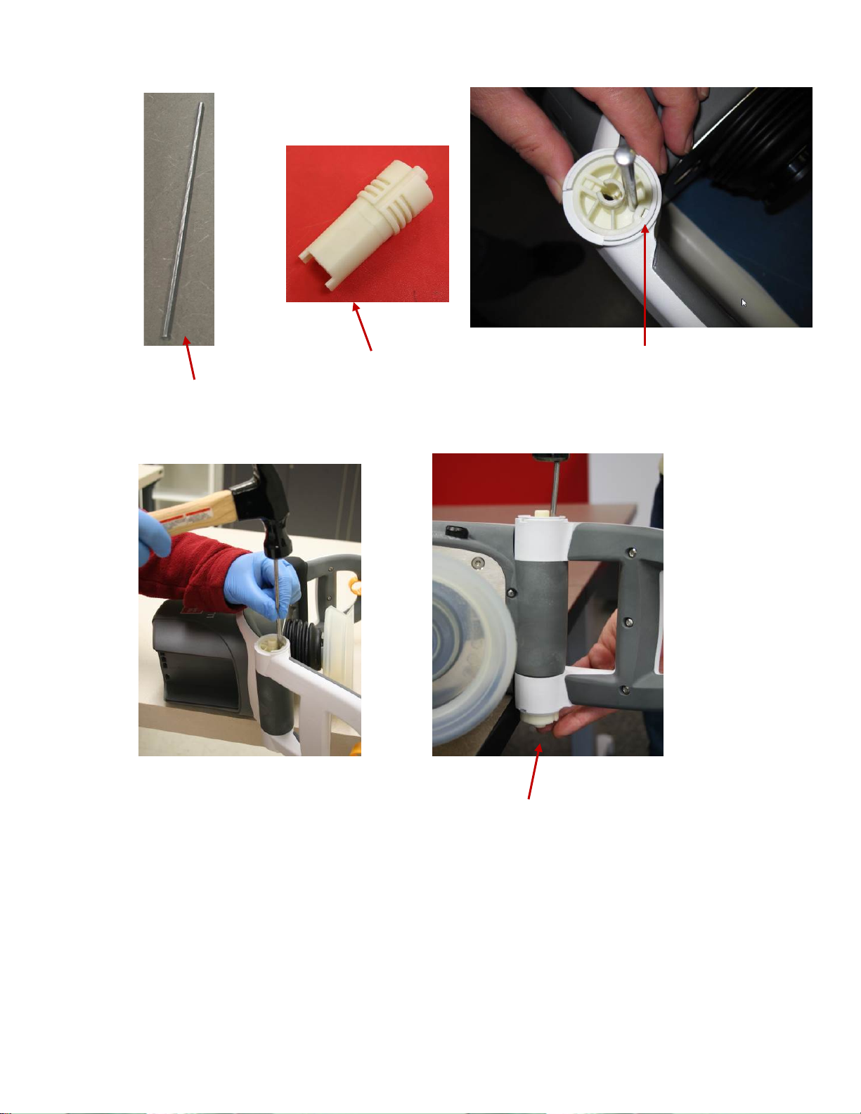
The bottom, non-press fitted
Angel Shaft
Metal Pin
Press Fitted Side with Key
Angel Shaft
• Turn the leg on the other side; and use the Angel Shaft Tool (optional tool) or similar tool with a Hammer
to knock out the press fitted Angle Shaft, which is fitted into the Main Body.
LUCAS® 3 Chest Compression System – Service Manual
3328798-002, ©2017 Physio-Control, Inc.
Page 75 of 91
Page 76

On the same level
Angle Shaft Tool
Use this end to remove
Use this end to install
During this
- Mandrel, LUCAS Hinge Insertion (Optional Tool) -
• Remove the Support Leg.
2. Reassembling
• With LUCAS still on the side, place the new support leg fully extended out from LUCAS.
• Insert the Angle Shafts; start with the one that is press fitted into the Main Body, oriented as picture
below. Knock it down so that it is completely flush into the Support Leg.
reassembling step, the
keyways for the Spring
should always be
pointing towards the
Compression Module on
both shafts.
Note: Notch of the Angle
Shaft pointing toward
the claws.
LUCAS® 3 Chest Compression System – Service Manual
3328798-002, ©2017 Physio-Control, Inc.
Page 76 of 91
Page 77

• Turn LUCAS over on the other side and insert the non-press fitted Angle Shaft by hand force until it stops.
Ensure that the keyways for the spring are aligned with each other.
• Insert the Spring with the rounded end first, all the way down through both Angle Shafts. Use a Mandrel
to fully seat the spring into the Angle Shaft.
• Turn the leg inwards to its correct position.
• Ensure the L shaped end of the spring is
properly seated inside the Angle Shaft.
LUCAS® 3 Chest Compression System – Service Manual
3328798-002, ©2017 Physio-Control, Inc.
Page 77 of 91
Page 78

Angel Shaft and
• Carefully hammer down the Angle Shaft with a hammer and the Angle Shaft Tool (Optional Tool) or
similar tool. The surface of the Angle Shaft should be on the same level as the Support Leg. Double
check the L-shaped side of the spring to make sure it is still seated in the Angle Shaft. A mandrel can be
used to tap it into place if not fully seated.
Leg on the same
level
• Put the Patient Strap Holder in place (two sides).
• Install Snap Ring according to the picture below (two sides), place the open end of the ring downwards.
• Slide the Bumper up over the support leg (note the direction of the bumper, skirt edge should be on the
bottom).
• Thread the Bumper over the shaft and the patient strap holder on both sides.
LUCAS® 3 Chest Compression System – Service Manual
3328798-002, ©2017 Physio-Control, Inc.
Page 78 of 91
Page 79

Slide the Bumper up over
Skirt edge on the bottom
Type Label
Type Label and SN
• Mount back the Patient Strap.
the patient strap holders.
• If the replaced Support Leg has a Type Label with SN, and if possible, try to move the existing label on to
the new Support Leg. If that doesn’t work, contact Physio Control to get a new label with the same SN
and Notified Body number.
The Notified Body number “0434” as shown in picture above may be “2460”.
3. Test
Do the following tests to verify that the repair/replacement has been performed correctly:
• Check the locking function by locking and unlocking against the Back Plate.
LUCAS® 3 Chest Compression System – Service Manual
3328798-002, ©2017 Physio-Control, Inc.
Page 79 of 91
Page 80

• Check the function of the torsion spring by folding and unfolding the Support Legs.
Cable Ties
Antenna Cable
• Perform a Function Check according to Function Check
How to Replace the Antenna
1. Disassembling
• Remove the Hood according to instructions in How to Replace the Hood
• Cut out two cable ties
.
Connector
• Disconnect the antenna cable connector from Communicat ion Bo ard
• Remove the antenna board from the belt cover
2. Reassembling
• Pre-bend two cable ties at the bend line marked in red as shown in the picture
• Bend the tip of the cable tie to make it easier go through the hole
• Use a third cable tie (marked with blue arrow in the picture) to guide the cable tie through the holes
LUCAS® 3 Chest Compression System – Service Manual
3328798-002, ©2017 Physio-Control, Inc.
Page 80 of 91
Page 81

Transfer Tapes
• Apply transfer tapes (approximate 7x8mm, 2x) to the belt cover, and remove the tapes protective top layer.
• Place the antenna on top of the transfer tapes and against the surfaces marked with red arrows and in
between flanges marked with green arrows.
• Close and tighten the cable ties by hand until the antenna is secured as shown in the pictures below, with
the cable tie closing position against the edge of the antenna board.
LUCAS® 3 Chest Compression System – Service Manual
3328798-002, ©2017 Physio-Control, Inc.
Page 81 of 91
Page 82

Antenna Cable
• Cut off the excess cable tie tails
• Connect antenna to the Communication Board and tuck away the antenna cable beneath antenna and
between belt cover and Control PCBA.
Connector
• Put back the Hood according to Reassembling instruction in How to Replace the Hood
3. Test
• Perform a Function Check according to Function Check
How to Replace the Communication PCB
1. Disassembling
• Before disassembling and chang ing any PCB and if possible; connect a laptop and perform “Store View”
using LUCAS® 3 Program Loader
• Follow Disassembling instructions in How to Replace the Controller PCB to take out the Controller PCB.
• Use a plier carefully cut off 3 plastic screws that hold the communication PCB on Controller PCB
• Save the plastic spacers and the nuts for reuse
.
.
LUCAS® 3 Chest Compression System – Service Manual
3328798-002, ©2017 Physio-Control, Inc.
Page 82 of 91
Page 83

3 Plastic Screws
1
2
3
• Remove the Communication PCB
2. Reassembling
• Put the new Communication PCB in place with the new plastic screws, plastic spacers, and the nuts
• Finger tightens screws by holding screw head lightly with fingertip until all items are tight against each
other and no play is visible. Do not overtighten.
• Then use tools to tighten screw and nut ¾ of turn (270), tightening order according to the numbers shown
in the picture
• Flatten screws (3x) using a non-knurled flat nose plier right up against the nut shown in the picture below
• Put back the Controller PCB according to Reassembling instruction in
PCB
3. Programming
• Connect a laptop and program the Protective PCB according to LUCAS® 3 Program Loader
• Check that “Device S/N”, Time and Date, “Total Number of Strokes”, “Hardware ID” and “Device Friendly
Name” are correct (if possible check against “Store View” performed in Disassembling step). If “Store View”
was not possible set: “Device S/N” (e.g. 35160021) and “Hardware ID” (e.g. 100921-00) according to Type
Label, “Total Number of Strokes” to 0 (zero) and “Device Friendly Name” to “LUCAS3-“ + serial number
according to Type Label.
4. Test
• Perform a Function Check according to Function Check
.
How to Replace the Controller
.
LUCAS® 3 Chest Compression System – Service Manual
3328798-002, ©2017 Physio-Control, Inc.
Page 83 of 91
Page 84

Replacing the Pow er Inlet
1. Disassembling
• Follow the instructions in Section Replace the Compression Module.
• Follow the instructions in Section Replace the Controller PCB
• Follow the instructions in Section Replace the Protective PCB
Warning: Always use ESD protection when handling PCB’s!
• Remove the four Torx 20 screws to remove the Main Body Lid.
• Use the extraction tool to remove the wires from the Power Inlet.
• With the wires removed you can now remove the nut and Power Inlet.
LUCAS® 3 Chest Compression System – Service Manual
3328798-002, ©2017 Physio-Control, Inc.
Page 84 of 91
Page 85

2. Reassembling
• Install the Power Inlet with the white arrow on top.
• Install the Power Inlet nut and tighten to 9 in-lbs / 1.0 Nm.
• Insert the Power Inlet wires with the red on top.
• Install the Main Body Lid and tighten all four Torx 20 screws to 13 in-lbs / 1.5 Nm
• Re-install the Compression Module, Controller PCB, Pro tective PC B, a nd Hood.
3. Test
• Perform a Function Check according to Section Function Check.
LUCAS® 3 Chest Compression System – Service Manual
3328798-002, ©2017 Physio-Control, Inc.
Page 85 of 91
Page 86

Replacing the Main Body/Fram e Assembly
4. Disassembling
• Follow the instructions in Section Replace the Compression Module.
• Follow the instructions in Section Replace the Controller PCB
• Follow the instructions in Section Replace the Protective PCB
• Follow the instructions in Section Replacing the Power Inlet.
• If replacing the Main Body follow the instructions in Section Replace the Support Legs.
Warning: Always use ESD protection when handling PCB’s!
5. Reassembling
• Re-install the Power Inlet using instructions in section Replacing the Power Inlet.
• Install the Main Body Lid and tighten all four Torx 20 screws to 13 in-lbs / 1.5 Nm.
• Re-install the Compression Module, Controller PCB, Protective PCB, and Hood.
• If removed, re-install the Support Legs.
6. Test
• Perform a Function Check according to Section Function Check.
LUCAS® 3 Chest Compression System – Service Manual
3328798-002, ©2017 Physio-Control, Inc.
Page 86 of 91
Page 87

Function Check
Introduction
LUCAS® 3 is an advanced system consisting of both mechanics and electronics. After each repair or maintenance a
Function Check should be performed to establish all vital functions of the device.
Mechanics Test
With the device turned off perform the following tests:
7. Piston Check
• Pull the Suction Cup down and up to check that the Decompression Spring moves smoothly and without
any unusual noise.
• Pull the Suction Cup down and continue to slo wl y pull do wn until the Carry Ball Nut has reached its lower
position, check that it runs smoothly and without unusual noise.
• Attention: If you push to fast you will feel resistance in steps because the Electrical Motor is affected,
instead push slowly in one long stroke.
• Push the Suction Cup back up to its top position, check that it runs smoothly and without unusual noise.
8. Claw Lock Mechanism Check
• Check for play between the Release Ring and the Support Legs:
• Pull the Release Ring gently to unlock the mechanism and open the Claws.
• Move your finger around in the Release Ring; verify that you can detect some play between the Ring and
the Support Leg. You should be able to hear a rattle from the play in the Ring when moving the Release
Ring from side to side. If the Support Ring is tight against the Support Leg with no play, then the check has
failed.
• Check for the ability of the Claw Mechanism to remain locked:
• Press the Claw Lock towards the center point of the Support leg (closed position) with your thumbs.
• When locked, press hard with two thumbs on the two claws as shown in the picture below. If the claw
mechanism unlocks, then the check has failed.
LUCAS® 3 Chest Compression System – Service Manual
3328798-002, ©2017 Physio-Control, Inc.
Page 87 of 91
Page 88

Electronics Test
Turn on the device and perform the following tests:
1. Check that the Internal Function Test is performed and that the ADJUST LED shows a green light.
2. Change mode to ACTIVE (30:2) and check that the ACTIVE (30:2) LED shows a green light. Let the device run
for approximately two minutes and listen for unusual noise. Check that there is an audible alert sound prior to the
ventilation pause (each 30 strokes at default settings) together with an intermittent LED.
3. Change mode to PAUSE and check that the PAUSE LED shows a green light.
4. Change mode to ACTIVE (continuous) and check that the ACTIVE (continuous) LED shows a green light. The
LED will then blink each ten strokes (ventilation alert).
5. Change mode to ADJUST, pull the Suction Cup down to test the Adjustment Servo. Push the Suction Cup back
up to its top position. Check that it runs smoothly.
6. Connect a charger to the device and check that the charging sequence begins (the battery LED’s show a
“running” light). Disconnect the charger.
7. Turn the device off.
8. Testing Transmit mode by following Connect the device via Bluetooth
Program Loader.
• If the device has undergone Maintenance and has passed the Function Check press “Set PC Date” to change
“Last Service Date”.
• If the device has undergone a Repair without Maintenance, do NOT press “Set PC Date” (a connection
between the device and laptop still has to be established to check that the communication is working).
®
• Press OFF in LUCAS
3 Program Loader to switch off the Bluetooth communication. Check the Bluetooth
light is off.
to make connect to a PC using LUCAS® 3
LUCAS® 3 Chest Compression System – Service Manual
3328798-002, ©2017 Physio-Control, Inc.
Page 88 of 91
Page 89

Accessories
LUCAS Battery Charger
The battery charger is sold as an accessory.
For more information about different country specific variants see the list of Accessories
the battery charger, if broken replace with a new.
. There are no serviceable parts in
LUCAS Car Cable
The car cable is sold as an accessory with the product cat #: 11576-000048.
LUCAS® 3 Chest Compression System – Service Manual
3328798-002, ©2017 Physio-Control, Inc.
Page 89 of 91
Page 90

LUCAS Power Supply
The power supply is sold as an accessory.
For more information about different country specific variants see the list of Accessories
parts in the power supply, if broken replace with a new.
. There are no serviceable
LUCAS® 3 Chest Compression System – Service Manual
3328798-002, ©2017 Physio-Control, Inc.
Page 90 of 91
Page 91

Appendix A (wiring diagram)
LUCAS® 3 Chest Compression System – Service Manual
3328798-002, ©2017 Physio-Control, Inc.
Page 91 of 91
 Loading...