

Page 1
Medical
For parts or technical
assistance call
800 327 0770 (option 2)
Birthing Bed
Model LD304
Operations
Manual
Important
Information
File in your
maintenance
records
Page 2

Table of Contents
Introduction
Specifications 2. . . . . . . . . . . . . . . . . . . . . . . . . . . . . . . . . . . . . . . . . . . . . . . . . . . . . . . . . . . . . . . . . . . . . . . . . .
Warning / Caution / Note Definition 3. . . . . . . . . . . . . . . . . . . . . . . . . . . . . . . . . . . . . . . . . . . . . . . . . . . . . . . .
Safety Tips And Guidelines 4, 5. . . . . . . . . . . . . . . . . . . . . . . . . . . . . . . . . . . . . . . . . . . . . . . . . . . . . . . . . . . . . . . .
Bed Symbols 6. . . . . . . . . . . . . . . . . . . . . . . . . . . . . . . . . . . . . . . . . . . . . . . . . . . . . . . . . . . . . . . . . . . . . . . . . . . . . .
Unpacking Instructions and Set−Up Procedures 7. . . . . . . . . . . . . . . . . . . . . . . . . . . . . . . . . . . . . . . . . . . . . . . .
Bed Illustration 8. . . . . . . . . . . . . . . . . . . . . . . . . . . . . . . . . . . . . . . . . . . . . . . . . . . . . . . . . . . . . . . . . . . . . . . . . . . . .
Siderail Operation Guide
Operating Siderails 9. . . . . . . . . . . . . . . . . . . . . . . . . . . . . . . . . . . . . . . . . . . . . . . . . . . . . . . . . . . . . . . . . . . . . .
Using the Siderail Control Panel Lights 9. . . . . . . . . . . . . . . . . . . . . . . . . . . . . . . . . . . . . . . . . . . . . . . . . . . .
Locking Out the Siderail Controls 9. . . . . . . . . . . . . . . . . . . . . . . . . . . . . . . . . . . . . . . . . . . . . . . . . . . . . . . . .
Outside Siderail Controls 10, 11. . . . . . . . . . . . . . . . . . . . . . . . . . . . . . . . . . . . . . . . . . . . . . . . . . . . . . . . . . . .
Inside Siderail Controls 12, 13. . . . . . . . . . . . . . . . . . . . . . . . . . . . . . . . . . . . . . . . . . . . . . . . . . . . . . . . . . . . . .
Pendant Operation Guide 14−16. . . . . . . . . . . . . . . . . . . . . . . . . . . . . . . . . . . . . . . . . . . . . . . . . . . . . . . . . . . . . . .
Bed Operation
Using the Brake/Steer Pedals 17. . . . . . . . . . . . . . . . . . . . . . . . . . . . . . . . . . . . . . . . . . . . . . . . . . . . . . . . . . .
Using the Manual Motor Crank 17. . . . . . . . . . . . . . . . . . . . . . . . . . . . . . . . . . . . . . . . . . . . . . . . . . . . . . . . . .
Activating Instant CPR 17. . . . . . . . . . . . . . . . . . . . . . . . . . . . . . . . . . . . . . . . . . . . . . . . . . . . . . . . . . . . . . . . .
Removing the Head Board 18. . . . . . . . . . . . . . . . . . . . . . . . . . . . . . . . . . . . . . . . . . . . . . . . . . . . . . . . . . . . . .
Night Light 18. . . . . . . . . . . . . . . . . . . . . . . . . . . . . . . . . . . . . . . . . . . . . . . . . . . . . . . . . . . . . . . . . . . . . . . . . . . .
Nurse Call Battery 18. . . . . . . . . . . . . . . . . . . . . . . . . . . . . . . . . . . . . . . . . . . . . . . . . . . . . . . . . . . . . . . . . . . . .
Using the Labor Grips 19. . . . . . . . . . . . . . . . . . . . . . . . . . . . . . . . . . . . . . . . . . . . . . . . . . . . . . . . . . . . . . . . . .
Using the Labor Bar 19. . . . . . . . . . . . . . . . . . . . . . . . . . . . . . . . . . . . . . . . . . . . . . . . . . . . . . . . . . . . . . . . . . . .
Lumbar and Perineal Wedge 19. . . . . . . . . . . . . . . . . . . . . . . . . . . . . . . . . . . . . . . . . . . . . . . . . . . . . . . . . . . .
Adjustable Seat Depth 19. . . . . . . . . . . . . . . . . . . . . . . . . . . . . . . . . . . . . . . . . . . . . . . . . . . . . . . . . . . . . . . . . .
Removing the Foot Section 20. . . . . . . . . . . . . . . . . . . . . . . . . . . . . . . . . . . . . . . . . . . . . . . . . . . . . . . . . . . . .
Operating the Glideaway Foot Rests 20. . . . . . . . . . . . . . . . . . . . . . . . . . . . . . . . . . . . . . . . . . . . . . . . . . . . .
Birthing Bed Positioning 21. . . . . . . . . . . . . . . . . . . . . . . . . . . . . . . . . . . . . . . . . . . . . . . . . . . . . . . . . . . . . . . .
Delivery Table Positioning 21. . . . . . . . . . . . . . . . . . . . . . . . . . . . . . . . . . . . . . . . . . . . . . . . . . . . . . . . . . . . . . .
Trendelenburg Positioning 21. . . . . . . . . . . . . . . . . . . . . . . . . . . . . . . . . . . . . . . . . . . . . . . . . . . . . . . . . . . . . .
Pelvic Tilt 21. . . . . . . . . . . . . . . . . . . . . . . . . . . . . . . . . . . . . . . . . . . . . . . . . . . . . . . . . . . . . . . . . . . . . . . . . . . . .
Using the Permanently Attached IV Pole
22. . . . . . . . . . . . . . . . . . . . . . . . . . . . . . . . . . . . . . . . . . . . . . . . .
Cleaning 23. . . . . . . . . . . . . . . . . . . . . . . . . . . . . . . . . . . . . . . . . . . . . . . . . . . . . . . . . . . . . . . . . . . . . . . . . . . . . . . . .
Preventative Maintenance Checklist 24. . . . . . . . . . . . . . . . . . . . . . . . . . . . . . . . . . . . . . . . . . . . . . . . . . . . . . . . .
Limited Warranty
Obtaining Parts and Service 25. . . . . . . . . . . . . . . . . . . . . . . . . . . . . . . . . . . . . . . . . . . . . . . . . . . . . . . . . . . . .
Supplemental Warranty Coverage 25. . . . . . . . . . . . . . . . . . . . . . . . . . . . . . . . . . . . . . . . . . . . . . . . . . . . . . . .
Return Authorization 26. . . . . . . . . . . . . . . . . . . . . . . . . . . . . . . . . . . . . . . . . . . . . . . . . . . . . . . . . . . . . . . . . . .
Freight Damage Claims 26. . . . . . . . . . . . . . . . . . . . . . . . . . . . . . . . . . . . . . . . . . . . . . . . . . . . . . . . . . . . . . . . .
Page 3

Introduction
INTRODUCTION
This manual is designed to assist you with the operation of the LD304 Birthing Bed. Read it thoroughly before
using the equipment or beginning any maintenance on it.
PRODUCT DESCRIPTION
This product is an electrically operated maternity bed designed for general patient care use. Major functions
include: raising and lowering of the litter , raising and lowering of the head and foot end portions and Trendelenburg−like function.
SPECIFICATIONS
Safe Working Load 500 pounds (227 kilograms)
Weight of Product 475 pounds (215 kilograms) ; standard configuration
525 pounds (238 kilograms) ; all options/accessories
Bed Length/Width 93” x 41” (with siderails up) − 37” (with siderails down)
236 cm x 104 cm (with siderails up) − 94 cm (with siderails down)
Bed Height (to top of seat) Low − 17.5” (44 cm), High − 35.5” (90 cm) (w/6” Casters)
Mattress Size Head − 49.5” (126 cm) x 33” (84 cm) x 5” (13 cm), Foot − 30” (76 cm) x
30” (76 cm) x 3” (8 cm), Patient Sleep Surface − 81” (206 cm)
Caster Size 6” Standard; 8” Optional
Critical Angles Maximum Elevation − Head 70, Trendelenburg 8
Foot Section Height Foot Section Travel − 0” (0 cm) Up / 7” (17.8 cm) Down
Break−Away Point from Wall 60” (152 cm)
Electrical Standard 4 motor function: Head−Bed−Foot−Trendelenburg
120 VAC, 60 Hz, 10 Amp
Optional: 230 VACY, 50/60 Hz, 10Amp
Current leakage less than 300 microamperes (per UL 60601−1).
Hospital grade plug and 3−wire heavy duty cord.
Compatible with non−flammable anesthetic agents and oxygen by nasal
catheter or mask type.
Rated Duty Cycle 5% / hr (Continuous Operation with Short−Time Loading)
Environmental Conditions Operation Storage and Transportation
Temperature
Relative Humidity
Atmospheric Pressure
Stryker reserves the right to change specifications without notice.
Specifications listed are approximate and may vary slightly from unit to unit or by power supply fluctuations
2
Page 4

Introduction
WARNING / CAUTION / DANGER / NOTE DEFINITION
The words WARNING, CAUTION and NOTE carry special meanings and should be carefully reviewed.
WARNING or DANGER
Alerts the reader about a situation, which if not avoided, could result in death or serious injury. It may also
describe potential serious adverse reactions and safety hazards.
CAUTION
Alerts the reader of a potentially hazardous situation, which if not avoided, may result in minor or moderate
injury to the user or patient or damage to the equipment or other property. This includes special care necessary for the safe and effective use of the device and the care necessary to avoid damage to a device that
may occur as a result of use or misuse.
NOTE
This provides special information to make maintenance easier or important instructions clearer.
3
Page 5

Introduction
SAFETY TIPS AND GUIDELINES
Before operating the Stryker LD304 Birthing Bed, it is important to read and understand all information in this
manual. Carefully read and strictly follow the safety guidelines listed on this page.
It is important that all users have been trained and educated on the inherent hazards associated with the
usage of electric beds.
To ensure its proper use and the safety of patients and staff, the LD304 Birthing Bed has been marked with
the following caution and warning labels:
DANGER Explosion Hazard − do not use in the presence of flammable anesthetics.
CAUTION This unit is equipped with a hospital grade attachment plug. Grounding reliability can be
achieved only when equipment is connected to equivalent receptacle.
CAUTION Electrical shock hazard. Do not remove cover panels. Refer all servicing to qualified personnel.
CAUTION Disconnect the power cord while using the manual hand crank.
WARNING
Powered bed mechanisms can cause serious injury. Operate bed only when all persons are clear of the
mechanisms.
To help reduce the number and severity of falls by patients, always leave the bed in the lowest position
when the patient is unattended.
When raising the siderails, listen for the ”click” that indicates the siderail has locked in the up position.
Pull firmly on the siderail to ensure it is locked into position. Siderails are not intended to be a patient
restraint device. It is the responsibility of attending medical personnel to determine the degree of restraint
and the siderail positioning necessary to ensure a patient will remain safely in bed. The intermediate position should be used only to assist the patient during ingress and egress from the bed.
Always apply the caster brakes when a patient is getting on or off the bed. Always keep the caster brakes
applied when a patient is on the bed (except during transport). Serious injury could result if the bed moves
while a patient is getting in or out of bed. After the brake pedal is applied, push on the bed to ensure the
brakes are locked. When moving the bed, put the pedal in the steer position. This locks the swivel motion
of the right foot end caster and makes the bed easier to move.
The instant CPR release is for emergency use only. Before activating the instant CPR, verify all persons
and equipment are away from the area below and around the Fowler (back rest) section of the bed or
serious personal injury or damage to the equipment could occur.
Prior to placing weight on the foot section, verify the locking bar has been lowered and locked. The foot
section locking bar is not designed for use as a grasping bar or other patient assist device.
When large spills occur in the area of the circuit boards, 110 volt cables and motors, immediately unplug
the bed power cord from the wall socket. Remove the patient from the bed and clean up the fluid. Have
maintenance completely check the bed. Fluids can have an affect on operational capabilities o f any electrical product. DO NOT put the bed back into service until it is completely dry and has been thoroughly
tested for safe operation.
To avoid entanglement, possibly resulting in frayed power cords and risk of electrical shock, wrap the bed
power cord around the roller bumpers at the head end of the bed during transport.
There is a possible fire hazard when using oxygen administering equipment of other than the nasal, mask,
or 1/2−bed−length tent type. Oxygen tent should not extend below the mattress support platform. Siderails must be kept outside of the oxygen tent.
4
Page 6

Introduction
SAFETY TIPS AND GUIDELINES (CONTINUED)
CAUTION
Do not steam clean or hose off the bed. Do not immerse any part of the bed. The internal electric parts
may be damaged by exposure to water. Hand wash all surfaces of the bed with warm water and mild
detergent. Dry thoroughly. Inspect the mattress cover after each use. Discontinue use if any cracks or
rips are found in the cover which may allow fluids to enter the mattress. Exposure to fluids may cause
injury to patient and/or user.
Preventative maintenance should be performed at a minimum of annually to ensure all bed features are
functioning as designed. Close attention should be given to safety features including, but not limited to:
Safety side latching mechanisms, Caster braking system,
Frayed electrical cords and components, Leakage current 300 microamperes max.
Protective earth ground impedance 100 milliohms max.
No controls or cabling entangled in bed mechanisms,
All electrical controls return to off or neutral position when released,
For additional maintenance information, refer to your maintenance manual.
Always unplug bed during service or cleaning. When working under the bed with the bed in the high posi-
tion, always place blocks under the litter frame and set the brakes to prevent injury in case the Bed Down
switch is accidently pressed.
Hand wash all surfaces of the bed with warm water and mild detergent. Dry thoroughly. DO NOT STEAM
CLEAN, PRESSURE WASH, HOSE OFF OR ULTRASONICALLY CLEAN. Using these methods of
cleaning is not recommended and may void this product’s warranty.
Inspect the mattress cover after each use. Discontinue use if any cracks or rips are found in the cover
which may allow fluids to enter the mattress. Exposure to fluids may cause injury to patient and/or user.
To avoid injury, unplug the bed power cord from the wall socket before using the manual hand crank.
The LD304 Birthing Bed is equipped with a hospital grade plug for protection against electric shock haz-
ard. It must be plugged directly into a properly grounded three−prong receptacle. Grounding reliability
can be achieved only when a hospital grade receptacle is used.
To avoid damage, the weight of the IV bags should not exceed 40 pounds.
To avoid damage while transporting the bed, verify the IV pole is at a low enough height to allow it to pass
safely through door openings.
5
Page 7
Bed Symbols
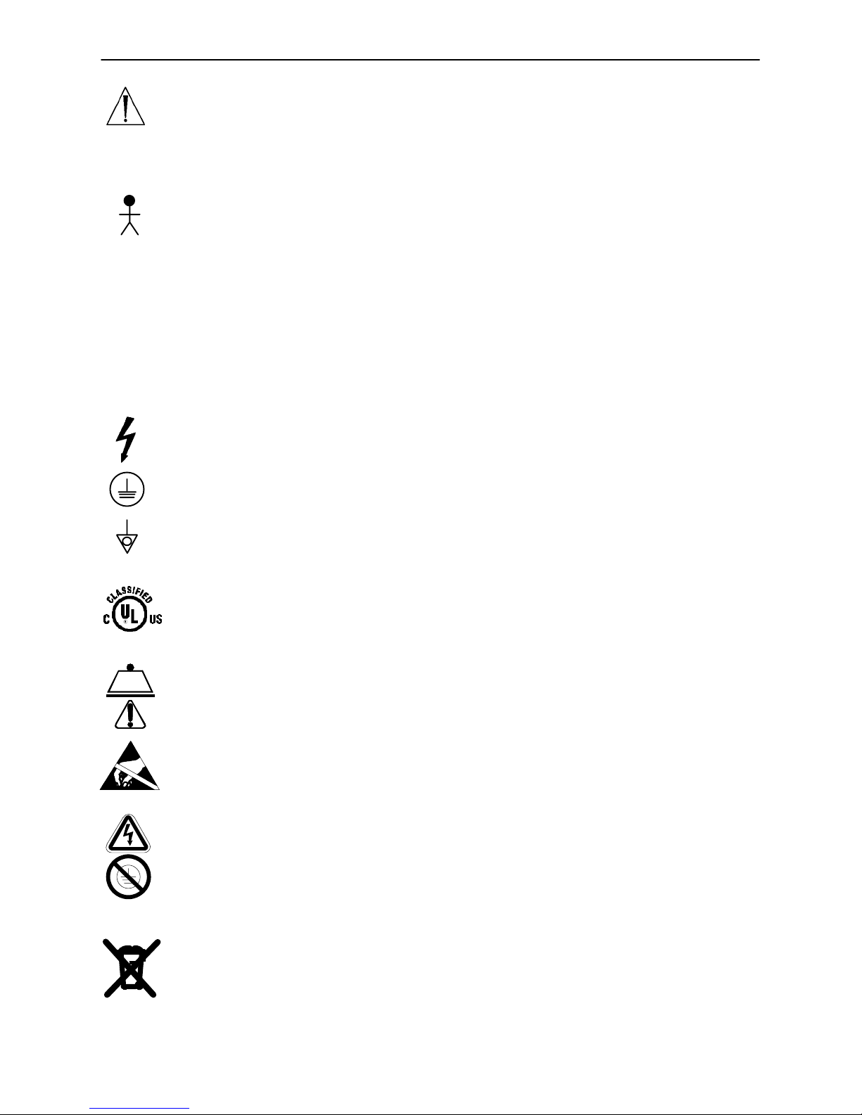
Warning, Refer to Operations or Service/Maintenance Manual
~
Alternating Current
Type B Equipment: equipment providing a particular degree of protection against electric shock, particularly regarding allowable leakage current and reliability of the protective earth connection.
Class 1 Equipment: equipment in which protection against electric shock does not rely
on BASIC INSULA TION only, but which includes an additional safety precaution in that
means are provided for the connection of the EQUIPMENT to the protective earth conductor in the fixed wiring of the installation in such a way that ACCESSIBLE METAL
PARTS cannot become live in the event of a failure of the BASIC INSULATION.
Duty Cycle − 5% / hr (Continuous Operation with Short−Time Loading)
IPX4: Protection from liquid splash
Dangerous Voltage Symbol
Protective Earth Terminal
Potential Equalization Symbol
Medical Equipment Classified by Underwriters Laboratories Inc. with Respect to Electric Shock, Fire, Mechanical and Other Specified Hazards Only in Accordance with UL
60601−1, First Edition (2003) and CAN/CSA C22.2 No. 601.1−M90 with updates 1 and
2
Safe Working Load Symbol
Caution: Electrostatic Sensitive
Warning: Non−Protectively Earthed, Potential for Risk of Electric Shock
In accordance with European Directive 2002/96/EC on Waste Electrical and Electronic
Equipment, this symbol indicates that the product must not be disposed of as unsorted
municipal waste, but should be collected separately. Refer to your local distributor for
return and/or collection systems available in your country.
6
Page 8
Unpacking and Initial Set−Up Procedures
UNPACKING INSTRUCTIONS
Refer to unpacking instructions attached to the bed inside the crate.
SET−UP PROCEDURES
It is important that the LD304 Birthing Bed is working properly before it is put into service. The following list
will help ensure each part of the bed is tested.
Plug the bed power cord into a properly grounded, hospital grade wall receptacle. During transport, the
bed power cord should be wrapped around the roller bumpers at the head end of the bed.
CAUTION
The LD304 Birthing Bed is equipped with a hospital grade plug for protection against electric shock hazard.
It must be plugged directly into a properly grounded three−prong receptacle. Grounding reliability can be
achieved only when a hospital grade receptacle is used.
Ensure the siderails raise and lower smoothly and lock in the up position.
Ensure the brakes hold when the brake pedal is engaged.
Test each function on the (optional) hand pendant and verify each function is working properly.
Beds equipped with nurse communication siderail control option only:
Plug the interface cable into the 37 pin connector in the litter frame at the head end of the bed, and into
the ”Patient Station”, ”Head Wall”, ”Docker Station”, or equivalent (whichever applies).
Run through each function on the siderail control panels and verify each function is working properly.
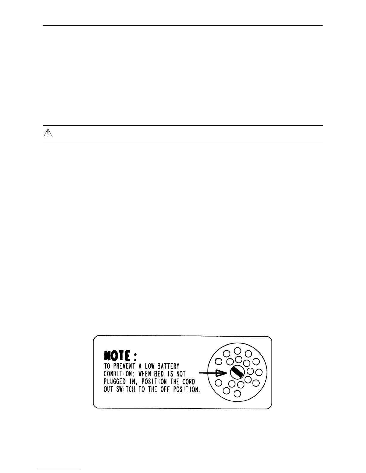
NOTE
To prevent a low battery condition when the bed is not plugged in, position the cord out switch at the head
end of the bed to the off position. The switch is identified by the label shown below. If the switch is not positioned as shown below and the bed power cord and pendant cord are unplugged, the life of the back−up battery will be significantly reduced.
If the POWER LED (located on the outside of both siderails) is flashing, the 9V Nurse Call battery needs to
be replaced. The battery is located at the head end of the bed. No tools are required to replace the battery .
Unplug the bed power cord from the wall socket and replace the battery. After replacing the battery, verify
the POWER LED is no longer flashing and operates normally when the different light settings are selected.
Properly dispose of the old battery in accordance with local regulations.
7
Page 9
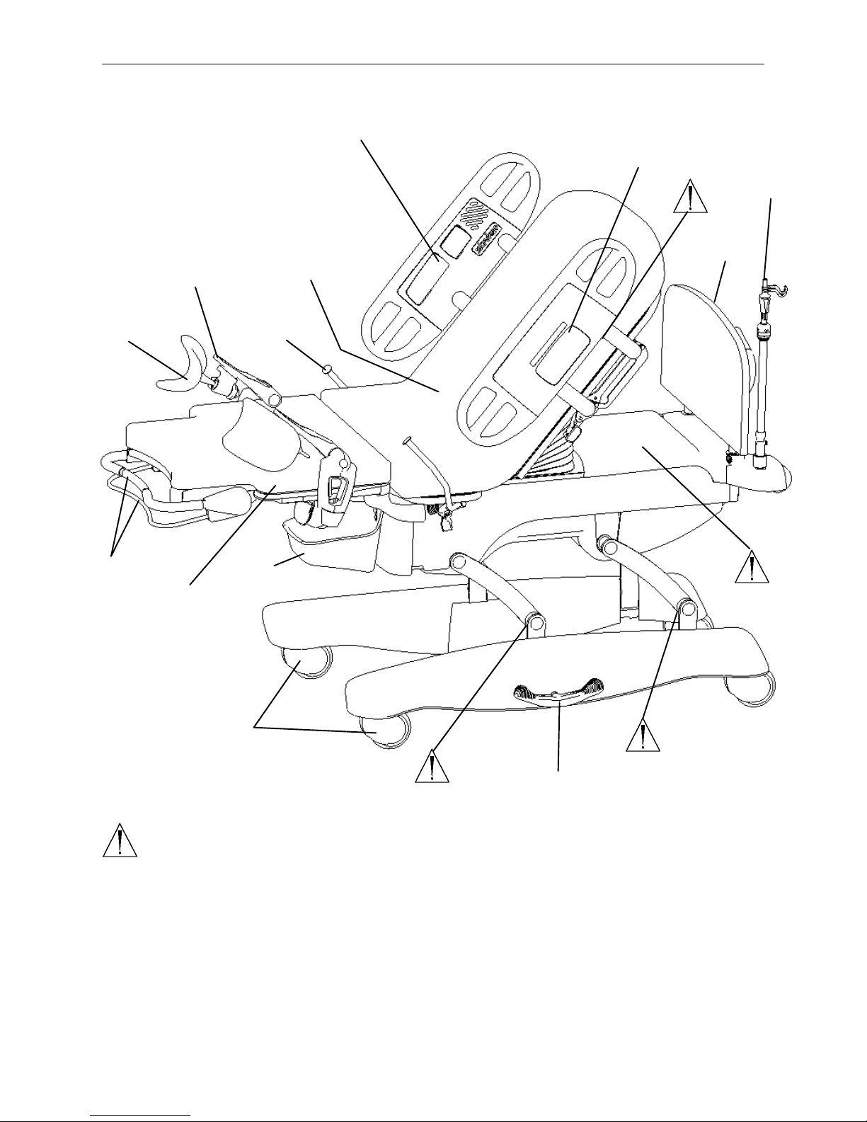
Foot Rest
(1 of 2)
Bed Illustration
Siderail Controls
(Patient Side)
Litter Mattress
Siderail Controls
(Clinical Staff Side)
IV Pole
Head Board
Calf Rest
(1 of 2)
Foot Section
Locking Bar &
Release
Handle
Labor Grip
(1 of 2)
Fluid
Basin
Foot End
Mattress
Casters
(2 of 4)
WARNING
Potential pinch points
Brake/Steer Pedal
(1 of 2)
8
Page 10

Siderail Operation Guide
OPERATING SIDERAILS
To engage the head end siderail, grasp the rail and swing it upward to full height. When the siderail is being
raised, it does not lock in the intermediate position. To lower the siderail, push in the release handle and rotate
the siderail until it locks in the intermediate position. To lower the siderail fully, push in the release handle again
and rotate the siderail until it is completely lowered.
WARNING
When raising the siderails, listen for the ”click” that indicates the siderail has locked in the up position. Pull
firmly on the siderail to ensure it is locked into position. Siderails are not intended to be a patient restraint
device. It is the responsibility of attending medical personnel to determine the degree of restraint and the
siderail positioning necessary to ensure a patient will remain safely in bed. The intermediate position should
be used only to assist the patient during ingress and egress from the bed.
NOTE
To activate the siderail bypass mechanism, the rail must be fully lowered. If the rail is not completely lowered,
the siderail will lock in the intermediate position when it is raised.
USING THE SIDERAIL CONTROL PANEL LIGHTS
The bed is equipped with lights to illuminate the head end siderail control panels and the red
nurse call switches. Five settings are available for the control panel lights. Press the backlight button once to turn on the lights at low intensity , again to change to medium intensity,
a third time to change to high intensity, a fourth to leave just the nurse call light on, and a fifth
time to turn all siderail lights off.
LOCKING OUT THE SIDERAIL CONTROLS
The lock out feature disables the siderail bed motion controls. Lock out buttons are located
on the outside of both siderails. Lock out the bed motion controls by depressing the button
once. The bed motion lockout LED will light. Reactivate the controls by pressing the button
again.
9
Page 11

Siderail Operation Guide
OUTSIDE SIDERAIL CONTROLS
3
5
7
9
10
1
14
2
4
6 8
11
12
13
1. Press to raise the Fowler (back section).
2. Press to lower the Fowler (back section).
3. Press to raise the litter.
4. Press to lower the litter.
5. Press to raise the foot section.
6. Press to lower the foot section.
NOTE
When the bed is at a low height and the foot down button is pressed, the litter may raise automatically to provide adequate clearance. The “BED UP” LED on the siderail will flash to indicate activation.
7. Press to increase the seat depth (optional function).
8. Press to decrease the seat depth (optional function).
NOTE
If the Fowler (back section) angle is below 35, pressing the button to decrease the seat depth will cause
the Fowler to raise to 35 before the seat depth decreases. Once the Fowler (back section) is elevated to
35 or greater, the “SKOOCHER ACTIVE” LED will light and the seat depth can be changed.
10
Page 12

Siderail Operation Guide
OUTSIDE SIDERAIL CONTROLS (CONTINUED)
9. Push to lower the head end of the bed (T rendelenburg position). This function is also used for pelvic tilt.
NOTE
When the bed is at a low height and the Trendelenburg button is pressed, the litter may raise automatically
to provide adequate clearance. The “BED UP” LED on the siderail will flash to indicate activation.
10. Push to raise the head end of the bed and/or return the bed to level.
11. Push repeatedly to toggle the siderail lights to different settings:
A. LOW
B. MEDIUM
C. HIGH
D. NURSE CALL ONLY
E. OFF
12. Press to activate Nurse Call.
13. Push to lock out all bed motion. Push again to unlock. The LED will light when bed motion is locked.
14. Lights when the bed is plugged into the wall socket. Blinks if the Nurse Call battery needs to be replaced.
11
Page 13

Siderail Operation Guide
INSIDE SIDERAIL CONTROLS
1
2
1. Press to raise the foot section.
3
4
5
6a
87
11
12
6b
9
87
10
2. Press to lower the foot section.
3. Press to raise the Fowler (back section).
4. Press to lower the Fowler (back section).
5. Press to activate the Nurse Call (optional function).
6. a. Press to turn on and off the TV or radio and to select a channel (TV/Radio − optional function).
b. Press to turn the TV on and off (Smart TV − optional function).
7. Press to increase the volume of the TV or radio (optional function).
8. Press to decrease the volume of the TV or radio (optional function).
9. Press to change (increase) the TV channel number (optional function).
10. Press to change (decrease) the TV channel number (optional function).
11. Press to turn on the room light. Press again to turn off the room light (optional function).
12. Press to turn on the reading light. Press again to turn off the reading light (optional function).
12
Page 14

Siderail Operation Guide
INSIDE SIDERAIL CONTROLS (CONTINUED)
1
2
5
6
3
1. Press to turn on the reading light. Press again to turn off the reading light (optional function).
2. Press to turn on the room light. Press again to turn off the room light (optional function).
3. Push for more support to the patient’s seat section (optional function).
4. Push for less support to the patient’s seat section (optional function).
5. Push for less support to the patient’s lower back (optional function).
6. Push for more support to the patient’s lower back (optional function).
4
13
Page 15

Communication Pendant Operation Guide
14
Page 16

Motion Pendant Operation Guide
15
Page 17

Motion Pendant with Nurse Call Operation Guide
16
Page 18

Bed Operation
USING THE BRAKE/STEER PEDALS
The brake/steer pedals are located at the center of the base frame on both sides of the bed.
To engage the brakes, fully depress the head end side of the pedal. To disengage the brakes, depress
the foot end side of the pedal until the pedal is in the neutral (level) position.
To engage the steer function, fully depress the foot end of the pedal until the steer wheel engages. To
disengage the steer function, depress the head end side of the pedal until the pedal is in the neutral (level)
position.
NOTE
The steer function locks the foot end, right side caster to make the bed easier to maneuver forward and backward. Put the pedal in the neutral position when maneuvering the bed from side to side.
USING THE MANUAL MOTOR HAND CRANK
CAUTION
To avoid injury, unplug the bed power cord from the wall socket before using the manual hand crank.
A manual override is available for the bed lift and trend motors to allow the caregiver to position the bed when
the power cord is not plugged into the wall socket. Insert the crank into either of the sockets at the head end
of the bed and rotate the crank until the desired bed position is reached.
ACTIVATING INSTANT CPR
The CPR release lever is located at the head section on both sides of the bed. To activate the CPR release,
grasp the lever and squeeze tightly. The Fowler (back section) will lower to the lowest position instantly.
WARNING
The instant CPR release is for emergency use only. Before activating the instant CPR, verify all persons and
equipment are away from the area below and around the Fowler (back section) section of the bed or serious
personal injury or damage to the equipment could occur.
17
Page 19

Bed Operation
REMOVING THE HEAD BOARD
To remove the head board, lift it straight up and off the bed. To replace the head board, align the plastic inserts
on the bottom of the head board with the slots at the head end of the bed and lower the head board until it
completely seats in the slots.
NIGHT LIGHT
The bed is equipped with a night light to illuminate the floor area around the bed. The night light will automatically activate when the light in the room becomes dim enough.
NURSE CALL BATTERY
To prevent a low battery condition when the bed is not plugged in, position the cord out switch at the head
end of the bed to the off position. The switch is identified by the label shown below. If the switch is not positioned as shown below and the bed power cord and pendant cord are unplugged, the life of the back−up battery will be significantly reduced.
If the POWER LED (located on the outside of both siderails) is flashing, the 9V Nurse Call battery needs to
be replaced. The battery is located at the head end of the bed. No tools are required to replace the battery .
Unplug the bed power cord from the wall socket and replace the battery. After replacing the battery, verify
the POWER LED is no longer flashing and operates normally when the different light settings are selected.
Properly dispose of the old battery in accordance with local regulations.
18
Page 20

Bed Operation
USING THE LABOR GRIPS
To position the labor grips, grasp the handle and pull the grip out and up above the mattress until the mechanism locks into position. To lower the grips, pull the lever to release the grip and, as it begins to rotate, release
the lever and lower the grip to the stored position.
USING THE OPTIONAL LABOR BAR
To use the labor bar, insert it into the sockets located on each side of the litter at the pivot point for the foot
pans. The labor bar can be used by the patient to aid with various birthing positions such as squatting or kneeling. The optional Stryker labor bar is rated to support 250 pounds.
OPTIONAL LUMBAR PILLOW AND PERINEAL WEDGE
Use the one−touch lumbar and seat buttons on the siderail to adjust the amount of support given to the
patient’s lumbar and seat areas if the bed is equipped with this option.
NOTE
Be sure the locating pins on the underside of the mattress are inserted in the holes in the metal seat support.
ADJUSTABLE SEAT DEPTH (OPTIONAL)
To accommodate patients of different sizes, the depth of the seat can be adjusted up to 4 inches (from 12.5
to 8.5 inches).
The Fowler (back section) must be raised to a minimum of 35 before the seat depth can be changed.
Once the Fowler (back section) is elevated to 35, the “SKOOCHER ACTIVE” LED on the outside of the
siderail will light and the seat depth can be changed. When the Fowler (back section) is lowered (either
electrically or using the emergency CPR release), the bed will automatically adjust the seat depth to 12.5”.
To reduce seat depth, depress the button on the siderail to move the Fowler (back section) toward
the foot end of the bed. Release the button when the desired seat depth is attained.
To increase seat depth, press the button to move the Fowler (back section) toward the head end
of the bed.
19
Page 21

Bed Operation
REMOVING THE FOOT SECTION
Before removing the foot section, put the foot rests into position above the foot mattress and place the
patient’s feet in the contoured foot rests. To remove the foot section, squeeze the red release handle at
the foot end of the bed and raise the locking bar to the full−up position until it latches in place. The foot
section will now slide straight off the bed.
NOTE
If the foot section mattress is placed with the perineal edge toward the floor, it will stand independently.
To reinstall the foot section of the bed, set the foot mattress back on the bed and slide it straight toward
the main mattress. The locking bar can only be lowered when the foot section is in the “locking zone”,
approximately 2 inches from the main mattress. Squeeze the red release handle and lower the locking
bar into the locked position. As the locking bar is lowered, the gap between the mattresses will narrow
to ease installation. The LD304 foot section is designed to lift and support a 300 pound load.
OPERATING THE GLIDEAWAY FOOT RESTS/ATTACHABLE CALF SUPPORTS
Rotate the foot rest into position by pulling it out and up over the foot end mattress until it clicks into place.
Ensure the foot rest is securely locked in the upright position by grasping and attempting to move it.
After they are in position, the foot rests are adjustable six ways:
1. Abduc t/ Adduc t (pivot ing)
Pivoting in and out allows the clinician to position the patient’s feet and legs at the desired width. To
use the Abduct/Adduct feature, squeeze the gray release handles located at t he foot e n d of t he b ed. Pivot
the foot rest into the desired position and release the handle to lock the foot rest in that position.
NOTE
For emergency situations, the foot rests will pivot to 90 degrees. Hold onto the release handle and pivot
the foot rest out. Beyond 36 degrees the foot rest will not lock into position.
2. In/Out
The in/out motion allows the clinician to adjust the foot rests to comfortably accommodate patients of
different heights. Squeeze either of the two purple triggers at the opening on the foot upright and slide
the foot rest to the desired position. Release the trigger to lock the foot rest in position.
3. Up/Down
The foot end high/low adjustment allows the foot end of the bed to be positioned up to 7” below the top
of the seat mattress to accommodate different sized patients when the foot rests calf supports or l abor b ar
are being used. The foot end high/low adjustment is on the outside siderail cont rols (see page 10)
To switch between the foot rest and calf support positions, press the purple button at the bottom of
the gray footrest and rotate the foot rest to the desired position.
To store the footrests, press the purple button at the bottom of the gray foot support and position the foot
support as shown in the following diagram. The footrest cannot be stowed unless it’s in this position. To
ensure the most effective storage, the calf supports should be positioned inside the storage notch.
Foot Rest Store Position
20
Page 22

Bed Operation
WARNING
Prior to placing weight on the foot section, verify the locking bar has been lowered and locked. The foot section locking bar is not designed for use as a grasping bar or other patient assist device.
BIRTHING BED POSITIONING
Position the patient’s feet in the foot rests.
Raise or lower the foot rests to a position comfortable for the patient.
Remove the foot section and tuck the drape into the fluid basin.
Raise the bed to a comfortable height by pressing the “Bed−Up” control on the siderail and position the
patient’s perineum out and over the edge of the seat section.
DELIVERY TABLE POSITIONING
Slide the patient down to the perineal edge.
Lower the foot section to its lowest position.
Position the attached calf supports and place the patient’s legs in the supports.
TRENDELENBURG POSITIONING
Lower the Fowler (back section) by pressing the control on the siderail or by squeezing the CPR lever. Press
the Trendelenburg button on the siderail or the control pendant to lower the head end of the bed to the desired
angle.
PELVIC TILT
Use the Trendelenburg button on the siderail or the control pendant to provide additional pelvic tilt and comfort
for the patient when the Fowler (back section) is raised.
21
Page 23

Bed Operation
OPERATING THE 3−STAGE PERMANENTLY ATTACHED IV POLE
A
C
C
B
D
A
E
DET AIL OF I.V. POLE LATCH
E
B
D
DET AIL OF I.V. POLE GRIP
NOTE
The 3−stage, permanently atached IV pole can only be installed at the head end of the bed
To use the 3−stage permanently attached IV pole:
1. Lift and pivot the pole from the storage position and push down until it is locked into the receptacle.
2. To raise the height of the pole, pull up on the telescoping portion (A) until it locks into place at its fully raised
position.
3. For a higher IV pole, pull up on section (B). Release section (B) at any desired height and it will lock into
place.
4. Rotate the IV hangers (C) to the desired position and hang the IV bags.
5. To lower the IV pole, push up on the red portion of grip (D) while holding onto section (B) until it lowers.
Turn latch (E) clockwise until section (A) lowers.
CAUTION
To avoid damage, the weight of the IV bags should not exceed 40 pounds.
To avoid damage while transporting the bed, verify the IV pole is at a low enough height to allow it to pass
safely through door openings.
22
Page 24

Cleaning
Hand wash all surfaces of the bed with warm water and mild detergent. DRY THOROUGHLY . D o not steam
clean or hose off the LD304 Birthing Bed. Do not immerse any part of the bed. Some of the internal parts
of the bed are electric and may be damaged by exposure to water.
Suggested cleaners for bed surfaces:
Quaternary Cleaners (active ingredient − ammonium chloride)
Phenolic Cleaners (active ingredient − o−phenyl phenyl)
Chlorinated Bleach Solution (5.25% − less than 1 part bleach to 100 parts water)
Avoid over−saturation and ensure the product does not stay wet longer than the chemical manufacturer’s
guidelines for proper disinfecting.
CAUTION
SOME CLEANING PRODUCTS ARE CORROSIVE IN NATURE AND MAY CAUSE DAMAGE TO THE
PRODUCT IF USED IMPROPERLY. If the products described above are used to clean Stryker patient care
equipment, measures must be taken to insure the beds are wiped with clean water and thoroughly dried following cleaning. Failure to properly rinse and dry the beds will leave a corrosive residue on the surface of
the bed, possibly causing premature corrosion of critical components. Failure to follow the above directions
when using these types of cleaners may void this product’s warranty.
For mattress cleaning and disinfecting, use warm water and a neutral detergent. A sodium hypochlorite solution can also be used for cleaning. If using a chlorinated bleach solution (5.25%) dilute to less than 2 parts
bleach to 100 parts water.
CAUTION
Mattresses must be completely dried after cleaning. Failure to thoroughly rinse and dry mattress surfaces
after cleaning may cause damage to the mattress and may void this product’s warranty.
23
Page 25

Preventative Maintenance Checklist
All fasteners secure
All welds intact, not cracked or broken
No bent or broken tubing or sheet metal
No debris in casters
All casters secure and swivel properly
Engage brake pedal and push on the bed to ensure all casters lock securely
Steer caster latches properly
Siderails move and latch properly
Fowler operates properly
Fowler (back rest) Slide operates properly
Bed Up/Down operates properly
Foot section operates properly
Foot uprights operate properly
Trendelenburg operates properly
IV pole intact and operating properly
No rips or cracks in mattress cover
Lubricate where required
Replace Nurse Call 9V battery (annually)
Power cord not frayed
No cables worn or pinched
All electrical connections tight
All grounds secure to the frame
Ground impedance not more than 100 milliohms
Current leakage not more than 300 microamps
Serial No.
NOTE
Preventative maintenance should be performed at a minimum of annually. A preventative maintenance program should be established for all Stryker Medical equipment. Preventative maintenance may need to be
performed more frequently based on the usage level of the product.
24
Page 26

Warranty
Limited Warranty:
Stryker Medical Division, a division of Stryker Corporation, warrants to the original purchaser that its products
should be free from defects in material and workmanship for a period of one (1) year after date of delivery.
Stryker’s obligation under this warranty is expressly limited to supplying replacement parts and labor for, or
replacing, at its option, any product which is, in the sole discretion of Stryker, found to be defective. Stryker
warrants to the original purchaser that the frame and welds on its beds will be free from structural defects
for as long as the original purchaser owns the bed. If requested by Stryker, products or parts for which a
warranty claim is made shall be returned prepaid to Stryker’s factory. Any improper use or any alteration or
repair by others in such manner as in Stryker’s judgement affects the product materially and adversely shall
void this warranty . Any repair of Stryker products using parts not provided or authorized by Stryker shall void
this warranty. No employee or representative of Stryker is authorized to change this warranty in any way.
Stryker Medical beds are designed for a 15 year expected life under normal use conditions and appropriate
periodic maintenance as described in the maintenance manual for each device.
This statement constitutes Stryker’s entire warranty with respect to the aforesaid equipment. STRYKER
MAKES NO OTHER WARRANTY OR REPRESENTATION, EITHER EXPRESSED OR IMPLIED, EXCEPT
AS SET FORTH HEREIN. THERE IS NO WARRANTY OF MERCHANTABILITY AND THERE ARE NO
WARRANTIES OF FITNESS FOR ANY PARTICULAR PURPOSE. IN NO EVENT SHALL STRYKER BE
LIABLE HEREUNDER FOR INCIDENTAL OR CONSEQUENTIAL DAMAGES ARISING FROM OR IN ANY
MANNER RELATED TO SALES OR USE OF ANY SUCH EQUIPMENT.
To Obtain Parts and Service:
Stryker products are supported by a nationwide network of dedicated Stryker Field Service Representatives.
These representatives are factory trained, available locally, and carry a substantial spare parts inventory to
minimize repair time. Simply call your local representative, or call Stryker Customer Service at (800)
327−0770.
Service Contract Coverage:
Stryker has developed a comprehensive program of service contract options designed to keep your equipment operating at peak performance at the same time it eliminates unexpected costs. We recommend that
these programs be activated before the expiration of the new product warranty to eliminate the potential of
additional equipment upgrade charges.
A SERVICE CONTRACT HELPS TO:
Ensure equipment reliability
Stabilize maintenance budgets
Diminish downtime
Establish documentation for JCAHO
Increase product life
Enhance trade−in value
Address risk management and safety
25
Page 27

Warranty
Stryker offers the following service contract programs:
SPECIFICATIONS GOLD SILVER PM* ONLY
Annually scheduled preventative maintenance X X
All parts,** labor, and travel X X
Unlimited emergency service calls X X
Priority one contact; two hour phone response X X X
Most repairs will be completed within 3 business days X X
JCAHO documentation X X X
On−site log book w/ preventative maintenance & emergency service records X
Factory−trained Stryker Service Technicians X X X
Stryker authorized parts X X X
End of year summary X
Stryker will perform all service during regular business hours (9−5) X X X
* Replacement parts and labor for products under PM contract will be discounted.
** Does not include any disposable items, I.V. poles (except for Stryker HD permanent poles), mattresses, or damage re-
sulting from abuse.
Stryker Medical also offers personalized service contracts.
Pricing is determined by age, location, model and condition of product.
For more information on our service contracts,
please call your local representative or call (800) 327−0770 (option #2).
Return Authorization:
Merchandise cannot be returned without approval from the Stryker Customer Service Department. An authorization number will be provided which must be printed on the returned merchandise. Stryker reserves the
right to charge shipping and restocking fees on returned items.
SPECIAL, MODIFIED, OR DISCONTINUED ITEMS NOT SUBJECT TO RETURN.
Damaged Merchandise:
ICC Regulations require that claims for damaged merchandise must be made with the carrier within fifteen
(15) days of receipt of merchandise. DO NOT ACCEPT DAMAGED SHIPMENTS UNLESS SUCH DAMAGE
IS NOTED ON THE DELIVERY RECEIPT AT THE TIME OF RECEIPT. Upon prompt notification, Stryker
will file a freight claim with the appropriate carrier for damages incurred. Claim will be limited in amount to
the actual replacement cost. In the event that this information is not received by Stryker within the fifteen
(15) day period following the delivery of the merchandise, or the damage was not noted on the delivery receipt
at the time of receipt, the customer will be responsible for payment of the original invoice in full.
Claims for any short shipment must be made within thirty (30) days of invoice.
International Warranty Clause:
This warranty reflects U.S. domestic policy. Warranty outside the U.S. may vary by country. Please contact
your local Stryker Medical representative for additional information.
26
Page 28

European Representative
Stryker EMEA RA/QA Director
Stryker France
ZAC Satolas Green Pusignan
Av. De Satolas Green
69881 MEYZIEU Cedex
France
6300 S. Sprinkle Road, Kalamazoo, MI 49001−9799
(800) 327−0770
www.strykermedical.com
JH 7/05 4701−009−001 REV D
 Loading...