

Page 1

Birthing Bed
Model LD304
Maintenance Manual
For Parts or Technical Assistance:
USA: 1-800-327-0770 (option 2)
Canada: 1-888-233-6888
2007/01 4701-109-002 REV C www.stryker.com
Page 2

Page 3

Table of Contents
Introduction . . . . . . . . . . . . . . . . . . . . . . . . . . . . . . . . . . . . . . . . . . . . . . . . . . . . . . . . . . . . . . . . . . . . . . . . . . . . . . 7
Intended Use . . . . . . . . . . . . . . . . . . . . . . . . . . . . . . . . . . . . . . . . . . . . . . . . . . . . . . . . . . . . . . . . . . . . . . . . . . 7
Product Description . . . . . . . . . . . . . . . . . . . . . . . . . . . . . . . . . . . . . . . . . . . . . . . . . . . . . . . . . . . . . . . . . . . . . 7
Product Illustration . . . . . . . . . . . . . . . . . . . . . . . . . . . . . . . . . . . . . . . . . . . . . . . . . . . . . . . . . . . . . . . . . . . . . . 7
Specifications . . . . . . . . . . . . . . . . . . . . . . . . . . . . . . . . . . . . . . . . . . . . . . . . . . . . . . . . . . . . . . . . . . . . . . . . . 8
Warning / Caution / Note Definition. . . . . . . . . . . . . . . . . . . . . . . . . . . . . . . . . . . . . . . . . . . . . . . . . . . . . . . . . . 9
Symbols . . . . . . . . . . . . . . . . . . . . . . . . . . . . . . . . . . . . . . . . . . . . . . . . . . . . . . . . . . . . . . . . . . . . . . . . . . . . . . . . 10
Summary of Safety Precautions . . . . . . . . . . . . . . . . . . . . . . . . . . . . . . . . . . . . . . . . . . . . . . . . . . . . . . . . . . . . . . 11
Safety Tips and Guidelines. . . . . . . . . . . . . . . . . . . . . . . . . . . . . . . . . . . . . . . . . . . . . . . . . . . . . . . . . . . . . . . 11
Preventative Maintenance . . . . . . . . . . . . . . . . . . . . . . . . . . . . . . . . . . . . . . . . . . . . . . . . . . . . . . . . . . . . . . . . . . . 13
Cleaning . . . . . . . . . . . . . . . . . . . . . . . . . . . . . . . . . . . . . . . . . . . . . . . . . . . . . . . . . . . . . . . . . . . . . . . . . . . . . . . 14
Troubleshooting Guide . . . . . . . . . . . . . . . . . . . . . . . . . . . . . . . . . . . . . . . . . . . . . . . . . . . . . . . . . . . . . . . . . . . . . 15
Quick Reference Replacement Parts List . . . . . . . . . . . . . . . . . . . . . . . . . . . . . . . . . . . . . . . . . . . . . . . . . . . . . . . 21
Electrical Service Information . . . . . . . . . . . . . . . . . . . . . . . . . . . . . . . . . . . . . . . . . . . . . . . . . . . . . . . . . . . . . . . . 23
Bed Circuit Boards - CPU Board - 3002-407-950 . . . . . . . . . . . . . . . . . . . . . . . . . . . . . . . . . . . . . . . . . . . . . . 23
Bed Circuit Boards - Software Configuration . . . . . . . . . . . . . . . . . . . . . . . . . . . . . . . . . . . . . . . . . . . . . . . . . . 25
Bed Circuit Boards - Power Supply - 0059-157-000. . . . . . . . . . . . . . . . . . . . . . . . . . . . . . . . . . . . . . . . . . . . . 26
Bed Circuit Boards - Foot Power Board - 4701-080-053 . . . . . . . . . . . . . . . . . . . . . . . . . . . . . . . . . . . . . . . . . 27
Optional Bed Communications Tester - 3002-045-700. . . . . . . . . . . . . . . . . . . . . . . . . . . . . . . . . . . . . . . . . . . 28
Head Wall Output Configuration . . . . . . . . . . . . . . . . . . . . . . . . . . . . . . . . . . . . . . . . . . . . . . . . . . . . . . . . . . . 29
Service Information. . . . . . . . . . . . . . . . . . . . . . . . . . . . . . . . . . . . . . . . . . . . . . . . . . . . . . . . . . . . . . . . . . . . . . . . 30
Static Discharge Precautions . . . . . . . . . . . . . . . . . . . . . . . . . . . . . . . . . . . . . . . . . . . . . . . . . . . . . . . . . . . . . 30
CPU Board Replacement (3002-407-950) . . . . . . . . . . . . . . . . . . . . . . . . . . . . . . . . . . . . . . . . . . . . . . . . . . . . 31
Power Supply Replacement (0059-157-000) . . . . . . . . . . . . . . . . . . . . . . . . . . . . . . . . . . . . . . . . . . . . . . . . . . 31
Foot Power Board Replacement (4701-080-053) . . . . . . . . . . . . . . . . . . . . . . . . . . . . . . . . . . . . . . . . . . . . . . . 32
Brake Adjustment. . . . . . . . . . . . . . . . . . . . . . . . . . . . . . . . . . . . . . . . . . . . . . . . . . . . . . . . . . . . . . . . . . . . . . 32
Bed Lift Motor Replacement (120V - 4701-700-005) . . . . . . . . . . . . . . . . . . . . . . . . . . . . . . . . . . . . . . . . . . . . 33
Trendelenburg Motor Replacement (120V - 4701-032-095) . . . . . . . . . . . . . . . . . . . . . . . . . . . . . . . . . . . . . . . 34
Fowler Motor Replacement (120V - 4701-035-040) . . . . . . . . . . . . . . . . . . . . . . . . . . . . . . . . . . . . . . . . . . . . . 36
Fowler Ball Screw Replacement (4701-035-012) . . . . . . . . . . . . . . . . . . . . . . . . . . . . . . . . . . . . . . . . . . . . . . . 37
Skoocher™ Motor Replacement . . . . . . . . . . . . . . . . . . . . . . . . . . . . . . . . . . . . . . . . . . . . . . . . . . . . . . . . . . . 38
Foot Motor Replacement (120V - 4701-040-035 / 230V - 4712-040-035) . . . . . . . . . . . . . . . . . . . . . . . . . . . . . 39
Optional Air Mattress Compressor Replacement (120V - 4701-048-015 / 230V - 4712-048-015) . . . . . . . . . . . . 40
Night Light Replacement (4701-080-080) . . . . . . . . . . . . . . . . . . . . . . . . . . . . . . . . . . . . . . . . . . . . . . . . . . . . 41
Nurse Call 9V Battery Replacement . . . . . . . . . . . . . . . . . . . . . . . . . . . . . . . . . . . . . . . . . . . . . . . . . . . . . . . . 41
Diagnostics Mode . . . . . . . . . . . . . . . . . . . . . . . . . . . . . . . . . . . . . . . . . . . . . . . . . . . . . . . . . . . . . . . . . . . . . 41
Foot Potentiometer Replacement . . . . . . . . . . . . . . . . . . . . . . . . . . . . . . . . . . . . . . . . . . . . . . . . . . . . . . . . . . 42
Foot Potentiometer Burn-In Procedure . . . . . . . . . . . . . . . . . . . . . . . . . . . . . . . . . . . . . . . . . . . . . . . . . . . . . . 43
Fowler Potentiometer Replacement (4701-080-025) . . . . . . . . . . . . . . . . . . . . . . . . . . . . . . . . . . . . . . . . . . . . 44
Fowler Potentiometer Burn-In Procedure. . . . . . . . . . . . . . . . . . . . . . . . . . . . . . . . . . . . . . . . . . . . . . . . . . . . . 44
Lift Potentiometer Replacement (4701-080-025) . . . . . . . . . . . . . . . . . . . . . . . . . . . . . . . . . . . . . . . . . . . . . . . 45
Lift Potentiometer Burn-In Procedure . . . . . . . . . . . . . . . . . . . . . . . . . . . . . . . . . . . . . . . . . . . . . . . . . . . . . . . 45
Smart TV Interface Burn-in Procedure . . . . . . . . . . . . . . . . . . . . . . . . . . . . . . . . . . . . . . . . . . . . . . . . . . . . . . 46
www.stryker.com 4701-109- 002 REV C 3
Page 4

Table of Contents
Asembly Drawings
6” Caster/Base Assembly. . . . . . . . . . . . . . . . . . . . . . . . . . . . . . . . . . . . . . . . . . . . . . . . . . . . . . . . . . . . . . . . 47
8” Caster/Base Assembly. . . . . . . . . . . . . . . . . . . . . . . . . . . . . . . . . . . . . . . . . . . . . . . . . . . . . . . . . . . . . . . . 48
6” Caster Assembly - 3001-200-060 . . . . . . . . . . . . . . . . . . . . . . . . . . . . . . . . . . . . . . . . . . . . . . . . . . . . . . . . 49
6” Steer Caster Assembly - 3001-200-050 . . . . . . . . . . . . . . . . . . . . . . . . . . . . . . . . . . . . . . . . . . . . . . . . . . . 50
6” Molded Wheel Assembly - 5000-002-010 . . . . . . . . . . . . . . . . . . . . . . . . . . . . . . . . . . . . . . . . . . . . . . . . . . 51
Optional 8” Caster Assembly - 3001-200-090 . . . . . . . . . . . . . . . . . . . . . . . . . . . . . . . . . . . . . . . . . . . . . . . . . 52
Optional 8” Steer Caster Assembly - 3001-200-080 . . . . . . . . . . . . . . . . . . . . . . . . . . . . . . . . . . . . . . . . . . . . 53
Optional 8” Wheel Assembly - 0715-002-025 . . . . . . . . . . . . . . . . . . . . . . . . . . . . . . . . . . . . . . . . . . . . . . . . . 54
Base Assembly . . . . . . . . . . . . . . . . . . . . . . . . . . . . . . . . . . . . . . . . . . . . . . . . . . . . . . . . . . . . . . . . . . . . . . . 55
Head End Brake Assembly, Right . . . . . . . . . . . . . . . . . . . . . . . . . . . . . . . . . . . . . . . . . . . . . . . . . . . . . . . . . . 60
Head End Brake Assembly, Left . . . . . . . . . . . . . . . . . . . . . . . . . . . . . . . . . . . . . . . . . . . . . . . . . . . . . . . . . . 61
Foot End Brake Assembly, Right. . . . . . . . . . . . . . . . . . . . . . . . . . . . . . . . . . . . . . . . . . . . . . . . . . . . . . . . . . . 62
Foot End Brake Assembly, Left. . . . . . . . . . . . . . . . . . . . . . . . . . . . . . . . . . . . . . . . . . . . . . . . . . . . . . . . . . . . 63
Litter Lift/Trend Assembly . . . . . . . . . . . . . . . . . . . . . . . . . . . . . . . . . . . . . . . . . . . . . . . . . . . . . . . . . . . . . . . 64
Litter/Lift/Trend Standard Components . . . . . . . . . . . . . . . . . . . . . . . . . . . . . . . . . . . . . . . . . . . . . . . . . . . . . . 69
Domestic Trend Motor Assembly . . . . . . . . . . . . . . . . . . . . . . . . . . . . . . . . . . . . . . . . . . . . . . . . . . . . . . . . . . 74
International Trend Motor Assembly . . . . . . . . . . . . . . . . . . . . . . . . . . . . . . . . . . . . . . . . . . . . . . . . . . . . . . . . 76
Bed Lift Motor Assembly . . . . . . . . . . . . . . . . . . . . . . . . . . . . . . . . . . . . . . . . . . . . . . . . . . . . . . . . . . . . . . . . 79
Bed Lift Standard Components. . . . . . . . . . . . . . . . . . . . . . . . . . . . . . . . . . . . . . . . . . . . . . . . . . . . . . . . . . . . 80
Foot Lift Assembly . . . . . . . . . . . . . . . . . . . . . . . . . . . . . . . . . . . . . . . . . . . . . . . . . . . . . . . . . . . . . . . . . . . . . 85
Foot Lift Assembly Standard Components. . . . . . . . . . . . . . . . . . . . . . . . . . . . . . . . . . . . . . . . . . . . . . . . . . . . 86
Litter Assembly . . . . . . . . . . . . . . . . . . . . . . . . . . . . . . . . . . . . . . . . . . . . . . . . . . . . . . . . . . . . . . . . . . . . . . . 89
Seat Assembly. . . . . . . . . . . . . . . . . . . . . . . . . . . . . . . . . . . . . . . . . . . . . . . . . . . . . . . . . . . . . . . . . . . . . . . 101
Left Hand Grip Assembly - 5010-230-061 . . . . . . . . . . . . . . . . . . . . . . . . . . . . . . . . . . . . . . . . . . . . . . . . . . . 102
Right Hand Grip Assembly - 5010-230-060 . . . . . . . . . . . . . . . . . . . . . . . . . . . . . . . . . . . . . . . . . . . . . . . . . . 103
Bellows Cover Assembly - 4701-030-130 . . . . . . . . . . . . . . . . . . . . . . . . . . . . . . . . . . . . . . . . . . . . . . . . . . . 104
Plastic Fluid Basin - 4701-036-001 . . . . . . . . . . . . . . . . . . . . . . . . . . . . . . . . . . . . . . . . . . . . . . . . . . . . . . . . 105
Night Light Option Assembly - 4701-036-201. . . . . . . . . . . . . . . . . . . . . . . . . . . . . . . . . . . . . . . . . . . . . . . . . 106
Foot Positioning Assembly . . . . . . . . . . . . . . . . . . . . . . . . . . . . . . . . . . . . . . . . . . . . . . . . . . . . . . . . . . . . . . 108
Foot Positioning Subassembly, Left . . . . . . . . . . . . . . . . . . . . . . . . . . . . . . . . . . . . . . . . . . . . . . . . . . . . . . . 110
Foot Positioning Subassembly, Right. . . . . . . . . . . . . . . . . . . . . . . . . . . . . . . . . . . . . . . . . . . . . . . . . . . . . . . 112
Foot Lift Casting Subassembly - 4701-040-205 . . . . . . . . . . . . . . . . . . . . . . . . . . . . . . . . . . . . . . . . . . . . . . . 114
Skoocher™ Option Assembly . . . . . . . . . . . . . . . . . . . . . . . . . . . . . . . . . . . . . . . . . . . . . . . . . . . . . . . . . . . . 115
Non-Skoocher™ Option . . . . . . . . . . . . . . . . . . . . . . . . . . . . . . . . . . . . . . . . . . . . . . . . . . . . . . . . . . . . . . . . 120
Fowler Guide/Skoocher™ Standard Components . . . . . . . . . . . . . . . . . . . . . . . . . . . . . . . . . . . . . . . . . . . . . 122
Domestic Fowler/Skoocher™ Motor - 4701-035-040 . . . . . . . . . . . . . . . . . . . . . . . . . . . . . . . . . . . . . . . . . . . 130
International Fowler/Skoocher™ Motor - 4712-035-040. . . . . . . . . . . . . . . . . . . . . . . . . . . . . . . . . . . . . . . . . 130
Domestic Fowler Motor W/Clutch . . . . . . . . . . . . . . . . . . . . . . . . . . . . . . . . . . . . . . . . . . . . . . . . . . . . . . . . . 131
International Fowler Motor W/Clutch . . . . . . . . . . . . . . . . . . . . . . . . . . . . . . . . . . . . . . . . . . . . . . . . . . . . . . 131
Foot Section Assembly. . . . . . . . . . . . . . . . . . . . . . . . . . . . . . . . . . . . . . . . . . . . . . . . . . . . . . . . . . . . . . . . . 132
Foot Section Standard Components - 4701-040-005 . . . . . . . . . . . . . . . . . . . . . . . . . . . . . . . . . . . . . . . . . . . 133
Sliding Block Assembly . . . . . . . . . . . . . . . . . . . . . . . . . . . . . . . . . . . . . . . . . . . . . . . . . . . . . . . . . . . . . . . . 139
4 4701-109- 002 REV C www.stryker.com
Page 5

Table of Contents
Assembly Drawings (Continued)
Foot Mattress . . . . . . . . . . . . . . . . . . . . . . . . . . . . . . . . . . . . . . . . . . . . . . . . . . . . . . . . . . . . . . . . . . . . . . . 142
Enhanced Comfort Mattress Option . . . . . . . . . . . . . . . . . . . . . . . . . . . . . . . . . . . . . . . . . . . . . . . . . . . . . . . 143
Enhanced Comfort Mattress. . . . . . . . . . . . . . . . . . . . . . . . . . . . . . . . . . . . . . . . . . . . . . . . . . . . . . . . . . . . . 144
Enhanced Comfort Mattress Standard Components . . . . . . . . . . . . . . . . . . . . . . . . . . . . . . . . . . . . . . . . . . . 145
Air Mattress Option . . . . . . . . . . . . . . . . . . . . . . . . . . . . . . . . . . . . . . . . . . . . . . . . . . . . . . . . . . . . . . . . . . . 146
Air Mattress . . . . . . . . . . . . . . . . . . . . . . . . . . . . . . . . . . . . . . . . . . . . . . . . . . . . . . . . . . . . . . . . . . . . . . . . . 147
Optional Air Mattress Standard Components. . . . . . . . . . . . . . . . . . . . . . . . . . . . . . . . . . . . . . . . . . . . . . . . . 148
Air Mattress Compressor / Manifold Assembly . . . . . . . . . . . . . . . . . . . . . . . . . . . . . . . . . . . . . . . . . . . . . . . 150
Left Upright Assembly . . . . . . . . . . . . . . . . . . . . . . . . . . . . . . . . . . . . . . . . . . . . . . . . . . . . . . . . . . . . . . . . . 152
Right Upright Assembly . . . . . . . . . . . . . . . . . . . . . . . . . . . . . . . . . . . . . . . . . . . . . . . . . . . . . . . . . . . . . . . . 155
Foot Assembly, Left & Right . . . . . . . . . . . . . . . . . . . . . . . . . . . . . . . . . . . . . . . . . . . . . . . . . . . . . . . . . . . . . 158
Upright Housing Assembly . . . . . . . . . . . . . . . . . . . . . . . . . . . . . . . . . . . . . . . . . . . . . . . . . . . . . . . . . . . . . . 159
Upright Housing . . . . . . . . . . . . . . . . . . . . . . . . . . . . . . . . . . . . . . . . . . . . . . . . . . . . . . . . . . . . . . . . . . . . . . 163
Foot Abduction Extrusion Assembly . . . . . . . . . . . . . . . . . . . . . . . . . . . . . . . . . . . . . . . . . . . . . . . . . . . . . . . 164
Left Upright Slide Assembly . . . . . . . . . . . . . . . . . . . . . . . . . . . . . . . . . . . . . . . . . . . . . . . . . . . . . . . . . . . . . 166
Right Upright Slide Assembly . . . . . . . . . . . . . . . . . . . . . . . . . . . . . . . . . . . . . . . . . . . . . . . . . . . . . . . . . . . . 167
Left Abduction Assembly . . . . . . . . . . . . . . . . . . . . . . . . . . . . . . . . . . . . . . . . . . . . . . . . . . . . . . . . . . . . . . . 168
Right Abduction Assembly . . . . . . . . . . . . . . . . . . . . . . . . . . . . . . . . . . . . . . . . . . . . . . . . . . . . . . . . . . . . . . 169
Abduction Assembly Standard Components . . . . . . . . . . . . . . . . . . . . . . . . . . . . . . . . . . . . . . . . . . . . . . . . . 170
No Calf Support Option - 4701-040-185 . . . . . . . . . . . . . . . . . . . . . . . . . . . . . . . . . . . . . . . . . . . . . . . . . . . . 172
Attached Support Calf Option - 4701-840-290 . . . . . . . . . . . . . . . . . . . . . . . . . . . . . . . . . . . . . . . . . . . . . . . 173
Right Attached Calf Support Assembly - 4701-840-270 . . . . . . . . . . . . . . . . . . . . . . . . . . . . . . . . . . . . . . . . . 174
Left Attached Calf Support Assembly - 4701-840-275 . . . . . . . . . . . . . . . . . . . . . . . . . . . . . . . . . . . . . . . . . . 175
Removable Calf Support Option - 4701-840-295 . . . . . . . . . . . . . . . . . . . . . . . . . . . . . . . . . . . . . . . . . . . . . . 176
Removable Calf Support Assembly, Right & Left . . . . . . . . . . . . . . . . . . . . . . . . . . . . . . . . . . . . . . . . . . . . . . 177
No Optional Headwall Interface . . . . . . . . . . . . . . . . . . . . . . . . . . . . . . . . . . . . . . . . . . . . . . . . . . . . . . . . . . 178
Headwall Interface with Pendant Port/No Nurse Call . . . . . . . . . . . . . . . . . . . . . . . . . . . . . . . . . . . . . . . . . . . 180
Headwall Interface with Nurse Call/No Pendant Port . . . . . . . . . . . . . . . . . . . . . . . . . . . . . . . . . . . . . . . . . . . 182
Headwall Interface with Nurse Call & Pendant Port . . . . . . . . . . . . . . . . . . . . . . . . . . . . . . . . . . . . . . . . . . . . 184
Electrical Box Standard Components . . . . . . . . . . . . . . . . . . . . . . . . . . . . . . . . . . . . . . . . . . . . . . . . . . . . . . 186
Full Bed Electrical Assembly . . . . . . . . . . . . . . . . . . . . . . . . . . . . . . . . . . . . . . . . . . . . . . . . . . . . . . . . . . . . 189
Left Siderail Assembly . . . . . . . . . . . . . . . . . . . . . . . . . . . . . . . . . . . . . . . . . . . . . . . . . . . . . . . . . . . . . . . . . 193
Standard Siderail Components, Left - 4701-020-085 . . . . . . . . . . . . . . . . . . . . . . . . . . . . . . . . . . . . . . . . . . . 194
Right Siderail Assembly . . . . . . . . . . . . . . . . . . . . . . . . . . . . . . . . . . . . . . . . . . . . . . . . . . . . . . . . . . . . . . . . 198
Standard Siderail Components, Right - 4701-020-090 . . . . . . . . . . . . . . . . . . . . . . . . . . . . . . . . . . . . . . . . . . 199
Siderail Latch Assembly, Left - 3002-400-070. . . . . . . . . . . . . . . . . . . . . . . . . . . . . . . . . . . . . . . . . . . . . . . . 203
Siderail Latch Assembly, Right - 3002-400-075 . . . . . . . . . . . . . . . . . . . . . . . . . . . . . . . . . . . . . . . . . . . . . . . 204
Siderail Bypass Detent Clip Assembly - 3002-400-090 . . . . . . . . . . . . . . . . . . . . . . . . . . . . . . . . . . . . . . . . . 205
Siderail Timing Link Ass’y, Head End, Right - 4700-320-004 . . . . . . . . . . . . . . . . . . . . . . . . . . . . . . . . . . . . . 206
Siderail Timing Link Ass’y, Head End, Left - 4700-320-005 . . . . . . . . . . . . . . . . . . . . . . . . . . . . . . . . . . . . . . 207
Siderail Release Lever Assembly, Right . . . . . . . . . . . . . . . . . . . . . . . . . . . . . . . . . . . . . . . . . . . . . . . . . . . . 208
Siderail Release Lever Assembly, Left . . . . . . . . . . . . . . . . . . . . . . . . . . . . . . . . . . . . . . . . . . . . . . . . . . . . . 209
www.stryker.com 4701-109- 002 REV C 5
Page 6

Table of Contents
Assembly Drawings (Continued)
Standard Siderail Assembly . . . . . . . . . . . . . . . . . . . . . . . . . . . . . . . . . . . . . . . . . . . . . . . . . . . . . . . . . . . . . 210
Siderail Assembly, with Nurse Call . . . . . . . . . . . . . . . . . . . . . . . . . . . . . . . . . . . . . . . . . . . . . . . . . . . . . . . . 213
Siderail Assembly, with Lumbar . . . . . . . . . . . . . . . . . . . . . . . . . . . . . . . . . . . . . . . . . . . . . . . . . . . . . . . . . . 216
Siderail Assembly, with Skoocher™ . . . . . . . . . . . . . . . . . . . . . . . . . . . . . . . . . . . . . . . . . . . . . . . . . . . . . . . 219
Siderail Assembly, with Skoocher™ and Nurse Call . . . . . . . . . . . . . . . . . . . . . . . . . . . . . . . . . . . . . . . . . . . . 222
Siderail Assembly, with Lumbar and Nurse Call . . . . . . . . . . . . . . . . . . . . . . . . . . . . . . . . . . . . . . . . . . . . . . . 225
Siderail Assembly, with Skoocher™ and Lumbar . . . . . . . . . . . . . . . . . . . . . . . . . . . . . . . . . . . . . . . . . . . . . . 228
Siderail Assembly with Skoocher™/Nurse Call/Lumbar . . . . . . . . . . . . . . . . . . . . . . . . . . . . . . . . . . . . . . . . . 231
Siderail Assembly with Nurse Call, TV/Radio & Lights . . . . . . . . . . . . . . . . . . . . . . . . . . . . . . . . . . . . . . . . . . 234
Siderail Assembly with Nurse Call/Smart TV/Lights . . . . . . . . . . . . . . . . . . . . . . . . . . . . . . . . . . . . . . . . . . . . 237
Siderail with Nurse Call, TV/Radio, Lights & Lumbar . . . . . . . . . . . . . . . . . . . . . . . . . . . . . . . . . . . . . . . . . . . 240
Siderail with Nurse Call/Smart TV/Lights & Lumbar . . . . . . . . . . . . . . . . . . . . . . . . . . . . . . . . . . . . . . . . . . . . 243
Siderail with Skoocher™, Nurse Call, TV/Radio & Lights . . . . . . . . . . . . . . . . . . . . . . . . . . . . . . . . . . . . . . . . 246
Siderail with Skoocher/Nurse Call/Smart TV/Lights . . . . . . . . . . . . . . . . . . . . . . . . . . . . . . . . . . . . . . . . . . . . 249
Siderail W/ Skoocher™, NC, TV/Radio, Lights & Lumbar . . . . . . . . . . . . . . . . . . . . . . . . . . . . . . . . . . . . . . . . 252
Siderail W/ Skoocher™/ NC / Smart TV / Lights / Lumbar . . . . . . . . . . . . . . . . . . . . . . . . . . . . . . . . . . . . . . . 255
Outer Siderail Panel, W/O Nurse Call - 4700-020-011 . . . . . . . . . . . . . . . . . . . . . . . . . . . . . . . . . . . . . . . . . . 258
Outer Siderail Panel, with Nurse Call - 4700-020-009 . . . . . . . . . . . . . . . . . . . . . . . . . . . . . . . . . . . . . . . . . . 259
Optional Siderail Lumbar Module, Left - 5000-220-008 . . . . . . . . . . . . . . . . . . . . . . . . . . . . . . . . . . . . . . . . . 260
Optional Siderail Lumbar Module, Right - 5000-220-010 . . . . . . . . . . . . . . . . . . . . . . . . . . . . . . . . . . . . . . . . 261
Siderail Smart TV Module, Left - 5000-020-028 . . . . . . . . . . . . . . . . . . . . . . . . . . . . . . . . . . . . . . . . . . . . . . 262
Siderail Smart TV Module, Right - 5000-020-029 . . . . . . . . . . . . . . . . . . . . . . . . . . . . . . . . . . . . . . . . . . . . . 263
Siderail TV/Lumbar Module, Left - 5000-020-026 . . . . . . . . . . . . . . . . . . . . . . . . . . . . . . . . . . . . . . . . . . . . . 264
Siderail TV/Lumbar Module, Right - 5000-020-027 . . . . . . . . . . . . . . . . . . . . . . . . . . . . . . . . . . . . . . . . . . . . 265
Wood Head Board Mounting Hardware - 4701-030-125 . . . . . . . . . . . . . . . . . . . . . . . . . . . . . . . . . . . . . . . . . 266
Crank Handle Assembly - 4701-036-020. . . . . . . . . . . . . . . . . . . . . . . . . . . . . . . . . . . . . . . . . . . . . . . . . . . . 267
Optional Labor Bar Assembly - 4701-036-010. . . . . . . . . . . . . . . . . . . . . . . . . . . . . . . . . . . . . . . . . . . . . . . . 268
3-Stage I.V. Assembly - 4701-036-035 . . . . . . . . . . . . . . . . . . . . . . . . . . . . . . . . . . . . . . . . . . . . . . . . . . . . . 269
3-Stage I.V. Pole Assembly - 1211-211-010 . . . . . . . . . . . . . . . . . . . . . . . . . . . . . . . . . . . . . . . . . . . . . . . . . . 270
3-Stage IV Pole 3rd Stage Assembly . . . . . . . . . . . . . . . . . . . . . . . . . . . . . . . . . . . . . . . . . . . . . . . . . . . . . . 271
I.V. Pole Latch Assembly - 1211-210-026 . . . . . . . . . . . . . . . . . . . . . . . . . . . . . . . . . . . . . . . . . . . . . . . . . . . . 272
Optional Mattress Overlay - 4701-045-020 . . . . . . . . . . . . . . . . . . . . . . . . . . . . . . . . . . . . . . . . . . . . . . . . . . 273
Warranty . . . . . . . . . . . . . . . . . . . . . . . . . . . . . . . . . . . . . . . . . . . . . . . . . . . . . . . . . . . . . . . . . . . . . . . . . . . . . . 274
Limited Warranty . . . . . . . . . . . . . . . . . . . . . . . . . . . . . . . . . . . . . . . . . . . . . . . . . . . . . . . . . . . . . . . . . . . . . 274
To Obtain Parts and Service . . . . . . . . . . . . . . . . . . . . . . . . . . . . . . . . . . . . . . . . . . . . . . . . . . . . . . . . . . . . 274
Service Contract Coverage . . . . . . . . . . . . . . . . . . . . . . . . . . . . . . . . . . . . . . . . . . . . . . . . . . . . . . . . . . . . . 274
Service Contract Programs . . . . . . . . . . . . . . . . . . . . . . . . . . . . . . . . . . . . . . . . . . . . . . . . . . . . . . . . . . . . . 275
Return Authorization. . . . . . . . . . . . . . . . . . . . . . . . . . . . . . . . . . . . . . . . . . . . . . . . . . . . . . . . . . . . . . . . . . . 275
Damaged Merchandise . . . . . . . . . . . . . . . . . . . . . . . . . . . . . . . . . . . . . . . . . . . . . . . . . . . . . . . . . . . . . . . . 275
International Warranty Clause. . . . . . . . . . . . . . . . . . . . . . . . . . . . . . . . . . . . . . . . . . . . . . . . . . . . . . . . . . . . 275
6 4701-109- 002 REV C www.stryker.com
Page 7
0−8
0−70
17.5
35.5
37
93
81
33
Introduction
INTENDED USE
This manual is designed to assist you with the maintenance of the LD304 Birthing Bed. Read it thoroughly before using
the equipment or beginning any maintenance on it.
PRODUCT DESCRIPTION
This product is an electrically operated maternity bed designed for general patient care use. Major functions include:
Raising and lowering of the litter, raising and lowering of the head and foot end portions and Trendelenburg-like
function.
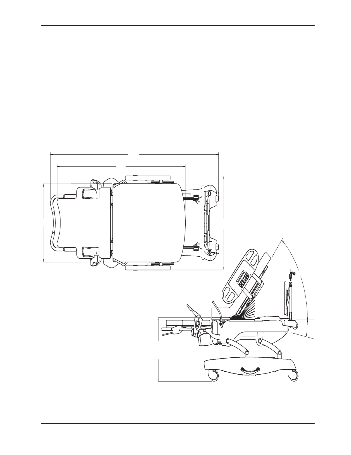
PRODUCT ILLUSTRATION
Return To Table of Contents
www.stryker.com 4701-109- 002 REV C 7
Page 8
SPECIFICATIONS
Introduction
Safe Working Load
Weight of Product 475 pounds, standard configuration
Bed Length/Width 93” x 41” (with siderails up)
Bed Height (to top of seat) Low - 17.5” High / - 35.5” W/6” Casters 44 cm High / - 90 cm W/6” Casters
Mattress Size Head - 49.5” x 33” x 5”
Caster Size 6” Standard; 8” Optional
Critical Angles Maximum Elevation - Head 70°, Trendelenburg 8°,
Foot Section Height Foot Section Travel - 0” up / 7” down Foot Section Travel - 0 cm up
Break-Away Point from Wall 60” 152 cm
Electrical Standard 4 motors function: Head-Bed-Foot-Trendelenburg
Rated Duty Cycle 5% / hr (Continuous Operation with Short-Time Loading)
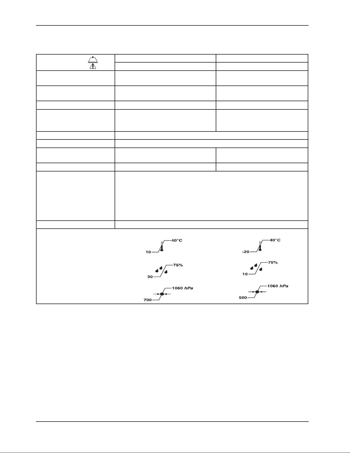
Environmental Conditions Operation Storage and Transportation
Temperature
500 pounds 227 kilograms
250 pounds (Foot Section) 113.4 kilograms (Foot Section)
215 kilograms
525 pounds, all options/accessories
- 37” (with siderails down)
Foot - 30” x 30” x 3”
Patient Sleep Surface - 81”
120 VAC, 60 Hz, 10 Amp
Optional: 230 VAC, ~ 50/60 Hz, 10 Amp
Current leakage less than 300 microamperes (per UL 60601-1).
Hospital grade plug and 3-wire heavy duty cord.
Compatible with non-flammable anesthetic agents and oxygen by nasal catheter
or mask type.
238 kilograms
236 cm x 104 cm (with siderails
up) - 94 cm (with siderails down)
Head -126 cm x 84 cm x 13 cm
Foot - 76 cm x 76 cm x 8 cm
Patient Sleep Surface - 206 cm
17.8 cm down
Relative Humidity
Atmospheric Pressure
Stryker reserves the right to change specifications without notice.
Specifications listed are approximate and may vary slightly from unit to unit or by power supply fluctuations.
Return To Table of Contents
8 4701-109- 002 REV C www.stryker.com
Page 9

Introduction
WARNING / CAUTION / NOTE DEFINITION
The words WARNING, CAUTION, and NOTE carry special meanings and should be carefully reviewed.
WARNING
Alerts the reader about a situation, which if not avoided, could result in death or serious injury. It may also describe
potential serous adverse reactions and safety hazards.
CAUTION
Alerts the reader of a potentially hazardous situation, which if not avoided, may result in minor or moderate injury to
the user or patient or damage to the equipment or other property. This includes special care necessary for the safe
and effective use of the device and the care necessary to avoid damage to a device that may occur as a result of use
or misuse.
Note
This provides special information to make maintenance easier or important instructions clearer.
Return To Table of Contents
www.stryker.com 4701-109- 002 REV C 9
Page 10

Symbols
~
Warning, Refer to Service/Maintenance Manual
Alternating Current
Type B Equipment: Equipment providing a particular degree of protection against electric shock,
particularly regarding allowable leakage current and reliability of the protective earth connection.
Class 1 Equipment: Equipment in which protection against electric shock does not rely on basic insulation
only, but which includes an additional safety precaution in that means are provided for the connection of
the equipment to the protective earth conductor in the fixed wiring of the installation in such a way that
accessible metal parts cannot become live in the event of a failure of the basic insulation.
IPX4
Protection from liquid splash
Dangerous Voltage Symbol
Protective Earth Terminal
Potential Equalization Symbol
Medical Equipment Classified by Underwriters Laboratories Inc. with Respect to Electric Shock, Fire,
Mechanical and Other Specified Hazards Only in Accordance with UL 60601-1, First Edition (2003) and
CAN/CSA C22.2 No. 601.1-M90 with updates 1 and 2.
Safe Working Load Symbol
Caution: Electrostatic Sensitive
Warning: Non-Protectively Earthed, Potential for Risk of Electric Shock
In accordance with European Directive 2002/96/EC on Waste Electrical and Electronic Equipment
(WEEE), this symbol indicates that the product must not be disposed of as unsorted municipal waste,
but should be collected separately. Refer to your local distributor for return and/or collection systems
available in your country.
Return To Table of Contents
10 4701-109- 002 REV C www.stryker.com
Page 11

Summary of Safety Precautions
SAFETY TIPS AND GUIDELINES
Before operating the Stryker LD304 Birthing Bed, it is important to read and understand all information in this manual.
Carefully read and strictly follow the safety guidelines listed on this page. It is important that all users have been trained
and educated on the inherent hazards associated with the usage of electric beds.
To ensure its proper use and the safety of patients and staff, the LD304 Birthing Bed has been marked with the
following caution and warning labels:
DANGER Explosion Hazard - do not use in the presence of flammable anesthetics.
CAUTION This unit is equipped with a hospital grade attachment plug. Grounding reliability can be achieved
only when equipment is connected to equivalent receptacle.
CAUTION Electrical shock hazard. Do not remove cover panels. Refer all servicing to qualified personnel.
CAUTION Disconnect the power cord while using the manual hand crank.
WARNINGS
Powered bed mechanisms can cause serious injury. Operate bed only when all persons are clear of the
•
mechanisms.
To help reduce the number and severity of falls by patients, always leave the bed in the lowest position when the
•
patient is unattended.
When raising the siderails, listen for the “click” that indicates the siderail has locked in the up position. Pull firmly
•
on the siderail to ensure it is locked into position. Siderails are not intended to be a patient restraint device. It is
the responsibility of attending medical personnel to determine the degree of restraint and the siderail positioning
necessary to ensure a patient will remain safely in bed. The intermediate position should be used only to assist the
patient during ingress and egress from the bed.
Always apply the caster brakes when a patient is getting on or off the bed. Always keep the caster brakes applied
•
when a patient is on the bed (except during transport). Serious injury could result if the bed moves while a patient
is getting in or out of bed. After the brake pedal is applied, push on the bed to ensure the brakes are locked. When
moving the bed, put the pedal in the steer position. This locks the swivel motion of the right foot end caster and
makes the bed easier to move.
The instant CPR release is for emergency use only. Before activating the instant CPR, verify all persons and
•
equipment are away from the area below and around the Fowler (back rest) section of the bed or serious personal
injury or damage to the equipment could occur.
Prior to placing weight on the foot section, verify the locking bar has been lowered and locked. The foot section
•
locking bar is not designed for use as a grasping bar or other patient assist device.
When large spills occur in the area of the circuit boards, 110 volt cables and motors, immediately unplug the bed
•
power cord from the power source. Remove the patient from the bed and clean up the fluid. Have maintenance
completely check the bed. Fluids can have an affect on operational capabilities of any electrical product. Do not
put the bed back into service until it is completely dry and has been thoroughly tested for safe operation.
To avoid entanglement, possibly resulting in frayed power cords and risk of electrical shock, wrap the bed power
•
cord around the roller bumpers at the head end of the bed during transport.
There is a possible fire hazard when using oxygen administering equipment of other than the nasal, mask, or
•
1/2-bed-length tent type. Oxygen tent should not extend below the mattress support platform. Siderails must be
kept outside of the oxygen tent.
To avoid possible injury or damage to the bed use caution when removing the rue clip and clevis pin. Once the
•
rue clip and clevis pin are removed from the motor drive tube, the bed will lean toward the foot end. A hard stop
will prevent excessive tipping.
Return To Table of Contents
www.stryker.com 4701-109- 002 REV C 11
Page 12

Summary of Safety Precautions
SAFETY TIPS AND GUIDELINES (CONTINUED)
CAUTIONS
Do not steam clean or hose off the bed. Do not immerse any part of the bed. The internal electric parts may
•
be damaged by exposure to water. Hand wash all surfaces of the bed with warm water and mild detergent. Dry
thoroughly. Inspect the mattress cover after each use. Discontinue use if any cracks or rips are found in the cover
which may allow fluids to enter the mattress. Exposure to fluids may cause injury to patient and/or user.
Preventative maintenance should be performed at a minimum of annually to ensure all bed features are functioning
•
as designed. Close attention should be given to safety features including, but not limited to:
Safety side latching mechanisms,
•
Caster braking system,
•
Frayed electrical cords and components,
•
Leakage current 300 microamperes max,
•
Protective earth ground impedance 100 milliohms max,
•
No controls or cabling entangled in bed mechanisms,
•
All electrical controls return to off or neutral position when released,
•
For additional maintenance information, refer to your maintenance manual.
•
Always unplug bed during service or cleaning. When working under the bed with the bed in the high position,
•
always place blocks under the litter frame and set the brakes to prevent injury in case the Bed Down switch is
accidently pressed.
Hand wash all surfaces of the bed with warm water and mild detergent. Dry thoroughly. Do not steam clean,
•
pressure wash, hose off or ultrasonically clean. Using these methods of cleaning is not recommended and may
void this product’s warranty. Inspect the mattress cover after each use. Discontinue use if any cracks or rips are
found in the cover which may allow fluids to enter the mattress. Exposure to fluids may cause injury to patient
and/or user.
To avoid injury, unplug the bed power cord from the power source before using the manual hand crank.
•
The LD304 Birthing Bed is equipped with a hospital grade plug for protection against electric shock hazard. It must
•
be plugged directly into a properly grounded three-prong receptacle. Grounding reliability can be achieved only
when a hospital grade receptacle is used.
To avoid damage, the weight of the I.V. bags should not exceed 40 pounds.
•
To avoid damage while transporting the bed, verify the I.V. pole is at a low enough height to allow it to pass safely
•
through door openings.
I.V. poles should not be used as a bed push/pull device.
•
The cleanliness and integrity of both ground chains must be maintained to minimize static build-up and
•
discharge.
All electronic service parts will be shipped in static shielding bags. Do not open the bags until you have completed
•
steps 2 and 3 of the Static Protection Procedure located in the Service Information section. Do not place unprotected
circuit boards on the floor. All circuit boards to be returned to Stryker Medical should be shipped in the static
shielding bags the new boards were shipped in.
Before removing the last motor mounting bolt when replacing a bed lift motor, hold the bed lift motor securely so
•
that it will not fall and cause damage.
Keep your fingers clear of moving parts when activating the Trend motor to avoid possible injury.
•
Release the Foot Down button immediately if the foot support touches the litter frame or damage could occur.
•
I.V. poles should not be used as a bed push/pull device.
•
The cleanliness and integrity of both ground chains must be maintained to minimize static build-up and
•
discharge.
Return To Table of Contents
12 4701-109- 002 REV C www.stryker.com
Page 13

Preventative Maintenance
______
______
______
______
______
______
______
______
______
______
______
______
______
______
______
______
______
______
______
______
______
______
______
______
______
All fasteners secure.
All welds intact, not cracked or broken.
No bent or broken tubing or sheet metal.
No debris in casters.
All casters secure and swivel properly.
Engage brake pedal and push on the bed to ensure all casters lock securely.
Steer caster latches properly.
Siderails move and latch properly.
Fowler operates properly.
Fowler (back rest) Slide operates properly.
Bed Up/Down operates properly.
Foot section operates properly.
Foot uprights operate properly.
Trendelenburg operates properly.
I.V. pole intact and operating properly.
No rips or cracks in mattress cover.
Lubricate where required.
Replace Nurse Call 9V battery (annually).
Power cord not frayed.
No cables worn or pinched.
All electrical connections tight
All grounds secure to the frame.
Ground impedance not more than 100 milliohms.
Current leakage not more than 300 microamps.
Ensure ground chains are clean, intact, and have at least two links touching the floor.
Bed Serial Number:
Completed by: ____ _ _____ _ ______ ______ ______ ______ _ ___ Date: _____ _ _____ _ _____
Note
Preventative maintenance should be performed at a minimum of annually. A preventative maintenance program should
be established for all Stryker Medical equipment. Preventative maintenance may need to be performed more frequently
based on the usage level of the product.
Return To Table of Contents
www.stryker.com 4701-109- 002 REV C 13
Page 14

Cleaning
Hand wash all surfaces of the bed with warm water and mild detergent. Dry thoroughly. Do not steam clean or hose
off the LD304 Birthing Bed. Do not immerse any part of the bed Some of the internal parts of the bed are electric and
may be damaged by exposure to water.
Suggested cleaners for bed surfaces:
Quaternary Cleaners (active ingredient - ammonium chloride)
•
Phenolic Cleaners (active ingredient - o - phenylphenol)
•
Chlorinated Bleach Solution (5.25% - less than 1 part bleach to 100 parts water)
•
Avoid over-saturation and ensure the product does not stay wet longer than the chemical manufacturer’s guidelines
for proper disinfecting.
CAUTION
Some cleaning products are corrosive in nature and may cause damage to the product if used improperly. If the
products described above are used to clean Stryker patient care equipment, measures must be taken to insure the
beds are wiped with clean water and thoroughly dried following cleaning. Failure to properly rinse and dry the beds
will leave a corrosive residue on the surface of the bed, possibly causing premature corrosion of critical components.
Failure to follow the above directions when using these types of cleaners may void this product’s warranty.
For mattress cleaning and disinfecting, use warm water and a neutral detergent. A sodium hypochlorite solution can
also be used for cleaning. If using a chlorinated bleach solution (5.25%) dilute to less than 2 parts bleach to 100 parts
water.
CAUTION
Mattresses must be completely dried after cleaning. Failure to thoroughly rinse and dry mattress surfaces after
cleaning may cause damage to the mattress and may void this product’s warranty.
Return To Table of Contents
14 4701-109- 002 REV C www.stryker.com
Page 15

Troubleshooting Guide
Problem / Failure Recommended Action
No power to bed. Verify the power cord connections at the wall and the bed.
No bed down motion. Enter diagnostics, (see Diagnostic mode section) and press bed down.
A.
Check circuit breakers. If the circuit breaker is tripped, reset it by pushing
B.
in.
Check for 120 VAC at J1 on the power supply, Pin 1 and 2.
C.
Check for DC voltages on J2 (Pins 1, 2, 3 & 6) on power supply. See section
D.
for power supply voltage test points.
If voltage is present, check connector W on the CPU board and check
a.
for the same DC voltages. If OK, go to step E.
If voltage is not present, unplug connector W on the CPU board and
b.
recheck for DC voltages at J2 on the power supply.
If voltages come back, reconnect cable W to the CPU board, and
1.
go to step c.
If DC voltage does not come back, replace the power supply.
2.
Unplug all connectors except O and W from the CPU board and recheck
c.
voltages on connector W.
If DC voltages come back, plug the cable connections back in
1.
until problem comes back, isolate the problem to a component or
assembly.
If DC voltages do not come back, replace the CPU board.
2.
Check for 120 VAC at connector O on the CPU board.
E.
If voltage is present, replace the CPU board.
a.
Verify bed function and return to service.
F.
A.
If motion is not present, verify there is a two-pin shunt present on
a.
connector Z, pins 1 and 2, if not, install shunt (P/N 0059-137-000)
Test bed down motion, if motion is present, go to step D.
1.
If motion is present, re-burn lift potentiometer limits, (see re-burn lift
b.
potentiometer section).
Check for 5 VDC on TP 10 on the CPU board (reference the ground test
B.
point) while pressing the Bed Down button.
If 5 VDC is present, go to step C.
a.
If 5 VDC is not present, replace CPU board.
b.
Check for 120 VAC power on connector N, pin 1 white and pin 6, black of
C.
the CPU board, while pressing bed motion down.
If voltage is not present, replace CPU board.
a.
If voltage is present at motor, check capacitor or motor.
b.
Verify bed function and return to service.
D.
Return To Table of Contents
www.stryker.com 4701-109- 002 REV C 15
Page 16

Troubleshooting Guide
Problem / Failure Recommended Action
No bed up motion. A. Enter diagnostics, (see diagnostic mode section) and press bed up.
No Fowler down motion.
No Fowler up motion. Enter diagnostics, (see diagnostic mode section) and press fowler up.
1.
If motion is not present, go to step B.
a.
If motion is present, re-burn lift potentiometer limits, see re-burn lift
b.
potentiometer section for procedure.
Check for 5 VDC on TP 9 (reference the ground test point) while pressing
B.
the Bed Up button.
If 5 VDC is present, go to step C.
a.
If 5 VDC is not present, replace the CPU board.
b.
Check for 120 VAC power on connector N, pin 1 white and pin 3 green, of
C.
the CPU board while pressing bed motion up.
If voltage is not present, replace the CPU board.
a.
If voltage is present at the motor, check capacitor or motor.
b.
Verify bed function and return to service.
D.
Enter diagnostics, (see diagnostic mode section) and press fowler down.
A.
If motion is not present, go to step B.
a.
If motion is present, re-burn fowler potentiometer limits, see Fowler
b.
Potentiometer Burn-in procedure.
Check for 5VDC on TP 5 of the CPU board referencing any of the ground
B.
test points while pressing the Fowler Down button.
If 5 VDC is present, go to step C.
a.
If 5 VDC is not present, replace the CPU board.
b.
Check for 120 VAC on connector CC, pin 2 (green) and pin 3 (white) of the
C.
CPU board while pressing the fowler down button.
If voltage is not present, replace the CPU board.
a.
If 120 VAC is present, check the capacitor motor.
b.
Verify bed function and return to service
D.
A.
If motion is not present, go to step B.
a.
If motion is present, re-burn fowler potentiometer limits, see Fowler
b.
Potentiometer Burn-in procedure.
Check for 5VDC on TP 6 of the CPU board referencing any of the ground
B.
test points while pressing the Fowler Up button.
If 5 VDC is present, go to step C.
a.
If 5 VDC is not present, replace the CPU board.
b.
Check for 120 VAC on connector CC, pin 1 (black) and pin 3 (white) of the
C.
CPU board while pressing the fowler up button.
If voltage is not present, replace the CPU board.
a.
If 120 VAC is present, check the capacitor motor.
b.
Verify bed function and return to service.
D.
Return To Table of Contents
16 4701-109- 002 REV C www.stryker.com
Page 17

Troubleshooting Guide
Problem / Failure Recommended Action
No foot up motion. Enter diagnostics, (see diagnostic mode section) and press foot up.
No foot down motion. Enter diagnostics, (see diagnostic mode section) and press the Foot down
A.
If motion is not present, go to step B.
a.
If motion is present, re-burn foot potentiometer limits, see Foot
b.
Potentiometer Burn-In procedure.
Check for 5VDC on J32 (Z) of the CPU board between pin 1 (black) and pin
B.
4 (green) while pushing the foot up button.
If voltage is present, go to step C.
a.
If voltage is not present, listen for the safety relay click on the CPU
b.
board when the foot up button is pressed.
If no click, replace the CPU board.
1.
If it does click, isolate the siderails and inspect the siderail boards
2.
and cabling.
Check for 5 VDC power on J4 (G), on the foot power board between pin 1
C.
(black) and pin 4 (green) while pushing the foot up button.
If voltage is present, go to step D.
a.
If voltage is not present, replace the foot power board.
b.
Check for 120 VAC on J6 (F) on the foot power board between pin 1 (black)
D.
and pin 3 (white) while pushing the foot up button.
If voltage is present, check the capacitor and motor.
a.
If voltage is not present, replace the foot power board.
b.
Verify bed function and return to service.
E.
A.
button.
If motion is not present, go to step B.
a.
If motion is present, re-burn foot potentiometer limits (see Foot
b.
Potentiometer Burn-In procedure.
Check for 5 VDC on J32 (Z) of the CPU board between pin 1 (black) and
B.
pin 5 (orange) while pushing the foot down button.
If voltage is present, go to step C.
a.
If voltage is not present, listen for the safety relay click on the CPU
b.
board when the foot up button is pushed.
If no click, replace the CPU board.
1.
If it does click, isolate the siderails and inspect the siderail boards
2.
and cabling.
Check for 5 VDC on J4 (G) on the foot power board between pin 1 (black)
C.
and pin 5 (orange) while pushing the foot down button.
If voltage is present, go to step D.
a.
If voltage is not present, replace the cable between the CPU and the
b.
foot power board.
Check for 120 VAC on J6 (F) on the foot power board between pin 2 (red)
D.
and pin 3 (white), while pushing the foot down button.
If voltage is present, check the capacitor and motor.
a.
If voltage is not present, replace the foot power board.
b.
Verify bed function and return to service.
E.
Return To Table of Contents
www.stryker.com 4701-109- 002 REV C 17
Page 18

Troubleshooting Guide
Problem / Failure Recommended Action
No Trend motion. Check for 5 VDC on TP4, referencing any of the ground test points of the
No Reverse Trend / Level motion. Check for 5 VDC on TP4, referencing any of the ground test points of the
No Skoocher™ in motion. Check for 5 VDC on TP8, referencing any of the ground test points of the
No Skoocher™ out motion. Check for 5 VDC on TP7, referencing any of the ground test points of the
A.
CPU board, while pushing the trend. button.
If voltage is present, go to step B.
a.
If voltage is not present, listen for the safety relay click on the CPU
b.
board when the trend. button is pushed.
If no click, replace the CPU board.
1.
If it does click, isolate the siderails and inspect the siderail boards
2.
and cabling.
Check for 120 VAC on J50 (GG) of the CPU board between pin 1 (white) and
B.
pin 3 (black) while pushing the trend. button.
If voltage is present, check the capacitor and motor.
a.
If voltage is not present, replace the CPU board.
b.
Verify bed function and return to service.
C.
A.
CPU board, while pushing the Skoocher In button.
If voltage is present, go to step B.
a.
If voltage is not present, listen for the safety relay click on the CPU
b.
board when the trend. button is pushed.
If no click, replace the CPU board.
1.
If it does click, isolate the siderails and inspect the siderail boards
2.
and cabling.
Check for 120 VAC on J53 (G) of the CPU board between pin 1 (White) and
B.
pin 6 (black) while pushing the skoocher in button.
If voltage is present, check the capacitor and motor.
a.
If voltage is not present, replace the CPU board.
b.
Verify bed function and return to service.
C.
A.
CPU board, while pushing the Skoocher In button.
If voltage is present, go to step B.
a.
If voltage is not present, listen for the safety relay click on the CPU
b.
board when the trend. button is pushed.
If no click, replace the CPU board.
1.
If it does click, isolate the siderails and inspect the siderail boards
2.
and cabling.
Check for 120 VAC on J53 (G) of the CPU board between pin 1 (white) and
B.
pin 3 (green) while pushing the skoocher in button.
If voltage is present, check the capacitor and motor.
a.
If voltage is not present, replace the CPU board.
b.
Verify bed function and return to service.
C.
Return To Table of Contents
18 4701-109- 002 REV C www.stryker.com
Page 19

Troubleshooting Guide
Problem / Failure Recommended Action
No Lumbar firm. Push the lumbar firm button and verify the compressor runs.
No Lumbar soft. Check for 5 VDC on J32 (Z) of the CPU board between pin 1 (black) and
A.
If the compressor runs, go to step D.
a.
Check for 5 VDC on J32 (Z) of the CPU board between pin 1 (black) and
B.
pin 8 (red / black) while pushing the lumbar firm button.
If voltage is present, go to step C.
a.
If voltage is not present, listen for the safety relay click on the CPU
b.
board when the foot up button is pushed.
If no click, replace the CPU board.
1.
If it does click, isolate the siderails and inspect the siderail boards
2.
and cabling.
Check for 5 VDC on J4 (G) on the foot power board between pin 1 (black)
C.
and pin 8 (red / black) while pushing the lumbar firm button.
If voltage is present, go to step D.
a.
If voltage is not present, replace the cable between the CPU and the
b.
foot power board.
Check for 120 VAC on J2 (C) on the foot power board between pin 1 and
D.
pin 3 while pushing the lumbar firm button.
If voltage is present, replace the solenoid and / or check the hoses
a.
going to the mattress.
If voltage is not present, replace the foot power board.
b.
Verify bed function and return to service.
E.
A.
pin 7 (white / black) while pushing the lumbar soft button.
If voltage is present, go to step B.
a.
If voltage is not present, listen for the safety relay click on the CPU
b.
board when the foot up button is pushed.
If no click, replace the CPU board.
1.
If it does click, isolate the siderails and inspect the siderail boards
2.
and cabling.
Check for 5 VDC on J4 (G) on the foot power board between pin 1 (black)
B.
and pin 7 (white / black) while pushing the lumbar soft button.
If voltage is present, go to step C.
a.
If voltage is not present, replace the cable between the CPU and the
b.
foot power board.
Check for 120 VAC on J2 (C) on the foot power board between pin 1 and
C.
pin 2 while pushing the lumbar soft button.
If voltage is present, replace the solenoid and / or check the hoses
a.
going to the mattress.
If voltage is not present, replace the foot power board.
b.
Verify bed function and return to service.
D.
Return To Table of Contents
www.stryker.com 4701-109- 002 REV C 19
Page 20

Troubleshooting Guide
Problem / Failure Recommended Action
No seat firm. Push the seat firm button and verify the compressor runs.
No seat soft. Check for 5 VDC on J32 (Z) of the CPU board between pin 1 (black)
A.
If the compressor runs, go to step D.
a.
Check for 5 VDC on J32 (Z) of the CPU board between pin 1 (black) and
B.
pin 10 (orange / black) while pushing the seat firm button.
If voltage is present, go to step C.
a.
If voltage is not present, listen for the safety relay click on the CPU
b.
board when the foot up button is pushed.
If no click, replace the CPU board.
1.
If it does click, isolate the siderails and inspect the siderail boards
2.
or cabling.
Check for 5 VDC on J4 (G) on the foot power board between pin 1 (black)
A.
and pin 10 (orange / black) while pushing the seat firm button.
If voltage is present, go to step D.
a.
If voltage is not present, replace cable between the CPU and the foot
b.
power board.
Check for 120 VAC on J3 (E) on the Foot Power board between pin 1 and
D.
pin 3, while pushing the seat firm button.
If voltage is present, replace the solenoid and / or check the hoses
a.
going to the mattress.
If voltage is not present, replace the foot power board.
b.
Verify bed function and return to service.
E.
A.
and pin 9 (green / black) while pushing the seat firm button.
If voltage is present, go to step B.
a.
If voltage is not present, listen for the safety relay click on the
b.
CPU board when the foot up button is pushed.
If no click, replace the CPU board.
1.
If it does click, isolate the siderails and inspect the siderail
2.
boards or cabling.
Check for 5 VDC on J4 (G) on the foot power board between pin 1
B.
(black) and pin 9 (green / black) while pushing the seat firm button.
If voltage is present, go to step C.
a.
If voltage is not present, replace cable between the CPU and the
b.
foot power board.
Check for 120 VAC on J3 (E) on the foot power board between pin 1
C.
and pin 2, while pushing the seat soft button.
If voltage is present, replace the solenoid and / or check the
a.
hoses going to the mattress.
If voltage is not present, replace the foot power board.
b.
Verify bed function and return to service.
D.
Return To Table of Contents
20 4701-109- 002 REV C www.stryker.com
Page 21

Quick Reference Replacement Parts List
Note
The parts and accessories listed on this page are all currently available for purchase. Some of the parts identified on
the assembly drawing parts in this manual may not be individually available for purchase. Please call Stryker Customer
Service USA: 1-800-327-0770 (Option 2), Canada: 1-888-233-6888 for availability and pricing.
Part Name Part Number
Capacitor, Bed Motor/Foot. 0059-778-000
Capacitor, Bed Motor/Foot, 230V. 0059-005-000
Capacitor, Fowler Motor/Skoocher. 0059-780-000
Capacitor, Fowler Motor/Skoocher, 230V. 3221-300-453
Capacitor, Trendelenburg Motor. 0059-779-000
Capacitor, Trendelenburg Motor, 230V. 0059-153-000
Caster Assembly, 8”. 3001-200-090
Caster Assembly, Steer, 8”. 3001-200-080
Caster Molded Wheel, 8”. 0715-002-025
Caster Assembly, 6”. 3001-200-060
Caster Assembly, Steer, 6”. 3001-200-050
Caster Molded Wheel, 6”. 5000-002-010
Circuit Breaker, 10A. 0059-196-000
Communications Tester. 3002-045-700
CPU Board. 3002-407-950
Crank Handle Assembly. 4701-036-020
Fluid Basin, Plastic. 4701-036-001
Fluid Basin Liners. 8813-320-000
I.V. Pole Service Kit, 3-Stage. 4701-036-035
Labor Bar. 4701-036-010
Mattress, Foot. 4701-045-005
Mattress Assembly, Head W/Electric Lumbar. 4701-048-000
Mattress Assembly, Standard, Enhanced Comfort. 4701-045-000
Motor, Bed Lift. 4701-032-055
Motor, Bed Lift, 230V. 4712-032-055
Motor Kit, Foot Lift. 4701-040-250
Motor Kit, Foot Lift, 230V. 4701-040-255
Motor W/Clutch, Fowler and/or Skoocher. 4701-035-040
Motor W/Clutch, Fowler and/or Skoocher, 230V. 4712-035-040
Motor, Trendelenburg. 4701-032-095
Motor, Trendelenburg, 230V. 4712-032-095
Night Light. 4701-080-080
Return To Table of Contents
www.stryker.com 4701-109- 002 REV C 21
Page 22

Quick Reference Replacement Parts List
Part Name Part Number
9V Battery 3000-303-871
Power Board, Foot 4701-080-050
Paint, Touch-Up, Opal, Bottle W/Brush 7000-001-321
Paint, Touch-Up, Opal, Spray Can 7000-001-318
Potentiometer Assembly, Foot/Fowler/Bed 4701-080-025
Power Cord Assembly, 120V 0039-254-000
Siderail Lumbar PCB Board, Left 5000-400-930
Siderail Lumbar PCB Board, Right 5000-400-920
Siderail Main PCB Board 3001-400-930
Siderail Outside PCB Board, Left 4701-080-070
Siderail Outside PCB Board, Right 4701-080-060
Siderail Smart TV PCB Board, Left 5000-400-930
Siderail Smart TV PCB Board, Right 5000-400-920
Siderail Timing Link Assembly, Right 4700-220-004
Siderail Timing Link Assembly, Left 4700-220-005
Return To Table of Contents
22 4701-109- 002 REV C www.stryker.com
Page 23
Electrical Service Information
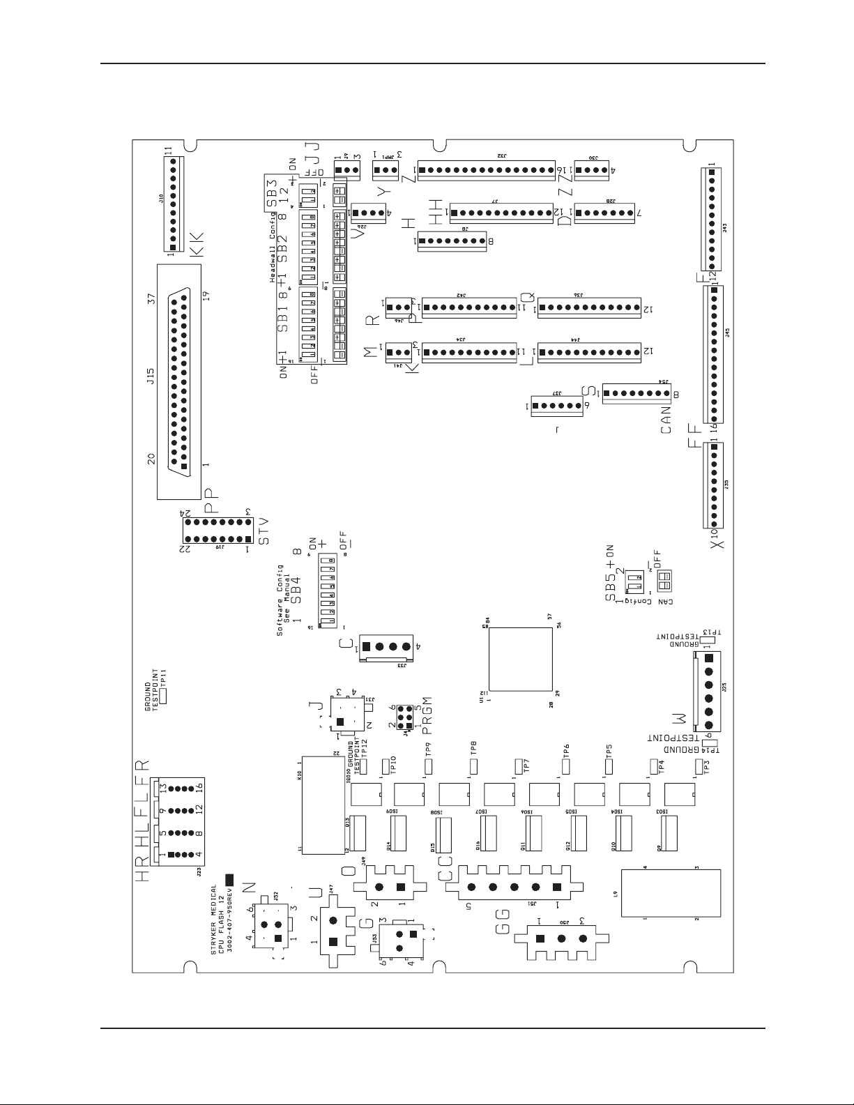
BED CIRCUIT BOARDS - CPU BOARD - 3002-407-950
Return To Table of Contents
www.stryker.com 4701-109- 002 REV C 23
Page 24

Electrical Service Information
BED CIRCUIT BOARDS - CPU BOARD - 3002-407-950 (CONTINUED)
CONNECTOR
LOCATION
J25 W +12 VDC Pin 1 Pin 4 or 5
J25 W +5 VDC Pin 2 & 3 Pin 4 or 5
J25 W -12 VDC Pin 6 Pin 4 or 5
J50 GG
J50 GG
J51 CC
J51 CC
J49 O 120 VAC Pin 1 Pin 2 Line Voltage to Bed
J52 N
J52 N
J53 G
J53 G
CABLE
LOCATION
VOLTAGE
0 VAC W/O Switch
120 VAC W/Switch
0 VAC W/O Switch
120 VAC W/Switch
0 VAC W/O Switch
120 VAC W/Switch
0 VAC W/O Switch
120 VAC W/Switch
0 VAC W/O Switch
120VAC W/Switch
0 VAC W/O Switch
120VAC W/Switch
0 VAC W/O Switch
120VAC W/Switch
0 VAC W/O Switch
120VAC W/Switch
POSITIVE
LEAD
Pin 2 Green Pin 1 White Reverse Trend
Pin 3 Black Pin 1 White Trend
Pin 1 Black Pin 3 White Fowler Up
Pin 2 Green Pin 3 White Fowler Down
Pin 3 Green Pin 1 White Bed Lift Up
Pin 6 Black Pin 1 White Bed Lift Down
Pin 3 Green Pin 1 White Skoocher Out
Pin 6 Black Pin 1 White Skoocher In
NEGATIVE
LEAD
DESCRIPTION
Relays & Siderails
Light Voltage
+5 VDC from
Power Supply
Relays & Siderails
Light Voltage
Return To Table of Contents
24 4701-109- 002 REV C www.stryker.com
Page 25
Electrical Service Information
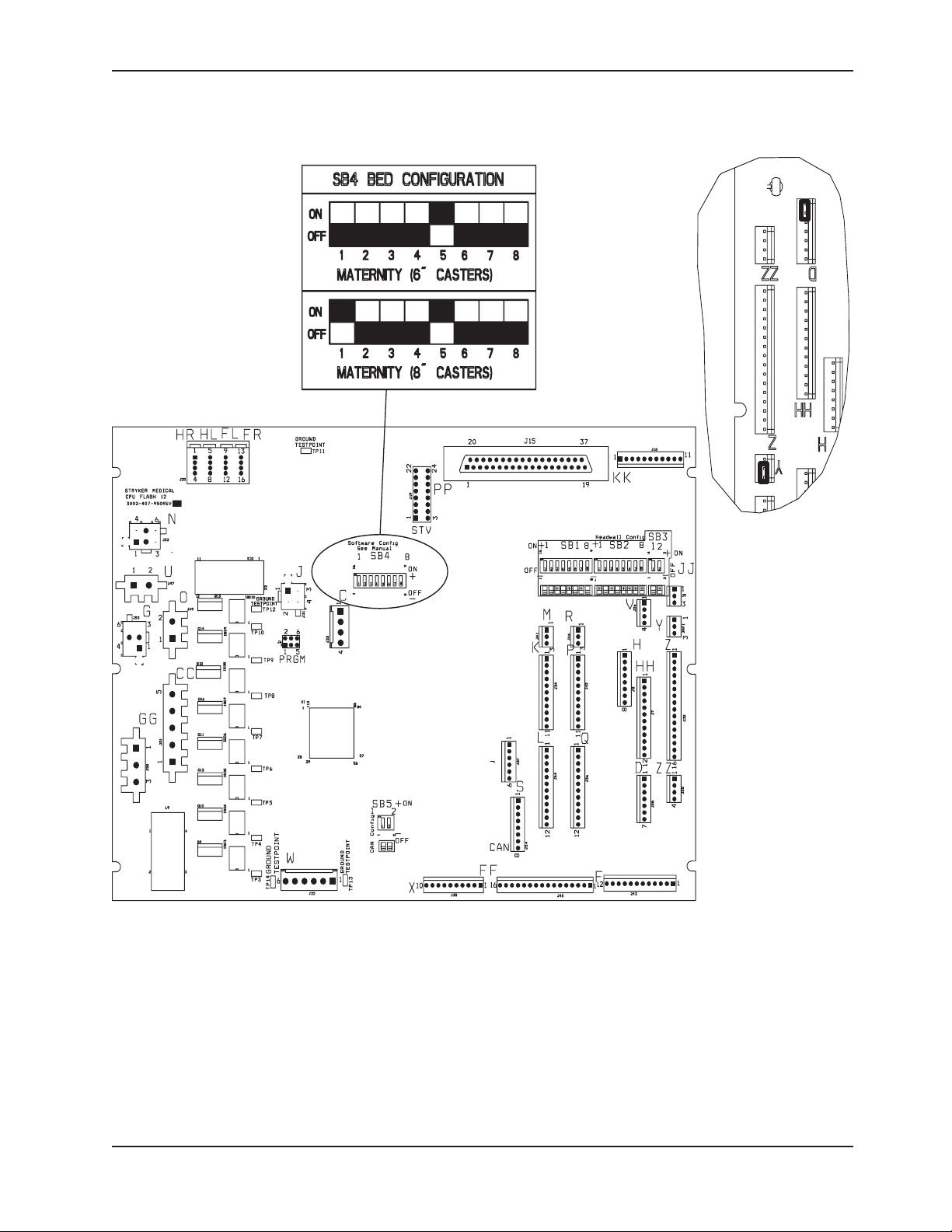
BED CIRCUIT BOARDS - SOFTWARE CONFIGURATION
Locate switch bank 4, labeled SB4 on the CPU board (see above).
1.
Move the switches to the appropriate positions as shown above.
2.
Return To Table of Contents
www.stryker.com 4701-109- 002 REV C 25
Page 26
Electrical Service Information
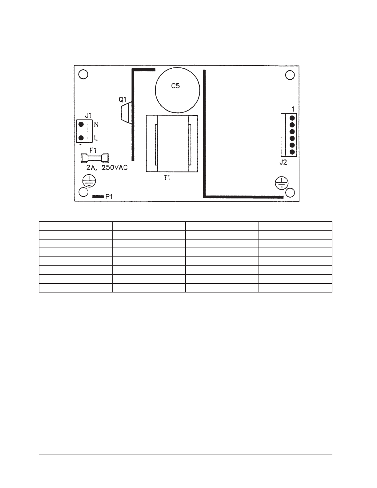
BED CIRCUIT BOARDS - POWER SUPPLY - 0059-157-000
CONNECTOR LOCATION VOLTAGE POSITIVE LEAD NEGATIVE LEAD
J1 110V Pin 1 Pin 2
J2 12V Pin 1 Pin 4 or 5
J2 5V Pin 2 Pin 4 or 5
J2 5V Pin 3 Pin 4 or 5
J2 GND Pin 4 Pin 4 or 5
J2 GND Pin 5 Pin 4 or 5
J2 -12V Pin 6 Pin 4 or 5
Return To Table of Contents
26 4701-109- 002 REV C www.stryker.com
Page 27
Electrical Service Information
J3 J2 J5
J4
J6
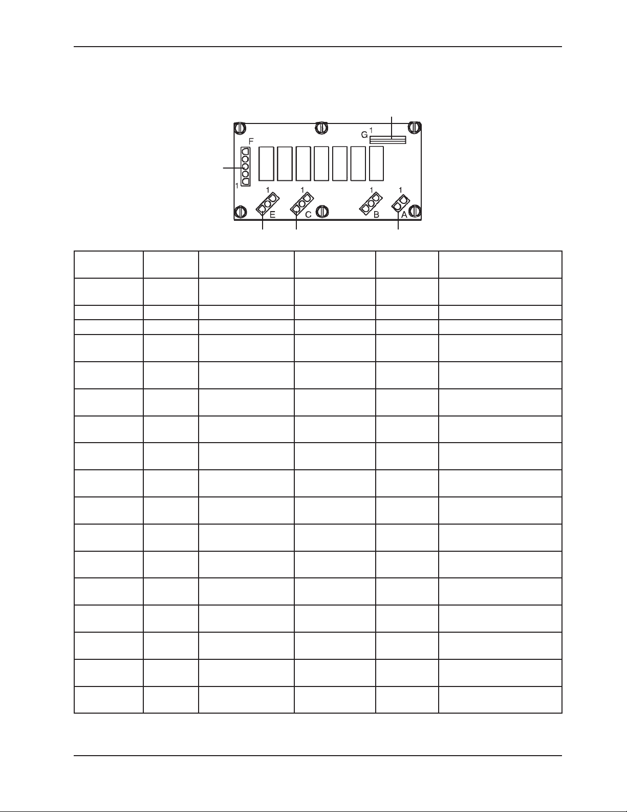
BED CIRCUIT BOARDS - FOOT POWER BOARD - 4701-080-053
CONNECTOR
LOCATION
J1 A 120 VAC* Pin 1 Pin 2 AC Line Voltage
J4 G +5 VDC Pin 2 White Pin 1 Black +5 VDC from CPU
J4 G 12 VDC Pin 3 Pin 1 Black DC Voltage from CPU
J4 G 0 VDC W/O Switch
J4 G 0 VDC W/O Switch
J4 G 0 VDC W/O Switch
J4 G 0 VDC W/O Switch
J4 G 0 VDC W/O Switch
J4 G 0 VDC W/O Switch
J3 E 0 VAC W/O Switch
J3 E 0 VAC W/O Switch
J4 E 0 VDC W/O Switch
J2 C 0 VAC W/O Switch
J2 C 0 VAC W/O Switch
J5 B 0 VAC W/O Switch
J6 F 0 VAC W/O Switch
J6 F 0 VAC W/O Switch
CABLE
LOCATION
VOLTAGE POSITIVE LEAD
Pin 5 Orange Pin 1 Black Foot Down
5 VDC W/Switch
Pin 4 Green Pin 1 Black Foot Up
5 VDC W/Switch
Pin 6 Blue Pin 1 Black Compressor
5 VDC W/Switch
Pin 7
5 VDC W/Switch
5 VDC W/Switch
5 VDC W/Switch
120 VAC W/Switch
120 VAC W/Switch
5 VDC W/Switch
120 VAC W/Switch
120 VAC W/Switch
120 VAC W/Switch
120 VAC W/Switch
120 VAC W/Switch
White/Black
Pin 8 Red/Black Pin 1 Black Lumbar Firm
Pin 9
Green/Black
Pin 2 Pin 1 Seat Soft
Pin 3 Pin 1 Seat Firm
Pin 10
Orange/Black
Pin 2 Pin 1 Lumbar Soft
Pin 3 Pin 1 Lumbar Soft
Pin 3 Black Pin 1 White Compressor
Pin 2 Red Pin 3 White Foot Down
Pin 1 Black Pin 3 White Foot Up
NEGATIVE
LEAD
Pin 1 Black Lumbar Soft
Pin 1 Black Seat Soft
Pin 1 Black Seat Firm
DESCRIPTION
from CPU Board
* 120 VAC present when Fowler slide, lumbar, or seat button is pressed.
Return To Table of Contents
www.stryker.com 4701-109- 002 REV C 27
Page 28

Electrical Service Information
OPTIONAL BED COMMUNICATIONS TESTER - 3002-045-700
Item Part No. Part Name Qty.
A 3002-045-805 BCT Unit 1
B 3001-303-825 37-Pin Cable 1
C 3002-045-806 Instructions 1
D 3000-303-087 9V Battery 1
Return To Table of Contents
28 4701-109- 002 REV C www.stryker.com
Page 29
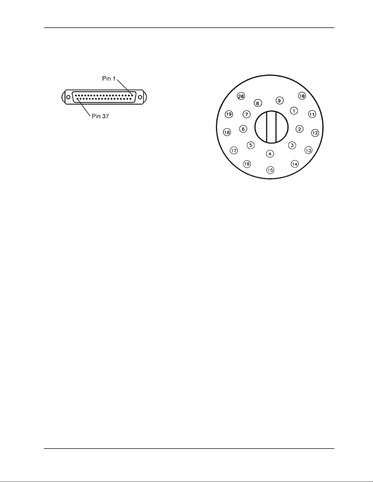
HEAD WALL OUTPUT CONFIGURATION
37−PIN CONNECTOR
STRYKER PENDANT PORT
Pin 1 Option 2 Common
Pin 2 Read Light
Pin 3 Room Light
Pin 4 Speaker High
Pin 5 Pot Wiper
Pin 6 Radio Common
Pin 7 Nurse Call Interlock
Pin 8 Audio Transfer Pin 9 Audio Transfer +
Pin 10 Interlock +
Pin 11 Interlock Pin 12 Spare
Pin 13 Options 3 Common
Pin 14 Pot Low Common
Pin 15 Pot High Common (Std.)/Audio (STV)
Pin 16 Nurse Answer Light +
Pin 17 Option 1 NO/NC
Pin 18 Option 1 Common
Pin 19 Nurse Call Light +
Pin 20 Option 2 NO/NC
Pin 21 Option 3 NO/NC
Pin 22 Option 3A NO/NC
Pin 23 Option 2A Common
Pin 24 Option 2A NO/NC
Pin 25 Nurse Call +
Pin 26 Nurse Call NO/NC
Pin 27 Room/Read Light Common
Pin 28 Nurse Call Light Pin 29 Nurse Answer Light Pin 30 Priority NO/NC
Pin 31 Priority Common
Pin 32 Option 3A Common
Pin 33 TV - (Std.)/Data (STV)
Pin 34 TV + (Std.)/Common (STV)
Pin 35 Speaker Low Common
Pin 36 Audio Shield
Pin 37 Radio NO/NC
Electrical Service Information
1 Scan Line
2 Audio (-)
3 Nurse Call (+)
4 +5 VDC
5 Scan Line
6 Scan Line
7 Nurse Call (-)
8 TV Channel Up
9 Backlight
10 Audio (+)
11 Gatch Up/Fowler In/Foot Up/DMS Firm
12 Gatch Down/Fowler Out/Foot Out/DMS Soft
13 Fowler Up/Trend In
14 Fowler Down/Trend Out
15 Audio Shield
16 Not Used - Socket Filled
17 Bed Up
18 Ground
19 Read Light/Bed Down
20 Room Light
www.stryker.com 4701-109- 002 REV C 29
Return To Table of Contents
Page 30
Service Information
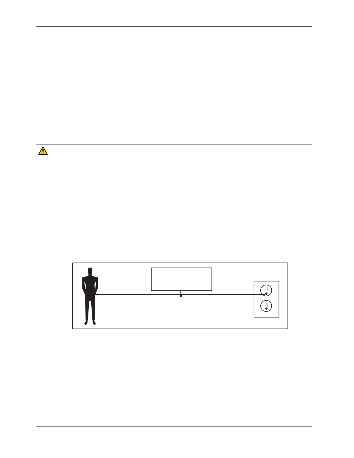
BED
GROUNDING DIAGRAM
STATIC DISCHARGE PRECAUTIONS
The electronic circuits in the bed are completely protected from static electricity damage only while the bed is
assembled. It is extremely important that all service personnel always use adequate static protection when servicing
the electronic systems of the bed. Whenever you are touching wires, you should be using static protection.
Static Protection Equipment
The necessary equipment for proper static protection is:
1 static wrist strap; 3M part number 2214 or equivalent,
•
1 grounding plug; 3M part number 61038 or equivalent,
•
1 test lead with a banana plug on one end and an alligator clip on the other; Smith part number N132B699 or
•
equivalent.
CAUTION
All electronic service parts will be shipped in static shielding bags. Do not open the bags until you have completed
steps 2 and 3 of the following procedure. Do not place unprotected circuit boards on the floor. All circuit boards to be
returned to Stryker Medical should be shipped in the static shielding bags the new boards were shipped in.
Static Protection Procedure
Unplug the power cord from the power source.
1.
Insert the grounding plug into a properly grounded hospital grade power source. Plug the banana plug of the test
2.
lead into the receptacle on the grounding plug. Connect the alligator clip on the other end of the test lead to a
ground point on the bed.
Place the static control wrist strap on your wrist. Connect the alligator clip at the other end of the wrist strap cord
3.
to a ground point on the bed.
Return To Table of Contents
30 4701-109- 002 REV C www.stryker.com
Page 31

Service Information
CPU BOARD REPLACEMENT (3002-407-950)
Tools Required:
Phillips Screwdriver
•
Needle Nose Pliers
•
Procedure:
Raise the litter and the Fowler to full up.
1.
Unplug the bed power cord from the power source. Properly ground yourself (see Static Protection Procedure)
2.
Using the Phillips screwdriver remove the three Phillips screws holding the plastic CPU board cover on the
3.
electrical pan and set the cover aside.
Unplug the electrical connectors from the CPU. Note the locations of the cables so they will be connected properly
4.
to the replacement CPU.
Lift up on the CPU board and use the needle nose pliers to unclip the five CPU board stand-off. Remove the CPU
5.
board from the stand-off.
Install the new CPU board on the stand-off and reattach all the electrical connectors. Verify proper connection by
6.
matching the letter on the cable to the letter on the CPU board.
Match the dip-switch settings on the new CPU board to the settings on the old CPU board. Reference the diagram
7.
on bed circuit board for switch settings. Transfer any shunts from the old CPU board to the new CPU board.
Discard the old CPU board. Reference the burn-in procedures sections.
Replace the CPU board cover on the electrical pan.
8.
Plug the power cord into the power source and test all the functions of the bed for proper operation before
9.
returning the bed to service.
POWER SUPPLY REPLACEMENT (0059-157-000)
Tools Required:
Phillips Screwdriver
•
Needle Nose Pliers
•
Procedure:
Raise the litter and the Fowler to full up.
1.
Unplug the bed power cord from the power source. Properly ground yourself (see Static Protection Procedure).
2.
Using the Phillips screwdriver remove the three Phillips screws holding the CPU board cover on the electrical pan
3.
and set the cover aside.
Unplug the electrical connectors from the power supply. Note the locations of the cables so they will be connected
4.
properly to the replacement power supply.
Lift up on the power supply and use the needle nose pliers to unclip the four power supply stand-off. Remove the
5.
power supply from the stand-off and discard.
Install the new power supply on the stand-off and reattach all the electrical connectors.
6.
Replace the CPU board cover on the electrical pan.
7.
Plug the power cord into the power source and test all the functions of the bed for proper operation before
8.
returning the bed to service.
Return To Table of Contents
www.stryker.com 4701-109- 002 REV C 31
Page 32

Service Information
FOOT POWER BOARD REPLACEMENT (4701-080-053)
Tools Required:
Phillips Screwdriver
•
5/8” Combination Wrench
•
Procedure:
Raise the litter and the foot section to full up.
1.
Unplug the bed power cord from the power source. Properly ground yourself (see Static Protection Procedure).
2.
Remove the foot section mattress assembly (if attached) and set aside.
3.
Remove the fluid basin and set aside.
4.
Pivot the foot pan assemblies to the side to allow access to the foot end of the bed.
5.
Using a Phillips screwdriver, remove the two screws from the bottom of the foot end litter cover.
6.
Using a 5/8” wrench, remove the two fluid basin retaining posts and remove the foot end litter cover.
7.
Unplug the cables from the foot power board. Note the locations of the cables so they will be connected properly
8.
to the replacement power board. The letters on the cables match the lettered connections on the power board.
Using a Phillips screwdriver, remove the six screws holding the foot power board to the mounting bracket. Carefully
9.
remove the foot power board from the mounting bracket.
Reverse to install the new foot power board.
10.
Plug the power cord into the power source and test the functions of the bed for proper operation before returning
11.
the bed to service.
BRAKE ADJUSTMENT
Tools Required:
3/8” Drive Ratchet
•
3/8” Drive 7/16” Socket
•
Slip Joint Pliers
•
Procedure:
Put the brake pedal in the neutral position.
1.
Remove the base cover on the side of the base with the brake needing adjustment. Pull upward firmly to separate
2.
the base cover to the base frame and remove the cover.
Using a 7/16” socket, loosen the brake ring pivot bolt.
3.
Using slip joint pliers, if needed turn the brake adjuster until there is approximately a 3/8” gap between the top
4.
of the caster and the bottom of the brake ring. Holding the brake adjuster in that position, use a 7/16” socket to
tighten the brake ring pivot bolt.
Verify the brakes are holding and releasing properly.
5.
Reinstall the base hood.
6.
Again, verify the brakes are holding and releasing properly before returning the bed to service.
7.
Return To Table of Contents
32 4701-109- 002 REV C www.stryker.com
Page 33

Service Information
BED LIFT MOTOR REPLACEMENT (120V - 4701-700-005)
Tools Required:
3/8” Drive Ratchet
•
3/8” Drive and 7/16” Socket
•
T27 Torx driver driver
•
Bungee Cord
•
Diagonal Pliers
•
Phillips Screwdriver
•
Procedure:
Raise the litter, the Fowler and the siderails to the full upright position.
1.
Unplug the bed power cord from the power source.
2.
Using a Phillips screwdriver remove the three Phillips screws holding the plastic CPU board cover on the electrical
3.
pan and set the cover aside.
Using a Phillips screwdriver remove the three Phillips screws holding the front of the electrical pan to the litter.
4.
Using a T27 torx driver, remove the two T27 Torx screws at the head end of the bed below the power cord holding
5.
the electrical panel to the litter.
Push forward and lift the electrical pan up toward the foot of the bed and, using a bungee cord, support it from
6.
the siderail timing links.
CAUTION
Before removing the last motor mounting bolt, hold the bed lift motor so that it will not fall and cause damage.
7. Using diagonal pliers, cut the two cable ties holding the cables to the mounting bracket.
Unplug the bed lift motor quick connection.
8.
Using a 3/8” ratchet and 7/16” socket, remove the two 7/16” bolts holding the motor mounting bracket to the motor
9.
mount.
Move the motor toward the head of the bed and lift it up and out.
10.
Reverse the procedure to install the new motor. Verify proper function before returning the bed to service.
11.
Return To Table of Contents
www.stryker.com 4701-109- 002 REV C 33
Page 34

Service Information
TRENDELENBURG MOTOR REPLACEMENT (120V - 4701-032-095)
Tools Required:
3/8” Drive Ratchet
•
3/8” Drive and 7/16” Deep Well Socket
•
5/16” Nut Driver
•
3/8” Drive T27 Torx
•
Bungee Cord
•
Needle Nose Pliers
•
Phillips Screwdriver
•
Inclinometer
•
Procedure:
Raise the litter, the Fowler and the siderails to the full upright position.
1.
Unplug the bed power cord from the power source.
2.
Using a Phillips screwdriver, remove the three Phillips screws holding the plastic CPU board cover on the electrical
3.
pan and set the cover aside.
Unplug the Trendelenburg motor electrical connector (N) from the CPU board and cut the cable tie.
4.
Using a 3/8” ratchet with a 7/16” deep well socket, remove the ground lug nut and the trend motor ground wire.
5.
Using a Phillips screwdriver, remove the three Phillips screws holding the front of the electrical pan to the litter.
6.
Using a T27 Torx driver , remove the two T27 Torx screws at the head end of the bed below the power cord hold-
7.
ing the electrical panel to the litter.
Lift the electrical pan up toward the foot end of the bed and, using a bungee cord, support it from the siderail
8.
timing links.
Unplug the two capacitor wires for the Trendelenburg motor.
9.
Using a 5/16” nut driver, remove the two 5/16” screws from the limit switch bracket and lay the bracket over the
10.
side of the bed.
WARNING
Once the rue clip and clevis pin are removed from the motor drive tube, the bed will lean toward the food end. A hard
stop will prevent excessive tipping. Use caution when removing the rue clip and clevis pin to avoid possible injury or
damage to the bed.
Note
It is necessary to apply downward or upward pressure on the head end litter top to remove the clevis pin.
Using needle nose pliers, remove the rue clip and the clevis pin from the trend motor drive tube.
11.
Using a T27 Torx driver, remove the four T27 screws holding the Trend motor to the litter.
12.
Lift the motor up and out.
13.
To reinstall the new motor follow the steps on the following page.
14.
Return To Table of Contents
34 4701-109- 002 REV C www.stryker.com
Page 35

Service Information
TRENDELENBURG MOTOR REPLACEMENT (CONTINUED)
To reinstall the Trend motor:
Position the new trend motor at the head end of the litter and secure through the mounting plate with the four T27
1.
screws.
Rotate the drive tube on the motor shaft towards the motor housing until there is a 1/4” gap between the end of
2.
the drive tube and the motor housing.
Slide the clevis pin through the drive tube and the Trend weldment to attach the drive tube. (It may be necessary
3.
to press down on the head end of the bed to align the drive tube with the Trend weldment). Install the rue-clip to
secure the assembly.
Plug the motor cable into the proper connector (N) on the CPU board and attach the motor capacitor
4.
connections.
Plug the bed power cord into the power source.
5.
CAUTION
Keep your fingers clear of moving parts when activating the Trend motor to avoid possible injury.
Place an inclinometer directly on the seat surface and press the “Trend” button until approximately 1° of Trend is
6.
attained.
Reinstall the Trend switch bracket. With the fasteners in place, slide the bracket until the “Trend Zero” switch is on
7.
the verge of activation against the end of the drive tube (you will hear a soft click).
Press and hold the Trend button until the bed begins to move into a Trend position. Then press and hold level
8.
button and verify 1o of trend is where it stops.
Plug in the two capacitor wires for the Trendelenburg motor.
9.
Remove bungee cord securing electrical pan up.
10.
Using a T27 Torx driver, secure the two T27 Torx screws at the head end of the bed below the power cord holding
11.
the electrical panel to the litter.
Using a Phillips screwdriver, secure the three Phillips screws holding the front of the electrical pan to the litter.
12.
Using a 3/8” ratchet with a 7/16” deep well socket, secure the ground lug nut and the trend motor ground wire.
13.
Plug the Trendelenburg motor electrical connector (N) from the CPU board and secure with a new cable tie.
14.
Using a Phillips screwdriver, secure the three Phillips screws holding the plastic CPU board cover on the electrical
15.
pan.
Verify proper function before returning to service.
16.
Return To Table of Contents
www.stryker.com 4701-109- 002 REV C 35
Page 36

Service Information
FOWLER MOTOR REPLACEMENT (120V - 4701-035-040)
Tools Required:
3/8” Ratchet
•
3/8” Drive 7/16” Socket
•
Bungee Cord
•
3/8” Drive T27 Torx
•
Regular Screwdriver
•
7/16 Combination Wrench
•
Phillips Screwdriver
•
Procedure:
Raise the litter, the Fowler (using the manual CPR release handle) and the siderails to the full upright position.
1.
Using a Phillips screwdriver, remove the three Phillips screws holding the plastic CPU board cover on the electrical
2.
pan and set the cover aside.
Lift the bellows cover up toward the Fowler and, using a bungee cord, support it from the siderail timing links.
3.
Insert a #2 Phillips screwdriver in the side of the Fowler support bracket on either side of the bed. Pull the CPR
4.
handle to put pressure on the screwdriver and provide support for the Fowler.
If the bed has the Skoocher™ option, use the siderail button to move it all the way in toward the foot end of the
5.
bed.
Unplug the bed power cord from the power source.
6.
Carefully pull up the corners of the motor cover to remove the four plastic push rivets. (Use a regular screwdriver
7.
to remove the push rivets, if necessary.) Set aside the motor cover.
Unplug the electrical quick connector near the motor.
8.
If the bed has the Skoocher™ option, use a 7/16” socket to remove the two bolts holding the fowler motor mounting
9.
bracket to the litter frame. If the bed does not have the Skoocher option, use a 7/16” wrench. Hold the fowler motor
before removing the last bolt.
While allowing the motor to hang, compress the white CPR coupler components together and remove the CPR
10.
coupler assembly.
Lift up on the fowler motor, angle it over the motor frame support and remove from the patients right side.
11.
Reverse the procedure to install the new motor. Verify proper function before returning the bed to service.
12.
Return To Table of Contents
36 4701-109- 002 REV C www.stryker.com
Page 37

Service Information
FOWLER BALL SCREW REPLACEMENT (4701-035-012)
Tools Required:
3/8” Ratchet
•
3/8” Drive 7/16” Socket
•
Large Retaining Ring Pliers
•
3/8” Drive T27 Torx
•
Standard Screwdriver
•
Bungee Cord
•
Needle Nose Pliers
•
Phillips Screwdriver
•
5/8” Combination Wrench
•
Procedure:
Raise the litter, the Fowler and the siderails to the full upright position.
1.
Using a Phillips screwdriver, remove the three Phillips screws holding the plastic CPU board cover on the electrical
2.
pan and set the cover aside.
Remove the foot section mattress assembly (if attached) and set it aside.
3.
Remove the fluid basin and set aside.
4.
Remove the head end mattress.
5.
Using a T27 Torx, remove the four screws holding the seat section to the litter frame.
6.
Using a Phillips screwdriver, remove the two Phillips screws from the foot litter cover.
7.
Using a 5/8” combination wrench remove the two fluid basin buttons, then remove the cover and set aside.
8.
Using a 3/8” ratchet and 7/16” socket, remove the ground strap from the seat section which is attached to the foot
9.
motor support bracket.
Remove the seat section.
10.
Lift the bellows cover up toward the Fowler and, using a bungee cord, support it from the siderail timing links.
11.
Insert a #2 Phillips screwdriver in the side of the Fowler support bracket on either side of the bed. Pull the CPR
12.
handle to put pressure on the screwdriver and provide support for the Fowler.
Unplug the bed power cord from the power source.
13.
Carefully pull up the corners of the motor cover to remove the four plastic push rivets. (Use a standard screwdriver
14.
to remove the push rivets, if necessary.) Set aside the motor cover.
Using a 7/16” socket, remove the bolt and bushings holding the steel potentiometer cable to the ball screw nut
15.
box.
Using a 7/16” socket, remove the bolt and bushing on the opposite side.
16.
Using needle nose pliers, remove the cotter and clevis pins from the head end of the ball screw and slide the ball
17.
screw assembly out toward the foot end.
Using large retaining ring pliers, remove the retaining ring holding the ball screw nut to the nut box and remove
18.
the nut box.
Using a 7/16” socket, remove the bolt from the hard stop collar at the end of the ball screw.
19.
Reverse the procedure to install the new ball screw. Verify proper function before returning the bed to service.
20.
Note
When reinstalling the cotter pin, be sure to fully bend it around the clevis pin to prevent it from contacting Fowler
components during operation.
Return To Table of Contents
www.stryker.com 4701-109- 002 REV C 37
Page 38

Service Information
SKOOCHER™ MOTOR REPLACEMENT
Tools Required:
3/8” Ratchet
•
3/8” Drive 7/16” Socket
•
Bungee Cord
•
3/8” Drive T27 Torx
•
Standard Screwdriver
•
Diagonal Pliers
•
Phillips Screwdriver
•
Procedure:
Raise the litter, the Fowler (using the manual CPR release handle) and the siderails to the full upright position.
1.
Remove the three Phillips screws holding the plastic CPU board cover on the electrical pan and set the cover
2.
aside.
Lift the bellows cover up toward the Fowler and, using a bungee cord, support it from the siderail timing links.
3.
Insert a #2 Phillips screwdriver in the side of the Fowler support bracket on either side of the bed. Pull the CPR
4.
handle to put pressure on the screwdriver and provide support for the Fowler.
Use the siderail button to move the Skoocher™ all the way toward the foot end of the bed if the motor will run.
5.
Unplug the bed power cord from the power source.
6.
Carefully pull up the corners of the motor cover to remove the four plastic push rivets. (Use a standard screwdriver
7.
to remove the push rivets, if necessary.) Set aside the motor cover.
Unplug the electrical quick connector near the Skoocher™ motor.
8.
Use a 7/16” socket to remove the two bolts holding the fowler motor mounting bracket to the litter frame. Hold the
9.
motor before removing the last bolt.
Using a standard screwdriver, compress the white CPR coupler components together and lift the motor out of the
10.
top of the assembly.
Using diagonal pliers, cut the cable tie holding the capacitor and wires to the motor.
11.
Using a 7/16” socket, remove the four bolts holding the motor mounting bracket to the motor.
12.
Reverse the procedure to install the new motor. Verify proper function before returning the bed to service.
13.
Return To Table of Contents
38 4701-109- 002 REV C www.stryker.com
Page 39

Service Information
FOOT MOTOR REPLACEMENT (120V - 4701-040-035 / 230V - 4712-040-035)
Tools Required:
3/8” Ratchet
•
3/8” Drive 7/16” Socket
•
Crescent Wrench
•
3/8” Drive T27 Torx
•
5/8” Combination Wrench
•
5/32” Allen Wrench
•
Diagonal Pliers
•
Phillips Screwdriver
•
3/8” Allen Wrench
•
Procedure:
Raise the litter to full up and lower the foot section to full down.
1.
Note
If it’s necessary to manually lower the foot motor, remove the plastic foot end litter cover (see below) and use a
crescent wrench to manually turn the manual backup nut at the end of the motor shaft.
Remove the head section mattress.
2.
Remove the foot section assembly (if attached) and set it aside.
3.
Pivot the foot pan assemblies to the side to allow access to the foot end of the bed.
4.
Using a Phillips screwdriver, remove the two screws from the bottom of the plastic foot end litter cover.
5.
Using a 5/8” wrench, remove the two steel fluid basin retaining posts from the front of the cover and remove the
6.
plastic foot end litter cover.
Using a T27 Torx, remove the four screws holding the seat section to the litter frame and remove the seat
7.
section.
Cut the cable tie holding the capacitor to the litter frame and the two cable ties holding the motor power cable to
8.
the optional power board mounting bracket.
Unplug the foot lift motor from the foot power board (connector F).
9.
Using a 7/16” socket, remove the four bolts holding the foot motor to the cross brace.
10.
Using a crescent wrench, turn the bottom of the motor shaft and lower the foot motor almost completely.
11.
Slide the motor toward the patient, left side of the bed. Lift and tip the motor toward the foot end of the bed to
12.
remove it from the litter.
Using a 5/32” Allen wrench, remove the Allen screw holding the bottom hard stop collar on the motor shaft. Save
13.
the collar to use on the new motor.
Using a 3/8” Allen wrench, remove the two Allen screws holding the upper motor hard stop on the motor shaft.
14.
Save the hard stop to use on the new motor.
Reverse the procedure to install the new motor. Verify proper function before returning the bed to service.
15.
Return To Table of Contents
www.stryker.com 4701-109- 002 REV C 39
Page 40

Service Information
OPTIONAL AIR MATTRESS COMPRESSOR REPLACEMENT (120V - 4701-048-015 / 230V - 4712-048-015)
Tools Required:
3/8” Ratchet
•
3/8” Drive 7/16” Socket
•
Crescent Wrench
•
5/16” Combination Wrench
•
3/8” Drive T27 Torx
•
5/8” Combination Wrench
•
5/32” Allen Wrench
•
3/32” Allen Wrench
•
Diagonal Pliers
•
Phillips Screwdriver
•
3/8” Allen Wrench
•
Procedure:
Raise the litter to full up and lower the foot section to full down.
1.
Note
If it’s necessary to manually lower the foot motor, remove the plastic foot end litter cover (see below) and use a
crescent wrench to manually turn the manual backup nut at the end of the motor shaft.
Remove the head section mattress and set it aside.
2.
Remove the foot section assembly (if attached) and set it aside.
3.
Pivot the foot pan assemblies to the side to allow access to the foot end of the bed.
4.
Using a Phillips screwdriver, remove the two screws from the bottom of the plastic foot end litter cover.
5.
Using a 5/8” wrench, remove the two steel fluid basin retaining posts from the front of the cover and remove the
6.
plastic foot end litter cover.
Using a T27 Torx, remove the four screws holding the seat section to the litter frame and remove the seat
7.
section.
Cut the cable tie holding the capacitor to the litter frame and the two cable ties holding the motor power cable to
8.
the optional power board mounting bracket.
Unplug the foot lift motor from the foot power board (connector F).
9.
Using a 7/16” socket, remove the four bolts holding the foot motor to the cross brace.
10.
Using a crescent wrench, turn the bottom of the motor shaft and lower the foot motor almost completely.
11.
Slide the motor toward the patient, left side of the bed. Lift and tip the motor toward the foot end of the bed to
12.
remove it from the litter.
Disconnect the air tubes from the quick-release connectors on the outside of the litter. Pull the hoses out of the
13.
channels on the foot end of the litter.
Using a Phillips screwdriver, remove the three screws holding the mounting bracket assembly to the litter and
14.
carefully remove the assembly.
Unplug the compressor cable from the foot power board (connector B).
15.
Using a 3/32” Allen wrench, remove the four screws holding the pump to the mounting bracket.
16.
Reverse the procedure to install the new compressor. Verify proper function before returning the bed to service.
17.
Return To Table of Contents
40 4701-109- 002 REV C www.stryker.com
Page 41

Service Information
NIGHT LIGHT REPLACEMENT (4701-080-080)
Tools Required:
Phillips Screwdriver
•
Procedure:
Raise the litter to full up.
1.
Remove the foot section assembly (if attached) and set it aside.
2.
Using a Phillips screwdriver, remove the screw holding the night light assembly to the litter.
3.
Carefully unplug the two wire connections for the night light and discard the old night light.
4.
Reverse the procedure to install the new night light. Verify proper function before returning the bed to service.
5.
NURSE CALL 9V BATTERY REPLACEMENT
If the Power LED (located on the outside of both siderails) is flashing, the 9V Nurse Call battery at the head end of
the bed needs to be replaced. No tools are required to replace the battery. Unplug the bed power cord from the power
source and replace the battery. After replacing the battery, verify the Power LED is no longer flashing and operates
normally when the different light settings are selected. Properly dispose of the old battery in accordance with local
regulations.
DIAGNOSTICS MODE
To enter the diagnostics mode:
1.
Press and hold the Trend and Reverse Trend/Level buttons.
a.
While holding the Trend and Reverse Trend/Level buttons, plug the bed power cord back into the power
b.
source.
Release the buttons. The Bed Up LED and the Bed Motion Lock LED on the siderail will flash to indicate the
c.
bed is in diagnostic mode.
Unplug the bed power cord from the power source to exit the diagnostics mode.
2.
Return To Table of Contents
www.stryker.com 4701-109- 002 REV C 41
Page 42

Service Information
FOOT POTENTIOMETER REPLACEMENT
Tools Required:
3/8” Ratchet
•
3/8” Drive 7/16” Socket
•
Phillips Screwdriver
•
5/8” Combination Wrench
•
5/16” Nut Driver
•
Diagonal Pliers
•
Procedure:
Raise the litter to full up and lower the foot section to full down.
1.
Remove the foot section assembly (if attached) and set it aside.
2.
Pivot the foot pan assemblies to the side to allow access to the foot end of the bed.
3.
Using a Phillips screwdriver, remove the two screws from the bottom of the plastic foot end litter cover.
4.
Using a 5/8” wrench, remove the two steel fluid basin retaining posts from the front of the cover and remove the
5.
plastic foot end litter cover.
Unplug the potentiometer electrical quick connect.
6.
Cut the cable tie at the top of the seat section near the bolt securing the potentiometer.
7.
Using a 7/16” socket, remove the bolt securing the potentiometer steel cable to the foot lift casting. Carefully
8.
remove the bolt and washer and slowly retract the potentiometer cable.
Using a 7/16” socket, while holding the potentiometer with one hand, remove the bolt holding the potentiometer to
9.
the seat section litter brace.
Reverse the procedure to install the new potentiometer. Perform the potentiometer burn-in procedure on the Foot
10.
Potentiometer Burn-in Procedure section. Verify proper function before returning the bed to service.
Return To Table of Contents
42 4701-109- 002 REV C www.stryker.com
Page 43

Service Information
FOOT POTENTIOMETER BURN-IN PROCEDURE
Procedure:
Unplug the bed power cord from the power source.
1.
Enter the diagnostics mode:
2.
Press and hold the Trend and Reverse Trend/Level buttons.
a.
While holding the Trend and Reverse Trend/Level buttons, plug the bed power cord back into the power
b.
source.
Release the buttons. The Bed Up LED and the Bed Motion Lock LED on the siderail will flash to indicate the
c.
bed is in diagnostic mode.
Press the Bed Up button and raise the litter far enough to prevent damage when the foot is fully lowered
3.
(approximately 25 inches from the floor to the seat top surface).
Press and hold the Foot Down button until the foot casting hits the full down and then run the foot lift 3/8” from
4.
the bottom hard stop.
CAUTION
Release the Foot Down button immediately if the foot support touches the litter frame or damage could occur.
Press and hold the Trend button and then press the Foot Down button, in that order. The Bed Motion Lock LED will
5.
light and then flash on and off to indicate calibration.
Press and hold the Foot Up button until the foot casting hits the full up and then run the foot lift down 3/8” from
6.
the upper hard stop.
CAUTION
Release the Foot Up button immediately if the foot support touches the litter frame or damage could occur.
Press the Trend button and then press the Foot Up button, in that order. The Bed Motion Lock LED will light and
7.
then flash on and off to indicate calibration.
Unplug the bed power cord from the power source to exit the diagnostics mode.
8.
Return To Table of Contents
www.stryker.com 4701-109- 002 REV C 43
Page 44

Service Information
FOWLER POTENTIOMETER REPLACEMENT (4701-080-025)
Tools Required:
3/8” Ratchet
•
3/8” Drive 7/16” Socket
•
Phillips Screwdriver
•
Standard Screwdriver
•
Bungee Cord
•
3/8” Drive T27 Torx
•
Procedure:
Raise the litter, the Fowler and the siderails to the full upright position.
1.
Remove the three Phillips screws holding the CPU board cover on the electrical pan and set the cover aside.
2.
Remove the foot section assembly (if attached) and set it aside.
3.
Remove the head end mattress.
4.
Using a T27 Torx, remove the four screws holding the seat section to the litter frame and remove the seat
5.
section.
Lift the bellows cover up toward the Fowler and, using a bungee cord, support it from the siderail timing links.
6.
Insert a #2 Phillips screwdriver in the side of the Fowler support bracket on either side of the bed. Pull the CPR
7.
handle to put pressure on the screwdriver and provide support for the Fowler.
Unplug the bed power cord from the power source.
8.
Carefully pull up the corners of the motor cover to remove the four plastic push rivets. (Use a standard screwdriver
9.
to remove the push rivets, if necessary.) Set aside the motor cover.
Using a 7/16” socket, remove the bolt holding the steel potentiometer cable to the Fowler guide weldment. Do not
10.
drop the bushings.
Using a 7/16” socket, remove the bolt holding the potentiometer assembly to the frame.
11.
Using a Phillips screwdriver, remove the two screws holding the head end of the large plastic underbody cover
12.
to the litter. (The head end of the cover is supported by the litter.) Remove the two screws at the foot end of the
cover and carefully remove the cover.
Cut the cable tie holding the potentiometer cable.
13.
Unplug the cable and remove the potentiometer.
14.
Reverse the procedure to install the new potentiometer. Perform the potentiometer burn-in procedure above.
15.
Verify proper function before returning the bed to service.
FOWLER POTENTIOMETER BURN-IN PROCEDURE
Unplug the bed power cord from the power source.
1.
Enter the diagnostics mode:
2.
Press and hold the Trend and Reverse Trend/Level buttons.
a.
While holding the Trend and Reverse Trend/Level buttons, plug the bed power cord back into the power
b.
source.
Release the buttons. The Bed Up LED and the Bed Motion Lock LED on the siderail will flash to indicate the
c.
bed is in diagnostic mode.
Use the Reverse Trend/Level button to level the litter surface.
3.
Press the Fowler Down button until the top edge of the Fowler is approximately 1" from the plastic CPU board
4.
cover.
Press and hold the Trend button and then press the Fowler Down button, in that order. The Bed Up LED will light
5.
and then flash on and off to indicate calibration.
Unplug the bed power cord from the power source to exit the diagnostics mode.
6.
Return To Table of Contents
44 4701-109- 002 REV C www.stryker.com
Page 45

Service Information
LIFT POTENTIOMETER REPLACEMENT (4701-080-025)
Tools Required:
3/8” Drive Ratchet
•
Diagonal Pliers
•
Phillips Screwdriver
•
3/8” Drive T27 Torx
•
Bungee Cord
•
Procedure:
Raise the litter, the Fowler and the siderails to the full upright position.
1.
Remove the three Phillips screws holding the plastic CPU board cover on the electrical pan and set the cover
2.
aside.
Lift the bellows cover up toward the Fowler and, using a bungee cord, support it from the siderail timing links.
3.
Unplug the bed power cord from the power source.
4.
Carefully remove the potentiometer cable from the tab on the lift tube weldment and slowly retract the cable back
5.
to the potentiometer.
Using diagonal pliers, cut the cable tie holding the potentiometer cable to the electrical panel.
6.
Unplug the potentiometer.
7.
Using a T27 Torx, remove the screw holding the potentiometer to the litter frame and remove the potentiometer.
8.
Reverse the procedure to install the new potentiometer. Perform the lift potentiometer burn-in procedure (see
9.
procedure below). Verify proper function before returning the bed to service.
LIFT POTENTIOMETER BURN-IN PROCEDURE
Unplug the bed power cord from the power source.
1.
Enter the diagnostics mode:
2.
Press and hold the Trend Level buttons.
a.
While holding the Trend and Reverse Trend/Level buttons, plug the bed power cord back into the power
b.
source.
Release the buttons. The Bed Up LED and the Bed Motion Lock LED on the siderail will blink to indicate the
c.
bed is in diagnostic mode.
Press the Foot Up button and raise the foot section far enough to prevent damage when the litter is fully
3.
lowered.
Use the Reverse Trend/Level button to level the litter surface.
4.
Press the Bed Down button and lower the litter until the distance from the floor to the seat section surface
5.
measures 17.5 (+0.5/-0.0) inches for a bed with 6” casters or 19.5 (+0.5/-0.0) inches for a bed with 8" casters.
Press the Trend button and then press the Bed Down button, in that order. The Bed Motion Lock LED will light and
6.
then flash on and off to indicate calibration.
Press the Bed Up button and raise the litter until the distance from the floor to the seat section surface measures
7.
35.5 (+0.0/-0.5) for a bed with 6" casters or 37.5 (+0.0/-0.5) for a bed with 8" casters.
Press the Trend button and then press the Bed Up button, in that order. The Bed Motion Lock LED will light and
8.
then flash on and off to indicate calibration.
Unplug the bed power cord from the power source to exit diagnostics.
9.
Return To Table of Contents
www.stryker.com 4701-109- 002 REV C 45
Page 46

Service Information
SMART TV INTERFACE BURN-IN PROCEDURE
Note
Your LD304 must have the hardware for this option installed prior to completing the burn-in procedure.
Unplug the bed power cord from the power source.
1.
Enter the diagnostics mode:
2.
Press and hold the Trend and Reverse Trend/Level buttons.
a.
While holding the Trend and Reverse Trend/Level buttons, plug the bed power cord back into the power
b.
source.
Release the buttons. The Bed Up LED and the Bed Motion Lock LED on the siderail will blink to indicate the
c.
bed is in diagnostic mode.
Notice the Nurse Call LED (yellow) on the inside panel of each siderail is flashing. This represents one of the
3.
10 TV selections shown in the table below. Notice the Nurse Answer LED (green) on the inside of each siderail is
flashing on/off at a slow rate.
Press and release the “TV On/Off” button on the bed’s siderail. Notice the Nurse Call LED (yellow) flashes once
4.
with each press. This flash code is defined in the table below. Notice the Nurse Answer LED (green) is flashing
on/off at a slow rate. The Nurse Answer LED (green) will only illuminate when the Nurse Call LED (yellow) is
flashing.
Press and release the “TV On/Off” button on the bed’s siderail to increment to other TV modes. Notice the Nurse
5.
Call LED (yellow) flashes consecutively the number listed in the table below. This number represents the TV mode
selected.
When the desired TV manufacturer has been selected, unplug the bed power cord from the power source and plug
6.
it back in to complete the Smart TV burn-in procedure.
TV MANUFACTURER SELECTION FOR SMART TV BURN-IN PROCEDURE
Press and release TV ON/OFF switch Nurse Call LED (Yellow) TV Manufacturer
One time One flash RCA 1
Two times Two flashes RCA 2
Three times Three flashes Zenith 1
Four times Four flashes Zenith 2
Five times Five flashes Philips/Magnavox
Six times Six flashes Magnavox (models 9120, 9220, 9320)
Seven times Seven flashes Traditional TV
Eight times Eight flashes Traditional Plus
Nine times Nine flashes Auto Detect: Smart TV
Ten times Ten flashes Auto Detect W/Digital Volume Smart TV
Return To Table of Contents
46 4701-109- 002 REV C www.stryker.com
Page 47

For Reference Only: 4701-101-070
6” Caster/Base Assembly
Item Part No. Part Name Qty.
A 0005-042-000 Step Bolt 4
B 0016-035-000 Nylock Hex Nut 4
C 0025-103-000 Pop Rivet 2
D 0715-001-156 Ground Chain 2
E 3001-200-050 6” Steer Caster Assembly 1
F 3001-200-060 6” Caster Assembly 3
G 4701-001-095 6” Caster Cover, Right 4
H 4701-001-096 6” Caster Cover, Left 4
J 4701-001-094 Tabbed Washer 4
K 4701-101-000 Base Assembly 1
Return To Table of Contents
www.stryker.com 4701-109- 002 REV C 47
Page 48

For Reference Only: 4701-101-075
8” Caster/Base Assembly
Item Part No. Part Name Qty.
A 0005-042-000 Step Bolt 4
B 0016-035-000 Nylock Hex Nut 4
C 0025-103-000 Pop Rivet 2
D 0715-001-156 Ground Chain 2
E 3001-200-080 8” Steer Caster Assembly 1
F 3001-200-090 8” Caster Assembly 3
G 4701-001-077 8” Caster Cover, Right 4
H 4701-001-076 8” Caster Cover, Left 4
J 4701-001-094 Tabbed Washer 4
K 4701-101-000 Base Assembly 1
Return To Table of Contents
48 4701-109- 002 REV C www.stryker.com
Page 49

6” Caster Assembly - 3001-200-060
Item Part No. Part Name Qty.
A 5000-002-010 Wheel Assembly 1
B 0016-060-000 Lock Nut 1
C 0003-342-000 Hex Hd. Cap Screw 1
D 3001-200-061 Caster Horn W/Bearing 1
Return To Table of Contents
www.stryker.com 4701-109- 002 REV C 49
Page 50

6” Steer Caster Assembly - 3001-200-050
Item Part No. Part Name Qty.
A 5000-002-010 Wheel Assembly 1
B 0016-060-000 Lock Nut 1
C 0003-342-000 Hex Hd. Cap Screw 1
D 3001-200-051 Steer Caster Horn W/Bearing 1
Return To Table of Contents
50 4701-109- 002 REV C www.stryker.com
Page 51

6” Molded Wheel Assembly - 5000-002-010
Item Part No. Part Name Qty.
A 0081-226-000 Bearing 2
B 0715-001-255 Wheel Bushing 2
C 5000-002-020 Molded Wheel 1
D 6060-002-046 Bearing Spacer 1
Return To Table of Contents
www.stryker.com 4701-109- 002 REV C 51
Page 52

Optional 8” Caster Assembly - 3001-200-090
Item Part No. Part Name Qty.
A 0715-002-025 Wheel Assembly 1
B 0016-060-000 Hex Nut 1
C 0003-099-000 Hex Hd. Cap Screw 1
D 3001-200-076 Caster Horn 1
Return To Table of Contents
52 4701-109- 002 REV C www.stryker.com
Page 53

Optional 8” Steer Caster Assembly - 3001-200-080
Item Part No. Part Name Qty.
A 0715-002-025 Wheel Assembly 1
B 0016-060-000 Hex Nut 1
C 0003-099-000 Hex Hd. Cap Screw 1
D 3001-200-081 Caster Horn 1
Return To Table of Contents
www.stryker.com 4701-109- 002 REV C 53
Page 54

Optional 8” Wheel Assembly - 0715-002-025
C
B
A
D
C
D
Item Part No. Part Name Qty.
A 0715-002-124 Wheel 1
B 0052-503-000 Bearing Spacer 1
C 0081-226-000 Bearing 2
D 0715-001-255 Wheel Bearing 2
Return To Table of Contents
54 4701-109- 002 REV C www.stryker.com
Page 55

For Reference Only: 4701-101-000
Base Assembly
See Detail B
See Detail A
RIGHT SIDE
DETAIL A
www.stryker.com 4701-109- 002 REV C 55
DETAIL B
Return To Table of Contents
Page 56

Base Assembly
See Detail C
DETAIL C
See Detail D
LEFT SIDE
DETAIL D
Return To Table of Contents
56 4701-109- 002 REV C www.stryker.com
Page 57

Base Assembly
STEER LOCK
Return To Table of Contents
www.stryker.com 4701-109- 002 REV C 57
Page 58

Base Assembly
OPPOSITE SIDE
Return To Table of Contents
58 4701-109- 002 REV C www.stryker.com
PATIENT RIGHT
Page 59

Base Assembly
Item Part No. Part Name Qty.
A 0003-056-000 Hex Hd. Cap Screw 9
B 0003-139-000 Hex Hd. Cap Screw 3
C 0003-076-000 Hex Hd. Cap Screw 1
D 0003-078-000 Hex Hd. Cap Screw 2
E 0003-214-000 Hex Hd. Cap Screw 3
F 0011-053-000 Washer 1
G 0011-063-000 Washer 2
H 0014-007-000 Washer 2
J 0016-028-000 Hex Nut 2
K 0026-067-000 Slotted Spring Pin 2
L 0038-524-000 Extension Spring 1
M 0052-509-000 Clip Bearing 2
N 0715-001-333 Release Rod Stop Sleeve 5
P 1033-001-233 Butterfly “V” Pedal 2
R 3000-300-099 Modified Bushing 1
T 3000-300-442 Grommet 5
U 3002-200-310 Brake Bar Return Spring 4
V 4701-101-010 Base Frame 1
W 4701-001-016 Brake Pedal Rod 1
Y 4701-001-018 Spacer 2
AA 4701-001-019 Steer Lock Latch 1
AB 4701-101-020 Head End Brake Assembly, Rt. 1
AC 4701-001-021 Brake Crank Link 2
AD 4701-001-025 Head End Brake Assembly, Lt. 1
AE 4701-001-030 Foot End Brake Assembly, Rt. 1
AF 4701-001-035 Foot End Brake Assembly, Lt. 1
AG 4701-001-053 Spacer Sleeve 3
AH 4701-001-057 Brake Cam/Steerlock Spacer 1
AJ 4701-001-065 Steer Lock Bracket 1
AK 4701-101-066 Head End Cam Link 2
AL 4701-001-067 Foot End Link, Left 1
AM 4701-001-069 Foot End Link, Right 1
AN 4701-001-074 Steerlock Drive Link 1
AP 4701-101-085 Base Cover Assembly, Left 1
AR 4701-101-090 Base Cover Assembly, Right 1
AT 4701-001-091 Base Cover, Center 1
AU 0029-009-000 Dual Lock 4
AV 1040-010-017 Stryker Logo Label 2
AY 4701-090-051 Brake/Steer Label, Right 1
BA 4701-090-052 Brake/Steer Label, Left 1
BB 4701-090-053 Keep Feet Clear Label 4
BC 0003-382-000 Hex Hd. Cap Screw 2
Return To Table of Contents
www.stryker.com 4701-109- 002 REV C 59
Page 60

Head End Brake Assembly, Right
For Reference Only: 4701-101-020
Item Part No. Part Name Qty.
A 0003-078-000 Hex Hd. Cap Screw 1
B 0003-079-000 Hex Hd. Cap Screw 2
C 0011-262-000 Washer 2
D 0014-003-000 Washer 1
E 0016-035-000 Nylock Hex Nut 1
F 0030-053-000 Isolator Grommet 1
G 0049-005-000 Drive Fastener 4
H 0081-409-000 Needle Bearing 1
J 3000-200-318 Guide Pin 1
K 4701-001-023 Adjustment Spacer 1
L 4701-001-042 Brake Cam 1
M 4701-001-052 Brake Cam Sleeve 1
N 4701-001-056 Bearing Containment Spacer 1
P 4701-001-058 Bearing Containment Spacer 1
R 4701-001-078 Brake Support 1
T 4701-001-080 Brake Bar 1
U 4701-001-083 Guide Pin Sleeve 1
V 0081-259-000 Sleeve Bearing 1
W 0011-063-000 Washer 2
Return To Table of Contents
60 4701-109- 002 REV C www.stryker.com
Page 61

Head End Brake Assembly, Left
For Reference Only: 4701-101-025
Item Part No. Part Name Qty.
A 0003-078-000 Hex Hd. Cap Screw 1
B 0003-079-000 Hex Hd. Cap Screw 2
C 0011-262-000 Washer 2
D 0014-003-000 Washer 1
E 0016-035-000 Nylock Hex Nut 1
F 0030-053-000 Isolator Grommet 1
G 0049-005-000 Drive Fastener 4
H 0081-409-000 Needle Bearing 1
J 3000-200-318 Guide Pin 1
K 4701-001-023 Adjustment Spacer 1
L 4701-001-042 Brake Cam 1
M 4701-001-052 Brake Cam Sleeve 1
N 4701-001-056 Bearing Containment Spacer 1
P 4701-001-058 Bearing Containment Spacer 1
R 4701-001-078 Brake Support 1
T 4701-001-080 Brake Bar 1
U 4701-001-083 Guide Pin Sleeve 1
V 0081-259-000 Sleeve Bearing 1
Return To Table of Contents
www.stryker.com 4701-109- 002 REV C 61
Page 62

Foot End Brake Assembly, Right
For Reference Only: 4701-001-030
Item Part No. Part Name Qty.
A 0003-078-000 Hex Hd. Cap Screw 1
B 0003-079-000 Hex Hd. Cap Screw 2
C 0011-262-000 Washer 2
D 0014-003-000 Washer 1
E 0016-035-000 Nylock Hex Nut 1
F 0030-053-000 Isolator Grommet 1
G 0049-005-000 Drive Fastener 4
H 0081-409-000 Needle Bearing 1
J 3000-200-318 Guide Pin 1
K 4701-001-023 Adjustment Spacer 1
L 4701-001-042 Brake Cam 1
N 4701-001-052 Brake Cam Sleeve 1
P 4701-001-056 Bearing Containment Spacer 1
R 4701-001-058 Bearing Containment Spacer 1
T 4701-001-072 Brake Support 1
U 4701-001-080 Brake Bar 1
V 4701-001-083 Guide Pin Sleeve 1
W 0081-259-000 Sleeve Bearing 1
Return To Table of Contents
62 4701-109- 002 REV C www.stryker.com
Page 63

Foot End Brake Assembly, Left
For Reference Only: 4701-001-035
Item Part No. Part Name Qty.
A 0003-078-000 Hex Hd. Cap Screw 1
B 0003-079-000 Hex Hd. Cap Screw 2
C 0011-262-000 Washer 2
D 0014-003-000 Washer 1
E 0016-035-000 Nylock Hex Nut 1
F 0030-053-000 Isolator Grommet 1
G 0049-005-000 Drive Fastener 4
H 0081-409-000 Needle Bearing 1
J 3000-200-318 Guide Pin 1
K 4701-001-023 Adjustment Spacer 1
L 4701-001-042 Brake Cam 1
N 4701-001-052 Brake Cam Sleeve 1
P 4701-001-056 Bearing Containment Spacer 1
R 4701-001-058 Bearing Containment Spacer 1
T 4701-001-072 Brake Support 1
U 4701-001-080 Brake Bar 1
V 4701-001-083 Guide Pin Sleeve 1
W 0081-259-000 Sleeve Bearing 1
Return To Table of Contents
www.stryker.com 4701-109- 002 REV C 63
Page 64

Litter Lift/Trend Assembly
For Reference Only: 4701-032-100 (Domestic)
4712-032-100 (International)
Return To Table of Contents
64 4701-109- 002 REV C www.stryker.com
Page 65

Litter Lift/Trend Assembly
Return To Table of Contents
www.stryker.com 4701-109- 002 REV C 65
Page 66

Litter Lift/Trend Assembly
Return To Table of Contents
66 4701-109- 002 REV C www.stryker.com
Page 67

Litter Lift/Trend Assembly
0059-779-000 (Domestic)
0059-153-000 (International)
0059-779-000
Return To Table of Contents
www.stryker.com 4701-109- 002 REV C 67
Page 68

Litter Lift/Trend Assembly
Item Part No. Part Name Qty.
A 0003-347-000 Hex Hd. Cap Screw 1
B 0005-017-000 Carriage Bolt 2
C 0005-024-000 Carriage Bolt 2
D 0007-065-000 Truss Hd. Screw 4
E 0011-063-000 Washer 4
F 0016-028-000 Hex Nut 6
G 0026-353-000 Clevis Pin 1
H 0027-022-000 Rue Ring Cotter 1
J 0081-408-000 Bushing 2
K 3000-300-001 Flange Bushing 2
L 3000-300-353 Roller 2
M 3001-300-004 Stationary Frame Spacer 2
N 4701-032-000 Litter Lift/Trend Std. Components 1
P 4701-032-010 Trend Weldment 1
R 4701-032-015 Trend Motor 1
R 4712-032-015 International Trend Motor 1
T 4701-032-055 Bed Lift Motor Assembly 1
V 0007-085-000 Truss Hd. Torx Screw 2
W 0016-035-000 Nylock Hex Nut 1
Y 0003-214-000 Hex Hd. Cap Screw 3
AA 4701-080-025 Potentiometer 1
AB 4701-080-0181 0” Ground Cable 1
AC 0013-010-000 Ext. Tooth Lock Washer 5
AD 3002-300-870 8” Ground Cable 2
AE 0059-086-000 Cable Tie 2
AF 4701-032-087 Trend/Litter Mounting Plate 1
Return To Table of Contents
68 4701-109- 002 REV C www.stryker.com
Page 69

Litter/Lift/Trend Standard Components
For Reference Only: 4701-032-000
Return To Table of Contents
www.stryker.com 4701-109- 002 REV C 69
Page 70

Litter/Lift/Trend Standard Components
Return To Table of Contents
70 4701-109- 002 REV C www.stryker.com
Page 71

Litter/Lift/Trend Standard Components
Return To Table of Contents
www.stryker.com 4701-109- 002 REV C 71
Page 72

Litter/Lift/Trend Standard Components
Item Part No. Part Name Qty.
A 0008-024-000 Hex Hd. Cap Screw 2
B 0003-371-000 Hex Hd. Cap Screw 8
C 0003-374-000 Hex Hd. Cap Screw 4
E 0016-020-000 Hex Jam Nut 2
F 0016-036-000 Nylock Hex Nut 4
G 0052-904-000 Drive Fastener 2
H 0081-406-000 Base Pivot Bearing 4
K 4701-001-047 Base Pivot Spacer 4
L 4701-001-048 Base Pivot Nut 4
M 4701-001-049 Base Pivot Bushing 4
N 4701-030-010 Litter Frame Weldment 1
P 4701-030-179 Litter Lower Mtg. Plate 2
R 4701-030-180 Litter Mounting Plate 2
T 4701-232-008 Left Rail Weldment 1
U 4701-232-009 Right Rail Weldment 1
V 4701-032-026 Pillow Block Mtg. Plate 4
W 4701-032-030 Rear Crank Weldment 1
Y 4701-232-031 Timing Link Tube 1
AA 4701-232-032 Timing Link Bushing 4
AB 4701-032-039 Litter Pivot Plug 4
AC 4701-032-040 Front Crank Weldment 1
AD 5000-030-237 Crank Retainer Block1 2
AE 4701-030-087 Trend Hard Stop Plate 1
AF 0025-120-000 Pop Rivet 2
Return To Table of Contents
72 4701-109- 002 REV C www.stryker.com
Page 73

Notes
Return To Table of Contents
www.stryker.com 4701-109- 002 REV C 73
Page 74

Domestic Trend Motor Assembly
For Reference Only: 4701-032-015
DETAIL A
DETAIL C
DETAIL B
Note:
Service Kit 4701-032-095
includes DETAIL A & B only.
(Does Not Include Limit Switch or Brackets)
Return To Table of Contents
74 4701-109- 002 REV C www.stryker.com
Page 75

Domestic Trend Motor Assembly
Item Part No. Part Name Qty.
A 0002-051-000 Round Hd. Machine Screw 4
B 0003-214-000 Hex Hd. Cap Screw 6
C 0016-069-000 Twin Speed Nut 2
D 0026-085-000 Slotted Spring Pin 1
F 3000-300-041 Micro Switch 2
G 3000-300-099 Modified Bushing 2
H 4701-090-056 Label 1
L 4701-232-016 Limit Switch Mounting Bracket 1
M 4701-232-017 Motor Mount Bracket 1
N 4701-032-018 Trend Motor Mounting Bracket 1
P 4701-032-048 Trend Motor 1
R 4701-032-049 Manual Override Collar 1
U 0023-025-000 Hex Washer Hd. Screw 2
W 3000-300-002 Plastic Clip Nut 2
Y 4701-032-019 Main Trend Switch Bracket 1
AA 3002-300-870 8” Ground Cable 1
AB 0013-010-000 Ext. Tooth Lock Washer 2
AC 0044-056-000 1” Wide Poly Tape 8”
AD 0059-086-000 Cable Tie 2
AF 0011-063-000 Washer 4
Return To Table of Contents
www.stryker.com 4701-109- 002 REV C 75
Page 76

International Trend Motor Assembly
For Reference Only: 4712-032-015
DETAIL A
DETAIL C
DETAIL B
Note:
Service Kit 4712-032-095
includes DETAIL A & B only.
(Does Not Include Limit Switch or Brackets)
Return To Table of Contents
76 4701-109- 002 REV C www.stryker.com
Page 77

International Trend Motor Assembly
DETAIL D
Return To Table of Contents
www.stryker.com 4701-109- 002 REV C 77
Page 78

International Trend Motor Assembly
Item Part No. Part Name Qty.
A 0002-051-000 Round Hd. Machine Screw 4
B 0003-214-000 Hex Hd. Cap Screw 6
C 0016-069-000 Twin Speed Nut 2
D 0026-085-000 Slotted Spring Pin 1
F 3000-300-041 Micro Switch 2
G 3000-300-099 Modified Bushing 2
H 4701-090-056 Label 1
L 4701-232-016 Limit Switch Mtg. Bracket 1
M 4701-232-017 Motor Mount Bracket 1
N 4701-032-018 Trend Motor Mtg. Bracket 1
P 4712-032-048 Trend Motor 1
R 4701-032-049 Manual Override Collar 1
U 0023-025-000 Hex Washer Hd. Screw 2
W 3000-300-002 Plastic Clip Nut 2
Y 4701-032-019 Main Trend Switch Bracket 1
AA 3002-300-870 8" Ground Cable 1
AB 0013-010-000 Ext. Tooth Lock Washer 2
AC 0044-056-000 1" Wide Poly Tape 8”
AD 0059-086-000 Cable Tie 6
AE 0059-192-000 Split Ferrite Core 2
AF 4701-080-029 EMI Reduction Cable 1
AH 0011-063-000 Washer 4
Return To Table of Contents
78 4701-109- 002 REV C www.stryker.com
Page 79

Bed Lift Motor Assembly
0059−778−000 (Domestic)
0059−005−000 (International)
For Reference Only: 4701-032-055 (Domestic)
4712-032-055 (International)
Capacitor
Item Part No. Part Name Qty.
A 4701-032-047 Bed Lift Motor 1
4712-032-047 220V Bed Lift Motor 1
B 4712-032-047 Lift Motor Standard Components 1
Return To Table of Contents
www.stryker.com 4701-109- 002 REV C 79
Page 80

Bed Lift Standard Components
For Reference Only: 4701-032-075
DETAIL A
Note:
Service Kit 4701-700-006
includes DETAIL A, B & C only.
(For Drive and Brake Without Motor)
DETAIL B
Return To Table of Contents
80 4701-109- 002 REV C www.stryker.com
Page 81

Bed Lift Standard Components
DETAIL C
Return To Table of Contents
www.stryker.com 4701-109- 002 REV C 81
Page 82

DETAIL D
Bed Lift Standard Components
Note:
Service Kit 4701-700-005
includes DETAIL D & E only.
(For Motor Without Drive and Brake)
DETAIL E
4701-032-047 (110V)
4712-032-047 (220V)
Return To Table of Contents
82 4701-109- 002 REV C www.stryker.com
Page 83

Bed Lift Standard Components
Capacitor
0059−005−000 used with 4712−032−047 220V Motor
0059−778−000 used with 4701−032−047 110V Motor
Return To Table of Contents
www.stryker.com 4701-109- 002 REV C 83
Page 84

Bed Lift Standard Components
Item Part No. Part Name Qty.
A 0007-065-000 Truss Hd. Screw 2
C 0014-083-000 Thrust Washer 3
D 0015-075-000 Hex Jam Nut 1
F 0026-085-000 Slotted Spring Pin 1
G 0028-120-000 Retaining Ring 2
H 0028-036-000 Retaining Ring 1
J 0081-008-000 Flange Bearing 2
K 0081-212-000 Thrust Needle Roller Brg. 1
L 0715-001-333 Release Rod Stop Sleeve 4
N 0030-053-000 Isolator Grommet 4
P 3000-300-455 CPR Isolation Bushing 2
T 3000-300-466 Thrust Bearing 1
R 3000-300-465 CPR Clutch Spring 1
U 3000-300-471 CPR Bearing 1
V 4701-032-090 Lift Motor Coupler 1
W 3001-300-551 Brake Stator 4
Y 3001-300-552 Brake Disc 3
AA 4701-032-076 Brake Cup 1
AB 4701-090-056 Grounding Label 1
AC 4701-032-049 Manual Override Collar 1
AD 4701-232-091 Spring Retainer 1
AE 4701-032-093 Brake Support 1
AF 4701-032-058 Motor Coupling 1
AG 4701-032-060 Motor Mount 1
AH 4701-032-067 Motor Mount 1
AJ 4701-032-071 Motor Coupling Key 1
AK 4701-032-072 Bed Lift Hard Stop 1
AL 4701-032-073 Bed Lift Motor Bracket 1
AM 4701-032-078 Lift Ball Screw 1
AN 4701-032-080 Lift Tube Screw 1
AP 3001-300-563 Wave Spring 1
AT 5000-030-255 Thrust Collar 1
AU 0003-214-000 Hex Hd. Cap Screw 7
AV 0011-063-000 Washer 6
AW 0014-007-000 Washer 1
AY 0028-131-000 External Retaining Ring 2
BA 0059-086-000 Cable Tie 1
BC 4701-032-086 Ret. Reinforcement Plate 1
BD 0014-123-000 Disc Spring 2
BE 0011-600-001 Thrust Washer 4
BF 4701-032-088 Lift Spacer 1
BG 4701-032-096 Brake Disc Isolator 4
BH 0052-229-000 Nylon Insulator 2
BJ 0044-056-000 Tape 2
Return To Table of Contents
84 4701-109- 002 REV C www.stryker.com
Page 85

For Reference Only: 4701-040-200
Foot Lift Assembly
Item Part No. Part Name Qty.
A 4701-040-000 Foot Lift Standard Components 1
B 4701-040-035 Foot Lift Motor 1
Return To Table of Contents
www.stryker.com 4701-109- 002 REV C 85
Page 86

Foot Lift Assembly Standard Components
For Reference Only: 4701-040-000
Foot Lift Motor
4701−040−035
4712−040−035
Return To Table of Contents
86 4701-109- 002 REV C www.stryker.com
Page 87

Foot Lift Assembly Standard Components
Return To Table of Contents
www.stryker.com 4701-109- 002 REV C 87
Page 88

Foot Lift Assembly Standard Components
Item Part No. Part Name Qty.
A 0003-214-000 Hex Hd. Cap Screw 5
B 0004-090-000 Socket Hd. Cap Screw 2
E 0016-102-000 Nylock Hex Nut 2
F 0026-052-000 Slotted Spring Pin 1
G 0011-063-000 Washer 4
H 0715-001-333 Release Rod Stop Sleeve 4
J 3000-200-228 Grommet 4
K 4701-040-001 Foot Lift Main Support 1
M 4701-040-124 Acme Nut 1
P 4701-080-025 Transducer Assembly 1
R 4701-040-157 Thrust Hex Collar 1
T 5000-030-286 Split Top Collar 2
U 0011-148-000 Flat Washer 1
V 0004-334-000 But. Hd. Cap Screw 1
W 4701-090-056 Grounding Danger Label 1
Return To Table of Contents
88 4701-109- 002 REV C www.stryker.com
Page 89

For Reference Only: 4701-030-000
Litter Assembly
0059-778-000
See Detail A
DETAIL A
Return To Table of Contents
www.stryker.com 4701-109- 002 REV C 89
Page 90

Litter Assembly
DETAIL B
Return To Table of Contents
90 4701-109- 002 REV C www.stryker.com
See Detail B
Page 91

See Detail C
Litter Assembly
See Detail D
DETAIL C
DETAIL D
Return To Table of Contents
www.stryker.com 4701-109- 002 REV C 91
Page 92

Litter Assembly
See Detail AC
DETAIL AC
Return To Table of Contents
92 4701-109- 002 REV C www.stryker.com
Page 93

Litter Assembly
Return To Table of Contents
www.stryker.com 4701-109- 002 REV C 93
Page 94

Litter Assembly
Return To Table of Contents
94 4701-109- 002 REV C www.stryker.com
Page 95

See Detail E
Litter Assembly
See Detail F
DETAIL E
BOTH SIDES
DETAIL F
Return To Table of Contents
www.stryker.com 4701-109- 002 REV C 95
Page 96

Litter Assembly
See Detail G
See Detail H
DETAIL H
DETAIL G
Return To Table of Contents
96 4701-109- 002 REV C www.stryker.com
Page 97

Litter Assembly
See Detail K
DETAIL K
See Detail L
DETAIL L
Return To Table of Contents
www.stryker.com 4701-109- 002 REV C 97
Page 98

Litter Assembly
Left Siderail Assembly
Right Siderail Assembly
Return To Table of Contents
98 4701-109- 002 REV C www.stryker.com
Page 99

Litter Assembly
4701−048−100
4712−048−100
4701−045−100
Mattress snaps attach to snaps
on siderail cable mounting box
Mattress flaps attach to snaps
on seat assembly
4701−080−040
4701−080−055
Explosion Danger Label
BOTH SIDES
Return To Table of Contents
www.stryker.com 4701-109- 002 REV C 99
Page 100

Litter Assembly
Item Part No. Part Name Qty. Item Part No. Part Name Qty.
A 0003-056-000 Hex Hd. Cap Screw 4
B 0003-373-000 Hex Hd. Cap Screw 2
C 0005-040-000 Carriage Bolt 4
D 0007-065-000 Truss Hd. Screw 20
E 0011-376-000 Washer 2
H 0016-116-000 Stover Hex Lock Nut 4
K 0023-080-000 Truss Hd. Screw 11
M 0025-038-000 Rivet 4
N 0025-120-000 Rivet 2
P 0026-278-000 Clevis Pin 2
R 0029-003-000 Brass Eyelet 4
T 0029-009-000 Dual Lock 6
U 0030-052-000 Snap Bushing 4
V 0049-005-000 Drive Fastener 4
W 0052-245-000 Nyliner 4
AA 0052-727-000 Retaining Ring 2
AB 0052-800-000 Grommet 2
AE 3000-300-002 Plastic Clip Nut 8
AF 3000-300-478 CPR Conduit Clamp 4
AG 3001-300-007 Jack Screw 4
AH 3001-300-008 Thigh Bumper 5
AJ 3001-300-099 Modified Bushing 2
AK 4701-030-105 Fluid Basin Mtg. Post 2
AN 4701-030-110 Seat Assembly 1
AP 4701-030-130 Bellows Cover Assembly 1
AR 4701-030-150 Fowler Weldment 1
AT 4701-030-158 Siderail Cable Mtg. Box 1
AU 4701-230-164 Left CPR Release Handle 1
AV 4701-230-165 Right CPR Rel. Handle 1
AW 4701-130-172 Litter Top Cover 1
AY 4701-130-173 Litter Hd. End Top Cover 1
BA 4701-030-174 Foot End Cover 1
BB 4701-130-175 Underbody Cover 1
BE 4701-036-001 Fluid Basin 1
BH 3000-335-011 Roller Bumper 2
BJ 4701-036-201 Night Light Option Ass’y 1
BK 0003-214-000 Hex Hd. Cap Screw 3
BN 0005-030-000 Carriage Bolt 1
BP 0011-063-000 Washer 9
BR 0013-010-000 Ext. Tooth Lock Washer 7
BT 0016-006-000 Kep Hex Nut 3
BU 0016-028-000 Hex Nut 4
BW 0023-309-000 Truss Hd. Phillips Screw 2
CA 0034-020-000 Cord Clamp 1
CB 0052-907-000 Plastic Standoff 3
CC 0059-086-000 Cable Tie 4
CD 0715-001-333 Sleeve 3
CE 4700-090-002 CPR Release Labe l2
CF 4701-030-210 Roller Bumper Weldment 2
CH 4701-040-041 Foot Lift Tube 2
CJ 4701-040-225 Foot Positioning Assembly 1
CK 4701-080-018 10” Ground Cable 1
CL 4701-090-059 Service Caution Label 2
CM 4701-090-046 Trend Man. Override Label 1
CN 4701-090-047 Lift Man. Override Label 1
CP 4701-090-061 Hospital Grade Plug Label 1
CR 3002-300-870 Litter Ground Jumper 2
CT 0058-056-000 Edge Strip 6”
CU 0044-032-000 Pressure Sensitive Tape 4
CV 5010-090-028 Patent Label 1
CW 3000-300-442 Grommet 2
CY 4701-030-117 3/4” Edge Strip 2
CZ 4701-030-125 Headboard Assembly 1
100 4701-109- 002 REV C www.stryker.com
 Loading...