

Page 1

iSwitch
®
Irrigation Pump
Wireless Universal Foot Control
Operation and Maintenance Manual
English
Deutsch
Español
Français
Italiano
Português
Nederlands
Dansk
Suomi
Svenska
Ελληνικά
Ελληνικά
ΕλληνικάΕλληνικά
日本語
Polski
Page 2

Page 3

iSwitch Wireless Universal Foot Control .....................................1
iSwitch Universal-Funk-Fußsteuerung ......................................25
iSwitch Control de pie universal inalámbrico ............................55
iSwitch Pédale universelle sans fil...............................................87
iSwitch Comando a pedale universale senza fili .......................113
iSwitch Controlo de pé universal sem fios................................139
iSwitch draadloze universele voetschakelaar............................169
iSwitch trådløs universal fodkontakt........................................199
iSwitch Langaton yleiskäyttöinen jalkaohjain..........................225
iSwitch trådlös universell fotkontroll .......................................251
iSwitch Ασύρµατος ποδοκίνητος έλεγχος γενικής χρήσης .....275
iSwitch
ワイヤレスユニバーサル フットコントロール
............307
iSwitch Bezprzewodowy uniwersalny nożny element sterujący ......331
Page 4

Page 5

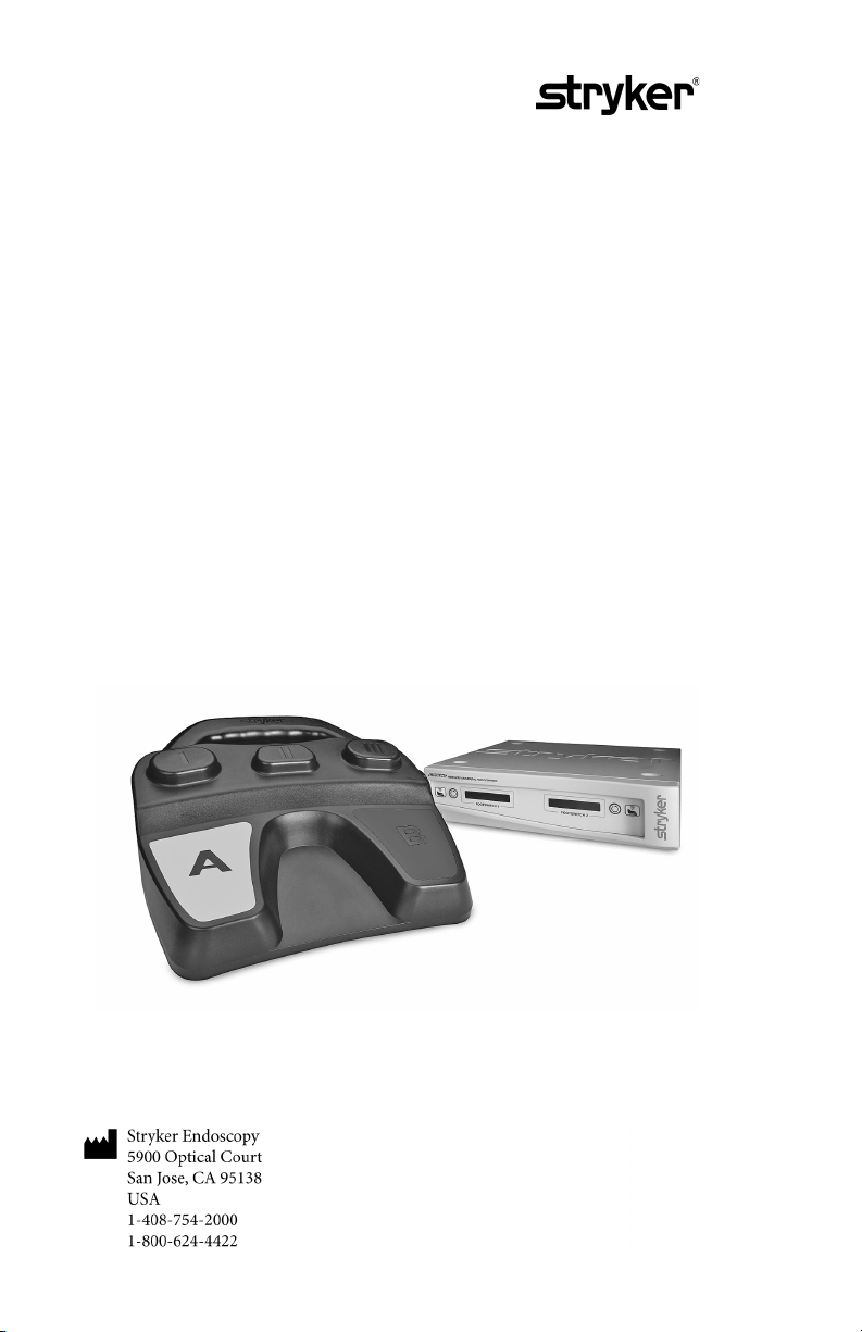
iSwitch
Wireless Universal
Foot Control
®
ireless Universal Foot Control
Operation and Maintenance Manual
PATENTS PENDING
Page 6

Table of Contents
Warnings and Cautions ..........................................................................3
Symbol Definitions .................................................................................4
Product Description and Intended Use ..................................................6
The Footswitch..................................................................................7
The Receiver ......................................................................................8
Front Panel ...................................................................................................... 8
Rear Panel ........................................................................................................ 9
Setting up the iSwitch............................................................................10
Setting Up the Receiver...................................................................10
Setting Up the Footswitch ..............................................................11
System Settings ......................................................................................12
To enter the Settings mode.............................................................12
Settings ........................................................................................................... 12
Exiting Settings Mode .................................................................................. 12
Operating the iSwitch System ...............................................................13
Using the Footswitch Controls .......................................................13
TPS Mode ...................................................................................................... 13
SERFAS Mode............................................................................................... 14
Using the Receiver Controls ...........................................................14
Selecting which device the footswitch will control .................................. 14
Unsychronizing footswitches...................................................................... 14
Monitoring battery life................................................................................. 14
Cleaning and Maintenance ...................................................................15
Cleaning ..........................................................................................15
Maintenance....................................................................................15
Replacing the Batteries ...................................................................15
Battery Disposal ..............................................................................15
Troubleshooting ....................................................................................16
Technical Specifications........................................................................17
Electromagnetic Compatibility.............................................................19
Warranty................................................................................................23
Service and Claims ................................................................................23
2
Page 7
Warnings and Cautions
WARNING The personal safety of the patient or physician may be
involved. Disregarding this information could result in
injury to the patient or physician.
Caution Special service procedures or precautions must be followed to
avoid damaging the instrument.
Note Special information to make maintenance easier or important
information more clear.
An exclamation mark within a triangle is intended to alert the
user to the presence of important operating and maintenance
instructions in the literature accompanying the product.
A lightning bolt within a triangle is intended to warn of the
presence of hazardous voltage. Refer all service to authorized
personnel.
Please read this manual and follow its instructions carefully. The words warning,
caution, and note carry special meanings and should be carefully reviewed:
WARNING To avoid injury to the user and the patient and/or damage to
this device, the user must:
1. Read this operating manual thoroughly and be familiar with its contents
prior to using this equipment.
2. Carefully unpack the unit and check if any damage occurred during
shipment. If damage is detected, please refer to the Service section in this
manual.
3. Avoid removing covers on the unit and attempting internal repairs or
adjustments not specifically detailed in this operating manual.
4. Pay close attention to the care and cleaning instructions in this manual.
A deviation may cause damage to the device.
5. Never sterilize the Wireless Universal footswitch components.
6. Be completely familiar and comfortable with the operation of the
Wireless Universal footswitch. Training may be required before some
operators are thoroughly familiar with how to properly operate the
footswitch.
3
Page 8
7. When the Receiver is interconnected with other medical electrical
equipment, leakage currents may be additive. Ensure all systems are
installed according to the requirements of IEC 60601-1-1.
8. Disconnect the footswitch from the Receiver when removing it from a
room. (Power the Receiver off, or hold the Receiver mode button for
3 seconds). Failure to disconnect the footswitch may result in accidental
activation of a device by the footswitch when within range of the
Receiver.
The Wireless Universal footswitch warranty is void if any of these warnings are
disregarded.
WARNING Federal law (United States of America) restricts this device to use
by, or on order of, a physician.
Stryker Endoscopy reserves the right to make improvements to the product
described herein. The product therefore may not agree in detail to the published
design or specifications. All specifications are subject to change without notice.
Please contact your local Stryker Endoscopy Distributor listed in the Other
Service section or phone your local Stryker Endoscopy sales representative or
agent for information on changes and new products.
Symbol Definitions
Humidity Limitation
Temperature Limit
Catalog Number
Quantity
Federal (USA) law restricts this device to sale by or on
the order of physician.
Manufacturer
Date of Manufacture
4
Page 9
Attention, consult instructions for use
Serial Number
Authorized representative in the European community
IXP7 Protected against immersion up to 1 m
Indicates that the device complies with the applicable
standard and establishes a traceable link between the
device and the manufacturer, importer or their agent
responsible for compliance and for placing it on the
Australian market.
Technical Conformity Mark for Japan
Alternating current
Protective Earth Ground
Equipotentiality
Denotes compliance to CSA 22.2 No.601.1-M90 and
UL60601-1.
This symbol indicates that the waste of electrical and
electronic equipment must not be disposed as unsorted
municipal waste and must be collected separately.
Please contact the manufacturer or other authorized
disposal company to decommission your equipment.
5
Page 10

Product Description and
Intended Use
The Stryker Wireless Universal footswitch system is a wireless remote-control
system that centralizes control of the various footswitch-operated devices found
in the operating room.
The iSwitch™ is intended for use in surgical procedures where footswitchoperated devices, such as the Stryker TPS or SERFAS systems, are normally used.
The iSwitch™ consolidates the functions of these devices into one wireless
footswitch, freeing the operating room from excessive cables and foot controls.
The iSwitch consists of two main components:
1. A wireless footswitch, which provides pedals similar to those found on
other footswitches and transmits radio signals to a radio receiver console
2. A radio receiver console, which routes commands from the footswitch
to devices that connect to the receiver’s rear panel.
Each component and its functions are described in the following pages.
Note The iSwitch is a wireless footswitch designed to replace multiple
wired footswitches that surgeons are accustomed to using.
Operators should ensure that they are completely familiar and
comfortable with the operation of the device. Training may be
required before some operators are thoroughly familiar with how
to properly operate the footswitch. Users should be sure that they
have received adequate training before using this device in
surgical practice.
Note It is recommended to have a wired footswitch available in case of
electromagnetic interference problems with the wireless
connection.
This device includes RF transmitters and emits non-ionizing radiation.
This device complies with Part 15 of the FCC rules. Operation is subject to the
following two conditions: (1) this device may not cause harmful interference, and
(2) this device must accept any interference received, including interference that
may cause undesired operation. See the “Electromagnetic Compatibility” section
of this manual for more information.
To prevent radio interference with any licensed service, this device is intended to
be operated indoors and away from windows to provide maximum shielding.
This device complies with FCC RF exposure limits set for indoor use only. Do
not co-locate this device in close proximity to another transmitter antenna.
6
Page 11
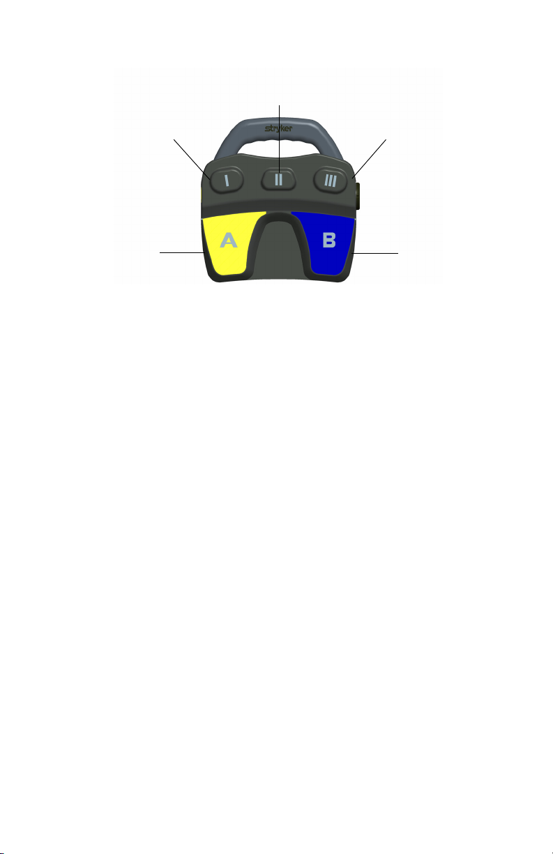
The Footswitch
1
2
4
5
6
3
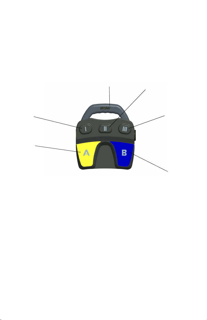
The footswitch rests on the operating-room floor and provides foot control of all
devices connected to the iSwitch system. The footswitch houses three buttons
and two pedals, which enable the user to alternate between operating-room
devices and perform device-specific functions. When a button or pedal is pressed,
the footswitch transmits a radio signal to the receiver, where the command is then
routed to the appropriate device.
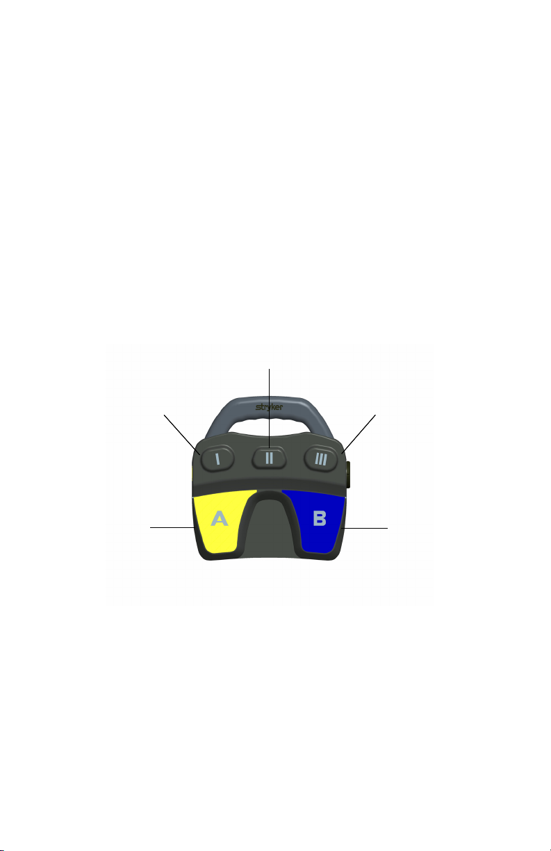
The footswitch and its features are described in Figure 1 below.
Figure 1: The footswitch
1. Footswitch Handle
2. Button II (Mode Button): Selects which device the footswitch will
control. See the “System Settings” section of this manual for Mode
options.
Note Button/pedal function for all other buttons and pedals depends
on which operating-room device, or “mode,” is selected. See the
“Using the footswitch controls” section in this manual for devicespecific button functions.
3. Button III
4. Pedal B
5. Pedal A
6. Button I
7
Page 12
The Receiver
1
2
3
4
5
6
7
The receiver connects to the devices that will be controlled by the iSwitch system.
It receives commands sent from the footswitch and routes them to the appropriate
device. The receiver also determines how footswitches are used and which devices
they will control.
The features of the receiver are listed in Figures 2 and 3.
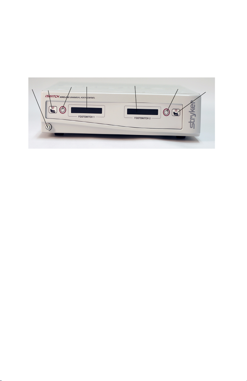
Figure 2: The receiver front panel
Front Panel
1. Power Switch: Powers on and off the receiver. The switch will illuminate
when the unit is on.
2. Synchronize port 1: Enables a footswitch to work with the receiver
when aligned with the synchronize logo on that footswitch. The
footswitch will be designated as “footswitch 1.”
3. Mode button 1: Selects which device footswitch 1 will control (which
“mode” the footswitch is in). Pressing and holding this button will clear
the Footswitch.
4. Active-device display 1: Displays which device is currently active and
can be controlled by footswitch 1 (which “mode” footswitch 1 is in).
5. Active-device display 2: Displays which device is currently active and
can be controlled by footswitch 2 (which “mode” footswitch 2 is in).
6. Mode button 2: Selects which device footswitch 2 will control (which
“mode” the footswitch is in). Pressing and holding this button will clear
the Footswitch
7. Synchronize port 2: Enables a second footswitch to work with the
receiver when aligned with the synchronize logo on that footswitch. The
footswitch will be designated as “footswitch 2.”
8
Page 13
Rear Panel
12
3
4
5
6
7
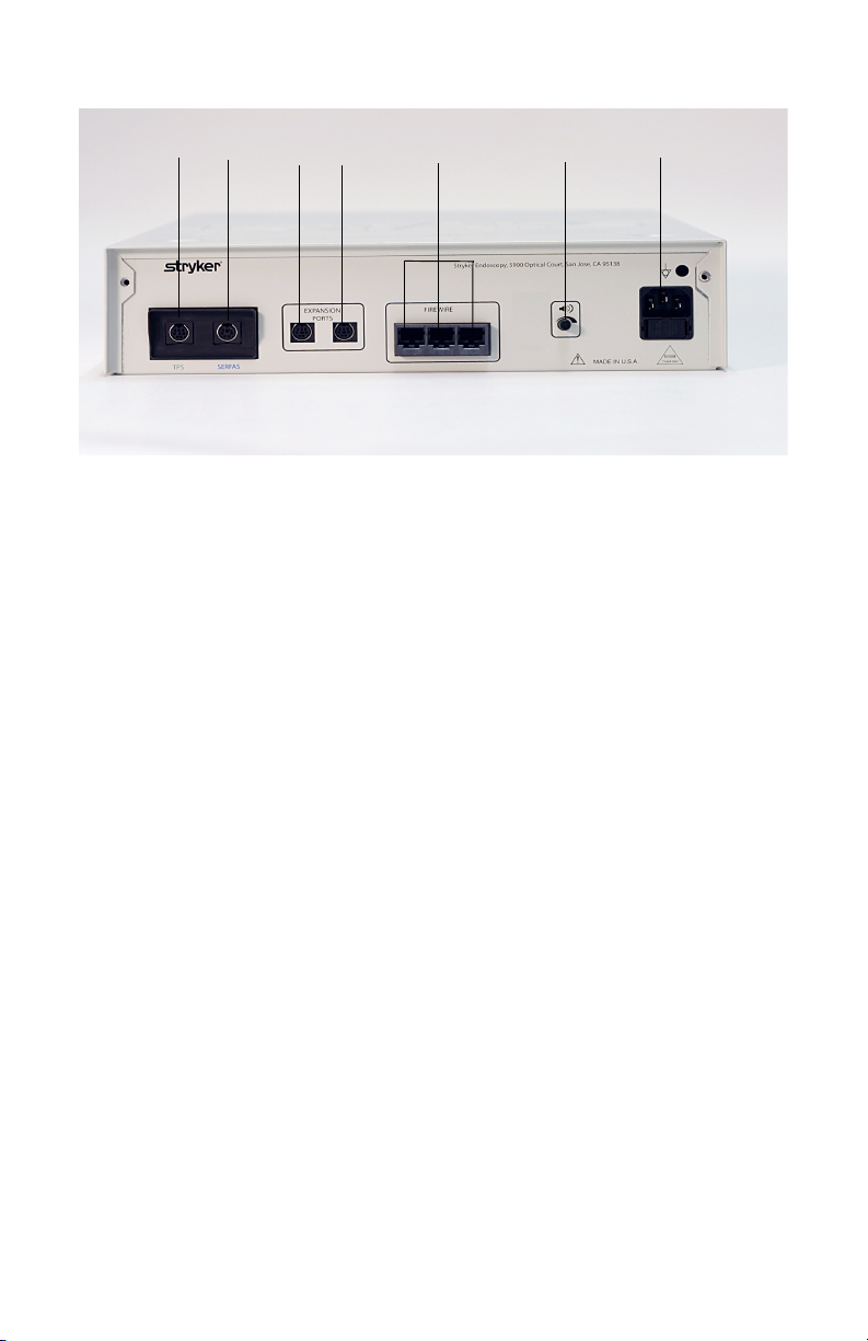
Figure 3: The receiver rear panel
1. TPS output: Provides a dedicated connection to the TPS console,
enabling the commands issued from the footswitch to be routed to the
TPS console.
2. SERFAS output: Provides a dedicated connection to the SERFAS
console, enabling the commands issued from the footswitch to be routed
to the SERFAS console.
3. Expansion port: Provides a generic connection to addition devices,
enabling the commands issued from the footswitch to be routed to the
console.
4. Expansion port: Provides a generic connection to addition devices,
enabling the commands issued from the footswitch to be routed to the
console.
5. SFB Serial Connectors: Enables firewire connection with newer
devices, such as CORE and SERFAS Energy, eliminating the need for
multiple connection cables.
6. Volum e co ntrol : Controls the output volume.
7. AC-power input: Connects to the AC Power cord, which connects to a
hospital-grade power outlet.
9
Page 14
Setting up the iSwitch
footswitch Receiver
TPS Console
SERFAS Console
Note Devices may also
be connected
directly to the
iSwitch Receiver.
Setting Up the Receiver
1. Position the receiver on a Stryker cart or other sturdy platform.
2. Connect the AC Power.
• Connect the AC power cord to the AC input on the rear receiver
panel.
• Connect the other end to a hospital-grade receptacle.
3. Connect the devices that will be controlled by the footswitch System.
• For older TPS and SERFAS consoles, connect a device cable to the
appropriate port on the rear receiver panel, and then connect the other
end to the footswitch port on the front console panel.
• For newer CORE and SERFAS Energy consoles, connect a firewire
cable to the firewire port on the rear receiver panel, and then connect
the other end to the firewire port on the console rear panel.
Contact your local Stryker Representative for applicable device cable
part numbers.
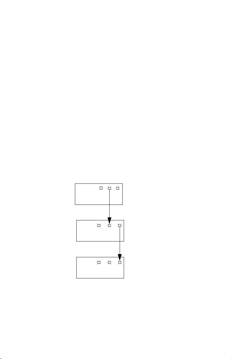
Note When connecting devices to the footswitch receiver SFB serial
cable, connect the devices in series (see Figure 4 below).
Figure 4: Connecting devices in series to the footswitch receiver
4. Power on the receiver and all devices connected to it.
10
Page 15

Setting Up the Footswitch
1. Insert the Stryker Battery Pack (P/N 277-300-100).
Note It is recommended to use the Stryker Battery Pack to achieve
maximum battery life and prevent improper insertion.
• Twist off the cap on the side of the footswitch by turning 1/2 turn
counterclockwise.
• Insert the batteries.
• Replace the cap and lock in place by turning 1/2 turn clockwise.
2. Synchronize the footswitch with the receiver.
• Press buttons I and III simultaneously and release.
• Align the footswitch synchronize logo with the footswitch 1
synchronize logo on the receiver.
• Hold the footswitch one inch away from the receiver. The LED will
appear red while synchronization is in process, and will change to
green when the footswitch has been synchronized.
3. Synchronize a second footswitch if needed.
• Press buttons I and III simultaneously and release.
• Align the second footswitch synchronize logo with the footswitch 2
synchronize logo on the receiver.
• Hold the footswitch one inch away from the receiver. The LED
indicator will change to green when the footswitch has been
synchronized.
Note A single footswitch cannot be synchronized to two channels.
4. Position the footswitch on the floor where it can be comfortably
accessed.
Note The Footswitch needs to be synchronized when a Receiver is
powered on or when the Footswitch enters a new room. A
Footswitch is disconnected from the Receiver by powering off the
Receiver or pressing and holding the Receiver Mode button.
11
Page 16

System Settings
Using the 2 mode buttons on the Receiver, the system Settings may be modified as
listed below:
To enter the Settings mode
Press and hold both mode buttons on the Receiver for 5 seconds
• In this mode, the left (Footswitch 1) mode button toggles among
options.
• In this mode, the right (Footswitch 2) button enables or disables the
settings.
Settings
Speed Mode (Default: Disabled)
• When enabled, a single press of button II on the Footswitches changes
the mode.
• When disabled, press and hold to select the device.
Note If using 2 handpieces in Speed Mode, press and hold the Mode
button to change handpieces.
Tea che r Mo de (Default: Disabled)
• When enabled, 2 Footswitches may select the same device. Pressing
button II on either Footswitch will give it primary control. To transfer
control, simply press button II on the second Footswitch.
• When disabled, the Footswitch will function as normal. Only one
Footswitch will control the selected device.
Global Merge (Default: Disabled)
• When enabled, two Footswitches may select the same device. The
Footswitch pressed first will receive primary control. Control may
then alternate between Footswitches when the pedals on the primary
Footswitch are not pressed and the pedals on the second Footswitch
are depressed.
• When disabled, the Footswitch will function as normal. Only one
Footswitch will control the selected device.
Exiting Settings Mode
To exit the Settings Mode, press and hold both Mode buttons for 5 seconds. The
selected settings will remain unchanged.
12
Page 17
Operating the iSwitch System
Reverse
Select Device*
(SERFAS, TPS, etc.)
Reverse
High/Low
Oscillate/Forward
or Reverse
Forward
*In Speed Mode, press to select the device. Press and hold to change the
handpiece.
Note Using Stryker disposable bags (P/N 277-500-100) is
recommended to keep the footswitch clean during use. Contact
your local Stryker representative for ordering information.
The iSwitch system is operated through the controls on the footswitch and the
controls on the receiver.
Using the Footswitch Controls
1. Press the mode button to select which device the footswitch will control.
The footswitch buttons will perform according to the mode selected.
TPS Mode
Note The Wireless Universal footswitch can be programmed like the
TPS Wired footswitch. Default controls are shown.
Figure 5: Default controls of the Wireless Footswitch in TPS Mode
13
Page 18
SERFAS Mode
Cut
Coag
Increase Cut Level
Select Device*
(SERFAS, TPS, etc.)
Decrease Cut Level
Figure 6: Default controls of the Wireless Footswitch in SERFAS Mode
Using the Receiver Controls
While the footswitch controls the devices connected to the iSwitch system, the
receiver controls how the footswitch functions. Receiver controls are used for
selecting which device the footswitch will control, unsynchronizing footswitches,
and merging footswitches.
Selecting which device the footswitch will control
Press the mode button to toggle through the connected devices. The selected
device will appear on the display screen.
Note Mode button 1 selects the devices footswitch 1 will control; mode
button 2 selects the devices footswitch 2 will control.
Note The device can also be selected by pressing the mode button on
the footswitch.
Unsychronizing footswitches
Press and hold the mode button to disable communication between a footswitch
and the receiver. After the footswitch has been unsynchronized, the footswitch
will not function again until it is resynchronized with the receiver.
Monitoring battery life
The receiver will provide feedback to alert the user when the remaining battery
life is low. The receiver will emit an audible warning and the receiver LED will
flash red.
In this event, replace the battery pack after the current case
has finished.
Note It is recommended to use the Stryker Battery Pack
(P/N 277-300-100).
14
Page 19

Cleaning and Maintenance
Cleaning
WARNING Unplug the receiver from the electrical outlet before cleaning
the unit.
Caution Do not immerse the footswitch in any liquid, as product
damage may result.
Caution Do not use solvents, such as alcohol, or cleaning solutions that
contain ammonia to clean the footswitch, as product damage
may result.
Caution Do not sterilize the footswitch or receiver, as product damage
will result.
1. Wipe the footswitch with a soft cloth dampened in a mild cleaning
solution.
2. Clean the footswitch with disinfectant if needed.
Maintenance
The Wireless Universal footswitch system requires no preventative or periodic
maintenance.
WARNING Remove the batteries if the Footswitch is not in use for an
extended period of time.
WARNING To reduce the risk of electrical shock, do not open the
footswitch. There are no user-serviceable components
inside. Should service be needed, notify your local Stryker
representative.
Replacing the Batteries
WARNING Replace the batteries only when outside the patient’s vicinity.
Caution The batteries may explode or leak if recharged, inserted
improperly, or disposed of by fire.
Note Replace the battery pack with a Stryker Battery Pack (P/N 277-
300-100) for optimal battery performance.
Battery Disposal
The batteries must be disposed of according to local laws and hospital practices.
15
Page 20

Troubleshooting
Problem Possible Solution
No results when the
Footswitch is pressed.
The Footswitch will not
synchronize with the
receiver.
The receiver does not
indicate that a device is
attached upon startup.
Footswitch 2 is stuck using
the same device as
Footswitch 1.
Cannot hear audio
messages.
When synching the
Footswitch, the LED on the
Receiver does not change
color and synching fails.
• Press buttons I or III to wake Footswitch.
•Synchronize the Footswitch.
• Replace batteries.
• Hold the Footswitch synchronization icon
within one inch of the receiver synchronization icon.
• Press buttons I and III simultaneously and
release.
• Replace batteries and try again.
• Ensure the device is connected to the correct input on the rear receiver panel.
• Press the mode button to unmerge the
Footswitches.
• Increase volume using control on rear of
receiver.
• If another Footswitch is already synched to
this channel, press and hold the Mode button on the Receiver for 5 seconds to clear
the existing Footswitch.
• Synch the new Footswitch.
The Footswitch will not
synchronize with the
Receiver. An adjacent
Receiver is present.
The Receiver displays
“Replace batteries” even
though new batteries have
been inserted
16
• Press buttons I and III simultaneously and
release to disconnect the Footswitch from
the adjacent Receiver.
• Synch the Footswitch to the new Receiver.
• Batteries may be inserted incorrectly. Reinsert batteries.
Page 21

Technical Specifications
Environmental Specifications
Operating Temperature: 0° to 40°C
Humidity: 30% to 75% RH
Shipping/Storage
Operating Temperature: 0° to 40°C
Humidity: 30% to 75% RH
System Input Power Requirements
Voltage: 100 – 240 VAC
Frequency: 50/60 Hz
Current: 0.6 Amps
Fuse Rating:
Classifications
1.0A/250V
Receiver: Class I Equipment Footswitch
• No Applied Parts
• Water Ingress Protection,
IPXO
• Continuous Operation
•Internally powered
•No Applied Parts
• Water Ingress Protection,
IPX7
• Continuous Operation
Wireless USB Specifications
Frequency range: 2.402 GHz – 2.478 GHz
Note: Units shipped to Australia operate in
the 2.402 GHz – 2.463 GHz frequency range.
Modulation: Direct Sequence Spread Spectrum
(DSSS)
Power: 0 dBm
17
Page 22

RFID Specifications
Frequency range: 125 KHz
Modulation: Binary Pulse Length Modulation
(BPLM)
Power: <0.001W
FCC ID
SSH-WUF
IC ID
4919C-WUF
18
Page 23
Electromagnetic Compatibility
Like other electrical medical equipment, the iSwitch requires special precautions
to ensure electromagnetic compatibility with other electrical medical devices. To
ensure electromagnetic compatibility (EMC), the iSwitch must be installed and
operated according to the EMC information provided in this manual.
Note The iSwitch has been designed and tested to comply with IEC
60601-1-2:2001 requirements for EMC with other devices.
Caution The iSwitch may be interfered with by other equipment,
including portable and mobile RF communication equipment,
even if such equipment meets the applicable emissions
requirements.
WARNING Do not use cables or accessories other than those provided
with the iSwitch, as this may result in increased
electromagnetic emissions or decreased immunity to such
emissions.
WA RN I N G If the iSwitch is used adjacent to or stacked with other
equipment, observe and verify normal operation of the
iSwitch in the configuration in which it will be used prior to
using it in a surgical procedure. Consult the tables below for
guidance in placing the iSwitch.
Guidance and Manufacturer's Declaration: Electromagnetic Emissions
iSwitch is intended for use in the electromagnetic environment specified below. The customer or the user of
Emissions test Compliance Electromagnetic Environment - guidance
RF emissions
CISPR11
RF emissions
CISPR11
Harmonic emissions
IEC61000-3-2
Vol tage Fluctu ations /
flicker emissions
IEC61000-3-3
iSwitch should ensure that it is used in such an environment.
Group 1 The iSwitch must emit electromagnetic energy in
Class B iSwitch is suitable for use in all establishments,
Class A
Complies
order to perform its intended function. NEarby elec-
tronic equipment may be affected.
including domestic establishments and those directly
connected to the public low-voltage power supply
network that supplies buildings used for domestic
purpos es.
19
Page 24

Guidance and Manufacturer's Declaration: Electromagnetic Immunity
iSwitch is intended for use in the electromagnetic environment specified below. The customer or
Immunity Test
Electrostatic Discharge (ESD)
IEC61000-4-2
Electrical fast transient/burst
IEC61000-4-4
IEC61000-4-5
Voltage dips, short interrup-
tions and voltag e variations on
power supply input lines
IEC61000-4-11
Power frequency (50/60Hz)
magnetic field
IEC 61000-4-8
the user of iSwitch should ensure that it is used in such an environment.
IEC 60601 Test
Level
±6kV contact
±8kV air
±2kV for power sup-
ply lines
±1kV for input/out-
put lines
Surge
NOTE: Ut is the a.c. mains voltage prior to application of the test level.
±1kV differential
mode
±2kV common mode
<5% Ut (>95% dip in
Ut) for 0.5 cycle
40% Ut (60% dip in
Ut) for 5 cycles
70% Ut (30% dip in
Ut) for 25 cycles
<5% Ut (>95% dip in
Ut) for 5 sec.
3 A/m
Compliance Level
±2,4,6kV contact
±2,4,8kV air
±2kV line to ground
±1kV line to line
±0.5, 1kV differential
mode
±0.5, 1, 2kV common
mode
<5% Ut (>95% dip in
Ut) for 0.5 cycle
40% Ut (60% dip in
Ut) for 5 cycles
70% Ut (30% dip in
Ut) for 25 cycles
<5% Ut (>95% dip in
Ut) for 5 sec.
3 A/m
Electromagnetic
Environment:
Guidance
Floors should be
wood, concrete, or
ceramic tile. If floors
are covered with syn-
thetic material, the rel-
ative humidity should
be at least 30%.
Mains power quality
should be that of a typ-
ical commercial or
hospital environment.
Mains power quality
should be that of a typ-
ical commercial or
hospital environment.
Mains power quality
should be that of a typ-
ical commercial or
hospital environment.
If the user of iSwitch
requires continued
operation during
power mains interrup-
tions, it is recom-
mended that iSwitch
be powered from an
uninterruptible power
supply or a battery.
Power-frequency mag-
netic fields should be
at levels characteristic
of a typical location in
a typical commercial
or hospital environ-
ment.
20
Page 25

Guidance and Manufacturer's Declaration: Electromagnetic Immunity
d1.17P=
d1.17P=
d2.33P=
iSwitch is intended for use in the electromagnetic environment specified below. The customer or
Immunity Test IEC 60601 Test Level
Conducted RF
IEC 61000-4-6
Radiated RF
IEC 61000-4-3
the user of iSwitch should ensure that it is used in such an environment.
3 Vrms
150 kHz to 80 MHz
3 V/m
80MHz to 2.5 GHz
Compliance
Level
3 V
3 V/m
Electromagnetic Environment: Guidance
Portable and mobile RF communications
equipment should be used no closer to any
part of the iSwitch system, including its cables,
than the recommended separation distance
calculated from the equation applicable to the
frequency of the transmitter.
Recommended Separation Distance
where P is the maximum output power rating
of the transmitter in watts (W) according to
the transmitter manufacturer and d is the rec
ommended separation distance in meters (m).
Field strengths from fixed RF transmitters, as
determined by an electromagnetic site survey
(a)
, should be less than the compliance level in
each frequency range
Interference may occur in the vicinity of
equipment marked with the following symbol:
80 MHz to 800 MHz
800 MHz to 2.5 GHz
(b)
.
-
NOTE 1: At 80 MHz and 800 MHz, the higher frequency range applies.
NOTE 2: These guidelines may not apply in all situations. Electromagnetic propagation is affected by absorption
(a) Field strengths from fixed transmitters, such as base stations for radio (cellular/cordless) telephones and land
mobile radios, amateur radio, AM and FM radio broadcast, and T V broadcast, cannot be predicted theoretically
with accuracy. To assess the electromagnetic environment due to fixed RF transmitters, an electromagnetic site
survey should be considered. If the measured field strength in the location in which the iSwitch system is used
exceeds the applicable RF compliance level above, the iSwitch system should be observed to verify normal
operation. If abnormal performance is observed, additional measures may be necessary, such as reorienting or
(b) Over the frequency range 150 kHz to 80 MHz, field strengths should be less than 3 V/m.
and reflection from structures, objects, and people.
relocating the iSwitch unit.
21
Page 26

Recommended Separation Distances Between Portable and Mobile RF Communications
d1.17P=
d1.17P=
d2.33P=
Equipment and the iSwitch System
The iSwitch system is intended for use in an electromagnetic environment in which radiated RF disturbances are
controlled. The user of the iSwitch system can help prevent electromagnetic interference by maintaining a mini
mum distance between portable and mobile RF communications equipment (transmitters) and the iSwitch sys-
tem as recommended below, according to the maximum output power of the communications equipment.
Separation distance (m) according to frequency of transmitter
Rated maximum output
power (W) of transmitter
150 kHz to 80
MHz
0.01 0.12 0.12 0.23
0.1 0.37 0.37 0.74
1 1.17 1.17 2.33
10 3.70 3.70 7.37
100 11.70 11.70 23.30
For transmitters rated at a maximum output power not listed above, the recommended separation distance (d) in
meters (m) can be estimated using the equation applicable to the frequency of the transmitter, where P is the
maximum output power rating of the transmitter in watts (W) according to the transmitter manufacturer.
NOTE 1: At 80 MHz and 800 MHz, the separation distance for the higher frequency range applies.
NOTE 2: These guidelines may not apply in all situations. Electromagnetic propagation is affected by absorption
and reflection from structures, objects, and people.
80 MHz to 800
MHz
800 MHz to 2.5
GHz
-
22
Page 27

Warranty
This Stryker Endoscopy product is warranted to the original purchaser for a
period of one year from the date of purchase to be free from defects in material
and workmanship. This warranty extends to all purchases and is limited to the
repair or replacement of the product without charge when returned to:
Stryker Endoscopy
5900 Optical Court
San Jose, CA 95138
USA
Stryker Endoscopy cannot accept responsibility for returns or replace-ments
which have not been authorized. This warranty does not cover damages caused by
misuse (i.e. neglect, dropping, or denting) or by failure to follow the procedures
outlined in this manual or demonstrated by Stryker Endoscopy representatives.
Unauthorized repair or modifications to the iSwitch may void the warranty and
invalidate the user’s authority to use the product.
There are no other expressed warranties.
Service and Claims
Caution Do not attempt to service this product yourself. If service is
needed either during or after the warranty period:
1. Contact Stryker Endoscopy at 1-800-624-4422, or phone your local
Stryker Endoscopy sales representative.
2. Clean and sterilize all parts that will be returned for service. Follow the
instructions provided in this manual.
3. Package all the components carefully in the original shipping container
if possible.
4. Ship the unit, pre-paid and insured to:
Stryker Endoscopy Customer Service
Attention: Repair Department
5900 Optical Court
San Jose, CA 95138
Note The product described in this manual is continually being
reviewed, and improvements may be made without notice.
Stryker and Stryker Endoscopy are registered trademarks of Stryker Corporation.
23
Page 28

Page 29
iSwitch
Universal-FunkFußsteuerung
®
Universal-Funk-Fußsteuerung
Bedienungs- und Wartungshandbuch
PATENTE ANGEMELDET
Page 30

Inhaltsverzeichnis
Warnhinweise und Vorsichtsmaßnahmen...........................................27
Erläuterung der Symbole ......................................................................28
Produktbeschreibung und Verwendungszweck ...................................31
Der Fußschalter ..............................................................................32
Der Empfänger................................................................................33
Gerätevorderseite.......................................................................................... 33
Geräterückseite ............................................................................................. 34
Einrichten des iSwitch-Systems ............................................................36
Einrichten des Empfängers.............................................................36
Einrichten des Fußschalters ...........................................................37
Systemeinstellungen ..............................................................................39
Aufrufen des Einstellungsmodus ...................................................39
Einstellungen................................................................................................. 39
Beenden des Einstellungsmodus ................................................................ 39
Bedienung des iSwitch-Systems ............................................................40
Bedienung über den Fußschalter....................................................40
TPS-Modus.................................................................................................... 40
SERFAS-Modus ............................................................................................ 41
Einsatz der Empfängerbedienelemente..........................................41
Wählen des vom Fußschalter zu steuernden Geräts ............................... 41
Aufheben der Fußschaltersychronisierung............................................... 41
Kontrollieren des Batteriezustands ............................................................ 42
Reinigung und Wartung .......................................................................43
Reinigung ........................................................................................43
Wartung ..........................................................................................43
Batteriewechsel ...............................................................................43
Batterieentsorgung .........................................................................44
Fehlerbehebung .....................................................................................45
Technische Daten ..................................................................................46
Elektromagnetische Verträglichkeit .....................................................48
Garantie .................................................................................................53
Kundendienst und Garantieansprüche ................................................53
26
Page 31

Warnhinweise und
WARNHINWEIS Diese Hinweise betreffen die Sicherheit des Patienten
oder des Arztes. Wenn diese Informationen nicht
beachtet werden, können Arzt oder Patient
Verletzungen erleiden.
Achtung Diese Hinweise enthalten besondere Wartungsverfahren und
Vorsichtsmaßnahmen, die beachtet werden müssen, um das
Gerät nicht zu beschädigen.
Hinweis Hierbei handelt es sich um Anmerkungen, die die Wartung
vereinfachen oder wichtige Informationen verdeutlichen.
Das Ausrufezeichen in einem Dreieck soll den Benutzer auf
wichtige Bedienungs- und Wartungsanweisungen in der
Begleitdokumentation des Produkts hinweisen.
Der Blitz in einem Dreieck kennzeichnet eine Warnung vor
gefährlicher Spannung. Alle Wartungsarbeiten dürfen nur von
autorisiertem Personal durchgeführt werden.
Vorsichtsmaßnahmen
Dieses Handbuch sorgfältig durchlesen und genau an die darin enthaltenen
Anweisungen halten. Die Wörter Warnung, Vorsicht und Hinweis kennzeichnen
wichtige Stellen dieses Handbuchs, die besonders zu beachten sind:
WARNHINWEIS Zur Vermeidung ernsthafter Verletzungen von
1. Lesen Sie vor dem Einsatz dieses Geräts dieses Handbuch gründlich
2. Das Gerät vorsichtig auspacken und auf eventuelle Versandschäden
3. Möglichst keine Geräteabdeckungen entfernen und keine inneren
4. Die Pflege- und Reinigungsanweisungen in diesem Handbuch
durch und machen Sie sich mit dem Inhalt vertraut.
überprüfen. Sollten Beschädigungen festgestellt werden, bitte den
Kundendienst-Abschnitt dieses Handbuchs einsehen.
Reparaturen oder Einstellungen vornehmen, die in diesem Handbuch
nicht ausdrücklich aufgeführt sind.
müssen genau eingehalten werden. da andernfalls das Gerät beschädigt
werden kann.
Benutzer und Patient und/oder von Beschädigungen
am Gerät muss der Benutzer Folgendes tun:
27
Page 32

5. Die Komponenten des Universal-Funkfußschalters niemals sterilisieren.
6. Sich mit der Bedienung des Universal-Funkfußschalters vollständig
vertraut und versiert machen. Manche Anwender erfordern evtl.
eine Schulung, um sich gründlich mit der einwandfreien
Fußschalterbedienung vertraut zu machen.
7. Ist der Empfänger mit anderen medizinischen elektrischen Geräten
verbunden, können sich Kriechströme summieren. Sicherstellen,
dass alle Systeme entsprechend den Anforderungen der IEC-Norm
60601-1-1 installiert sind.
8. Beim Entfernen aus einem Raum den Fußschalter vom Empfänger
trennen. (Den Empfänger ausschalten oder die Modustaste des
Empfängers 3 Sekunden lang gedrückt halten). Wird der Fußschalter
nicht vom Empfänger getrennt, kann dies im Einzugsbereich des
Empfängers zur versehentlichen Aktivierung eines Geräts durch den
Fußschalter führen.
Werden einer oder mehrere dieser Warnhinweise nicht beachtet, erlischt die
Garantie des Universal-Funkfußschalters.
WARNHINWEIS Die Bundesgesetzgebung der USA schreibt vor, dass dieses
Gerät nur von einem Arzt oder auf ärztliche Anordnung
verwendet werden darf.
Stryker Endoscopy behält sich das Recht vor, Verbesserungen des hier
beschriebenen Produkts vorzunehmen. Das Produkt muss deshalb nicht in allen
auslegungsspezifischen oder technischen Einzelheiten mit den veröffentlichten
Daten übereinstimmen. Alle technischen Daten können ohne vorherige
Ankündigung geändert werden. Bezüglich Angaben zu Änderungen und neuen
Produkten bitte an den zuständigen Stryker Endoscopy-Fachhändler wenden
(siehe den Abschnitt „Sonstige Kundendienststellen“) oder telefonisch an den
zuständigen Stryker Endoscopy-Vertreter.
Erläuterung der Symbole
Bereich der Luftfeuchtigkeit
Temperaturgrenzwerte
Artikelnummer
28
Page 33

Menge
Laut US-Bundesgesetz darf dieses Produkt nur
durch einen Arzt bzw. auf ärztliche Anordnung
verkauft werden.
Hersteller
Herstellungsdatum
Achtung, siehe Gebrauchsanweisung
Seriennummer
Bevollmächtigter Vertreter in der EG
IPX7 Schutz gegen zeitweiliges Untertauchen bis max. 1 m
Tiefe
Zeigt an, dass das Gerät der gültigen Norm entspricht
und setzt das Gerät und den Hersteller, Importeur
oder dessen Vertreter, der für Einhaltung und für
das Inverkehrbringen auf dem australischen Markt
verantwortlich ist, in einen nachvollziehbaren Bezug.
Kennzeichen für technische Konformität für Japan
Wechselstrom
Schutzerdung
Potenzialausgleich
Konformitätszeichen für CSA 22.2 Nr. 601.1-M90 und
UL60601-1
29
Page 34

Dieses Symbol bedeutet, dass von elektrischen und
elektronischen Geräten stammender Abfall nicht dem
Hausmüll zugeführt werden darf, sondern gesondert
entsorgt werden muss. Wenden Sie sich bezüglich der
Entsorgung des Produkts an den Hersteller oder an ein
entsprechendes Entsorgungsunternehmen.
30
Page 35

Produktbeschreibung
und Verwendungszweck
Das Universal-Funk-Fußschaltersystem von Stryker ist ein drahtloses
Fernsteuerungssystem für die zentrale Steuerung der verschiedenen per
Fußschalter bedienbaren Geräte im OP.
Das iSwitch™-System ist für den Einsatz bei chirurgischen Verfahren vorgesehen,
bei denen die Verwendung von per Fußschalter bedienbaren Geräten, wie bspw.
dem TPS- oder dem SERFAS-System von Stryker, üblich ist. Das iSwitch™-System
konsolidiert die Funktionen dieser Geräte in einem Funkfußschalter, wodurch
überflüssige Kabel und Fußsteuerungen im OP eliminiert werden.
Das iSwitch-System umfasst zwei Hauptkomponenten:
1. Einen Funkfußschalter, dessen Pedale denen anderer Fußschalter
gleichen. Dieser Fußschalter überträgt Funksignale an eine
Funkempfängerkonsole
2. Eine Funkempfängerkonsole, welche die Fußschalterbefehle an Geräte
weiterleitet, die an der Rückseite des Empfängers angeschlossen sind.
Die einzelnen Komponenten und deren Funktionen sind auf den folgenden
Seiten erläutert.
Hinweis Der iSwitch ist ein Funkfußschalter, der mehrere der verkabelten
Fußschalter ersetzt, mit denen Chirurgen gewöhnlich arbeiten.
Der Anwender muss sich mit der Bedienung des Geräts
vollkommen vertraut machen und in ihr versiert sein. Manche
Anwender erfordern evtl. eine Schulung, um sich gründlich
mit
der einwandfreien Fußschalterbedienung vertraut zu
machen. Der Benutzer muss vor dem Einsatz dieses Geräts
in
der chirurgischen Praxis sicherstellen, dass er hinreichend
geschult ist.
Hinweis Es wird angeraten, für den Fall elektromagnetischer Störungen
der Funkverbindung einen Fußschalter mit Kabelanschluss bereit
zu halten.
Dieses Gerät umfasst RF-Sender und emittiert nichtionisierende
Strahlung.
31
Page 36

Dieses Gerät erfüllt die Auflagen von Teil 15 der Vorschriften der US-
1
2
4
5
6
3
amerikanischen Funkaufsichtsbehörde FCC. Der Betrieb unterliegt den
folgenden beiden Bedingungen: (1) Dieses Gerät darf keine Störungen
verursachen, und (2) dieses Gerät muss alle eingehenden Störungen akzeptieren,
einschließlich Störungen, die zu unerwünschtem Funktionsverhalten führen
können. Siehe den Abschnitt „Elektromagnetische Verträglichkeit“ in diesem
Handbuch.
Zur Verhütung von Funkstörungen zugelassener Dienste ist dieses Gerät für den
Betrieb in Gebäuden und nicht in Fensternähe vorgesehen, um eine maximale
Abschirmung zu gewährleisten.
Dieses Gerät erfüllt nur die RF-Expositionsauflagen der FCC für den Betrieb
in Gebäuden. Dieses Gerät nicht in unmittelbarer Nähe anderer Sendeantennen
aufstellen.
Der Fußschalter
Der Fußschalter wird auf dem OP-Boden platziert und ermöglicht die
Fußsteuerung aller an das iSwitch-System angeschlossenen Geräte. Der
Fußschalter besitzt drei Tasten und zwei Pedale, mit deren Hilfe der Benutzer
zwischen den OP-Geräten umschalten und gerätespezifische Funktionen
ausführen kann. Beim Drücken einer Taste oder eines Pedals überträgt der
Fußschalter ein Funksignal an den Empfänger, der den Befehl sodann an das
entsprechende Gerät weiterleitet.
Der Fußschalter und seine Merkmale werden im Folgenden mit
Abbildung 1 vorgestellt.
Abbildung 1: Der Fußschalter
32
Page 37

1. Fußschaltergriff
1
2
3
4
5
6
7
2. Taste II (Modustaste): Dient zum Wählen des vom Fußschalter zu
steuernden Geräts. Bezüglich der Modusoptionen bitte den Abschnitt
„Systemeinstellungen“ in diesem Handbuch einsehen.
Hinweis Die Tasten-/Pedalfunktionen aller übrigen Tasten und Pedale
sind abhängig vom gewählten OP-Gerät bzw. „Modus“. Bezüglich
gerätespezifischer Tastenfunktionen bitte den Abschnitt „Einsatz
der Fußschalter-Bedienelemente“ in diesem Handbuch einsehen.
3. Ta st e III
4. Pedal B
5. Pedal A
6. Ta st e I
Der Empfänger
Der Empfänger wird an die vom iSwitch-System zu steuernden Geräte
angeschlossen. Er empfängt Befehle vom Fußschalter und leitet sie an das
entsprechende Gerät weiter. Der Empfänger bestimmt auch die Einsatzweise der
Fußschalter und welche Geräte sie steuern.
Die Merkmale des Empfängers werden mit den Abbildungen 2 und 3 vorgestellt.
Abbildung 2: Die Empfängervorderseite
Gerätevorderseite
1. Netzschalter: Dient zum Ein- und Ausschalten des Empfängers.
Bei
2. Synchronisierungsanschluss 1: Ermöglicht bei Ausrichtung mit dem
Synchronisierungssymbol eines Fußschalters das Zusammenwirken des
betreffenden Fußschalters mit dem Empfänger. Der Fußschalter wird als
„Fußschalter 1“ bezeichnet.
eingeschaltetem Gerät leuchtet der Schalter.
33
Page 38

3. Modustaste 1: Dient zum Wählen des von Fußschalter 1 zu steuernden
12
3
4
5
6
7
Geräts (des „Modus“ des Fußschalters). Durch Drücken und
Gedrückthalten dieser Taste wird der Fußschalter gelöscht.
4. Geräteaktivierung-Anzeige 1: Zeigt an, welches Gerät aktuell aktiviert
ist und über Fußschalter 1 gesteuert werden kann (in welchem „Modus“
sich Fußschalter 1 befindet).
5. Geräteaktivierung-Anzeige 2: Zeigt an, welches Gerät aktuell aktiviert
ist und über Fußschalter 2 gesteuert werden kann (in welchem „Modus“
sich Fußschalter 2 befindet).
6. Modustaste 2: Dient zum Wählen des von Fußschalter 2 zu steuernden
Geräts (des „Modus“ des Fußschalters). Durch Drücken und
Gedrückthalten dieser Taste wird der Fußschalter gelöscht.
7. Synchronisierungsanschluss 2: Ermöglicht bei Ausrichtung mit
dem
Synchronisierungssymbol eines zweiten Fußschalters das
Zusammenwirken dieses zweiten Fußschalters mit dem Empfänger.
Der
Fußschalter wird als „Fußschalter 2“ bezeichnet.
Geräterückseite
Abbildung 3: Die Empfängerrückseite
1. TPS-Ausgang: Dient als dedizierter Anschluss für die TPS-Konsole,
so
dass Fußschalterbefehle an die TPS-Konsole geleitet werden können.
2. SERFAS-Ausgang: Dient als dedizierter Anschluss für die SERFAS-
Konsole, so dass Fußschalterbefehle an die SERFAS-Konsole geleitet
werden können.
34
Page 39

3. Erweiterungsanschluss: Dient als generischer Anschluss für zusätzliche
Geräte, so dass die Fußschalterbefehle an die Konsole geleitet werden
können.
4. Erweiterungsanschluss: Dient als generischer Anschluss für zusätzliche
Geräte so dass die Fußschalterbefehle an die Konsole geleitet werden
können.
5. Serielle SFB-Anschlüsse: Ermöglicht den Firewire-Anschluss neuerer
Geräte wie CORE und SERFAS Energy und eliminiert damit die
Notwendigkeit mehrerer Anschlusskabel.
6. Lautstärkeregler: Dient zum Regeln der Ausgabelautstärke.
7. We c hs e l st r o me i n ga n g : Anschluss für das Wechselstrom-Netzkabel, das
an eine für den Krankenhausbetrieb geeignete Steckdose angeschlossen ist.
35
Page 40

Einrichten des
iSwitch-Systems
Einrichten des Empfängers
1. Den Empfänger auf einem Wagen von Stryker oder auf einer anderen
stabilen Plattform platzieren.
2. Das Gerät an den Wechselstromanschluss anschließen.
• Das Wechselstrom-Netzkabel an den Wechselstromeingang an der
Empfängerrückseite anschließen.
• Das andere Kabelende an eine für den Krankenhausbetrieb geeignete
Steckdose anschließen.
3. Die vom Fußschaltersystem zu steuernden Geräte anschließen.
• Bei älteren TPS- und SERFAS-Konsolen ein Gerätekabel an den
entsprechenden Anschluss an der Empfängerrückseite anschließen
und das andere Ende an den Fußschalteranschluss an der
Konsolenvorderseite.
• Bei den neueren CORE- und SERFAS Energy-Konsolen ein Firewire-
Kabel an den Firewire-Anschluss an der Empfängerrückseite
anschließen und das andere Ende an den Firewire-Anschluss
an
der Konsolenrückseite.
Bezüglich der Bestellnummern für die jeweiligen Gerätekabel bitte
an den zuständigen Stryker-Vertreter wenden.
Hinweis Beim Anschließen von Geräten an das serielle SFB-Kabel des
Fußschalterempfängers sind die Geräte in Reihe zu schalten
(siehe Abbildung 4 im Folgenden).
36
Page 41

Abbildung 4: Reihenanschluss von Geräten am Fußschalterempfänger
Fußschalterempfänger
TPS-Konsole
SERFAS-Konsole
Hinweis Geräte können
auch direkt am
iSwitch-Empfänger
angeschlossen
werden.
4. Den Empfänger und alle daran angeschlossenen Geräte einschalten.
Einrichten des Fußschalters
1. Das Batteriebündel von Stryker (Bestell-Nr. 277-300-100) einlegen.
Hinweis Um eine maximale Batterielebensdauer zu gewährleisten und
inkorrektes Einlegen zu vermeiden, empfiehlt sich die
Verwendung des Batteriebündels von Stryker.
• Die seitliche Fußschalterkappe 1/2 Umdrehung entgegen dem
Uhrzeigersinn drehen und dadurch entfernen.
• Die Batterien einlegen.
• Die Kappe wieder anbringen und durch 1/2 Umdrehung im
Uhrzeigersinn arretieren.
2. Den Fußschalter mit dem Empfänger synchronisieren.
• Die Tasten I und III gleichzeitig drücken und anschließend wieder
freigeben.
• Das Fußschalter-Synchronisierungssymbol mit dem
Synchronisierungssymbol für Fußschalter 1 (FOOTSWITCH 1)
am
Empfänger ausrichten.
• Den Fußschalter 2,5 cm vom Empfänger entfernt halten. Während des
Synchronisierungsvorgangs ist die LED rot. Sie wird nach erfolgter
Synchronisierung des Fußschalters grün.
3. Erforderlichenfalls einen zweiten Fußschalter synchronisieren.
• Die Tasten I und III gleichzeitig drücken und anschließend wieder
freigeben.
37
Page 42

• Das zweite Fußschalter-Synchronisierungssymbol mit dem
Synchronisierungssymbol für Fußschalter 2 (FOOTSWITCH 2)
am
Empfänger ausrichten.
• Den Fußschalter 2,5 cm vom Empfänger entfernt halten. Nach
erfolgter Synchronisierung des Fußschalters wird die LEDAnzeige
Hinweis Ein einziger Fußschalter kann nicht mit zwei Kanälen
4. Den Fußschalter auf einer Stelle des Fußbodens platzieren, an der
er
bequem erreichbar ist.
Hinweis Das Synchronisieren des Fußschalters ist beim Einschalten des
grün.
synchronisiert werden.
Empfängers erforderlich sowie auch beim Einbringen des
Fußschalters in einen neuen Raum. Zum Trennen eines
Fußschalters vom Empfänger den Empfänger abschalten oder die
Modustaste des Empfängers drücken und gedrückt halten.
38
Page 43

Systemeinstellungen
Mit Hilfe der 2 Modustasten am Empfänger können die Systemeinstellungen wie
folgt geändert werden:
Aufrufen des Einstellungsmodus
Die beiden Modustasten am Empfänger drücken und 5 Sekunden lang gedrückt
halten.
• In diesem Modus dient die linke Modustaste (Footswitch 1) zum
Umschalten zwischen den Optionen.
• In diesem Modus dient die rechte Taste (Footswitch 2) zum Aktivieren
bzw. Deaktivieren der Einstellungen.
Einstellungen
Geschwindigkeitsmodus (Grundeinstellung: Deaktiviert)
• Ist dieser Modus aktiviert, bewirkt das einmalige Drücken von Taste II
der Fußschalter einen Moduswechsel.
• Ist dieser Modus deaktiviert, dient das Drücken und Gedrückthalten
zur Geräteauswahl.
Hinweis Sind im Geschwindigkeitsmodus 2 Handgeräte im Einsatz, zum
Handgerätewechsel die Modustaste drücken und gedrückt halten.
Lernmodus (Grundeinstellung: Deaktiviert)
• Ist dieser Modus aktiviert, können 2 Fußschalter dasselbe Gerät
wählen. Durch Drücken der Taste II an einem der Fußschalter erhält
dieser die Hauptsteuerungsgewalt. Zum Übertragen der
Steuerungsgewalt einfach die Taste II am zweiten Fußschalter drücken.
• Ist dieser Modus deaktiviert, funktioniert der Fußschalter wie üblich.
Es steuert nur ein Fußschalter das gewählte Gerät.
Globalfusion (Grundeinstellung: Deaktiviert)
• Ist dieser Modus aktiviert, können zwei Fußschalter dasselbe Gerät
wählen. Der zuerst gedrückte Fußschalter erhält die
Hauptsteuerungsgewalt. Danach kann die Steuerungsgewalt zum
anderen Fußschalter wechseln, wenn die Pedale des HauptFußschalters nicht gedrückt, dafür jedoch die Pedale des zweiten
Fußschalters gedrückt werden.
• Ist dieser Modus deaktiviert, funktioniert der Fußschalter wie üblich.
Es steuert nur ein Fußschalter das gewählte Gerät.
Beenden des Einstellungsmodus
Zum Beenden des Einstellungsmodus beide Modustasten drücken und 5 Sekunden
lang gedrückt halten. Die gewählten Einstellungen bleiben unverändert.
39
Page 44

Bedienung des
Rückwärts
Gerätewahl*
(SERFAS, TPS etc.)
Hoch/Niedrig
Oszillation/
Vorwärts oder
Rückwärts
Weiter
*Im Geschwindigkeitsmodus dient das Drücken dieser Taste zur
Gerätewahl. Für den Handgerätewechsel drücken und gedrückt halten.
iSwitch-Systems
Hinweis Zum Reinhalten des Fußschalters während seines Einsatzes
werden Einweg-Beutel von Stryker (Bestell-Nr. 277-500-100)
empfohlen. Bezüglich Bestellangaben bitte an den zuständigen
Stryker-Vertreter wenden.
Die Bedienung des iSwitch-Systems erfolgt über die Bedienelemente
an Fußschalter und Empfänger.
Bedienung über den Fußschalter
1. Zum Wählen des vom Fußschalter zu steuernden Geräts die Modustaste
drücken. Die Funktion der Fußschaltertasten ist abhängig vom
gewählten Modus.
TPS-Modus
Hinweis Der Universal-Funkfußschalter ist ebenso programmierbar
wie
der verkabelte TPS-Fußschalter. Die Bedienelement-
grundeinstellungen sind hier dargestellt.
Abbildung 5: Bedienelementgrundeinstellungen des Funkfußschalters im TPS-Modus
40
Page 45

SERFAS-Modus
Schneiden
Koagulation
Schneidstufe
erhöhen
Gerätewahl*
(SERFAS, TPS etc.)
Schneidstufe
verringern
Abbildung 6: Bedienelementgrundeinstellungen des Funkfußschalters im SERFAS-Modus
Einsatz der Empfängerbedienelemente
Der Fußschalter dient zur Steuerung der an das iSwitch-System angeschlossenen
Geräte, der Empfänger zur Steuerung der Fußschalterfunktion. Die Empfängerbedienelemente dienen zur Wahl des vom Fußschalter zu steuernden Geräts, zum
Aufheben der Fußschaltersynchronisierung und zur Fußschalterfusion.
Wählen des vom Fußschalter zu steuernden Geräts
Zum Umschalten zwischen den angeschlossenen Geräten die Modustaste
drücken. Das gewählte Gerät erscheint auf dem Display-Bildschirm.
Hinweis Die Modustaste 1 dient zum Wählen der von Fußschalter 1 zu
steuernden Geräte. Die Modustaste 2 dient zum Wählen der von
Fußschalter 2 zu steuernden Geräte.
Hinweis Die Gerätewahl kann auch durch Drücken der Modustaste am
Fußschalter erfolgen.
Aufheben der Fußschaltersychronisierung
Zum Deaktivieren der Kommunikation zwischen einem Fußschalter und
dem Empfänger die Modustaste drücken und gedrückt halten. Nachdem die
Synchronisierung des Fußschalters aufgehoben ist, funktioniert der Fußschalter
erst wieder, nachdem er erneut mit dem Empfänger synchronisiert wurde.
41
Page 46

Kontrollieren des Batteriezustands
Der Empfänger meldet dem Benutzer, wenn die Batterielebensdauer dem Ende
zugeht. Der Empfänger gibt einen Warnton aus und die Empfänger-LED blinkt
rot.
Das Batteriebündel in diesem Falle ersetzen, nachdem der
aktuelle Fall abgeschlossen wurde.
Hinweis Es wird die Verwendung des Batteriebündels von Stryker
(Bestell-Nr. 277-300-100) empfohlen.
42
Page 47

Reinigung und Wartung
Reinigung
WARNHINWEIS Vor dem Reinigen des Geräts den Empfänger von der
Steckdose abziehen.
Achtung Den Fußschalter nicht in Flüssigkeiten eintauchen, da dies
Produktschäden zur Folge haben kann.
Achtung Zum Reinigen des Fußschalters keine Lösemittel wie Alkohol
oder ammoniakhaltige Reinigungslösungen verwenden,
da
dies Produktschäden zur Folge haben kann.
Achtung Den Fußschalter oder Empfänger nicht sterilisieren, da dies
Produktschäden zur Folge haben kann.
1. Den Fußschalter mit einem weichen Tuch abwischen, das mit einer
milden Reinigungslösung befeuchtet wurde.
2. Den Fußschalter erforderlichenfalls mit einem Desinfektionsmittel
reinigen.
Wartung
Das Universal-Funk-Fußschaltersystem erfordert keine vorbeugenden oder
regelmäßigen Wartungsmaßnahmen.
WARNHINWEIS Die Batterien entfernen, falls der Fußschalter über
einen längeren Zeitraum hinweg nicht genutzt wird.
WARNHINWEIS Zur Begrenzung der Stromschlaggefahr den
Fußschalter nicht öffnen. Er enthält keine
benutzerseitig zu wartenden Komponenten. Sollten
Kundendienstmaßnahmen erforderlich werden, bitte
den zuständigen Stryker-Vertreter verständigen.
Batteriewechsel
WARNHINWEIS Den Batteriewechsel niemals in Patientennähe
durchführen.
Achtung Die Batterien können explodieren oder lecken, falls sie
aufgeladen, inkorrekt eingelegt oder durch Verbrennung
entsorgt werden.
43
Page 48

Hinweis Zur Gewährleistung einer optimalen Batterieleistung das
Batteriebündel durch ein Batteriebündel von Stryker
(Bestell-Nr. 277-300-100) ersetzen.
Batterieentsorgung
Die Batterien sind in Übereinstimmung mit den lokalen Auflagen und
Klinikrichtlinien zu entsorgen.
44
Page 49

Fehlerbehebung
Problem Mögliche Lösung
Das Drücken des
Fußschalters bleibt
ergebnislos.
Der Fußschalter lässt sich
nicht mit dem Empfänger
synchronisieren.
Der Empfänger meldet
beim Einschalten kein
angeschlossenes Gerät.
Der Fußschalter 2 bleibt auf
dasselbe Gerät eingestellt
wie Fußschalter 1.
Es sind keine
Tonm eld ung en hör bar.
Beim Synchronisieren des
Fußschalters ändert sich die
LED-Farbe am Empfänger
nicht und die Synchronisierung schlägt fehl.
• Zum „Wachrütteln“ des Fußschalters
Taste I oder III drücken.
• Den Fußschalter synchronisieren.
• Die Batterien wechseln.
• Das Fußschalter-Synchronisierungssymbol 2,5 cm vom EmpfängerSynchronisierungssymbol entfernt halten.
• Die Tasten I und III gleichzeitig drücken
und anschließend wieder freigeben.
• Die Batterien wechseln und erneut
versuchen.
• Sicherstellen, dass das Gerät an den
korrekten Eingang an der Empfängerrückseite angeschlossen ist.
• Die Modustaste drücken, um die
Fußschalterfusion aufzuheben.
• Die Lautstärke mit Hilfe des Reglers an der
Empfängerrückseite erhöhen.
• Ist bereits ein anderer Fußschalter mit
diesem Kanal synchronisiert, die Modustaste am Empfänger drücken und
5 Sekunden lang gedrückt halten, um
den vorliegenden Fußschalter zu löschen.
• Den neuen Fußschalter synchronisieren.
Der Fußschalter lässt sich
nicht mit dem Empfänger
synchronisieren. Es ist ein
weiterer Fußschalter
im Umfeld vorhanden.
Der Empfänger fordert
einen Batteriewechsel,
obwohl frische Batterien
eingelegt sind.
• Die Tasten I und III gleichzeitig drücken
und anschließend freigeben, um den
Fußschalter vom benachbarten Empfänger
zu trennen.
•Den Fußschalter mit dem neuen
Empfänger synchronisieren.
• Eventuell sind die Batterien falsch
eingelegt. Die Batterien erneut einlegen.
45
Page 50

Technische Daten
Umgebungsbedingungen
Betriebstemperatur: 0° bis 40 °C
Luftfeuchtigkeit: 30 bis 75 % relative Luftfeuchtigkeit
Versand/Lagerung
Betriebstemperatur: 0° bis 40 °C
Luftfeuchtigkeit: 30 bis 75 % relative Luftfeuchtigkeit
Erforderliche Systemeingangsleistung
Spannung: 100–240 V Wechselstrom
Frequenz: 50/60 Hz
Strom: 0,6 Ampère
Sicherungsnennwerte: 1,0 A/250 V
Klassifikationen
Empfänger: Gerät der Klasse I Fußschalter
• Keine anliegenden
Komponenten
• Schutz gegen Eindringen
von Wasser, IPX0
•Dauerbetrieb
•Interner Antrieb
• Keine anliegenden
Komponenten
• Schutz gegen Eindringen
von Wasser, IPX7
•Dauerbetrieb
Technische Daten zum Funk-USB
Frequenzbereich: 2,402 GHz bis 2,478 GHz
Hinweis: Nach Australien gelieferte Geräte
werden im Frequenzbereich 2,402 GHz bis
2,463 GHz betrieben.
Modulation: DSSS (Direct Sequence Spread
Spectrum)
Leistung: 0 dBm
46
Page 51

RFID-Spezifikationen
Frequenzbereich: 125 KHz
Modulation: Binäre Impulslängenmodulation
(BPLM)
Leistung: <0,001 W
FCC-Kennung
SSH-WUF
IC-Kennung
4919C-WUF
47
Page 52

Elektromagnetische
Verträglichkeit
Wie bei elektromedizinischen Geräten üblich, sind für das iSwitch-System zur
Gewährleistung der elektromagnetischen Verträglichkeit mit anderen
elektromedizinischen Geräten besondere Vorsichtsmaßnahmen erforderlich.
Zur Gewährleistung der elektromagnetischen Verträglichkeit (EMV) muss das
iSwitch-System entsprechend den EMV-Angaben dieses Handbuchs installiert
und betrieben werden.
Hinweis Die Konformität des iSwitch-Systems mit den Anforderungen
von IEC 60601-1-2:2001 auf Verträglichkeit mit anderen Geräten
wurde bei der Auslegung berücksichtigt und geprüft.
Achtung Das iSwitch-System kann durch andere Geräte, insbesondere
durch tragbare und mobile RF-Kommunikationsgeräte,
gestört werden, selbst wenn diese den einschlägigen
Emissionsschutzauflagen entsprechen.
WARNHINWEIS Ausschließlich die mit dem iSwitch-System gelieferten
Kabel und Zubehörteile verwenden, da es ansonsten
zu intensivierten elektromagnetischen Strahlungen
oder erhöhter Störanfälligkeit kommen kann.
WAR NH IN WE IS Soll das iSwitch-System in der Nähe von oder
im Stapelverbund mit anderen Geräten eingesetzt
werden, ist vor dem chirurgischen Verfahren
sicherzustellen, dass der einwandfreie Betrieb des
iSwitch-Systems in der vorgesehenen Konfiguration
möglich ist. Die folgenden Tabellen sollen
Anhaltspunkte für die Platzierung des iSwitch-Systems
liefern.
48
Page 53

Angaben und Herstellererklärung: Elektromagnetische Emissionen
Das iSwitch-System ist für den Einsatz in elektromagnetischen Umfeldern folgender Art vorgesehen. Der Käufer bzw.
Benutzer des iSwitch-Systems sollte sicherstellen, dass das System nur in derartigen Umfeldern verwendet wird.
Emissionsprüfung Konformität Angaben zur elektromagnetischen Umgebung
RF-Emissionen
CISPR 11
RF-Emissionen
CISPR 11
Harmonische Emissionen
IEC61000-3-2
Spannungsschwankungen/
Flicker
IEC61000-3-3
Gruppe 1 Das iSwitch-System emittiert im Rahmen seiner
Klasse B Das iSwitch-System ist für den Einsatz an allen
Klasse A
Konfor m
bestimmungsgemäßen Nutzung zwangsläufig
elektromagnetische Energie, die andere Elektrogeräte
in seiner Umgebung beeinträchtigen kann.
Betriebsstätten geeignet, einschließlich häuslicher
Betriebsstätten und direkt an das öffentliche Nieder-
spannungsnetzwerk angeschlossener Gebäude,
die zu Wohnzwecken genutzt werden.
49
Page 54

Angaben und Herstellererklärung: Elektromagnetische Störfestigkeit
Das iSwitch-System ist für den Einsatz in elektromagnetischen Umfeldern folgender Art vorgesehen. Der Käufer bzw.
Benutzer des iSwitch-Systems sollte sicherstellen, dass das System nur in derartigen Umfeldern verwendet wird.
Störfestigkeitsprüfung
Entladung statischer
Elektrizität (ESD)
IEC61000-4-2
Transiente elektrische
Störgrößen/Burst
IEC61000-4-4
Überspannungen
IEC61000-4-5
Spannungseinbrüche,
Kurzzeitunterbrechungen und
Spannungsschwankungen bei
Netze ingangsleitu ngen
IEC61000-4-11
IEC 60601Prüfschärfe
±6 kV Kontakt
±8 kV Luft
±2 kV bei Stromver-
sorgungsleitungen
±1 kV bei Eingangs-/
Ausgangsleitungen
±1 kV
Gegentaktspannung
±2 kV
Gleichtaktspannung
<5 % Ut (>95 %
Einbruch in Ut) bei
0,5 Zyklen
40 % Ut (60 %
Einbruch in Ut) bei
5 Zyklen
70 % Ut (30 %
Einbruch in Ut) bei
25 Zyklen
<5 % Ut (>95 %
Einbruch in Ut) für
5 Sek.
Konformitätswert
±2, 4, 6 kV, Kontakt
±2, 4, 8 kV, Luft
±2 kV, Erdungsleitung
±1 kV,
Leitungsübergang
±0,5, 1 kV
Differenzspannung
±0,5, 1, 2 kV,
Gleichtaktspannung
<5 % Ut (>95 %
Einbruch in Ut) bei
0,5 Zyklen
40 % Ut (60 %
Einbruch in Ut) bei
5 Zyklen
70 % Ut (30 %
Einbruch in Ut) bei
25 Zyklen
<5 % Ut (>95 %
Einbruch in Ut) für
5 Sek.
Angaben zur
elektromagneti-
schen Umgebung:
Die Fußböden sollten
aus Holz, Beton oder
Keramikfliesen
bestehen. Bestehen die
Bodenbeläge aus
synthetischem
Material, sollte
die relative Luftfeuchtigkeit bei mindestens
30 % liegen.
Die Netzanschluss-
qualität muss
gewerblichen bzw.
Klinikerfordernissen
entsprechen.
Die Netzanschluss-
qualität muss
gewerblichen bzw.
Klinikerfordernissen
entsprechen.
Die Netzanschluss-
qualität muss
gewerblichen bzw.
Klinikerfordernissen
entsprechen. Muss ein
ununterbrochener
Betrieb des
iSwitch-Systems auch
bei Unterbrechungen
der Netzstromversor-
gung gewährleistet
sein, empfiehlt sich der
Betrieb des iSwitch-
Systems über eine
unterbrechungsfreie
Stromversorgung oder
per Batterie.
Netzfrequenzbedingte
Magnetfelder (50/60 Hz)
IEC 61000-4-8
HINWEIS: Ut bezeichnet die Netz-Wechselstromspannung vor der Anwendung des Prüfpegels.
3 A/m 3 A/m Die Magnetfelder mit
50
energietechnischen
Frequenzen sollten
einem gängigen
betrieblichen oder
Krankenhausumfeld
entsprechen.
Page 55

Angaben und Herstellererklärung: Elektromagnetische Störfestigkeit
d1.17P=
1,17
d1.17P=
1,17
d2.33P=
2,33
Das iSwitch-System ist für den Einsatz in elektromagnetischen Umfeldern folgender Art vorgesehen. Der Käufer bzw.
Benutzer des iSwitch-Systems sollte sicherstellen, dass das System nur in derartigen Umfeldern verwendet wird.
Störfestigkeits-
prüfung
Leitungsgeführte
Störgrößen,
induziert durch
hochfrequente
Felder
IEC 61000-4-6
Hochf requente
elektromagneti-
sche Felder
IEC 61000-4-3
IEC 60601Prüfschärfe
3 Vrms
150 KHz bis 80 MHz
3 V/m
80 MHz bis 2,5 GHz
Konformitäts-
wert
3 V
3 V/m
Angaben zur elektromagnetischen
Tragbare und mobile RF-Kommunikationsge-
räte sollten den anhand der Senderfrequenz-
gleichung berechneten Sicherheitsabstand zu
allen Komponenten des iSwitch-Systems,
einschließlich dessen Kabeln, nicht
wobei „P“ die vom Senderhersteller
angegebene maximale Ausgangsnennleistung
des Senders in Watt
empfohlene Schutzabstand in Metern
Standortuntersuchung
Feldstärken von festen RF-Sendern sollten
unter den Konformitätsebenen der jeweiligen
In der Nähe von Geräten, die mit diesem
Symbol gekennzeichnet sind, können
Umgebu ng:
unterschreiten.
Empfohlener Sicherheitsabstand
80 MHz bis 800 MHz
800 MHz bis 2,5 GHz
(W) und „d“ der
Die in einer elektromagnetischen
Frequenzbereiche
Störungen auftreten:
(a)
ermittelten
(b)
liegen.
(m) ist.
HINWEIS 1: Bei 80 MHz und 800 MHz gilt der jeweils höhere Frequenzbereich.
HINWEIS 2: Diese Richtlinien treffen u. U. nicht in allen Situationen zu. Die Ausbreitung elektromagnetischer
Strahlung wird durch Absorption und Reflexion von Strukturen, Objekten und Personen beeinflusst.
(a) Die Feldstärken fest installierter Sender, z. B. Basisstationen von Funktelefonen (mobil/schnurlos) und
Überlandfunkgeräte, Amateurfunkgeräte, Radios und Fernsehgeräte, können theoretisch nicht mit Genauigkeit
vorherbestimmt werden. Zur Ermittlung der durch ortsfeste RF-Sender verursachten elektromagnetischen
Strahlung sollte deshalb eine elektromagnetische Untersuchung des Standorts erfolgen. Bei gemessenen
Feldstärken, die die oben beschriebene einschlägige RF-Konformitätsebene übersteigen, sollte das iSwitch-
System im Hinblick auf einwandfreie Funktion überwacht werden. Zeigen sich Unregelmäßigkeiten, sind evtl.
weitere Maßnahmen erforderlich, wie bspw. die Neuausrichtung oder Umplatzierung des iSwitch-Geräts.
(b) Im Frequenzbereich von 150 kHz bis 80 MHz sollten die Feldstärken unter 3 V/m liegen.
51
Page 56

Empfohlener Abstand zwischen tragbaren und mobilen RF-Kommunikationsgeräten
d1.17P=
1,17
d1.17P=
1,17
d2.33P= 2,33
Gerät und iSwitch-System
Das iSwitch-System ist für den Einsatz in elektromagnetischen Umfeldern vorgesehen, in denen die Ausstrah-
lung hochfrequenter elektromagnetischer Felder reguliert ist. Der Benutzer des iSwitch-Systems kann zur
Vermeidung elektromagnetischer Störungen beitragen, indem er zwischen tragbaren und mobilen RF-
Kommunkationsgeräten (Sendern) und dem iSwitch-System einen Mindestabstand einhält, welcher der
maximalen Ausgangsleistung des Kommunikationsgeräts entspricht (siehe die folgenden Empfehlungen).
Maximale
Ausgangsnennleistung
(W) des Senders
0,01 0,12 0,12 0,23
0,1 0,37 0,37 0,74
1 1,17 1,17 2,33
10 3,70 3,70 7,37
100 11,70 11,70 23,30
Der empfohlene Sicherheitsabstand (d) in Metern (m) für Sender, deren maximale Ausgangsnennleistung
Vorhergehenden nicht aufgeführt ist, kann mithilfe der für die Senderfrequenz gültigen Gleichung
im
abgeschätzt werden. Dabei ist „P“ die maximale Ausgangsleistung des Senders in Watt
HINWEIS 1: Bei 80 MHz und 800 MHz gilt der Sicherheitsabstand für den höheren Frequenzbereich.
HINWEIS 2: Diese Richtlinien treffen u. U. nicht in allen Situationen zu. Die Ausbreitung elektromagnetischer
Strahlung wird durch Absorption und Reflexion von Strukturen, Objekten und Personen beeinflusst.
Schutzabstand (m) entsprechend der Senderfrequenz
150 KHz bis
80
MHz
des Senderherstellers.
80 MHz bis
800
MHz
800 MHz bis
2,5
(W) gemäß den Angaben
GHz
52
Page 57

Garantie
Für dieses Stryker Endoscopy-Produkt besteht ab Kaufdatum eine einjährige
Garantie in Bezug auf Freiheit von Material- und Verarbeitungsfehlern. Diese
Garantie erstreckt sich auf alle Produktkäufe und ist auf die kostenlose Reparatur
oder den Ersatz des Produkts bei Rücksendung an folgende Adresse beschränkt:
Stryker Endoscopy
5900 Optical Court
San Jose, CA 95138
USA
Stryker Endoscopy übernimmt keinerlei Verantwortung für nicht genehmigte
Rücksendungen oder Austäusche. Diese Garantie gilt nicht für Schäden, die
durch unsachgemäßes Vorgehen (d. h. Vernachlässigen, Fallenlassen oder
Verbeulen) oder Missachtung der in diesem Handbuch beschriebenen oder von
Vertretern von Stryker Endoscopy demonstrierten Vorgehensweisen verursacht
wurden. Nicht genehmigte Reparaturmaßnahmen oder Veränderungen des
iSwitch-Systems können zum Erlöschen der Garantie führen und die Befugung
des Benutzers zum Einsatz des Produkts hinfällig machen.
Es bestehen keine weiteren ausdrücklichen Garantien.
Kundendienst und
Garantieansprüche
Achtung Dieses Produkt darf nicht vom Benutzer selbst gewartet
werden. Falls Sie während oder nach der Garantiezeit
Kundendienstleistungen in Anspruch nehmen müssen:
1. Wenden Sie sich an die Firma Stryker Endoscopy (1-800-624-4422) oder
an den zuständigen Stryker Endoscopy-Vertreter.
2. Reinigen und sterilisieren Sie alle Teile, die Sie zum Kundendienst
einsenden möchten, entsprechend den Anweisungen in diesem
Handbuch.
3. Verpacken Sie alle Komponenten sorgfältig und möglichst in der
Original-Versandverpackung.
53
Page 58

4. Senden Sie das Gerät frachtfrei und versichert an folgende Adresse ein:
Stryker Endoscopy Customer Service
Attention: Repair Department
5900 Optical Court
San Jose, CA 95138
Hinweis Das in diesem Handbuch beschriebene Produkt wird laufend
weiterentwickelt und kann jederzeit und ohne Vorankündigung
verbessert werden.
Stryker und Stryker Endoscopy sind eingetragene Marken der Stryker
Corporation.
54
Page 59

iSwitch
Control de pie
universal inalámbrico
Manual de funcionamiento y mantenimiento
®
Control de pie universal inalámbrico
PATENTES PENDIENTES DE CONCESIÓN
Page 60

Índice
Advertencias y precauciones .................................................................57
Definiciones de los símbolos.................................................................58
Descripción y uso indicado del producto .............................................60
Interruptor de pie ...........................................................................61
Receptor ..........................................................................................62
Panel frontal .................................................................................................. 62
Panel posterior .............................................................................................. 63
Instalación del sistema iSwitch .............................................................65
Instalación del receptor ..................................................................65
Instalación del interruptor de pie ..................................................67
Configuración del sistema ....................................................................68
Para entrar en el modo de configuración .......................................68
Configuración ............................................................................................... 68
Cómo salir del modo de configuración ..................................................... 69
Uso del sistema iSwitch .........................................................................70
Uso de los controles del interruptor de pedal ................................70
Modo TPS ...................................................................................................... 70
Modo SERFAS .............................................................................................. 71
Uso de los controles del receptor....................................................71
Selección del dispositivo que controlará el interruptor de pie ............... 71
Desincronización de interruptores de pie................................................. 71
Seguimiento de la vida útil de la batería.................................................... 72
Limpieza y mantenimiento ...................................................................73
Limpieza..........................................................................................73
Mantenimiento ...............................................................................73
Sustitución de la batería .................................................................73
Cómo desechar la batería................................................................74
Resolución de problemas ......................................................................75
Especificaciones técnicas.......................................................................77
Compatibilidad electromagnética ........................................................79
Garantía.................................................................................................84
Reparaciones y reclamaciones...............................................................84
56
Page 61

Advertencias y precauciones
ADVERTENCIA La seguridad personal del paciente o del médico puede
verse afectada. Si no se tiene en cuenta esta
información, el paciente o el médico podrían sufrir
lesiones.
Cuidado Se deben seguir las precauciones o los procedimientos de
mantenimiento especiales para evitar dañar el dispositivo.
Nota Información especial para simplificar el mantenimiento o aclarar
la información importante.
Un símbolo de exclamación dentro de un triángulo tiene la
finalidad de avisar al usuario de que el material impreso que
acompaña al producto incluye instrucciones de utilización y
mantenimiento importantes.
Un rayo dentro de un triángulo tiene la finalidad de alertar de la
presencia de tensión peligrosa. Encargue todas las reparaciones a
personal autorizado.
Lea este manual y siga detenidamente las instrucciones. Las palabras advertencia,
precaución y nota van acompañadas de información importante y se deben
revisar atentamente:
ADVERTENCIA Para evitar lesiones al usuario y al paciente o daños al
dispositivo, el usuario deberá:
1. Leer detenidamente este manual de utilización y familiarizarse con su
2. Sacar la unidad del embalaje con cuidado y comprobar si se ha dañado
3. No retirar las cubiertas de la unidad ni intentar realizar ninguna
4. Prestar especial atención a las instrucciones de cuidado y limpieza
5. No esterilizar nunca los componentes del interruptor de pie universal
contenido antes de utilizar el equipo.
durante el transporte. En caso de detectar cualquier daño, consulte el
apartado sobre Servicio del presente manual.
reparación o ajuste internos que no estén expresamente detallados en el
presente manual de funcionamiento.
especificadas en este manual. De lo contrario, podría dañar el
dispositivo.
inalámbrico.
57
Page 62

6. Estar totalmente familiarizado y cómodo con el uso del interruptor de
pie universal inalámbrico. Puede ser necesario que algunos operadores
reciban formación para estar completamente familiarizados con el uso
correcto del interruptor de pie.
7. Cuanto se interconecte el receptor con otros equipos electromédicos, las
corrientes de fuga pueden ser sumativas. Asegúrese de que todos los
sistemas estén instalados según los requisitos de la IEC 60601-1-1.
8. Desconectar el interruptor de pie del receptor al sacarlo de una
habitación. (Apague el receptor o mantenga presionado el botón de
modo del receptor durante 3 segundos.) Si no desconecta el interruptor
de pie, éste podría activar accidentalmente un dispositivo que esté
dentro del radio de acción del receptor.
La garantía del interruptor de pie universal inalámbrico quedará anulada si no se
respeta alguna de estas advertencias.
ADVERTENCIA Las leyes federales de Estados Unidos limitan el uso de este
dispositivo a médicos o bajo su autorización expresa.
Stryker Endoscopy se reserva el derecho a realizar mejoras en el producto aquí
descrito. Por consiguiente, es posible que el producto no coincida exactamente
con el diseño o las especificaciones publicados. Todas las especificaciones están
sujetas a cambios sin previo aviso. Póngase en contacto con el distribuidor local
de Stryker Endoscopy, que se indica en el apartado “Otros centros de servicio
técnico”, o llame a su representante de ventas o agente local de Stryker Endoscopy
para recibir información acerca de modificaciones y nuevos productos.
Definiciones de los símbolos
Limitación de humedad
Límite de temperatura
Número de referencia
Cantidad
La ley federal de EE. UU. limita el uso de este dispositivo a un médico o bajo su autorización expresa.
58
Page 63

Fabricante
Fecha de fabricación
Precaución (consulte las instrucciones de uso)
Número de serie
Representante autorizado en la Comunidad Europea
IXP7 Protegido contra inmersión hasta 1 m
Indica que el dispositivo cumple la normativa aplicable
y establece un vínculo trazable entre el dispositivo y el
fabricante, importador o su agente responsable del
cumplimiento y de colocarlo en el mercado australiano.
Marca de conformidad técnica para Japón
Corriente alterna
Protección con toma de tierra
Equipotencialidad
Denota el cumplimiento de las normas CSA 22.2 N.°
601.1-M90 y UL60601-1.
Este símbolo indica que los equipos eléctricos y
electrónicos no deben desecharse como residuos
municipales sin clasificar y deben recogerse por
separado. Póngase en contacto con el fabricante o con
otra compañía de eliminación de residuos autorizada
para desechar el equipo.
59
Page 64

Descripción y uso indicado
del producto
El sistema de interruptor de pie universal inalámbrico de Stryker es un sistema de
control remoto inalámbrico que centraliza el control de los distintos dispositivos
manejados con interruptores de pie presentes en el quirófano.
El sistema iSwitch™ está diseñado para usarse en intervenciones quirúrgicas en las
que normalmente se utilizan dispositivos controlados con interruptores de pie,
como los sistemas Stryker TPS o SERFAS. El sistema iSwitch™ concentra las
funciones de estos dispositivos en un interruptor de pie inalámbrico, eliminando
del quirófano una cantidad excesiva de cables y controles de pie.
El sistema iSwitch consta de dos componentes principales:
1. Un interruptor de pie inalámbrico que dispone de pedales similares a
los presentes en otros interruptores de pie y transmite señales de radio a
un receptor de radio de tipo consola.
2. Un receptor de radio de tipo consola, que dirige los comandos
procedentes del interruptor de pie a dispositivos conectados al panel
trasero del receptor.
En las páginas siguientes se describe cada componente y sus funciones.
Nota El sistema iSwitch es un interruptor de pie inalámbrico diseñado
para sustituir a múltiples interruptores de pie con cable que
suelen utilizar los cirujanos. Los usuarios deben estar totalmente
familiarizados y sentirse cómodos con el uso del dispositivo.
Puede ser necesario que algunos operadores reciban formación
para estar completamente familiarizados con el uso correcto del
interruptor de pie. Los usuarios deben haber recibido la
formación adecuada antes de usar este dispositivo en la práctica
quirúrgica.
Nota Se recomienda disponer de un interruptor de pie con cable por si
se producen problemas de interferencia electromagnética con la
conexión inalámbrica.
60
Este dispositivo incluye transmisores de radiofrecuencia y emite
radiación no ionizante.
Page 65

Este dispositivo cumple la Parte 15 de las reglas de la FCC. El uso del dispositivo
1
2
4
5
6
3
está sujeto a las dos siguientes condiciones: 1) este dispositivo no puede causar
interferencia nociva, y 2) este dispositivo debe aceptar toda interferencia recibida,
incluida la interferencia que pueda causar un uso no deseado. Si desea más
información, consulte el apartado “Compatibilidad electromagnética” de este
manual.
Para evitar interferencias de radio con servicios autorizados, este dispositivo debe
usarse en interiores y lejos de ventanas a fin de proporcionar una protección
máxima.
Este dispositivo cumple los límites de exposición a radiofrecuencia de la FCC
establecidos para el uso exclusivamente en interiores. No sitúe este dispositivo en
estrecha proximidad con otras antenas transmisoras.
Interruptor de pie
El interruptor de pie descansa sobre el suelo del quirófano y proporciona el
control con el pie de todos los dispositivos conectados al sistema iSwitch. El
interruptor de pie dispone de tres botones y dos pedales, que permiten al usuario
alternar entre los dispositivos del quirófano y realizar funciones específicas de
cada dispositivo. Cuando se presiona un botón o pedal, el interruptor de pie
transmite una señal de radio al receptor, donde el comando es dirigido al
dispositivo apropiado.
En la figura 1 mostrada a continuación se describen el interruptor de pie y sus
componentes.
Figura 1: Interruptor de pie
1. Asa del interruptor de pie
61
Page 66

2. Botón II (botón de modo): Selecciona el dispositivo que controlará el
1
2
3
4
5
6
7
interruptor de pie. Consulte las opciones de modo en el apartado
“Configuración del sistema” de este manual.
Nota La función de los demás botones y pedales depende del
dispositivo del quirófano, o “modo”, seleccionado. Consulte las
funciones de los botones específicas de cada dispositivo en el
apartado “Uso de los controles del interruptor de pie” de este
manual.
3. Botón III
4. Pedal B
5. Pedal A
6. Botón I
Receptor
El receptor se conecta a los dispositivos que controlará el sistema iSwitch. Recibe
comandos procedentes del interruptor de pie y los dirige al dispositivo apropiado.
El receptor también determina cómo se utilizan los interruptores de pie y qué
dispositivos controlarán.
En las figuras 2 y 3 mostradas a continuación se ilustran los componentes del
receptor.
Panel frontal
62
Figura 2: Panel frontal del receptor
1. Interruptor de alimentación: enciende y apaga el receptor. El
interruptor se ilumina si la unidad está encendida.
Page 67

2. Puerto 1 de sincronización: permite que un interruptor de pie funcione
12
3
4
5
6
7
con el receptor cuando está alineado con el logotipo de sincronización
de ese interruptor de pie. El interruptor de pie se designará como
“interruptor de pie 1”.
3. Botón 1 de modo: selecciona el dispositivo que controlará el interruptor
de pie 1 (en qué “modo” está el interruptor de pie). Si se mantiene
presionado este botón se desincronizará el interruptor de pie.
4. Pantalla 1 de dispositivo activo: muestra el dispositivo actualmente
activo que puede controlarse con el interruptor de pie 1 (el “modo” en el
que está el interruptor de pie 1).
5. Pantalla 2 de dispositivo activo: muestra el dispositivo actualmente
activo que puede controlarse con el interruptor de pie 2 (el “modo” en el
que está el interruptor de pie 2).
6. Botón 2 de modo: selecciona el dispositivo que controlará el interruptor
de pie 2 (en qué “modo” está el interruptor de pie). Si se mantiene
presionado este botón se desincronizará el interruptor de pie.
7. Puerto 2 de sincronización: permite que un segundo interruptor de pie
funcione con el receptor cuando está alineado con el logotipo de
sincronización de ese interruptor de pie. El interruptor de pie se
designará como “interruptor de pie 2”.
Panel posterior
Figura 3: Panel trasero del receptor
63
Page 68

1. Salida para TPS: proporciona una conexión dedicada con la consola
TPS que permite dirigir los comandos recibidos del interruptor de pie a
la consola TPS.
2. Salida para SERFAS: proporciona una conexión dedicada con la
consola SERFAS que permite dirigir los comandos recibidos del
interruptor de pie a la consola SERFAS.
3. Puerto de ampliación: proporciona una conexión genérica con
dispositivos adicionales que permite dirigir los comandos recibidos del
interruptor de pie a la consola.
4. Puerto de ampliación: proporciona una conexión genérica con
dispositivos adicionales que permite dirigir los comandos recibidos del
interruptor de pie a la consola.
5. Conectores en serie SFB: permiten la conexión por firewire a
dispositivos modernos, como CORE y SERFAS Energy, eliminando la
necesidad de múltiples cables de conexión.
6. Control de volumen: controla el volumen de salida.
7. Entrada de corriente alterna: se conecta al cable de alimentación, que
se conecta a una toma de corriente específica para hospitales.
64
Page 69

Instalación del sistema
iSwitch
Instalación del receptor
1. Coloque el receptor sobre un carro Stryker o sobre cualquier otra
plataforma robusta.
2. Conecte la corriente eléctrica.
• Conecte el cable de alimentación a la entrada de alimentación del
panel trasero del receptor.
• Conecte el otro extremo a una toma de corriente específica para
hospitales.
3. Conecte los dispositivos que controlará el sistema de interruptor de
pie.
• Para las consolas TPS y SERFAS, más antiguas, conecte un cable para
accesorio al puerto apropiado del panel trasero del receptor y, a
continuación, conecte el otro extremo al puerto para el interruptor de
pie del panel trasero de la consola.
• Para las consolas CORE y SERFAS Energy, más modernas, conecte un
cable firewire al puerto firewire del panel trasero del receptor y, a
continuación, conecte el otro extremo al puerto firewire del panel
trasero de la consola.
Póngase en contacto con el representante local de Stryker para obtener
los números de referencia de los cables de dispositivos aplicables.
Nota Al conectar dispositivos al cable en serie SFB del receptor del
interruptor de pie, conecte los dispositivos en serie (véase la
figura 4 a continuación).
65
Page 70

Figura 4: Conexión de dispositivos en serie al receptor del interruptor de pie.
Receptor del
interruptor de pie
Consola TPS
Consola SERFAS
Nota Los dispositivos
también pueden
conectarse
directamente al
receptor del
sistema iSwitch.
4. Encienda el receptor y todos los dispositivos conectados a él.
66
Page 71

Instalación del interruptor de pie
1. Inserte la batería Stryker (REF 277-300-100).
Nota Se recomienda usar la batería Stryker para conseguir la vida útil
máxima de la batería y evitar una inserción inadecuada.
• Retire la tapa lateral del interruptor de pie girándola media vuelta en
sentido contrario al de las agujas del reloj.
• Inserte la batería.
• Vuelva a colocar la tapa y ciérrela girándola media vuelta en el sentido
de las agujas del reloj.
2. Sincronice el interruptor de pie con el receptor.
• Presione los botones I y III al mismo tiempo y suéltelos.
• Alinee el logotipo de sincronización del interruptor de pie con el
logotipo de sincronización del interruptor de pie 1 del receptor.
• Mantenga el interruptor de pie a una distancia aproximada de 2,5 cm
del receptor. El indicador luminoso se iluminará en rojo durante el
proceso de sincronización y cambiará al color verde cuando el
interruptor de pie esté sincronizado.
3. Sincronice un segundo interruptor de pie en caso necesario.
• Presione los botones I y III al mismo tiempo y suéltelos.
• Alinee el logotipo de sincronización del segundo interruptor de pie
con el logotipo de sincronización del interruptor de pie 2 del receptor.
• Mantenga el interruptor de pie a una distancia aproximada de 2,5 cm
del receptor. El indicador luminoso cambiará al color verde cuando el
interruptor de pie esté sincronizado.
Nota No puede sincronizarse un único interruptor de pie con dos
canales.
4. Coloque el interruptor de pie en el suelo en un lugar en el que pueda
acceder cómodamente a él.
Nota Es necesario sincronizar el interruptor de pie al encender un
receptor o cuando el interruptor de pie entra en una nueva
habitación. El interruptor de pie se desconecta del receptor
apagando el receptor o manteniendo presionado el botón de
modo del receptor.
67
Page 72

Configuración del sistema
Es posible modificar la configuración del sistema tal como se indica a
continuación utilizando los dos botones de modo del receptor:
Para entrar en el modo de configuración
Mantenga presionados los dos botones de modo del receptor durante 5 segundos.
• En este modo, el botón de modo izquierdo (interruptor de pie 1)
alterna entre las diferentes opciones.
• En este modo, el botón de modo derecho (interruptor de pie 2)
habilita o inhabilita los ajustes.
Configuración
Modo de velocidad (Ajuste predeterminado: inhabilitado)
• Cuando esté habilitado, presione el botón II del interruptor de pie para
cambiar el modo.
• Cuando esté deshabilitado, mantenga presionado el botón para
seleccionar el dispositivo.
Nota Si está utilizando dos piezas de mano en el modo de velocidad,
mantenga presionado el botón de modo para cambiar las piezas
de mano.
Modo de profesor (Ajuste predeterminado: inhabilitado)
• Cuando está habilitado, dos interruptores de pie pueden seleccionar el
mismo dispositivo. Si se presiona el botón II de uno de los
interruptores de pie, éste tendrá el control principal. Para transferir el
control, simplemente presione el botón II del otro interruptor de pie.
• Cuando está inhabilitado, el interruptor de pie funciona
normalmente. Sólo un interruptor de pie controlará el dispositivo
seleccionado.
Fusión global (ajuste predeterminado: inhabilitado)
• Cuando está habilitado, dos interruptores de pie pueden seleccionar el
mismo dispositivo. El interruptor de pie que se presione primero
tendrá el control principal. Posteriormente, el control puede
alternarse entre los interruptores de pie si no se presionan los pedales
del primer interruptor de pie y se presionan los pedales del segundo
interruptor de pie.
• Cuando está inhabilitado, el interruptor de pie funciona
normalmente. Sólo un interruptor de pie controlará el dispositivo
seleccionado.
68
Page 73

Cómo salir del modo de configuración
Para salir del modo de configuración, mantenga presionados los dos botones de
modo durante 5 segundos. No se modificarán los ajustes seleccionados.
69
Page 74

Uso del sistema iSwitch
Seleccionar dispositivo*
(SERFAS, TPS, etc.)
Hacia atrás
Alto/Bajo
Oscilar/Adelante o
Atrás
Hacia delante
*En el modo de velocidad, presione el botón para seleccionar el
dispositivo. Mantenga presionado el botón para cambiar la pieza de
Nota Se recomienda usar bolsas desechables Stryker (REF 277-500-
100) para mantener el interruptor de pie limpio durante su uso.
Póngase en contacto con el representante local de Stryker para
obtener información sobre pedidos.
El sistema iSwitch se maneja por medio de los controles del interruptor de pie y
de los controles del receptor.
Uso de los controles del interruptor de pedal
1. Presione el botón de modo para seleccionar el dispositivo que controlará
el interruptor de pie. La función de los botones del interruptor de pie
dependerá del modo seleccionado.
Modo TPS
Nota El interruptor de pie universal inalámbrico puede programarse
como el interruptor de pie con cable TPS. Se muestran los
controles predeterminados.
Figura 5: Controles predeterminados del interruptor de pie inalámbrico en el modo TPS
70
Page 75

Modo SERFAS
Cortar
Coagular
Aumentar el nivel
de ablación
Seleccionar dispositivo*
(SERFAS, TPS, etc.)
Disminuir el nivel
de ablación
Figura 6: Controles predeterminados del interruptor de pie inalámbrico en el modo SERFAS
Uso de los controles del receptor
Mientras que el interruptor de pie controla los dispositivos conectados al sistema
iSwitch, el receptor controla el funcionamiento del interruptor de pie. Los
controles del receptor se utilizan para seleccionar el dispositivo que controlará el
interruptor de pie, desincronizar interruptores de pie y combinar interruptores de
pie.
Selección del dispositivo que controlará el interruptor
de pie
Presione el botón de modo para alternar entre los dispositivos conectados. El
dispositivo seleccionado aparece en la pantalla de visualización.
Nota El botón 1 de modo selecciona los dispositivos que controlará el
interruptor de pie 1, mientras que el botón 2 de modo selecciona
los dispositivos que controlará el interruptor de pie 2.
Nota El dispositivo también puede seleccionarse presionando el botón
de modo del interruptor de pie.
Desincronización de interruptores de pie
Mantenga presionado el botón de modo para inhabilitar la comunicación entre
un interruptor de pie y el receptor. Una vez desincronizado el interruptor de pie,
éste no volverá a funcionar hasta que sea sincronizado de nuevo con el receptor.
71
Page 76

Seguimiento de la vida útil de la batería
El receptor proporcionará información para avisar al usuario si la vida útil
restante de la batería es baja. El receptor emitirá un aviso acústico y el indicador
luminoso del receptor parpadeará en rojo.
En este caso, reemplace el
paquete de baterías una vez acabado el caso actual.
Nota Se recomienda usar la batería Stryker (REF 277-300-100).
72
Page 77

Limpieza y mantenimiento
Limpieza
ADVERTENCIA Desconecte el receptor de la toma de corriente antes de
limpiar la unidad.
Cuidado No sumerja el interruptor de pie en ningún líquido, ya que el
producto puede resultar dañado.
Cuidado No utilice disolventes, como alcohol o soluciones de limpieza
que contengan amoniaco para limpiar el interruptor de pie, ya
que el producto puede resultar dañado.
Cuidado No esterilice el interruptor de pie ni el receptor, ya que el
producto puede resultar dañado.
1. Limpie el interruptor de pie con un paño suave humedecido en una
solución de limpieza suave.
2. Limpie el interruptor de pie con desinfectante en caso necesario.
Mantenimiento
El sistema de interruptor de pie universal inalámbrico no requiere
mantenimiento preventivo o periódico.
ADVERTENCIA Extraiga la batería si no va a usar el interruptor de pie
durante un período prolongado de tiempo.
ADVERTENCIA Para reducir el riesgo de choque eléctrico, no abra el
interruptor de pie. No existen en su interior
componentes que puedan ser reparados por el usuario.
Si se necesitara reparación, póngase en contacto con el
representante local de Stryker.
Sustitución de la batería
ADVERTENCIA Reemplace las baterías solo cuando estén alejadas del
paciente.
Cuidado Las baterías pueden explotar o sufrir fugas si se recargan, se
insertan de forma inadecuada o se desechan arrojándolas al
fuego.
Nota Sustituya la batería por una batería Stryker (REF 277-300-100)
para conseguir un rendimiento óptimo de la batería.
73
Page 78

Cómo desechar la batería
La batería debe desecharse según las prácticas hospitalarias y la legislación
vigente.
74
Page 79

Resolución de problemas
Problema Posible solución
La presión del interruptor
de pie no tiene efecto
alguno.
El interruptor de pie no se
sincroniza con el receptor.
Al encenderse, el receptor
no indica que un
dispositivo está conectado.
El interruptor de pie 2 está
bloqueado usando el
mismo dispositivo que el
interruptor de pie 1.
No se oyen los mensajes
sonoros.
Al sincronizar el
interruptor de pie, el
indicador luminoso del
receptor no cambia de
color y falla la
sincronización.
• Presione los botones I o II para activar el
interruptor de pie.
• Sincronice el interruptor de pie.
•Sustituya la batería.
• Mantenga el logotipo de sincronización del
interruptor de pie a una distancia aproximada de 2,5 cm del logotipo de sincronización del receptor.
• Presione los botones I y III al mismo
tiempo y suéltelos.
• Sustituya la batería y pruebe de nuevo.
• Asegúrese de que el dispositivo esté conectado a la entrada correcta del panel trasero
del receptor.
• Pulse el botón de modo para anular la
fusión de los interruptores de pie.
• Aumente el volumen utilizando el control
situado en el panel trasero del receptor.
• Si ya hay otro interruptor de pie sincronizado con este canal, mantenga presionado
el botón de modo del receptor durante
5 segundos para desincronizar el interruptor de pie existente.
• Sincronice el nuevo interruptor de pie.
El interruptor de pie no se
sincroniza con el receptor.
Hay un receptor adyacente.
• Presione los botones I y III al mismo
tiempo y suéltelos para desincronizar el
interruptor de pie con el receptor adyacente.
• Sincronice el interruptor de pie con el
nuevo receptor.
75
Page 80

El receptor muestra el
mensaje “Replace batteries”
(Sustituir batería), pero se
ha introducido una batería
nueva.
• Es posible que la batería esté mal colocada.
Vuelva a colocar la batería.
76
Page 81

Especificaciones técnicas
Especificaciones medioambientales
Temperatura de funcionamiento: 0° – 40 °C
Humedad: del 30 al 75 % de humedad relativa
Transporte/Almacenamiento
Temperatura de funcionamiento: 0° – 40 °C
Humedad: del 30 al 75 % de humedad relativa
Requisitos de alimentación eléctrica del sistema
Tensión: 100 – 240 VCA
Frecuencia: 50/60 Hz
Intensidad: 0,6 A
Fusibles: 1,0 A/250 V
Clasificaciones
Receptor: Equipo de clase I Interruptor de pie
•No contiene partes
aplicables
•Protección de
estanqueidad, IPX0
• Funcionamiento continuo
•Fuente interna de
alimentación eléctrica
•No contiene partes
aplicables
•Protección de
estanqueidad, IPX7
• Funcionamiento continuo
Especificaciones de la conexión USB inalámbrica
Intervalo de frecuencia: de 2,402 GHz a 2,478 GHz
Nota: Las unidades enviadas a Australia funcionan en el rango de frecuencia 2.402 GHz –
2.463 GHz.
Modulación: Espectro expandido por secuencia
directa (DSSS)
Potencia: 0 dBm
77
Page 82

Especificaciones de RFID
Intervalo de frecuencia: 125 KHz
Modulación: Modulación de la longitud de impul-
sos binarios (BPLM)
Potencia: <0,001 W
N.º DE IDENTIFICACIÓN FCC (FCC ID)
SSH-WUF
N.º DE IDENTIFICACIÓN IC (IC ID)
4919C-WUF
78
Page 83

Compatibilidad electromagnética
Al igual que con otros equipos electromédicos, es necesario tomar precauciones
especiales con el sistema iSwitch para garantizar la compatibilidad
electromagnética con otros equipos electromédicos. Para garantizar la
compatibilidad electromagnética (CEM), el sistema iSwitch debe instalarse y
utilizarse de acuerdo con la información sobre CEM que se proporciona en este
manual.
Nota El sistema iSwitch se ha diseñado y probado para cumplir los
requisitos de la norma IEC 60601-1-2:2001 relativa a la
compatibilidad electromagnética con otros dispositivos.
Cuidado El sistema iSwitch puede sufrir interferencias de otros equipos,
incluyendo equipos de comunicaciones RF portátiles y
móviles, incluso si dichos equipos cumplen los requisitos de
emisiones aplicables.
ADVERTENCIA No utilice cables ni accesorios diferentes a los
proporcionados con el sistema iSwitch, ya que puede
dar como resultado un incremento de las emisiones
electromagnéticas incrementadas o una reducción de
la inmunidad a dichas emisiones.
ADVERTENCIA Si se utiliza el sistema iSwitch junto con otro equipo o
apilado sobre él, observe y verifique el funcionamiento
normal del sistema iSwitch en la configuración en la
que se utilizará antes de utilizarlo en un procedimiento
quirúrgico. Consulte las tablas siguientes para obtener
directrices sobre la colocación del sistema iSwitch.
Guía y declaración del fabricante: Emisiones electromagnéticas
El sistema iSwitch se ha diseñado para su uso en el entorno electromagnético especificado a continuación. El
cliente o el usuario del sistema iSwitch deben asegurarse de que se utilice en dicho entorno.
Ensayo de emisiones Cumplimiento Entorno electromagnético. Guía
Emisiones de RF
CISPR11
Grupo 1 El sistema iSwitch debe emitir energía
electromagnética para poder desempeñar su función
prevista. Es posible que los equipos electrónicos
ubicados en su proximidad resulten afectados.
79
Page 84

Guía y declaración del fabricante: Emisiones electromagnéticas
El sistema iSwitch se ha diseñado para su uso en el entorno electromagnético especificado a continuación. El
cliente o el usuario del sistema iSwitch deben asegurarse de que se utilice en dicho entorno.
Emisiones de RF
CISPR11
Emisiones de armónicos
IEC 61000-3-2
Fluctuaciones de tensión/
flicker (parpadeo)
IEC61000-3-3
Clase B El sistema iSwitch se puede utilizar en todo tipo de
Clase A
Conforme
centros, incluidos los locales domésticos y los que se
encuentran directamente conectados a redes públicas
de alimentación de bajo voltaje que proporcionan el
suministro eléctrico en inmuebles utilizados con
fines domésticos.
Guía y declaración del fabricante: Inmunidad electromagnética
El sistema iSwitch se ha diseñado para su uso en el entorno electromagnético especificado a continuación.
El cliente o el usuario del sistema iSwitch deben asegurarse de que se utilice en dicho entorno.
Prueba de inmunidad
Descargas electrostáticas
IEC61000-4-2
Tra nsito rio s y puls os
eléctricos rápidos
IEC61000-4-4
Sobretensión
IEC 61000-4-5
Nivel de prueba
IEC 60601
± 6 kV contacto
± 8 kV aire
±2 kV para las líneas
de suministro
eléctrico
±1 kV para líneas de
entrada/salida
±1 kV en modo
diferencial
±2 kV en modo
común
Nivel de
conformidad
± 2, 4, 6 kV contacto
± 2, 4, 8 kV aire
± 2 kV línea a tierra
± 1 kV línea a línea
±0,5; 1 kV en modo
diferencial
± 0,5, 1, 2 kV en
modo común
Entorno
electromagnético:
Guía
Los suelos deben ser de
madera, cemento o
baldosas de cerámica.
Si los suelos están
cubiertos con material
sintético, la humedad
relativa debe ser al
menos del 30 %.
La calidad de la
energía procedente de
la red eléctrica debe ser
equivalente a la de un
entorno comercial u
hospitalario típico.
La calidad de la
energía procedente de
la red eléctrica debe ser
equivalente a la de un
entorno comercial u
hospitalario típico.
80
Page 85

Guía y declaración del fabricante: Inmunidad electromagnética
El sistema iSwitch se ha diseñado para su uso en el entorno electromagnético especificado a continuación.
El cliente o el usuario del sistema iSwitch deben asegurarse de que se utilice en dicho entorno.
Caídas de tensión,
interrupciones cortas y
variaciones de tensión en las
líneas de entrada de
suministro eléctrico
IEC 61000-4-11
Campo magnético de la
frecuencia de corriente
(50/60Hz)
IEC 61000-4-8
NOTA: Ut es la tensión de la red eléctrica antes de aplicar el nivel de prueba.
<5 % Ut (95 % de
caída en Ut) durante
0,5 ciclos
40 % Ut (60 % de
hueco en Ut) durante
5 ciclos
70 % Ut (30 % de
hueco en Ut) durante
25 ciclos
<5 % Ut (>95 % de
hueco en Ut) durante
5 s
3 A/m 3 A/m Los campos
<5 % Ut (95 % de
caída en Ut) durante
0,5 ciclos
40 % Ut (60 % de
hueco en Ut) durante
5 ciclos
70 % Ut (30 % de
hueco en Ut) durante
25 ciclos
<5 % Ut (>95 % de
hueco en Ut) durante
5 s
La calidad de la
energía procedente de
la red eléctrica debe ser
equivalente a la de un
entorno comercial u
hospitalario típico. Si
el usuario del sistema
iSwitch necesita
utilizarlo de forma
continu ada durant e las
interrupciones del
suministro de la red
eléctrica, se
recomienda conectar el
sistema a una batería o
a una fuente de
alimentación
ininterrumpida.
magnéticos de
frecuencia industrial
tendrán las
magnitudes
características de un
emplazamiento
habitual en un entorno
comercial u
hospitalario típico.
81
Page 86

Guía y declaración del fabricante: Inmunidad electromagnética
d1.17P=
1,17
d1.17P=
1,17
d2.33P=
2,33
El sistema iSwitch se ha diseñado para su uso en el entorno electromagnético especificado a continuación.
cliente o el usuario del sistema iSwitch deben asegurarse de que se utilice en dicho entorno.
El
Prueba de
inmunidad
RF conducida
IEC 61000-4-6
RF radiada
IEC 61000-4-3
Nivel de prueba IEC
60601
3 Vrms
de 150 kHz a 80 MHz
3 V/m
de 80 MHz a 2,5 GHz
Nivel de
conformidad
3 V
3 V/m
Entorno electromagnético: Guía
Cuando se utilicen equipos de
comunicaciones por radiofrecuencia portátiles
y móviles cerca de los componentes del
sistema iSwitch, incluidos los cables, debe
mantenerse la distancia de separación
recomendada calculada a partir de la ecuación
correspondiente a la frecuencia del
Distancia de separación recomendada
donde “P” es la potencia de salida máxima del
transmisor en vatios (W) según el fabricante
del transmisor, y “d” es la distancia de
separación en metros (m) recomendada.
Las intensidades de campo de transmisores de
RF fijos, determinadas por un estudio
electromagnético del sitio
inferiores al nivel de cumplimiento de cada
Pueden producirse interferencias en la
proximidad de equipos que llevan el siguiente
transmisor.
de 80 MHz a 800 MHz
de 800 MHz a 2,5 GHz
rango de frecuencia
símbolo:
(a)
, deben ser
(b)
.
NOTA 1: A 80 y 800 MHz se aplica el intervalo de frecuencia más alto.
NOTA 2: Estas directrices pueden no ser aplicables en todas las situaciones. La propagación de ondas
electromagnéticas se ve afectada por la absorción y la reflexión por estructuras, objetos y personas.
(a) Las intensidades de campos procedentes de transmisores fijos, como estaciones base de radioteléfonos
(móviles/inalámbricos) y radios móviles terrestres, equipos de radioaficionados, equipos de radiodifusión en
bandas AM y FM y emisiones televisivas no pueden predecirse teóricamente con precisión. Para evaluar el
entorno electromagnético debido a los transmisores de radiofrecuencia fijos, se debe considerar la posibilidad de
realizar un estudio electromagnético del lugar. Si la intensidad del campo medida en la ubicación en la que se
utiliza el sistema iSwitch supera el grado de conformidad de radiofrecuencia aplicable anteriormente
mencionado, deberá comprobarse que el sistema iSwitch funcione con normalidad. Si se observa un
funcionamiento anómalo, es posible que se deban tomar medidas adicionales como, por ejemplo, cambiar la
(b) En el intervalo de frecuencia de 150 kHz a 80 MHz, las intensidades de campo deben ser inferiores a 3 V/m.
orientación o la ubicación de la unidad iSwitch.
82
Page 87

Distancias de separación recomendadas entre equipos de comunicaciones por radiofrecuencia
d1.17P=
1,17
d1.17P=
1,17
portátiles y móviles Equipos y sistema iSwitch
El sistema iSwitch se puede utilizar en un entorno electromagnético en el que las perturbaciones radiadas de
radiofrecuencia estén bajo control. El usuario del sistema iSwitch puede ayudar a evitar que se produzcan
interferencias electromagnéticas manteniendo una distancia mínima entre los equipos de comunicaciones por
radiofrecuencia portátiles y móviles (transmisores) y el sistema iSwitch tal y como se recomienda a
continuación, en función de la potencia de salida máxima del equipo de comunicaciones.
Distancia de separación (m) en función de la frecuencia del
Potencia de salida
transmisor
máxima (W) del
transmisor
0,01 0,12 0,12 0,23
0,1 0,37 0,37 0,74
1 1,17 1,17 2,33
10 3,70 3,70 7,37
100 11,70 11,70 23,30
En el caso de los t ransmisores que tengan una pote ncia de salida nominal máxima no indic ada anterior mente, se
puede calcular la distancia de separación recomendada (d) en metros (m) utilizando la ecuación aplicable a la
frecuencia del transmisor, donde “P” es la potencia de salida máxima del transmisor en vatios (W) según el
NOTA 1: A 80 y 800 MHz se aplica la distancia de separación correspondiente al intervalo de frecuencia más
NOTA 2: Estas directrices pueden no ser aplicables en todas las situaciones. La propagación de ondas
electromagnéticas se ve afectada por la absorción y la reflexión por estructuras, objetos y personas.
de 150 kHz a
80
MHz
fabricante.
alto.
de 80 MHz a
800
MHz
de 800 MHz a
2,5
GHz
d2.33P=
2,33
83
Page 88

Garantía
Stryker Endoscopy garantiza al comprador original que, durante un año a partir
de la fecha de adquisición, este producto carecerá de defectos en los materiales o
de fabricación. Esta garantía es válida para todas las adquisiciones y se limita a la
reparación o recambio del producto sin coste alguno, siempre y cuando éste se
devuelva a:
Stryker Endoscopy
5900 Optical Court
San Jose, CA 95138
USA
Stryker Endoscopy no asumirá responsabilidad alguna sobre las devoluciones o
las sustituciones que no hayan sido autorizadas previamente. Esta garantía no
cubre los daños ocasionados por uso indebido (descuido, caídas o mellas) o por
no seguir las instrucciones que figuran en este manual o las explicaciones de los
representantes de Stryker Endoscopy. La reparación o las modificaciones no
autorizadas del sistema iSwitch pueden anular la garantía e invalidar la
autorización del usuario para usar el producto.
No existe ninguna otra garantía expresa.
Reparaciones y
reclamaciones
Caution No intente reparar este producto usted mismo. En caso de
necesitar una reparación durante el período de garantía o
posteriormente:
1. Contacte con Stryker Endoscopy llamando al 1-800-624-4422 o
comuníquese con su representante de ventas local de Stryker Endoscopy.
2. Limpie y esterilice todos los componentes que vaya a enviar a reparar.
Siga las instrucciones suministradas en este manual.
3. Si fuese posible, embale con cuidado todos los componentes en sus
materiales originales de envío.
84
Page 89

4. Envíe la unidad, a portes pagados y con seguro de envío, a:
Stryker Endoscopy Customer Service
Atención: Repair Department
5900 Optical Court
San Jose, CA 95138
Note El producto descrito en este manual se revisa constantemente y
puede que se realicen mejoras en cualquier momento sin previo
aviso.
Stryker y Stryker Endoscopy son marcas registradas de Stryker Corporation.
85
Page 90

Page 91

iSwitch
Pédale universelle
sans fil
®
Manuel d’utilisation et de maintenance
BREVETS EN COURS
Page 92

Table des matières
Avertissements et précautions ..............................................................89
Définition des symboles ........................................................................90
Description et utilisation de l’appareil .................................................92
Pédale ..............................................................................................93
Récepteur ........................................................................................94
Panneau avant ............................................................................................... 94
Panneau arrière............................................................................................. 95
Installation de iSwitch...........................................................................97
Installation du récepteur ................................................................97
Installation de la pédale..................................................................98
Paramètres du système..........................................................................99
Pour basculer en mode Réglages ....................................................99
Réglages.......................................................................................................... 99
Quitter le mode Réglages............................................................................. 99
Utilisation du système iSwitch ............................................................100
Utilisation de la pédale de commande .........................................100
Mode TPS .................................................................................................... 100
Mode SERFAS............................................................................................. 101
Utilisation des commandes du récepteur.....................................101
Sélection de l’appareil qui sera commandé par la pédale...................... 101
Désynchronisation des pédales................................................................. 101
Contrôle de la durée de vie des batteries ................................................. 101
Nettoyage et maintenance...................................................................103
Nettoyage ......................................................................................103
Maintenance..................................................................................103
Remplacement des batteries .........................................................103
Mise au rebut des batteries ...........................................................103
Dépannage ...........................................................................................104
Caractéristiques techniques ................................................................105
Compatibilité électromagnétique .......................................................107
Garantie ...............................................................................................111
Assistance technique et réclamations .................................................111
88
Page 93

Avertissements et
AVERTISSEMENT La sécurité personnelle du patient et du praticien
peut être mise en cause. Ne pas tenir compte de ces
informations pourrait causer des blessures au patient
ou au médecin.
Précaution Des précautions ou des procédures techniques spéciales
doivent être respectées afin d’éviter d’endommager
l’instrument.
Remarque Informations spéciales facilitant l’entretien ou clarifiant
des informations importantes.
Un point d’exclamation dans un triangle est destiné à attirer
l’attention de l’utilisateur sur la présence d’instructions
d’utilisation et d’entretien importantes dans la documentation
accompagnant le produit.
Un éclair dans un triangle avertit l’utilisateur de la présence
d’une tension électrique dangereuse. Faire appel au personnel
agréé pour toute assistance technique.
précautions
Prière de lire l’intégralité de ce manuel et dl’en suivre attentivement les
instructions. Les termes avertissement, précaution et remarque ont une
signification particulière et doivent être considérés avec attention :
AVERTISSEMENT Pour éviter les blessures sur l’utilisateur et le patient,
1. Lire entièrement ce manuel d’utilisation et se familiariser avec son
2. Déballer soigneusement l’appareil et vérifier qu’il n’a pas été endommagé
3. Éviter de retirer les caches de l’appareil et d’effectuer des réparations ou
4. Accorder une attention particulière aux instructions de nettoyage et
contenu avant d’utiliser le matériel.
au cours de l’expédition. Le cas échéant, consulter la section « Assistance
technique » du présent manuel.
réglages internes non détaillés dans le présent manuel.
d’entretien présentées dans ce manuel. Le non-respect de cette consigne
peut endommager l’appareil.
et/ou ne pas endommager cet appareil, l’utilisateur
doit :
89
Page 94

5. Ne jamais stériliser les composants de la pédale sans fil universelle.
6. Se familiariser parfaitement avec le fonctionnement de la pédale sans
fil universelle. Une formation peut s’avérer nécessaire pour certains
opérateurs avant qu’ils ne puissent utiliser la pédale correctement
et de façon optimale.
7. Lorsque le récepteur est interconnecté avec d’autres appareils
électromédicaux, des courants de fuite peuvent s’ajouter. Vérifier que
tous les systèmes sont installés conformément à la norme CEI 60601-1-1.
8. Débrancher la pédale du récepteur lorsque celui-ci est retiré de la pièce.
(Éteindre le récepteur ou enfoncer le bouton Mode du récepteur
pendant 3 secondes.) Si la pédale n’est pas débranchée, elle peut
activer inopinément un appareil qui se trouve à la portée du récepteur.
La garantie de la pédale sans fil universelle sera nulle et non avenue si ces
avertissements ne sont pas respectés.
AVERTISSEMENT La loi fédérale américaine autorise l’utilisation de cet
appareil uniquement par un médecin ou à la demande
d’un médecin.
La société Stryker Endoscopy se réserve le droit d’apporter des améliorations au
produit décrit dans le présent document. En conséquence, la conception ou les
caractéristiques réelles du produit décrit peuvent être légèrement différentes
de celles décrites dans la documentation. Toutes les spécifications sont sujettes
à changement sans notification. Contacter le distributeur local de Stryker
Endoscopy indiqué dans la section Autres centres de réparation ou appeler l’agent
ou le représentant local de Stryker Endoscopy pour tous renseignements
concernant les modifications et les nouveaux produits.
Définition des symboles
Limitation de l’humidité
Limite de température
Numéro catalogue
Quantité
Conformément à la loi fédérale américaine,
ce dispositif ne peut être vendu que par un
médecin ou sur prescription médicale.
90
Page 95

Fabricant
Date de fabrication
Mise en garde, consulter le mode d’emploi
Numéro de série
Représentant autorisé pour la Communauté
européenne
IP7 Protégé contre les effets de l’immersion jusqu’à 1 m
Indique que l'appareil répond à la norme en vigueur
et qu’il existe un lien identifiable entre l’appareil et le
fabricant, l’importateur ou tout autre agent responsable
de la conformité et de la mise sur le marché
en Australie.
Référence de conformité technique au Japon
Courant alternatif
Protection par mise à la terre
Équipotentialité
Conformité aux normes CSA 22.2 N° 601.1-M90
et UL60601-1.
Ce symbole indique que les équipements électriques
et électroniques usagés ne doivent pas être mis au rebut
comme les déchets ménagers ordinaires et doivent être
collectés séparément. Contacter le fabricant ou une
société agréée d’élimination des déchets pour organiser
la mise au rebut du matériel.
91
Page 96

Description et utilisation de
l’appareil
La pédale universelle sans fil Stryker est un système de télécommande sans fil qui
centralise la commande des divers appareils actionnés par pédale que l’on trouve
en salle d’opération.
Le système iSwitch™ est destiné à être utilisé dans les procédures chirurgicales où
des appareils commandés par la pédale, comme les systèmes TPS ou SERFAS de
Stryker, sont normalement utilisés. iSwitch™ regroupe les fonctions de ces
appareils dans une seule pédale sans fil, évitant ainsi d’encombrer la salle
d’opération avec de nombreux câbles et pédales de commande.
iSwitch est composé de deux éléments :
1. une pédale sans fil, qui fournit des pédales similaires à celles que l’on
trouve sur d’autres systèmes de commande au pied et transmet des
signaux de radiofréquence à une console de réception RF
2. une console de réception RF, qui achemine les commandes de la pédale
vers les appareils connectés au panneau arrière du récepteur.
Chaque composant et ses fonctions sont décrits dans les pages qui suivent.
Remarque iSwitch est une pédale sans fil conçue pour remplacer
les
multiples pédales filaires que les chirurgiens utilisent
généralement. L’opérateur doit veiller à se familiariser
totalement avec ce système et à ne ressentir aucune gêne lors
de
son utilisation. Une formation peut s’avérer nécessaire pour
certains opérateurs avant qu’ils ne puissent utiliser la pédale
correctement et de façon optimale. Les utilisateurs doivent
également s’assurer de recevoir la formation adéquate avant
d’utiliser cet appareil dans le cadre d’une intervention
chirurgicale.
Remarque Il est recommandé de garder à disposition une pédale filaire en
cas de problèmes liés aux interférences électromagnétiques avec
la
connexion sans fil.
;
92
Cet appareil comprend des émetteurs RF et émet un rayonnement
non ionisant.
Page 97

Cet appareil est conforme à la section 15 de la réglementation FCC. Son
1
2
4
5
6
3
utilisation est soumise aux deux conditions suivantes : (1) cet appareil ne doit
pas provoquer des interférences néfastes, et (2) cet appareil doit accepter toute
interférence reçue, y compris des interférences susceptibles d’entraîner un
fonctionnement indésirable. Voir la section « Compatibilité électromagnétique »
de ce manuel pour plus d’informations.
Pour éviter toute interférence de radiofréquence avec un service sous licence, cet
appareil est conçu pour un usage en intérieur et loin des fenêtres, afin de garantir
une protection maximale.
Cet appareil est conforme aux restrictions d’exposition RF définies par la FCC
pour un usage en intérieur uniquement. Ne jamais placer cet appareil à proximité
de l’antenne d’un autre émetteur.
Pédale
La pédale est déposée au sol dans la salle d’opération et permet de commander
tous les appareils connectés au système iSwitch. Elle comprend trois boutons
et deux pédales, qui permettent d’utiliser tour à tour les différents appareils
disponibles dans la salle d’opération et d’exécuter des fonctions spécifiques
à chaque appareil. Lorsque l’opérateur appuie sur un bouton ou une pédale,
la pédale transmet un signal RF au récepteur, qui achemine alors la commande
vers l’appareil approprié.
La pédale et ses fonctions sont décrites dans la Figure 1 ci-dessous.
Figure 1: Pédale
93
Page 98

1. Poignée de la pédale
1
2
3
4
5
6
7
2. Bouton II (bouton Mode) : Sélectionne l’appareil qui sera commandé
par la pédale. Voir la section «
Paramètres du système » de ce manuel
pour connaître les différents modes.
Remarque La fonction de chaque bouton et pédale varie selon l’appareil de
la salle d’opération, ou mode, sélectionné. Pour connaître les
fonctions des boutons propres à chaque appareil, consulter la
section «
Utilisation des boutons de la pédale » de ce manuel.
3. Bouton III
4. Pédale B
5. Pédale A
6. Bouton I
Récepteur
Le récepteur se connecte aux appareils qui seront commandés par le système
iSwitch. Il reçoit les commandes transmises par la pédale et les achemine vers
l’appareil approprié. Le récepteur détermine également le mode d’utilisation des
pédales et les appareils qu’elles commanderont.
Les fonctions du récepteur sont présentées aux Figures 2 et 3.
Figure 2: Panneau avant du récepteur
Panneau avant
1. Interrupteur d’alimentation : Met le récepteur sous/hors tension.
2. Port de synchronisation 1 : Permet à une pédale de communiquer avec
94
L’interrupteur s’allume lorsque l’unité est mise sous tension.
le récepteur lorsque ce port est aligné sur le logo de synchronisation
de
cette pédale. La pédale est alors désignée par « pédale 1 ».
Page 99

3. Bouton Mode 1 : Sélectionne l’appareil que la pédale 1 commandera
12
3
4
5
6
7
(c’est-à-dire le «
mode » de la pédale). Si ce bouton est maintenu enfoncé,
la pédale est réinitialisée.
4. Affichage de l’appareil actif 1 : Affiche l’appareil actif et pouvant être
commandé par la pédale
1 (c’est-à-dire le « mode » de la pédale 1).
5. Affichage de l’appareil actif 2 : Affiche l’appareil actif et pouvant être
commandé par la pédale
2 (c’est-à-dire le « mode » de la pédale 2).
6. Bouton Mode 2 : Sélectionne l’appareil que la pédale 2 commandera
(c’est-à-dire le «
mode » de la pédale). Si ce bouton est maintenu enfoncé,
la pédale est réinitialisée.
7. Port de synchronisation 2 : Permet à une deuxième pédale de
communiquer avec le récepteur lorsque ce port est aligné sur le logo
de
synchronisation de cette pédale. La pédale est alors désignée par
«
pédale 2 ».
Panneau arrière
Figure 3: Panneau arrière du récepteur
1. Sortie TPS : Fournit une connexion dédiée à la console TPS, permettant
d’acheminer les commandes émises par la pédale vers la console TPS.
2. Sortie SERFAS : Fournit une connexion dédiée à la console SERFAS,
permettant d’acheminer les commandes émises par la pédale vers la
console SERFAS.
95
Page 100

3. Port d’extension : Fournit une connexion générique à des appareils
auxiliaires, permettant d’acheminer les commandes émises par la pédale
vers la console.
4. Port d’extension : Fournit une connexion générique à des appareils
auxiliaires, permettant d’acheminer les commandes émises par la pédale
vers la console.
5. Connecteurs série SFB : Permet une connexion firewire aux appareils
récents, par exemple CORE et SERFAS Energy, éliminant ainsi la
multitude de câbles de connexion.
6. Réglage du volume : Règle le volume de sortie.
7. Entrée d’alimentation CA : Pour connecter le cordon d’alimentation
CA, dont l’autre extrémité est branchée à une prise secteur conforme aux
normes médicales.
96
 Loading...