

Page 1
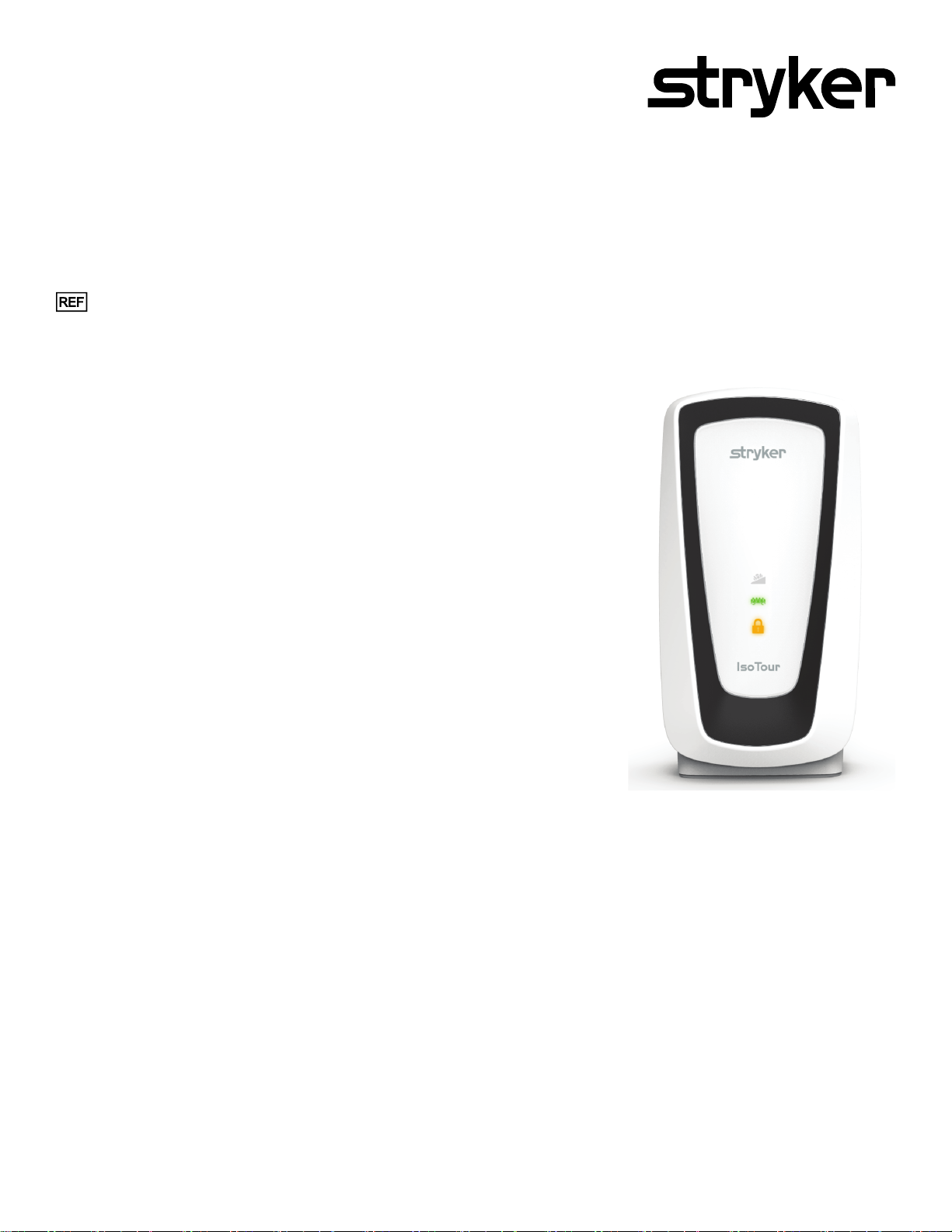
IIssooTToouurr™™ PPuummpp
MMaaiinntteennaannccee MMaannuuaall
2874
2874-009-002 Rev A.1
EN
2019/08
Page 2

Page 3
SSyymmbboollss
Refer to instruction manual/booklet
Operating instructions/Consult instructions for use
General warning
Caution
Cardiopulmonary resuscitation (CPR), disconnection point
Catalogue number
Serial number
Batch code
2797
Manufacturer
Authorized representative in the European Community
European medical device
CE mark
Mass of product
In accordance with European Directive 2012/19/EU on Waste Electrical and Electronic
Equipment (WEEE) as amended, this symbol indicates that the product should be collected
separately for recycling. Do not dispose of as unsorted municipal waste. Contact local distributor
for disposal information. Ensure infected equipment is decontaminated prior to recycling.
Indicates that this product does not contain toxic and hazardous substances or elements above
the maximum concentration of all 6 values defined by the China RoHS legislation. This product is
an environmentally friendly product which can be recycled and reused.
Class II electrical equipment: equipment in which protection against electric shock does not rely
on basic insulation only, but in which additional safety precautions such as double insulation or
reinforced insulation are provided, there being no provisions for protective earthing or reliance
upon installation conditions.
Type B applied part - 2872 IIssooTToouurr support surface
Fuse
2874-009-002 Rev A.1 EN
Page 4
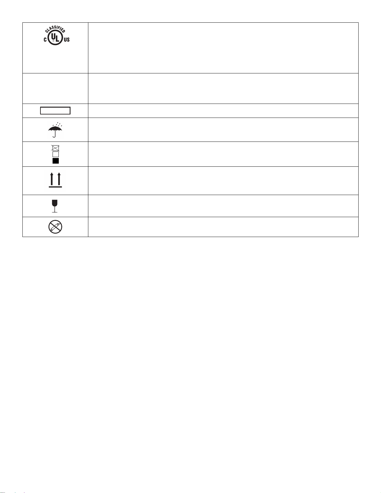
E347196
MEDICAL
ELECTRICAL
EQUIPMENT
Medical Equipment Classified by Underwriters Laboratories Inc. With Respect to Electric Shock,
6
Fire, and Mechanical Hazards Only in Accordance with ANSI/AAMI ES60601-1:2012, IEC
60601-1-8:2012, and CAN/CSA-C22.2 No. 60601-1:16.
IIPP2211
Solids: Protection from touch by fingers and objects greater than 12 mm
Liquids: Protection from the fall of vertical water drops
For US Patents see www.stryker.com/patents
Keep dry
Do not stack more than 6 high
This side up
Fragile
Do not use sharp objects to open the package
EN 2874-009-002 Rev A.1
Page 5

TTaabbllee ooff CCoonntteennttss
Warning/Caution/Note Definition ..............................................................................................................................3
Summary of safety precautions ................................................................................................................................3
Introduction ...............................................................................................................................................................4
Product description .................................................................................................................................................4
Intended use ..........................................................................................................................................................4
Expected service life ...............................................................................................................................................4
Disposal/recycle .....................................................................................................................................................4
Contraindications ....................................................................................................................................................4
Specifications .........................................................................................................................................................5
Environmental conditions ....................................................................................................................................5
Product illustration ..................................................................................................................................................6
Contact information .................................................................................................................................................6
Serial number .........................................................................................................................................................7
Date of manufacture................................................................................................................................................7
Service ......................................................................................................................................................................8
Protecting against electrostatic discharge (ESD) .......................................................................................................8
Powering off the pump.............................................................................................................................................8
Fuse replacement ...................................................................................................................................................8
Bumper replacement...............................................................................................................................................8
Foot replacement....................................................................................................................................................9
Filter replacement ...................................................................................................................................................9
LCD screen replacement .......................................................................................................................................10
Transport handle replacement ...............................................................................................................................10
Hook replacement.................................................................................................................................................11
Front pump housing replacement ........................................................................................................................... 11
Power supply replacement.....................................................................................................................................12
Power inlet replacement ........................................................................................................................................ 13
PCB assembly replacement...................................................................................................................................13
LED board replacement.........................................................................................................................................14
Solenoid/valve replacement...................................................................................................................................14
Pump replacement................................................................................................................................................15
Access diagnostic mode .........................................................................................................................................16
Preventive maintenance ......................................................................................................................................... 17
Troubleshooting ......................................................................................................................................................18
Power cords ............................................................................................................................................................19
Pump housing assembly 2874-007-017 .................................................................................................................20
Top panel assembly 2874-007-018 ........................................................................................................................21
Hook assembly 2874-007-019................................................................................................................................ 22
Bumper pack 2874-007-020 ...................................................................................................................................23
Pump housing rubber foot assembly 2874-007-022 .............................................................................................. 24
Compressor assembly 2874-007-023 .................................................................................................................... 25
Power supply assembly 2874-007-024 ..................................................................................................................26
PCBA assembly 2874-007-025 ..............................................................................................................................27
HEPA filter 2874-007-026....................................................................................................................................... 28
Air filter guard 2874-007-027 .................................................................................................................................. 29
3 way digital valve assembly 2874-007-028........................................................................................................... 30
5 way digital valve assembly 2874-007-029........................................................................................................... 31
Front LED module assembly 2874-007-030........................................................................................................... 32
Handle assembly 2874-007-031 ............................................................................................................................33
Mattress hose assembly 2874-007-034 ................................................................................................................. 34
2874-009-002 Rev A.1 1 EN
Page 6

EMC information ..................................................................................................................................................... 35
EN 2 2874-009-002 Rev A.1
Page 7

WWaarrnniinngg//CCaauuttiioonn//NNoottee DDeeffiinniittiioonn
The words WWAARRNNIINNGG, CCAAUUTTIIOONN, and NNOOTTEE carry special meanings and should be carefully reviewed.
WWAARRNNIINNGG
Alerts the reader about a situation which, if not avoided, could result in death or serious injury. It may also describe
potential serious adverse reactions and safety hazards.
CCAAUUTTIIOONN
Alerts the reader of a potentially hazardous situation which, if not avoided, may result in minor or moderate injury to the
user or patient or damage to the product or other property. This includes special care necessary for the safe and effective
use of the device and the care necessary to avoid damage to a device that may occur as a result of use or misuse.
NNoottee -- Provides special information to make maintenance easier or important instructions clearer.
SSuummmmaarryy ooff ssaaffeettyy pprreeccaauuttiioonnss
Always read and strictly follow the warnings and cautions listed on this page. Service only by qualified personnel.
WWAARRNNIINNGG
• Do not modify or change this device. Service should only be completed by qualified personnel. Failure could result in
injury and void your warranty.
• The use of accessories, transducers, and cables, other than those specified or provided by the manufacturer, could
result in increased electromagnetic emissions or decreased electromagnetic immunity and result in improper operation.
• Portable RF communications equipment, including peripherals such as antenna cables and external antennas, should
be no closer than 12 inches (30 cm) to any part of IIssooTToouurr, including cables specified by the manufacturer.
• Avoid stacking or placing equipment adjacent with other equipment to prevent improper operation of the products. If
such use is necessary, carefully observe stacked or adjacent equipment to make sure that they are operating properly.
CCAAUUTTIIOONN
• Improper usage of the product can cause injury to the patient or operator. Operate the product only as described in this
manual.
• Do not modify the product or any components of the product. Modifying the product can cause unpredictable operation
resulting in injury to patient or operator. Modifying the product also voids its warranty.
• Always use ESD protective equipment before opening antistatic bags and servicing electronic parts.
• Do not place unprotected circuit boards on the floor.
• Always use a grounded static strap to prevent static coming into contact with the PCB assembly.
2874-009-002 Rev A.1 3 EN
Page 8

IInnttrroodduuccttiioonn
This manual assists you with the operation or maintenance of your Stryker product. Read this manual before operating or
maintaining this product. Set methods and procedures to educate and train your staff on the safe operation or maintenance
of this product.
CCAAUUTTIIOONN
• Improper usage of the product can cause injury to the patient or operator. Operate the product only as described in this
manual.
• Do not modify the product or any components of the product. Modifying the product can cause unpredictable operation
resulting in injury to patient or operator. Modifying the product also voids its warranty.
NNoottee
• This manual is a permanent part of the product and should remain with the product even if the product is sold.
• Stryker continually seeks advancements in product design and quality. This manual contains the most current product
information available at the time of printing. There may be minor discrepancies between your product and this manual. If
you have any questions, contact Stryker Customer Service or Technical Support at 1-800-327-0770.
PPrroodduucctt ddeessccrriippttiioonn
The Stryker Model 2874, IIssooTToouurr™™ PPuummpp is an electric pump for use with the Stryker Model 2872, IIssooTToouurr Support
Surface. This pump provides Low Air Loss for the IIssooTToouurr standard or the premium support surface.
The pump, when connected to the premium support surface delivers the air to inflate and deflate the air bladders for the
TTrruuTTuurrnn™™ function.
IInntteennddeedd uussee
The IIssooTToouurr PPuummpp is for use with the IIssooTToouurr support surface assists in the prevention and treatment of pressure injuries
or pressure ulcers (all stages, Unstageable injury, and Deep tissue injury). We recommend you implement this product in
combination with clinical evaluation of risk factors and skin assessments made by a healthcare professional.
This pump is for use with the IIssooTToouurr support surface in an acute care setting. This may include critical care, step down,
progressive care, med/surg, sub-acute care, and post anesthesia care unit (PACU), or other locations as prescribed by a
physician. Operators of this pump include healthcare professionals (such as nurses, nurse aids, or doctors).
This product is not intended to be sterile, does not include a measuring function, and is not for use in a home healthcare
environment.
EExxppeecctteedd sseerrvviiccee lliiffee
The IIssooTToouurr PPuummpp has a 5 year expected service life under normal use, conditions, and with appropriate periodic
maintenance.
The air hose has a 2 year expected service life under normal use, conditions, and with appropriate periodic maintenance.
DDiissppoossaall//rreeccyyccllee
Always follow the current local recommendations and/or regulations governing environmental protection and the risks
associated with recycling or disposing of the equipment at the end of its useful life.
CCoonnttrraaiinnddiiccaattiioonnss
The TTrruuTTuurrnn feature is not intended for use with patients that have unstable spine.
EN 4 2874-009-002 Rev A.1
Page 9
NNoottee -- TTrruuTTuurrnn requires the IIssooTToouurr pump to be connected for use. The TTrruuTTuurrnn feature is visually identified by the icons
on the IIssooTToouurr pump (Figure 1).
FFiigguurree 11 –– TTrruuTTuurrnn iiccoonn
SSppeecciiffiiccaattiioonnss
Height 17.25 in. 43.8 cm
Width 9.25 in. 23.5 cm
Depth 7.25 in. 18.4 cm
Weight 16.3 lb 7.4 kg
Interface control panel LCD
Input voltage 100-240V
Current 0.7 Amps
Input frequency 50/60 Hz
Noise level <50 dba
Mode of operation Continuous
Power cord Short 3.2 ft 1 m
Long 16.4 ft 5 m
Compliance IEC 60601-1 3.1 Edition; RoHS Directive 2002/95/EC
Reach; IEC 60601-1-8:2012, IEC 60601-1-2:2014
Compatible with bed frame IIssooTToouurr standard and
premium support surface
with an IIssooTToouurr pump
33000022 SS33™™, 33000055 SS33™™, IInnTToouucchh™™, SSppiirriitt SSeelleecctt™™
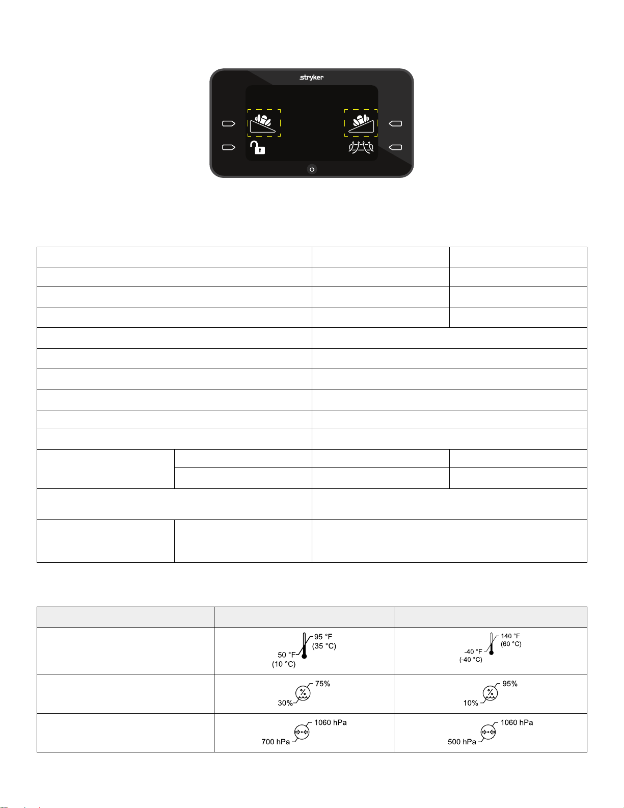
EEnnvviirroonnmmeennttaall ccoonnddiittiioonnss
EEnnvviirroonnmmeennttaall ccoonnddiittiioonnss
OOppeerraattiioonn SSttoorraaggee aanndd ttrraannssppoorrttaattiioonn
Ambient temperature
Relative humidity (non-condensing)
Atmospheric pressure
2874-009-002 Rev A.1 5 EN
Page 10
Stryker reserves the right to change specifications without notice.
C
L
I
K
A
B
C
E
F
D
G
H
J
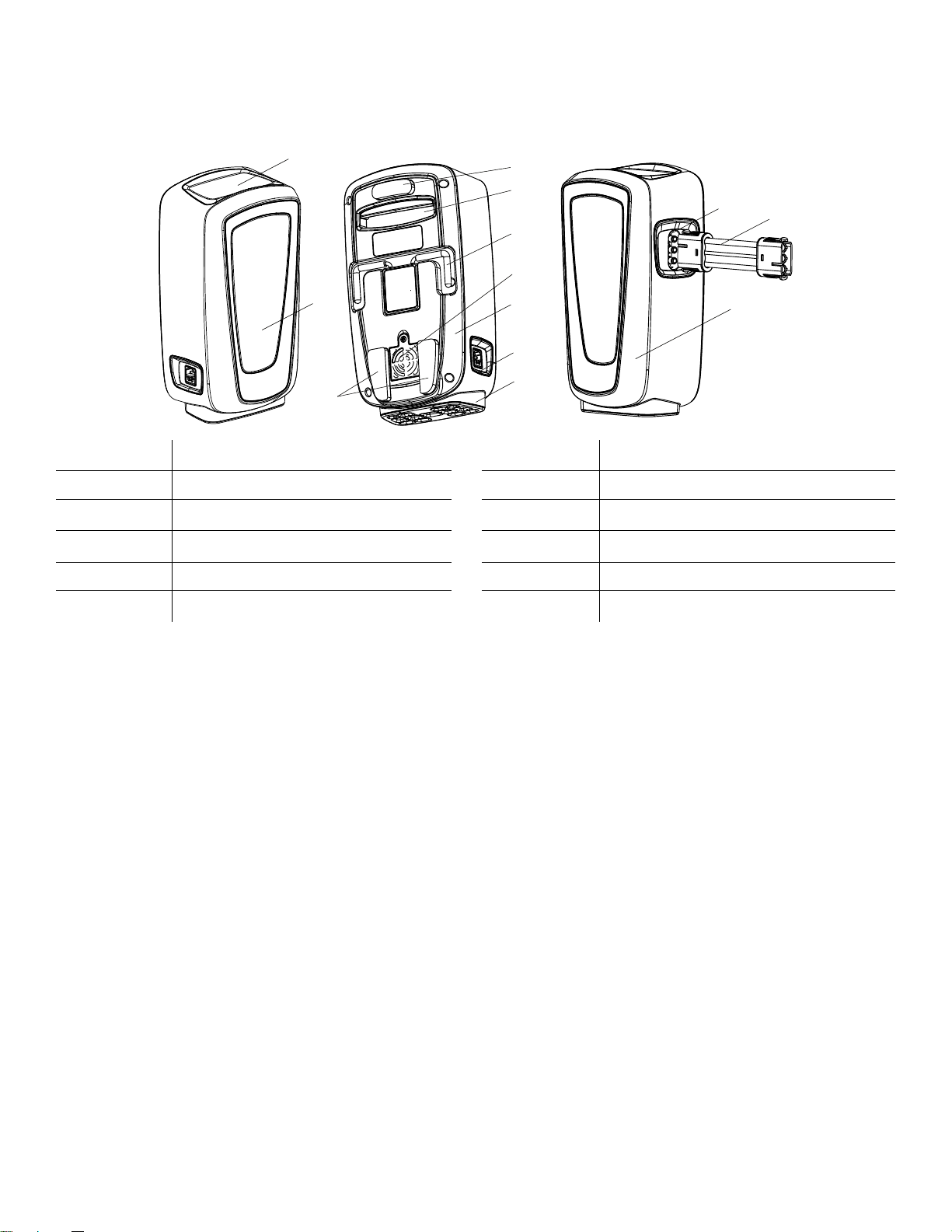
PPrroodduucctt iilllluussttrraattiioonn
A
B Status indicators H Power inlet
C
D
E Hooks K Hose
F
Graphical user interface
Bumpers
Transport handle
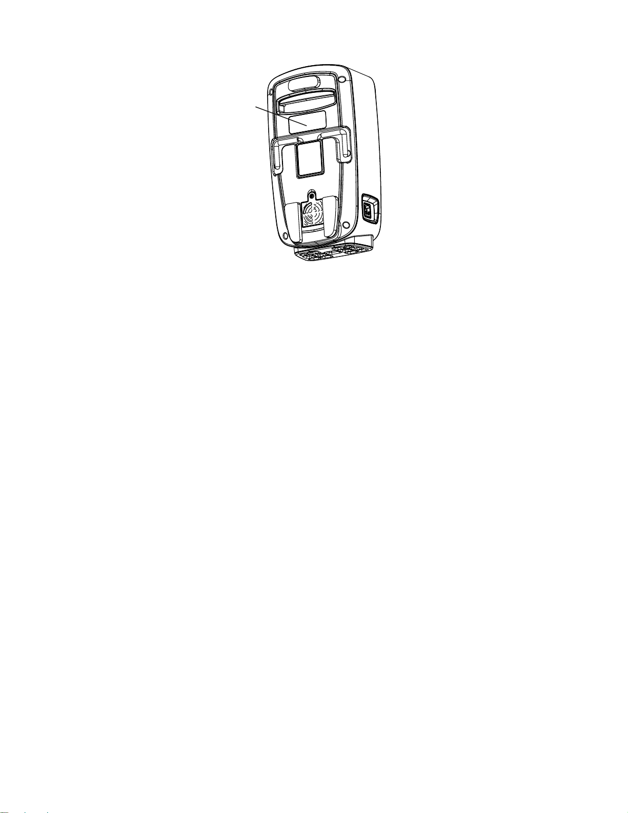
HEPA filter
G
I Anti-vibration foot
J
L
Back pump house
Hose port
Front pump housing
CCoonnttaacctt iinnffoorrmmaattiioonn
Contact Stryker Customer Service or Technical Support at: 1-800-327-0770.
Stryker Medical
3800 E. Centre Avenue
Portage, MI 49002
USA
NNoottee -- The user and/or the patient should report any serious product-related incident to both the manufacturer and the
Competent authority of the European Member State where the user and/or patient is established.
To view your operations or maintenance manual online, see https://techweb.stryker.com/.
Have the serial number (A) of your Stryker product available when calling Stryker Customer Service or Technical Support.
Include the serial number in all written communication.
EN 6 2874-009-002 Rev A.1
Page 11
SSeerriiaall nnuummbbeerr
A
DDaattee ooff mmaannuuffaaccttuurree
The year of manufacture is the first four digits of the serial number.
2874-009-002 Rev A.1 7 EN
Page 12

SSeerrvviiccee
PPrrootteeccttiinngg aaggaaiinnsstt eelleeccttrroossttaattiicc ddiisscchhaarrggee ((EESSDD))
CCAAUUTTIIOONN
• Always use ESD protective equipment before opening antistatic bags and servicing electronic parts.
• Do not place unprotected circuit boards on the floor.
NNoottee -- Always ship back circuit boards to Stryker in the same antistatic bags that the new boards were originally shipped in.
The electronic circuits in the product are completely protected from static electricity damage when factory assembled.
Always use adequate static protection when servicing the electronic systems of the product. All service personnel must use
static protection whenever they are touching wires.
Sample antistatic protection equipment includes:
• 1 antistatic wrist strap
• 1 grounding plug
• 1 test lead with a banana plug on one end and an alligator clip on the other end
Make sure that you follow the ESD manufacturer’s instructions for appropriate protection against static discharge.
PPoowweerriinngg ooffff tthhee ppuummpp
Press the power button and hold for 2 seconds to power off the pump.
NNoottee
• Allow the support surface to deflate before you unplug the power cord.
• For optional deflation, remove the CPR plug from the support surface.
FFuussee rreeppllaacceemmeenntt
Fuse rating: F2AH250V
TToooollss rreeqquuiirreedd::
• Flat head screwdriver
PPrroocceedduurree::
1. Unplug the pump from AC power.
2. Unplug the mattress tubing from the pump.
3. Place the pump front down on a work surface.
4. Using a flat head screwdriver, remove and save the fuse cover located below the power inlet.
5. Remove and dispose of the fuse.
6. Reverse the steps to reinstall.
7. Verify proper operation before you return the product to service.
BBuummppeerr rreeppllaacceemmeenntt
TToooollss rreeqquuiirreedd::
• Pick
EN 8 2874-009-002 Rev A.1
Page 13

PPrroocceedduurree::
1. Unplug the pump from AC power.
2. Unplug the mattress tubing from the pump.
3. Place the pump with the front pump housing side down on a work surface.
4. Using a pick, remove and discard the bumper from the back pump housing (
5. Place and press the bumper in place.
Bumper pack 2874-007-020
(page 23)).
FFoooott rreeppllaacceemmeenntt
TToooollss rreeqquuiirreedd::
• T20 Torx driver
• 6 mm socket
• Ratchet
PPrroocceedduurree::
1. Unplug the pump from AC power.
2. Unplug the mattress tubing from the pump.
3. Place the pump front down on a work surface.
4. Using a T20 Torx driver, remove the six screws that secure the back pump housing to the front pump housing. Save the
screws.
5. Using two hands, rotate the pump assembly to the right so the front is on your left.
6. Separate the front and back pump housing. Place the back pump housing down on the work surface.
7. Using a ratchet and a 6 mm socket, remove the six nuts that secure the foot to the front pump housing. Save the nuts.
8. Remove and discard the foot.
9. Reverse the steps to reinstall (
10.Run and pass the diagnostic test.
11.Verify proper operation before you return the product to service.
Pump housing rubber foot assembly 2874-007-022
(page 24)).
FFiilltteerr rreeppllaacceemmeenntt
TToooollss rreeqquuiirreedd::
• T20 Torx driver
PPrroocceedduurree::
1. Unplug the pump from AC power.
2. Unplug the mattress tubing from the pump.
3. Place the pump front down on a work surface.
4. Using a T20 Torx driver, remove and save the screw that secures the filter access door.
5. Remove and save the access door.
6. Remove and dispose of the filter.
7. Reverse the steps to reinstall (
8. Verify proper operation before you return the product to service.
2874-009-002 Rev A.1 9 EN
Air filter guard 2874-007-027
(page 29)).
Page 14

LLCCDD ssccrreeeenn rreeppllaacceemmeenntt
TToooollss rreeqquuiirreedd::
• T20 Torx driver
• #2 Phillips screwdriver
PPrroocceedduurree::
1. Unplug the pump from AC power.
2. Unplug the mattress tubing from the pump.
3. Place the pump front down on a work surface.
4. Using a T20 Torx driver, remove and save the six screws that secure the back pump housing to the front pump housing.
5. Using two hands, rotate the pump assembly to the right so the front is to your left.
6. Separate the front and back pump housing. Place the back pump housing down on the work surface.
7. Unplug all cables from the PCB assembly.
NNoottee -- Pay attention to the hose locations for reinstallation.
8. Using a #2 Phillips screwdriver, remove the two screws that secure the support bracket holding the PCB assembly and
the screen to the front pump housing. Save the screws.
9. Using a #2 Phillips screwdriver, remove and save the three screws that secure the board to the PCB assembly to the
screen.
10.Using a #2 Phillips screwdriver, remove and save the four screws that secure the LCD screen and gasket to the front
pump housing.
11.Remove and discard the LCD screen and gasket.
12.Reverse the steps to reinstall (
13.Run and pass the diagnostic test.
14.Verify proper operation before you return the product to service.
Top panel assembly 2874-007-018
(page 21)).
TTrraannssppoorrtt hhaannddllee rreeppllaacceemmeenntt
TToooollss rreeqquuiirreedd::
• T20 Torx driver
• #2 Phillips screwdriver
PPrroocceedduurree::
1. Unplug the pump from AC power.
2. Unplug the mattress tubing from the pump.
3. Place the pump front down on a work surface.
4. Using a T20 Torx driver, remove and save the six screws that secure the back pump housing to the front pump housing.
5. Using two hands, rotate the pump assembly to the right so the front pump housing is to your left.
6. Separate the front and back pump housing. Place the back pump housing down on the work surface.
7. Using a #2 Phillips screwdriver, remove and save the five screws that secure the back board to the back pump hosing.
8. Remove and save the back board.
9. Using a #2 Phillips screwdriver, remove and save the four screws that secure the handles to the back pump housing.
10.Remove and discard the handle.
11.Reverse the steps to reinstall (
12.Run and pass the diagnostic test.
Handle assembly 2874-007-031
(page 33)).
EN 10 2874-009-002 Rev A.1
Page 15

13.Verify proper operation before you return the product to service.
HHooookk rreeppllaacceemmeenntt
TToooollss rreeqquuiirreedd::
• T20 Torx driver
• Stubby #2 Phillips screwdriver
• Pick
PPrroocceedduurree::
1. Unplug the pump from AC power.
2. Unplug the mattress tubing from the pump.
3. Place the pump front down on a work surface.
4. Using a pick, remove and discard the information label on the hook assembly.
5. Using a #2 Phillips, remove the screw (under the label removed in step 4) that secure the hook assembly to the back
pump housing.
6. Using a T20 Torx driver, remove and save the six screws that secure the back pump housing to the front pump housing.
7. Using two hands, rotate the pump assembly to the right so the front is to your left.
8. Separate the front and back pump housing. Place the back pump housing down on the work surface.
9. Unplug the power input cable and the power output cable from the power supply.
10.Using one hand to hold the fish paper and a #2 Phillips screwdriver, remove and save the four Phillips screws and
washers that secure the power supply to the main frame.
11.Remove the power supply to the side and fish paper.
12.Using a #2 Phillips screwdriver, remove and save the four screws that secure the pump frame to the main frame and set
aside.
13.Using a #2 Phillips screwdriver remove and save the six screws that secure the hook assembly to the back pump
housing.
14.Remove and discard the hook assembly.
15.Reverse the steps to reinstall (
16.Run and pass the diagnostic test.
17.Verify proper operation before you return the product to service.
Hook assembly 2874-007-019
(page 22)).
FFrroonntt ppuummpp hhoouussiinngg rreeppllaacceemmeenntt
TToooollss rreeqquuiirreedd::
• T20 Torx driver
• #2 Phillips screwdriver
• Stubby #2 Phillips screwdriver
PPrroocceedduurree::
1. Unplug the pump from AC power.
2. Unplug the mattress tubing from the pump.
3. Place the pump front down on a work surface.
4. Using a T20 Torx driver, remove and save the six screws that secure the back pump housing to the front pump housing.
5. Using two hands, rotate the pump assembly to the right so the front is to your left.
2874-009-002 Rev A.1 11 EN
Page 16

6. Separate the front and back pump housing. Place the back pump housing down on the work surface.
CCAAUUTTIIOONN -- Always use a grounded static strap to prevent static coming into contact with the PCB assembly.
7. Unplug all cables from the PCB assembly.
NNoottee -- Pay attention to the cable connection locations for reinstallation.
8. Using a #2 Phillips screwdriver, remove the two screws that secure the support bracket holding the PCB assembly and
the screen to the front pump housing. Save the screws and support bracket.
9. Using a #2 Phillips screwdriver, remove and save the three screws that secure the board to the screen.
10.Grasp each of the air hoses individually and pull out from the mattress hose connector to detach each hose from the
connector.
NNoottee -- Pay attention to the air hose connection locations for reinstallation.
11.Grasp each of the pressure transducer hoses individually and pull out from the mattress hose connector to detach each
hose from the connector.
NNoottee -- Pay attention to the pressure transducer hose connection locations for reinstallation.
12.Using a stubby #2 Phillips screwdriver, remove the four screws that secure the LED board assembly to the front pump
housing assembly. Save the screws.
13.Remove the PCB assembly.
14.Remove and discard the front pump housing.
15.Reverse the steps to reinstall (
16.Run and pass the diagnostic test.
17.Verify proper operation before you return the product to service.
Pump housing assembly 2874-007-017
(page 20)).
PPoowweerr ssuuppppllyy rreeppllaacceemmeenntt
TToooollss rreeqquuiirreedd::
• T20 Torx driver
• #2 Phillips screwdriver
PPrroocceedduurree::
1. Unplug the pump from AC power.
2. Unplug the mattress tubing from the pump.
3. Place the pump front down on a work surface.
4. Using a T20 Torx driver, remove and save the six screws that secure the back pump housing to the front pump housing.
5. Using two hands, rotate the pump assembly to the right so the front is to your left.
6. Separate the front and back pump housing. Place the back pump housing down on the work surface.
7. Grasp the hose at the manifold coming from the pump and pull to remove the hose from the manifold.
8. Unplug the power input cable and the power output cable from the power supply.
9. Using one hand to hold the fish paper and a #2 Phillips screwdriver, remove the four Phillips screws and washers that
secure the power supply to the main frame. Save the screws, washers, and fish paper.
10.Remove and discard the power supply.
11.Reverse the steps to reinstall (
12.Run and pass the diagnostic test.
13.Verify proper operation before you return the product to service.
Power supply assembly 2874-007-024
(page 26)).
EN 12 2874-009-002 Rev A.1
Page 17

PPoowweerr iinnlleett rreeppllaacceemmeenntt
TToooollss rreeqquuiirreedd::
• T20 Torx driver
• Flat blade screwdriver
PPrroocceedduurree::
1. Unplug the pump from AC power.
2. Unplug the mattress tubing from the pump.
3. Place the pump front down on a work surface.
4. Using a T20 Torx driver, remove and save the six screws that secure the back pump housing to the front pump housing.
5. Using two hands, rotate the pump assembly to the right so the front is to your left.
6. Separate the front and back pump housing. Place the back pump housing down on the work surface.
7. Unplug the power inlet from the power supply.
8. Using a flat blade screwdriver and your finger, push out on the power inlet while you push in on each of the power inlet
locks to loosen the power inlet from the front pump housing. Repeat on the other side to remove.
9. Remove and discard the power inlet.
10.Reverse the steps to reinstall (
11.Run and pass the diagnostic test.
12.Verify proper operation before you return the product to service.
Pump housing assembly 2874-007-017
(page 20)).
PPCCBB aasssseemmbbllyy rreeppllaacceemmeenntt
TToooollss rreeqquuiirreedd::
• T20 Torx driver
• #2 Phillips screwdriver
• ESD
PPrroocceedduurree::
1. Unplug the pump from AC power.
2. Unplug the mattress tubing from the pump.
3. Place the pump front down on a work surface.
4. Using a T20 Torx driver, remove and save the six screws that secure the back pump housing to the front pump housing.
5. Using two hands, rotate the pump assembly to the right so the front is to your left.
6. Separate the front and back pump housing. Place the back pump housing down on the work surface.
CCAAUUTTIIOONN -- Always use a grounded static strap to prevent static coming into contact with the PCB assembly.
7. Unplug all cables from the PCB assembly.
NNoottee -- Pay attention to the cable connection locations for reinstallation.
8. Grasp each of the pressure transducer hoses individually and pull out from the PCB assembly to detach each hose from
the PCB assembly.
NNoottee -- Pay attention to the pressure transducer hose connection locations for reinstallation.
9. Using a #2 Phillips screwdriver, remove the two screws that secure the support bracket that hold the PCB assembly and
the screen to the front pump housing. Save the screws and support bracket.
10.Using a #2 Phillips screwdriver, remove and save the three screws that secure the board to the screen.
2874-009-002 Rev A.1 13 EN
Page 18

11.Remove and discard the PCB assembly.
12.Reverse the steps to reinstall (
13.Run and pass the diagnostic test.
14.Verify proper operation before you return the product to service.
PCBA assembly 2874-007-025
(page 27)).
LLEEDD bbooaarrdd rreeppllaacceemmeenntt
TToooollss rreeqquuiirreedd::
• T20 Torx driver
• Stubby #2 Phillips screwdriver
•
Protecting against electrostatic discharge (ESD)
PPrroocceedduurree::
1. Unplug the pump from AC power.
2. Unplug the mattress tubing from the pump.
3. Place the pump front down on a work surface.
4. Using a T20 Torx driver, remove and save the six screws that secure the back pump housing to the front pump housing.
5. Using two hands, rotate the pump assembly to the right so the front is to your left.
6. Separate the front and back pump housing. Place the back pump housing down on the work surface.
(page 8)
CCAAUUTTIIOONN -- Always use a grounded static strap to prevent static coming into contact with the PCB assembly.
7. Unplug the LED board cable from the PCB assembly.
NNoottee -- Pay attention to the cable connection locations for reinstallation.
8. Using a stubby #2 Phillips screwdriver, remove and save the four screws that secure the LED board assembly to the
front pump housing assembly.
9. Unplug and save the cable from the LED board assembly.
10.Remove and discard the LED board assembly.
11.Reverse the steps to reinstall (
12.Run and pass the diagnostic test.
13.Verify proper operation before you return the product to service.
Front LED module assembly 2874-007-030
(page 32)).
SSoolleennooiidd//vvaallvvee rreeppllaacceemmeenntt
TToooollss rreeqquuiirreedd::
• T20 Torx driver
• #2 Phillips screwdriver
• 2.5 mm hex wrench
PPrroocceedduurree::
1. Unplug the pump from AC power.
2. Unplug the mattress tubing from the pump.
3. Place the pump front down on a work surface.
4. Using a T20 Torx driver, remove and save the six screws that secure the back pump housing to the front pump housing.
5. Using two hands, rotate the pump assembly to the right so the front is to your left.
EN 14 2874-009-002 Rev A.1
Page 19

6. Separate the front and back pump housing. Place the back pump housing down on the work surface.
7. On the solenoid/valve that needs to be replaced, make note of the hose locations first, then unplug each hose from the
valve.
NNoottee -- Pay attention to the hose locations for reinstallation.
8. Unplug the solenoid cable from the PCB.
9. Using a #2 Phillips screwdriver, remove and save the two screws that secure the valve to the valve bracket.
10.Remove and discard the solenoid/valve.
11.Reverse the steps to reinstall (
2874-007-029
12.Run and pass the diagnostic test.
13.Verify proper operation before you return the product to service.
(page 31)).
3 way digital valve assembly 2874-007-028
(page 30) or
5 way digital valve assembly
PPuummpp rreeppllaacceemmeenntt
TToooollss rreeqquuiirreedd::
• T20 Torx driver
• Wire cutters
• #2 Phillips screwdriver
PPrroocceedduurree::
1. Unplug the pump from AC power.
2. Unplug the mattress tubing from the pump.
3. Place the pump front down on a work surface.
4. Using a T20 Torx driver, remove and save the six screws that secure the back pump housing to the front pump housing.
5. Using two hands, rotate the pump assembly to the right so the front is to your left.
6. Separate the front and back pump housing. Place the back pump housing down on the work surface.
7. Grasp the hose at the manifold coming from the pump and pull to remove the hose from the manifold.
8. Using wire cutters, cut the four zip ties that secure the pump power cable to the rest of the cables.
CCAAUUTTIIOONN -- Always use a grounded static strap to prevent static coming into contact with the PCB assembly.
NNoottee
• Use care when you cut the zip ties that you do not cut or damage the cables.
• Replace the zip ties when you reinstall.
9. Unplug the pump power cable from the PCB assembly.
10.Using a #2 Phillips screwdriver, remove and save the screw that secures the pump cable p-clamp to the main frame.
Remove and save the p-clamp.
11.Using a T20 Torx driver, remove and save the four screws that secure the pump frame to the main frame.
12.Remove the spring from the hose and insert into the new pump assembly hose.
13.Remove and discard the pump assembly.
14.Reverse the steps to reinstall (
15.Run and pass the diagnostic test.
16.Verify proper operation before you return the product to service.
2874-009-002 Rev A.1 15 EN
Compressor assembly 2874-007-023
(page 25)).
Page 20

AAcccceessss ddiiaaggnnoossttiicc mmooddee
IsoTour
V vx.x.x.xxx
PPrroocceedduurree::
1. Make sure that the support surface hoses are plugged into the pump and there is no weight on the support surface.
2. Power on the pump.
3. As the software loads, within 5 seconds of pressing the on button (Figure 2), press and hold the upper left button (Figure
3).
FFiigguurree 22 –– SSooffttwwaarree llooaaddiinngg
4. Press the lower left button to start the diagnostics mode.
NNoottee -- The software version is located on the service screen (Figure 3).
5. The diagnostic results should all pass with OK.
a. If diagnostic results do not pass, investigate failed area referenced in the diagnostic test results.
FFiigguurree 33 –– SSeerrvviiccee ssccrreeeenn aanndd vveerrssiioonn
EN 16 2874-009-002 Rev A.1
Page 21

PPrreevveennttiivvee mmaaiinntteennaannccee
WWAARRNNIINNGG -- Do not modify or change this device. Service should only be completed by qualified personnel. Failure could
result in injury and void your warranty.
NNoottee
• At a minimum, check all items listed during annual preventive maintenance for all Stryker Medical products. You may
need to perform preventive maintenance checks more often based on your level of product usage.
• Remove product from service before you perform preventive maintenance.
• Consult your local regulations to dispose of electronic equipment.
Inspect the following items:
All fasteners are secure
Pump housing or components (hoses, power cords, or case) for cracks, holes, or damaged
Hooks that hang the pump on the bed frame are not damaged
No air leaks from the pump or the attached connectors or hoses
Graphical user interface is not cracked or damaged
HEPA filter (replace each year)
Fuse
All functions on graphical user interface operate
Run diagnostic test (All okay)
Product serial number:
Completed by:
Date:
2874-009-002 Rev A.1 17 EN
Page 22

TTrroouubblleesshhoooottiinngg
29:59
PPrroobblleemm SSccrreeeenn CCaauussee RReeccoommmmeennddeedd aaccttiioonn
Kinked air hoses
Missed connection with air
hoses
Air hose is bent or an
obstruction in the hose may
cause air flow to be
compromised
TTrruuTTuurrnn was attempted but
you have a standard model
(bottom cover is orange)
Air hoses is not connected
to the pump or the support
surface
1. Make sure that the hoses
are straight and air flow is
not obstructed.
2. Press the action button
next to the Alarm off icon
to reset the pump.
Contact sales support for
TTrruuTTuurrnn option
1. Make sure that the hoses
are seated all the way
onto the hose ports on
the pump or the support
surface.
2. Press the action button
next to the Alarm off icon
to reset the pump.
Power loss, product does
not turn on
Power loss, while TTrruuTTuurrnn
is in use
Button not responsive
TTrruuTTuurrnn not shown on
screen
TTrruuTTuurrnn shown on screen
Power cord not seated,
power cord unplugged from
outlet, or possible internal
damage, Button is stuck.
Unintentional or intentional
power loss.
Lock function active. Button
is stuck.
Kinked hose during setup.
IIssooTToouurr standard model is
connected.
Graphical user interface
shows TTrruuTTuurrnn but you
have a standard model
(bottom cover is orange)
Make sure that the power
cord is plugged into the
product and the outlet.
Replace the LCD screen.
Pull the hose from the pump
or the support surface to
activate CPR. The bladder
deflates and returns the
support surface to a flat
position.
Press and hold the action
button next to the locked icon
for 2 seconds to turn off the
lock. Replace the LCD
screen. Power cycle the
pump.
Check for kinked hoses.
Verify that you have premium
bottom cover (black).
Contact sales support for
TTrruuTTuurrnn option.
Turn off the pump to reset
the pump features. Make
sure that the air hose is
connected before you turn
the pump on.
EN 18 2874-009-002 Rev A.1
Page 23

PPoowweerr ccoorrddss
PPaarrtt NNuummbbeerr
Power cord, type B, 1 meter 2874-007-001
Power cord, type B, 5 meter 2874-007-002
Power cord, type E/F, 1 meter 2874-007-003
Power cord, type E/F, 5 meter 2874-007-004
Power cord, type J, 1 meter 2874-007-007
Power cord, type J, 5 meter 2874-007-008
Power cord, type I, 1 meter 2874-007-009
Power cord, type I, 5 meter 2874-007-010
Power cord, type G, 1 meter 2874-007-011
Power cord, type G, 5 meter 2874-007-012
Power cord, type L, 1 meter 2874-007-013
Power cord, type L, 5 meter 2874-007-014
Power cord, type N, 1 meter 2874-007-015
Power cord, type N, 5 meter 2874-007-016
2874-009-002 Rev A.1 19 EN
Page 24

PPuummpp hhoouussiinngg aasssseemmbbllyy 22887744--000077--001177
EN 20 2874-009-002 Rev A.1
Page 25

TToopp ppaanneell aasssseemmbbllyy 22887744--000077--001188
A
C
B
D
IItteemm NNuummbbeerr NNaammee QQuuaannttiittyy
A 517M064022 Gasket 1
B Reference only Top panel subassembly 1
C 521096S05 Screws 3
D 521M064051 Screws 4
2874-009-002 Rev A.1 21 EN
Page 26

HHooookk aasssseemmbbllyy 22887744--000077--001199
A
C
B
D
E
F
H
G
G
IItteemm NNuummbbeerr NNaammee QQuuaannttiittyy
A 515M064013 Hook 2
B 515M064014 Hook stopper 2
C 511M064104 Hook clutch gear A 2
D 511M064105 Hook clutch gear B 2
E 523M064001 Hook spring 2
F 511M104016 Hook back cover 1
G 521M064005 Internal screws 7
H 622M104003 Hook, back cover label 1
EN 22 2874-009-002 Rev A.1
Page 27

BBuummppeerr ppaacckk 22887744--000077--002200
A
C
B
IItteemm NNuummbbeerr NNaammee QQuuaannttiittyy
A 517M104004 Bumper left bottom 1
B 517M104005 Bumper right bottom 1
C 517M104006 Bumper top 1
2874-009-002 Rev A.1 23 EN
Page 28

PPuummpp hhoouussiinngg rruubbbbeerr ffoooott aasssseemmbbllyy 22887744--000077--002222
A
B
IItteemm NNuummbbeerr NNaammee QQuuaannttiittyy
A 517M104001 Molded rubber foot 1
B 521096N01 Nut fasteners 6
EN 24 2874-009-002 Rev A.1
Page 29

CCoommpprreessssoorr aasssseemmbbllyy 22887744--000077--002233
IItteemm NNuummbbeerr NNaammee QQuuaannttiittyy
A Compressor subassembly 1
B 521M064026 Screws 4
C 511M092013 Nylon wire tie (not shown) 6
2874-009-002 Rev A.1 25 EN
Page 30

PPoowweerr ssuuppppllyy aasssseemmbbllyy 22887744--000077--002244
A
C
B
D
IItteemm NNuummbbeerr NNaammee QQuuaannttiittyy
A 553M104003 Power supply 1
B 521M064024 Isolation paper 1
C 521096B07 Mounting screws 4
D 521M064050 Screw gasket 8
E 555M064028 Cable (not shown) 1
F 511M092013 Cable nylon tie (not shown) 4
EN 26 2874-009-002 Rev A.1
Page 31

PPCCBBAA aasssseemmbbllyy 22887744--000077--002255
A
C
B
IItteemm NNuummbbeerr NNaammee QQuuaannttiittyy
A Reference only PCBA subassembly 1
B 521096505 Screws 3
C 511M104013 Molded PCB holder 1
2874-009-002 Rev A.1 27 EN
Page 32

HHEEPPAA ffiilltteerr 22887744--000077--002266
A
IItteemm NNuummbbeerr NNaammee QQuuaannttiittyy
A 517M104015 HEPA filter 1
EN 28 2874-009-002 Rev A.1
Page 33

AAiirr ffiilltteerr gguuaarrdd 22887744--000077--002277
A
B
IItteemm NNuummbbeerr NNaammee QQuuaannttiittyy
A 511M104015 Molded air filter guard 1
B 521M064029 Screw 1
2874-009-002 Rev A.1 29 EN
Page 34

33 wwaayy ddiiggiittaall vvaallvvee aasssseemmbbllyy 22887744--000077--002288
B
A
C
IItteemm NNuummbbeerr NNaammee QQuuaannttiittyy
A Reference only 3 way digital valve subassembly 1
B 521M064025 Screws 2
C 521M064026 Screws 4
EN 30 2874-009-002 Rev A.1
Page 35

55 wwaayy ddiiggiittaall vvaallvvee aasssseemmbbllyy 22887744--000077--002299
A
C
B
IItteemm NNuummbbeerr NNaammee QQuuaannttiittyy
A Reference only 5 way digital valve subassembly 1
B 521M064025 Screws 2
C 521M064026 Screws 4
2874-009-002 Rev A.1 31 EN
Page 36

FFrroonntt LLEEDD mmoodduullee aasssseemmbbllyy 22887744--000077--003300
A
B
IItteemm NNuummbbeerr NNaammee QQuuaannttiittyy
A Reference only Front LED PCB subassembly 1
B 521M064051 Screws 4
EN 32 2874-009-002 Rev A.1
Page 37

HHaannddllee aasssseemmbbllyy 22887744--000077--003311
A
B
IItteemm NNuummbbeerr NNaammee QQuuaannttiittyy
A 511M104017 Molded handle 1
B 521M064005 Screws 4
2874-009-002 Rev A.1 33 EN
Page 38

MMaattttrreessss hhoossee aasssseemmbbllyy 22887744--000077--003344
518M104001
EN 34 2874-009-002 Rev A.1
Page 39

EEMMCC iinnffoorrmmaattiioonn
WWAARRNNIINNGG -- The use of accessories, transducers, and cables, other than those specified or provided by the manufacturer,
could result in increased electromagnetic emissions or decreased electromagnetic immunity and result in improper
operation.
NNoottee
• The emissions characteristics of this equipment make it suitable for use in industrial areas and hospitals (CISPR 11
class A). If it is used in a residential environment (for which CISPR 11 class B is normally required) this equipment might
not offer adequate protection to radio-frequency communication services. The user might need to take mitigation
measures, such as relocating or re-orienting the equipment.
• This equipment is suitable for use in hospitals except for near active HF surgical equipment and the RF shielded room of
an ME system for magnetic resonance imaging, where the intensity of EM disturbances is high.
GGuuiiddaannccee aanndd mmaannuuffaaccttuurreerr’’ss ddeeccllaarraattiioonn -- eelleeccttrroommaaggnneettiicc eemmiissssiioonnss
The 2874 IIssooTToouurr pump is intended for use in the electromagnetic environment specified below. The customer or the
user of the 2874 IIssooTToouurr pump should assure that it is used in such an environment.
EEmmiissssiioonnss tteesstt
RF Emissions
CISPR 11
RF Emissions
CISPR 11
Harmonic Emissions
IEC 61000-3-2
Voltage Fluctuations
Flicker Emissions
IEC 61000-3-3
WWAARRNNIINNGG
• Portable RF communications equipment, including peripherals such as antenna cables and external antennas, should
be no closer than 12 inches (30 cm) to any part of IIssooTToouurr, including cables specified by the manufacturer.
• Avoid stacking or placing equipment adjacent with other equipment to prevent improper operation of the products. If
such use is necessary, carefully observe stacked or adjacent equipment to make sure that they are operating properly.
CCoommpplliiaannccee EElleeccttrroommaaggnneettiicc eennvviirroonnmmeenntt
The 2874 IIssooTToouurr pump uses RF energy only for its
Group 1
Class A
Class A
Complies
internal function. Therefore, its RF emissions are
very low and are not likely to cause any interference
in nearby electronic equipment.
The 2874 IIssooTToouurr pump is suitable for use in all
establishments other than domestic and those
directly connected to the public low voltage power
supply network that supplies buildings used for
domestic purposes.
RReeccoommmmeennddeedd sseeppaarraattiioonnss ddiissttaanncceess bbeettwweeeenn ppoorrttaabbllee aanndd mmoobbiillee RRFF ccoommmmuunniiccaattiioonn eeqquuiippmmeenntt aanndd tthhee 22887744
IIssooTToouurr ppuummpp
The 2874 IIssooTToouurr pump is intended for use in an electromagnetic environment in which radiated RF disturbances are
controlled. The customer or the user of the 2874 IIssooTToouurr pump can help prevent electromagnetic interferences by
maintaining a minimum distance between portable and mobile RF communications equipment (transmitters) and the
2874 IIssooTToouurr pump as recommended below, according to the maximum output power of the communications
equipment.
BBaanndd ((MMHHzz))
2874-009-002 Rev A.1 35 EN
SSeerrvviiccee
MMaaxxiimmuumm PPoowweerr
((WW))
MMiinniimmuumm SSeeppaarraattiioonn DDiissttaannccee
((mm))
Page 40

RReeccoommmmeennddeedd sseeppaarraattiioonnss ddiissttaanncceess bbeettwweeeenn ppoorrttaabbllee aanndd mmoobbiillee RRFF ccoommmmuunniiccaattiioonn eeqquuiippmmeenntt aanndd tthhee 22887744
IIssooTToouurr ppuummpp
380-390 TETRA 400 1.8 0.3
430-470
704-787
800-960
1,700-1,990
2,400-2,570
5,100-5,800
For transmitters rated at a maximum output power not listed above, the recommended separation distance
(m) can be estimated using the equation applicable to the frequency of the transmitter, where
power rating of the transmitter in watts (W) according to the transmitter manufacturer.
GMRS 460;
FRS 460
LTE Band 13, 17
GSM 800/900;
TETRA 800;
iDEN 820;
CDMA 850;
LTE Band 5
GSM 1800;
CDMA 1900;
GSM 1900;
DECT;
LTE Band 1, 3, 4, 25;
UMTS
Bluetooth;
WLAN;
802.11 b/g/n;
RFID 2450;
LTE Band 7
WLAN 802.11 a/n 0.2 0.3
2.0 0.3
0.2 0.3
2.0 0.3
2.0 0.3
2.0 0.3
P
is the maximum output
d
in meters
NNoottee -- These guidelines may not apply in all situations. Electromagnetic propagation is affected by absorption and
reflection from structures, objects and people.
GGuuiiddaannccee aanndd mmaannuuffaaccttuurreerr’’ss ddeeccllaarraattiioonn -- eelleeccttrroommaaggnneettiicc iimmmmuunniittyy
The 2874 IIssooTToouurr pump is suitable for use in the electromagnetic environment specified below. The customer or the
user of the 2874 IIssooTToouurr pump should assure that it is used in such an environment.
IImmmmuunniittyy tteesstt
Electrostatic Discharge
(ESD)
IEC 61000-4-2
Electrostatic fast transient/
burst
IEC 61000-4-4
IIEECC 6600660011 tteesstt lleevveell
+8 kV contact
+15 kV air
+2 kV for power supply lines
+1 kV for input/ output lines
CCoommpplliiaannccee lleevveell
+8 kV contact
+15 kV air
+2 kV for power supply lines
+1 kV for input/ output lines
EElleeccttrroommaaggnneettiicc
eennvviirroonnmmeenntt--gguuiiddaannccee
Floors should be wood,
concrete, or ceramic tile. If
floors are covered with
synthetic material, the
relative humidity should be
at least 30%.
Main power quality should
be that of a typical
commercial or hospital
environment.
Surge
±1 kV for input/output lines ±1 kV for input/output lines
IEC 61000-4-5
EN 36 2874-009-002 Rev A.1
Main power quality should
be that of a typical
commercial or hospital
environment.
Page 41

GGuuiiddaannccee aanndd mmaannuuffaaccttuurreerr’’ss ddeeccllaarraattiioonn -- eelleeccttrroommaaggnneettiicc iimmmmuunniittyy
Voltage dips, voltage
variations and short
interruptions on power
supply input lines
IEC 61000-4-11
Power frequency (50/60 Hz)
magnetic field
IEC 61000-4-8
0%U
for 0.5 cycle at 0°,
T
45°, 90°, 135°, 180°, 225°,
270°, and 315°
0%U
for 1 cycle
T
70%U
(30% dip in UT) for
T
25/30 cycles
0% U
for 250/300 cycles
T
30 A/m 30 A/m
for 0.5 cycle at 0°,
0%U
T
45°, 90°, 135°, 180°, 225°,
270°, and 315°
0%U
for 1 cycle
T
70%U
(30% dip in UT) for
T
25/30 cycles
0% U
for 250/300 cycles
T
Main power quality should
be that of a typical
commercial or hospital
environment. If the user of
the 2874 IIssooTToouurr pump
requires continued
operation during power
main interruptions, it is
recommended that the
device be powered from an
uninterrupted power supply
or a battery.
Power frequency magnetic
fields should be at levels
characteristic of a typical
location in a typical
commercial or hospital
environment.
NNoottee -- U
is the a.c. mains voltage before applications of the test level.
T
2874-009-002 Rev A.1 37 EN
Page 42

Conducted RF
IEC 61000- 4-6
Radiated RF
IEC 61000-4-3
3 Vrms
150 kHz to 80 MHz
3 V/m
80 MHz to 2.7 GHz
3 Vrms
3 V/m
Portable and mobile RF
communications equipment
should be used no closer to
any part of the 2874
IIssooTToouurr pump, including
cables, than the
recommended separation
distance calculated from the
equation appropriate for the
frequency of the transmitter.
Recommended separation
distance
P
D=(1.2) (√
)
80 MHz to 800 MHz
P
D=(2.3) (√
)
800 MHz to 2.7 GHz
where
P
is the maximum
output power rating of the
transmitter in watts (W)
according to the transmitter
manufacturer and
d
is the
recommended separation
distance in meters (m).
Field strengths from fixed
RF transmitters, as
determined by an
electromagnetic site
a
survey
, should be less than
the compliance level in each
frequency range
b
.
Interference may occur in
the vicinity of equipment
marked with the following
symbol:
NNoottee
• At 80 MHz and 800 MHz, the higher frequency range applies.
• These guidelines may not apply in all situations. Electromagnetic propagation is affected by absorption and reflection
from structures, objects and people.
• The ISM (Industrial, Scientific, and Medical) bands between 0.15 MHz and 80 MHz are 6.765 MHz to 6.795 MHz;
13.553 MHz to 13.567 MHz; 26.957 MHz to 27.283 MHz; and 40.66 MHz to 40.70 MHz.
a
Field strengths from fixed transmitters, such as base stations for radio (cellular/cordless) telephones and land mobile
radios, amateur radio, AM and FM radio broadcast, and TV broadcast cannot be predicted theoretically with accuracy. To
assess the electromagnetic environment due to fixed RF transmitters, an electromagnetic site survey should be
considered. If the measured field strength in the location in which the 2874 IIssooTToouurr pump is used exceeds the applicable
RF compliance level above, the 2874 IIssooTToouurr pump should be observed to verify normal operation. If abnormal
performance is observed, additional measures may be necessary, such as reorienting or relocating the 2874 IIssooTToouurr
pump.
b
Over the frequency range 150 kHz to 80 MHz, field strengths are less than 3 Vrms.
EN 38 2874-009-002 Rev A.1
Page 43

Page 44

Stryker Medical
3800 E. Centre Avenue
Portage, MI 49002
USA
2874-009-002 Rev A.1
WCR: AA.21
2019/08
 Loading...