

Page 1
Original instructions
Electric forklift truck
RX50-10
RX50-13
RX50-15
RX50-16
5060 5061 5063 5065 5066
55048011501 EN - 02/2018
Page 2

Page 3

Preface
Address of manufacturer and contact details
STILL GmbH
Berzeliusstraße 10
22113 Hamburg, Germany
Tel. +49 (0) 40 7339-0
Fax: +49 (0) 40 7339-1622
Email: info@still.de
Website: http://www.still.de
Rules for the operating company of industrial trucks
In addition to these operating instructions,
a code of practice containing additional
information for the operating companies of
industrial trucks is also available.
This guide provides information for handling
industrial trucks:
• Information on how to select suitable
industrial trucks for a particular area of
application
• Prerequisites for
industrial trucks
• Information on the use of industrialtrucks
• Information on transport, initial commissioning and storage of industrial trucks
thesafeoperationof
g
Internet address and QR code
The information c
by pasting the add
in a web browser or
an be accessed at any time
ress https://m.still.de/vdma
by scanning the QR code.
48011501 EN - 02/2018 I
550
Page 4

Page 5

Table of contents
1 Foreword
Your truck .......................................................... 2
Descriptionofthetruck ................................................. 2
General ............................................................ 4
CElabelling ......................................................... 5
EC declaration of conformit
Accessories ......................................................... 6
Overview ........................................................... 8
Nameplate .......................................................... 9
Production number . . . ............................................... 10
StVZO(RoadTrafficLicensingRegulations)information ....................... 10
Use of truck ........................................................ 10
Commissioning ..................................................... 10
Proper usage ....................................................... 11
Proper use during towing .............................................. 1
Impermissibleuse ................................................... 12
Placeofuse ........................................................ 12
Parking in temperatures
Usingworkingplatforms ............................................... 14
Information about documentation ........................................ 15
Documentationscope ................................................ 15
Supplementarydocumentation .......................................... 16
Issuedateandtopicalityoftheoperatinginstructions .......................... 17
Copyright and tradema
Explanation of information symbols used . . ................................ 17
Listofabbreviations .................................................. 18
Definition of directi
Schematicviews .................................................... 20
Environmental considerations .......................................... 22
Packaging ......................................................... 22
Disposal of components and batteries ..................................... 22
ons ................................................ 20
y in accordance with Machinery Directive ............... 6
below-10°C ..................................... 13
rkrights .......................................... 17
g
1
2Safety
Definition of responsible persons ........................................ 24
Operatingcompany .................................................. 2
Specialist .......................................................... 24
Drivers ........................................................... 25
Essentials for saf
Insurance cover on company premises .................................... 27
Changes and retrofitting ............................................... 27
e operation ........................................... 27
48011501 EN - 02/2018 III
550
4
Page 6

Table of contents
g
Changes to the overhead guard and roof loads . . . ........................... 30
Warning regarding non-original parts ..................................... 30
Damage, defects and misuse of s
Tyres ............................................................. 31
Medicalequipment ................................................... 32
Exercise caution when handlin
Lengthoftheforkarms ................................................ 33
Residual risk ....................................................... 35
Residual dangers, residual
Specialrisksassociatedwithusingthetruckandattachments ................... 36
Overview of hazards and countermeasures ................................. 38
Danger to employees ................................................. 41
Safety tests ........................................................ 42
Regularsafetyinspectionofthetruck ..................................... 42
Insulationtesting .................................................... 42
Safety regulations for handling consumables ............................... 44
Permissibleconsumables ............................................. 44
Oils .............................................................. 44
Hydraulicfluid ...................................................... 45
Batteryacid ........................................................ 46
Brakefluid ......................................................... 47
Disposalofconsumables .............................................. 49
Emissions ......................................................... 50
afetysystems .............................. 31
ggasspringsandaccumulators .................. 33
risks ......................................... 35
3Overviews
Full view .......................................................... 54
General view of driver's compartment ..................................... 56
Shelf and cup holder ................................................. 57
Operating devices
Display operating unit ................................................. 58
Operatingdevicesforhydraulicandtractionfunctions ......................... 59
Multi-lever ......................................................... 60
Doublemini-lever .................................................... 61
Three-waymini-lever ................................................. 62
Four-waymini-lever .................................................. 63
Joystick4Plus ...................................................... 64
Fingertip .......................................................... 65
Miniconsole ....................................................... 66
IV 5
and display elements ................................... 58
5048011501 EN - 02/2018
Page 7

Table of contents
4 Operation
Checks and tasks before daily use ....................................... 68
Visual inspections and functi
Climbingon/off ...................................................... 71
AdjustingtheMSG65/MSG75driver'sseat ................................ 72
Seatbelt .......................................................... 76
Adjustingthearmrest ................................................. 79
Unlockingtheemergencyoffswitch ...................................... 80
Switchingonthekeyswitch ............................................ 8
AccessauthorisationwithPINcode(variant) ................................ 84
Operating the signal horn .............................................. 94
Checking the brake system f
Checkingthesteeringsystemforcorrectfunction ............................ 96
Checking the emergency stop function .................................... 97
Checking the vertical lif
Zeroadjustmentoftheloadmeasurement(variant) ........................... 98
Checking the condition of the wheels and tyres ..............................100
Display-operating unit
Indicators .........................................................101
Adjustingthedisplays ................................................103
Symbolsinthedisplay ................................................1
Settingthedateortime ................................................110
Resetting the daily kilometres and daily operating hours .......................110
Setting the language . . ...............................................11
Softkeys for operating various equipment variants ............................111
Blue-Q efficiency mode ...............................................113
Functional descriptio
Switching off additional consumers .......................................114
SwitchingefficiencymodeBlue-Qonandoff ................................114
Configuring Blue-Q effic
Driving ............................................................117
Safety regulations when driving .........................................117
Driveways ....................................................... . . 119
Settingthedriveprograms .............................................122
Special overhead guard for drive-in racks (variant) ...........................122
Selecting the drive d
Actuatingthedrivedirectionswitch,multiple-leverversion ......................125
Actuatingthedrivedirectionswitch,mini-leverversion .........................125
Actuating the vertica
Actuatethedrivedirectionswitch,fingertipversion ...........................126
Actuatingthedrivedirectionswitch,mini-consoleversion ......................127
onchecking .................................. 68
orcorrectfunction .............................. 95
tmastposition(variant)forcorrectfunction ................ 98
................................................101
n ................................................113
iencymode ......................................115
irection ............................................124
l rocker switch for the "drive direction", joystick 4Plus version . . . . 126
g
1
05
1
48011501 EN - 02/2018 V
550
Page 8

Table of contents
g
Startingdrivemode ..................................................127
Starting drive mode, dual-pedal version (variant) . . ...........................129
Operatingtheservicebrake ............................................13
Actuating the mechanical parking brake ...................................133
Steering ...........................................................134
Reducing speed when turning (C
Reducing speed with a raised load (variant) ................................136
Parking ...........................................................137
Parking the truck securely a
Wheel chock (variant) ................................................138
Lifting ............................................................139
Liftingsystemvariants ................................................13
Typesofliftmast ....................................................139
Liftingsystemoperatingdevices .........................................140
Multi-lever lifting syst
Controlling the lifting system using a double mini-lever .........................143
Controllingtheliftingsystemusingatriplemini-lever ..........................144
Controlling the lifting
Controllingtheliftingsystemusingthejoystick4Plus ..........................146
Controllingtheliftingsystemwiththefingertipconsole .........................148
Changing the fork arms ...............................................1
Forkextension(variant) ...............................................151
Operationwithreversibleforkarms(variant) ................................153
Malfunctions during li
Hydraulicblockingfunction .............................................155
Automaticliftcutout(variant) ...........................................156
Lift mast vertical po
Workingwithloads ...................................................162
Safety regulations when handing loads ....................................162
Before taking up load
Loadmeasurement(variant) ...........................................164
Picking up loads .....................................................167
Danger area .......................................................168
Transportingpallets ..................................................169
Transporting suspended loads ..........................................169
Pickingupaload ....................................................170
Transporting loads ...................................................174
Setting down loads ...................................................175
Driving on ascending and des
Drivingonlifts ......................................................178
Drivingonloadingbridges .............................................179
em ...............................................142
system using a quadruple mini-lever ......................145
ftingmode .........................................154
sition(variant) ........................................157
.................................................163
urve Speed Control) .........................135
ndswitchingitoff ...............................137
cending gradients . . ...........................177
2
9
49
VI 5
5048011501 EN - 02/2018
Page 9

Table of contents
Attachments .......................................................180
Fittingattachments ..................................................180
Releasing the pressure from th
Generalinstructionsforcontrollingattachments .............................186
Controlling attachments using multi-lever operation ...........................188
Controlling attachments usin
Controlling attachments using a double mini-lever ............................191
Controlling attachments using the double mini-lever and the 5th function ...........193
Controlling attachments us
Controlling attachments using the triple mini-lever and the 5th function .............197
Controlling attachments using a quadruple mini-lever .........................199
Controlling attachments u
Controllingattachmentsviathejoystick4Plus ...............................203
Controlling attachments using the Joystick 4Plus and the 5th function . . . ..........204
Controlling the attachme
Controlling attachments with fingertip and the 5th function ......................207
Clamp locking mechanism (variant) ......................................209
Taking up a load using atta
Auxiliary equipment ..................................................214
Switchingthelightingonandoff .........................................214
Switching the working s
Switching the rotating beacon on and off . . . ................................215
Switchingthehazardwarningsystemonandoff .............................216
Switching direction in
Switching the double working spotlights on and off. ...........................219
STILLSafetyLight(variant) .............................................221
Operating the windsc
Fillingthewashersystem ..............................................222
FleetManager (variant) . ...............................................223
Shock recognition (v
Driverrestraintsystems(variants) .......................................223
Clipboard (variant) ...................................................224
Ceiling sensor (var
Trailer operation ....................................................230
Towedload ....................................................... . 230
Tow coupling RO*230 . ...............................................2
Tow coupling RO*244 . ...............................................233
Towingtrailers ......................................................237
Cold store applicatio
Display messages ...................................................241
Displaycontent .....................................................241
dicatorsonandoff ...................................216
reenwiper/washer ...................................222
ariant) .............................................223
iant) ...............................................224
n .................................................238
ehydraulicsystem ............................182
g multi-lever operation and the 5th function ...........189
ingatriplemini-lever .............................195
sing the quadruple mini-lever and the 5th function .........201
nts with fingertip . . ................................206
chments ......................................213
potlightforreversetravelonandoff .....................215
g
31
48011501 EN - 02/2018 VII
550
Page 10

Table of contents
g
Errorcodetable .....................................................241
General messages ...................................................244
Drive-specificmessages ..............................................253
Behaviour in emergencies .............................................256
Emergency shutdown ................................................256
Procedure if truck tips over
Emergency lowering .................................................257
Towing .......................................................... . 259
Connecting and disconnect
Connecting the battery male connector ....................................263
Disconnecting the battery male connector ..................................263
Handling the battery ..................................................265
Safety regulations when handling the battery ...............................265
Maintainingthebattery ................................................268
Checking the battery con
Checkingthebatterychargestatus .......................................271
Chargingthebattery ..................................................271
Equalising charge to pre
Replacing and transporting the battery ....................................275
General information on replacing the battery ................................275
Battery installation o
Changing to a different battery type .......................................277
Opening and closing the battery hood .....................................277
Opening/closing the b
Batteryreplacementusingabridge .......................................284
Changing the battery using the internal roller channel .........................291
Battery replacement us
Batterytransportwithcrane ............................................299
Cleaning the truck ...................................................300
Cleaning the truck ...................................................300
Cleaning the electrical system ..........................................302
Cleaning load chains .................................................303
Afterwashing .......................................................304
Transporting the truck ................................................305
Transporting .......................................................305
Craneloading ......................................................307
Decommissioning ...................................................311
Decommissioningandstoringthetruck ....................................311
Returning to service afte
.............................................257
ing the battery male connector ......................263
dition,acidlevelandaciddensity ......................270
ventadeepdischargeofthebattery ....................274
r battery replacement without onboard devices . . . ............276
attery door ........................................282
ing an external roller channel ..........................294
rdecommissioning ................................313
I 55048011501 EN - 02/2018
VII
Page 11

Table of contents
5 Maintenance
Safety regulations for maintenance .......................................316
Generalinformation ..................................................316
Workingonthehydraulicequipment ......................................316
Working on the electrical equipment ......................................316
Safetydevices ......................................................317
Setvalues ....................................................... . . 317
Liftingandjackingup .................................................317
Workingatthefrontofthetr
General maintenance information ........................................320
Personnel qualifications ...............................................320
Information for carrying o
Maintenance — 1000 hours/annually .....................................323
Maintenance - 3000 hours/every two years . ................................327
Ordering spare parts and w
Quality and quantity of the required operating materials ........................327
Lubricationplan .....................................................329
Maintenance data table ...............................................3
Providing access to maintenance points ...................................333
Removing/installingthevalvecover ......................................333
Removing/installing t
Removing/installing the bottom plate for dual pedal operation (variant) .............335
Remaining ready for operation ..........................................337
Lubricating joints an
Checkingthebatteryhoodlock ..........................................337
Maintainingtheseatbelt ...............................................338
Checking the driver'
Servicing wheels and tyres .............................................340
Checking the drive axle for oil level, leaks and general condition . .................342
Checking the brake flu
Checkingthebrakefluidlevelsensor .....................................344
Checkingthebattery .................................................345
Checkingthefuses ...................................................3
Changing fuses .....................................................347
Checkingthehydraulicoillevel ..........................................348
Checking the hydrau
Lubricatingtheliftmastandrollertrack ....................................351
Maintaining the tow coupling ............................................351
Maintenance for tr
1000-hour maintenance / Annual maintenance ..............................353
Othertasks ...................................................... . . 353
ucksusedincoldstores .................................352
uck ..........................................318
utmaintenance ..................................320
earingparts ....................................327
hebottomplate .....................................333
dcontrols ..........................................337
sseat .............................................340
idlevel ...........................................343
licsystemforleaks ...................................350
g
31
45
48011501 EN - 02/2018 IX
550
Page 12

Table of contents
g
Checking the cable connections .........................................353
Checking accelerator pedal and brake pedal ................................353
Checking the brake system for c
Checking the lift cylinders and connections for leaks ..........................354
Checkingforkarms ..................................................354
Checking the reversible fork a
Checking the dual pedal ...............................................355
orrect operation and leaks .....................353
rms ........................................355
6 Technical data
Dimensions ........................................................358
VDI datasheet: RX50-10 an
VDI datasheet: RX50-15 and RX50-16 ....................................363
Ergonomic dimensions ................................................368
Battery specifications
Fuse assignment ....................................................373
dRX50-13 ....................................359
.................................................369
X55
048011501 EN - 02/2018
Page 13

1
Foreword
Page 14

1 Foreword
Your truck
Your truck
Description of the truck
General
The STILL RX50 10-16 is an electrically driven
counterbalanced truck. The truck has a load
capacity of up to 1.6 tonnes with a load centre
of gravity of 500 mm. The truck can reach
speeds of up to 12.5 km/h without a load.
It is suitable for interior
use.
The display-operating unit manages all functions that are not called up by the operating
devices for drive functions and hydraulic functions. All messages and driving condition
information are issued via the display. The
display-operating unit uses the current battery
charge state and the selected drive program
to calculate the remaining available time until
the battery has to be recharged and displays
this information.
The truck supports all functions of FleetManager 4.0 (variant).
use and for outdoor
Brake system
The brake system ofthe truck comprises three
different brakes:
• Service brake
• Regenerative brake
• Parking brake
The service brake is ba
the front axle. This dr
service brake for he
braking with the bra
pedal is operated, th
is automatically a
brake. The regenerat
acceleration energy
energy. This causes t
soon as the accelerator
Completely removing yo
accelerator pedal caus
until it comes to a st
parking brake ensures
securely in place when p
255
sed on a drum brake on
um brake is used as the
avy braking or emergency
ke pedal. When the brake
e electric traction motor
ctuated as a regenerative
ive brake converts the
of the truck into electrical
he truck to decelerate as
pedal is released.
ur foot from the
es the truck to brake
andstill. A mechanical
that the truck remains
arked.
048011501 EN - 02/2018
Page 15

Foreword 1
Your truck
Hydraulic system
The steering system, the lift cylinders and the
tilt cylinders in the lift mast are supplied with
power via a hydraulic pump operated by an
electric motor.
The proportional valve techno
particularly sensitive mov
handling of the load. The hyd
can be parameterised indivi
authorised service centre.
Uptothreehydrauliccircuitscanbeusedto
activate attachments (variant). Depending on
the equipment, a hydraulic accumulator is also
available in the lifting circuit for the purpose of
dampening pressure peaks in the hydraulic
system.
logy provides
ements and safe
raulic functions
dually by the
Drive concept
The STILL RX50 10-16 is driven via the rear
wheel by a maintenance-free three-phase
drive with 24-volt technology.
Lead-acid batteries th
the side supply the powe
The driver can help to influence the energy
consumption and performance of the truck
using the "Blue-Q" efficiency mode, which
allows the required setting for each current
application to be called up via the displayoperating unit.
at can be replaced from
r.
Steering
The kickback-free, hydraulic rear-wheel
steering with "Curve Speed Control" (CSC)
ensures driving stability when cornering,
allowing the truck to achieve a small turning
circle and negotiate narrow aisle widths.
Operation
A multi-lever, Fingertip, min
Joystick 4Plus are available as
devices for the hydraulic funct
operating devices enable preci
and smooth control of the lifti
to directly controlled valves
valve technology.
i-lever and the
operating
ions. These
se operation
ng speed thanks
and proportional
48011501 EN - 02/2018 3
550
Page 16

1 Foreword
Your truck
For drive mode, the truck features either
single-pedal or dual-pedal operation. The
accelerator pedal is used to accelerate and
brake (electric brake) the truck. In emergency
situations or when carrying heavy loads, the
driver can also brake the truck using the
service brake by pressing the brake pedal.
In dual-pedal operation, the truck has one
pedal for the "Forwards" drive direction and
one pedal for the "Reverse" drive direction.
Acceleration and braking behaviour can be
individually selected from five different drive
programmes.
General
The truck described in these operating instructions corresponds to the applicable standards
and safety regulations.
If the truck is to be operated on public roads, it
must conform to the existing national regulations for the country in which it is being used.
The driving permit must be obtained from the
appropriate office.
The truck has been fitted
art technology. Follow
instructions will allo
safely. By complying wi
these operating instru
and the approved featu
retained.
Get to know the technology, understand it
and use it safely - these operating instructions
provide the necessary information and help to
avoid accidents and to keep the truck ready for
operation beyond the warranty period.
Therefore:
– Before commissioni
the operating instr
instructions.
– Always follow all of the safety information
contained in the operating instructions and
on the truck.
with state-of-the-
ing these operating
w the truck to be handled
th the specifications in
ctions, the functionality
res of the truck will be
ng the truck, read
uctions and follow the
455
048011501 EN - 02/2018
Page 17

Foreword 1
Your truck
CE labelling
The manufacturer uses CE labe
cate that the truck complies w
and regulations valid at the t
This is confirmed by the issued
of conformity. The CE labelli
the nameplate.
An independent structural change or addition
to the truck can compromise safety, thus
invalidating the EC declaration of conformity.
The EC declaration of conformity must be
carefully stored and made available to the
responsible authorities.
llingtoindi-
ith the standards
ime of marketing.
EC declaration
ng is attached to
CE-Symbol
48011501 EN - 02/2018 5
550
Page 18

1 Foreword
Your truck
EC declaration of conformity in accordance with Machinery Directive
Declaration
STILL GmbH
Berzeliusstraße 10
D-22113 Hamburg Germany
We declare that the
Industrial truck
Model
conforms to the latest version of the Machinery Directive 2006/42/EC.
Personnel authorised to compile the technical documents:
See EC compliance declaration
STILL Gmb
.
H
according to these operating instructions
according to these operating instructions
Accessories
• Key for key switch (two pieces)
• Hexagon socket wrench for emergency
lowering
655
048011501 EN - 02/2018
Page 19

Foreword 1
Your truck
48011501 EN - 02/2018 7
550
Page 20

1 Foreword
Zum Önen der Haube den Fahrersitz
und die Armlehne ganz nach hinten
schieben und letztere zusätzlich in
unterste Position bringen
To open the batteryhood the driver seat
and the armrest must be moved
completely back and the last one
has to be placed in the lowest position
ACHTUNG - ATTENTION !
ATC
Assistance Truck Control
Your truck
Overview
13
16
9
8
DANGER
DANGER
12
4
3
15
DANGER
5
2
6
ACHTUNG - ATTENTION !
Zum Önen der Haube den Fahrersitz
und die Armlehne ganz nach hinten
schieben und letztere zusätzlich in
unterste Position bringen
To open the batteryhood the driver seat
and the armrest must be moved
completely back and the last one
has to be placed in the lowest position
17
16
15
13
5060_003-175_V2
17
18
8
2
1
3
4
5
4
6
7
8
9
2
4
10
11
12
10
13
2
6
1
3
5
4
9
9
1
7
7
6
7
5
1
10
2
IDENT-NR. 0009381511
1
5
5
6
2
5
11 4
11
15
14
18
7
14
20xx
STILL GmbH Hamburg
Regelmäßige Prüfung
(FEM 4.004)
nach nationalen Vorschriften
basierend auf den EG-Richtlinien:
2009/104/EG, 99/92/EG
Nächste Prüfung
BATTERIESERVICE
Nächste Prüfung
855
Type-Modèle-Typ / Serial no.-No. de série-Serien-Nr. / year-année-Baujahr
Rated capacity
Capacité nominale
Nenn-Tragfähigkeit
Battery voltage
Tension batterie
Batteriespannung
Rated drive power
Puissance motr.nom.
Nenn-Antriebsleist.
kg
V
kW
* see Operating instructions
voir Mode d'emploi
siehe Betriebsanleitung
Unladen mass
Masse à vide
Leergewicht
max
min.*
*
048011501 EN - 02/2018
kg
kg
kg
kg
Die Prüfplakette ersetzt nicht das Prüfprotokoll
Mitglied der:
Fédération
Européene
de la Manutention
56344391019
Ihr STILL Service
STILL Hamburg
Berzeliusstr. 10
22113 Hamburg
Tel.: 01804 / 784 55 24
733906
Page 21
Foreword 1
Your truck
1 Decal information: Actions to be performed
when replacing battery using a bridge
(variant)
2 Decal information: Assistance Truck Control
3 Warning sign: Risk of short circuit due to
shearing
4 Warning sign: Risk of crushing
5 Warning sign: Cleaning electrical system
parts with water is forbidden
6 Decal information: Actions to be performed
before opening the battery hood
7 Decal information: Cold store application
8 Decal information: Lifting gear attachment
point
9 Decal information: Capacity rating plate
10 Decal information: FEM test
11 Decal information: Battery test
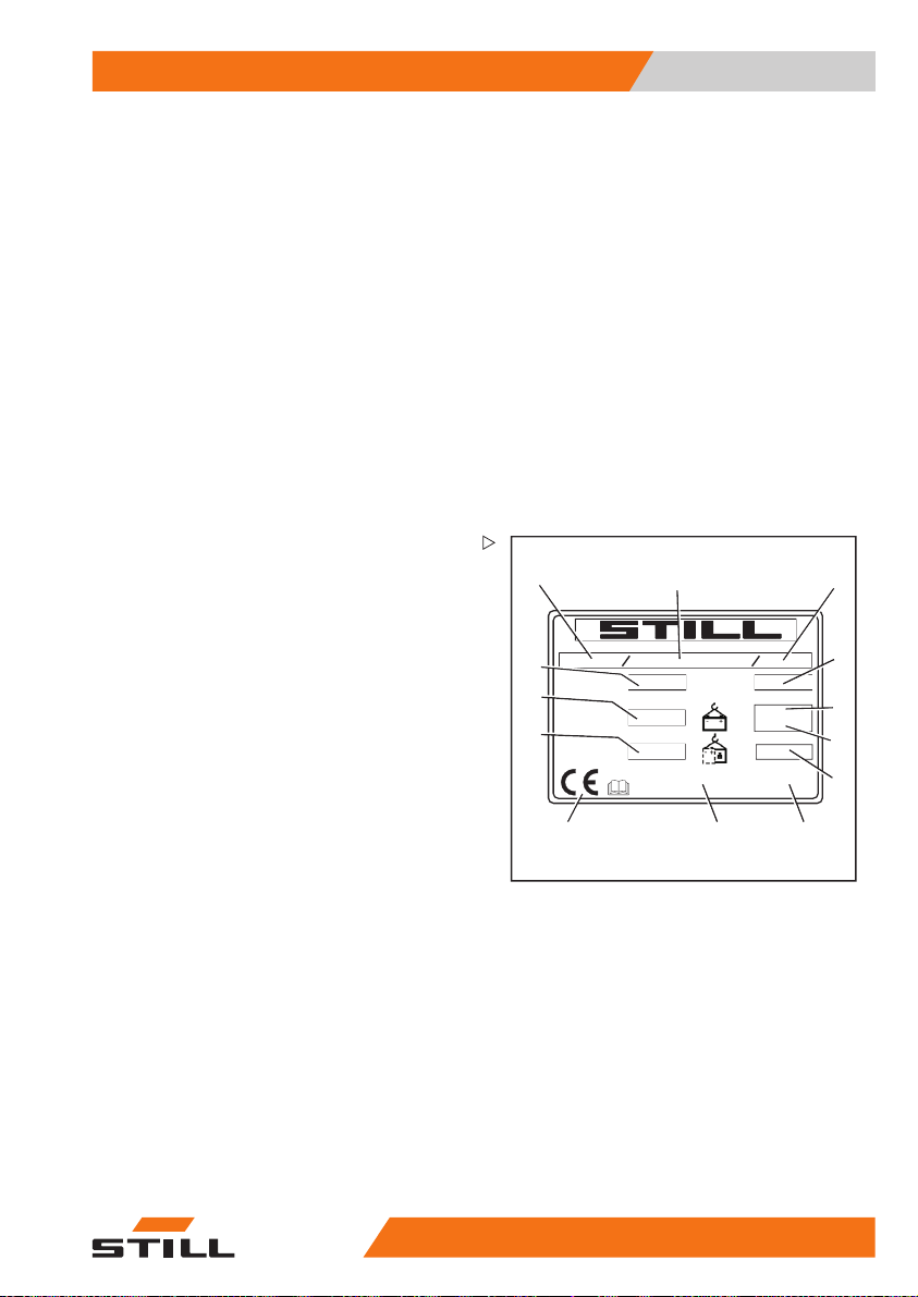
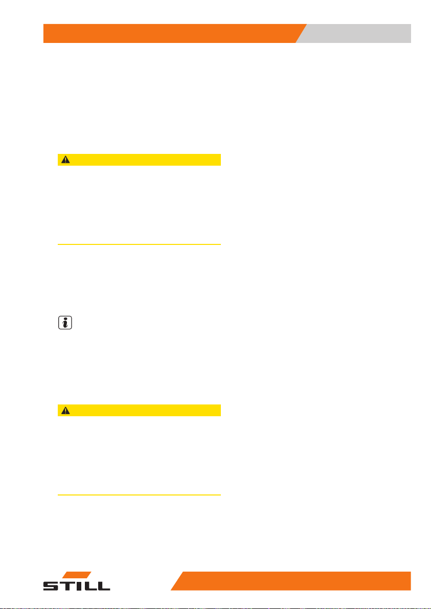
Nameplate
The truck can be identified from the information on the nameplate.
The information for the battery weights (5,
6) and the ballast weight (7) only applies to
electric forklift trucks.
12 Decal information: Hydraulic oil tank
13 Warning sign: Do not stand underneath the
fork/Do not stand on the fork
14 Decal information: Nameplate
15 Warning sign: Do not stand underneath the
fork/Do not stand on the fork/Danger due to
shearing/Danger due to high fluid pressure
16 Decal information: Caution/Read the op-
erating instructions/Fasten seat belt/Apply
parking brake when leaving the truck/Pas-
sengers are not allowed/Do not jump off if
the truck is tipping over/Lean in the opposite
direction to which the truck is tipping
17 Manufacturer's label text
18 Decal information: Caution/read operating
instructions/drive slowly with raised load
1
Type-Modèle-Typ / Serial no.-No. de série-Serien-Nr. / year-année-Baujahr
13
Rated capacity
Capacité nominale
Nenn-Tragfähigkeit
12
Battery voltage
Tension batterie
Batteriespannung
11
Rated drive power
Puissance motr.nom.
Nenn-Antriebsleist.
2
Unladen mass
kg
Masse à vide
Leergewicht
V
kW
* see Operating instructions
voir Mode d'emploi
siehe Betriebsanleitung
max
min.*
*
D-22113 Hamburg
Berzeliusstr. 10
kg
kg
kg
kg
3
4
5
6
7
10
9
6210_921-003_V3
1 Type
2 Production number
3 Year of manufacture
4 Tare weight in kg
5 Max. permissible battery weight in kg
6 Min. permissible battery weight in kg
7 Ballast weight in kg
8 Address of manufacturer
9 Refer to the technical data listed in these
operating instructions for more detailed
information
10 CE labelling
11 Nominal drive power in kW
12 Battery voltage in V
13 Rated capacity in kg
48011501 EN - 02/2018 9
550
8
Page 22
1 Foreword
Use of truck
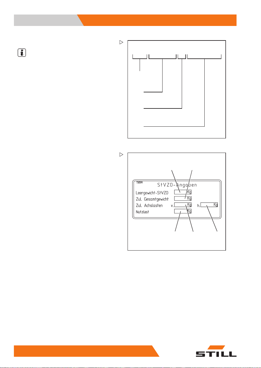
Production number
NOTE
The production number is used to identify the
truck. It can be found on the nameplate and
must be referred to in all technical questions.
The production number contains the following
coded information:
(1) Production location
(2) Model
(3) Year of manufacture
(4) Sequential number
StVZO (Road Traffic Licensing
Regulations) information
This label includes information on the weight
and load distribution of the truck.
xx xxxx x xxxxx
1
2
3
4
7090_921-004
12
Use of truck
Commissioning
Commissioning is the initial intended use of
the truck.
10 5
5048011501 EN - 02/2018
1Tareweig
2 Permitte
3 Permi
4Per
5 Payload (in kg)
ht (in kg)
d total weight (in kg)
tted front axle weight (in kg)
mitted rear axle weight (in kg)
5
34
7094_003-098
Page 23

Foreword 1
Use of truck
The necessary steps for the commissioning
vary depending on the model and equipment
of the truck. These steps require preparatory
work and adjustment work that cannot be performed by the operating company. See also
the chapter entitled "Definition of responsible
persons".
– To commission the truck, contact the
authorised service centre.
Proper usage
The truck described in these operating instructions is suitable for lifting, transporting
and stacking loads.
The truck may only be used
purpose as set out and des
operating instructions
If the truck is to be used for purposes other
than those specified in the operating instructions, the approval of the manufacturer and, if
applicable, the relevant regulatory authorities
must be obtained beforehand to prevent hazards.
The maximum load to be lifted is specified on
the capacity rating plate (load diagram) and
must not be exceeded; see also the chapter
entitled "Before picking up a load".
for its proper
cribed in these
.
Proper use during towing
This truck is suitable for the occasional towing
of trailers and is equipped with a towing device
for this purpose. This occasional towing may
not exceed 2% of the daily operating time. If
thetruckistobeusedfortowingonamore
regular basis, the manufacturer should be
consulted.
The regulations regardi
must be observed; see chapt
operation".
ng trailer operation
er "Trailer
48011501 EN - 02/2018 11
550
Page 24
1 Foreword
Use of truck
Impermissible use
The operating company or driver, and not the
manufacturer, is liable for any hazards caused
by improper use.
NOTE
Please observe the definition of the following
responsible persons: "operating company"
and "driver".
Use for purposes other than those described
in these operating instructions is prohibited.
DANGER
There is a risk of fatal injury from falling
off the truck while it is moving!
– It is prohibited to carry passengers
on the truck.
The truck may not be operated in areas where
there is a risk of fire, explosion or corrosion, or
in areas that are particularly dusty.
Stacking or unstacking is not permissible on
inclined surfaces or ramps.
Place of use
The truck can be used both outside and in
buildings. Operation on public roads is only
permitted if the "StVZO" (German Road Traffic
Licensing Regulations) equipment variant is
installed.
If the truck is to
the truck must conf
tions for the count
The ground must have an adequate load
capacity (concrete, asphalt) and a rough
surface. Roadways, working areas and aisle
widths must conform to the specifications in
these operating instructions; see the chapter
entitled "Roadways".
Driving on upward and downward gradients
is permitted provided the specified data and
specifications are observed, see the "Routes
"chapter.
12 5
be operated on public roads,
orm to the national regula-
ry in which it is being used.
5048011501 EN - 02/2018
Page 25
Foreword 1
Use of truck
The truck is suitable for indoor and outdoor
use in countries ranging from the Tropics to
Nordic regions (temperature range: -20°C to
+40°C).
If the truck is to be used in a cold store, it must
be configured accordingly and, if necessary,
approved for such an environment; see the
chapter entitled "Cold store application".
CAUTION
Batteries can freeze!
If the truck is parked in an ambient temperature of
below -10°C for an extended period, the batteries
will cool down. The electrolyte may freeze and
damage the batteries. The truck is then not ready
for operation.
– At ambient temperatures of below -10°C, only
park the truck for short periods of time.
The operating company must ensure suitable
fire protection for the relevant application in
the truck's surroundings. Depending on the
application, additional fire protection must be
provided on the truck. If in doubt, contact the
relevant authorities.
NOTE
Please observe the definition of the following
responsible person: "operating company".
Parking in temperatures below -10°C
CAUTION
Batteries ca
If the truck
below -10°C
will cool d
damage t
for opera
– When the a
n freeze!
is parked in an ambient temperature
for an extended period, the batteries
own. The electrolyte may freeze and
he batteries. The truck is then not ready
tion.
mbient temperature is below -10°C,
k the truck for short periods of time.
only par
48011501 EN - 02/2018 13
550
Page 26

1 Foreword
Use of truck
Using working platforms
WARNING
The use of working platforms is regulated by national law. The use of working platforms is only
permitted by virtue of the jurisdiction in the country
of use.
– Observe national legislation.
– Before using working platforms, consult the
national regulatory authorities.
14 5
5048011501 EN - 02/2018
Page 27

Foreword 1
Information about documentation
Information about documentation
Documentation scope
• Original operating instructions
• Original operating instructions for attachments (variant)
• Spare parts list
• Depending on the truck equipment, "UPA"
operating instructions may also be provided
NOTE
Refer to the additional information in the
section entitled "Rules for the operating
company of industrial trucks".
These operating instructions describe all
measures necessary for the safe operation
and proper maintenance of the truck in all
possible variants available at the time of
printing. Special versions to meet customer
requirements (UPA) are documented in
separate operating instructions. If you have
any questions, please contact your authorised
service centre.
Enter the production number and year of
manufacture from the nameplate in the space
provided:
Production numbe
Year of manufacture:
r:
Please quote the production number in all
technical enquiries.
Each truck comes with a set of operating
instructions. These instructions must be
stored carefully and must be available to the
driver and operating company at all times.
The storage location is specified in the chapter
entitled "Overviews".
If the operating instructions are lost, the operating company must obtain a replacement
from the manufacturer immediately.
The operating instructions are included in the
spare parts list and can be reordered as a
spare part.
48011501 EN - 02/2018 15
550
Page 28

1 Foreword
Information about documentation
The personnel responsible for operating and
maintaining the equipment must be familiar
with these operating instructions.
The operating company must ensure that all
users have received, read and understood
these operating instructions.
Safely store the complete do
pass on to the subsequent ope
when transferring or sellin
NOTE
Please observe the definition of the following
responsible persons: "operating company"
and "driver".
Thank you for reading and complying with
these operating instructions. If you have any
questions or suggestions for improvements,
or if you have found any errors, please contact
the authorised service centre.
Supplementary documentation
This industrial truck can be fitted with unplanned equipment () that deviates from the
standard equipment and/or the variants.UPA
The UPA may be, for example:
• Special sensors
• Special attachments
• Towing devices
• Customised attachments
In this case, the industrial truck has additional
documentation. This may be in the form of an
insert or separate operating instructions.
The original operating instructions for this
industrial truck are valid for the operation
of standard equipment and variants without
restriction. The operational and safety information in the original operating instructions
continues to be valid in its entirety unless it is
countermanded in this additional documentation.
The requirements for the qualification of
personnel as well as the time for maintenance
cumentation and
rating company
g the truck.
16 5
5048011501 EN - 02/2018
Page 29

Foreword 1
Information about documentation
may vary. This is defined in the additional
documentation.
– If you have any questions, please contact
your authorised service centre.
Issue date and topicality of the operating instructions
The issue date of these operating instructions
can be found on the title page.
STILL is constantly engag
development of trucks. Th
instructions are subject
claims based on the infor
illustrations containe
asserted.
Please contact your authorised service centre
for technical support relating to your truck.
ed in the further
ese operating
to change, and any
mation and/or
d in them cannot be
Copyright and trademark rights
These instructions must not be reproduced,
translated or made accessible to third parties—including as excerpts—except with the
express written approval of the manufacturer.
Explanation of information symbols used
DANGER
Indicates procedures that must be strictly adhered
to in order to prevent the risk of fatalities.
WARNING
Indicates proc
to in order to pr
Indicates procedures that must be strictly adhered
to in order to prevent material damage and/or
destruction.
edures that must be strictly adhered
event the risk of injuries.
CAUTION
48011501 EN - 02/2018 17
550
Page 30

1 Foreword
Information about documentation
NOTE
For technical requirements that require
special attention.
ENVIRONMENT NOTE
To prevent environmental damage.
List of abbreviations
NOTE
This list of abbreviations applies to all types
of operating instructions. Not all of the abbreviations that are listed here will necessarily
appear in these operating instructions.
Abbreviation
ABE
ArbSchG
BetrSichV
BG
BGG
BGR
DGUV
CE
CEE
DC Direct Current Direct current
DFÜ
DIN
EG
EN
FEM
F
max
Meaning
Display operating unit
Arbeitsschutzgesetz
Betriebssicherheitsverordnung
Berufsgenossenschaft
enossenschaftlicher Grundsatz
Berufsg
Berufsgenossenschaftliche Regel
Berufsgenossenschaftliche Vorschrift German accident prevention regulations
Communauté Européenne
Commission on the Rules for the Approval
the Electrical Equipment
of
Datenfernübertragung
Deutsches Institut für Normung German standardisation organisation
European Community
European standard
Fédération Européene de la Manutention
maximum Force
Explanation
German implementation of EU occupational health and safety directives
German implementation of the EU working
equipment directive
German insurance company for the company and employees
German pr
for occupat
German rules and recommendations for
occupational health and safety
Confirms conformity with product-specific
European directives (CE mark)
International commission on the rules for
the approval of electrical equipment
Remote data transmission
European Federation of Materials Handling and Storage Equipment
Maximum power
inciples and test specifications
ional health and safety
18 5
5048011501 EN - 02/2018
Page 31

Foreword 1
Information about documentation
Abbreviation
Meaning
Explanation
German authority for monitoring/issuing
GAA Gewerbeaufsichtsamt
regulations for worker protection, environmental protection, and consumer protection
GPRS General Packet Radio Service
Transfer of data packets in wireless
networks
ID no. ID number
ISO
International Organization for Standardization
International standardisation organisation
LAN Local Area Network Local area network
K
pA
LED
L
p
L
pAZ
LSP
MAK
Max. Maximum
Min. Minimum
PIN
PPE
SE
SIT
StVZO
TRGS
VD
VDI
VDMA
Uncertainty of measurement of sound
pressure levels
Light Emitting Diode Light emitting diode
Sound pressure level at the workplace
Average continuous sound pressure level
in the driver's compartment
Load centre of gravity
Maximum workplace concentration
Distance of the centre of gravity of the load
from the front face of the fork backs
Maximum permissible air concentrations
of a substance at the workplace
Highest value of an amount
Lowest value of an amount
al Identification Number
Person
Person
Personal protective equipment
Super-Elastic
Snap-In Tyre
Straßenverkehrs-Zulassungs-Ordnung
echnische Regel für Gefahrstoffe
T
Verband der Elektrotechnik Elektronik
E
Informationstechnik
Verein Deutscher Ingenieure
Verband Deutscher Maschinen- und
Anlagenbau e.V.
Superelastic tyres (solid rubber tyres)
Tyre
loos
Ger
s on public roads
cle
dinance on hazardous materials appli-
Or
cabl
German technical/scientific association
German technical/scientific association
German Mechanical Engineering Industry
Association
al identification number
s for simplified assembly, without
erimparts
man regulations for approval of vehi-
e in the Federal Republic of Germany
WLAN Wireless LAN Wireless local area network
.
48011501 EN - 02/2018 19
550
Page 32

1 Foreword
Information about documentation
Definition of directions
The directions "forwards" (1
"right" (2) and "left" (4) ref
position of the parts as seen f
compartment; the load is to th
), "backwards" (3),
er to the installation
rom the driver's
e front.
Schematic views
View of functions and operations
This documentation explains the (usually
sequential) chain of certain functions or operations. Schematic diagrams of a counterbalance truck are used to illustrate these procedures.
NOTE
These schematic diagrams are not representative of the structural state of the documented
truck. The diagrams are used solely for the
purpose of clarifying procedures.
1
4
2
3
6210_001-031
20 5
6210_003-062
5048011501 EN - 02/2018
Page 33

Foreword 1
Information about documentation
View of the display operating unit
NOTE
Views of operating statuses and values in
the display of the display operating unit are
examples and partly dependent on the truck
equipment. As a result, the displays shown
of the actual operating statuses and values
can vary. Information that is not relevant for
descriptions is not shown.
48011501 EN - 02/2018 21
550
Page 34

1 Foreword
Environmental considerations
Environmental considerations
Packaging
During delivery of the truck, certain parts
are packaged to provide protection during
transport. This packaging must be removed
completelyprior to initial start-up.
ENVIRONMENT NOTE
The packaging material must be disposed of
properly after delivery of the truck.
Disposal of components and batteries
The truck is composed of different materials. If
components or batteries need to be replaced
and disposed of, they must be:
•disposedof,
• treated or
• recycled in accordance with regional and
national regulations.
NOTE
The documentation provided by the battery
manufacturer must be observed when disposing of batteries.
ENVIRONMENT NOTE
We recommend working with a waste management company for disposal purposes.
22 5
5048011501 EN - 02/2018
Page 35

2
Safety
Page 36

2 Safety
Definition of responsible persons
Definition of responsible persons
Operating company
The operating company is the natural or legal
person or group who operates the truck or on
whose authority the truck is used.
The operating company must ensure that the
truck is only used for its proper purpose and in
compliance with the safety regulations set out
in these operating instructions.
The operating company must
all users read and understa
information.
The operating company is responsible for the
scheduling and correct performance of regular
safety checks.
We recommend that the national performance
specifications are adhered to.
Specialist
A qualified person is defined as a service
engineer or a person who fulfils the following
requirements:
• A completed vocation
demonstrably proves
expertise. This proo
a vocational qualifi
document.
• Professional experience indicating that
the qualified person has gained practical
experience of industrial trucks over a
proven period during their career During
this time, this person has become familiar
with a wide range of symptoms that require
checks to be carried out, such as based
on the results of a hazard assessment or a
daily inspection
• Recent professional involvement in the
field of the industrial truck test in question
and an appropriate further qualification
are essential. The qualified person must
have experience of carrying out the test
in question or of carrying out similar tests.
Moreover, this person must be aware of
the latest technological developments
cation or a similar
ensure that
nd the safety
al qualification that
their professional
f should consist of
24 5
5048011501 EN - 02/2018
Page 37

Safety 2
Definition of responsible persons
regarding the industrial truck to be tested
and the risk being assessed
Drivers
This truck may only be driven by suitable persons who are at least 18 years of age, have
been trained in driving, have demonstrated
their skills in driving and handling loads to
the operating company or an authorised representative, and have been specifically instructed to drive the truck. Specific knowledge
of the truck to be operated is also required.
The training requirements under §3 of the
Health and Safety at Work Act and §9 of the
plant safety regulations are deemed to have
been satisfied if the driver has been trained in
accordance with BGG (General Employers'
Liability Insurance Association Act) 925.
Observe the national regulations for your
country.
Driver rights, duties and rules of behaviour
The driver must be trai
duties.
The driver must be granted the required rights.
The driver must wear protective equipment
(protection suit, safety footwear, safety
helmet, industrial goggles and gloves) that
is appropriate for the conditions, the job and
the load to be lifted. Solid footwear should be
worn to ensure safe driving and braking.
Thedrivermustbefami
instructions and have ac
times.
The driver must:
• have read and understood the operating
manual
• have familiarised himself with safe operation of the truck
• be physically and mentally able t
truck safely
ned in his rights and
liar with the operating
cess to them at all
odrivethe
48011501 EN - 02/2018 25
550
Page 38

2 Safety
Definition of responsible persons
DANGER
The use of drugs, alcohol or medications that affect
reactions impair the ability to drive the truck!
Individuals under the influence of the aforementioned substances are not permitted to perform work
of any kind on or with the truck.
Prohibition of use by unauthorised
persons
The driver is responsib
working hours. He must n
rised persons to operat
When leaving the truck, the drivermust secure
it against unauthorised use, e.g. by pulling out
the key.
le for the truck during
ot allow unautho-
ethetruck.
26 5
5048011501 EN - 02/2018
Page 39

Safety 2
Essentials for safe operation
Essentials for safe operation
Insurance cover on company premises
In many cases, company premises are
restricted public traffic areas.
NOTE
The business liability insurance should be
reviewed to ensure that, in the event of any
damage caused in restricted public traffic
areas, there is insurance cover for the truck in
respect of third parties.
Changes and retrofitting
If the truck is used for work that is not listed
in the guidelines or in these instructions and
has to be converted or retrofitted accordingly,
you must note that any change to its structural
state can affect the handling and stability of
the truck, which in turn can lead to accidents.
You should therefore contact your service
centre beforehand.
Changes that will adversely affect stability,
load capacity and safety systems, among
other things, must not be made without the
manufacturer's approval.
The truck can only be converted with written
approval from the manufacturer. Approval
from the responsible authority must be obtained if necessary.
Changes to the brakes, steering, control
elements, circumferential view, equipment
variants (e.g. attachments) must also not be
made without the prior written approval of the
manufacturer.
We warn against the installation and use
of restraint systems not approved by the
manufacturer.
48011501 EN - 02/2018 27
550
Page 40

2 Safety
Essentials for safe operation
DANGER
Risk of injury if truck tips over!
Even when using an approved
restraint system, there is some
residual risk that the driver might
be injured if the truck tips over. This
risk of injury can be reduced through
the combined use of a restraint
system and the seat belt. In addition,
the seat belt protects against the
consequences of rear-end collisions
and falling off a ramp.
– Use the seat belt too.
When carrying out welding work on the
truck, it is essential that the battery and all
connections to the electronic control cards are
disconnected. Contact the authorised service
centre on this matter.
DANGER
Risk of explosion from additional holes
in the battery hood!
Explosive gases can escape and
lead to potentially fatal injuries if they
explode. Sealing holes with plugs
is not sufficient to prevent gas from
escaping.
– Do not drill any holes in the battery
hood.
DANGER
Risk of accident from additional holes in the battery
hood!
The rigidity of the battery hood is impaired and
the battery hood may fracture. The driver's seat
may collapse, leading to a risk of accident due to
uncontrolled steering movements whilst driving.
– Do not drill any holes in the battery hood.
28 5
5048011501 EN - 02/2018
Page 41

Safety 2
Essentials for safe operation
DANGER
Risk to life from falling load!
If the truck is not equipped with an overhead guard,
there is a risk to the driver's life, as he may be struck
by a load falling from a lift height of 1800 mm or
greater.
Operation of the truck without an overhead guard at
a lift height of over 1800 mm is prohibited.
– For lift heights of 1800 mm and above, only use
trucks with an overhead guard.
In the event of the manufacturer going into
liquidation and the company not being taken
over by another legal person, the operating
company can make changes to the truck.
To do so, the operati
the following prere
Construction documents, test documents
and assembly instructions associated with
the change must be archived and remain
accessible at all times.
Check that the capacity rating plate, decal information, hazard warnings and the operating
instructions are consistent with regard to the
changes and modify if necessary.
The change must be d
and implemented by
specialises in ind
with the standar
time the changes a
Decal information with the following data must
be permanently affixed to the truck so it is
clearly visible:
– Type of change
– Date of change
– Name and address of the company imple-
menting the change.
ng company must fulfil
quisites:
esigned, checked
a design office that
ustrial trucks in accordance
ds and directives valid at the
re made.
48011501 EN - 02/2018 29
550
Page 42

2 Safety
Essentials for safe operation
Changes to the overhead guard and roof loads
DANGER
In the event of the overhead guard failing due to
a falling load or the truck tipping over, there are
potentially fatal consequences for the driver. There
is a risk to life!
Welding and drilling on the overhead guard changes the material characteristics and the structural
design of the overhead guard. Excessive forces
caused by falling loads or the truck tipping over may
result in buckling of the modified overhead guard
andnoprotectionforthedriver.
– Do not perform welding on the overhead guard.
– Do not perform drilling on the overhead guard.
CAUTION
Heavy roof loads damage the overhead guard!
To ensure the stability of the overhead guard at
all times, a roof load may only be mounted on the
overhead guard if the structural design has been
tested and the manufacturer has given approval.
– Seek advice from the authorised service centre
for the mounting of roof loads.
Warning regarding non-original parts
Original parts, attachments and accessories
are specially designed for this truck. We
specifically draw your attention to the fact that
parts, attachments and accessories supplied
by other companies have not been tested and
approved by STILL.
CAUTION
Installation and/or use of such products may therefore have a negative impact on the design features
of the truck and thus impair active and/or passive
driving safety.
We recommend that you obtain approval from the
manufacturer and, if necessary, from the relevant
regulatory authorities before installing such parts.
The manufacturer accepts no liability for any damage caused by the use of non-original parts and
accessories without approval.
30 5
5048011501 EN - 02/2018
Page 43

Safety 2
Essentials for safe operation
Damage, defects and misuse of safety systems
Damage or other defects on the truck or
attachment must be reported to the supervisor
or responsible fleet manager immediately so
that they can have the defect rectified.
Trucks and attachments that are not functional
or safe to drive may not be used until they have
been properly repaired.
Do not remove or deactivate
and switches.
Fixed set values may only be changed with the
approval of the manufacturer.
Work on the electrical system(e.g. connecting
a radio, additional headlights etc.) is only
permitted with the manufacturer's written
approval. All electrical system interventions
must be documented.
Even if they are removabl
not be removed, as they a
protect against small f
safety systems
e, roof panels may
re designed to
alling objects.
Tyres
DANGER
Risk to stability!
Failure to observe the following information and
instructions can lead to a loss of stability. The truck
may tip over, risk of accident!
Thefollowingfactorscanleadtoalossof
stability and are therefore prohibited:
• Different tyres on the same axle, e.g.
pneumatic tyres and superelastic tyres
• Tyres not approved by the manufacturer
• Excessive tyre wear
• Tyres of inferior quality
• Changing rim wheel parts
• Combining rim wheel parts from different
manufacturers
48011501 EN - 02/2018 31
550
Page 44

2 Safety
Essentials for safe operation
The following rules must be observed to
ensure stability:
• Only use tyres with equal and permitted
levels of wear on the same axle
• Only use wheels and tyres of the
on the same axle, e.g. only supe
tyres
• Only use wheels and tyres approved by the
manufacturer
• Only use high-quality products
Wheels and tyres approved by
facturer can be found on the s
If other wheels or tyres are t
thorisation from the manu
obtained beforehand.
– Contact the authorised service centre on
this matter.
When changing wheels or tyres, always
ensure that this does not cause the truck to
tilt to one side (e.g. always replace righthand and left-hand wheels at the same
time). Changes must only be made following
consultation with the manufacturer.
Ifthetypeoftyreusedon
for example from superel
matic tyres, the load dia
accordingly.
– Contact the authorised service centre on
this matter.
facturer must be
an axle is changed,
astic tyres to pneu-
gram must be changed
same type
relastic
the manu-
pare parts list.
o be used, au-
Medical equipment
WARNING
Electromagneticinterferencemayoccuron medical
devices!
Only use equipment that is sufficiently protected
against electromagnetic interference.
Medical equipment, such as pacemakers or
hearing aids, may not work properly when the
truck is in operation.
– Ask your doctor or the manufacturer of
the medical equipment to confirm that the
medical equipment is sufficiently protected
against electromagnetic interference.
32 5
5048011501 EN - 02/2018
Page 45

Safety 2
Essentials for safe operation
Exercise caution when handling gas springs and accumulators
WARNING
Gas springs are under high pressure. Improper
removal results in an elevated risk of injury.
For ease of operation, various functions on the
truck can be supported by gas springs. Gas springs
are complex components that are subject to high
internal pressures (up to 300 bar). They may under
no circumstances be opened unless instructed to
do so, and may be installed only when not under
pressure. If required, the authorised service centre
will depressurise the gas spring in accordance with
the regulations before removal. Gas springs must
be depressurised before recycling.
– Avoid damage, lateral forces, buckling, tempe-
ratures over 80°C and heavy contamination.
– Damaged or defective gas springs must be
changed immediately.
– Contact the authorised service centre.
WARNING
Accumulato
installati
risk of inj
Before sta
depressu
– Contact th
rs are under high pressure. Improper
on of an accumulator results in an elevated
ury.
rting work on the accumulator it must be
rised.
e authorised service centre.
Length o
ftheforkarms
DANGER
Risk of accident due to the incorrect selection of
fork arms!
– The fork arms must match the depth of the load.
If the fork arms are too short, the load may
fall off the arms after it has been picked up.
In addition, be aware that the load centre of
gravity may shift as a result of dynamic forces,
such as braking. A load that is otherwise
resting safely on the fork arms may move
forwards and fall.
If the fork arms are too long, they can catch
on loading units behind the load that is to be
48011501 EN - 02/2018 33
550
Page 46

2 Safety
Essentials for safe operation
picked up. These other loading units then fall
over when the load is raised.
– For help with selecting the correct fork arms,
contact the authorised service centre.
34 5
5048011501 EN - 02/2018
Page 47

Safety 2
Residual risk
Residual risk
Residual dangers, residual risks
Despite careful working and compliance with
standards and regulations, the occurrence
of other risks when using the truck cannot be
entirely excluded.
The truck and all other system components
comply with current safety requirements.
Nevertheless, even when the truck is used
for its proper purpose and all instructions
are followed, some residual risk cannot be
excluded.
Even beyond the narrow dan
truck itself, a residual r
Persons in this area aroun
exercise a heightened deg
so that they can react imme
of any malfunction, incid
WARNING
All persons that are in the vicinity of the truck
must be instructed regarding these risks that arise
through use of the truck.
In addition, we draw attention to the safety regulations in these operating instructions.
ger areas of the
isk cannot be excluded.
d the truck must
ree of awareness,
diately in the event
ent or breakdown etc.
Risks can include:
• Escape of consumables due to leakages,
rupture of lines and containers etc.
• Risk of accident when driving over difficult
ground such as gradients, smooth or
irregular surfaces, or with poor visibility
etc.
• Falling, tripping etc. when moving on
the truck, especially in wet weather, with
leaking consumables or on icy surfaces
• Fire and explosion risks due to batteries and
electrical voltages
• Human error resulting from failure to
observe the safety regulations,
• Unrepaired damage or defective and worn
components,
• Insufficient maintenance and testing
• Use of incorrect consumables
• Exceeding test intervals
48011501 EN - 02/2018 35
550
Page 48

2 Safety
Residual risk
The manufacturer is not held responsible for
accidents involving the truck caused by the
failure of the operating company to comply
with these regulations either intentionally or
carelessly.
Stability
The stability of the truck has been tested to the
latest technological standards and is guaranteed provided that the truck is used properly
and according to its intended purpose. These
standards only take into account the dynamic
and static tipping forces that can arise during
specified use in accordance with the operating rules and intended purpose. However, the
danger of exceeding the moment of tilt due to
improper use or incorrect operation and losing
stability can never be excluded.
The loss of stability can b
imised by the following ac
– Always secure the load against slipping,
e.g. by lashing.
– Always transport unstable loads in suitable
containers.
– Always drive slowly when
– Drive with the load lowered.
– Even with sideshifts, align the load as
centrally as possible with the truck and
transport in this position.
– Avoid turning and diagon
slopes or gradients.
– Never have the load facing downhill when
travelling on slopes or gradients.
– Pick up only loads of the approved width.
– Always take great care wh
suspended loads.
– Do not drive over ramp edges or steps.
e avoided or min-
tions:
cornering.
ally driving across
en transporting
Special risks associated with using the truck and attachments
Approval from the manufacturer and attachment manufacturer must be obtained each
36 5
5048011501 EN - 02/2018
Page 49

Safety 2
Residual risk
time the truck is used in a manner that falls
outside the scope of normal use, and in cases
where the driver is not certain that he can use
the truck correctly and without the risk of accidents.
48011501 EN - 02/2018 37
550
Page 50

2 Safety
Residual risk
Overview of hazards and countermeasures
NOTE
This table is intended to help evaluate the
hazards in your facility and applies to all drive
types. It does not claim to be complete.
– Observe the national regulations for the
country in which the truck is being used.
Hazard Measure
Truck equipment does
not comply with local
regulations
Lackofskillsand
qualification of driver
Usage by unauthorised
persons
Truck not in a safe
condition
Risk of falli
using working
platforms
Impaired visibility due
to load
Contamination of
respiratory air
ng when
Test
Driver training (sit-on
and stand-on)
Access with key only
for authorised persons
Recurrent testing and
rectification of defects
Compliance wi
national regul
(different nat
Resource planning
Assessment of diesel
exhaust gases
Assessment of LPG
exhaust gases
th
ations
ional laws)
Check note
√ Complete
- Not applicable
O If in doubt, consult
O BGG 925
O
O German Ordinance on
O German Ordina
O German Ordi
O
O German threshold limit
Notes
competent factory
inspectorate or
employers' liability
insurance association
VDI 3313 driver permit
Industrial Safety and
Health (BetrSichV)
nce
on Industria
and Health (B
and employer's
insurance assoc
Industri
Health (B
Techn
for Ha
Sub
554
Ord
afety and Health
S
BetrSichV)
(
values list (MAK-Liste)
and the German
Ordinance on Industrial
Safety and Health
(BetrSichV)
l Safety
etrSichV)
liability
iations
nance on
al Safety and
etrSichV)
ical Regulations
zardous
stances (TRGS)
and the German
inance on Industrial
38 5
5048011501 EN - 02/2018
Page 51

Safety 2
Residual risk
Hazard Measure
Impermissible usage
(improper usage)
When fuelling
a) Diesel Note the German
b) LPG Note German Social
Issuing of operating
instructions
Written notice of
instruction to driver
Note the German
Ordinance on
Industrial Safety and
Health (BetrSichV),
the operating
instructions and the
German Engineering
Federation (VDMA)
rules
Ordinance on
Industrial Safety and
Health (BetrSichV),
the operating
instructions and the
German Engineering
Federation (VDMA)
rules
Accident Insurance
(DGUV) regulation
D34, the operating
instructions and the
German Engineering
Federation (VDMA)
rules
Check note
√ Complete
- Not applicable
O German Ordinance on
O German Ordinance on
O
O
O
Notes
Industrial Safety and
Health (BetrSichV) and
German Health and
labour protection law
(ArbSchG)
Industrial Safety and
Health (BetrSichV) and
German Health and
labour protection law
(ArbSchG)
48011501 EN - 02/2018 39
550
Page 52

2 Safety
Residual risk
Hazard Measure
When charging the
traction battery
Note the German
Ordinance on
Industrial Safety and
Health (BetrSichV),
the operating
instructions and the
German Engineering
Federation (VDMA)
rules
When using battery
chargers
Note the German
Ordinance on
Industrial Safety and
Health (BetrSichV),
employers' liability
insurance association
regulation 104 and the
operating instructions
When parking LPG
trucks
Note the German
Ordinance on
Industrial Safety and
Health (BetrSichV),
employers' liability
insurance association
regulation 104 and the
operating instructions
With driverless transport systems
Roadway quality
Clean/clear driveways O German Ordinance on
inadequate
Load carrier
Reattach load to pallet
incorrect/slipped
Drive behaviour
Employee training
unpredictable
Driveways blocked Mark driveways
Keep driveways clear
Driveways intersect
Announce right-of-way
rule
No person detection
Employee training
during depositing and
retrieval
.
Check note
√ Complete
- Not applicable
O Association for
O German Ordinance
O German Ordinance
O German Ordinance on
O German Ordinance on
O German Ordinance on
O German Ordinance on
O German Ordinance on
Notes
Electrical, Electronic
and Information
Technologies (VDE)
regulation 0510: In
particular
- Ensure adequate
ventilation
- Insulation value within
the permissible range
on Industrial Safety
and Health (BetrSichV)
and employers' liability
insurance association
regulation 104
on Industrial Safety
and Health (BetrSichV)
and employers' liability
insurance association
regulation 104
Industrial Safety and
Health (BetrSichV)
Industrial Safety and
Health (BetrSichV)
Industrial Safety and
Health (BetrSichV)
Industrial Safety and
Health (BetrSichV)
Industrial Safety and
Health (BetrSichV)
Industrial Safety and
Health (BetrSichV)
40 5
5048011501 EN - 02/2018
Page 53

Safety 2
Residual risk
Danger to employees
According to the German Ordinance on Industrial Safety and Health (BetrSichV) and labour
protection law (ArbSchG), the operating company must determine and assess hazards
during operation, and establish the labour
protection measures required for employees (BetrSichVO). The operating company
must therefore draw up appropriate operating
instructions (§ 6 ArbSchG) and make them
available to the driver. A responsible person
must be appointed.
NOTE
Please observe the definition of the following
responsible persons: "operating company"
and "driver".
The construction and equipment of the
truck correspond to the Machinery Directive
2006/42/EC and are therefore marked with
CE labelling. These elements are therefore
not included in the hazard assessment. Attachments possess their own CE labelling and
likewise are not included for that reason. The
operating company must, however, select the
type and equipment of the trucks so as to comply with the local provisions for deployment.
The result must be documented (§ 6 ArbSchG). In the case of truck applications involving similar hazard situations, the results may
be summarised. This overview (see chapter
"Overview of hazards and countermeasures")
provides help on complying with this regulation. The overview specifies the main hazards
that are the most frequent cause of accidents
in the event of non-compliance. If other major
operational hazards are involved, they must
also be taken into consideration.
The conditions of use for trucks are broadly
similar in many plants, so the hazards can
be summarised in one overview. Observe
the information provided by the relevant
employers' liability insurance association on
this subject.
48011501 EN - 02/2018 41
550
Page 54

2 Safety
Safety tests
Safety tests
Regular safety inspection of the truck
Safetyinspectionbasedontimeand
extraordinary incidents
The operating company must ensure that the
truck is checked by a specialist at least once a
year or after particular incidents.
As part of this inspection
of the technical conditio
performed with regard to a
In addition, the truck mus
checked for damage that co
have been caused by impro
log must be created. The r
inspection must be retai
inspections have been ca
The inspection date is indicated by an adhesive label on the truck.
– Arrange for the service centre to perform
periodic safety inspections on the truck.
– Observe guidelines fo
on the truck in accorda
The operator is responsible for ensuring any
defects are remedied without delay.
– Contact your service centre.
, a complete check
n of the truck must be
ccident safety.
t be thoroughly
uld potentially
per use. A test
esults from the
ned until a further two
rried out.
r checks carried out
nce with FEM 4.004.
NOTE
Observe the national regulations for your
country!
Insulation testing
The insulation of the truck must have sufficient
insulation resistance. For this reason, insulation testing in accordance with DIN EN 1175
and DIN 43539, VDE 0117 and VDE 0510
must be conducted at least once yearly as part
of the FEM testing.
The insulation testing results must be at least
the test values given in the following two
tables.
– For insulation testing, contact the autho-
rised service centre.
42 5
5048011501 EN - 02/2018
Page 55

Safety 2
Safety tests
The exact procedure for this insulation testing
is described in the workshop manual for this
truck.
NOTE
The truck's electrical system and drive batteries must be checked separately.
Test values for the drive battery
Component
Battery
.
Recommended
test voltage
Measurements
50 VDC 24 volts > 1200 Ω
100 VDC 48 volts > 2400 Ω
Batt+
Batt-
Battery tray
100 VDC
Nominal voltage
U
Batt
80 volts > 4000 Ω
Test values
Test values for the entire truck
Nominal voltage Test voltage
Test values for new trucks
24 volts 50 VDC Min. 50 kΩ > 24 kΩ
48 volts 100 VDC Min. 100 kΩ > 48 kΩ
80 volts 100 VDC Min. 200 kΩ > 80 kΩ
.
Minimum values over the
duration of the service life
48011501 EN - 02/2018 43
550
Page 56

2 Safety
Safety regulations for handling co
nsumables
Safety regulations for handling consumables
Permissible consumables
DANGER
Failure to observe the safety regulations relating to
consumables may result in a risk of injury, death or
damage to the environment.
– Observe the safety regulations when handling
such materials.
Refer to the maintenance data table for the
permissible substances that are necessary for
operation (see ⇒ Chapter "Maintenance data
table", P. 5-331).
Oils
DANGER
Oils are flammable!
– Follow the statutory regulations.
– Donotallowoilstocomeinto
contact with hot engine parts.
– No smoking, fires or naked flames!
DANGER
Oils are toxic!
– Avoid contact a
– If vapour or f
move to fres
– In the event
eyes, rins
10 minute
consult a
–Ifswallow
vomitin
attenti
44 5
nd consumption.
umes are inhaled,
h air immediately.
of contact with the
e thoroughly (for at least
s) with water and then
n eye specialist.
ed, do not induce
g. Seek immediate medical
on.
5048011501 EN - 02/2018
Page 57

Safety 2
nsumables
WARNING
Prolonged intensive contact with the
skin can result in dryness and irritate
the skin!
– Avoid contact and consumption.
– Wear protective gloves.
– After any contact, wash the skin
with soap and water, and then apply
askincareproduct.
– Immediately change soaked
clothing and shoes.
WARNING
There is a risk of slipping on spilled oil, particularly
when combined with water!
– Spilt oil should be removed immediately with
oil-binding agents and disposed of according to
the regulations.
ENVIRONMENT NOTE
Safety regulations for handling co
Oil is a water-polluting substance!
•
Always store oil in containers that comply
with the applicable regulations.
•
Avoid spilling oils.
•
Spilt oil should be removed immediately
with oil-binding agents and disposed of
according to the regulations.
•
Dispose of old oils according to the regulations.
Hydraulic fluid
These fluids are pressurised during
operation of the truck and are hazardous to your health.
– Do not spill the fluids.
– Follow the statutory regulations.
– Donotallowthefluidstocomeinto
contact with hot engine parts.
WARNING
48011501 EN - 02/2018 45
550
Page 58

2 Safety
Safety regulations for handling co
WARNING
These fluids are pressurised during
operation of the truck and are hazardous to your health.
– Do not allow the fluids to come into
contact with the skin.
– Avoid inhaling spray.
– Penetration of pressurised fluids
into the skin is particularly danger-
ous if these fluids escape at high
pressure due to leaks in thehydrau-
lic system. In case of such injury,
immediate medical assistance is
required.
– To avoid injury, use appropriate
personal protective equipment
(e.g. protective gloves, industrial
goggles, skin protection and skin
care products).
ENVIRONMENT NOTE
Hydraulic fluid is a water-polluting substance.
•
Always store hydraulic fluid in containers
that comply with regulations
•
Avoid spills
•
Spilt hydrauli
immediately wit
disposed of acco
•
Dispose of old hydraulic fluid according to
c fluid should be removed
h oil-binding agents and
rding to the regulations
the regulations
nsumables
Battery acid
WARNING
Battery acid contains dissolved
sulphuric acid. This is toxic.
– Avoid touching or swallowing the
battery acid at all costs.
– In case of injury, seek medical
advice immediately.
46 5
5048011501 EN - 02/2018
Page 59

Safety 2
nsumables
WARNING
Battery acid contains dissolved
sulphuric acid. This is corrosive.
– When working with battery acid,
use appropriate PSA (rubber
gloves, apron, protection goggles).
– When working with battery acid,
neverwearawatchorjewellery.
– Do not allow any acid to get
onto clothing or skin or into the
eyes. If this does happen, rinse
immediately with plenty of clean
water.
– In case of injury, seek medical
advice immediately.
– Immediately rinse away spilt
battery acid with plenty of water.
– Follow the statutory regulations.
ENVIRONMENT NOTE
– Dispose of used battery acid in line with the
applicable regulations.
Safety regulations for handling co
Brake fluid
WARNING
Brake fluid is poisonous!
– Avoid swallowing. In the event of
swallowing, do not induce vomiting.
Rinse out your mouth thoroughly
with water and ask a doctor for
advice.
– Avoid aerosolisation and inhala-
tion. In the event of inhalation, seek
fresh air. Ask a doctor for advice if
necessary.
48011501 EN - 02/2018 47
550
Page 60

2 Safety
Safety regulations for handling co
WARNING
Brake fluid is hazardous to your
health!
Brake fluid irritates the eyes and
can dry out the skin upon prolonged
contact.
– Coat your hands with a protective
skincreampriortostartingwork.
– Avoid prolonged or intensive
skin contact. In the event of skin
contact, clean the wetted skin with
water and soap, and subsequently
apply a skin care product.
– Prevent contact with the eyes. In
the event of contact with the eyes,
wash out the affected eye(s) with
clean water for ten minutes and
then ask a doctor for advice.
– Change clothing soiled with brake
fluid as soon as possible.
CAUTION
Brake fluid is flammable!
– Do not allow brake fluid to come into contact with
hot motor parts.
– Smoking, fires and naked flames are prohibited.
nsumables
CAUTION
Brake fluid has strong dissolving and colour-changing properties.
– Immediately rinse off any brake fluid that has
splashed on paint, clothing, and shoes with
plenty of water
ENVIRONMENT NOTE
Brake fluid is a water pollutant!
•
Always store brake fluid in containers
complying with the regulations..
•
Do not spill b
•
Spilt brake fluid must be removed immedia-
rake fluid.
tely using an oil binding agent and disposed
of in accordance with regulations
•
Dispose of old brake fluid according to the
regulations.
•
Observe the nati
country in which
48 5
onal regulations for the
the truck is being used.
5048011501 EN - 02/2018
Page 61

Safety 2
Safety regulations for handling co
nsumables
Disposal of consumables
ENVIRONMENT NOTE
Materials that accumulate during repair,
maintenance and cleaning must be collected
properly and disposed of in accordance with
the national regulations for the country in
which the truck is being used. Work must
only be carried out in areas designated for the
purpose. Care must be taken to minimise any
environmental pollution.
– Soak up any spilt fluids such as hydraulic
oil, brake fluid or gearbox oil using an
oil-binding agent.
– Neutralise any spilt battery acid immedi-
ately.
– Always observe national regulations con-
cerning the disposal of used oil.
48011501 EN - 02/2018 49
550
Page 62

2 Safety
Emissions
Emissions
The values specified apply to a standard truck
(compare the specifications in the "Technical
data" chapter). Different tyres, lift masts,
additional units etc. may produce different
values.
Noise emissions
The values were determined based on
measuring procedures from the standard
EN 12053 "Safety of industrial trucks. Test
methods for measuring noise emissions",
based on EN 12001 and EN ISO 3744 and the
requirements of EN ISO 4871.
L
pAZ
lowing sound
This machine emits the fol
pressure levels:
Continuous sound pressure level in the
driver's compartment
<70dB(A)
The values were determ
on an identical machin
values for operating s
Time proportions:
• Lifting 18%
• Idling 58%
• Driving 24%
However, the indicated noise levels at the
truck cannot be used to determine the noise
emissionsat workplaces according to the most
recent version of Directive 2003/10/EC (daily
personal noise pollution). If required, these
noise emissions must be determined directly
at the workplaces under the actual conditions
present (further sources of noise, particular
application conditions, sound reflections) by
the operating company.
NOTE
ined in the test cycle
e from the weighted
tatuses and idling.
Please observe the definition of the following
responsible person: "operating company".
50 5
5048011501 EN - 02/2018
Page 63

Safety 2
Emissions
Vibrations
The vibrations of the machine have been
determined on an identical machine in accordance with the standards DIN EN 13059
"Safety of industrial trucks - Test methods
for measuring vibration" and DIN EN 12096
"Mechanical vibration - Declaration and verification of vibration emission values".
Frequency-weighted effective value of acceleration on the seat
MSG 65 driver's seat
0.68 m/s
2
Tests have indicated that the amplitude of the
hand and arm vibrations on the steering wheel
or the operating devices in trucks is less than
2
2.5 m/s
. There are therefore no measure-
ment guidelines for these measurements.
The individual vibrati
over the course of a work
determined by the oper
accordance with Direc
the actual place of use
additional influences
intensity of use etc.
Measurement
uncertainty
0.204 m/s
2
on load on the driver
ing day must be
ating company in
tive 2002/44/EC at
in order to consider all
, such as driving route,
NOTE
Please observe the definition of the following
responsible person: "operating company".
48011501 EN - 02/2018 51
550
Page 64

2 Safety
Emissions
Battery
DANGER
Risk of explosion due to flammable
gases!
During charging, the lead-acid battery
releases a mixture of oxygen and
hydrogen (oxyhydrogen gas). This
gas mixture is explosive and must not
be ignited.
– Make sure that there is always
sufficient ventilation in working
areas that are entirely or partially
enclosed.
– Keep away from open flames and
flying sparks
– Do not smoke.
– Observe the instructions in the
chapter entitled Safety regulations
when handling the battery.
Radiation
According to the guidelines DIN EN 62471:2009-03
(VDE 0837-471:2009-03), the STILL SafetyLight (variant) is assigned to risk group 2 due
to its photobiological hazard potential.
52 5
5048011501 EN - 02/2018
Page 65

3
Overviews
Page 66

3 Overviews
Full view
Full view
1
2
12
3
11
10
9
1Liftmast
2 Overhead guard
3 Driver's compartment
4 Battery door
5 Battery hood
6 Connection for towing bracket / tow coupling
(optional)
8
7 Drive wheel
8 Right-hand bottom plate
9 Left-hand bottom plate
10 Running axle
11 Fork arms
12 Lift cylinder
4
5
5060_003-094_V2
6
7
54 5
5048011501 EN - 02/2018
Page 67

Overviews 3
Full view
48011501 EN - 02/2018 55
550
Page 68

3 Overviews
4
General view of driver's compartme
nt
General view of driver's compartment
15
14
13
1
34
2
5
6
7
8
9
5060_003-093_V2
12
1 Parking brake lever
2 Steering wheel
3Switchkey
4 Display operating unit
5 Document holder and storage location for
operating instructions
6 Operating devices for hydraulic and traction
functions
7 Emergency off switch (only in this position in
multi-lever operation)
56 5
11
5048011501 EN - 02/2018
10
8 Storage box
9 Cup holder for bottles max. 1 l
10 Battery hood handle
11 Battery hood release
12 Driver's seat
13 Accelerator pedal
14 Brake pedal
15 Signal horn foot switch
Page 69

Overviews 3
4
Shelf and cup holder
Shelf and cup holder
WARNING
Objects may fall into the footwell and obstruct the
pedals — there is risk of accident!
Objects to be stored must be of the correct size so
they do not fall from the shelves (1, 2) or out of the
cup holder (3). Objects that fall into the footwell
during travel as a result of steering or braking can
slip between the pedals (4) and stop them working
correctly. The truck may subsequently not be able
to be braked when necessary.
– Bottles of 1 l or smaller may be stored in the cup
holder.
– Make sure that stored objects cannot fall from
the shelves when the truck is started up, steered
and braked.
1
4
2
3
5060_003-165
48011501 EN - 02/2018 57
550
Page 70

3 Overviews
Operating devices and display elem
ents
Operating devices and display elements
Display operating unit
56
4
3
2
1
26
25
21
20
6210_003-082_V3
1 Hazard warning system button
2 Front windscreen wiper button
3 Working spotlight button
4 Drive programme selector button
5 Lighting button
6 Lighting symbol
7 Not assigned
8 Battery charge display
9 Drive programme display (numerical)
10 Left direction indicator light
11 Forward travel display
12 Right direction indicator light
13 Malfunction display
24
22
23
7
19
17
18
14 Reverse travel display
15 Power rating display
16 Time display (digital)
17 Not assigned
18 Rotating beacon display
19 Interior light display
20 Rear window heating display
21 Interior light/rotating beacon button
22 Rear window heating button
23 Menu change button
24 Lighting button
25 Blue-Q button
26 Rear window wiper button
8
9
10
11
12
13
14
15
16
NOTE
The buttons (5, 21, 22) and the corresponding
indicators (6, 7, 18, 19, 20) are assigned
according to the auxiliary equipment installed.
The assignment shown here is an example
and may differ from the assignment actually
programmed on the truck. Buttons may be
assigned multiple functions that are called
up according to the menu navigation. For
further information, see the section entitled
"Operating the display and operating unit".
– If you have any questions, please contact
your authorised service centre.
58 5
5048011501 EN - 02/2018
Page 71

Overviews 3
Operating devices and display elem
ents
Operating devices for hydraulic and traction functions
Different versions of the operating devices are
available for operating the truck's hydraulic
and traction functions.
The truck can be equipped with the following
operating devices:
• Multiple-lever
• Double mini-lever
• Triple mini-lever
• Quadruple mini-lever
• Joystick 4Plus
• Fingertip
• Mini-console
48011501 EN - 02/2018 59
550
Page 72

3 Overviews
Operating devices and display elem
Multi-lever
ents
123
6
1 "Lift/lower" operating lever
2 "Tilt" operating lever
3 Operating lever for attachment (variant)
4 Operating lever for attachments with 5th
function (variant)
5 "5th function" function switch (variant)
6 Drive direction switch
4
5
5060_003-168
NOTE
In the dual-pedal version (variant), the truck is
equipped with a signal horn button instead of
the drive direction switch.
60 5
5048011501 EN - 02/2018
Page 73

Overviews 3
Operating devices and display elem
ents
Double mini-lever
3
2
1
8
1 "Lift mast" 360° lever
2 Function key F1
3 Function key F2
4 "Drive direction / turn indicator" cross lever
4
F1
F2
7312_003-002
5 Function key "5th function"
6 "Attachments" cross lever
7 Emergency stop switch
8 Signal horn button
5
6
7
NOTE
Depending on the specification, various
electric attachment parts can be controlled
via function keys (2) and (3). Changes must
only be made by the authorised service centre.
48011501 EN - 02/2018 61
550
Page 74

3 Overviews
Operating devices and display elem
Three-way mini-lever
ents
3
2
1
9
1 "Lift mast" 360° lever
2 Function key F1
3 Function key F2
4 "Drive direction / turn indicator" cross lever
5 Function key "5th function"
NOTE
ding on the specification, various
Depen
c attachment parts can be controlled
electri
tion keys (2) and (3). Changes must
via func
only be m
ade by the authorised service centre.
4
5
6
7
5060_003-089
6 "Auxiliary hydraulics 1" operating lever
7 "Auxiliary hydraulics 2" operating lever
8 Emergency stop switch
9 Signal horn button
8
62 5
5048011501 EN - 02/2018
Page 75

Overviews 3
Operating devices and display elem
ents
Four-way mini-lever
4
3
2
1
10
1 "Lift/lower"
2 "Tilt" opera
3 Function ke
4 Function k
5 "Drive di
NOTE
Depending on the specification, various
electric attachment parts can be controlled
via function keys (3) and (4). Changes must
only be made by the authorised service centre.
operating lever
ting lever
yF1
ey F2
rection / turn indicator" cross lever
5
6
5060_003-088
6 Function key "
7 "Auxiliary h
8 "Auxiliary
9 Emergency
10 Signal ho
ydraulics 1" operating lever
hydraulics 2" operating lever
rn button
7
8
9
5th function"
stop switch
48011501 EN - 02/2018 63
550
Page 76

3 Overviews
Operating devices and display elem
Joystick 4Plus
ents
9
1
8
7
6
5
1 Horizontal rocker button for "3rd hydraulic
function", tilt the lift mast
2 Pictograms for the basic hydraulic functions
3 Pictograms for the 5th hydraulic function and
the clamp locking mechanism (variant)
4 Pictograms for the 3rd & 4th hydraulic
functions
2
3
6210_003-087
4
5 LED for clamp locking mechanism (variant)
6 Slider for the "4th hydraulic function", e.g.
reach frame forwards/backwards
7 Vertical rocker button for the "drive direction"
8Shiftkey"F"
9 Signal horn button
64 5
5048011501 EN - 02/2018
Page 77

Overviews 3
F1
F2
Operating devices and display elem
ents
Fingertip
1
12
23456
F2
F1
11
10
7
89
1 Function key F1
2 Function key F2
3 Left-hand turn indicator button
4 Signal horn button
5 Right-hand turn indicator button
6 Button for 5th function
NOTE
Depending on the specification, various
electric attachment parts can be controlled
via function keys (1) and (2). Changes must
only be made by the authorised service centre.
48011501 EN - 02/2018 65
550
6321_003-004
7 Emergency stop switch
8 "Attachments" operating lever
9 "Attachments" operating lever
10 "Tilt" operating lever
11 "Lift/lower" operating lever
12 Travel direction switch
Page 78

3 Overviews
Operating devices and display elem
Mini console
The mini console is located on the steering
column below the steering wheel.
ents
2
1
1 Travel direction switch
2 Direction indicator switch
7311_003-056
66 5
5048011501 EN - 02/2018
Page 79

4
Operation
Page 80

4 Operation
Checks and tasks before daily use
Checks and tasks before daily use
Visual inspections and function checking
WARNING
Risk of accident due to damage or other defects on
the truck or on the attachment (variant)!
Damage to the truck or the attachment (variant) can
lead to unpredictable and dangerous situations.
– Do not remove or deactivate safety systems or
switches.
– Do not change predefined set values.
– Do not use the truck until it has been properly
repaired.
WARNING
Risk of falling w
truck.
–Useonlytheste
– Do not use any t
aids or platf
– Use suitable
CAUTION
Risk of component damage!
A deformed or damaged battery male connector
can cause overheating and related consequential
damage.
– Check the battery male connector for damage.
– If necessary, have the battery male connector
replaced by the authorised service centre.
hen working on high parts of the
ps provided on the truck.
ruck components as mounting
orms.
equipment.
Load lift system un
2
1
6210_000-002
it
To be able to operate the truck safely, visual
inspections and function checking must be
carried out before daily use. The components
that must be checked and their checkpoints
are listed in the following table. If damage
or other defects are identified on the truck or
the attachment (variant) during the following
checks, do not use the truck until it has been
repaired properly. Damage or other defects
must be reported to the supervisor or the
responsible fleet manager immediately so
that repairs to be performed by the authorised
service centre can be arranged.
68 5
5048011501 EN - 02/2018
Page 81

Operation 4
Checks and tasks before daily use
Ensure that the truck is safe for operation each day before it is used:
Component
Fork arms, general lifting accessories
Roller tracks (2) Make sure that there is a fil
Load chains
Attachments (variant)
Lift cylinder, tilt cylinder, tank, valve block,
hoses, pipes, connections
Underside
Wheels, tyres
Axle
Overhead guard, guard grille (variant)
Steps
Panes of glass (variant)
Handholds
Maintenance lids
Battery hood
tery door
Bat
Course of action
Perform a visual inspection to check for deformation
and wear (e.g. to check if they are bent, broken or
feature significant wear).
Check the condition and function of safety devices
(1) to prevent lifting and shifting.
mofgrease.
Perform a visual inspection to ensure that the chains
are intact and have adequate and even tension.
Ensure the attachments are mounted correctly in
accordance with the operating instructions of the
manufacturer.
Perform a visual inspection to ensure the attachments are intact and not leaking.
Perform checks to ensure the attachments are
working correctly.
Perform a visual inspection for damage and leaks.
Have damaged components replaced by the authorised service centre.
Check the area under the truck for leaking consumables.
Perform a visual inspection for wear and damage.
Make sure that only rims of the same type from the
same manufacturer are fitted.
In the event of uneven tyre wear, replace both tyres.
Observe the safety regulations in the section entitled
"Tyres".
Make sure that no consumables are escaping from
the axle.
Perform a visual inspection for integrity.
Check for secure mounting.
Make sure they are clean (free of ice, not slippery).
Perform a visual inspection for integrity.
Make sure they are clean (also free of ice).
for secure mounting.
Check
Check the close function and close the lids.
Make sure there are no unused bores in the battery
hood.
Perform a visual inspection for integrity and deformation.
Check that the interlock is in good condition and is
working correctly.
Check the close function.
Close.
48011501 EN - 02/2018 69
550
Page 82

4 Operation
Checks and tasks before daily use
Component
Battery
Battery male connector
Tow coupling (variant)
Labelling, adhesive label
Driver's seat, seat belt
Lighting, warnin
Antistatic belt (3), corona electrode (4)
(See the following illustration.)
Depending on the tyres used, the truck is fitted
with one or more antistatic belts (3) and/or with
a corona electrode (4). These components
ensure that the truck cannot charge statically.
– Do not use th
or defects.
– In this case, contact your authorised service
centre.
Any other necessary tasks are summarised
under their own headings, e.g. adjusting the
driver's seat.
gunits
e truck if there is any damage
Course of action
Check that the interlock is in good condition and is
working correctly.
Lock the battery.
Perform a visual inspection for integrity and deformation.
Check the contacts.
Have damaged battery male connectors replaced by
the authorised service centre.
Perform a visual inspection for deformation and wear
(for example, bent, torn, broken).
Check the securing bush in the counterweight for
integrity and to ensure that it is working correctly.
Check that labels are present and intact/legible.
Replace damaged or missing adhesive labels in
accordance with the section entitled "Labelling
points".
Check the integrity and function.
Check the integrity and function.
Perform a visual inspection for integrity.
Ensure cleanliness.
Make sure that the antistatic belt(3) is still long
enough to touch the ground in all situations.
The discharge wires of the corona electrode (4)
must not touch the ground. The wires discharge the
energy to the air.
70 5
Antistatic belt and corona electrode
5048011501 EN - 02/2018
Page 83

Operation 4
Checks and tasks before daily use
Climbing on/off
WARNING
Risk of injury when climbing on and off the truck due
to slipping, hitting parts of the truck or becoming
stuck!
If the footwell cover is very dirty or smeared with oil,
there is a risk of slipping. There is a risk of hitting
your head on the post of the overhead guard or of
your clothes becoming stuck when climbing off the
truck.
– Ensure that the footwell cover is non-slip.
– Do not jump into or out of the truck.
– Ensure that you have a secure grip on the truck.
2
1
4
3
WARNING
Risk of injury w
If your clothin
becomes stuck
jumping out of
injuries (e.
forbidden to
–Donotjumpo
–Donotwear
– Do not wea
hen jumping off the truck!
g or jewellery (e.g. watch, ring etc.)
the truck, this can lead to serious
g. from falling, loss of fingers etc.). It is
jump off the truck.
jewellery at work.
r loose-fitting workwear.
on a component while you are
ff the truck.
5060_003-164
CAUTION
Component damage through incorrect use!
Truck components, such as the driver's seat,
steering wheel, parking brake lever etc., are not
designed to be used for climbing on and off the
truck and can be damaged due to misuse.
– Only use the devices specifically designed for
the purpose of climbing on and off.
To assist with climbing on and off the truck,
the footwell must be used as a step (4) and the
handle (1) must be used for support. The post
of the overhead guard (2) can also be used for
support.
Always climb onto the truck in a forwards
motion:
– Grip the handle (1) with your left hand and
hold on.
– Put your left foot on the step (4).
– Use your right foot to enter the truck, and sit
down on the driver's seat (3).
48011501 EN - 02/2018 71
550
Page 84

4 Operation
Checks and tasks before daily use
Always climb off the truck backwards:
– Grip the handle (1) with your left hand and
hold on.
– Stand up from the driver's seat
out of the truck with your right
Adjusting the MSG 65/MSG 75 driver's seat
DANGER
There is a risk of accident if the seat or seat backrest
shifts suddenly, which could cause the driver to
move in an uncontrolled manner. This may result in
unintentional actuation of the steering or operating
devices and thus cause the truck or load to move in
an uncontrolled fashion.
– Do not adjust the seat or seat backrest while
driving
– Adjust the seat and the seat backrest so that all
operating devices can be actuated safely
– Ensure that the seat and seat backrest are
securely engaged
WARNING
On some equipment variants, the
amount of head clearance on the truck
may be restricted.
On these specific equipment variants,
the distance between the head and
the lower edge of the roofing sheet
must be at least 40 mm.
and climb
foot first.
NOTE
If there are separate operating instructions for
the seat, they must be followed.
WARNING
To obtain optimum seat cushioning, you must adjust the seat suspension to your own body weight.
This is better for your back and protects your health.
– To prevent injury, make sure that there are no
objects within the swivel area of the seat
72 5
5048011501 EN - 02/2018
Page 85

Operation 4
Checks and tasks before daily use
Moving the driver's seat
– Lift and hold the lever (1)
– Push the driver's seat into th
position.
– Release the lever.
– Ensure that the driver's seat is securely
engaged.
e desired
Adjusting the seat backrest
Do not put pressure on the seat backrest while
engaging it.
– Lift and hold the l
ever (2)
– Push the seat backrest into the desired
position.
– Release the lever.
– Ensure that the sea
t backrest is securely
engaged.
NOTE
The backwards tilt angle of the seat backrest
can be restricted by the structural condition of
the truck.
1
7094_003-006
2
7094_003-008
48011501 EN - 02/2018 73
550
Page 86

4 Operation
Checks and tasks before daily use
Adjusting the seat suspension
NOTE
Thedriver'sseatcanbeadju
weight of the individual dri
achieve the best seat suspen
driver should perform the
sitting in the seat.
NOTE
The driver's seat MSG 65/MSG 75 is designed
for people weighing between 45 kg and
170 kg.
NOTE
The MSG 75 seat is equipped with electric air
suspension that is activated using an electric
switch instead of the lever (3).
– Fully extend the weight-adjusting lever (3)
– Pump it up or down t
– Return the weight adjusting lever to the
central initial position before each new lift
(audible click).
– Fully fold in the weight adjusting lever once
adjustment is complete.
sted to suit the
ver. In order to
sion setting, the
adjustment whilst
o set the driver's weight.
4
3
6321_003-038
NOTE
The driver's weight has been selected correctly when the arrow (4) is in the centre of the
inspection window. If the seat does not move
any further when you pump the weight adjusting lever, the minimum or maximum weight
setting has been reached.
74 5
5048011501 EN - 02/2018
Page 87

Operation 4
Checks and tasks before daily use
Adjusting the lumbar support (variant)
NOTE
5
The lumbar support can be adjusted to suit
the contours of the individual driver's spine.
Adjusting the lumbar support moves a convex
support cushion into the upper or lower part of
the backrest.
– Turn the turning knob (5) up or down until
the lumbar support is in the desired position
6321_003-039
Adjusting the backrest extension
(variant)
– Adjust the backrest extension (6) by pulling
it out or pushing it into the desired position.
To remove the back
past the end stop b
rest extension, move it
y jolting it upwards.
6
6321_003-040
48011501 EN - 02/2018 75
550
Page 88

4 Operation
Checks and tasks before daily use
Switching the seat heater (variant) on
and off
NOTE
The seat heater only functions if the seat
contact switch is active, i.e. when the driver is
sitting on the driver's seat.
– Switch the seat heater (7) on or off using the
switch.
Seat belt
DANGER
Even when using an approved
restraint system, there is some
residual risk that the driver might be
injured if the truck tips over.
This risk of injury can be reduced
through the combined use of the
restraint system and the seat belt.
In addition, the seat belt protects
against the consequences of rear-end
collisions and falling off a ramp.
– We therefore recommend that you
also use the seat belt.
7
6321_003-041
76 5
5048011501 EN - 02/2018
Page 89

Operation 4
Checks and tasks before daily use
Fastening the seat belt
DANGER
Risk to life when driving without a seat belt!
If the truck tips over or crashes into an obstacle and
the driver is not wearing his seat belt, he can be
hurled out of the truck. The driver could slide under
the truck or collide with an obstacle.
There is a risk of fatal injury!
– Fasten the seat belt before every trip.
– Do not twist the seat belt when fastening it.
– Only use the seat belt to secure one person
– Have any malfunctions rectified by the authori-
sed service centre.
2
3
1
NOTE
The buckle has a buckle switch (variant). In
the event of an operating error or malfunction,
the message
SAFETY BELT
appears in the
display and operating unit, see the chapter
entitled "Display messages".
– Pull the seat be
without jerkin
the body over th
lt (3) out of the belt retractor
g and fasten closely around
e thighs.
NOTE
Sit as far back as possible so that your back
is leaning against the seat backrest. The
automatic blocking mechanism permits
sufficient freedom of movement on the seat.
– Click the belt tongue (2) into buckle (1).
– Check tension of the seat belt. It should be
close to the body.
7311_003-048
48011501 EN - 02/2018 77
550
Page 90

4 Operation
Checks and tasks before daily use
Fastening on a steep slope
The automatic blocking mechanism prevents
the belt from being extended whenever the
truck is on a steep gradient. It is not possible
to pull the seat belt any further out of the belt
retractor.
– Move away carefully on the s
– Fasten the seat belt.
Releasing the seat belt
– Push the red button
– Slowly guide the belt tongue back to the
retractor by hand.
NOTE
(4) on the buckle (1).
Do not allow the seat belt to retract too quickly.
The automatic blocking mechanism may be
triggered if the belt tongue strikes the housing.
It will then no longer be possible to pull the seat
belt out with the usual force.
– Using increased force, pull the seat belt
around 10-15 mm out of the retractor to
disengage the blocking mechanism.
– Slowly allow the seat belt to retract again.
– Protect the seat belt from dirt (for example,
by covering it).
lope.
5051_003-002
4
1
7090_342-005
Malfunctions due to cold
– If the buckle or belt retractor is frozen, thaw
them out and dry them thoroughlyto prevent
recurrence.
78 5
5048011501 EN - 02/2018
Page 91

Operation 4
Checks and tasks before daily use
CAUTION
The seat belt may be damaged by heat!
Do not subject the buckle or belt retractor to exces-
sive heat when thawing.
– Do not use air warmer than 60 °C when thawing
out!
Adjusting the armrest
DANGER
There is a risk of accident if the armrest lowers suddenly, causing the driver to move in an uncontrolled
manner. This can result in unintentional actuation
of the steering or the operating devices and thus
cause uncontrolled movements of the truck or load.
– Do not adjust the armrest while driving.
– Adjust the armrest so that all operating devices
canbeactuatedsafely.
– Ensure that the armrest is securely tightened.
Adjusting the length of the armrest
– Release the star-grip handle (1) by turning
it anti-clockwise.
– Shift the armrest (2) into the desired posi-
tion.
– Tighten the star-grip handle by turning it
clockwise.
– Check that the armrest is firmly attached.
3
2
1
Adjusting the height of the armrest
– Release hand wheel (3) by turning it anti-
clockwise.
– Shift the armrest (2) into the desired posi-
tion.
– Tighten the hand wheel by turning it clock-
wise.
– Check that the armrest is firmly attached.
48011501 EN - 02/2018 79
550
7331_342-001
Page 92

4 Operation
F
1
F2
Checks and tasks before daily use
Unlocking the emergency off switch
– Pull out/turn the emergency off switch (1)
until it unlocks.
I
F1
F2
II
1
1
III
1
IV
1
F2
1
F
6321_003-145
80 5
5048011501 EN - 02/2018
Page 93

Operation 4
Checks and tasks before daily use
Switching on the key switch
WARNING
Before switching on the key switch, all tests prior to
start-up must be performed without detecting any
defects.
– Perform the tests prior to commissioning.
– Do not operate the truck if defects have been
detected; contact the authorised service centre.
NOTE
When the truck is swit
driving speed is limi
limitation is disab
steered out of corne
line. To do this, rot
around half a turn.
– Insert switch key (1) into the key switch and
turn to position "I".
ched on, the maximum
ted. The driving speed
led as soon as the truck is
ring to drive in a straight
ate the steering wheel by
0
I
48011501 EN - 02/2018 81
550
1
5060_003-029_V2
Page 94

4 Operation
Checks and tasks before daily use
This initiates a self-test. All lamps in the drive
direction and turn indicator displays light up
briefly.
7312_003-085
When the key switch is switched on, the
display shows the welcome screen in the set
language.
82 5
5048011501 EN - 02/2018
Page 95

Operation 4
Checks and tasks before daily use
The display will indicate the warning message
TILTING / SPEED.
NOTE
The tilt speed of the lift mast in this truck is
significantly higher than for previous products
in this series.
The truck controller is now fully started up.
If the truck has the "access authorisation with
PIN code" variant, the display initially changes
to the input menu for access authorisation.
If the truck is ready for operation, the standard
displays are shown.
5060_003-176_en
Standard display elements
1 Battery charge
The useable batt
the display field
2 Drive programme
The current drive program (1-5) appears
in the display field.
3 Steering posit
The position of the steering appears in
the display field.
4 Time
The current time a
field.
NOTE
ery capacity appears in
as a percentage.
ion
ppears in the display
After connecting the battery, the correct
charge status is not displayed until after being
placed under load for the first time by driving
or lifting.
NOTE
Have all repair and maintenance work performed by an authorised service centre. This is
the only way to permanently correct defects.
– Inform the a
the maintena
uthorised service centre when
nce interval is reached.
1
2
3
4
6341_003-006_V3
48011501 EN - 02/2018 83
550
Page 96

4 Operation
Checks and tasks before daily use
NOTE
Additional information may appear on the
display. If malfunctions occur, refer to the
information in the chapter entitled "Display
messages".
Access authorisation with PIN code (variant)
Description
Trucks equipped with the "Access authorisation with PIN code" variant are protected
against unauthorised use by a five-digit driver
PIN. Up to fifty different driver PINs can be
defined so that the same truck can be used
by different drivers, each with their own driver
PIN.
NOTE
The driver PINs are de
unit menu that can on
persons with the cor
authorisation, e.g
Once the key switch has been switched on,
the input menu for the driver PIN appears
on the display and operating unit screen. All
of the truck's functions (driving, hydraulics,
additional electrical installations and the
display and operating unit displays) are
blocked. The function of the hazard warning
system (variant) is guaranteed. Enter the fivedigit driver PIN (possible entries from 00000 to
99999) to enable the blocked functions. Once
the correct driver PIN has been entered, the
standard displays are shown. All of the truck
functions are available.
The access authorisation can be configured
in such a way that the driver PIN has to be
re-entered each time the driver steps off the
truck, in order for the truck to be operated
again.
– Contact the authoris
this matter.
The first driver PIN is preset to "11111" at the
factory. All others are preset to "0xFFF" but
fined in a truck control
ly be accessed by
responding access
. fleet managers.
ed service centre on
84 5
5048011501 EN - 02/2018
Page 97

Operation 4
Checks and tasks before daily use
have no function as the highest valid driver
PIN is "99999". Persons with the appropriate
access authorisation, e.g. fleet managers, can
change the driver PINs in the corresponding
menu.
NOTE
When first commissioning the truck, we recommend you change the access authorisation set at the factory. This is the only way to
guarantee that the driver PIN is only known to
persons with corresponding access authorisation.
The driver PINs are stored in the truck control
unit. These are still available if the display
and operating unit has been changed. The
authorised service centre can use a diagnostic
device to read out the driver PIN and, if
necessary, restore the factory default driver
PIN.
ACCESS CODE input menu
The driver enters the five-digit driver PIN
(00000 to 99999) in this input menu.
The driver PIN is entered using the buttons or
Softkeys (1). The digits entered for the driver
PIN (2) are not visible but are represented by
circles instead. If the driver PIN entered is
correct, the familiar screen appears with the
standard display, and all truck functions are
available.
48011501 EN - 02/2018 85
550
Page 98

4 Operation
8
9
6
7
4
2
0
1
3
5
8
9
6
7
4
2
0
1
3
5
Checks and tasks before daily use
If an incorrect driver PIN is entered, the
message
When the message goes out, the driver PIN
can be re-entered.
INVALID appears for a short time.
BQ_023_en_V2
After three invali
sage
CODE DENIED ap
then locked for five
attempt can be made
d entry attempts, the mes-
pears. The input is
minutes before another
.
BQ_024_en_V2
86 5
5048011501 EN - 02/2018
Page 99

Operation 4
8
9
6
7
4
2
0
1
3
5
Checks and tasks before daily use
Defining the driver PIN
NOTE
1
The driver PINs can be defined only by persons with the appropriate access authorisation, e.g. fleet managers. To set the driver
PIN, the fleet manager must access the configuration menu. The configuration menu is
password-protected. After entering the password, the fleet manager can configure general
settings for the truck. To change the password, see the chapter entitled "Changing the
password".
– Push the drive program selection button (1)
and the menu change button(2) at the same
2
Blue-Q_029_V2
time.
PASSWORD appears in the display.
– Enter the four-digit password (factory
default: 2777) using the buttons (1).
– Confirm the input using Softkey
(2).
1
ESC
3
126
4
7
5
2
BQ_030_en_V2
48011501 EN - 02/2018 87
550
Page 100

4 Operation
8
9
6
7
4
2
0
1
3
5
8
9
6
7
4
2
0
1
3
5
Checks and tasks before daily use
CONFIGURATION appears in the display.
– Use the drive program selection button (1)
and the menu change button (3) to select
the
ACCESS CODE menu.
– Confirm your selection using S
key
(2).
oft-
1
Selecting the driver PIN
In the ACCESS CODE menu, there are fifty
possible driver PINs to choose from.
The digit seque
the
NEW CODE sub
Once the
cessed, the
the number
can now be defined.
– Use the drive program selection button (1)
and the menu change button (4) to select
the desired driver PIN (
– Confirm you
key
nces can be set or changed in
menu.
ACCESS CODE menu has been ac-
CODE selection field (2) contains
1. The first of the fifty driver PINs
1 to 50).
r selection using Soft-
(3).
3 2
1
4
BQ_31_en
3
2
BQ_025_en_V3
88 5
5048011501 EN - 02/2018
 Loading...