

Page 1

Original instructions
Electric forklift truck
RX50-10
RX50-13
RX50-15
RX50-16
5060 5061 5063 5065 5066
55048011501 EN - 12/2015
Page 2

Page 3

Preface
Address of manufacturer and contact details
STILL GmbH
Berzeliusstraße 10
22113 Hamburg, Germany
Tel. +49 (0) 40 7339-0
Fax: +49 (0) 40 7339-1622
Email: info@still.de
Website: http://www.still.de
g
048011501 EN - 12/2015 I
55
Page 4

Page 5

Table of contents
1 Foreword
Your truck .......................................................... 2
General ............................................................ 2
CElabelling ......................................................... 2
EC declaration of conformity in accordance with Machinery Directive ............... 3
Accessories ......................................................... 3
Information about documentation ......................................... 4
Documentationscope ................................................. 4
Issue date and topicality o
Copyrightandtrademarkrights ........................................... 5
Explanation of information symbols used . . ................................. 5
Listofabbreviations ................................................... 6
Definitionofdirections ................................................. 9
Schematicviews ..................................................... 9
Environmental consider
Packaging ......................................................... 11
Disposal of components and batteries ..................................... 11
ftheoperatinginstructions ........................... 5
ations .......................................... 11
2 Introduction
Use oftruck ........................................................ 14
Proper usage ....................................................... 14
Proper use during towing .............................................. 14
Impermissibleuse ................................................... 14
Placeofuse ........................................................ 15
Parkingintemperaturesbelow-10°C ..................................... 16
Using working platf
Residual risk ....................................................... 17
Residual dangers, residual risks ......................................... 17
Special risks assoc
Overviewofhazardsandcountermeasures ................................. 20
Danger to employees . . ............................................... 23
orms ............................................... 16
iatedwithusingthetruckandattachments ................... 18
g
3Safety
Definition of resp
Operatingcompany .................................................. 26
Specialist .......................................................... 26
Drivers ........................................................... 27
Essentials for safe operation ........................................... 29
Insurance cover on company premises .................................... 29
onsible persons ........................................ 26
048011501 EN - 12/2015 III
55
Page 6

Table of contents
g
Changes and retrofitting ............................................... 29
Changes to the overhead guard and roof loads . . . ........................... 32
Warning regarding non-origin
Damage, defects and misuse of safety systems . . . ........................... 33
Tyres ............................................................. 33
Medicalequipment ................................................... 34
Exercise caution when handling gas springs and accumulators .................. 35
Lengthoftheforkarms ................................................ 35
Safety tests ........................................................ 37
Regularsafetyinspectionofthetruck ..................................... 37
Insulationtesting .................................................... 37
Safety regulations for han
Permissibleconsumables ............................................. 39
Oils .............................................................. 39
Hydraulicfluid ...................................................... 40
Batteryacid ........................................................ 41
Brakefluid ......................................................... 42
Disposal of consumables
Emissions ......................................................... 45
alparts ..................................... 32
dling consumables ............................... 39
.............................................. 44
4Overviews
General view of truck ................................................. 50
General view of drive
Operating devices and display elements ................................... 53
Display and operating unit . . . .......................................... 53
Operating devices f
Multi-lever ......................................................... 56
Doublemini-lever .................................................... 57
Three-way mini-lev
Four-waymini-lever .................................................. 59
Joystick4Plus ...................................................... 60
Fingertip .......................................................... 61
Miniconsole ....................................................... 62
Identification points .................................................. 64
Overview .......................................................... 64
Nameplate ......................................................... 65
Productionnumber .................................................. 66
StVZO (Road Traf
r’s compartment ..................................... 52
orhydraulicandtractionfunctions ......................... 55
er ................................................. 58
fic Licensing Regulations) information ....................... 66
IV
55048011501 EN - 12/2015
Page 7

Table of contents
5 Operation
Checks and operations prior to commissioning .............................. 68
Visualinspections ................................................... 68
Fillingthewashersystem .............................................. 70
Checking the condition of the wheels and tyres .............................. 71
Adjusting the GS15 driver’s
AdjustingtheMSG65/MSG75driver’sseat ................................ 74
Adjustingthearmrest ................................................. 77
Commissioning ..................................................... 79
Climbingon/off ...................................................... 79
Connecting the battery male connector .................................... 81
Shelfandcupholder ................................................. 81
Unlockingtheemergencyoffswitch ...................................... 82
Switchingonthekeyswitch ............................................ 83
Access authorisation wit
Operating the signal horn .............................................. 96
Seatbelt .......................................................... 97
Checking the brake syste
Checkingthesteeringsystemforcorrectfunction ............................100
Checking the emergency stop function ....................................101
Zero adjustment of the l
Checking the vertical lift mast position (variant) for correct function . ...............103
Driving ............................................................104
Safety regulations wh
Driveways ....................................................... . . 106
Settingthedriveprograms .............................................108
Reducing speed with a
Special overhead guard for drive-in racks (variant) ...........................109
Selectingthedrivedirection ............................................111
Actuating the drive d
Actuatingthedrivedirectionswitch,mini-leverversion .........................112
Actuating the vertical rocker switch for the "drive direction", joystick 4Plus version . . . . 113
Actuate the drive di
Actuatingthedrivedirectionswitch,mini-consoleversion ......................114
Startingdrivemode ..................................................114
Starting drive mode
Operatingtheservicebrake ............................................119
Actuating the mechanical parking brake . . . ................................120
Steering ...........................................................121
Reducing speed when turning (Curve Speed Control) .........................122
rectionswitch,fingertipversion ...........................113
seat ......................................... 72
hPINcode(variant) ................................ 86
mforcorrectfunction .............................. 99
oadmeasurement(variant) ...........................101
endriving .........................................104
raisedload(variant) ................................109
irectionswitch,multiple-leverversion ......................112
, dual-pedal version (variant) .............................116
g
048011501 EN - 12/2015 V
55
Page 8

Table of contents
g
Lifting ............................................................123
Liftingsystemvariants ................................................123
Automatic lift cut out (varian
Liftmastverticalposition(variant) ........................................124
Typesofliftmast ....................................................128
Malfunctions during lifting m
Liftingsystemoperatingdevices .........................................131
Hydraulicblockingfunction .............................................132
Multi-lever lifting system
Controlling the lifting system using a double mini-lever .........................135
Controllingtheliftingsystemusingatriplemini-lever ..........................136
Controlling the lifting sy
Controllingtheliftingsystemusingthejoystick4Plus ..........................138
Controllingtheliftingsystemwiththefingertipconsole .........................140
Changing the fork arms ...............................................141
Forkextension(variant) ...............................................143
Operationwithreversibleforkarms(variant) ................................145
Workingwithloads ...................................................147
Safety regulations when handing loads ....................................147
Beforetakingupload .................................................148
Load measurement (vari
Picking up loads .....................................................152
Danger area .......................................................153
Transportingpallets ..................................................1
Transportofswingingloads ............................................154
Pickingupaload ....................................................155
Transporting loads ...................................................1
Setting down loads ...................................................160
Driving on ascending and descending slopes ...............................162
Drivingonlifts ......................................................162
Drivingonloadingbridges .............................................164
Workingwithattachments .............................................165
Fitting attachment
Releasingthepressurefromthehydraulicsystem ............................167
General instructions for controlling attachments . . ...........................169
Controlling attach
Controlling attachments using multi-lever operation and the 5th function ...........172
Controlling attachments using a double mini-lever . ...........................174
Controlling attac
Controllingattachmentsusingatriplemini-lever .............................178
Controlling attachments using the three-way mini-lever and the 5th function .........180
s ..................................................165
ments using multi-lever operation ...........................171
hmentsusingthedoublemini-leverandthe5thfunction ...........176
t) ...........................................123
ode .........................................130
...............................................134
stem using a quadruple mini-lever ......................137
ant) ...........................................149
54
59
VI
55048011501 EN - 12/2015
Page 9

Table of contents
Controlling attachments using a quadruple mini-lever .........................182
Controlling attachments using the four-way mini-lever and the 5th function ..........184
Controlling attachments via t
Controlling attachments using the joystick 4Plus and the 5th function . . . ...........187
Controlling the attachments with fingertip . . ................................188
Controlling attachments with
Clamp locking mechanism (variant) ......................................191
Takingupaloadusingattachments ......................................195
Operation of additional equ
Switchinglightingonandoff ............................................197
Switching the rotating beacon on and off . . . ................................197
Switching the hazard warni
Switchingdirectionindicatorsonandoff ...................................198
Switching the double working spotlights on and off. ...........................201
Operating the windscreen
FleetManager (variant) . ...............................................203
Accidentrecorder(variant) .............................................204
Driver restraint system
Clipboard (variant) ...................................................204
Trailer operation ....................................................205
Towedload ....................................................... . 205
Tow coupling RO*230 . ...............................................206
Tow coupling RO*244 . ...............................................208
Towingtrailers ......................................................210
Cold store application .................................................211
Operating the display and operating unit ...................................214
Indicators .........................................................214
Adjustingthedisplays ................................................217
Symbolsinthedisplay ................................................217
Setting the date or ti
Resetting the daily kilometres and daily operating hours .......................222
Setting the language . . ...............................................223
Soft key button for o
ConfiguringBlue-Qefficiencymode ......................................224
Blue-Q efficiency mode ...............................................226
Functional descri
Effects on additional consumers .........................................226
SwitchingefficiencymodeBlue-Qonandoff ................................227
Malfunctions .......................................................229
Screencontent ................................................... . . 229
ption ................................................226
hejoystick4Plus ...............................186
fingertip and the 5th function ......................189
ipment .......................................196
ngsystemonandoff .............................198
wiper/washer ...................................203
s(variants) .......................................204
me ................................................222
perating various equipment variants .......................223
g
048011501 EN - 12/2015 VII
55
Page 10

Table of contents
g
EMERGENCYSWITCHmessage .......................................230
SEATSWITCHmessage ..............................................230
SAFETYBELTmessage ..............................................233
APPLYHANDBRAKEmessage .........................................234
LOWERFORKSmessage .............................................235
REFERENCECYCLEmessage .........................................235
SERVICEBRAKEmessage ............................................236
Operation in special operating situations ...................................237
Transporting .......................................................237
Towing .......................................................... . 240
Craneloading ......................................................243
Behaviour in emergencies .............................................2
Emergency shutdown ................................................247
Procedureiftrucktipsover .............................................248
Emergency lowering .................................................248
Handling the battery ..................................................251
Safety regulations when handling the battery ...............................251
Opening and closingthe b
Opening/closing the battery door ........................................259
Disconnecting the battery male connector ..................................261
Battery replacement us
Batterytransportwithcrane ............................................269
Changing the battery using the internal roller channel .........................270
Battery replacement u
Battery installation or battery replacement without onboard devices . . . ............277
Maintainingthebattery ................................................278
Decommissioning ...................................................282
Parkingthetrucksecurelyandswitchingitoff ...............................282
Wheel chock (variant) ................................................284
Shutting down and sto
Recommissioningafterstorage .........................................286
Cleaning ..........................................................288
Cleaning the truck ...................................................2
Cleaning the electrical system ..........................................290
Cleaning load chains .................................................291
Afterwashing .......................................................292
attery hood .....................................254
ingabridge .......................................262
sing an external roller channel ..........................273
ringthetruck ......................................284
47
88
6 Maintenance
General maintenance information ........................................294
Personnelqualifications ...............................................294
II 55048011501 EN - 12/2015
VI
Page 11

Table of contents
Informationforcarryingoutmaintenance ..................................294
Maintenance — 1000 hours/annually .....................................297
Maintenance - 3000 hours/ever
Orderingsparepartsandwearingparts ....................................301
Quality and quantity of the required operating materials ........................301
Maintenance data table ...............................................303
Safety regulations for maintenance .......................................306
Generalinformation ..................................................306
Working on the hydraulic equ
Working on the electrical equipment ......................................306
Safetydevices ......................................................307
Setvalues ....................................................... . . 307
Liftingandjackingup .................................................307
Workingatthefrontofthetruck ..........................................308
Providing access to maint
Removing/installingthevalvecover ......................................310
Removing/installingthebottomplate .....................................311
Removing/installing th
Maintenance .......................................................315
Lubricatingthejointsandcontrols ........................................315
Checking the battery ho
Maintainingtheseatbelt ...............................................316
Checkingthedriver’sseat .............................................318
Servicing wheels and t
Checking the drive axle for oil level, leaks and general condition . .................320
Checkingthebrakefluidlevel ...........................................321
Checking the brake flu
Checking the battery condition, acid level and acid density ......................324
Checkingthefuses ...................................................325
Changing fuses .....................................................327
Checkingthehydraulicoillevel ..........................................329
Checkingthehydraulicsystemforleaks ...................................330
Lubricating the lif
Maintenance for trucks used in cold stores . ................................331
Maintaining the tow coupling ............................................331
1000-hour maintena
Othertasks ...................................................... . . 333
Checking the cable connections .........................................333
Checking accelera
Checkingthebrakesystemforcorrectoperationandleaks .....................333
Checking the dual pedal ...............................................334
e bottom plate for dual pedal operation (variant) .............313
yres .............................................318
idlevelsensor .....................................322
tmastandrollertrack ....................................331
nce / Annual maintenance ..............................333
tor pedal and brake pedal ................................333
ytwoyears .................................301
ipment ......................................306
enance points ...................................310
odlock ..........................................315
g
048011501 EN - 12/2015 IX
55
Page 12

Table of contents
g
Checking the lift cylinders and connections for leaks ..........................334
Checkingforkarms ..................................................335
Checking the reversible fork a
rms ........................................335
7 Technical data
Dimensions ........................................................338
VDI datasheet: RX50-10 and RX50-13 ....................................339
VDI datasheet: RX50-15 an
Ergonomic dimensions ................................................347
Battery specifications .................................................348
Fuse assignment ....................................................351
dRX50-16 ....................................343
X5
5048011501 EN - 12/2015
Page 13

1
Foreword
Page 14

1 Foreword
Your truck
Your truck
General
The truckdescribed inthese operating instructions corresponds to the applicable standards
and safety regulations.
If the truck is to be operated on public roads, it
must conform to the existing national regulations for the country in which it is being used.
The driving permit must be obtained from the
appropriate office.
Thetruckshavebeenfittedw
art technology. All that re
the truck safely and maint
These operating instructions provide the
necessary information to do this. Read and
observe the information provided before
commissioning the truck. This will prevent
accidents and ensure that the warranty
remains valid.
CE labelling
The manufacturer uses CE labelling to indicate that the truck complies with the standards
and regulations valid at the time of marketing.
This isconfirmed by the issued EC declaration
of conformity. The CE labelling is attached to
the nameplate.
An independent structural change or addition
to the truck can compromise safety, thus
invalidating the EC declaration of conformity.
The EC declaration o
carefully stored an
responsible author
dmadeavailabletothe
ities.
ith state-of-the-
mains is to handle
ain its functionality.
f conformity must be
25
5048011501 EN - 12/2015
CE-Symbol
Page 15

Foreword 1
Your truck
EC declaration of conformity in accordance with Machinery Directive
Declaration
STILL GmbH
Berzeliusstraße 10
D-22113 Hamburg Germany
We declare that the
Industrial truck
Model
according to these operating instructions
according to these operating instructions
conforms to the latest version of the Machinery Directive 2006/42/EC.
Personnel authorised to compile the technical documents:
See EC compliance declaration
STILL Gmb
.
H
Accessories
• Key for key switch (two pieces)
• Hexagon socket wrench for emergency
lowering (not in multi-lever operation)
048011501 EN - 12/2015 3
55
Page 16

1 Foreword
Information about documentation
Information about documentation
Documentation scope
• Original operating instructions
• Original operating instructions for attachments (variant)
• Spare parts list
• VDMA rules for the proper use of industrial
trucks
These operating instructions describeall measures necessary for the safe operation and
proper maintenance of your truck in all possible variants available at the time of printing.
Special versions to meet customer requirements are documented in separate operating
instructions. If you have any questions,please
contact your authorised service centre.
Enter the production num
manufacturer from the na
provided:
Production number
...............................................
Year of manufacture
...................................................
Please quote the produ
technical enquiries.
Each truck comes with a set of operating
instructions. These instructions must be
stored carefully and must be available to the
driver and operating company atany time. The
storage location is specified in the "Overviews"
chapter.
If the operating instructions are lost, the
operator must obtain a replacement from the
manufacturer immediately.
The operating instr
spare parts list and
a spare part.
The personnel responsible for operating and
maintaining the equipment must be familiar
with these operating instructions.
The operating company must ensure that all
users have received, read and understood
these operating instructions.
ber and year of
meplate in the space
ction number during all
uctions are included in the
can be reordered there as
45
5048011501 EN - 12/2015
Page 17

Foreword 1
Information about documentation
NOTE
Please observe the definition o
responsible persons: "operat
f the following
ing company"
and "driver".
Thank you for reading and complying with
these operating instructions. If you have any
questions or suggestions for improvements,
or if you have found any errors, please contact
the authorised service centre.
Issue date and topicality of the operating instructions
The issue date of these operating instructions
can be found on the title page.
STILL is constantly engaged in the further
development of trucks. These operating
instructions are subject to change, and any
claims based on the information and/or
illustrations contained in them cannot be
asserted.
Please contact your au
for technical support
thorised service centre
relating to your truck.
Copyright and tradem
These instruction
translated or made
ties—including as
express written ap
s must not be reproduced,
excerpts—except with the
proval of the manufacturer.
Explanation of in
ark rights
accessible to third par-
formation symbols
used
DANGER
Indicates proceduresthat must be strictly adhered
to in order to prevent the risk of fatalities.
WARNING
Indicates procedures that must be strictly adhered
to in order to prevent the risk of injuries.
048011501 EN - 12/2015 5
55
Page 18
1 Foreword
Information about documentation
CAUTION
Indicates procedures that must be strictly adhered
to in order to prevent material damage and/or
destruction.
NOTE
For technical requirements that require
special attention.
ENVIRONMENT NOTE
To prevent environmental damage.
List of abbreviations
NOTE
This list of abbreviations applies to all types
of operating instructions. Not all of the abbreviations that are listed here will necessarily
appear in these operating instructions.
Abbreviation
°C
°F
A
ABE
ArbSchG
BetrSichV
BG
BGG
BGR
German Social
Accident
Insurance
Approx.
CE
CEE
cm
65
Meaning
Degrees Celsius
Degrees Fahrenheit
Amperes
Display operating unit
German labour protection law
German Ordinance on Industrial Safety and Health
Employers’ liability insurance association
Employers’ liability insurance association act
Employers’ liability insurance association rule
Employers’ liability insurance association regulation
Approximately
Symbol that confirms conformity with the valid product-specific European
directives
International Commission on the Rules for the Approval of Electrical Equipment
Centimetres
5048011501 EN - 12/2015
Page 19

Foreword 1
Information about documentation
Abbreviation
3
cm
Meaning
Cubic centimetres
dB Decibels
DFÜ
Remote data transmission
DIN German standard
EG
EN
FEM
F
max
g
GAA
European Community
European standard
Fédération Européene de
Maximum power
Grams
Industrial inspectorate
la Manutention
If applicable If applicable
GPRS General Packet Radio Service
h/d
Hours per day (time driven each day in hours)
ID no. ID number
ISO International standard
kg Kilograms
3
kg/m
km/h
km/d
Kilograms per cubic metre
Kilometres per hour
Kilometres per day (kilometres driven each day)
kN Kilonewtons
kW Kilowatts
kWh/h
Energy consumption
lLitres
l/h
l/min
Litres per hour
Litres per minute
LAN Local area network
LED
L
p
L
pAZ
LSP
o.s.
m
Light emitting diode
Sound pressure level
Continuous sound pressure level in driver’s compartment
Load centre of gravity
milar
Or si
Metres
048011501 EN - 12/2015 7
55
Page 20

1 Foreword
Information about documentation
Abbreviation
m/s
2
m/s
MAK
Meaning
Metres per second
Metres per second squared
Maximum workplace concentration
Max. Maximum
Min. Minimum
min Minutes
rpm
mm
Revolution(s) per minute
Millimetres
N Newtons
Nm Newton metres
PIN
SE
SIT
StVZO
t
TRGS
a.s.
Personal identifica
Superelastic
Snap-in tyre for simplified assembly
German Road Traffic Licensing Regulations
Tonnes
Technical Regulations for Hazardous Substances
And similar
tion number
VVolts
VDE
VDI
VDMA
Association for Electrical, Electronic & Information Technologies
Association of German Engineers
German Engineering Federation
W Watts
WLAN Wireless
e.g.
.
For example
local area network
85
5048011501 EN - 12/2015
Page 21
Foreword 1
Information about documentation
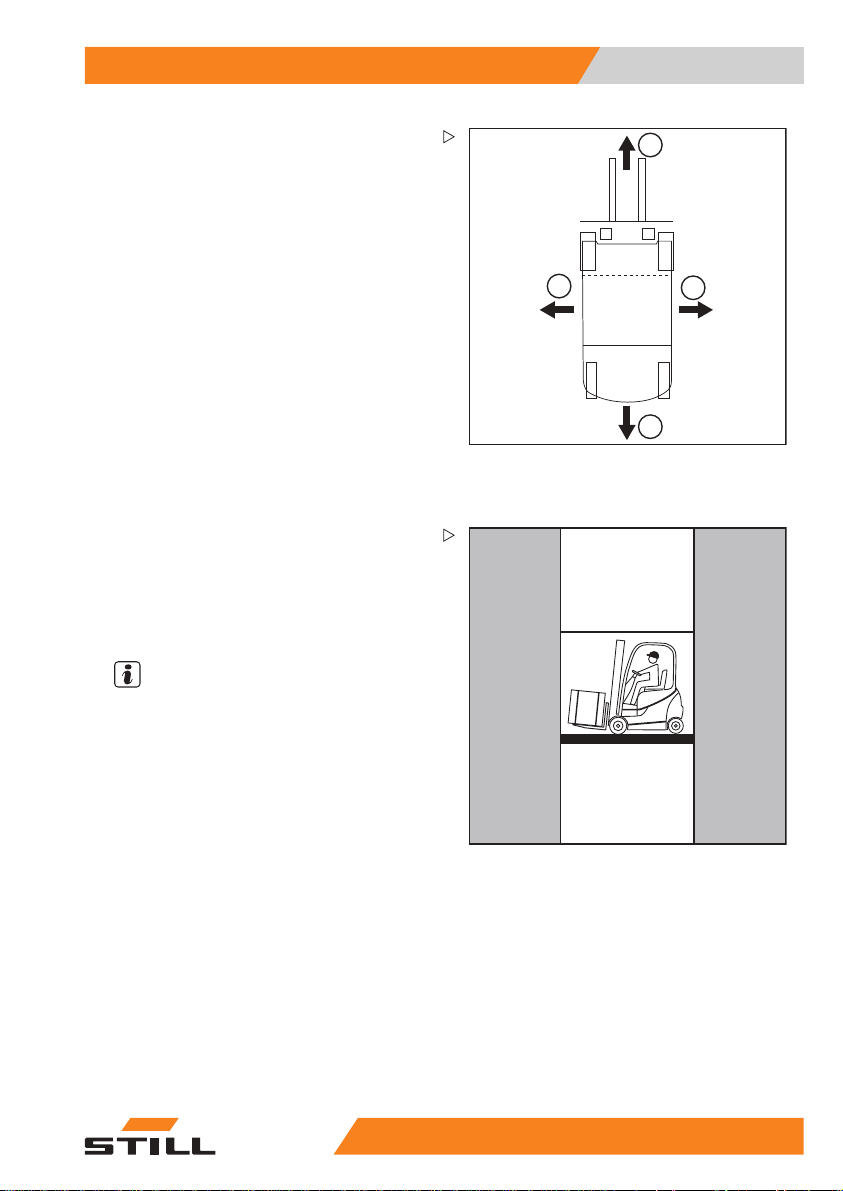
Definition of directions
The directions"forwards" (1), "backwards" (3),
"right" (2) and "left" (4) refer to the installation
position of the parts as seen from the driver’s
compartment; the load is to the front.
Schematic views
View of functions and operations
This documentati
sequential) cha
ations. Schemat
ance truck are us
dures.
NOTE
These schemati
tative of the s
truck. The dia
purpose of cla
on explains the (usually
in of certain functions or oper-
ic diagrams of a counterbal-
ed to illustrate these proce-
c diagrams are not represen-
tructural state ofthe documented
grams are used solely for the
rifying procedures.
1
4
2
3
6210_001-031
6210_003-062
048011501 EN - 12/2015 9
55
Page 22
1 Foreword
Information about documentation
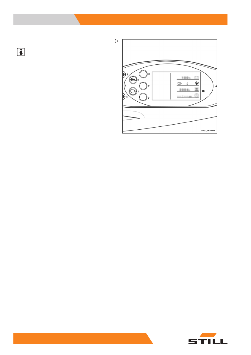
View of the display operating unit
NOTE
Views of operating statuses and values in
the display of the display operating unit are
examples and partly dependent on the truck
equipment. As a result, the displays shown
of the actual operating statuses and values
can vary. Information that is not relevant for
descriptions is not shown.
10
55048011501 EN - 12/2015
Page 23

Foreword 1
Environmental considerations
Environmental considerations
Packaging
During delivery of the truck, certain parts
are packaged to provide protection during
transport. This packaging must be removed
completely prior to initial start-up.
ENVIRONMENT NOTE
The packaging material mu
properly after delivery o
st be disposed of
f the truck.
Disposal of component
s and
batteries
The truckis composed
components or batter
and disposed of, they
• disposed of,
• treated or
• recycled in accorda
national regulatio
NOTE
The documentation provided by the battery
manufacturer must be observed when disposing of batteries.
ENVIRONMENT NOTE
We recommend working with a waste management company for disposal purposes.
of different materials. If
ies need to be replaced
must be:
nce with regional and
ns.
048011501 EN - 12/2015 11
55
Page 24

1 Foreword
Environmental considerations
12
55048011501 EN - 12/2015
Page 25

2
Introduction
Page 26

2 Introduction
Use of truck
Use of truck
Proper usage
The truck described in these operating instructions is suitable for lifting, transporting
and stacking loads.
The truck may only be used for its proper
purpose as set out and described in these
operating instructions.
If the truck is to be used for
than those specified in the o
tions, the approval of the m
applicable, the relevant r
must be obtained beforeha
ards.
The maximum load to be lifted is specified on
the capacity rating plate (load diagram) and
must not be exceeded; see also the chapter
entitled "Before picking up a load".
Proper use during towing
This truck is suitable for the occasional towing
of trailersand is equipped with a towing device
for this purpose. This occasional towing may
not exceed 2% of the daily operating time. If
the truck is to be used for towing on a more
regular basis, the manufacturer should be
consulted.
The regulations regarding trailer operation
must be observed; see chapter "Trailer
operation".
purposes other
perating instruc-
anufacturer and, if
egulatory authorities
nd to prevent haz-
Impermissible use
The operating company or driver, and not the
manufacturer, is liable for any hazards caused
by improper use.
NOTE
Please observe the definition of the following
responsible persons: "operating company"
and "driver".
Use for purposes other than those described
in these operating instructions is prohibited.
14
55048011501 EN - 12/2015
Page 27

Introduction 2
Use of truck
DANGER
There is a risk of fatal injury from
falling off the truck while it is moving!
– It is prohibited to carry passengers
on the truck.
The truck may not be operated in areas where
there is a risk of fire, explosion or corrosion, or
in areas that are particularly dusty.
Stacking or unstacking is not permissible on
inclined surfaces or ramps.
Place of use
The truck can be used both outside and in
buildings. Operation on public roads is only
permitted if the "StVZO" (German Road Traffic
Licensing Regulations) equipment variant is
installed.
If the truck is to be operated on public roads, it
must conform to the existing national regulations for the country in which it is being used.
The ground must have an adequate load
capacity (concrete, asphalt) and a rough
surface. Routes, work areas and aisle widths
must conform to the specifications in these
operating instructions, see the "Routes"
chapter.
Driving on upward and downward gradients
is permitted provided the specified data and
specifications are observed, see the "Routes
"chapter.
The forklift truck is suitable for indoor and
outdoor use in countries ranging from the
Tropics to Nordic regions (temperature range:
-20°C to +40°C).
If the truck is to be used in a cold store, it must
be configured accordingly and, if necessary,
approved for such an environment; see the
chapter entitled "Cold store application".
048011501 EN - 12/2015 15
55
Page 28
2 Introduction
Use of truck
CAUTION
Batteries can freeze!
If the truck is parked in an ambient temperature of
below –10 °C for an extended period, the batteries
cool down. The electrolyte may freeze and damage
the batteries. The truck is thennot ready for operation.
– In an ambient temperature of below –10 °C, only
park the truck for shortperiods.
The operating company must ensure suitable
fire protection for the relevant application in
the truck’s surroundings. Depending on the
application, additional fire protection must be
provided on the truck. If in doubt, contact the
relevant authorities.
NOTE
Please observe the definition of the following
responsible person: "operating company".
Parking in temperatures below -10°C
CAUTION
Batteries can freeze!
Ifthetruckisparkedinanambienttemperature
below -10°C for an extended period, the batteries
will cool down. The electrolyte may freeze and
damage the batteries. The truck is then not ready
for operation.
– When the ambienttemperature is below -10°C,
only park the truck for short periods of time.
Using working platforms
WARNING
The use of working platforms is regulated by national law. The use of working platforms is only
permitted by virtue of the jurisdiction in the country
of use.
– Observe national legislation.
– Before using working platforms, consult the
national regulatory authorities.
16
55048011501 EN - 12/2015
Page 29

Introduction 2
Residual risk
Residual risk
Residual dangers, residual risks
Despite careful working and compliance with
standards and regulations, the occurrence
of other risks when using the truck cannot be
entirely excluded.
The truck and all other system components
comply with current safety requirements.
Nevertheless, even when the truck is used
for its proper purpose and all instructions
are followed, some residual risk cannot be
excluded.
Even beyond the narrow dan
truck itself, a residual r
Persons in this area aroun
exercise a heightened deg
so that they can react imme
of any malfunction, incid
WARNING
All persons that are in the vicinity of the truck
must be instructed regarding these risks that arise
through use of the truck.
In addition,we draw attention to the safety regulations in these operating instructions.
ger areas of the
isk cannot be excluded.
d the truck must
ree of awareness,
diately in the event
ent or breakdown etc.
The risks can include:
• Escape of consumables due to leakages,
rupture of lines and containers etc.
• Risk of accident when driving over difficult
ground such as gradients, smooth or
irregular surfaces, or with poor visibility
etc.
• Falling, tripping etc. when moving on
the truck, especially in wet weather, with
leaking consumables or on icy surfaces
• Fire and explosion risks dueto batteries and
electrical voltages
• Human error resulting from failure to
observe the safety regulations,
• Unrepaired damage or defective and worn
components,
• Insufficient maintenance and testing
• Use of incorrect consumables
• Exceeding test intervals
048011501 EN - 12/2015 17
55
Page 30

2 Introduction
Residual risk
The manufacturer is not held responsible for
accidents involving the truck caused by the
failure of the operating company to comply
with these regulations either intentionally or
carelessly.
Stability
The stability of the truck has been tested to the
latest technological standards and is guaranteed provided that the truck is used properly
and according to its intended purpose. These
standards only take into account the dynamic
and static tipping forces that can arise during
specified use in accordance with the operating rules and intended purpose. However, the
danger of exceeding the moment of tilt due to
improper use or incorrect operation and losing
stability can never be excluded.
The loss of stability can b
imised by the following ac
– Always secure the load against slipping,
e.g. by lashing.
– Always transport unstable loads in suitable
containers.
– Always drive slowly whe
– Drive with the load lowered.
– Even with sideshifts, align the load as
centrally as possible with the truck and
transport in this position.
– Avoid turning and dia
slopes or gradients.
– Never have the load facing downhill when
travelling on slopes or gradients.
– Pick up only loads of the approved width.
– Always take great ca
swinging loads.
– Do not drive over ramp edges or steps.
e avoided or min-
tions:
n cornering.
gonally driving across
re when transporting
Special risks associated with using the truck and attachments
Approval from the manufacturer and attachment manufacturer must be obtained each
18
55048011501 EN - 12/2015
Page 31

Introduction 2
Residual risk
time the truck is used in a manner that falls
outside the scope of normal use, and in cases
where the driver is not certain that he can use
the truck correctly and without the risk of accidents.
048011501 EN - 12/2015 19
55
Page 32

2 Introduction
Residual risk
Overview of hazards and countermeasures
NOTE
This table is intended to help evaluate the
hazards in your facility and applies to all drive
types. It does not claim to be complete.
– Observe the national regulations for the
country in which the truck is being used.
Hazard Measure
Truck equipment does
not comply with local
regulations
Lack of skills and
qualification of driver
Usage by unauthorised persons
Truck not in a safe
condition
Risk of falling when
using working
platforms
Impaired visibility due
to load
Contamination of
respiratory air
Test
Driver training (sit-on
and stand-on)
Access with key only
for authorised persons
Recurrent testing and
rectification of defects
Compliance with
national regulations
(different national
laws)
Resource planning
Assessment of diesel
exhaust gases
Assessment of LPG
exhaust gases
Check note
√ Complete
- Not applicable
O If in doubt, consult
O BGG 925
O
O German Ordinance on
O German Ordinance on
O German Ordinance on
O
O German threshold
Notes
competent factory
inspectorate or
employers’ liability
insurance association
VDI 3313 driver permit
Industrial Safety and
Health (BetrSichV)
Industrial Safety and
Health (BetrSichV)
and employer’s
liability insurance
associations
Industrial Safety and
Health (BetrSichV)
Technical Regulations
for Hazardous
Substances (TRGS)
554 and the German
Ordinance on
Industrial Safety and
Health (BetrSichV)
limit values list
(MAK-Liste) and the
German Ordinance on
Industrial Safety and
Health (BetrSichV)
20
55048011501 EN - 12/2015
Page 33

Introduction 2
Residual risk
Hazard Measure
Impermissible usage
(improper usage)
When fuelling
a) Diesel Note the German
b) LPG Note German Social
Issuing of operating
instructions
Written notice of
instruction to driver
Note the German
Ordinance on
Industrial Safety and
Health (BetrSichV),
the operating
instructions and the
German Engineering
Federation (VDMA)
rules
Ordinance on
Industrial Safety and
Health (BetrSichV),
the operating
instructions and the
German Engineering
Federation (VDMA)
rules
Accident Insurance
(DGUV) regulation
D34, the operating
instructions and the
German Engineering
Federation (VDMA)
rules
Check note
√ Complete
- Not applicable
O German Ordinance on
O German Ordinance on
O
O
O
Notes
Industrial Safety and
Health (BetrSichV)
and German Health
and labour protection
law (ArbSchG)
Industrial Safety and
Health (BetrSichV)
and German Health
and labour protection
law (ArbSchG)
048011501 EN - 12/2015 21
55
Page 34

2 Introduction
Residual risk
Hazard Measure
When charging the
traction battery
When using battery
chargers
When parking LPG
trucks
With driverless transport systems
Roadway quality
inadequate
Load carrier
incorrect/slipped
Drive behaviour
unpredictable
Driveways blocked Mark driveways
Note the German
Ordinance on
Industrial Safety and
Health (BetrSichV),
the operating
instructions and the
German Engineering
Federation (VDMA)
rules
Note the German
Ordinance on
Industrial Safety and
Health (BetrSichV),
employers’ liability
insurance association
regulation 104 and the
operating instructions
Note the German
Ordinance on
Industrial Safety and
Health (BetrSichV),
employers’ liability
insurance association
regulation 104 and the
operating instructions
Clean/clear driveways O German Ordinance on
Reattach load to pallet
Employee training
Keep driveways clear
Check note
√ Complete
- Not applicable
O Association for
O German Ordinance on
O German Ordinance on
O German Ordinance on
O German Ordinance on
O German Ordinance on
Notes
Electrical, Electronic
and Information
Technologies (VDE)
regulation 0510: In
particular
- Ensure adequate
ventilation
- Insulation value
within the permissible
range
Industrial Safety and
Health (BetrSichV)
and employers’
liability insurance
association regulation
104
Industrial Safety and
Health (BetrSichV)
and employers’
liability insurance
association regulation
104
Industrial Safety and
Health (BetrSichV)
Industrial Safety and
Health (BetrSichV)
Industrial Safety and
Health (BetrSichV)
Industrial Safety and
Health (BetrSichV)
22
55048011501 EN - 12/2015
Page 35

Introduction 2
Residual risk
Hazard Measure
Driveways intersect
Announce right-ofway rule
No person detection
Employee training
during depositing and
retrieval
.
Danger to employees
According to the German Ordinance on Industrial Safety and Health (BetrSichV) and labour
protection law (ArbSchG), the operating company must determine and assess hazards
during operation, and establish the labour
protection measures required for employees (BetrSichVO). The operating company
must therefore draw up appropriate operating
instructions (§ 6 ArbSchG) and make them
available to the driver. A responsible person
must be appointed.
NOTE
Please observe t
responsible per
and "driver".
The construction and equipment of the
truck correspond to the Machinery Directive
2006/42/EC and are therefore marked with
CE labelling. These elements are therefore
not included in the hazard assessment. Attachments possess their own CE labelling and
likewise are not included for that reason. The
operating company must, however, select the
type and equipment of thetrucks so as to comply with the local provisions for deployment.
The result must be documented (§ 6 ArbSchG). In the case of truck applications involving similar hazard situations, the results may
be summarised. This overview (see chapter
"Overview of hazards and countermeasures")
provides help on complying with this regulation. The overview specifies the main hazards
that are the most frequent cause of accidents
in the event of non-compliance. If other major
he definition of the following
sons: "operating company"
Check note
√ Complete
- Not applicable
O German Ordinance on
O German Ordinance on
Notes
Industrial Safety and
Health (BetrSichV)
Industrial Safety and
Health (BetrSichV)
048011501 EN - 12/2015 23
55
Page 36

2 Introduction
Residual risk
operational hazards are involved, they must
also be taken into consideration.
The conditions of use for trucks are broadly
similar in many plants, so the hazards can
be summarised in one overview. Observe
the information provided by the relevant
employers’ liability insurance association on
this subject.
24
55048011501 EN - 12/2015
Page 37

3
Safety
Page 38

3 Safety
Definition of responsible persons
Definition of responsible persons
Operating company
The operating company is the natural or legal
person or group who operates the truck or on
whose authority the truck is used.
The operating company must ensure that the
truck is only used for its proper purpose and in
compliance with the safety regulations set out
in these operating instructions.
The operating company must
all users read and understa
information.
The operating company is responsible for the
scheduling andcorrect performance of regular
safety checks.
We recommend that the national performance
specifications are adhered to.
Specialist
A qualified person is defined as a service
engineer or a person who fulfils the following
requirements:
• A completed vocation
demonstrably proves
expertise. This proo
a vocational qualifi
document.
• Professional experience indicating that
the qualified person has gained practical
experience of industrial trucks over a
proven period during their career During
this time, this person has become familiar
with a wide range of symptoms that require
checks to be carried out, such as based
on the results of a hazard assessment or a
daily inspection
• Recent professional involvement in the
field of the industrial truck test in question
and an appropriate further qualification
are essential. The qualified person must
have experience of carrying out the test
in question or of carrying out similar tests.
Moreover, this person must be aware of
the latest technological developments
cation or a similar
ensure that
nd the safety
al qualification that
their professional
f should consist of
26
55048011501 EN - 12/2015
Page 39

Safety 3
Definition of responsible persons
regarding the industrial truck to be tested
and the risk being assessed
Drivers
This truck may only be driven by suitable persons who are at least 18 years of age, have
been trained in driving, have demonstrated
their skills in driving and handling loads to
the operating company or an authorised representative, and have been specifically instructed to drive the truck. Specific knowledge
of the truck to be operated is also required.
The training requirements under §3 of the
Health and Safety at Work Act and §9 of the
plant safety regulations are deemed to have
been satisfied if the driver has been trained in
accordance with BGG (General Employers’
Liability Insurance Association Act) 925.
Observe the national regulations for your
country.
Driver rights, duties and rules of behaviour
The driver must be trai
duties.
The drivermust be grantedthe required rights.
The driver must wear protective equipment
(protection suit, safety footwear, safety
helmet, industrial goggles and gloves) that
is appropriate for the conditions, the job and
the load to be lifted. Solid footwear should be
worn to ensure safe driving and braking.
Thedrivermustbefa
instructions and ha
times.
The driver must:
• have read and understood the operating
manual
• have familiarised himself with safe operation of the truck
• be physically and m
truck safely
ned in his rights and
miliar with the operating
ve access to them at all
entally able to drive the
048011501 EN - 12/2015 27
55
Page 40

3 Safety
Definition of responsible persons
DANGER
The use of drugs, alcohol or medicationsthat affect
reactions impair the ability to drive the truck!
Individuals under the influence of the aforementioned substancesare not permitted to perform work
of any kind on or with the truck.
Prohibition of use by unauthorised
persons
The driver is responsible for the truck during
working hours. He must not allow unauthorised persons to operate the truck.
When leavingthe truck, thedriver must secure
it against unauthorised use, e.g. by pulling out
the key.
28
55048011501 EN - 12/2015
Page 41

Safety 3
Essentials for safe operation
Essentials for safe operation
Insurance cover on company premises
In many cases, company premises are
restricted public traffic areas.
NOTE
The business liability insurance should be
reviewed to ensure that, in the event of any
damage caused in restricted public traffic
areas, there is insurance cover for the truck in
respect of third parties.
Changes and retrofitting
If the truck is used for work that is not listed
in the guidelines or in these instructions and
has to be converted or retrofitted accordingly,
you must note that any change to its structural
state can affect the handling and stability of
the truck, which in turn can lead to accidents.
You should therefor
centre beforehand.
Changes that will adversely affect stability,
load capacity and safety systems, among
other things, must not be made without the
manufacturer’s approval.
The truck can only be converted with written
approval from the manufacturer. Approval
from the responsible authority must be obtained if necessary.
Changes to the bra
elements, circum
variants (e.g. at
made without the p
manufacturer.
We warn against the installation and use
of restraint systems not approved by the
manufacturer.
e contact your service
kes, steering, control
ferential view, equipment
tachments) must also not be
rior written approval of the
048011501 EN - 12/2015 29
55
Page 42

3 Safety
Essentials for safe operation
DANGER
Risk ofinjury if truck tips over!
Even when using an approved
restraint system, there is some
residual risk that the driver might
be injured if the truck tips over. This
risk of injury can be reduced through
the combined use of a restraint
system and the seat belt. In addition,
the seat belt protects against the
consequences of rear-end collisions
and fallingoff a ramp.
– Use the seat belt too.
When carrying out welding work on the
truck, it is essential that the battery and all
connections to the electronic control cards are
disconnected. Contact the authorised service
centre on this matter.
DANGER
Risk of explosion from additional
holes in the battery hood!
Explosive gases can escape and
lead to potentially fatal injuries if they
explode. Sealing holes with plugs
is not sufficient to prevent gas from
escaping.
– Do not drill any holesin the battery
hood.
DANGER
Risk of accident from additional holes in the battery
hood!
The rigidity of the battery hood is impaired and
the battery hood may fracture. The driver’s seat
may collapse, leading to a risk of accident due to
uncontrolled steering movements whilstdriving.
– Do not drill any holes in the battery hood.
30
55048011501 EN - 12/2015
Page 43

Safety 3
Essentials for safe operation
DANGER
Risk to life from falling load!
If the truck is not equipped with an overhead guard,
there is a risk to the driver’s life, as he may be struck
by a load falling from a lift height of 1800 mm or
greater.
Operation of the truck without an overhead guard at
a lift height of over 1800 mm is prohibited.
– For lift heights of 1800 mm and above, only use
trucks withan overhead guard.
In the event of the manufacturer going into
liquidation and the company not being taken
over by another legal person, the operating
company can make changes to the truck.
To do so, the operating company must fulfil
the following prerequisites:
Construction documents, test documents
and assembly instructions associated with
the change must be archived and remain
accessible at all times.
Check that the capacity rating plate, decal information, hazard warnings and the operating
instructions are consistent with regard to the
changes and modify if necessary.
The change must be designed, checked
and implemented by a design office that
specialises in industrial trucks in accordance
with the standards and directives valid at the
time the changes are made.
Decal information with the following data must
be permanently affixed to the truck so it is
clearly visible:
– Type of change
– Date of change
– Name and address of the company imple-
menting the change.
048011501 EN - 12/2015 31
55
Page 44

3 Safety
Essentials for safe operation
Changes to the overhead guard and roof loads
DANGER
In the event of the overhead guard failing due to
a falling load or the truck tipping over, there are
potentially fatal consequences for the driver. There
is a risk to life!
Welding and drilling on the overhead guard changes the material characteristics and the structural
design of the overhead guard. Excessive forces
caused by falling loads orthe trucktipping over may
result in buckling of the modified overhead guard
andnoprotectionforthedriver.
– Do not perform welding on the overhead guard.
– Do not perform drilling on the overhead guard.
CAUTION
Heavy roof loads damage the overhead guard!
To ensure the stability of the overhead guard at
all times, a roof load may only be mounted on the
overhead guard if the structural design has been
tested and the manufacturerhas given approval.
– Seek advice from the authorised service centre
for the mounting of roof loads.
Warning regardingnon-original parts
Original parts, attachments and accessories
are specially designed for this truck. We
specifically draw your attention to the fact that
parts, attachments and accessories supplied
by other companies have not been tested and
approved by STILL.
CAUTION
Installation and/or use ofsuch products may therefore have a negative impact on the design features
of the truck and thus impair active and/or passive
driving safety.
We recommend that you obtain approval from the
manufacturer and, if necessary, from the relevant
regulatory authorities before installing such parts.
The manufacturer accepts no liability for any damage caused by the use of non-original parts and
accessories without approval.
32
55048011501 EN - 12/2015
Page 45

Safety 3
Essentials for safe operation
Damage, defects and misuse of safety systems
Damage or other defects on the truck or
attachment must be reported to the supervisor
or responsible fleet manager immediately so
that they can have the defect rectified.
Trucks andattachments that are not functional
or safe to drivemay not be used until they have
been properly repaired.
Do not remove or deactivate
and switches.
Fixed set valuesmay only be changed withthe
approval of the manufacturer.
Work onthe electrical system (e.g. connecting
a radio, additional headlights etc.) is only
permitted with the manufacturer’s written
approval. All electrical system interventions
must be documented.
Even if they are removabl
not be removed, as they a
protect against small f
safety systems
e, roof panels may
re designed to
alling objects.
Tyres
DANGER
Risk to stability!
Failure to observe the following information and
instructions can lead to a loss of stability. The truck
may tip over, risk of accident!
Thefollowingfactorscanleadtoalossof
stability and are therefore prohibited:
• Different tyres on the same axle, e.g.
pneumatic tyres and superelastic tyres
• Tyres not approved by the manufacturer
• Excessive tyre wear
• Tyres of inferior quality
• Changing rim wheel parts
• Combining rim wheel parts from different
manufacturers
048011501 EN - 12/2015 33
55
Page 46

3 Safety
Essentials for safe operation
The following rules must be observed to
ensure stability:
• Only use tyres with equal and permitted
levels of wear on the same axle
• Only use wheels and tyres of the
on the same axle, e.g. only supe
tyres
• Only use wheels and tyres approved by the
manufacturer
• Only use high-quality products
Wheels and tyres approved by
facturer can be found on the s
If other wheels or tyres are t
thorisation from the manu
obtained beforehand.
– Contact the authorised service centre on
this matter.
When changing wheels or tyres, always
ensure that this does not cause the truck to
tilt to one side (e.g. always replace righthand and left-hand wheels at the same
time). Changes must only be made following
consultation with the manufacturer.
Ifthetypeoftyreusedon
for example from superel
matic tyres, the load dia
accordingly.
– Contact the authorised service centre on
this matter.
facturer must be
an axle is changed,
astic tyres to pneu-
gram must be changed
same type
relastic
the manu-
pare parts list.
o be used, au-
Medical equipment
WARNING
Electromagneticinterference may occuron medical
devices!
Only use equipment that is sufficiently protected
against electromagnetic interference.
Medical equipment, such as pacemakers or
hearing aids, may not work properly when the
truck is in operation.
– Ask your doctor or the manufacturer of
the medical equipment to confirm that the
medical equipment is sufficiently protected
against electromagnetic interference.
34
55048011501 EN - 12/2015
Page 47

Safety 3
Essentials for safe operation
Exercise caution when handling gas springs and accumulators
WARNING
Gas springs are under high pressure. Improper
removal resultsin an elevated risk of injury.
For ease of operation, various functions on the
truck can be supported by gas springs. Gas springs
are complex components that are subject to high
internal pressures (up to 300 bar). They may under
no circumstances be opened unless instructed to
do so, and may be installed only when not under
pressure. If required, the authorised service centre
will depressurise the gas spring in accordancewith
the regulations before removal. Gas springs must
be depressurisedbefore recycling.
– Avoid damage, lateral forces, buckling, tempe-
ratures over80°C and heavy contamination.
– Damaged or defective gas springs must be
changed immediately.
– Contact the authorised service centre.
WARNING
Accumulators are under high pressure. Improper
installation of an accumulator results in an elevated
risk of injury.
Before starting work on the accumulator it must be
depressurised.
– Contact the authorised service centre.
Length of the fork arms
DANGER
Risk of accident due to the incorrect selection of
fork arms!
– The fork arms must match the depth of the load.
If the fork arms are too short, the load may
fall off the arms after it has been picked up.
In addition, be aware that the load centre of
gravity may shiftas a result of dynamic forces,
such as braking. A load that is otherwise
resting safely on the fork arms may move
forwards and fall.
If the fork arms are too long, they can catch
on loading units behind the load that is to be
048011501 EN - 12/2015 35
55
Page 48

3 Safety
Essentials for safe operation
picked up. These other loading units then fall
over when the load is raised.
– For help with selecting the correct fork arms,
contact the authorised service centre.
36
55048011501 EN - 12/2015
Page 49

Safety 3
Safety tests
Safety tests
Regular safety inspection of the truck
Safetyinspectionbasedontimeand
extraordinary incidents
The operating company must ensure that the
truck is checked by a specialist at least once a
year or after particular incidents.
As part of this inspection
of the technical conditio
performed with regard to a
In addition, the truck mus
checked for damage that co
have been caused by impro
log must be created. The r
inspection must be retai
inspections have been ca
The inspection date is indicated by an adhesive label on the truck.
– Arrange for the service centre to perform
periodic safety inspections on the truck.
– Observe guidelines fo
on the truck in accorda
The operator is responsible for ensuring any
defects are remedied without delay.
– Contact your service centre.
, a complete check
n of the truck must be
ccident safety.
t be thoroughly
uld potentially
per use. A test
esults from the
ned until a further two
rried out.
r checks carried out
nce with FEM 4.004.
NOTE
Observe the national regulations for your
country!
Insulation testing
The truck insulation must have sufficient insulation resistance. For this reason, insulation
testing in accordance with DIN EN 1175 and
DIN 43539, VDE 0117 and VDE 0510 must be
conducted at least once a year.
NOTE
The truck’s el
ries must be ch
ectrical system and drive batte-
ecked separately.
048011501 EN - 12/2015 37
55
Page 50

3 Safety
Safety tests
Measuring the battery’s insulation
resistance
NOTE
Nominal battery voltage < test voltage < 500
V.
– Measure the insulation resistance with a
suitable measuring device.
The insulation resistance can be considered
sufficient if it measures at least 500
nominal battery voltage against ground.
– Contact the authorised service centre.
Measuring the insulation resistance of
the electrical system
NOTE
Nominal battery voltage < test voltage < 500
V.
– Ensure that all volt
disconnected from t
– Measure the insulation resistance with a
suitable measuring device.
The insulation resistance can be considered
sufficient if it measures at least 1000
the nominal battery voltage against ground.
– Contact the author
age sources have been
he circuit to be tested.
ised service centre.
/V for the
/V for
38
55048011501 EN - 12/2015
Page 51

Safety 3
Safety regulations for handling co
nsumables
Safety regulations for handling consumables
Permissible consumables
DANGER
Failure to observe the safety regulations relatingto
consumables mayresult in a risk of injury, death or
damage to the environment.
– Observe the safety regulations when handling
such materials.
Refer to the maintenance data table for the
permissible substances that are necessary for
operation (see ⇒ Chapter "Maintenance data
table", P. 6-303).
Oils
DANGER
Oils are flammable!
– Follow the statutory regulations.
– Donotallowoilstocomeinto
contact with hot engine parts.
– No smoking,fires ornaked flames!
DANGER
Oils are toxic!
– Avoid contact and consumption.
– If vapour or fumes are inhaled,
move to fresh air immediately.
– In the event of contact with the
eyes, rinsethoroughly (for at least
10 minutes) with water and then
consult an eye specialist.
– If swallowed, do not induce
vomiting. Seek immediate medical
attention.
048011501 EN - 12/2015 39
55
Page 52

3 Safety
Safety regulations for handling co
WARNING
Prolonged intensive contact with the
skin can result in dryness and irritate
the skin!
– Avoid contact and consumption.
– Wear protective gloves.
– After any contact, wash the skin
with soap and water, and then
apply a skin care product.
– Immediately change soaked
clothing and shoes.
WARNING
There is a risk of slipping on spilled oil, particularly
when combined with water!
– Spilt oil should be removed immediately with
oil-binding agents and disposed of according to
the regulations.
ENVIRONMENT NOTE
Oil is a water-polluting substance!
•
Always store oil in containers that comply
with the applicable regulations.
•
Avoid spilling oils.
•
Spilt oil should be removed immediately
with oil-binding agents and disposed of
according to the regulations.
•
Dispose of old oils according to the regulations.
nsumables
Hydraulic fluid
These fluids are pressurised during
operation of the truck and are
hazardous to your health.
– Do not spill the fluids.
– Follow the statutory regulations.
– Do not allow the fluids to come into
contact withhot engine parts.
40
WARNING
55048011501 EN - 12/2015
Page 53

Safety 3
nsumables
WARNING
These fluids are pressurised during
operation of the truck and are
hazardous to your health.
– Do not allow the fluids to come into
contact with the skin.
– Avoid inhaling spray.
– Penetration of pressurised
fluids into the skin is particularly
dangerous if these fluids escape
at high pressure due to leaks in
the hydraulic system. In case of
such injury, immediate medical
assistance is required.
– To avoid injury, use appropriate
personal protective equipment
(e.g. protective gloves, industrial
goggles, skin protection and skin
care products).
ENVIRONMENT NOTE
Safety regulations for handling co
Hydraulic fluid is a water-polluting substance.
•
Always store hydraulic fluid in containers
that comply with regulations
•
Avoid spills
•
Spilt hydraulic fluid should be removed
immediately with oil-binding agents and
disposed of according to the regulations
•
Dispose of old hydraulic fluid according to
the regulations
Battery acid
Battery acid contains dissolved
sulphuric acid. This is toxic.
– Avoid touching or swallowing the
– In case of injury, seek medical
WARNING
battery acid at all costs.
advice immediately.
048011501 EN - 12/2015 41
55
Page 54

3 Safety
Safety regulations for handling co
WARNING
Battery acid contains dissolved
sulphuric acid. This is corrosive.
– When working with battery acid,
always wear a protection suit and
eye protection.
– When working with battery
acid, never wear a watch or any
jewellery.
– Do not allow any acid to get
onto clothing or skin or into the
eyes; if this does happen, rinse
immediately with plenty of clean
water.
– In case of injury, seek medical
advice immediately.
– Immediately rinse away spilt
battery acid with plenty of water.
– Follow the statutory regulations.
ENVIRONMENT NOTE
– Dispose of used battery acid in line with the
applicable regulations.
Brake fluid
nsumables
WARNING
Brake fluid is poisonous!
– Avoid swallowing. In the event
of swallowing, do not induce
vomiting. Rinse out your mouth
thoroughly with water and ask a
doctor for advice.
– Avoid aerosolisation and inha-
lation. In the event of inhalation,
seek freshair. Ask a doctor for advice if necessary.
42
55048011501 EN - 12/2015
Page 55

Safety 3
nsumables
WARNING
Brake fluid is hazardous to your
health!
Brake fluid irritates the eyes and
can dry out the skin upon prolonged
contact.
– Coat your hands with a protective
skincreampriortostartingwork.
– Avoid prolonged or intensive
skin contact. In the event of skin
contact, cleanthe wetted skin with
water and soap, and subsequently
apply a skin care product.
– Prevent contact with the eyes. In
the event of contact with the eyes,
wash out the affected eye(s) with
clean water for ten minutes and
then aska doctor for advice.
– Change clothing soiled with brake
fluid as soon as possible.
CAUTION
Brake fluid is flammable!
– Do not allow brake fluid to come into contact with
hot motor parts.
– Smoking, fires and naked flamesare prohibited.
Safety regulations for handling co
CAUTION
Brake fluid has strong dissolvingand colour-changing properties.
– Immediately rinse off any brake fluid that has
splashed on paint, clothing, and shoes with
plenty of water
ENVIRONMENT NOTE
Brake fluid is a water pollutant!
•
Always store brake fluid in containers
complying with the regulations..
•
Do not spill brake fluid.
•
Spilt brake fluid must be removed immediately using an oil binding agent and disposed
of in accordance with regulations
•
Dispose of old brake fluid according to the
regulations.
•
Observe the national regulations for the
country in which the truck is being used.
048011501 EN - 12/2015 43
55
Page 56

3 Safety
Safety regulations for handling co
Disposal of consumables
ENVIRONMENT NOTE
Materials that accumulate during repair,
maintenance and cleaning must be collected
properly and disposed of in accordance with
the national regulations for the country in
which the truck is being used. Work must
only be carried out in areas designated for the
purpose. Care must be taken to minimise any
environmental pollution.
– Soak up any spilt fluids such as hydraulic
oil, brake fluid or gearbox oil using an
oil-binding agent.
– Neutralise any spilt bat
ately.
– Always observe national regulations con-
cerning the disposal of used oil.
tery acid immedi-
nsumables
44
55048011501 EN - 12/2015
Page 57

Safety 3
Emissions
Emissions
The values specified apply to a standard truck
(compare the specifications in the "Technical
data" chapter). Different tyres, lift masts,
additional units etc. may produce different
values.
Noise emissions
The values were determined based on
measuring procedures from the standard
EN 12053 "Safety of industrial trucks. Test
methods for measuring noise emissions",
based on EN 12001 and EN ISO 3744 and the
requirements of EN ISO 4871.
L
pAZ
lowing sound
This machine emits the fol
pressure levels:
Continuous sound pressure level in the
driver’s compartment
< 70 dB(A)
The values were determ
on an identical machin
values for operating s
Time proportions:
• Lifting 18%
• Idling 58%
• Driving 24%
However, the indicated noise levels at the
truck cannot be used to determine the noise
emissions at workplaces according tothe most
recent version of Directive 2003/10/EC (daily
personal noise pollution). If required, these
noise emissions must be determined directly
at the workplaces under the actual conditions
present (further sources of noise, particular
application conditions, sound reflections) by
the operating company.
NOTE
Please observe th
responsible per
son: "operating company".
ined in the test cycle
e from the weighted
tatuses and idling.
e definition of the following
048011501 EN - 12/2015 45
55
Page 58

3 Safety
Emissions
Vibrations
The vibrations of the machine have been
determined on an identical machine in accordance with the standards DIN EN 13059
"Safety of industrial trucks - Test methods
for measuring vibration" and DIN EN 12096
"Mechanical vibration - Declaration and verification of vibration emission values".
Frequency-weighted effective value of acceleration on the seat
MSG 65 driver’s seat
0.68 m/s
Tests have indicated that the amplitude of the
hand and arm vibrations on the steering wheel
or the operating devices in trucks is less than
2.5 m/s
ment guidelines for these measurements.
The individual vibrati
over the course of a work
determined by the oper
accordance with Direc
the actual place of use
additional influences
intensity of use etc.
2
2
. There are therefore no measure-
Measurement
uncertainty
0.204 m/s
on load on the driver
ing day must be
ating company in
tive 2002/44/EC at
in order to consider all
, such as driving route,
2
NOTE
Please observe the definition of the following
responsible person: "operating company".
46
55048011501 EN - 12/2015
Page 59

Safety 3
Emissions
Battery
DANGER
Risk of explosion due to flammable
gases!
During charging, the batteryreleases
a mixture of oxygen and hydrogen
(oxyhydrogen gas). This gas mixture
is explosive and must not be ignited.
– Make sure that there is always
sufficient ventilation in working
areas that are entirely or partially
enclosed.
– Keep away from open flames and
flying sparks
– Do not smoke.
– Observe the safety regulations for
handling the battery.
048011501 EN - 12/2015 47
55
Page 60

3 Safety
Emissions
48
55048011501 EN - 12/2015
Page 61

4
Overviews
Page 62

4 Overviews
General view of truck
General view of truck
1
2
12
3
11
10
9
1Liftmast
2 Overhead guard
3 Driver’s compartment
4 Battery door
5 Battery hood
6 Connection for towing bracket / towcoupling
(optional)
8
7 Drive wheel
8 Right-hand bottomplate
9 Left-hand bottomplate
10 Running axle
11 Fork arms
12 Lift cylinder
4
5
5060_003-094_V2
6
7
50
55048011501 EN - 12/2015
Page 63

Overviews 4
General view of truck
048011501 EN - 12/2015 51
55
Page 64

4 Overviews
4
General view of driver’s compartme
nt
General view of driver’s compartment
15
14
13
1
34
2
5
6
7
8
9
5060_003-093_V2
12
1 Parking brake lever
2 Steering wheel
3Switchkey
4 Display operating unit
5 Document holder and storage location for
operating instructions
6 Operating devices for hydraulic and traction
functions
7 Emergency stop switch (only in multiple-
lever version)
52
11
55048011501 EN - 12/2015
10
8 Storage box
9 Cup holder for bottles max. 1 l
10 Battery hood handle
11 Battery hood release
12 Driver’s seat
13 Accelerator pedal
14 Brake pedal
15 Signal horn foot switch
Page 65

Overviews 4
Operating devices and display elem
ents
Operating devices and display elements
Display and operating unit
2
1
26
25
5060_003-087
1 Hazard warni
2 Front winds
3 Front worki
4 Drive prog
5 Rear work
6 Rear wor
7 Not ass
8 Batte
9Drive
10 Left
11 For
12 Rig
13 Ma
24
ram selectorbutton
ing spotlightbutton
king spotlight symbol
igned
ry charge display (percent)
programme display (numerical)
direction indicator light
ward travel display
ht direction indicator light
lfunction display
4
3
3
1
2
5
22
23
ng system button
creen wiper button
ng spotlight button
56
8
6
9
7
0
20
21
19
7
75
%
2
90°
12:15
17
18
14 Reverse trav
15 Steering po
16 Time displa
17 Not assign
18 Rotating
19 Not assi
20 Not ass
21 Not as
22 Not as
23 Menu
24 Lig
25 Blu
26 Re
gned
igned
signed
signed
change button
hting button
e-Q button
ar window wiper button
8
9
15
16
el display
sition display (degrees)
y (digital)
ed
beacon display
10
11
12
13
14
NOTE
The buttons (5, 21, 22) and the corresponding
indicators (6, 7, 18, 19, 20) are assigned
according to the auxiliary equipment installed.
The assignment shown here is an example
and may differ from the assignment actually
programmed on the truck. Buttons may be
assigned multiple functions that are called up
according to the menu navigation. For further
information, see the "Operating the display
and operating unit" chapter.
048011501 EN - 12/2015 53
55
Page 66

4 Overviews
Operating devices and display elem
– If you have any questions, please contact
your authorised service centre.
ents
54
55048011501 EN - 12/2015
Page 67

Overviews 4
Operating devices and display elem
ents
Operating devices for hydraulic and traction functions
Different versions of the operating devices are
available for operating the truck’s hydraulic
and traction functions.
The truck can be equipped with the following
operating devices:
• Multiple-lever
• Double mini-lever
• Triple mini-lever
• Quadruple mini-lever
• Joystick 4Plus
• Fingertip
• Mini-console
048011501 EN - 12/2015 55
55
Page 68

4 Overviews
Operating devices and display elem
Multi-lever
ents
123
6
1 "Lift/lower" operating lever
2 "Tilt" operating lever
3 Operating lever for attachment(variant)
4
5
5060_003-168
4 Operating lever for attachment (variant)
5 "5th function"function switch (variant)
6 Drive direction switch
NOTE
In the dual-pedal version (variant), the truck is
equipped with a signal horn button instead of
the drive direction switch.
56
55048011501 EN - 12/2015
Page 69

Overviews 4
Operating devices and display elem
ents
Double mini-lever
3
2
1
8
1 "Lift mast" 360° lever
2 Function key F1
3 Function key F2
4 "Drive direction / turnindicator" crosslever
4
F1
F2
7312_003-002
5 Function key "5th function"
6 "Attachments" cross lever
7 Emergency stop switch
8 Signal horn button
5
6
7
NOTE
Depending on the specification, various
electric attachment parts can be controlled
via function keys (2) and (3). Changes must
only be made by the authorised servicecentre.
048011501 EN - 12/2015 57
55
Page 70

4 Overviews
Operating devices and display elem
Three-way mini-lever
ents
3
2
1
9
1 "Lift mast" 360° lever
2 Function key F1
3 Function key F2
4 "Drive direction/ turn indicator" cross lever
5 Function key "5th function"
NOTE
Depending on the specification, various
electric attachment parts can be controlled
via function keys (2) and (3). Changes must
only be made bythe authorised service centre.
4
5
6
7
5060_003-089
6 "Auxiliary hydraulics 1" operating lever
7 "Auxiliary hydraulics 2" operating lever
8 Emergency stop switch
9 Signal horn button
8
58
55048011501 EN - 12/2015
Page 71

Overviews 4
Operating devices and display elem
ents
Four-way mini-lever
4
3
2
1
10
1 "Lift/lower"
2 "Tilt" opera
3 Function ke
4 Function k
5 "Drive dir
NOTE
Depending on the specification, various
electric attachment parts can be controlled
via function keys (3) and (4). Changes must
only be made by the authorised servicecentre.
operating lever
ting lever
yF1
ey F2
ection / turn indicator"cross lever
5
6
5060_003-088
6 Function key "
7 "Auxiliary h
8 "Auxiliary
9 Emergency
10 Signal hor
ydraulics 1" operating lever
hydraulics 2" operating lever
n button
7
8
9
5th function"
stop switch
048011501 EN - 12/2015 59
55
Page 72

4 Overviews
Operating devices and display elem
Joystick 4Plus
ents
9
1
8
7
6
5
1 Horizontal rocker button for "3rd hydraulic
function", tilt the lift mast
2 Pictograms for the basic hydraulic functions
3 Pictograms for the5th hydraulic functionand
the clamp locking mechanism (variant)
4 Pictograms for the 3rd & 4th hydraulic
functions
2
3
6210_003-087
4
5 LED forclamp locking mechanism (variant)
6 Slider for the "4th hydraulic function", e.g.
reach frame forwards/backwards
7 Vertical rocker buttonfor the "drivedirection"
8Shiftkey"F"
9 Signal horn button
60
55048011501 EN - 12/2015
Page 73

Overviews 4
F1
F2
Operating devices and display elem
ents
Fingertip
1
12
23456
F2
F1
11
10
7
89
1 Function key F1
2 Function key F2
3 Left-hand turn indicator button
4 Signal horn button
5 Right-hand turn indicator button
6 Button for 5th function
NOTE
Depending on the specification, various
electric attachment parts can be controlled
via function keys (1) and (2). Changes must
only be made by the authorised servicecentre.
048011501 EN - 12/2015 61
55
6321_003-004
7 Emergency stop switch
8 "Attachments" operating lever
9 "Attachments" operating lever
10 "Tilt" operating lever
11 "Lift/lower" operating lever
12 Travel direction switch
Page 74

4 Overviews
Operating devices and display elem
Mini console
The mini console is located on the steering
column below the steering wheel.
ents
2
1
1 Travel direction s
2 Direction indica
7311_003-056
witch
tor switch
62
55048011501 EN - 12/2015
Page 75

Overviews 4
Operating devices and display elem
ents
048011501 EN - 12/2015 63
55
Page 76

4 Overviews
Zum Önen der Haube den Fahrersitz
und die Armlehne ganz nach hinten
schieben und letztere zusätzlich in
unterste Position bringen
To open the batteryhood the driver seat
and the armrest must be moved
completely back and the last one
has to be placed in the lowest position
ACHTUNG - ATTENTION !
ATC
Assistance Truck Control
Identification points
Identification points
Overview
8
16
DANGER
12
15
13
DANGER
9
4
3
DANGER
5
2
6
ACHTUNG - ATTENTION !
Zum Önen der Haube den Fahrersitz
und die Armlehne ganz nach hinten
schieben und letztere zusätzlich in
unterste Position bringen
To open the batteryhood the driver seat
and the armrest must be moved
completely back and the last one
has to be placed in the lowest position
Type-Modèle-Typ / Serial no.-No. de série-Serien-Nr. / year-année-Baujahr
Rated capacity
Capacité nominale
Nenn-Tragfähigkeit
Battery voltage
Tension batterie
Batteriespannung
Rated drive power
Puissance motr.nom.
Nenn-Antriebsleist.
8
17
16
15
13
14
kg
V
kW
* see Operating instructions
voir Mode d'emploi
siehe Betriebsanleitung
Unladen mass
Masse à vide
Leergewicht
5060_003-175_V2
18
17
2
1
3
4
5
4
6
7
8
9
2
4
10
11
12
10
13
2
6
1
3
5
4
9
9
1
7
7
6
7
5
1
10
2
IDENT-NR. 0009381511
1
5
5
6
2
5
11 4
11
15
14
18
7
STILL GmbH Hamburg
Regelmäßige Prüfung
(FEM 4.004)
nach nationalen Vorschriften
basierend auf den EG-Richtlinien:
20xx
kg
max
kg
min.*
kg
*
kg
2009/104/EG, 99/92/EG
Nächste Prüfung
Die Prüfplakette ersetzt nicht das Prüfprotokoll
Mitglied der:
Fédération
Européene
de la Manutention
56344391019
BATTERIESERVICE
Nächste Prüfung
Ihr STILL Service
STILL Hamburg
Berzeliusstr. 10
22113 Hamburg
Tel.: 01804 / 784 55 24
733906
64
55048011501 EN - 12/2015
Page 77

Overviews 4
Identification points
1 Decal information: Actions to be performed
when replacing battery using a bridge
(variant)
2 Decal information: Assistance TruckControl
3 Warning sign: Risk of short circuit due to
shearing
4 Warning sign: Risk of crushing
5 Warning sign: Cleaning electrical system
parts with water is forbidden
6 Decal information: Actions to be performed
before openingthe battery hood
7 Decal information: Cold store application
8 Decal information: Lifting gear attachment
point
9 Decal information: Capacity rating plate
10 Decal information: FEM test
11 Decal information: Battery test
Nameplate
The truck can be identified from the information on the nameplate.
12 Decal information: Hydraulic oil tank
13 Warning sign: Do not stand underneath the
fork/Do notstand on the fork
14 Decal information: Nameplate
15 Warning sign: Do not stand underneath the
fork/Do not stand on the fork/Danger due to
shearing/Danger due to high fluid pressure
16 Decal information: Caution/Read the op-
erating instructions/Fastenseat belt/Apply
parking brake when leaving the truck/Pas-
sengers are not allowed/Do not jump off if
the truck is tipping over/Lean in the opposite
direction to which the truck is tipping
17 Manufacturer’s label text
18 Decal information: Caution/read operating
instructions/drive slowly with raised load
1
Type-Modèle-Typ / Serial no.-No. de série-Serien-Nr. / year-année-Baujahr
12
Rated capacity
Capacité nominale
Nenn-Tragfähigkeit
11
Battery voltage
Tension batterie
Batteriespannung
10
Rated drive power
Puissance motr.nom.
Nenn-Antriebsleist.
2
Unladen mass
kg
Masse à vide
Leergewicht
V
kW
* see Operating instructions
voir Mode d'emploi
siehe Betriebsanleitung
kg
max
min.*
*
kg
kg
kg
3
4
5
6
7
9
8
6210_921-003_V2
1 Type
2 Production number
3 Year of manufacture
4 Tare weight in kg
5 Max. permissible battery weight in kg (for
electric forklift trucks only)
6 Min. permissible battery weight in kg (for
electric forklift trucks only)
7 Ballast weightin kg (for electric forklift trucks
only)
8 Refer to the technical data listed in these
operating instructions for more detailed
information
9 CE labelling
10 Nominal drive power in kW
11 Battery voltage in V
12 Rated capacity in kg
048011501 EN - 12/2015 65
55
Page 78

4 Overviews
Identification points
Production number
NOTE
The production number is used to identify the
truck. It can be found on the nameplate and
must be referred to in all technical questions.
The production number con
coded information:
(1) Production location
(2) Model
(3) Year of manufacture
(4) Sequential number
tains the following
StVZO (Road Traffic Licensing
Regulations) information
This label includes information on the weight
and load distribution of the truck.
xx xxxx x xxxxx
1
2
3
4
7090_921-004
12
5
1 Tare weight (in kg)
2 Permitted total weight (in kg)
3 Permitted front axle weight (in kg)
4 Permitted rear axle weight (in kg)
5 Payload (in kg)
66
55048011501 EN - 12/2015
34
7094_003-098
Page 79

5
Operation
Page 80

5 Operation
Checks and operations prior to comm
issioning
Checks and operations prior to commissioning
Visual inspections
WARNING
Risk of accident due to damage orother defects on
the truck or on the attachment (variant)!
Damage to the truck or the attachment(variant) can
lead to unpredictable and dangerous situations.
If damage or other defects are identified on the
truck or attachment (variant) during the following
inspections, the truck must not be used until it has
been properly repaired.
– Do not remove or deactivate safety devices and
switches.
– Do not change predefined set values.
– Do not use the truck until it has been properly
repaired
WARNING
There is a risk of falling when working on high parts
of the truck.
– Use only the steps provided on the truck.
– Do not stand on truck componentsor use them
to help you climb onto the truck.
– Use suitable equipment.
Prior to start-up, ensure that the truck is safe
to be operated:
• The fork arms must be secured against
lifting and shifting.
• The locking devices (1) of the fork arms
must not be damaged or deformed.
• Fork arms and other lifting accessories
must not show any noticeable damage (e.g.
bends, cracks, significant wear).
• The roller tracks (2) must be lubricated with
a visible grease film.
• The chains must not be damaged and must
be evenly and adequately tensioned.
• Check the area under the truck for leaking
consumables.
• The guard grille (variant) and overhead
guard must be undamaged and securely
mounted.
68
55048011501 EN - 12/2015
2
1
6210_000-002
Page 81

Operation 5
issioning
• Attachments (variant) must be properly
mounted and function according to the
operating instructions.
• All decal information signs must be in
place and legible. Replace damaged or
missing adhesive labels in accordance with
the overview in the "Identification points"
chapter.
• Any warning units(e.g. sign
in perfect condition and fun
• Check the visible areas of the hydraulic
system and hydraulic oil tank for damage
and leaks. Damaged hoses must be
replaced by the authorised service centre.
• The battery must be securely locked.
• Check the battery male conn
age (e.g. cracks, breaks or
the housing, bent or damage
necessary, havethe batter
replaced by the authorised
• The battery door must be closed correctly
and the door lock mustbe properly secured.
• The battery lock latches, the battery door
and the battery hood must not be damaged
or deformed.
• The battery hood must be c
and the hood lock mustbe p
• The battery hood and battery door must
show no noticeable damage (e.g. cracks or
breaks).
• Steps must be clean and free of ice.
• Any panes of glass (vari
screen) must be clean an
• Depending on the tyres, the truck may be
fitted with an antistatic belt. The antistatic
belt must not be damaged. It must also be
clean and long enough to touch the ground
• A tow coupling (variant) must show no
noticeable damage (e.g. coupling pin
bent, cracks or breaks). Every removable
coupling pin must be secured against loss
with a securing device (e.g. a chain, a split
pin or a rope).
• Damage or other defec
attachment (variant
the supervisor or res
immediately sothat t
defect to be rectified
al horn) must be
ction correctly.
ector for dam-
deformation of
d contacts). If
y male connector
service centre.
losed correctly
roperly secured.
ant, e.g. wind-
dfreeofice.
ts on the truck or
) must be reported to
ponsible fleet manager
hey can arrange for the
.
Checks and operations prior to comm
048011501 EN - 12/2015 69
55
Page 82

5 Operation
Checks and operations prior to comm
WARNING
Risk of component damage!
A deformed or damaged battery male connector
can cause overheating and related consequential
damage.
– Check the battery male connector for damage.
– If necessary, have the battery male connector
replaced by the authorised service centre.
DANGER
Risk of explosion if hydrogen builds
up in the cab!
If the truck is equipped with a
cab, hydrogen from the battery
compartment can penetrate the cab
through unsealed boresin thebattery
hood. A build-up of hydrogen can
lead to explosions.
There must be no unsealed bores in
the batteryhood. Sealing bores with
plugs is not sufficient to prevent gas
from escaping.
– Have unused bores in the battery
hood sealed by the authorised
service centre.
issioning
Filling the washer system
CAUTION
If there is no anti-freeze in the system, the washer
system can be damaged.
Always use washer fluid containing anti-freeze.
NOTE
The washer system container is at the front
right, beneath the valve cover. The filling
opening is accessible from above
70
55048011501 EN - 12/2015
Page 83

Operation 5
1
Checks and operations prior to comm
– Open the filler cap (1) of the washer system
(variant).
– Fill the windscreen washer container with
washer fluid containing anti-freeze according to the maintenance data table
(see ⇒ Chapter "Maintenance data table", P. 6-303).
NOTE
issioning
Fill to a max. level of approx. 1 cm below the
filler neck.
– Close the filler cap.
– Operate washer system un
discharged from the spra
til washer fluid is
y nozzles.
5060_003-150_V2
Checking the cond
ition of the wheels
and tyres
WARNING
Risk of accident!
Uneven wear reduces the stability of the truck and
increases the braking distance.
– Renew left and right worn or damaged tyres
without delay.
WARNING
Risk of tipping!
Tyre qualityaffects the stability of the truck.
If you wish to use a different type of tyre on the truck
from the tyres approved by the truck manufacturer,
or tyres from a differentmanufacturer, you must first
obtain approval from the truck manufacturer.
WARNING
Risk to stability!
When using pneumatic tyres or solid rubber tyres,
rim wheel parts must never be changed and rim
wheel parts from different manufacturers must not
be mixed.
NOTE
Only approved types of tyre may be used; see
chapter entitled "Tyres".
048011501 EN - 12/2015 71
55
Page 84

5 Operation
Checks and operations prior to comm
issioning
– Check tyres (1) for wear or damage.
Tyres must not be damaged or excessively
worn. They must be worn evenly on both
sides.
NOTE
Observe the safety regulations in the chapter
entitled "Tyres".
Adjusting the GS15 driver’s seat
DANGER
There is arisk of accidentif the seator seat backrest
shifts suddenly, which could cause the driver to
move in an uncontrolled manner. This may result in
unintentional actuation of the steering or operating
devices and thus cause the truck or load to move in
an uncontrolled fashion.
– Do not adjust the seat or seat backrest while
driving.
– Adjust the seat and the seat backrest so that all
operating devices can be actuated safely
– Ensure that the seat and seat backrest are
securely engaged.
1
5051_460-004
WARNING
On some equipment variants, the
amount of head clearance on the
truck may be restricted.
On these specific equipment variants, the distancebetween the head
and the lower edge of the roofing
sheet mustbe at least 40 mm.
NOTE
If there are separate operating instructions for
the seat, they must be followed.
72
55048011501 EN - 12/2015
Page 85

Operation 5
issioning
WARNING
To obtain optimum seat cushioning, you must adjust the seat suspension to your own body weight.
This is betterfor yourback and protects your health.
– To prevent injury, make sure that there are no
objects within the swivel area of theseat.
Checks and operations prior to comm
Moving the driver’s seat
– Lift the lever (1) and hold.
– Shift the driver’s seat into the desired
position.
– Release the lever and make sure that the
driver’s seat engages.
3
Adjusting the seat backrest
– Turn the knob (2) to the right or left until the
seat backrest is in the desired position.
Adjusting the seat suspension
NOTE
The driver’s seat is designed for people weighing between 50 kg and 120 kg. Depending
on the driver’s weight, three different weight
classes can be set for the seat (light, medium
and heavy).
NOTE
This adjustment should only be made while
the seat is occupied.
– Push the lever (3) and hold.
– Move the lever to the desired weight class.
– Release the lever and make sure that it
engages.
2
1
7094_003-007
048011501 EN - 12/2015 73
55
Page 86

5 Operation
Checks and operations prior to comm
Adjusting the MSG 65/MSG 75
driver’s seat
DANGER
There is arisk of accidentif the seator seat backrest
shifts suddenly, which could cause the driver to
move in an uncontrolled manner. This can result
in unintentional actuation of the steering or the
operating devices and thus cause uncontrolled
movements of the truck or load.
– Do not adjust the seat or seat backrest while
driving.
– Adjust the seat and seat backrest so that all
operating devices can be actuated safely.
– Ensure that the seat and seat backrest are
securely engaged.
WARNING
On some equipment variants, the
amount of head clearance on the
truck may be restricted.
On these specific equipment variants, the distancebetween the head
and the lower edge of the roofing
sheet mustbe at least 40 mm.
issioning
NOTE
If there are separate operating instructions for
the seat, they must be followed.
WARNING
To obtain optimum seat cushioning, you must adjust the seat suspension to your own body weight.
This is betterfor yourback and protectsyour health.
– To prevent injury, make sure that there are no
objects withinthe seat’s swivel area.
74
55048011501 EN - 12/2015
Page 87

Operation 5
Checks and operations prior to comm
issioning
Moving the driver’s seat
– Lift the lever (1) and hold.
– Push the driver’s seat into the
position.
– Release the lever.
– Ensure that the driver’s seat is securely
engaged.
desired
Adjusting the seat backrest
Do not put pressure on the seat backrest while
engaging it.
– Lift the lever (2)
and hold.
– Push the seat backrest into the desired
position.
– Release the lever.
– Ensure that the s
eat backrest is securely
engaged.
NOTE
The backwards tilt angle of the seat backrest
can be restricted by the structural condition of
the truck.
1
7094_003-006
2
7094_003-008
048011501 EN - 12/2015 75
55
Page 88

5 Operation
Checks and operations prior to comm
Adjusting the seat suspension
NOTE
The driver’s seat can be adjusted to suit the
weight of the individual driver. In order to
achieve the best seat suspension setting, the
driver should perform the adjustment whilst
sitting in the seat.
NOTE
The MSG 75 seat is equipped with electric air
suspension activated with an electric switch
instead of a lever (3).
– Fully extend weight adjusting lever (3).
– Pump it upor downto setthe driver’sweight.
– Return the weight adjusting lever to the
central initial position before each new lift
(audible click).
– Fully fold in the weight adjusting lever once
adjustment is complete.
NOTE
The correct driver’s weight has been selected
when the arrow (4) is in the centre of the
inspection window. A noticeable empty lift on
the weightadjusting lever shows that you have
reached the minimum or maximum weight
setting.
issioning
4
3
6321_003-038
Adjusting the lumbar support (variant)
NOTE
The lumbar support can be adjusted to suit
the contours of the individual driver’s spine.
Adjusting the lumbar support moves a convex
support cushion into the upper or lower part of
the backrest.
– Turn the turning knob (5) up or down until
the lumbarsupport isin the desired position.
76
55048011501 EN - 12/2015
5
6321_003-039
Page 89

Operation 5
Checks and operations prior to comm
issioning
Adjusting the backrest extension
(variant)
– Adjust the backrest extension (6) by pulling
it out or pushing it into the desired position.
To remove the backrest extens
past the end stop by jolting i
ion, move it
t upwards.
Switching the seat heater (variant) on
and off
NOTE
The seat heater only functions if the seat
contact switch is active, i.e. when the driver is
sitting on the driver’s seat.
– Switch theseat heater (7) on or off using the
switch.
6
6321_003-040
7
Adjusting the armrest
DANGER
There isa risk of accident ifthe armrest lowers suddenly, causing the driver to move in an uncontrolled
manner. This can result in unintentional actuation
of the steering or the operating devices and thus
cause uncontrolledmovements ofthe truck or load.
– Do not adjust the armrest while driving.
– Adjust the armrest so that all operating devices
canbeactuatedsafely.
– Ensure that the armrest issecurely tightened.
048011501 EN - 12/2015 77
55
6321_003-041
Page 90

5 Operation
Checks and operations prior to comm
Adjusting the length of the armrest
– Release the star-grip handle (1) by turning
it anti-clockwise.
– Shift the armrest (2) into the d
tion.
– Tighten the star-grip handle by turning it
clockwise.
– Check that the armrest is firmly attached.
esired posi-
Adjusting the height of the armrest
– Release hand wheel (3) by tu
clockwise.
– Shift the armrest (2) into the desired posi-
tion.
– Tighten the hand wheel by turning it clock-
wise.
– Check that the armrest is
rning it anti-
firmly attached.
issioning
3
2
1
7331_342-001
78
55048011501 EN - 12/2015
Page 91

Operation 5
Commissioning
Commissioning
Climbing on/off
WARNING
Risk of injury when climbingon andoff the truck due
to slipping, hitting parts of the truck or becoming
stuck!
If thefootwell cover is very dirty or smearedwith oil,
there is a risk of slipping. There is a risk of hitting
your head on the post of the overhead guard or of
your clothesbecoming stuck when climbing off the
truck.
– Ensure that the footwell cover is non-slip.
– Do not jump into or out of the truck.
– Ensure that you have a secure grip on the truck.
WARNING
Risk of injury when jumping off the truck!
If your clothing or jewellery (e.g. watch, ring etc.)
becomes stuck on a component while you are
jumping out of the truck, this can lead to serious
injuries (e.g. from falling, loss of fingers etc.). It is
forbiddentojumpoffthetruck.
– Do not jump off the truck.
– Do not wear jewellery at work.
– Do not wear loose-fitting workwear.
2
1
4
3
5060_003-164
CAUTION
Component damage through incorrectuse!
Truck components, such as the driver’s seat,
steering wheel, parking brake lever etc., are not
designed to be used for climbing on and off the
truck and can be damaged due to misuse.
– Only use the devices specifically designed for
the purposeof climbing on and off.
To assist with climbing on and off the truck,
the footwell must be used as a step (4) and the
handle (1) must be used for support. The post
of the overhead guard (2) can also be used for
support.
Always climb onto the truck in a forwards
motion:
– Grip the handle (1) with your left hand and
hold on.
– Put your left foot on the step (4).
048011501 EN - 12/2015 79
55
Page 92

5 Operation
Commissioning
– Use your right foot to enter the truck, and sit
down on the driver’s seat (3).
Always climb off the truck backwards:
– Grip the handle (1) with your le
hold on.
– Stand up from the driver’s seat and climb
out of the truck with your right foot first.
ft hand and
80
55048011501 EN - 12/2015
Page 93

Operation 5
4
Commissioning
Connecting the batterymale connector
– Open the battery door.
CAUTION
Risk of component damage!
If you connect the battery male connector with the
key switch switched on (under load), an arc will
be produced. This can lead to corrosion at the
contacts, which considerably shortenstheir service
life.
– Do not connect the battery male connector with
the key switch switched on.
– Make sure that the key switch is switched off
before connecting the batterymale connector.
– Insert the battery male connector (1) fully
into the plug connection on the truck.
CAUTION
There is a risk of short circuit if the
cables are damaged.
Do not crush the batterycable when
closing the battery cover.
– Ensure that the battery cable does
not come into contact with the
battery cover.
6327_600-001
1
– Close the battery door.
Shelf and cup holder
WARNING
Objects may fall into the footwell and obstruct the
pedals — there is risk of accident!
Objects to be stored must be of the correct size so
they do not fall from the shelves (1, 2) or out of the
cup holder (3). Objects that fall into the footwell
during travel as a result of steering or braking can
slip between the pedals (4) and stop them working
correctly. The truck may subsequently not be able
to be braked when necessary.
– Bottles of 1 l or smaller may be stored in the cup
holder.
– Make sure that stored objects cannot fall from
the shelveswhen the truck is started up, steered
and braked.
5060_003-165
048011501 EN - 12/2015 81
55
1
4
2
3
Page 94

5 Operation
F
1
F2
Commissioning
Unlocking the emergency off switch
– Pull out/turn the emergency off switch (1)
until it unlocks.
I
F1
F
2
II
1
1
III
1
IV
1
F2
1
F
6321_003-145
82
55048011501 EN - 12/2015
Page 95

Operation 5
Commissioning
Switching on the key switch
WARNING
Before switching on the key switch, all tests prior to
start-up must be performed without detecting any
defects.
– Perform the tests prior to commissioning.
– Do not operate the truck if defects have been
detected.
– Notify the authorised service centre.
NOTE
If the truck is switched on with the steering
wheel turned, the maximum driving speed
is limited. The driving speed limitation is
disabled as soon as the truck is steered out of
cornering to drive in a straight line. A change
in steering angle of around half a revolution is
sufficient for this to be the case.
– Insert switch key (1) into the key switch and
turn to position "I".
0
I
5060_003-029_V2
048011501 EN - 12/2015 83
55
1
Page 96

5 Operation
Commissioning
This initiates a self-test. All lamps in the drive
direction and turn indicator displays light up
briefly.
7312_003-085
When the key switch is switched on, the
display shows the welcome screen in the set
language.
84
55048011501 EN - 12/2015
Page 97

Operation 5
%
75
2
90°
12:15
Commissioning
The display will indicate the warning message
TILTING / SPEED.
NOTE
The tilt speed of the lift mast in this truck is
significantly higher than for previous products
in this series.
The truck controller is now fully started up.
If the truck has the "access authorisation with
PIN code" variant, the display initially changes
to the input menu for access authorisation.
If the truck is ready for operation, the standard
displays are shown.
5060_003-176_en
Standard display elements
1 Battery charge
The useable batter
the display field as
2 Drive programme
The current drive program (1-5) appears
in the display field.
3 Steering positio
The position of the steering appears in
the display field.
4 Time
The current time
field.
NOTE
After connecti
charge status i
ng the battery, the correct
s not displayed until after being
placed under lo
y capacity appears in
a percentage.
n
appears in the display
ad for the first time by driving
1
2
3
4
5060_003-008
or lifting.
NOTE
Have all repair and maintenance work performed by an authorised service centre. This is
the only way to permanently correct defects.
– Inform the au
the mainten
thorised service centre when
ance interval is reached.
048011501 EN - 12/2015 85
55
Page 98

5 Operation
Commissioning
NOTE
Additional information may ap
play. If malfunctions occur, r
mation in the chapter entitled
pear on the dis-
efer to the infor-
"Malfunctions".
Access authorisation with
PIN code
(variant)
Description
Trucks equipped with the "Access authorisation with PIN code" variant are protected
against unauthorised use by a five-digit driver
PIN. Up to fifty different driver PINs can be
defined so that the same truck can be used
by different drivers, each with their own driver
PIN.
NOTE
The driver PINs are defi
unit menu that can onl
persons with the corr
authorisation, e.g.
Once the key switch has been switched on,
the input menu for the driver PIN appears
on the display and operating unit screen. All
of the truck’s functions (driving, hydraulics,
additional electrical installations and the
display and operating unit displays) are
blocked. The function of the hazard warning
system (variant) is guaranteed. Enter the fivedigit driverPIN (possible entriesfrom 00000 to
99999) to enable the blocked functions. Once
the correct driver PIN has been entered, the
standard displays are shown. All of the truck
functions are available.
The access authorisation can be configured
in such a way that the driver PIN has to be
re-entered each time the driver steps off the
truck, in order for the truck to be operated
again.
– Contact the author
this matter.
The first driver PIN is preset to "11111" at the
factory. All others are preset to "0xFFF" but
have no function as the highest valid driver PIN
ned in a truck control
y be accessed by
esponding access
fleet managers.
ised service centre on
86
55048011501 EN - 12/2015
Page 99

Operation 5
Commissioning
is "99999". Persons with the corresponding
access authorisation, e.g. fleet managers,can
change the driver PINs in the corresponding
menu.
NOTE
When first commissioning the truck, we recommend you change the access authorisation set at the factory. This is the only way to
guarantee that the driver PIN is only known to
persons with corresponding access authorisation.
The driver PINs are stored in the truck control
unit. These are still available if the display
and operating unit has been changed. The
authorised servicecentre can use a diagnostic
device to read out the driver PIN and, if
necessary, restore the factory default driver
PIN.
ACCESS CODE input menu
The driver enters the fiv
(00000 to 99999) in this
The driver PIN isentered using the buttons (1).
The digits entered for the driver PIN (2) are not
visible, instead being represented by circles.
If the driver PIN entered is correct, the familiar
display appearswith the standard display,and
all truck functions are available.
e-digit driver PIN
input menu.
048011501 EN - 12/2015 87
55
Page 100

5 Operation
8
9
6
7
4
2
0
1
3
5
8
9
6
7
4
2
0
1
3
5
Commissioning
If an incorrect driver PIN is entered, the
message
When the message goes out, the driver PIN
can be re-entered.
After three invalid entry attempts, the message
then locked for five minutes before another
attempt can be made.
INVALID appears for a short time.
BQ_023_en_V2
CODE DENIED appears. The input is
BQ_024_en_V2
88
55048011501 EN - 12/2015
 Loading...