

Page 1
Original instructions
Reach trucks
FM-X, FM-X N, FM-X W,
FM-X EW
FM-X-10
FM-X-12
FM-X-14
FM-X-17
FM-X-20
FM-X-22
FM-X-25
1900 1901 1902 1903 1904
1905 1906 1907 1908 1909
1910 1914 1915 1916 1917
1918 1919 1920 1921 1922
50988078001 EN - 04/2015
Page 2

Page 3

Table of contents
1 Foreword
Your truck .......................................................... 2
General ............................................................ 2
CElabelling ......................................................... 2
EC declaration of conformity in accordance with Machinery Directive ............... 3
Information about the docum
Documentationscope ................................................. 4
Issuedateandtopicalityoftheoperatinginstructions ........................... 5
Copyright and trademark ri
Explanation of information symbols used . . ................................. 5
Listofabbreviations ................................................... 6
Definingdirections .................................................... 9
Schematicviews .................................................... 10
Environmental considerations .......................................... 11
Packaging ......................................................... 11
Disposal of components and batteries ..................................... 11
entation ...................................... 4
ghts ........................................... 5
2 Introduction
Using the truck ...................................................... 14
Proper usage ....................................................... 14
Impermissibleuse ................................................... 14
Placeofuse ........................................................ 15
Parking in temperatu
Usingworkingplatforms ............................................... 16
Residual risk ....................................................... 17
Residual dangers, r
Specialrisksassociatedwithusingthetruckandattachments ................... 18
Overviewofhazardsandcountermeasures ................................. 20
Danger to employees
resbelow-10°C ..................................... 15
esidual risks ......................................... 17
................................................. 22
g
3Safety
Definition of terms used for responsible persons ............................. 26
Operatingcompany .................................................. 26
Specialist .......................................................... 26
Drivers ........................................................... 27
Basic principles for safe operation ....................................... 29
Insurance cover
Changes and retrofitting ............................................... 29
Modifications to the overhead guard and cabs ............................... 31
on company premises .................................... 29
988078001 [EN] I
50
Page 4

Table of contents
g
SafetyinformationforFM-XWide,ExtraWide(W,EW) ........................ 32
Warning regarding non-original parts ..................................... 32
Damage, defects and misuse of s
Tyres ............................................................. 33
Medicalequipment ................................................... 34
Exercise caution when handlin
Safety tests ........................................................ 35
Regularsafetyinspectionofthetruck ..................................... 35
Insulationtesting .................................................... 35
Safety regulations for handling consumables ............................... 36
Permissibleconsumables ............................................. 36
Oils .............................................................. 37
Hydraulicfluid ...................................................... 38
Batteryacid ........................................................ 39
Brakefluid ......................................................... 40
Disposalofconsumables .............................................. 41
Emissions ......................................................... 41
afetysystems .............................. 33
ggasspringsandaccumulators .................. 34
4Overviews
Overview .......................................................... 46
Overview of the driver’s compartment ..................................... 47
Operating devices and display elements ................................... 48
Display and operatin
Operatingdevicesforhydraulicandtractionfunctions ......................... 48
Joystick4Plus ...................................................... 49
Fingertip .......................................................... 50
Identification points .................................................. 51
Overview .......................................................... 51
Nameplate ......................................................... 52
Productionnumber .................................................. 53
gunit ............................................. 48
5 Operation
Checks and tasks to be carried out prior to commissioning ...................... 56
Visual inspecti
Fillingthewashersystem(variant) ....................................... 58
Checking the condition of the wheels and tyres . . . ........................... 59
Adjusting the MS
Electricaldriver’scompartmentadjustment(variant) .......................... 64
Adjustingthesteeringcolumn ........................................... 65
II
ons ................................................... 56
G65/MSG75driver’sseat ................................ 60
50988078001 [EN]
Page 5

Table of contents
Commissioning ..................................................... 65
Climbingintoandoutofthetruck ........................................ 65
Shelvesandcupholders .............................................. 67
Connecting the battery male connector .................................... 67
Enablingtruckfunctionsusingthefootswitchandseatswitch ................... 68
Unlocking the emergency off sw
Switchingonthekeyswitch ............................................ 70
AccessauthorisationwithPINcode(variant) ................................ 73
Entering truck operating da
Operating the signal horn .............................................. 79
Checkingthebrakesystemforcorrectfunction .............................. 79
Checking the steering syst
Checking the emergency off function ..................................... 81
Checking the "automatic tilting centre position" (variant) for correct function ......... 82
Setting the drive program
OPTISPEED - Continuously variable reduction in driving speed or hydraulic functions
(variant) ......................................................... 84
Driving ............................................................ 85
Safety regulations when
Roadways ......................................................... 88
Side chassis supports . ............................................... 90
Selecting the drive dir
Actuatingthedrivedirectionswitch,joystick4Plus ............................ 92
Actuating the drive direction switch, fingertip ................................ 92
Starting drive mode, si
Starting drive mode, dual-pedal version (variant) ............................. 94
Operatingtheservicebrake ............................................ 96
Applying the electro
Steering ...........................................................100
Lifting ............................................................102
Lifting system varia
Automaticliftcutout(variant) ...........................................103
Reach-lowerlock(variant) .............................................104
Automatic centre po
Liftmastversions ....................................................106
Malfunctionsinliftingmode ............................................107
Lifting system oper
Joystick4Plusliftingsystem ............................................109
Fingertip lifting system . ...............................................112
Load backrest (var
Changing the fork arms ...............................................114
ection ............................................ 91
ngle-pedal version . . ................................ 92
magnetic parking brake ................................ 97
nts ................................................102
sition(variant) .......................................105
atingdevices .........................................108
iant) ................................................114
itch ...................................... 70
taviathedisplayandoperatingunit .................. 74
emforcorrectfunction ............................ 81
me ............................................ 83
driving ......................................... 85
g
988078001 [EN] III
50
Page 6

Table of contents
g
Forkextension(variant) ...............................................117
Workingplatforms ...................................................118
Handling loads ......................................................119
Safety regulations when handing loads ....................................119
Beforepickingupaload ...............................................119
Picking up loads .....................................................121
Danger area .......................................................122
Transportingpallets ..................................................123
Transporting swinging load
Pickingupaload ....................................................125
Transporting loads ...................................................128
Setting down loads ...................................................130
Drivingonupwardanddownwardgradients ................................132
Drivingontolifts .....................................................132
Workingwithattachments
Fittingattachments ..................................................134
Releasingthepressurefromtheauxiliaryhydraulics ..........................136
General instructions fo
Controlling attachments (variant) using the joystick 4Plus (5th/6th hydraulic function)
...............................................................138
Controlling attachments (variant) with the fingertip (5th/6th hydraulic function) .......141
Operating the clamp loc
Operating the clamp locking mechanism (variant) with the fingertip switch ..........145
Pickingupaloadusingattachments ......................................146
Operating auxiliary e
Switchingtheworkingspotlights(variant)onandoff ..........................147
Clipboard (variant) ...................................................148
FleetManager (varia
Accident recorder (variant) . . . ..........................................148
Active Load Stabilisation ALS (variant) ....................................149
Camera/monitor syst
Loadmeasurement ................................................. . 150
Battery change frame (variant) ..........................................152
General . . .........................................................152
Safe handling ......................................................153
Load capacity ......................................................153
Area of application
Adjustingthetransferheight ............................................154
Lockingthebatterychangeframe ........................................154
Battery replaceme
ntarea ..............................................155
s ............................................124
.............................................134
rcontrollingattachments .............................137
king mechanism (variant) with a joystick 4Plus . ............143
quipment ..........................................147
nt) ................................................148
em(variant) ........................................150
...................................................153
IV
50988078001 [EN]
Page 7

Table of contents
Lift height preselector (variant) ..........................................156
General ......................................................... . . 157
Definitionofterms ...................................................157
AUTOMODEfunction ................................................ 158
Operatingtheliftheightpreselector .......................................161
Teach-in, general ....................................................165
Performingateach-in .................................................166
Cab operation (variant) ...............................................169
General information about t
Opening the cab door . . ...............................................170
Closingthecabdoor ............................................... . . 171
Emergency exit window in th
Cab operating devices . ...............................................172
Cabinteriorlighting(variant) ............................................173
Heating system in the cab (
Cold store application .................................................175
General ......................................................... . . 175
Areasofapplication ..................................................176
Batteryinthecoldstore ...............................................177
Description of the cold store equipment ....................................177
Warmingupthetruck ............................................... . . 178
Operating the display and operating unit ...................................178
Operating status displays on the display and operating unit .....................178
Blue-Q efficiency mode
Functional description . ...............................................180
SwitchingtheBlue-Qefficiencymodeonandoff .............................180
Fault displays ......................................................181
View on the display and operating unit .....................................181
Operating in special operating situations ...................................181
Transportation ......................................................181
Towing .......................................................... . 184
Crane loading ......................................................186
Procedure in emerg
Emergency shutdown . ...............................................190
Procedure if truck tips over .............................................191
Emergency lowerin
Handling the battery ..................................................192
Safety regulations when handling the battery ...............................192
General informat
Actuatingthebatterylock ..............................................197
iononbatteryreplacement ................................196
hecab .......................................169
ecab .......................................171
variant) .......................................174
...............................................180
encies .............................................189
g .................................................192
g
988078001 [EN] V
50
Page 8

Table of contents
g
Disconnecting the battery male connector ..................................199
Batteryreplacementusingacrane .......................................200
Changing the battery using the
Batterycommissioning ................................................211
Adjustingthebatterylock ..............................................211
Settingthebatterydata ...............................................213
Batterytransportwithcrane ............................................215
Maintainingthebattery ................................................216
Decommissioning ...................................................220
Parkingthetrucksecurely .............................................220
Shuttingdownandstoringthetruck ......................................222
Re-commissioning after sh
Cleaning ..........................................................224
Cleaning the truck ...................................................224
Cleaning load chains .................................................225
After cleaning .......................................................226
internal roller channel (variant) ...................205
utdown .......................................223
6 Maintenance
General maintenance information ........................................228
Personnel qualificati
Information for carrying out maintenance ..................................228
Maintenance-1000hours/year .........................................231
Maintenance - 3000 hou
Additional maintenance guidelines for using the truck in a cold store - 500 hours or
every12weeks ...................................................238
Orderingsparepartsandwearingparts ....................................239
Quality and quantit
Maintenancedatatable ...............................................240
Safety regulations for maintenance .......................................242
General informatio
Working on the hydraulic equipment ......................................242
Workingontheelectricalequipment ......................................242
Safetydevices ......................................................243
Setvalues .........................................................243
Liftingandjackingup .................................................243
Working at the fron
Servicing ..........................................................245
Checkingthebatterycondition,acidlevelandaciddensity ......................245
Maintaining whee
Checkingthehydraulicsystemforleaks ...................................248
ons ...............................................228
rs/everytwoyears .................................235
y of the required operating materials ........................239
n ..................................................242
tofthetruck ..........................................243
lsandtyres ...........................................246
VI
50988078001 [EN]
Page 9

Table of contents
Greasingtheliftmastandrollertracks .....................................249
Checking the battery change frame .......................................249
7 Technical data
Dimensions ........................................................252
VDI datasheet FM-X 10 (N), FM-X 12 (N)* ..................................253
VDI datasheet FM-X 14 (N), FM-X 17 (N)* ..................................257
VDI datasheet FM-X 20 (N, W
VDI datasheet FM-X 22* ...............................................264
VDI datasheet FM-X 25* ...............................................269
Wheels and tyres ....................................................272
,EW)* ......................................261
g
988078001 [EN] VII
50
Page 10

Page 11

1
Foreword
Page 12

1 Foreword
Your truck
Your truck
General
The truckdescribed inthese operating instructions corresponds to the applicable standards
and safety regulations.
The trucks have been fitted with state-of-theart technology. All that remains is to handle
the truck safely and maintain its functionality.
CE labelling
The manufacturer uses CE labelling to indicate that the truck complies with the standards
and regulations valid at the time of marketing.
This isconfirmed by the issued EC declaration
of conformity. The CE labelling is attached to
the nameplate.
An independent structu
to the truck can comprom
invalidating the EC de
The EC declaration of conformity must be
carefully stored and made available to the
responsible authorities.
ral change or addition
ise safety, thus
claration of conformity.
These operating instructions provide the
necessary information to do this. Read and
observe the information provided before
commissioning the truck. This will prevent
accidents and ensure that the warranty
remains valid.
25
0988078001 [EN]
CE-Symbol
Page 13

Foreword 1
Your truck
EC declaration of conformity in accordance with Machinery Directive
Declaration
STILL GmbH
Berzeliusstraße 10
D-22113 Hamburg Germany
We declare that the
Industrial truck
Model
according to these operating instructions
according to these operating instructions
conforms to the latest version of the Machinery Directive 2006/42/EC.
Personnel authorised to compile the technical documents:
See EC compliance declaration
STILL Gmb
.
H
988078001 [EN] 3
50
Page 14

1 Foreword
Information about the documentati
on
Information about the documentation
Documentation scope
• Operating instructions
• Operating instructions for attachments
(variant)
• Spare parts list
• VDMA rules for the proper use of industrial
trucks
These operating instructions describeall measures necessary for the safe operation and
proper maintenance of your truck in all possible variants available at the time of printing.
Special versions to meet customer requirements are documented in separate operating
instructions. If you have any questions,please
contact your authorised service centre.
Enter the production num
manufacturer from the na
provided:
Production number
...............................................
Year of manufacture
...................................................
Please quote the produ
technical enquiries.
Each truck comes with a set of operating
instructions. These instructions must be
stored carefully and must be available to the
driver and operating company atany time. The
storage location is specified in the "Overviews"
chapter.
If the operating instructions are lost, the
operator must obtain a replacement from the
manufacturer immediately.
The operating instr
spare parts list and
a spare part.
The personnel responsible for operating and
maintaining the equipment must be familiar
with these operating instructions.
The operating company must ensure that all
users have received, read and understood
these instructions.
ber and year of
meplate in the space
ction number during all
uctions are included in the
can be reordered there as
45
0988078001 [EN]
Page 15

Foreword 1
on
NOTE
Please observe the definition o
responsible persons: "operat
Information about the documentati
f the following
ing company"
and "driver".
Thank you for reading and complying with
these instructions. If you have any questions
or suggestions for improvements, or if you
have found any errors, please contact your
authorised service centre.
Issue date and topicality of the operating instructions
The issue date of these operating instructions
can be found on the title page.
STILL is constantly engaged in the further
development of trucks. These operating
instructions are subject to change, and any
claims based on the information and/or
illustrations contained in them cannot be
asserted.
Please contact your au
for technical support
thorised service centre
relating to your truck.
Copyright and tradem
These instruction
translated or made
ties—including as
express written ap
s must not be reproduced,
excerpts—except with the
proval of the manufacturer.
Explanation of in
ark rights
accessible to third par-
formation symbols
used
DANGER
Indicates proceduresthat must be strictly adhered
to in order to prevent the risk of fatalities.
WARNING
Indicates procedures that must be strictly adhered
to in order to prevent the risk of injuries.
988078001 [EN] 5
50
Page 16
1 Foreword
Information about the documentati
CAUTION
Indicates procedures that must be strictly adhered
to in order to prevent material damage and/or
destruction.
NOTE
For technical requirements that require
special attention.
ENVIRONMENT NOTE
To prevent environmental damage.
List of abbreviations
NOTE
This list of abbreviations applies to all types
of operating instructions. Not all of the abbreviations that are listed here will necessarily
appear in these operating instructions.
on
Abbreviation
°C
°F
A
ABE
ArbSchG
BetrSichV
BG
BGG
BGR
BGV
Approx.
CE
CEE
cm
3
cm
65
Meaning
Degrees Celsius
Degrees Fahrenheit
Amperes
Display operating unit
German labour protection law
German Ordinance on Industrial Safety and Health
Employers’ liability insurance association
Employers’ liability insurance association act
Employers’ liability insurance association rule
Employers’ liability insurance association regulation
Approximately
Symbol that confirms conformity with the valid product-specific European
directives
International Commission on the Rules for the Approval of Electrical Equipment
Centimetres
Cubic centimetres
0988078001 [EN]
Page 17

Foreword 1
Information about the documentati
on
Abbreviation
Meaning
dB Decibels
DFÜ
Remote data transmission
DIN German standard
EG
EN
FEM
F
max
g
GAA
European Community
European standard
Fédération Européene de l
Maximum power
Grams
Industrial inspectorate
a Manutention
If applicable If applicable
GPRS General Packet Radio Service
h/d
Hours per day (time driven each day in hours)
ID no. ID number
ISO International standard
kg Kilograms
3
kg/m
km/h
km/d
Kilograms per cubic metre
Kilometres per hour
Kilometres per day (kilometres driven each day)
kN Kilonewtons
kW Kilowatts
kWh/h
Energy consumption
lLitres
l/h
l/min
Litres per hour
Litres per minute
LAN Local area network
LED
L
p
L
pAZ
LSP
o.s.
m
m/s
Light emitting diode
Sound pressure level
Continuous sound pressure level in driver’s compartment
Load centre of gravity
milar
Or si
Metres
Metres per second
988078001 [EN] 7
50
Page 18

1 Foreword
Information about the documentati
on
Abbreviation
2
m/s
MAK
Meaning
Metres per second squared
Maximum workplace concentration
Max. Maximum
Min. Minimum
min Minutes
rpm
mm
Revolution(s) per minute
Millimetres
N Newtons
Nm Newton metres
PIN
SE
SIT
StVZO
t
TRGS
a.s.
Personal identification number
Superelastic
Snap-in tyre for simp
German Road Traffic L
lified assembly
icensing Regulations
Tonnes
Technical Regula
tions for Hazardous Substances
And similar
VVolts
VDE
VDI
VDMA
Association fo
Association o
German Engin
r Electrical, Electronic & Information Technologies
f German Engineers
eering Federation
W Watts
WLAN Wireless local area network
e.g.
.
For example
85
0988078001 [EN]
Page 19
Foreword 1
Information about the documentati
on
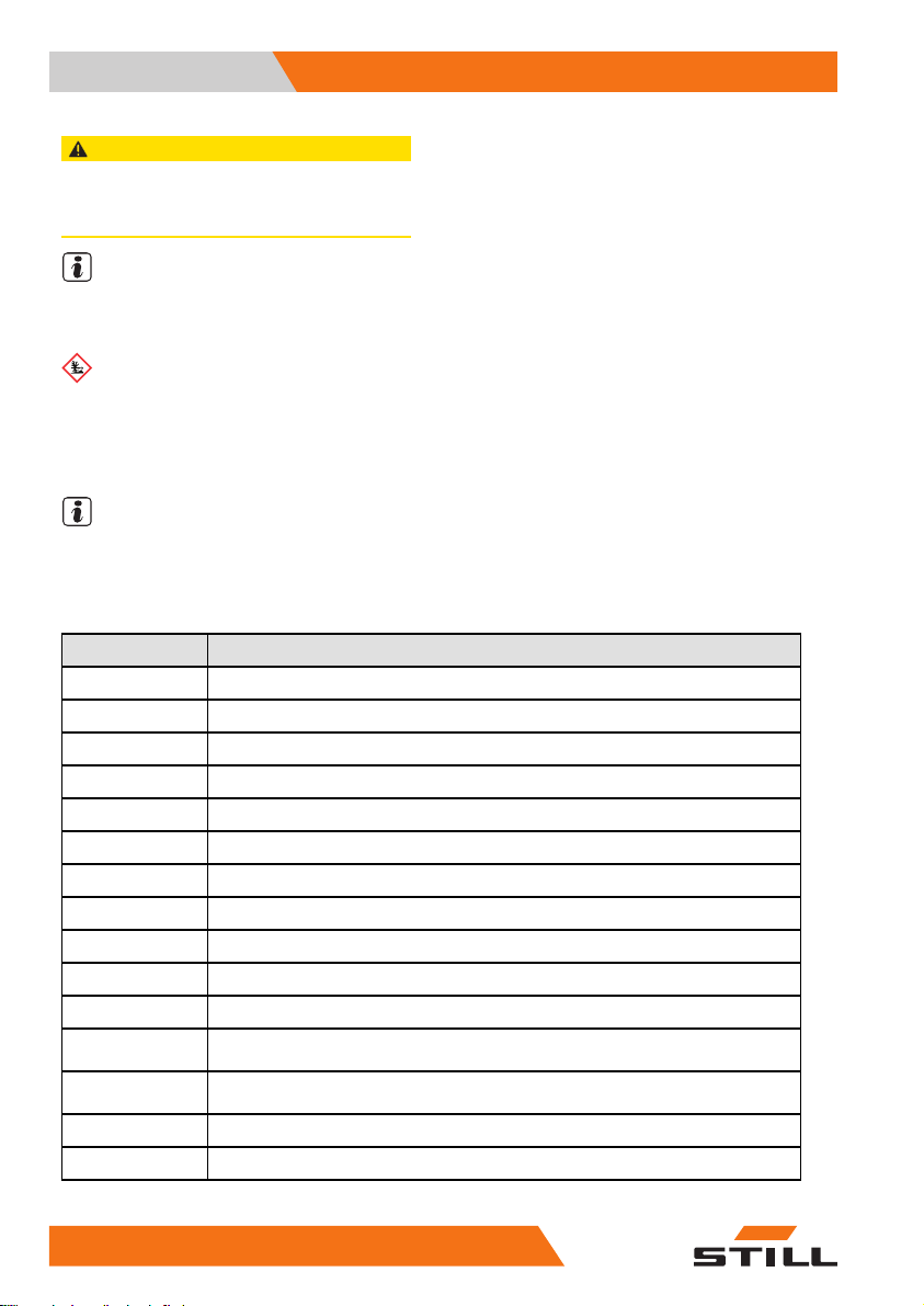
Defining directions
3
1
2
4
General:
• left (1)
•right(2)
Drive directions:
• Travelling in the load direction (backwards)
(3)
• Travelling in t
(4)
Movements of th
• Extending the reach carriage (in the load
direction) (5)
• Retracting the reach carriage (in the drive
direction) (6)
Tilting the lift mast or fork:
• Backward tilt
•Forwardtilt(8)
Thedriversitscrosswisetothedrivedirection.
he drive direction (forwards)
e reach carriage:
(7)
56
7
8
988078001 [EN] 9
50
Page 20
1 Foreword
Information about the documentati
Schematic views
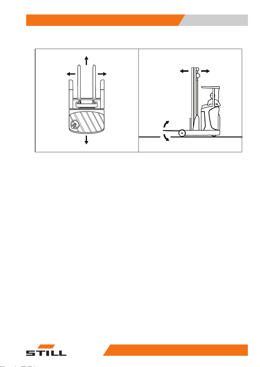
View of functions and operating procedures
At many points in this documentation, the
(mostly sequential) operation of certain functions or operating procedures is explained. To
illustrate these operations, schematic views of
a reach truck are used.
NOTE
These schematic views are not representative
of thestructural state of thedocumented truck.
The views are used solely for the purpose of
clarifying procedures.
View of the display and operating unit
NOTE
Views of operating statuses and values in the
display of the display and operating unit are
examples and partly dependent on the truck
equipment. As a result, the displays shown of
the actual operating statuses and values may
vary.
on
10
50988078001 [EN]
Page 21

Foreword 1
Environmental considerations
Environmental considerations
Packaging
During delivery of the truck, certain parts
are packaged to provide protection during
transport. This packaging must be removed
completely prior to initial start-up.
ENVIRONMENT NOTE
The packaging material mu
properly after delivery o
st be disposed of
f the truck.
Disposal of component
s and
batteries
The truckis composed
components or batter
and disposed of, they
• disposed of,
• treated or
• recycled in accorda
national regulatio
NOTE
The documentation provided by the battery
manufacturer must be observed when disposing of batteries.
ENVIRONMENT NOTE
We recommend working with a waste management company for disposal purposes.
of different materials. If
ies need to be replaced
must be:
nce with regional and
ns.
988078001 [EN] 11
50
Page 22

1 Foreword
Environmental considerations
12
50988078001 [EN]
Page 23

2
Introduction
Page 24
2 Introduction
Using the truck
Using the truck
Proper usage
The truck described in these operating instructions is suitable for lifting, transporting
and stacking loads.
The truck may only be used for its proper
purpose as set out and described in these
operating instructions.
If the truck is to be used for
than those specified in the o
tions, the approval of the m
applicable, the relevant r
must be obtained beforeha
ards.
The maximum load to be lifted is specified on
the capacity rating plate (load diagram) and
must not be exceeded; see also the chapter
entitled "Before picking up a load".
Impermissible use
The operating company or driver, and not the
manufacturer, is liable for any hazards caused
by improper use.
purposes other
perating instruc-
anufacturer and, if
egulatory authorities
nd to prevent haz-
NOTE
Please observe the
responsible perso
definition of the following
ns: "operating company"
and "driver".
Use for purposes other than those described
in these operating instructions is prohibited.
DANGER
There is a risk of fatal injury from
falling off the truck while it is moving!
– It is prohibited to carry passengers
on the truck.
The truck may not be operated in areas where
there is a risk of fire, explosion or corrosion, or
in areas that are particularly dusty.
Stacking or unstacking is not permissible on
inclined surfaces or ramps.
14
50988078001 [EN]
Page 25

Introduction 2
Using the truck
Place of use
The truck is only approved for indoor use.
The ground must have an adequate load
capacity (concrete, asphalt) and a rough
surface. Roadways, working areas and aisle
widths must conform to the specifications in
these operating instructions; see the chapter
entitled "Roadways".
Driving on upward and downwa
is permitted provided the de
specifications are observed
entitled "Roadways".
The truck is suitable for indoor use in many
different countries, ranging from those situated in the Tropics to those in Nordic regions
(temperature range: -10°C to +40°C).
If the truck is to be used in a cold store, it must
be configured accordingly and, if necessary,
approved for such an environment; see the
chapter entitled "Cold store application".
The operating company (
titled "Definition of te
rms used for responsible
persons") must provide
tion in the area surroun
dance with its applicat
application, addition
ding the truck in accor-
ion. Depending on the
al fire protection must be
provided on the truck. I
relevant authorities.
rd gradients
fined data and
; see the chapter
see the chapter en-
sufficient fire protec-
f in doubt, contact the
Parking in temperatu
res below -10°C
CAUTION
Batteries can freeze!
If the truck is parked in an ambient temperature
below -10°C for an extended period, the batteries
will cool down. The electrolyte may freeze and
damage the batteries. The truck is then not ready
for operation.
– When the ambient temperature is below -10°C,
only parkthe truck for short periodsof time.
988078001 [EN] 15
50
Page 26

2 Introduction
Using the truck
Using working platforms
WARNING
The use of working platforms is regulated by national law. The use of working platforms is only
permitted by virtue of the jurisdiction in the country
of use.
– Observe national legislation.
– Before using working platforms, consult the
national regulatory authorities.
16
50988078001 [EN]
Page 27

Introduction 2
Residual risk
Residual risk
Residual dangers, residual risks
Despite careful working and compliance with
standards and regulations, the occurrence
of other risks when using the truck cannot be
entirely excluded.
The truck and all other system components
comply with current safety requirements.
Nevertheless, even when the truck is used
for its proper purpose and all instructions
are followed, some residual risk cannot be
excluded.
Even beyond the narrow dan
truck itself, a residual r
Persons in this area aroun
exercise a heightened deg
so that they can react imme
of any malfunction, incid
WARNING
All persons that are in the vicinity of the truck
must be instructed regarding these risks that arise
through use of the truck.
In addition,we draw attention to the safety regulations in these operating instructions.
ger areas of the
isk cannot be excluded.
d the truck must
ree of awareness,
diately in the event
ent or breakdown etc.
The risks can include:
• Escape of consumables due to leakages,
rupture of lines and containers etc.
• Risk of accident when driving over difficult
ground such as gradients, smooth or
irregular surfaces, or with poor visibility
etc.
• Falling, tripping etc. when moving on
the truck, especially in wet weather, with
leaking consumables or on icy surfaces
• Fire and explosion risks due to batteriesand
electrical voltages
• Human error resulting from failure to
observe the safety regulations,
• Unrepaired damage or defective and worn
components,
• Insufficient maintenance and testing
• Use of incorrect consumables
• Exceeding test intervals
988078001 [EN] 17
50
Page 28

2 Introduction
Residual risk
The manufacturer is not held responsible for
accidents involving the truck caused by the
failure of the operating company to comply
with these regulations either intentionally or
carelessly.
Stability
The stability of the truck has been tested to
the latest technological standards and is
guaranteed if the truck is used properly and
according to its intended purpose. These
standards only take into account the static
and dynamic tipping forces that can arise
during specified use in accordance with the
operating rules and intended purpose. The
risk of exceeding the moment of tilt that arises
from improper use or incorrect operation
cannot be excluded in extreme cases, and
will impact stability.
The risks can include:
• loss of stability due to un
loads etc.
• cornering at excessive speeds,
• moving with the load raised,
• moving with a load that i
side (e.g. sideshift),
• turning and driving diagonally across
slopes,
• driving on slopes with the load on the
downhill side,
• loads that are too wide
• swinging loads,
• ramp edges or steps.
stable or sliding
s protruding to the
,
Special risks associated with using the truck and attachments
Approval from the manufacturer and attachment manufacturer must be obtained each
time the truck is used in a manner that falls
outside the scope of normal use, and in cases
where the driver is not certain that he can use
the truck correctly and without the risk of accidents.
18
50988078001 [EN]
Page 29

Introduction 2
Residual risk
988078001 [EN] 19
50
Page 30

2 Introduction
Residual risk
Overview of hazards and countermeasures
NOTE
This table is intended to help evaluate the
hazards in your facility and applies to all drive
types. It does not claim to be complete.
NOTE
Observe the national re
country!
Hazard Measure
Truck equipment does
not comply with local
regulations
Lack of skills and
qualification of driver
Usage by unauthorised persons
Truck not in a safe
condition
Risk of falling when
using working
platforms
Impaired visibility due
to load
Contamination of
respiratory air
gulations for your
Test
Driver training (sit-on
and stand-on)
Access with key only
for authorised persons
Recurrent testing and
rectification of defects
Compliance with
national regulations
(different national
laws)
Resource planning
Assessment of diesel
exhaust gases
Assessment of LPG
exhaust gases
Check note
√ actioned
- not applicable
O If in doubt, consult
O BGG 925
O
OBetrSichVO
OBetrSichVO
OBetrSichVO
O TRGS 554 and
OMAK(Maximum
Notes
competent factory
inspectorate or
employers’ liability
insurance association
VDI 3313 driver permit
(Workplace Safety
Ordinance)
(Workplace
Safety Ordinance)
and employer’s
liability insurance
associations
(Workplace Safety
Ordinance)
BetrSichVO
(Workplace Safety
Ordinance)
Workplace
Concentrations) list
and BetrSichVO
(Workplace Safety
Ordinance)
20
50988078001 [EN]
Page 31

Introduction 2
Residual risk
Hazard Measure
Impermissible usage
(improper usage)
When fuelling
a) Diesel Observe BetrSichVO
b) LPG Observe BGV D34,
When charging the
traction battery
When using battery
chargers
When parking LPG
trucks
Issuing of operating
instructions
Written notice of
instruction to driver
Observe BetrSichVO
(Workplace Safety
Ordinance), operating
instructions and
VDMA (German
Engineering
Federation) rules
(Workplace Safety
Ordinance), operating
instructions and
VDMA (German
Engineering
Federation) rules
operating instructions
and VDMA rules
Observe BetrSichVO
(Workplace Safety
Ordinance), operating
instructions and
VDMA (German
Engineering
Federation) rules
Observe BetrSichVO
(Workplace Safety
Ordinance), BGR
104 and operating
instructions
Observe BetrSichVO
(Workplace Safety
Ordinance), BGR
104 and operating
instructions
Check note
√ actioned
- not applicable
O BetrSichVO
O BetrSichVO
O
O
O
O
O BetrSichVO
O BetrSichVO
Notes
(Workplace Safety
Ordinance) and
ArbSchG (Health and
Safety at Work Act)
(Workplace Safety
Ordinance) and
ArbSchG (Health and
Safety at Work Act)
VDE 0510: In
particular
- Ensure ventilation
- Insulation value
within permissible
range
(Workplace Safety
Ordinance) and BGR
104
(Workplace Safety
Ordinance) and BGR
104
988078001 [EN] 21
50
Page 32

2 Introduction
Residual risk
Hazard Measure
With driverless transport systems
Roadway quality
inadequate
Load carrier
incorrect/slipped
Drive behaviour
unpredictable
Driveways blocked Mark driveways
Driveways intersect
No person detection
during depositing and
retrieval
.
Danger t
Accordi
ordinan
law (Arb
determi
ation, a
and safe
ees (Bet
must the
instruc
availab
must be a
o employees
ng to the German workplace safety
ce (BetrSichVO) and labour protection
SchG), the operating company must
ne and assess hazards during oper-
nd establish the occupational health
ty measures required for employrSichVO). The operating company
refore draw up appropriate operating
tions (§ 6 ArbSchG) and make them
le to the driver. A responsible person
ppointed.
Clean/clear driveways O BetrSichVO
Reattach load to pallet
Employee training
Keep driveways clear
Announce right-ofway rule
Employee training
Check note
√ actioned
- not applicable
OBetrSichVO
OBetrSichVO
OBetrSichVO
OBetrSichVO
OBetrSichVO
Notes
(Workplace Safety
Ordinance)
(Workplace Safety
Ordinance)
(Workplace Safety
Ordinance)
(Workplace Safety
Ordinance)
(Workplace Safety
Ordinance)
(Workplace Safety
Ordinance)
NOTE
Please observe the definition of the following
responsible persons: "operating company"
and "driver".
The construction and equipment of the
truck correspond to the Machinery Directive
2006/42/EC and are therefore marked with
CE labelling. These elements are therefore
not included in the hazard assessment. At-
22
50988078001 [EN]
Page 33

Introduction 2
Residual risk
tachments possess their own CE labelling and
likewise are not included for that reason. The
operating company must, however, select the
type and equipment of thetrucks so as to comply with the local provisions for deployment.
The result must be documented (§ 6 ArbSchG). In the case of truck applications involving similar hazard situations, the results may
be summarised. This overview (see chapter
"Overview of hazards and countermeasures")
provides help on complying with this regulation. The overview specifies the main hazards
that are the most frequent cause of accidents
in the event of non-compliance. If other major
operational hazards are involved, they must
also be taken into consideration.
The conditions of use for tr
similar in many plants, so t
be summarised in one overvi
the information provided b
employers’ liability insu
this subject.
ucks are broadly
he hazards can
ew. Observe
y the relevant
rance association on
988078001 [EN] 23
50
Page 34

2 Introduction
Residual risk
24
50988078001 [EN]
Page 35

3
Safety
Page 36

3 Safety
Definition of terms used for respons
ible persons
Definition of terms used for responsible persons
Operating company
The operating company is the natural or legal
person or group who operates the truck or on
whose authority the truck is used.
The operating company must ensure that the
truck is only used for its proper purpose and in
compliance with the safety regulations set out
in these operating instructions.
The operating company must
all users read and understa
information.
The operating company is responsible for the
scheduling andcorrect performance of regular
safety checks.
We recommend that the national performance
specifications are adhered to.
Specialist
A qualified person is defined as a service
engineer or a person who fulfils the following
requirements:
• A completed vocation
demonstrably proves
expertise. This proo
a vocational qualifi
document.
• Professional experience indicating that
the qualified person has gained practical
experience of industrial trucks over a
proven period during their career During
this time, this person has become familiar
with a wide range of symptoms that require
checks to be carried out, such as based
on the results of a hazard assessment or a
daily inspection
• Recent professional involvement in the
field of the industrial truck test in question
and an appropriate further qualification
are essential. The qualified person must
have experience of carrying out the test
in question or of carrying out similar tests.
Moreover, this person must be aware of
the latest technological developments
cation or a similar
ensure that
nd the safety
al qualification that
their professional
f should consist of
26
50988078001 [EN]
Page 37

Safety 3
Definition of terms used for respons
regarding the industrial truck to be tested
and the risk being assessed
ible persons
Drivers
This truck may only be driven by suitable persons who are at least 18 years of age, have
been trained in driving, have demonstrated
their skills in driving and handling loads to
the operating company or an authorised representative, and have been specifically instructed to drive the truck. Specific knowledge
of the truck to be operated is also required.
The training requirements under §3 of the
Health and Safety at Work Act and §9 of the
plant safety regulations are deemed to have
been satisfied if the driver has been trained in
accordance with BGG (General Employers’
Liability Insurance Association Act) 925.
Observe the national regulations for your
country.
Driver rights, duties and rules of behaviour
The driver must be trai
duties.
The drivermust be grantedthe required rights.
The driver must wear protective equipment
(protection suit, safety footwear, safety
helmet, industrial goggles and gloves) that
is appropriate for the conditions, the job and
the load to be lifted. Solid footwear should be
worn to ensure safe driving and braking.
Thedrivermustbefa
instructions and ha
times.
The driver must:
• have read and understood the operating
manual
• have familiarised himself with safe operation of the truck
• be physically and m
truck safely
ned in his rights and
miliar with the operating
ve access to them at all
entally able to drive the
988078001 [EN] 27
50
Page 38

3 Safety
Definition of terms used for respons
DANGER
The use of drugs, alcohol or medicationsthat affect
reactions impair the ability to drive the truck!
Individuals under the influence of the aforementioned substancesare not permitted to perform work
of any kind on or with the truck.
Prohibition of use by unauthorised
persons
The driver is responsible for the truck during
working hours. He must not allow unauthorised persons to operate the truck.
When leavingthe truck, thedriver must secure
it against unauthorised use, e.g. by pulling out
the key.
ible persons
28
50988078001 [EN]
Page 39

Safety 3
Basic principles for safe operatio
Basic principles for safe operation
Insurance cover on company premises
In many cases, company premises are
restricted public traffic areas.
NOTE
The business liability insurance should be
reviewed to ensure that, in the event of any
damage caused in restricted public traffic
areas, there is insurance cover for the truck in
respect of third parties.
Changes and retrofitting
If the truck is used for work that is not listed
in the guidelines or in these instructions and
has to be converted or retrofitted accordingly,
you must note that any change to its structural
state can affect the handling and stability of
the truck, which in turn can lead to accidents.
You should therefor
centre beforehand.
Changes that will adversely affect stability,
load capacity, safety systems etc. must not be
made without the manufacturer’s approval.
Thetruckmayonlybeconvertedwithwritten
approval from the manufacturer. Approval
from the relevant authority must be obtained
where applicable.
In addition, chan
control elements
ment variants (e.
made without the p
manufacturer.
DANGER
There isa risk of accident due to restrictedvisibility.
Additional attachments (e.g. terminals, printers,
mirrors) in the driver’s compartment area can
restrict the driver’s field of vision.
– Only install attachments (variants) that have
been specifically approved by STILL in accordance with the safety regulations.
e contact your service
ges to the brakes, steering,
, circumferential view, equipg. attachments) must not be
rior written approval of the
n
988078001 [EN] 29
50
Page 40

3 Safety
Basic principles for safe operatio
Only restraint systems (variants) that have
been specifically approved by STILL may be
installed and used.
DANGER
Risk ofinjury if truck tips over!
Even if the driver has fastened the
seat belt (variant), there is still a
residual risk of injury if the truck
tips over. In addition, the seat belt
protects against the consequences
of rear-endcollisions and falling off a
ramp.
– The seatbelt (variant)must always
be used.
When carrying out welding work on the
truck, it is essential that the battery and all
connections to the electronic control cards are
disconnected. Contact the authorised service
centre on this matter.
In the event of the manufacturer going into
liquidation and the company not being taken
over by another legal person, the operating
company can make changes to the truck.
To do so, the operating company must fulfil
the following prerequisites:
Design documents, test documents and
assembly instructions associated with the
change must be archived and remain accessible at all times.
The capacity rating plate, decal information,
hazard warnings and the operating instructions must be checked to ensure they are
consistent with the changes and modified if
required.
The modification must be designed, checked
and implemented by a design office that
specialises in industrial trucks in accordance
with the standards and directives valid at the
time the modification is made.
Decal information with the following data must
be permanently affixed to the truck so that it is
clearly visible:
– Type of modification
– Date of modification
n
30
50988078001 [EN]
Page 41

Safety 3
Basic principles for safe operatio
– Name and address of the company imple-
menting the modification.
Modifications to the overhead guard
and cabs
DANGER
The overhead guard or the weather protection
cab/cold store cab may fail. A falling load or the
truck tipping over couldresult in fatalconsequences
for the driver. There is a risk of fatal injury!
Work on the overhead guard or on the weather
protection cab/cold store cab reduces its stability.
Excessive forces caused by falling loads or the
truck tipping over may result in buckling of the
modified chassis, bodywork and fittings. This could
mean thatthe driver is no longerprotected.
– Do not weld on the overhead guard or the
weather protection cab/cold store cab.
– Do not drill on the overheadguard orthe weather
protection cab/cold store cab.
– Do not make any incisions on the overhead
guard or the weather protection cab/cold store
cab.
DANGER
Risk of explosion from additional
bores on the truck chassis, weather
protection cab or cold store cab!
Explosive gases can escape and
lead to potentially fatalinjuries if they
explode. Sealing bores with plugs
is not sufficient to prevent gas from
escaping.
– Do not drill any additional holes
in the truck chassis, weather
protection cab or cold store cab.
n
Roof loads
To ensure the stability of the chassis, bodywork and fittings at all times, do not mount any
additional roof loads on the truck.
988078001 [EN] 31
50
Page 42

3 Safety
Basic principles for safe operatio
CAUTION
Additional roof loads damage the overhead guard
or the weather protection cab/cold store cab.
– Do not mount any additional roof loads on the
truck.
Safety information for FM-X Wide, ExtraWide(W,EW)
The W (Wide) and EW (Extra Wide) versions
differ from the standard truck by having
additional cover sheets (1) between the
overhead guard and the widened chassis.
These sheets are located on each side of the
truck. They are not designed to be walked on
by people.
WARNING
Risk of accident if a person steps on to the lateral
cover sheets
If a person steps on to the cover plates, the plates
can be damaged by the weight of the person, who
may also slip and suffer injury.
– Do not step on the lateral cover sheets
n
1
Warning regardingnon-original parts
Original parts, attachments and accessories
are specially designed for this truck. We
specifically draw your attention to the fact that
parts, attachments and accessories supplied
by other companies have not been tested and
approved by STILL.
CAUTION
Installation and/or use ofsuch products may therefore have a negative impact on the design features
of the truck and thus impair active and/or passive
driving safety.
We recommend that you obtain approval from the
manufacturer and, if necessary, from the relevant
regulatory authorities before installing such parts.
The manufacturer accepts no liability for any damage caused by the use of non-original parts and
accessories without approval.
32
50988078001 [EN]
Page 43

Safety 3
Basic principles for safe operatio
Damage, defects and misuse of safety systems
Damage or other defects on the truck or
attachment must be reported to the supervisor
or responsible fleet manager immediately so
that they can have the defect rectified.
Trucks andattachments that are not functional
or safe to drivemay not be used until they have
been properly repaired.
Do not remove or deactivate
and switches.
Fixed set valuesmay only be changed withthe
approval of the manufacturer.
Work onthe electrical system (e.g. connecting
a radio, additional headlights etc.) is only
permitted with the manufacturer’s written
approval. All electrical system interventions
must be documented.
Even if they are removabl
not be removed, as they a
protect against small f
safety systems
e, roof panels may
re designed to
alling objects.
Tyres
n
DANGER
Using different tyres has a negative effect on the
stability of the truck. There is a risk of accident!
Only originaltyres may be fitted to the truck.
– Make sure that only original tyres are fitted.
Tyre quality affects the stability and handling
of the truck. Changes must only be made in
consultation with the manufacturer. When
changing wheels or tyres, always ensure that
this does not cause the truck to tilt to one side
(e.g. always replace right and left wheels at
the same time).
988078001 [EN] 33
50
Page 44

3 Safety
Basic principles for safe operatio
Medical equipment
WARNING
Electromagneticinterference may occuron medical
devices!
Only use equipment that is sufficiently protected
against electromagnetic interference.
Medical equipment, such as pacemakers or
hearing aids, may not work properly when the
truck is in operation.
– Ask your doctor or the manufacturer of
the medical equipment to confirm that the
medical equipment is sufficiently protected
against electromagnetic interference.
Exercise caution when handling gas springs and accumulators
WARNING
Gas springs are under high pressure. Improper
removal resultsin an elevated risk of injury.
For ease of operation, various functions on the
truck can be supported by gas springs. Gas springs
are complex components that are subject to high
internal pressures (up to 300 bar). They may under
no circumstances be opened unless instructed to
do so, and may be installed only when not under
pressure. If required, the authorised service centre
will depressurisethe gas spring in accordancewith
the regulationsbefore removal. Gas springs must
be depressurised before recycling.
– Avoid damage, lateralforces, buckling, tempe-
ratures over 80°C and heavy contamination.
– Damaged or defective gas springs must be
changed immediately.
– Contact the authorisedservice centre.
n
WARNING
Accumulators are under high pressure. Improper
installation of an accumulatorresults in an elevated
risk of injury.
Before startingwork on the accumulator it must be
depressurised.
– Contact the authorisedservice centre.
34
50988078001 [EN]
Page 45

Safety 3
Safety tests
Safety tests
Regular safety inspection of the truck
Safetyinspectionbasedontimeand
extraordinary incidents
The operating company must ensure that the
truck is checked by a specialist at least once a
year or after particular incidents.
As part of this inspection
of the technical conditio
performed with regard to a
In addition, the truck mus
checked for damage that co
have been caused by impro
log must be created. The r
inspection must be retai
inspections have been ca
The inspection date is indicated by an adhesive label on the truck.
– Arrange for the service centre to perform
periodic safety inspections on the truck.
– Observe guidelines fo
on the truck in accorda
The operator is responsible for ensuring any
defects are remedied without delay.
– Contact your service centre.
, a complete check
n of the truck must be
ccident safety.
t be thoroughly
uld potentially
per use. A test
esults from the
ned until a further two
rried out.
r checks carried out
nce with FEM 4.004.
NOTE
Observe the national regulations for your
country!
Insulation testing
The truck insulation must have sufficient insulation resistance. For this reason, insulation
testing in accordance with DIN EN 1175 and
DIN 43539, VDE 0117 and VDE 0510 must be
conducted at least once a year.
NOTE
The truck’s el
ries must be ch
ectrical system and drive batte-
ecked separately.
988078001 [EN] 35
50
Page 46

3 Safety
Safety regulations for handling co
Measuring the battery’s insulation
resistance
NOTE
Nominal battery voltage < test voltage < 500
V.
– Measure the insulation resistance with a
suitable measuring device.
The insulation resistance can be considered
sufficient if it measures at least 500
nominal battery voltage against ground.
– Contact the authorised service centre.
Measuring the insulation resistance of
the electrical system
NOTE
Nominal battery voltage < test voltage < 500
V.
– Ensure that all volt
disconnected from t
– Measure the insulation resistance with a
suitable measuring device.
The insulation resistance can be considered
sufficient if it measures at least 1000
the nominal battery voltage against ground.
– Contact the author
age sources have been
he circuit to be tested.
ised service centre.
nsumables
/V for the
/V for
Safety regulati
Permissible co
DANGER
Failure to observethe safety regulations relating to
consumables may result in a risk of injury, death or
damage to the environment.
– Observe the safety regulations when handling
these materials.
Refer to the maintenance data table for information regarding the permissible substances
that are necessary for operation (refer to the
chapter entitled "Maintenance data table").
36
ons for handling consumables
nsumables
50988078001 [EN]
Page 47

Safety 3
Safety regulations for handling co
nsumables
Oils
DANGER
Oils are flammable!
– Follow the statutory regulations.
– Donotallowoilstocomeinto
contact with hot engine parts.
– No smoking,fires ornaked flames!
DANGER
Oils are toxic!
– Avoid contact and consumption.
– If vapour or fumes are inhaled,
move to fresh air immediately.
– In the event of contact with the
eyes, rinsethoroughly (for at least
10 minutes) with water and then
consult an eye specialist.
– If swallowed, do not induce
vomiting. Seek immediate medical
attention.
WARNING
Prolonged intensive contact with the
skin can result in dryness and irritate
the skin!
– Avoid contact and consumption.
– Wear protective gloves.
– After any contact, wash the skin
with soap and water, and then
apply a skin care product.
– Immediately change soaked
clothing and shoes.
WARNING
There is a risk of slipping on spilled oil, particularly
when combined with water!
– Spilt oil should be removed immediately with
oil-binding agents and disposed of according to
the regulations.
988078001 [EN] 37
50
Page 48

3 Safety
Safety regulations for handling co
ENVIRONMENT NOTE
Oil is a water-polluting subst
•
Always store oil in containers
ance!
with the applicable regulatio
•
Avoid spilling oils.
•
Spilt oil should be removed immediately
with oil-binding agents and disposed of
according to the regulations.
•
Dispose of old oils accordin
tions.
Hydraulic fluid
WARNING
These fluids are pressurised during
operation of the truck and are
hazardous to your health.
– Do not spill the fluids.
– Follow the statutory regulations.
– Do not allow the fluids to come into
contact withhot engine parts.
nsumables
that comply
ns.
gtotheregula-
WARNING
These fluids are pressurised during
operation of the truck and are
hazardous to your health.
– Do not allow the fluids to come into
contact with the skin.
– Avoid inhaling spray.
– Penetration of pressurised
fluids into the skin is particularly
dangerous if these fluids escape
at high pressure due to leaks in
the hydraulic system. In case of
such injury, immediate medical
assistance is required.
– To avoid injury, use appropriate
personal protective equipment
(e.g. protective gloves, industrial
goggles, skin protection and skin
care products).
38
50988078001 [EN]
Page 49

Safety 3
nsumables
ENVIRONMENT NOTE
Hydraulic fluid is a water-poll
•
Always store hydraulic fluid in
Safety regulations for handling co
uting substance.
containers
that comply with regulations
•
Avoid spills
•
Spilt hydraulic fluid should be removed
immediately with oil-binding agents and
disposed of according to the regulations
•
Dispose of old hydraulic flui
d according to
the regulations
Battery acid
WARNING
Battery acid contains dissolved
sulphuric acid. This is toxic.
– Avoid touching or swallowing the
battery acid at all costs.
– In case of injury, seek medical
advice immediately.
WARNING
Battery acid contains dissolved
sulphuric acid. This is corrosive.
– When working with battery acid,
always wear a protection suit and
eye protection.
– When working with battery
acid, never wear a watch or any
jewellery.
– Do not allow any acid to get
onto clothing or skin or into the
eyes; if this does happen, rinse
immediately with plenty of clean
water.
– In case of injury, seek medical
advice immediately.
– Immediately rinse away spilt
battery acid with plenty of water.
– Follow the statutory regulations.
ENVIRONMENT NOTE
– Dispose of used battery acid in line with the
applicable regulations.
988078001 [EN] 39
50
Page 50

3 Safety
Safety regulations for handling co
Brake fluid
WARNING
Brake fluid is poisonous!
– Avoid swallowing. In the event
of swallowing, do not induce
vomiting. Rinse out your mouth
thoroughly with water and ask a
doctor for advice.
– Avoid aerosolisation and inha-
lation. In the event of inhalation,
seek freshair. Ask a doctor for ad-
vice if necessary.
WARNING
Brake fluid is hazardous to your
health!
Brake fluid irritates the eyes and
can dry out the skin upon prolonged
contact.
– Coat your hands with a protective
skin cream prior to starting work.
– Avoid prolonged or intensive
skin contact. In the event of skin
contact, clean the wetted skin with
water and soap, and subsequently
apply a skin care product.
– Prevent contact with the eyes. In
the event of contact with the eyes,
wash out the affected eye(s) with
clean water for ten minutes and
then ask a doctor for advice.
– Change clothing soiled with brake
fluid as soon as possible.
nsumables
CAUTION
Brake fluid is flammable!
– Do not allow brake fluid to come into contact with
hot motor parts.
– Smoking, fires and naked flames are prohibited.
CAUTION
Brake fluid has strong dissolvingand colour-changing properties.
– Immediately rinse off any brake fluid that has
splashed on paint, clothing, and shoes with
plenty of water
40
50988078001 [EN]
Page 51

Safety 3
Emissions
ENVIRONMENT NOTE
Brake fluid is a water pollutant
•
Always store brake fluid in cont
complying with the regulation
•
Do not spill brake fluid.
•
Spilt brake fluid must be removed immedia-
!
ainers
s..
tely using an oil binding agent and disposed
of in accordance with regulations
•
Dispose of old brake fluid acc
ording to the
regulations.
•
Observe the national regulations for the
country in which the truck is being used.
Disposal of consumables
ENVIRONMENT NOTE
Materials that accumulate during repair,
maintenance and cleaning must be collected
properly and disposed of in accordance with
the national regulations for the country in
which the truck is being used. Work must
only be carried out in areas designated for the
purpose. Care must be taken to minimise any
environmental pollution.
– Soak up any spilt fluids such as hydraulic
oil, brake fluid or gearbox oil using an
oil-binding agent.
– Neutralise any spil
ately.
– Always observe national regulations con-
cerning the disposal of used oil.
t battery acid immedi-
Emissions
The values specified apply to a standard truck
(see technical datasheet). Different tyres,
lift masts, additional units etc. may produce
different values.
Noise emissions
The values were determined using the measuring procedures from the EN 12053 stan-
988078001 [EN] 41
50
Page 52

3 Safety
Emissions
dard (noise measurement for industrial trucks
based on EN 12001 and EN ISO 3744 and the
requirements of EN ISO 4871).
This machine emits the following sound
pressure level:
Continuous sound pressure lev
driver’s compartment
el in the
L
pAZ
< 69.5 dB(A)
The values were determined in the test cycle
on an identical machine from the weighted
values for operating statuses and idling.
Time proportions:
• Lifting 18%
• Idling 58%
• Driving 24%
However, the specified noi
truck cannot be used to det
emissions occurring in wo
dance with the most rece
2003/10/EC (daily pers
necessary, these value
directly at the workpla
tions present there (ad
special application co
se levels in the
ermine the noise
rkplaces in accor-
nt version of Directive
onal noise pollution). If
s must be determined
ce in the actual condi-
ditional noise sources,
nditions, sound reflec-
tions).
Vibrations
The vibrations of the machine have been
determined on an identical machine in accordance with the standards DIN EN 13059
"Safety of industrial trucks - Test methods
for measuring vibration" and DIN EN 12096
"Mechanical vibration - Declaration and verification of vibration emission values".
Weighted effective value of accelerationto which the body
(feet or seat surface) is subjected.
Uncertainty K
0.39 m/s
0.117 m/s
2
2
Tests have indicat
hand and arm vibrat
or the operating d
2
2.5 m/s
. There ar
ment guidelines f
42
or these measurements.
ed that the amplitude of the
ions on the steering wheel
evices in trucks is less than
e therefore no measure-
50988078001 [EN]
Page 53

Safety 3
Emissions
The personal vibration load on the driver
over a working day must be determined in
accordance with Directive 2002/44/EC by the
operating company at the actual place of use,
in order to consider all additional influences,
such as driving route, intensity of use etc.
Battery
DANGER
Risk of explosion due to flammable
gases!
During charging, the batteryreleases
a mixture of oxygen and hydrogen
(oxyhydrogen gas). This gas mixture
is explosive and must not be ignited.
– Make sure that there is always
sufficient ventilation in working
areas that are entirely or partially
enclosed.
– Keep away from open flames and
flying sparks.
– Observe the safety regulations for
handling the battery.
988078001 [EN] 43
50
Page 54

3 Safety
Emissions
44
50988078001 [EN]
Page 55

4
Overviews
Page 56

4 Overviews
Overview
Overview
321
4
11
1 Overhead guard
2 Driver’s compartment
3Liftmast
4 Fork arms
5 Load wheel
6Batteryframe
46
910
8
7Battery
8 Side support (tilt protection)
9 Control compartment
10 Drive wheel
11 Step
50988078001 [EN]
7
5
6
Page 57

Overviews 4
Overview of the driver’s compartme
Overview of the driver’s compartment
nt
123
1 Steering wheel
2 Working spotlightpush button (variant)
3 Key switch or push button (variant)
4 Reserved
5 Electrical seat adjustment push button
(variant)
6 Compartment (reserved for add-on sys-
tems)
7 Display and operating unit
8 Cup holderfor max. 1.5-l bottles
4
5
67
8
9
10
11
12131415
9 Operating devices for hydraulic and traction
functions
10 Emergency off switch
11 Push button for additional hydraulic func-
tions
12 Accelerator pedal
13 Brake pedal
14 Foot switch
15 Driver’s seat
988078001 [EN] 47
50
Page 58

4 Overviews
Operating devices and display elem
ents
Operating devices and display elements
Display and operating unit
1 Display of t
2 Keypad for l
or PIN code
3Keypadfo
terisin
4Drivep
5 Blue-Q
6Parki
rating devices for hydraulic and
Ope
ction functions
tra
ferent versions of the operating devices are
Dif
ilable for operating the truck’s hydraulic
ava
traction functions. The truck can be
and
ipped with the following operating devices:
equ
• Joystick 4Plus
• Fingertip
48
he operatingstatuses
ift height preselection (variant)
access (variant)
r onboard diagnostics, parame-
g
rogramme button (P1-P4)
button
ng brake button
50988078001 [EN]
Page 59

Overviews 4
Operating devices and display elem
ents
Joystick 4Plus
6
7
2
3
4
5
18
5
4
9
10
15
11
121314
1 "Transition shift"slider
2 Shift button "F" (auxiliary hydraulics con-
troller)
3 Drive direction switch
4 Joystick, "lifting/lowering" function
5 Joystick, "shifting" function
6 "Tilt" rocker button
7 Signal horn button
8 "Enable" push button (variant)
9 "Load measurement" push button (variant)
10 "Transition shift/tilt centre position" push
button (variant)
11 Reserve
12 Pictograms for operation of the 5th and 6th
hydraulic function (variant)
13 Pictograms for operation of the basic hy-
draulic functions
14 Pictograms for operation of the 3rd and 4th
hydraulic function
15 LED indicator light for clamp locking mecha-
nism (variant)
988078001 [EN] 49
50
Page 60

4 Overviews
Operating devices and display elem
Fingertip
12 3
ents
4
5
6
7
8
9
12
11
10
1 "Lift/lower" operating lever
2 "Shift" operatinglever
3 "Tilt" operating lever
4 "Transition shift" operating lever
5 Emergency off switch
6 "Enable" push button (variant)
7 "Load measurement" push button (variant)
50
8 "Transition shift/tilt centre position" push
button (variant)
9Reserve
10 "Auxiliary hydraulics"push button (variant)
11 Drive direction switch
12 Signal horn button
50988078001 [EN]
Page 61

Overviews 4
Identification points
Identification points
Overview
1
4
2
5
5
1
14
3
13
2
15
12
11
10
2
3
4
5
6
9
5
8
7
10
9
6
7
8
11
12
13
988078001 [EN] 51
50
14
X<= 15mm
15
mm
mm
mm
800
700
400-600
kgkg
kg
750
860
970
1050
1080
1160
1200
1270
X
mm
850
1000
10200
1150
9800
980
1300
9500
1110
1400
9300
1200
1450
9000
1240
1500
8750
1320
1600
8300
1600
1700
7100
1700
Page 62

4 Overviews
Identification points
1 Warning sign: Do not stand underneath the
fork/Do not stand on the fork/Danger due to
shearing/Danger due to high fluid pressure
2 Decal information: Caution/read the operat-
ing instructions
3 Warning sign: Danger due to shearing
4 Decal information: Battery version
5 Decal information: Hydraulic oil tank
6 Decal information: Lifting point
7 Warning sign: Crushing andshearing points
for feet
8 Decal information: Cold store version
(variant)
Nameplate
The truck can be identified from the information on the nameplate.
9 Decal information: Electrical seat adjust-
ment (variant)
10 Decal information: FEM test
11 Decal information: FEM test (inspection
sticker)
12 Decal information: Nameplate
13 Warning sign: Passengers prohibited
14 Warning sign: Reverse steering
15 Decal information: Load capacity diagram,
load capacity diagram for attachments
(example)
1
Type-Modèle-Typ / Serial no.-No. de série-Serien-Nr. / year-année-Baujahr
12
Rated capacity
Capacité nominale
Nenn-Tragfähigkeit
11
Battery voltage
Tension batterie
Batteriespannung
10
Rated drive power
Puissance motr.nom.
Nenn-Antriebsleist.
2
Unladen mass
kg
Masse à vide
Leergewicht
V
kW
* see Operating instructions
voir Mode d'emploi
siehe Betriebsanleitung
9
max
min.*
*
8
kg
kg
kg
kg
6210_921-003_V2
3
4
5
6
7
1 Type
2 Production number
3 Year of manufacture
4 Tare weight in kg
5 Max. permissible battery weight in kg (for
electric forklift trucks only)
6 Min. permissible battery weight in kg (for
electric forklift trucks only)
7 Ballast weight in kg (forelectric forklifttrucks
only)
8 Refer to the technical data listed in these
operating instructions for more detailed
information
9 CE labelling
10 Nominal drive power in kW
11 Battery voltage in V
12 Rated capacity in kg
52
50988078001 [EN]
Page 63

Overviews 4
Identification points
Production number
NOTE
The production number is used to identify the
truck. It can be found on the nameplate and
must be referred to in all technical questions.
The production number con
coded information:
(1) Production location
(2) Model
(3) Year of manufacture
(4) Sequential number
tains the following
xx xxxx x xxxxx
1
2
3
4
7090_921-004
988078001 [EN] 53
50
Page 64

4 Overviews
Identification points
54
50988078001 [EN]
Page 65

5
Operation
Page 66

5 Operation
Checks and tasks to be carried out pr
ior to commissioning
Checks and tasks to be carried out prior to commissioning
Visual inspections
WARNING
Risk of accident due to damage orother defects on
the truck or on the attachment (variant)!
Damage to the truck or the attachment(variant) can
lead to unpredictable and dangerous situations.
If damage or other defects are identified on the
truck or attachment (variant) during the following
inspections, the truck must not be used until it has
been properly repaired.
– Do not remove or deactivate safety systems or
switches.
– Do not change any predefined set values.
– Do not use the truck until it has been properly
repaired.
WARNING
There is a risk of falling when working on high parts
of the truck.
– Use only the steps provided on the truck.
– Do not stand on truck componentsor use them
to help you climb onto the truck.
– Use suitable equipment.
Prior to commissioning, ensure that the truck
is safe for operation:
• All covers must be fitted and closed
• The fork arms must be secured against
lifting and shifting
• The locking devices (1) of the fork arms
must not be damaged or deformed
• Fork arms and other lifting accessories
must not show any noticeable damage (e.g.
bends, cracks, significant wear)
• The roller tracks (2) must be lubricated with
a visible grease film
• The slide tracks of the reach carriage must
be lubricated with a visible film of grease
• The chains must not be damaged and must
be evenly and adequately tensioned
• Check the area under the truck for leaking
consumables
• The guard grille (variant) and overhead
guard or weather protection cab/cold store
56
2
1
50988078001 [EN]
Page 67

Operation 5
Checks and tasks to be carried out pr
cab (variant) must be undamaged and
securely mounted
• Attachments (variant) must be properly
attached and function according to their
operating instructions
• All decal information signs mu
place and legible. Replace d
missing adhesive labels in a
the overview in the "Identifi
chapter
• Any warning units (e.g. signal horn) must be
in perfect condition and function correctly
• Check the visible areas of the hydraulic system for damage and leakages. Damaged
hoses must be replaced
• The battery frame must be fu
towards the drive side and m
securely in this position
• Check the battery male connector for
damage (e.g. cracks, breaksor deformation
of the housing, and whether the contacts
are bent or damaged). If necessary, have
the battery male connector replaced by the
authorised service centre
• With an internal roller channel (variant), the
swing boltof the batterylock must be closed
and must not be damaged or deformed
• The battery frame must sh
damage (e.g. cracks or br
• Steps must be clean and free of ice
• Any panes of glass (even for the weather
protection cab/cold store cab variant) must
be clean and free of ice
• Depending on the tyres,
with an earthing strap.
must not be damaged. It m
and long enough to touch
• Damage or other defects on the truck or
attachment (variant) must be reported to
the supervisor or responsible fleet manager
immediately sothat they can arrange for the
defect to be rectified.
st be in
amaged or
ccordance with
cation points"
lly retracted
ust be locked
ow no noticeable
eaks)
the truck is fitted
The earthing strap
ustalsobeclean
the ground
ior to commissioning
988078001 [EN] 57
50
Page 68

5 Operation
Checks and tasks to be carried out pr
WARNING
Risk of component damage!
A deformed or damaged battery male connector
can cause overheating and related consequential
damage.
– Check the battery male connector for damage.
– If necessary, have the battery male connector
replaced by the authorised service centre.
Filling the washer system (variant)
The washer reservoir is located behind the
driver’s seat in the weather protection cab.
The filling opening is accessible from above.
– Open the washer system filler cap (1).
– Fill the washer reservoir with washer
fluid and anti-freeze according to the
maintenance data table (see the chapter
entitled "Maintenance data table").
CAUTION
Components may become damaged due to the
effects of frost!
Water expands when it freezes. If there is no antifreeze in the washer system (variant), the system
may become damaged due to the accumulation of
ice in freezing conditions.
– Always use washer fluid containinganti-freeze.
ior to commissioning
1
– Observe the maximum fill level of the
reservoir (approx. 10 mm below the filler
neck).
– Close the filler cap.
– Operate the washer system until washer
fluid is discharged from the spray nozzles.
58
50988078001 [EN]
Page 69

Operation 5
Checks and tasks to be carried out pr
ior to commissioning
Checking the condition of the wheels and tyres
WARNING
Risk of accident! Uneven wearreduces the stability
of thetruck and increases the braking distance.
– If the tyres are worn or damaged, inform the
authorised service centre immediately
NOTE
Only approved tyre types may be used;
•
see the chapter entitled Technical data,
"Wheels and tyres".
– Check the tyres (1) on the drive wheel and
load wheels for wear and damage.
Tyres must not be damaged or excessively
worn. They must be worn evenly on both
sides.
NOTE
Observe the safety principles for tyres; refer to
the chapter entitled "Basic principles for safe
operation/Tyres".
1
1
988078001 [EN] 59
50
Page 70

5 Operation
Checks and tasks to be carried out pr
Adjusting the MSG 65/MSG 75
driver’s seat
DANGER
There is arisk of accidentif the seator seat backrest
shifts suddenly, which could cause the driver to
move in an uncontrolled manner. This can result
in unintentional actuation of the steering or the
operating devices and thus cause uncontrolled
movements of the truck or load.
– Do not adjust the seat or seat backrest while
driving.
– Adjust the seat and seat backrest so that all
operating devices can be actuated safely.
– Ensure that the seat and seat backrest are
securely engaged.
WARNING
To obtain optimum seat cushioning, you must adjust the seat suspension to your own body weight.
This is betterfor yourback and protectsyour health.
– To prevent injury, make sure that there are no
objects withinthe seat’s swivel area.
Moving the driver’s seat
– Lift the lever (1) and hold.
– Push the driver’s seat into the desired
position.
– Release the lever.
– Ensure that the driver’s seat is securely
engaged.
ior to commissioning
1
60
50988078001 [EN]
Page 71

Operation 5
Checks and tasks to be carried out pr
ior to commissioning
Adjusting the seat backrest
Do not put pressure on the seat backrest while
disengaging it.
– Lift the lever (2) and hold.
– Push the seat backrest into the desired
position.
– Release the lever.
– Ensure that the seat backre
engaged.
NOTE
st is securely
2
The backwards tilt angle of the seat backrest
can be restricted by the structural condition of
the truck.
Adjusting the seat suspension
NOTE
The MSG 75 seat is equipped with electric air
suspension that is activated using an electric
switch instead of a lever (3).
The driver’s seat can be adjusted to suit the
weight of the individual driver. To achieve the
best seat suspension setting, the driver must
perform the adjustment whilst sitting on the
seat.
– Fully extend the weight adjusting lever (3).
– Pump it up or downto setthe driver’sweight.
The correct driver’s weight has been selected
when the arrow (4) is in the centre of the
inspection window. If the seat does not
move any further when you pump the weight
adjusting lever, the minimum or maximum
weight setting has been reached.
– Return the weight adjusting lever to the
initial central position before each new lift (a
click can be heard).
– Fully fold in the weight adjusting lever once
adjustment is complete.
4
3
988078001 [EN] 61
50
Page 72

5 Operation
Checks and tasks to be carried out pr
Adjusting the lumbar support (variant)
NOTE
The lumbar support can be adjusted to suit
the contours of the individual driver’s spine.
Adjusting the lumbar support moves a convex
support cushion into the upper or lower part of
the backrest.
– Turn the turning knob (5) up or down until
the lumbarsupport isin the desired position.
ior to commissioning
5
Adjusting the backrest extension
(variant)
– Adjust the backrest extension (6) by pulling
it out or pushing it into the desired position.
To remove the backrest extension, move it
past the end stop by jolting it upwards.
6
62
50988078001 [EN]
Page 73

Operation 5
Checks and tasks to be carried out pr
ior to commissioning
Switching the seat heater (variant) on
and off
NOTE
The seat heater only functions if the seat
contact switch is active, i.e. when the driver is
sitting on the driver’s seat.
– Switch theseat heater (7) on or off using the
switch.
7
Adjusting the horizontal suspension
(variant)
– Push the lever (8) in sideways and slide
the driver’s seat to the locked position. To
release, push the lever outwards.
Using the lever (9), the driver can adjust the
hardness in several levels.
– Move the lever (9) to the corresponding
notch.
8
1801_342-002
988078001 [EN] 63
50
9
Page 74

5 Operation
Checks and tasks to be carried out pr
ior to commissioning
Electrical driver’s compartment
adjustment (variant)
WARNING
Risk of accident, risk of crushing
The pedal plate and seat console move during
adjustment.
– Change settings only when the truck is at a
standstill.
– Keep your fingersaway from movingparts during
adjustment of the driver’s compartment. For
safety, placeyour right hand on the joystick and
operate the rocker switch with your left hand.
– Make sure that there are no objects in the vicinity
of the moving parts. Theycould becometrapped
and damage the mechanics. Only remove
trapped objectswhen adjustment of the driver’s
compartment has stopped.
CAUTION
Risk of component damage.
Adjustment of the driver’s compartment must
be carried out in the seated position by persons
weighing a maximum of 150 kg only.
– Observe the total permissible weight during
adjustment of the driver’s compartment.
The electrical driver’s compartment adjustment, together with the seat and steering
column adjustment,is a system that allows the
driver’s compartment to be adapted as effectively as possible. The position of the driver’s
seat and the pedal plate can be adjusted together electrically to suit the size of the driver.
1
10
9
8
7
6
5
4
3
2
1
0
2
NOTE
– Press the rocker switch (1) in the operating
panel up or down until the optimum working
position is reached.
A scale (2) in the footwell of the driver’s
compartment gives an indication of the setting
to help you remember it.
64
50988078001 [EN]
Page 75

Operation 5
Commissioning
Adjusting the steering column
DANGER
Risk of accident!
– Ensure that the steering column is securely
attached.
Never adjust the steering column while driving.
– Push the steering column adjustment lever
(1) forwards to release the steering column
lock. The lever can be moved back if it
interferes with the panelling in front during
adjustment.
– Move the steering column horizontally and
1
vertically into the desired position.
– Tighten the locking lever (1). Make sure that
the steering column is locked securely.
Commissioning
Climbing into and out of the truck
WARNING
Risk of injury when climbing into andout ofthe truck
due to slipping or becoming stuck!
If thefootwell cover is very dirty, smeared withoil or
iced over, there is a risk of slipping. There is a risk
of getting caughtby yourclothing when climbingout
of the truck.
– Make sure that the step and the footwell of the
driver’s compartment have a non-slip surface
and are not iced over.
– Do not wear loose-fitting workwear.
– Do not jump into or out of the truck.
– Ensure that you have a secure grip on the truck.
988078001 [EN] 65
50
Page 76

5 Operation
Commissioning
WARNING
Risk of injury when jumping out of the truck!
If the driver jumps out the truck while it is moving,
he or she couldfall underthe truckor be crushed by
an obstacle.
If the driver’s clothing or jewellery (watch, ring etc.)
become stuck on components, this can lead to
serious injuries, e.g. from falling, loss of fingers.
– Only climb into or out of the truck when the truck
is at a standstill.
– Do not jump out of the truck.
– Do not wear jewellery at work.
– Do not wear loose-fitting workwear.
CAUTION
Components may become damaged through
incorrect use!
Truck components, such as the driver’s seat,
steering wheel, parking brake lever etc., are not
designed to be used for climbing in and out of the
truck and may be damaged due to misuse.
– Only use the fittings specificallydesigned for the
purpose ofclimbing into and out of the truck.
The truckmust be ata standstill when climbing
into or out of the truck. To assist with climbing
into and out of the truck, the footwell must be
used as a step (4) and the handle (1) must be
used for support. The post of the overhead
guard (2) can also be used for support.
Always climb into the truck forwards:
– Grip the handle (1) with your left hand and
hold on.
– Put your left foot on the step (4).
– Climb into the truck with your right foot first
and sit down on the driver’s seat (3).
Always climb out of the truck backwards:
– Grip the handle (1) with your left hand and
hold on.
– Stand up from the driver’s seat and place
your left foot on the step (4).
– Climb out of the truck right foot first.
2
3
4
1
66
50988078001 [EN]
Page 77

Operation 5
Commissioning
Shelves and cup holders
WARNING
Objects may fall into the footwell and obstruct the
pedals, whichposes a risk of accident!
Objects to be stored must be of the correct size so
that they do not fall from the shelves (1, 4) or out of
the cup holder (2). Objects that fall into the footwell
during travel as a result of steering or braking can
slip between the pedals (3) and stop them working
correctly. Subsequently, it may not be possible to
brake the truck when necessary.
– Bottles of 1.5 l or smaller may be stored in the
cup holder.
– Make sure that stored objects cannot fall from
the shelveswhen the truck is started up, steered
or braked.
Connecting the batterymale connector
CAUTION
Risk of component damage!
If you connect the battery male connector when
the truck is switched on (under load), an arc will be
produced. This can cause the contacts to erode,
which considerably shortens their service life.
– Never connect the battery male connector when
the truck is switched on.
1
2
3
4
1
– Insert the battery male connector (1) fully
into the plug connection on the truck.
CAUTION
There is a risk of short circuit if the
cables are damaged.
– Ensure thatthe batterycable is not
crushed wheninserting the battery
tray into the truck.
988078001 [EN] 67
50
Page 78

5 Operation
Commissioning
Enabling truck functions using the foot switch and seat switch
The foot switch and seat switch are there
for safety purposes during operation of the
truck. The complete range of truck functions is
available only when the driver is sitting on the
driver’s seat and then actuates the foot switch.
Enabling the truck functions using the
foot switch
The truck’s drive function and hydraulic
functions are enabled only when the driver
actuates the foot switch (1). The left foot is
therefore protected within the contour of the
truck.
Trucks with one accelera
The hydraulic functions
• The seat switch and the foot switch have
been actuated
• The required hydraulic function is then
selected
• The switches are all fu
The drive function is o
• The parking brake has been released
• The seat switch and the foot switch have
been actuated but the accelerator pedal
has not
• The acceleratorpeda
• The switches are all functioning correctly
If the switch malfunctions during operation,
the truck is braked to a standstill or to a speed
of 2.5 km/h, according to truck type, and
a corresponding message appears in the
display and operating unit.
tor pedal
are only enabled if:
nctioning correctly
nly enabled if:
l is then actuated
1
NOTE
Once the truck has been switched on, the
parking brake must first be released one time.
The parking brake will only be released once
the accelerator pedal is activated slightly.
Trucks with two accelerator pedals (variant)
68
50988078001 [EN]
Page 79

Operation 5
Commissioning
The hydraulic functions are only enabled if:
• The seat switch has been actuated
• The switch is functioning corr
The drive function is only enab
• The parking brake has been released
• The seat switch has been actuated but the
accelerator pedals have not
• One of the accelerator pedal
actuated
• The switches are all functioning correctly
NOTE
The parking brake is rele
accelerator pedals is ac
ectly
led if:
sisthen
ased once one of the
tuated slightly.
Enabling the truck func
tions using the
seat switch
The seat switch monitors whether or not a
driver is seated on the driver’s seat. The seat
switch must always be actuated first, and then
the foot switch. Only then can thedriver select
the drive function or the hydraulic functions.
If the switch malfunctions during operation,
the truck is braked to a standstill or to a speed
of 2.5 km/h, according to truck type, and
a corresponding message appears in the
display and operating unit.
If the seat switch is
was not actuated at l
eight-hour period,
that there is a malfu
– If the problem persists after the driver’s
seat has been occupied once and then
vacated, please contact the authorised
service centre.
NOTE
defective or if the switch
east once within an
the controller also assumes
nction.
If the truck remains switched on for longer
than eight hours in total, the switch status of
the seat switch must change at least once.
As a rule, this does happen during normal
operation. If this has not happened, the seat
switch must be released and then re-actuated
once while the truck is switched on.
988078001 [EN] 69
50
Page 80

5 Operation
Commissioning
Unlocking the emergency off switch
Unlocking the emergency off switch
– Pull the emergency off switch (1) upwards
until it is unlocked.
1
Switching on the key switch
WARNING
Before switching on the key switch, all tests prior
to commissioning must be performed without any
defects being detected.
– Carry out tests before the commissioning, see
the chapter "Checks and tasks to be carried out
prior to commissioning".
– Do not operate the truck if defects have been
identified.
– Notify your authorised service centre.
70
50988078001 [EN]
Page 81

Operation 5
Commissioning
– Insert switch key (1) into the key switch and
turn to position "I".
This initiates a self-test. All symbols on the
display and operating unit are displayed
briefly until the truck controllers have started
up completely.
When the truck is switched on
carriage and the reach carri
be in the basic position. In t
the forkcarriage is fully lo
carriage is fully retracted
the electronic support syst
the truck from tipping over w
are recalibrated.
– If the lifting forks and the reach carriage are
not in the basic position when the truck is
switched on, fully lower the load once and
fully retract the reach carriage.
NOTE
The switch key, FleetM
FleetManager transpo
FleetManager PIN code
passed to others unles
this effect have been g
,thefork
age must initially
he basic position,
wered, and the reach
. This ensures that
ems which prevent
ith a raised load
anager card (variant),
nder chip (variant) or
(variant) must not be
s explicit instructions to
iven.
0
I
1
988078001 [EN] 71
50
Page 82

5 Operation
Commissioning
Displays after the switch-on process (for trucks with default options)
12
5
NOTE
4
Depending on the truck equipment, further
information may be visible on the display and
operating unit.
Battery charge(1)
Theusableba
display field
NOTE
ttery charge is shown in the
.
After connecting a "partially" charged battery:
•
If the current battery charge level is higher
than the value stored most recently by the
truck, the most recently stored value will
initially be displayed. The battery charge
level will not be displayed correctly again
until the current value drops below the most
recently stored value.
Steering p
The symbol for the neutral steering position is
shown in the display field. The actual drive
72
osition(2)
3
50988078001 [EN]
Page 83

Operation 5
Commissioning
direction is only selected when the drive
direction switch has been actuated once.
Operating hours(3)
The current value of the hour me
in the display field.
Drive programme(4)
The current drive programme (1-4) is shown in
the display field.
Parking brake status(5)
The display field indicates that the parking
brake has been applied.
NOTE
ter is shown
In the event of fault displays, observe the
information in the corresponding chapter; see
the chapter entitled "Fault displays".
Access authorisation with PIN code (variant)
The truck functions can be activated using a
five-digit PINcode. A button is used inplace of
the keyswitch. Press the button to activate the
truck. After the button is pressed, a message
appears in the display and the symbol flashes.
The five-digit numerical code must now be
entered via the keypad.
If the PIN code is en
times, an acoustic
Press the button again to switch off the truck.
tered incorrectly three
signal sounds.
988078001 [EN] 73
50
Page 84

5 Operation
Commissioning
Entering truck operating data via the display and operating unit
Authorisation levels
The authorisation levels determine which
operating data and functions the user can
access. The higher the authorisation level,
the more comprehensive the access to truck
operating data.
The display and operating unit is used to
access operating data at three authorisation
levels:
• Level 1 (driver)
• Level 2 (fleet manager)
• Level 3 (authorised service centre)
The access rights are pre
within the different aut
Individual access right
higher authorisation le
Level 1 (driver)
Access:
Authorisations:
defined ex works
horisation levels.
s can be moved to a
vel.
Press the OK button for two seconds
Set the time (can be moved to a higher authori-
sation level)
Set the date (can be moved to a higher authori-
sation level)
Set the language (can be moved to a higher
authorisation level)
Level 2 (fleet manager)
Access:
Authorisations: Battery
74
Press OK and ESC for 4 seconds
and enter the password for level 2
-Type
- Capacity
Read out the software and hardware status
Read out the error memory
Toggle the units
Teach-in the lift height preselector (can be
moved to a higher authorisation level)
50988078001 [EN]
Page 85

Operation 5
Commissioning
Level 3 (authorised service centre)
Access:
Press OK and ESC for 4 seconds
and enter the password for level 3
Authorisations:
Maintenance interval
PIN for remote data transfer via SIM card
Delete error list
.
Accessing the main menu without a
password (authorisation level 1)
First of all, press the OK button to open the
main menu at authorisation level 1.
– Press OK for two secon
ds
The main menu for authorisation level 1
appears on the display and operating unit.
Accessingthemainmenuwithapassword (authorisation levels 2 and 3)
First of all, press the OK and ESC buttons to
open the input screen for the password at the
required authorisation level.
– Press OK and ESC fo
The display and operating unit shows the
input screen for the password. The first input
position flashes.
r four seconds
PASSWORD
____
A valid password consists of four digits from 0
to 9.
– Edit the digits
buttons. Press
each of the indi
one at a time using the arrow
the OK button to confirm
vidual digits and access the
next digit
Once the last digit has been confirmed by
pressing the OK button, the password is
checked.
If the password is correct, the main menu for
the required authorisation level appears on
the display and operating unit.
988078001 [EN] 75
50
Page 86

5 Operation
Commissioning
If the password is invalid, a corresponding
message appears on the display and operating unit.
PASSWORD
NOT VALID
The message appears for three seconds and
then the display and operating unit shows
the input screen for the password again. The
password can be entered again.
If the password is entered i
time, the input screen is lo
utes. A corresponding mess
the display and operating
PASSWORD
DENIED 5 min
The message appears for three seconds and
then the display and operating unit shows the
input screen for the password again. If the
password is entered again during the locked
period, the password is always rejected.
The remaining time for the locked period is
displayed.
Once the locked period has elapsed, the
password may be entered a further three
times.
ncorrectly a third
cked for five min-
age appears on
unit.
76
50988078001 [EN]
Page 87

Operation 5
Commissioning
Entering operating data inthe main menu
The menus on the display and operating unit
are controlled using the OK button (1), ESC
button (3) and arrow buttons (2).
– Press the arrow buttons to navi
the menus
– Press the OK button to select a menu item
– PresstheESCbuttontomoveupthemenu
structure
If a displayed value or status can be edited,
the corresponding display flashes.
• Press the arrow buttons to e
status
• Briefly press the ESC button to return to
the previous input position (to make a
correction)
• Press and hold the ESC button for two
seconds to cancel the current entry
• PresstheOKbuttontoconfi
Overview of the menu structure
Authorisation
(level)
12 3
Main menu Submenu
CONFIGURATION
LANGUAGE
TIME HH : MM
DATE YY : MM : DD
BATTERY TYPE
VERSION DEVICE
gate through
dit a value or
rm the entry
Edit/select
123
List of available
languages
LEAD
CSM
GEL
GEL_SO
SPEC. 1
SPEC. 2
CAPACITY
COMPUTER
XXX Ah
X
X
Comment
Language
selection for
the display
and operating
unit
988078001 [EN] 77
50
Page 88

5 Operation
Commissioning
Authorisation
(level)
12 3
.
Main menu
CONFIGURATION
Submenu
123
UNITS DISTANCE
LOAD
ERROR
LIST
MODE
ADJUST
SERVICE IN
ERROR
RESET
HW1
HW2
SW1
SW2
SW3
DEVICE X
TYPE X
Edit/select
VX.XX
km
miles
kg
lb
CUSTOMER
SERVICE
XXXXX
XXX h
Comment
A–Z, *: all
devices
0:
current error
1:
since reset
2:
since deletion
Error e.g.
A
12 12
Teach-in
Lift heights
A–Z, *: all
devices
78
50988078001 [EN]
Page 89

Operation 5
Commissioning
Operating the signal horn
NOTE
The signal horn is used to warn people against
imminent danger or to announce your intention
to overtake.
– Push the signal horn butt
The signal horn sounds.
on (1).
1
1
Checking the brake system for correct function
DANGER
If the brake system fails, the truck will be braked
insufficiently or not braked at all, posing a risk of
accident!
– Do not commission the truck with a defective
brake system.
Checking the service brake
There must be a distance of at least 60 mm
between the pressure point and the brake
pedal stop.
– Accelerate the truck without aload in a clear
area; see "Driving" chapter.
– Press the brake pedal firmly; see the
chapter entitled "Operating the service
brake".
The truck must decelerate noticeably.
Checking the generator brake
– Accelerate the truck without aload in a clear
area; see "Driving" chapter.
– Release the accelerator pedal; see the
chapter entitled "Starting drive mode".
The truck must decelerate slightly.
988078001 [EN] 79
50
Page 90

5 Operation
Commissioning
Checking the reverse brake
– Accelerate the truck without a load in a clear
area; see "Driving" chapter.
– Change the drive direction in i
see the chapter entitled "Sele
direction".
The braking and subsequent acceleration
processes in the opposite direction must be
gentle and not subject to jerking movements.
Checking the electromagnetic parking
brake
DANGER
There is a risk of fatal injury from being run over if
the truck rolls away.
– The truck must not be parked on a slope.
– In emergencies, secure with wedgeson the side
facing downhill.
– Only leave the truck once the parking brake has
been applied.
– Accelerate the truck to walking speed.
– Ensure that you have a secure grip on the
truck; hold onto the steering wheel with your
left hand.
– Apply the parking brake; see the chapter
entitled "Applying the electromagnetic
parking brake".
The parking brake is applied. The truck must
be braked to a standstill with a noticeable
delay.
nching mode;
cting the drive
80
50988078001 [EN]
Page 91

Operation 5
Commissioning
Checking the steering system for correct function
– Operate the steering wheel (1). The steer-
ing must be continuous and move freely.
NOTE
In the "180° steering" va
maximum steering angle i
riant, the drive’s
s ±90°.
1
5060_003-031
Checking the emergency off function
– Accelerate the truck to walking speed.
– Ensure that you ha
truck; hold onto
left hand.
– Press the emergency off switch (1).
The parking brake is applied. The truck must
be braked to a standstill with a noticeable
delay.
– Pull the emerge
until it is unlo
an internal sel
operation agai
ve a secure grip on the
the steering wheel with your
1
ncy off switch (1) upwards
cked. The truck performs
f-test and is then ready for
n.
988078001 [EN] 81
50
Page 92

5 Operation
Commissioning
Checking the "automatic tilting
centre position" (variant) for correct
function
NOTE
The "automatic tilting centre position" lift mast
function (variant) must be executed whenever
the truck is commissioned.
The drivercan use the "automatic tilting centre
position" function to position the tilt of the fork
arms to 0° automatically. Depending on the
truck version, either the fork carriage (fork tilt
device) alone or the entire lift mast (mast tilt
device) is positioned. In order to do this, the
push button must be pushed until the function
switches off automatically.
– Tilt the fork carriage
towards the drive side
The fork carriage or the entire lift mast must tilt
fully to the drive side and move gently as far as
the end stop.
– Push the transition shift/tilt centre position
push button (1) on the right-hand side.
In the display and op
(2) pointingtoward
must flash until the c
Once the function has switched off automatically, the tilt of the fork arms must be in the 0°
position.
– Tilt the fork carriage or the entire lift mast
towards the load side.
The fork carriage or the entire lift mast must tilt
fully to the load side and move gently as far as
the end stop.
or the entire lift mast
.
erating unit, the arrows
the "transitionshift" symbol
entre position is reached
1
82
50988078001 [EN]
Page 93

Operation 5
Commissioning
Setting the drive programme
Setting
The driving and braking characteristics of the
drive can be set on the display and operating
unit.
Four different drive progr
Depending on the drive prog
different driving charact
relation to the maximum spe
behaviour* and decelerati
Essentially,the higher th
programme, the greater the
When a truck is delivered, it is set to drive
programme 4 (P4).
The factory-set parameters are shown in the
table.
ammes can be set.
ramme selected,
eristics are applied in
ed, acceleration
on behaviour**.
e number of the drive
driving dynamics.
Code123
V
max
(km/h)
*m/s
**m/s
Only the drive progr
The characteristic
gramme can only be c
service personnel
Adjustment proces
– The drive profile changes each time the "P"
– The selected drive programme is indicated
10 12 14 14
2
0.6 1.1 1.4 1.8
2
0.8 1.0 1.0 1.2
NOTE
amme can be changed.
for the relevant drive pro-
hanged by authorised
.
s
button (1) is pressed (P1 - 4).
on the display (2).
4
Creep speed drive programme
– Push the "tortoi
and operating un
– The "tortoise" symbol appears on the
display and the "creep speed" drive programme is selected.
se" button on the display
it.
988078001 [EN] 83
50
Page 94

5 Operation
Commissioning
OPTISPEED - Continuously variable reduction in driving speed or
hydraulic functions (variant)
The OPTISPEED variant assists the driver by
providing two additional functions:
• Reduction of driving speed when turning
(Curve Speed Control)
• Reduction in speed of hydra
Depending on the truck equipment, the two
functions may be present either individually or
together.
Reduction of driving speed when turning
(Curve Speed Control)
This variant optimises the speed of the truck
as the steering angle increases. This assists
the driver in handling the truck.
DANGER
The stability limits defined by the laws of physics
are stillin effect even when the "reduction of speed
when turning" function is active. There is a risk of
tipping!
– Before using this function, familiarise yourself
withthe change tothe truck’s driving andsteering
characteristics.
ulic functions
DANGER
Risk of tipping if cornering speed is too high!
If the controller is switched off or fails while driving,
the driving speed will no longer be reduced on
cornering.
– Do not switch off the truck while driving.
– Actuate the emergency off switch in emergen-
cies only.
– Always adapt your drivingstyle tothe conditions.
– Do not take risks with safety.
In the following situations, the truck may
overturn in extreme cases:
• Cornering too fast on uneven or inclined
roadways.
• Turning the steering wheel sharply while
driving.
84
50988078001 [EN]
Page 95

Operation 5
Driving
• Cornering with an inadequately secured
load.
• Cornering too fast on a smooth or wet
roadway.
Reduction in speedof hydraulic functions
This variant optimises the
draulic functions, taking
weight into account. The re
tions assistthe driver whe
DANGER
Risk of tipping due to change in vibration characteristics of the load!
If the controller is switched off or fails, the speed of
the hydraulicfunctions willno longer be reduced.
– Always adapt the use of the hydraulic functions
to suit the situation.
– Do not take risks with safety.
The optimisation of the hydraulic functions
affects the following functions:
• Shifting the reach carriage
• Tilting the lift mast
• Transition shift of the lift mast
This variant can also be equipped with the
following additional functions:
• Lift height indicator
• Lift height preselector
• Transition shift centre position
• Tilting centre position
speed of the hy-
the lift height and load
duced load vibra-
n handling the truck.
Driving
Safety regulations when driving
Driving conduct
The driver must comply with the highway code
when driving within the plant.
The speed must be appropriate to the local
conditions.
For example, the driver must drive slowly
around corners, in and around tight passage-
988078001 [EN] 85
50
Page 96

5 Operation
Driving
ways, when driving through swing doors, at
blind spots or on uneven roadways.
The driver must always maintain a safe
braking distance from vehicles and persons in
front, and must always have the truck under
control. He must avoid stopping suddenly,
turning at speed and overtaking in dangerous
places or in blind spots.
Before driving with or witho
must be lowered as far as poss
– Initial driving practice must be carried out in
an empty space or on a clear roadway.
The following are forbidden when driving:
• Allowing arms and legs to hang outside the
truck
• Leaning the body over the o
the truck
• Climbing out of the truck
• Moving the driver’s seat
• Adjusting the steering co
• Disabling the restraint system
• Raising the load higher than 500 mm
above the ground (with the exception of
manoeuvring processes when placing
loads into stock/removing loads from stock)
• Using electronic devic
radios, mobile phones e
WARNING
The driver’s attention is adversely affected by
operating multimedia and communication devices
or listening tothese devices atan excessivevolume
during travel or when handlingloads. There is a risk
of accident!
– Do not use devices during travel or when hand-
ling loads.
– Set the volume so that warning signals can still
be heard.
ut a load, the forks
ible.
uter contour of
lumn
es, for example
tc.
WARNING
In areas where the use of mobile phones is prohibited, it is absolutely not permitted to use a mobile
phone or radio telephone.
– Switch off the devices.
86
50988078001 [EN]
Page 97

Operation 5
Driving
Visibility when driving
The driver must look in the drive direction and
have a sufficient view of the driving lane.
In a reach truck, the driver’s v
be restricted by the lift mast o
particular. The driver must be
route is clear, particularl
the load direction.
Loads thatimpair visibilitymust be transported
in the truck’s drive direction.
If this is not possible, a second person acting
as a guide must walk in front of the truck.
In this case, the driver mu
walking pace and with extr
must be stopped immediate
with the guide is lost.
Additional rear-view mirrors may only be used
for observing the road area on the load side
of the truck and not for travelling in the load
direction. If visual aids (mirror, monitor) are
required to achieve sufficient visibility, it is
necessary to practise using them. Extra care
should be taken when travelling in the load
direction if you are using visual aids.
When using attachments, special conditions
apply; see the chapter entitled "Fitting attachments".
Any glass and mirrors m
and free of ice.
isibility may
r the load in
sure that the
y when travelling in
st only move at
a care. The truck
ly if eye contact
ust always be clean
Panoramic mirror
The panoramic mirror (1) may only be used for
observing the road area on the load side of the
truck andnot for travelling in theload direction.
Extra care should be taken when travelling in
the load direction if you are using visual aids.
The panoramic mirror must always be clean
and free of ice.
Any damage to the pan
could restrict the d
rectified immediate
The position of the panoramic mirror may only
be changed in such a way that the area behind
the lift mast remains visible.
oramic mirror that
river’s visibility must be
ly.
988078001 [EN] 87
50
1
Page 98

5 Operation
Driving
Roadways
Dimensions of roadways and aisle widths
Within the EU, Directive 89/654/EEC (minimum safety and health requirements for the
workplace) must be observed. The respective
national guidelines apply for areas outside
of the EU. In each case, it must be checked
whether a larger aisle width is necessary, e.g.
in the case of different load dimensions.
Thetruckmayonlybeusedon
that do not have excessivel
excessively steep gradien
narrow or low entrances.
Driving on gradients
WARNING
Driving up and down longer gradients may result in
the driveunit overheating or the minimum specified
braking valuesbeing exceeded.
– Do not drive up or down longer gradients.
– Do not exceed the maximum permissible gra-
dients for roadways (see table below).
The truck is designed for normal operation
on smooth, even roadways without major
gradients, up to a maximum of 3%.
The following gradients (e.g. on ramps) must
not be exceeded when using the truck under
any circumstances:
Max. permissible gradient in
%
FM-X 10, FM-X 12, FM-X 14,
FM-X 17, FM-X 20, FM-X 25
FM-X 10N, FM-X 12N, FM-X
14N, FM-X 17N, FM-X 20N
Picking up a load, putting down a load, stacking or unstacking is only permitted on a horizontal, level surface.
roadways
y sharp bends,
ts or excessively
With load Without load
15 20
15 20
Warning in the event that components
project beyond the truck contour
Trucks are often required to drive through very
narrow or very low spaces such as aisles or
containers. The dimensions of the trucks are
88
50988078001 [EN]
Page 99

Operation 5
Driving
designed for this purpose. However, movable
parts may project beyond the truck contour
and be damaged or torn off. Examples of such
components include:
• Extended lift mast
• Additional attachments (mirr
etc. )
• Cab doors
ors, monitors
Condition of the roadways
Roadways must be sufficiently firm, smooth
and even. The surface must be free from
dirt and fallen objects. Drainage channels,
level crossings and similar obstacles must be
evened out, and if necessary, ramps must be
provided so that trucks can drive over these
obstacles with as few bumps as possible.
Ensure that manhole cover
offer a sufficient load cap
The permitted area load and point load of the
roadways must not be exceeded. There must
be sufficient distance between the highest
points of the truck or the load and the fixed
elements of the surrounding area. The height
is based on the overall height of the truck’s lift
mast and the dimensions of the load.
s, drain covers etc.
acity.
Rules for roadways and the working area
It is only permitted to drive on routes authorised for traffic by the operating company (see
chapter "Responsible persons") or its representatives. Traffic routes must be free of
obstacles. The load must only be set down
and stored in the designated locations. The
operating company and its representatives
must ensure that unauthorised third parties do
not enter the working area.
Hazard areas
Hazard areas on roa
by standard traffic
additional warnin
dways must be marked
signs or, if necessary, by
g signs.
988078001 [EN] 89
50
Page 100

5 Operation
Driving
Side chassis supports
Side chassis supports (1) on the rear left and
right of the truck support the truck if it tips to
the side.
The permissible distance "X" for the ground
clearance of the chassis supports (2) is noted
on the load capacity diagram on the truck. It
must be observed at all times.
The size of this distance depends on following
factors:
• Height of the lift mast
• Load capacity of the truck
• Size of the battery tray
WARNING
Risk of accident due to limited residual load capacity of the truck.
The side chassis supports have an important
impact on the residual load capacity of the truck.
– If the truck frequently bottoms out, check the
support distance "X" regularly and have it
adjusted by the authorised service centre if
necessary.
1
X
Selecting the drive direction
The desired drive direction of the truck must
be selected using the drive direction switch
before attempting to drive. When the truck is
switched on, there is initially no drive direction
selected. The drive direction indicator on the
display and operating unit shows the "neutral
position" symbol (1).
Actuation of the drive direction switch depends
on which operating devices are fitted on the
truck.
Possible equipment variants include:
• Joystick 4Plus, refer to the chapter entitled
"Actuating the drive direction switch, joystick 4Plus"
90
50988078001 [EN]
 Loading...