


OPERATOR MANUAL
®
Basil
3500 Cage and Bottle Washer
(2006/06/14) P122998-741

A WORD FROM STERIS CORPORATION
This manual contains important information on the proper use of this
equipment. Refer to S
tions in routine care of this washer. All personnel and department
heads are urged to carefully review and become familiar with the
Safety Precautions and instructions contained herein. These
instructions are important to protect the health and safety of person-
nel operating this Basil
be retained in a conveniently accessible area for quick reference.
This equipment is specifically designed only for the uses outlined in
this manual.
Complete instructions for uncrating and connecting utilities, as well
as equipment drawings, have been provided. If they are missing,
contact STERIS for replacement copies, providing the serial and
model numbers of the unit.
Advisory IMPORTANT: A listing of the Safety Precautions to be observed
when operating this washer/disinfe cto r can be f ound in S
not operate the equipment until you have become familiar with this
information.
Any alteration of this equipment not authorized or performed by
STERIS will void the warranty. Alteration of equipment which could
adversely affect its operation and efficacy may violate national, state,
and local regulations, and could jeopardize your insurance coverage.
ECTION 6, ROUTINE MAINTENANCE, for instruc-
®
3500 Cage and Bottle Washer and should
ECTION 1. Do
Indications For Use The Basil 3500 Cage and Bottle Washer is specifically designed for
thorough, efficient cleaning of cages, bottles, debris pans, and miscellaneous items used in the care of laboratory animals.
This washer is specifically designed to only Process goods as outlined in this manual. If there is any doubt about a specific material or
product, contact product manufacturer for recommended washing
technique.
©2006, STERIS Corporation. All rights reserved. Printed in Canada.
Introduction Operator Manual 122998-741
i

Service Information A thorough preventive maintenance program is essential to help
ensure safe and proper equipment operation. Customers are
encouraged to contact STERIS concerning extended service maintenance agreements to give the equipment planned maintenance.
A global network of skilled service specialists can provide periodic
inspections and adjustments to help ensure low-cost peak performance. STERIS can provide information regarding the annual maintenance agreements.
STERIS carries a complete line of accessories for use in this equipment. Please, contact STERIS for details.
Manufacturer:
Corporation STERIS
Canada
Beauport, Qc, CANADA
The base language of this document is
ENGLISH. Any translations must be made
from the base language document.
ISO 13485
ISO 9001
Certified
Facility
EC Authorized Representative:
STERIS Limited
STERIS House
Jays Close
Viables
Basingstoke
Hampshire
RG22 4AX
Sales and Service:
STERIS Corporation
5960 Heisley Road
Mentor, Ohio 44060
440-354-2600 • 800-444-9009
www.steris.com
ii
122998-741 Operator Manual Introduction

TABLE OF CONTENTS
Section Title Page
A WORD FROM STERIS CORPORATION ................................................ i
Advisory .................................................................................................................................. i
Indications For Use ................................................................................................................ i
Service Information .................................................................................................................ii
1 SAFETY PRECAUTIONS ................................................................... 1-1
2 INSTALLATION ................................................................................. 2-1
2.1 Technical Specifications .............................................................................................. 2-1
2.1.1 Voltage, Amperage and Power Consumption ...................................................... 2-1
2.1.2 Permissible Environmental Conditions .................................................................. 2-2
2.1.3 Seismic Anchorage System .................................................................................. 2-2
2.2 Installation Checklist .....................................................................................................2-2
3 COMPONENT IDENTIFICATION ........................................................ 3-1
3.1 Component Identification ............................................................................................. 3-1
3.2 Power Switch ................................................................................................................ 3-2
3.3 Printer ........................................................................................................................... 3-2
3.4 Load-Side Control Panel .............................................................................................. 3-2
3.4.1 Display Screen ...................................................................................................... 3-2
3.4.2 Touch Pads ........................................................................................................... 3-4
3.5 Unload-Side Control Panel ........................................................................................... 3-5
3.6 Typical Printouts ........................................................................................................... 3-6
3.7 Oscillating Jet System .................................................................................................. 3-7
3.8 Safety System ............................................................................................................... 3-8
3.9 Automatic Detergent Injection System ......................................................................... 3-8
3.10 Drain Discharge Cooldown System with Cold Water Injection .................................. 3-9
3.11 Exhaust Fan ................................................................................................................ 3-9
3.12 Vapor Condensing Exhaust System ........................................................................... 3-9
3.13 Heat Exchanger .......................................................................................................... 3-9
Table of Contents Operator Manual 122998-741
iii

TABLE OF CONTENTS
Section Title Page
4 OPERATING INSTRUCTIONS ........................................................... 4-1
4.1 Before Operating Washer ............................................................................................. 4-1
4.2 Loading Unit ................................................................................................................. 4-2
4.3 Cycle Operation ........................................................................................................... 4-3
4.3.1 Pre-Wash (Standard) ............................................................................................ 4-5
4.3.2 pH Neutralization .................................................................................................. 4-5
4.3.3 Alkaline Wash Phase ............................................................................................. 4-6
4.3.4 Time-Based pH Neutralization (Option) ................................................................ 4-6
4.3.5 Controller-Driven pH Neutralization (Option) ........................................................ 4-7
4.3.6 Acid Wash Phase (Option) .................................................................................... 4-8
4.3.7 Time-Based pH Neutralization (Option) ................................................................ 4-9
4.3.8 Controller-Driven pH Neutralization (Option) ........................................................ 4-9
4.3.9 Rinse 1 Phase ..................................................................................................... 4-10
4.3.10 Controller-Driven pH Neutralization (Option) .................................................... 4-10
4.3.11 Rinse 2 Phase ................................................................................................... 4-11
4.3.12 Controller-Driven pH Neutralization (Option) .................................................... 4-12
4.3.13 Final Rinse Phase .............................................................................................. 4-12
4.3.14 Controller-Driven pH Neutralization (Option) .................................................... 4-13
4.3.15 Exhaust Phase .................................................................................................. 4-14
4.3.16 Cycle Complete ................................................................................................ 4-14
4.4 Stop Cycle Operation ................................................................................................. 4-15
4.5 Abort Cycle Operation ................................................................................................ 4-15
4.6 Shutdown Procedure .................................................................................................. 4-16
4.7 Manual Control Mode ................................................................................................. 4-17
4.7.1 Accessing Manual Control Mode ........................................................................ 4-18
4.7.2 Fill ........................................................................................................................ 4-18
4.7.3 Drain ....................................................................................................................4-19
4.7.4 Pump/DRV ........................................................................................................... 4-19
4.7.5 Drive ....................................................................................................................4-20
122998-741 Operator Manual Table of Contents
iv

TABLE OF CONTENTS
Section Title Page
Section Title Page
5 CYCLE AND CONTROL VALUE PROGRAMMING .............................. 5-1
5.1 Program Touch Pads .................................................................................................... 5-1
5.2 Change Values Mode ................................................................................................... 5-1
5.3 Programming Cycle Values .......................................................................................... 5-3
5.3.1 Pre-Wash - All Units .............................................................................................. 5-4
5.3.2 Pre-Wash - All Units, Alkaline Wash ...................................................................... 5-4
5.3.3 Wash - Units with Acid Wash Option .................................................................... 5-6
5.3.4 Rinse - All Units ..................................................................................................... 5-8
5.4 Programming Operating Values ................................................................................. 5-11
5.5 Programming Values with Access Code Enabled ..................................................... 5-12
5.6 Review and Print Specific Cycle Program .................................................................. 5-13
5.7 Extend Cycle Phase Time .......................................................................................... 5-14
5.7.1 During a Cycle .................................................................................................... 5-14
5.7.2 Prior to Starting a Cycle ...................................................................................... 5-16
5.8 By-Pass Cycle Phase ................................................................................................. 5-17
6 ROUTINE MAINTENANCE ................................................................. 6-1
6.1 Preventive Maintenance Schedule ............................................................................... 6-2
6.2 Daily Maintenance ........................................................................................................ 6-4
6.2.1 Inspect Vortex Plate .............................................................................................. 6-4
6.2.2 Clean Water Level ................................................................................................. 6-5
6.3 Weekly Maintenance .................................................................................................... 6-5
6.3.1 Clean Washer Exterior .......................................................................................... 6-5
6.3.2 Clean Washer Interior ........................................................................................... 6-6
6.3.3 Clean Spray Jets and Header ............................................................................... 6-6
6.4 Monthly Maintenance ................................................................................................... 6-7
6.4.1 Inspect Self-Cleaning Filter ................................................................................... 6-7
6.4.2 Remove Hard Water Deposits from Chamber and Accessories .......................... 6-8
6.5 Quarterly Maintenance ................................................................................................. 6-8
6.5.1 Clean Building Supply-Line Strainers ................................................................... 6-8
6.5.2 Replace Detergent Squeeze Tube ....................................................................... 6-9
6.5.3 Clean Water Inlet Strainer ................................................................................... 6-10
6.6 Yearly Maintenance .................................................................................................... 6-11
6.6.1 Heat Exchanger Control Adjustments ................................................................. 6-11
Table of Contents Operator Manual 122998-741
v

TABLE OF CONTENTS
Section Title Page
6 ROUTINE MAINTENANCE (Cont’d)
6.7 As Necessary ............................................................................................................. 6-12
6.7.1 Replace Detergent Container ............................................................................ 6-12
6.7.2 Change Printer Paper ......................................................................................... 6-13
6.7.3 Store Thermal Paper ........................................................................................... 6-14
7 TROUBLESHOOTING ....................................................................... 7-1
8 REPLACEMENT PARTS AND PRODUCTS ........................................ 8-1
122998-741 Operator Manual Table of Contents
vi

SAFETY PRECAUTIONS
1
The following Safety Precautions must be observed when operating and servicing this Basil
tle Washer. WARNING indicates potential for personal injury and CAUTION indicates potential for damage to
equipment. For emphasis, certain Safety Precautions are repeated throughout the manual. It is important to
review ALL Safety Precautions before operating and servicing the unit.
®
3500 Cage and Bot-
WARNING – PERSONAL INJURY AND/OR EQUIPMENT DAMAGE HAZARD:
Only STERIS or STERIS-trained service technicians should make repairs and adjustments to this
equipment. Maintenance done by inexperienced, unqualified personnel, or installation of unauthorized
parts could cause personal injury, invalidate warranty, or result in costly damage. Contact STERIS
regarding service optio ns.
Regularly scheduled preventive maintenance, in addition to faithful performance of minor maintenance
described in this manual, is required for safe and reliable operation of this equipment. Contact STERIS
to schedule preventive maintenance.
WARNING – ELECTRIC SHOCK HAZARD:
Always set b uilding e lect rical-supply disconnect switch and console master power switch to OFF be fore
performing any preventive maintenance functions within compartments. Electrical shock can cause
serious injury.
WARNING – BURN HAZARD:
Before performing any service on unit, wait until chamber and piping cool to room temperature.
Do not reach into sump.
Pipes may be extremely hot.
Water discharge may be extremely hot.
Wear appropriate Personal Protective Equipment (PPE) including gloves and face protection, open
door slowly, and allow chamber and load to cool when cycle is complete. Hot steam may escape
through door opening if door is fully opened after cycle is complete.
WARNING – SLIPPING HAZARD:
To prevent slips, k eep floor dry. Promptly clean up any spills or condensation. If spilled liquids are detergents or other chemicals. follow safety precautions and handling procedures set forth on detergent or
chemical label and/or Material Safety Data Sheet (MSDS).
Safety Precautions Operator Manual 122998-741
1-1

WARNING – CHEMICAL BURN HAZARD:
Washer detergents are caustic and can cause adverse effects to exposed tissues. Do not get in eyes,
on skin, or attempt to swallow.
• Read and follow precautions and instructions on detergent label an d in Material Safety Data Sheet
(MSDS) prior to handling detergent, refilling detergent container, or servicing detergent injection
pump or lines.
• Wear appropriate Personal Protective Equipment (PPE) whenever handling detergent or servicing
detergent injection pump and lines.
Wear appropriate Personal Protective Equipment (PPE) including gloves and eye protection when
using a descaling product. A v oid contac t with e y es or skin. If chemical prod uct was swallowed or in contact with eyes or skin, read and follow precautions and instructions on detergent label and in Material
Safety Data Sheet (MSDS) and seek medical attention immediately.
CAUTION – POSSIBLE EQUIPMENT DAMAGE:
Always use a silicone lubricant to lubricate squeeze tubes. Petroleum based lubricants, such as
1
Vaseline
or grease, will cause squeeze tubes to melt.
Failure to connect wires to proper terminals may result in damage to, or malfunctioning of, unit when
power is applied.
Never use rinse-dr y chamber as a sink. Under no circumstances should waste water be poured into it
as water could overflow drain and damage delicate components.
Use nonabrasive cleaners when cleaning unit. Follow directions on containers and rub in a back-andforth motion (in same direction as surface grain). Cleaners rubbed in a circular motion or applied with a
wire brush or steel wool will damage stainless steel. Do not use these cleaners on painted surfaces.
Repeated fuse burnouts indicate a short circuit or overload. Trouble should be located and corrected b y
a fully trained technician.
When choosing a detergent, select one with a low chloride conte nt. Detergents wi th a high chlo ride content will damage stainless steel.
1-2
122998-741 Operator Manual Safety Precautions
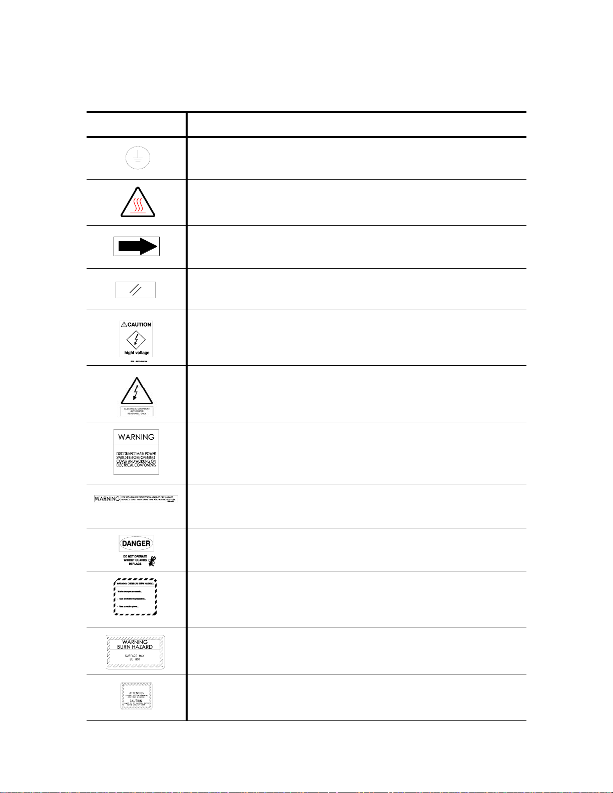
Tables 1-1 and 1-2 contain symbols which may be on your Basil 3500 Cage and Bottle Washer components:
Table 1-1. Definition of Symbols on Unit
Symbol Definition
Protective Earth (Ground).
Transfer of Heat, Hot Surface.
Rotation: Direction of Rotation Device.
Reset.
CAUTION. High Voltage.
ELECTRICAL EQUIPMENT.
Authorized Personnel Only.
WARNING.
Disconnect Main Power switch before opening cover and working on
electrical components.
WARNING.
For continued protection against fire hazard replace only with same type
and rating of fuse.
DANGER.
Do not Operate Without Guards in Place.
WARNING! Chemical Burn Hazard:
Washer detergents are caustic...
Read and follow the precautions...
Wear protective gloves...
WARNING. Burn Hazard.
Surface May Be Hot.
CAUTION.
Always Cut OFF Electrical Supply Before Doing Any Repair.
Safety Precautions Operator Manual 122998-741
1-3

Table 1-2. Definition of Symbols on Identification Nameplate
Symbol Definition
MODEL Model Number of The Unit.
S/N Serial Number of The Unit.
YEAR Year of Manufacture of The Unit.
kVA Kilovolt-Ampere.
V_~ Volt, Number of Phase (3 or 1[blank]), Alternate Current.
A Amperage.
Hz Hertz – Frequency of The Unit.
WIRE Number of Wires In The Electrical Cable (Ground Not Included).
PE Protective Ground Wire.
1-4
122998-741 Operator Manual Safety Precautions

INSTALLATION
IMPORTANT: A listing of the Safety Precautions to be observed when operating this Cage and Bottle
Washer can be found in S
information.
2
ECTION 1. Do not operate equipment until you have become familiar with this
2.1 Technical
Specifications
2.1.1 Voltage, Amperage and Power Consumption
Complete uncrating and installation instructions, as well as an equipment drawing have been furnished. If any of these documents are
missing or misplaced, contact STERIS giving serial, equipment, and
model numbers of the unit. Replacement copies will be sent to you
promptly.
These specifications are intended to describe technical information
given on nameplate of your washer and to state other relevant information. Check equipment drawing or identification nameplate for
proper voltage and amperage.
Basil® 3500 Cage and Bottle Washer operates on:
• Steam-Heated units:
208 V, 60 Hz, 3-phase;
480 V, 60 Hz, 3-phase.
• Electric-Heated units:
480 V, 60 Hz, 3-phase.
A protective ground is required (Class 1 Equipment).
Maximum currents and power consumptions are indicated on
nameplate.
Main supply voltage not exceeding ± 10% of nominal voltage.
Installation category: Overvoltage Category II.
Always follow local electrical installation codes.
Refer to Uncrating/Installation Instructions (P122996-977) for proper
connection.
Installation Operator Manual 122998-741
2-1

2.1.2 Permissible
Environmental Conditions
This equipment is designated to give optimal results under the following conditions:
Indoor use only;
Altitude of operation up to: 6,267 ft (2,000 m);
Maximum relative humidity is 80% for temperatures up to: 88ºF
(31ºC) decreasing linearly to 50% relative humidity at 104ºF
(40ºC);
Pollution degree 2.
2.1.3 Seismic Anchorage System
2.2 Installation Checklist
A Seismic Anchorage System is available for high risk seismic
zones.
After your washer has been installed by qualified service technicians, complete the following checklist to assure installation is complete and correct. If you desire, contact STERIS and schedule a
technician to test installation and demonstrate proper equipment
operation.
❑ To allow service of unit without shutting off building supply lines,
shutoff valves (not provided by STERIS) for maintenance purposes, are installed on steam and water lines to unit. Shutoff
valves must be capable of being locked in OFF position only.
❑ Disconnect switches (not provided by STERIS) are installed in
electric supply lines near washer and within 10' (3 m) of electrical control box. Disconnect switches must be capable of being
locked in OFF position only.
NOTE: If washer is installed next to other equipment, shut-off
valves and disconnect switch should be placed so that service
can be shut off to one piece of equipment at a time.
❑ Washer is positioned as shown on equipment drawing with
required service clearance space and in relation to building supply lines.
❑ Washer must be installed between two walls with a key-locked
service door so service side is not accessible to operators.
❑ Building steam line provides maximum dynamic steam pressure
and flow rate to washer as specified on equipment drawing.
❑ Drip leg with steam trap installed in steam supply line.
❑ Building hot water line supplies water to washer at pressure and
temperature specified on equipment drawing.
❑ If applicable, building cold water line supplies water to washer at
pressure specified on equipment drawing.
❑ Electrical supply for washer is as specified on equipment draw-
ing.
2-2
122998-741 Operator Manual Installation

❑ Condensate returns are sized as specified on equipment draw-
ing.
❑ Vent connections are sized as specified on equipment drawing.
❑ Recirculation pump pressure is within 25 to 60 psig.
❑ Recirculation pump motor rotating in direction shown by arrow.
❑ Self-cleaning screen assembly functioning properly.
❑ Header drive system functioning properly.
❑ All piping is leak-free.
❑ Chamber sump steam coil functioning properly.
❑ Cabinet joints are completely sealed, no leaks. (For verification,
run machine for half an hour.)
❑ Door safety switch(es) functioning properly.
Installation Operator Manual 122998-741
2-3
COMPONENT IDENTIFICATION
IMPORTANT: A listing of the Safety Precautions to be observed when operating this Cage and Bottle
Washer can be found in S
information.
ECTION 1. Do not operate equipment until you have become familiar with this
3
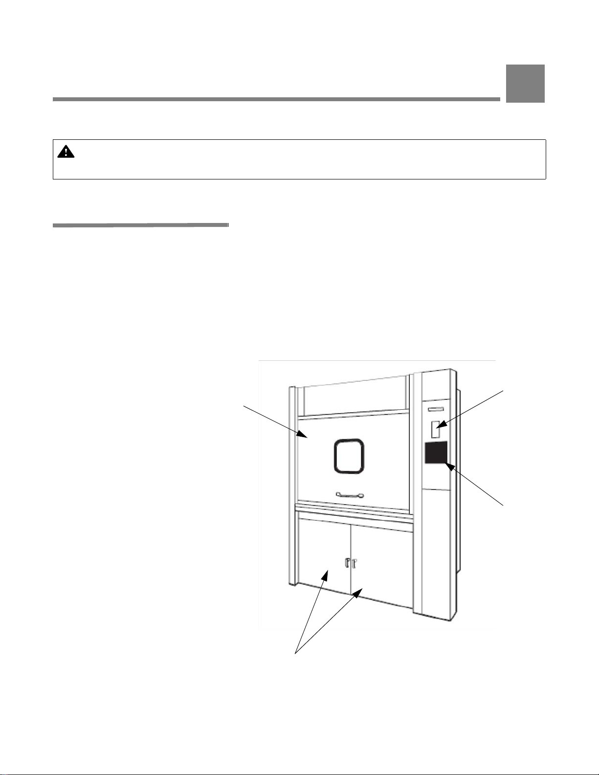
3.1 Component
Identification
Vertical Sliding
Door and Viewing
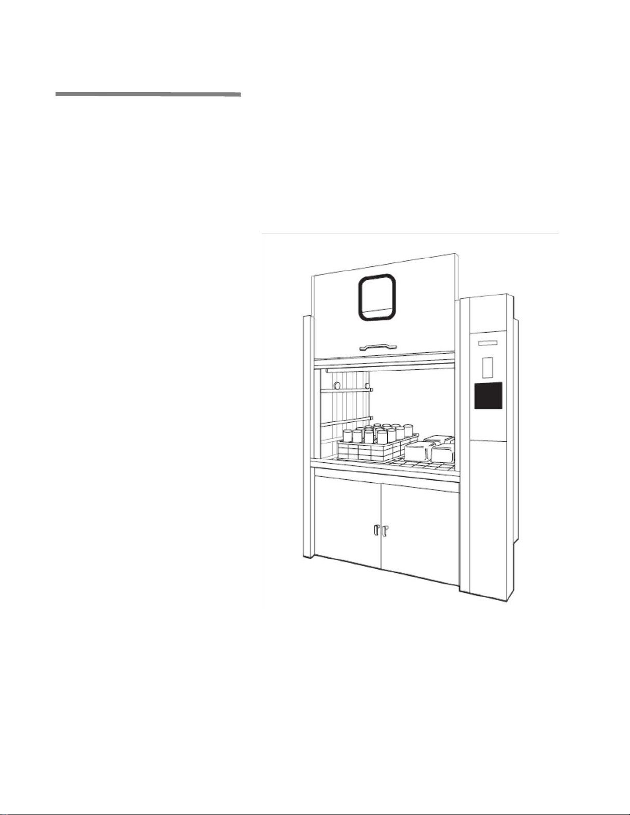
Basil 3500® Cage and Bottle Washers are heavy duty, large capac-
ity hydrospray washers designed for thorough, efficient cleaning of
cages, bottles, debris pans and miscellaneous items used in the
care of laboratory animals.
Washer is equipped with a user-programmable microcomputer control system capable of storing up to twelve treatment cycles to process a wide variety of loads. Computer control system monitors and
automatically controls all cycle operations.
Before operating washer, it is important to become familiar with all
control locations and functions (see Figure 3-1).
Printer
Window
Control
Panel
Service Access Doors
Figure 3-1. Basil 3500 Cage and Bottle Washer Components
Component Identification Operator Manual 122998-741
3-1
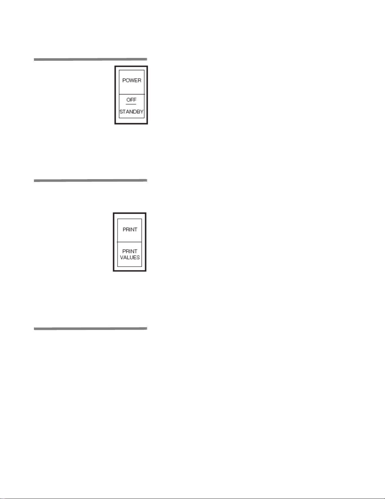
3.2 Power Switch POWER-OFF/STANDBY switch, located behind printer door,
includes
• POWER - Press top portion of rocker switch to initialize controls
• OFF/STANDBY - press bottom portion of rocker switch to initiate
two settings which direct operation of control (see Figure 3-2).
and enable unit operation.
Shutdown cycle and turn off all ac power to control (Standby
mode). While in Standby mode, unit operation is not possible.
NOTE: Control should be placed in Standby mode after last cycle
of day and when washer is not in use for an extended period of
time.
3.3 Printer Printer records pertinent cycle data on 2-1/4 inch wide single-ply
thermal paper. Refer to S
mation on changing paper roll and storing thermal paper.
Printer is located inside of load-side control panel, to the right of load
door.
ECTION 6, ROUTINE MAINTENANCE, for infor-
3.4 Load-Side Control Panel
Printer Function Switch controls the following two printer functions:
• PRINT - Pressing top portion of Printer Function Switch
generates a printout of alkaline and acid detergent setpoints (if
conductivity option) and all RTD temperatures (actual water
temperature).
• PRINT VALUES - Press bottom of Printer Function Switch to
generate a complete printout of all cycle values.
Load-side control panel is used to direct all washer functions. Operator may program specific cycles, review and select cycles, start,
stop, or reset cycle operation, extend or by-pass cycle phases, and
monitor cycle performance from control panel.
Standard load-side control panel includes a printer.
3.4.1 Display Screen Two-line alpha-numeric screen displays cycle program data on
demand, in-cycle performance data, and operator instructions. Display screen also indicates certain abnormal conditions that may
occur during a cycle (see Figure 3-2).
3-2
122998-741 Operator Manual Component Identification
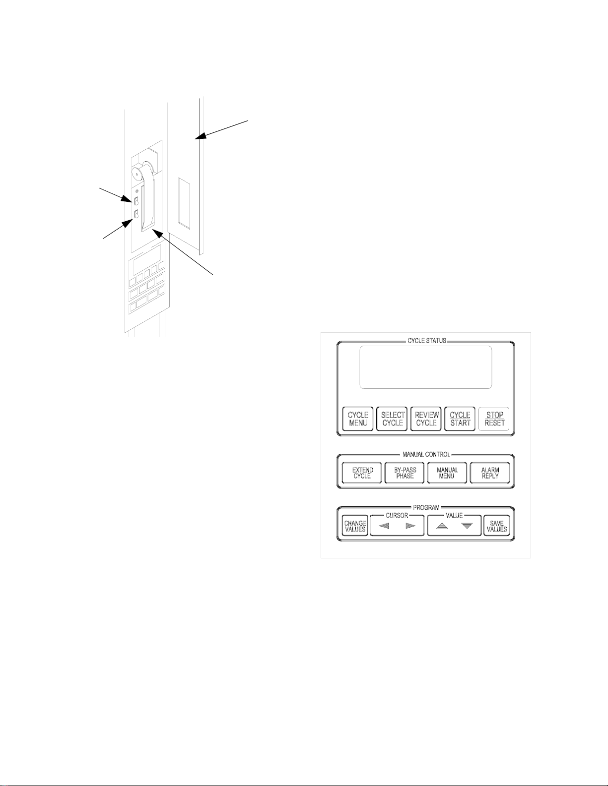
POWER - OFF/
STANDBY
Switch
Printer Function
Switch
Load-Side Control and Printer
Door
Printer
Front Control Panel
Figure 3-2. Control Panel and Printer
Component Identification Operator Manual 122998-741
3-3
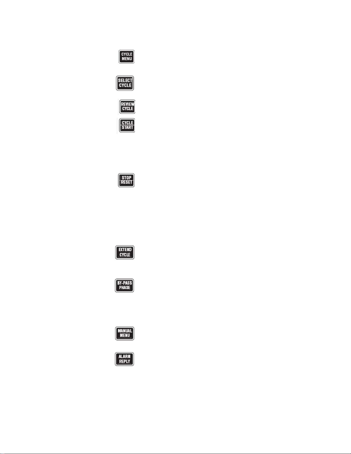
3.4.2 Touch Pads Cycle Status Touch Pads:
• CYCLE MENU - Press to view first cycle menu. Press again to
advance screen to next cycle menu. Three menus are available,
each with four cycles.
• SELECT CYCLE - Press until desired cycle name flashes.
NOTE: When a displayed cycle name or phase value is selected,
corresponding word or digit flashes.
• REVIEW CYCLE - Press to review cycle phases and values
programmed for selected cycle.
• CYCLE/START - Press once to display name of selected cycle.
Press a second time to start cycle.
NOTE: Selected cycle name remains on screen for 5 seconds
after pressing CYCLE/START touch pad once. To start a cycle,
CYCLE/START touch pad must be pressed a second time while
selected cycle name is displayed. If touch pad is not pressed
within 5 seconds, screen automatically returns to Cycle Menu.
• STOP/RESET - Press once to stop operation of a cycle. Press a
second time to abort cycle and return screen to cycle menu.
NOTE: When cycle is stopped, press CYCLE/START touch pad
once to resume cycle operation. Cycle operation resumes at
beginning of interrupted phase function (i.e., filling, recirculating,
draining). When cycle is aborted, cycle operation is discontinued
and cycle must be restarted from the beginning of cycle.
Manual Control Touch Pads:
• EXTEND CYCLE - Press to temporarily increase selected phase
time. On completion of cycle, phase time returns to programmed
set point.
• BY-PASS PHASE - Press to by-pass specific phase in progress
and advance cycle to next phase.
NOTE: BY-PASS PHASE touch pad can only be used when a
cycle is in progress. During cycle, filling and draining functions
cannot be by-passed. In addition, a phase can not be by-passed
if Temperature Guarantee feature is selected for that phase.
• MANUAL MENU - Press to view washer functions which can be
controlled manually.
• ALARM REPLY - Press to turn off alarm buzzer and
acknowledge displayed alarm message. Refer to S
ROUBLESHOOTING, for specific alarm conditions and corrective
T
ECTION 7,
actions.
3-4
122998-741 Operator Manual Component Identification
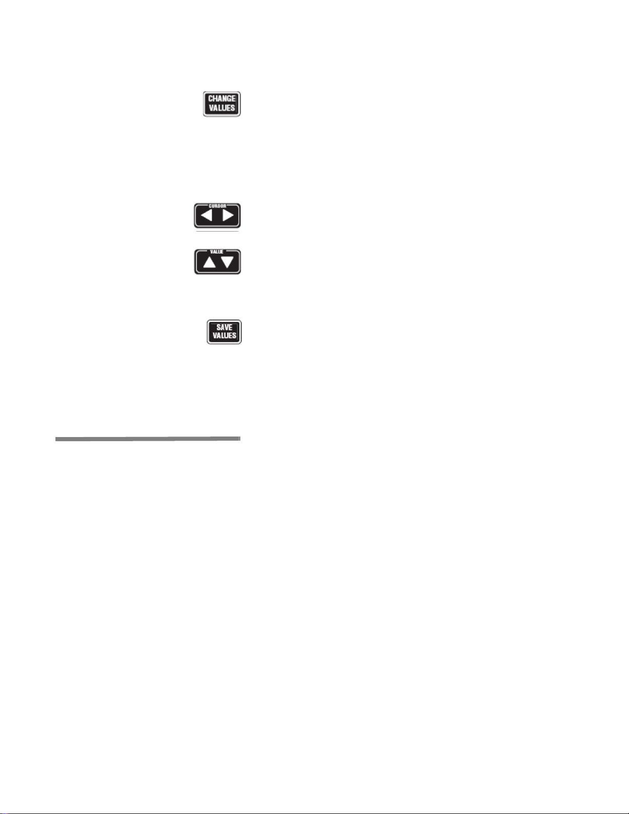
Program Touch Pads:
• CHANGE VALUES - Press to access Change Values mode.
Change Values mode allows authorized operators to change
user-programmable items. Refer to S
ECTION 5, CYCLE AND
CONTROL VALUE PROGRAMMING, for details on Change Values
mode.
NOTE: Examples of user-programmable items include cycle
name, phase temperature, phase time, and questions regarding
phase options (e.g., retention of final rinse water).
• CURSOR Arrows - Press until item to be changed (word, letter,
or number) flashes.
• VALUE Arrows - Depending on item flashing (selected), press
to either toggle between answer selections or scroll through
alphabet and numbers 0 through 9.
NOTE: Alphabet includes characters for an underline and a
space ( ).
• SAVE VALUES - Press to save changes made, exit Change
Values mode and return screen to cycle menu.
3.5 Unload-Side Control Panel
If washer is equipped with a double door for pass-through operation,
an additional control column is installed on unload side of unit. This
second control column is wired directly to main control processor
and includes a control panel. Unload-side control panel features
same touch pads and display as load-side control panel. Display
window concurrently shows same message as shown in display window on operating end of unit.
Standard unload-side control panel does not include a printer.
Component Identification Operator Manual 122998-741
3-5
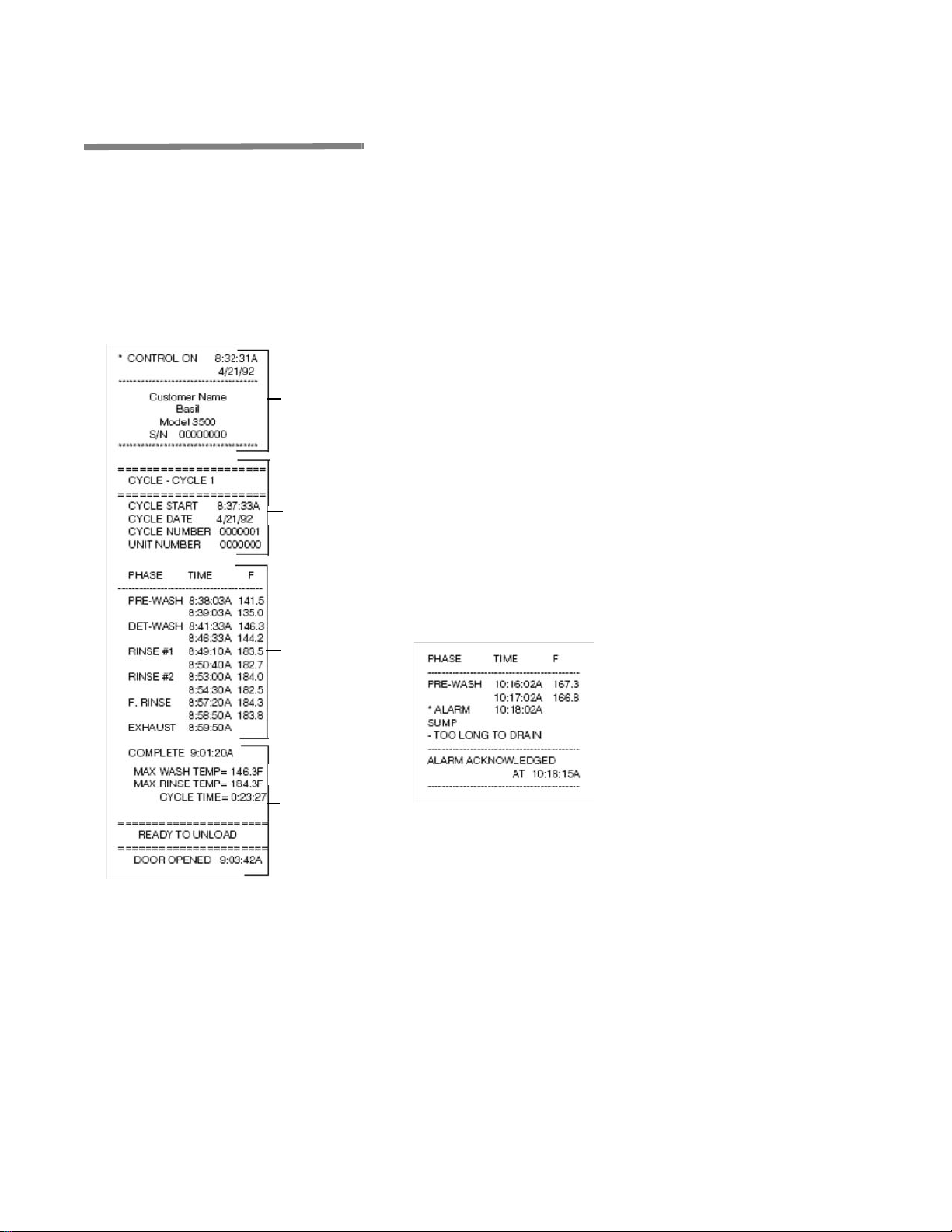
3.6 Typical Printouts Figures 3-3 and 3-4 are examples of typical cycle printouts.
• POWER UP
When Power Switch is set to POWER, generated printout lists
time and date, control was turned on, and unit's serial number.
• CYCLE START
When CYCLE/START touch pad is pressed twice to begin
selected cycle, generated printout lists name of cycle started,
time and date cycle was started, cycle number, and unit
number.
• IN-CYCLE PERFORMANCE
During a cycle, generated printout lists start and end time of
Power
Up
Cycle
Start
each phase, along with actual temperature of solution/water in
chamber sump.
• END-OF-CYCLE PERFORMANCE SUMMARY
At end of a cycle, generated printout lists time cycle was
completed, maximum wash and rinse temperatures reached
during cycle, and total cycle processing time.
• ALARM CONDITION
When an alarm condition occurs, generated printout lists type of
alarm and time it occurred (see Figure 3-4). Once operator
presses ALARM REPLY touch pad, generated printout lists time
when alarm was acknowledged.
In-Cycle
Performance
End-of-Cycle
Performance
Summary
Figure 3-3. Sample Printout
Figure 3-4. Sample Alarm
Printout
3-6
122998-741 Operator Manual Component Identification

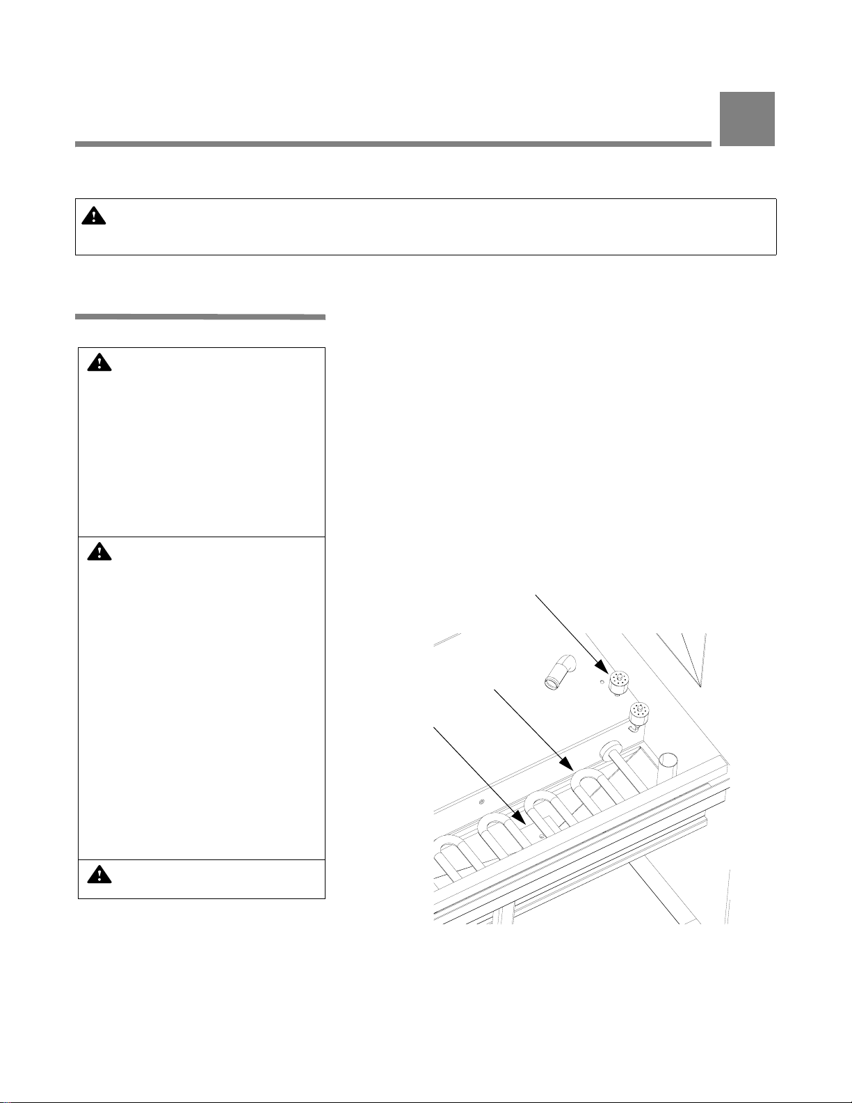
3.7 Oscillating Jet System
Oscillating jet system consists of one oscillating spray header with
machined jets mounted above, below, and on each side of wash
chamber (see Figure 3-5). Machined spray jets are angled to reach
all surfaces of load.
Oscillating jet system travels back and forth along length of chamber
during recirculating/spraying phase function. Jet system is equipped
with a safety clutch that stops movement of oscillating header when
an obstruction is detected.
Chamber door(s) is equipped with a safety switch to stop washer
operation if door is opened during a cycle, and to prevent start of
washer operation if door is not securely closed.
Oscillating jet system is equipped with a mechanical clutch to disengage carriage drive if an obstruction is encountered, preventing
damage to spray header and load items.
Oscillating
Spray Header
Spray Jet
Figure 3-5. Oscillating Jet System
Component Identification Operator Manual 122998-741
3-7

3.8 Safety System Load-side and, if washer is equipped with double-door feature,
unload-side control panels are equipped with red-colored STOP/
RESET touch pads. Press touch pad once to stop cycle operation
and twice to abort cycle.
3.9 Automatic
Detergent Injection
System
WARNING – CHEMICAL BURN
HAZARD:
are caustic and can cause
adverse effects to exposed
tissues. Do not get in eyes,
on skin or attempt to swallow. Read and follow precautions and instructions on
detergent label and in Material Safety Data Sheet
(MSDS) prior to handling
detergent, refilling detergent
container, or servicing detergent injection pump or lines.
Wear appropriate Personal
Protective equipment (PPE)
whenever handling detergent
or servicing detergent pump
or lines.
Washer detergents
Automatic Detergent Injection System includes a peristaltic pump
mounted to washer exterior.
If using alkaline detergent with the injection system, alkaline detergent is automatically injected into chamber sump during Wash treatment of a cycle. Detergent is injected for a programmed time interval
while sump is filling with hot building-supply water.
If using acid detergent with injection system, acid detergent is automatically injected into chamber sump during Acid Wash phase of a
cycle. Detergent is injected for a programmed time interval while
sump is filling.
NOTE: Washer must be equipped with an acid detergent system
option for acid detergent to be used.
3-8
122998-741 Operator Manual Component Identification

3.10 Drain Discharge
Cooldown System with
Cold Water Injection
3.11 Exhaust Fan During unit operation, exhaust fan removes residual vapors from
Washer drain system is piped to automatically cool all drain discharges using building cold water supply.
During draining function of each phase, cold tap water is injected
into washer drain line as washer drain discharges are sent directly to
building drain system.
wash chamber and directs vapors to building exhaust duct.
3.12 Vapor Condensing Exhaust System
Vapor Condensing Exhaust System consists of a vapor condenser,
mounted to side of washer, and an exhaust fan, mounted on top of
washer. Unit width and height are increased by
and 190 mm).
During unit operation, residual vapors are automatically removed
from wash chamber and directed to vapor condenser. Vapors are
then cooled, condensed, and directed to building drain system.
14" and 7.5" (355 mm
3.13 Heat Exchanger Washer is equipped with a steam heat exchanger and valving sys-
tem to preheat incoming fill water, reducing normal water/solution
heat-up time.
System is fully automatic and works during filling phase of all cycle
treatments.
Component Identification Operator Manual 122998-741
3-9
OPERATING INSTRUCTIONS
IMPORTANT: A listing of the Safety Precautions to be observed when operating this Cage and Bottle
Washer can be found in S
information.
ECTION 1. Do not operate equipment until you have become familiar with this
4
4.1 Before Operating Washer
WARNING – SLIPPING HAZARD:
To prevent slips, keep floor
dry. Promptly clean up any
spills or drippage. If spills or
drippage are detergents or
other chemicals, follow
safety precautions and handling procedures set forth on
detergent or chemical label
and/or Material Safety Data
Sheet (MSDS).
WARNING – CHEMICAL
BURN HAZARD: Washer
detergents are caustic and
can cause adverse effects to
exposed tissues. Do not get
in eyes, on skin, or attempt to
swallow. Read and f ollow precautions and instructions on
detergent label and in Material Safety Data Sheet (MSDS)
prior to handling detergent,
refilling detergent container,
or servicing detergent injection pump or lines. Wear
appropriate Personal Protective Equipment (PPE) whenever handling detergent or
servicing detergent injection
pump and lines.
WARNING – BURN HAZARD:
Pipes may be extremely hot.
1. Verify building electrical supply disconnect switch (circuit
breaker) is positioned to ON. Verify steam and water supply
valves are open.
2. Open chamber door and verify wash chamber is empty.
3. Verify vortex plate, located under load grating, is free of debris
(see Figure 4-1).
4. Verify detergent supply (remotely located). Ensure supply hose
is correctly placed in detergent container and detergent pump is
turned on.
NOTE: Always use a non-foaming detergent for effective cleaning
and proper pump and water level control operation. To achieve
maximum cleaning efficien cy, sele ct det ergent appro priate to soil
type being processed.
Water Level
Sump Coil
Vortex Plate
Figure 4-1. Vortex Plate
Operating Instructions Operator Manual 122998-741
4-1
4.2 Loading Unit 1. Open chamber door and load wash chamber (see Figure 4-2).
Ensure all cages, bottles, etc. are correctly positioned on load
grating or in an accessory rack.
2. Verify clearance space on both sides of loaded items permits
unobstructed movement of oscillating jet system.
3. Close chamber door(s) securely.
NOTE: Door safety switch prevents cycle operation unless
door(s) is closed.
Figure 4-2. Loading Washer
4-2
122998-741 Operator Manual Operating Instructions

4.3 Cycle Operation Basil
puter control capable of storing parameters for twelve distinct
cycles. Authorized operators have capability of customizing/programming all cycles to meet specific washing needs. Cycle programming may be limited by access code to assure process
integrity. For instructions on cycle programming or changing cycle
parameters, refer to S
MING.
On initial receipt of washer, each cycle is set with a basic cycle consisting of six sequential treatments – Pre-Wash, Wash, First Rinse,
Second Rinse, Final Rinse, and Exhaust. See Table 4-1 for phase
values of demonstration cycle.
Cycle Treatment Time (minutes) Temperature
®
3500 Cage and Bottle Washer is equipped with a microcom-
ECTION 5, CYCLE AND CONTROL VALUE PROGRAM-
Table 4-1. Demonstration Cycle Treatment Values
Pre-wash 1:00 HTW
Wash 5:00 140ºF (60ºC)
Rinse1 1:30 180ºF (82ºC)
Rinse 2 1:30 180ºF (82ºC)
Final Rinse 1:30 180ºF (82ºC)
Exhaust 1:30 N/A
HWT = Hot Tap Water (130ºF [54ºC] minimum)
To begin cycle operation:
1. Set POWER-OFF/STANDBY Switch, located behind printer
door, to POWER. Unit name temporarily appears on screen,
then display shows first cycle menu:
CYCLE 1 CYCLE 2
CYCLE 3 CYCLE 4
__Indicates flashing position.
... and printer records:
* CONTROL ON 8:32:31A
4/21/92
***************************************
2. Press CYCLE MENU touch pad until desired cycle menu
appears on screen:
CYCLE 9 CYCLE 10
CYCLE 11 CYCLE 12
__Indicates flashing position.
Operating Instructions Operator Manual 122998-741
4-3
WARNING – BURN HAZARD:
• Do not reach into sump.
• Wear appropriate Personal Protective Equipment (PPE) including
gloves and face protection, open door slowly
and allow chamber and
load to cool when cycle is
complete. Hot steam may
escape through door
opening if door is fully
opened after cycle is complete.
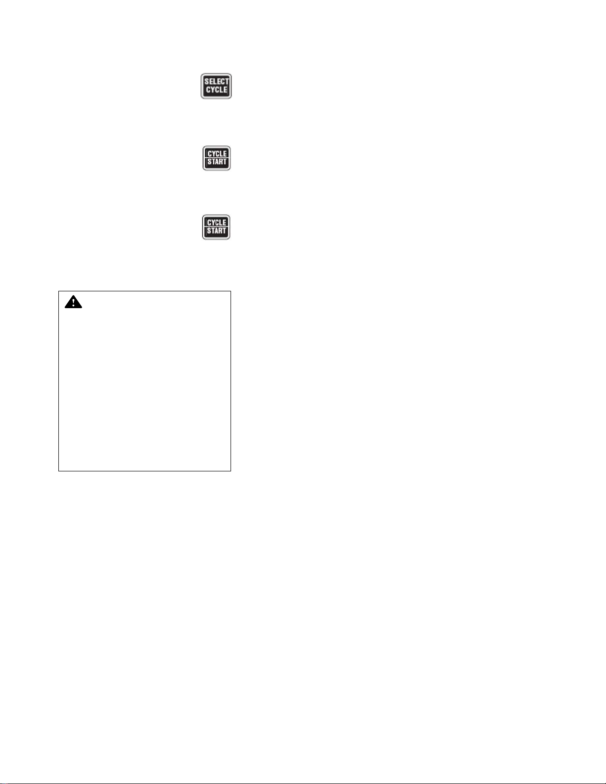
3. Press SELECT CYCLE touch pad until desired cycle name
flashes:
CYCLE 9 CYCLE 10
CYCLE 11 CYCLE 12
__Indicates flashing position.
4. When desired cycle name is flashing, press CYCLE/START
touch pad. Selected cycle name appears on screen and
remains displayed for five seconds:
PRESS START TO
PROCESS - CYCLE 10
5. To start selected cycle, press CYCLE/START touch pad, a sec-
ond time while selected cycle name is displayed on screen.
NOTE: If touch pad is not pressed a second time while selected
cycle name is displayed, screen automatically returns to cycle
menu.
Once selected cycle is started, printer records:
======================
CYCLE - CYCLE 10
======================
CYCLE START 10:16:20A
CYCLE DATE 4/21/92
CYCLE NUMBER 0000002
UNIT NUMBER 0000000
PHASE TIME F
----------------------------------------------
6. Washer automatically progresses through selected cycle as
described in the following section.
NOTE: During cycle, note the following:
1) Time displayed on screen counts down time remaining for
cycle phase in progress. If Temperature Guarantee feature is
selected, time displayed for that phase will only count down
when solution/water temperature in chamber sump is equal to
or greater than set point.
2) Cycle operation may be halted at any time by pressing STOP/
RESET once. To resume cycle operation at beginning of interrupted phase function (i.e., fill, recirculate, drain), press
CYCLE/START. To abort cycle operation, press STOP/
RESET a second time.
4-4
122998-741 Operator Manual Operating Instructions

4.3.1 Pre-Wash (Standard) 1. Hot water, from building supply, fills sump until set water level is
attained:
NOTE: Sump may contain rinse water retained from previous
cycle.
CYCLE 10 135.7 F
PREWASH FILL 2:00
WARNING – BURN HAZARD:
Water discharge may be
extremely hot.
2. Pre-Wash water recirculates through oscillating jet system for
programmed time:
CYCLE 10 139.5 F
PREWASH 1:00
3. Printer records time and water temperature in chamber sump at
beginning and end of recirculation:
PRE-WASH 10:18:15A 139.5
10:19:15A 135.0
*******************************************
4.3.2 pH Neutralization 1. pH analyzer is initialized:
STANDBY NEUTRALIZING SUMP
2. pH analyzer verifies that value is within limits:
CHECKING pH
pH = XX.XXX
3. If pH is too low, while injecting, acid neutralizer is injected to
compensate:
pH TOO LOW
INJECTING ACID NEUT.
4. Water-Acid neutralizer solution is mixed:
pH TOO LOW
MIXING WATER
5. If pH is too high, while injecting, alkaline neutralizer is injected to
compensate:
pH TOO HIGH
INJECTING ALK. NEUT.
... alternating with:
pH TOO HIGH
MIXING WATER
Operating Instructions Operator Manual 122998-741
4-5

4.3.3 Alkaline Wash Phase Hot water from building supply fills sump. If temperature is guaran-
teed, actual sump temperature alternates with guaranteed set temperature:
CYCLE 10 (G=)137.4 F
ALK. WASH FILL 2:00
If conductivity option is present:
WARNING – BURN HAZARD:
Water discharge may be
extremely hot.
1. Water is heated while recirculating. If temperature is guaranteed
actual sump temperature alternates with guaranteed set
temperature.
NOTE: Control alternates between these display screens every
four seconds during recirculation. Displayed time will only count
down when solution temperature is equal to or greater than set
point.
CYCLE 10 (G=)141.5 F
RECIRC/HEATING 5:00
2. Alkaline detergent is injected into sump. If temperature is guaranteed, actual sump temperature alternates with guaranteed set
temperature.
NOTE: Control alternates between these display screens every
four seconds during recirculation. Displayed time will only count
down when solution temperature is equal to or greater than set
point.
CYCLE 10 (G=)141.5 F
INJECTING ALK. 5:00
3. Detergent solution is recirculated through oscillating jet system
for programmed amount of time. If temperature is guaranteed,
actual sump temperature alternates with guaranteed set temperature.
NOTE: Control alternates between these display screens every
four seconds during recirculation. Displayed time will only count
down when solution temperature is equal to or greater than set
point.
CYCLE 10 (G=)140.0 F
ALKALINE WASH 5:00
4. Printer records time and solution temperature in chamber sump
at beginning and end of recirculation.
ALK. WASH10:21:55A 141.5
10:26:55A 140.2
*************************************
4.3.4 Time-Based pH
Neutralization (Option)
Alkaline neutralizer is injected during programmed amount of time. If
temperature is guaranteed, actual sump temperature alternates with
guaranteed set temperature.
CYCLE 10 (G=)167.8 F
ALK NEUTRALIZE 2:00
4-6
122998-741 Operator Manual Operating Instructions

4.3.5 Controller-Driven pH Neutralization (Option)
1. pH analyzer is initialized:
STANDBY
NEUTRALIZING SUMP
2. pH analyzer verifies that value is within limits programmed:
CHECKING pH
pH = XX.XXX
3. If pH is too low, while injecting, acid neutralizer is injected to
compensate:
pH TOO LOW
INJECTING ACID NEUT.
4. Water-Acid neutralizer solution is mixed:
pH TOO LOW
MIXING WATER
5. If pH is too high, while injecting, alkaline neutralizer is injected to
compensate:
pH TOO HIGH
INJECTING ALK. NEUT.
6. Water-Alkaline neutralizer solution is mixed:
pH TOO HIGH
MIXING WATER
7. Sump water is pumped to drain. If temperature is guaranteed,
actual sump temperature alternates with guaranteed set temperature.
Operating Instructions Operator Manual 122998-741
4-7

4.3.6 Acid Wash Phase (Option)
WARNING – BURN HAZARD:
Water discharge may be
extremely hot.
Hot water, from building supply fills sump. If temperature is guaranteed, actual sump temperatures alternates with guaranteed set temperature.
NOTE: Control alternates betw een these display screens every fo ur
seconds during recirculation. Displayed time will only count down
when solution temperature is equal to or greater than set point.
CYCLE 10 (G=)137.4 F
ACIDWASH FILL 2:00
• If conductivity option is present:
1. Water is heated while recirculating. If temperature is guaranteed,
actual sump temperature alternates with guaranteed set
temperature.
NOTE: Control alternates between these display screens every
four seconds during recirculation. Displayed time will only count
down when solution temperature is equal to or greater than set
point.
CYCLE 10 (G=)141.5 F
RECIRC/HEATING 5:00
2. Acid detergent is injected into sump. If temperature is guaranteed, actual sump temperature alternates with guaranteed set
temperature.
NOTE: Control alternates between these display screens every
four seconds during recirculation. Displayed time will only count
down when solution temperature is equal to or greater than set
point.
CYCLE 10 (G=)141.5 F
INJECTING ACID 5:00
3. Detergent solution is recirculated through oscillating jet system
for programmed amount of time. If temperature is guaranteed,
actual sump temperature alternates with guaranteed set temperature*.
NOTE: Control alternates between these display screens every
four seconds during recirculation. Displayed time will only count
down when solution temperature is equal to or greater than set
point.
CYCLE 10 (G=)140.0 F*
ACID WASH 5:00
4. Printer records time and solution temperature in chamber sump
at beginning and end of recirculation:
ACID WASH 10:21:55A141.5
10:26:55A140.2
****************************************
4-8
122998-741 Operator Manual Operating Instructions

5. Load is soaked in acid solution for programmed amount of time.
If temperature is guaranteed, actual sump temperature alternates with guaranteed set temperature:
CYCLE 10 (G=)167.8 F
ACID SOAK 2:00
4.3.7 Time-Based pH
Neutralization (Option)
4.3.8 Controller-Driven pH Neutralization (Option)
Acid neutralizer is injected during programmed amount of time. If
temperature is guaranteed, actual sump temperature alternates with
guaranteed set temperature.
CYCLE 10 (G=)167.8 F
ACID NEUTRALIZ 2:00
1. pH analyzer is initialized:
STANDBY
NEUTRALIZING SUMP
2. pH analyzer verifies that value is within limits:
CHECKING pH
pH = XX.XXX
3. If pH is too low, while injecting, acid neutralizer is injected to
compensate:
pH TOO LOW
INJECTING ACID NEUT.
4. Water-Acid neutralizer solution is mixed:
pH TOO LOW
MIXING WATER
5. If pH is too high, while injecting, alkaline neutralizer is injected to
compensate:
pH TOO HIGH
INJECTING ALK. NEUT.
6. Sump water is pumped to drain. If temperature is guaranteed,
actual sump temperature alternates with guaranteed set temperature:
CYCLE 10 (G=)128.5 F
ACID DRAIN 1:00
Operating Instructions Operator Manual 122998-741
4-9

4.3.9 Rinse 1 Phase 1. Hot water, from building supply, fills sump. If temperature is
guaranteed, actual sump temperature alternates with
guaranteed set temperature.
WARNING – BURN HAZARD:
Water discharge may be
extremely hot.
NOTE: Control alternates between these display screens every
four seconds during recirculation. Displayed time will only count
down when solution temperature is equal to or greater than set
point.
CYCLE 10 (G=)137.4 F
RINSE 1 FILL 2:00
2. Rinse 1 water is recirculated through oscillating jet system for
programmed amount of time. If temperature is guaranteed,
actual sump temperature alternates with guaranteed set temperature.
NOTE: Control alternates between these display screens every
four seconds during recirculation. Displayed time will only count
down when solution temperature is equal to or greater than set
point.
Display shows:
CYCLE 10 (G=)140.0 F
RINSE 1 5:00
3. Printer records time and solution temperature in chamber sump
at beginning and end of recirculation:
4.3.10 Controller-Driven pH Neutralization (Option)
RINSE 1 10:21:55A 141.5
10:26:55A 140.2
****************************************
1. pH analyzer is initialized:
STANDBY
NEUTRALIZING SUMP
2. pH analyzer verifies that value is within limits:
CHECKING pH
pH = XX.XXX
3. If pH is too low, while injecting, acid neutralizer is injected to
compensate:
pH TOO LOW
INJECTING ACID NEUT.
4. Water-Acid neutralizer solution is mixed:
pH TOO LOW
MIXING WATER
5. If pH is too high, while injecting, alkaline neutralizer is injected to
compensate:
pH TOO HIGH
INJECTING ALK. NEUT.
4-10
122998-741 Operator Manual Operating Instructions

6. Water-Alkaline neutralizer solution is mixed:
pH TOO HIGH
MIXING WATER
7. Sump water is pumped to drain. If temperature is guaranteed,
actual sump temperature alternates with guaranteed set temperature.
CYCLE 10 (G=)128.5 F
RINSE 1 DRAIN 1:00
4.3.11 Rinse 2 Phase 1. Hot water from building supply fills sump. If temperature is
guaranteed, actual sump temperature alternates with
guaranteed set temperature.
WARNING – BURN HAZARD:
Water discharge may be
extremely hot.
NOTE: Control alternates between these display screens every
four seconds during recirculation. Displayed time will only count
down when solution temperature is equal to or greater than set
point.
CYCLE 10 (G=)137.4 F
RINSE 2 FILL 2:00
2. Rinse 2 solution is recirculated through oscillating jet system for
programmed amount of time. If temperature is guaranteed,
actual sump temperature alternates with guaranteed set temperature.
NOTE: Control alternates between these display screens every
four seconds during recirculation. Displayed time will only count
down when solution temperature is equal to or greater than set
point.
CYCLE 10 (G=)140.0 F
RINSE 2 5:00
3. Printer records time and solution temperature in chamber sump
at beginning and end of recirculation.
RINSE 2 10:21:55A 141.5
10:26:55A 140.2
**************************************
Operating Instructions Operator Manual 122998-741
4-11

4.3.12 Controller-Driven pH Neutralization (Option)
1. pH analyzer is initialized.
STANDBY
NEUTRALIZING SUMP
2. pH analyzer verifies that value is within limits:
CHECKING pH
pH = XX.XXX
3. If pH is too low, while injecting, acid neutralizer is injected to
compensate:
pH TOO LOW
INJECTING ACID NEUT.
4. Water-Acid neutralizer solution is mixed:
pH TOO LOW
MIXING WATER
5. If pH is too high, while injecting, alkaline neutralizer is injected to
compensate:
pH TOO HIGH
INJECTING ALK. NEUT.
6. Water-Alkaline neutralizer solution is mixed.
pH TOO HIGH
MIXING WATER
7. Sump water is pumped to drain. If temperature is guaranteed,
actual sump temperature alternates with guaranteed set temperature.
CYCLE 10 (G=)128.5 F
RINSE 2 DRAIN 1:00
4-12
122998-741 Operator Manual Operating Instructions

4.3.13 Final Rinse Phase 1. Hot water, from building supply, fills sump. If temperature is
guaranteed, actual sump temperature alternates with
guaranteed set temperature.
WARNING – BURN HAZARD:
Water discharge may be
extremely hot.
NOTE: Control alternates between these display screens every
four seconds during recirculation. Displayed time will only count
down when solution temperature is equal to or greater than set
point.
CYCLE 10 (G=)137.4 F
F. RINSE FILL 2:00
2. Final Rinse solution is recirculated through oscillating jet system
for programmed amount of time. If temperature is guaranteed,
actual sump temperature alternates with guaranteed set temperature.
NOTE: Control alternates between these display screens every
four seconds during recirculation. Displayed time will only count
down when solution temperature is equal to or greater than set
point.
CYCLE 10 (G=)140.0 F
FINAL RINSE 5:00
3. Printer records time and solution temperature in chamber sump
at beginning and end of recirculation.
F. RINSE 10:21:55A 141.5
10:26:55A 140.2
***************************************
4.3.14 Controller-Driven pH Neutralization (Option)
1. pH analyzer is initialized:
STANDBY
NEUTRALIZING SUMP
2. pH analyzer verifies to see if value is within limits:
CHECKING pH
pH = XX.XXX
3. If pH is too low, while injecting, acid neutralizer is injected to
compensate:
pH TOO LOW
INJECTING ACID NEUT.
4. Water-Acid neutralizer solution is mixed:
pH TOO LOW
MIXING WATER
5. If pH is too high, while injecting, alkaline neutralizer is injected to
compensate:
pH TOO HIGH
INJECTING ALK. NEUT.
6. Water-Alkaline neutralizer solution is mixed:
Operating Instructions Operator Manual 122998-741
4-13

pH TOO HIGH
MIXING WATER
7. Sump water is pumped to drain. If temperature is guaranteed,
actual sump temperature alternates with guaranteed set temperature:
CYCLE 10 (G=)128.5 F
F. RINSE DRAIN 1:00
4.3.15 Exhaust Phase 1. Washer stands idle for programmed time allowing residual
vapors to exhaust from wash chamber to room:
CYCLE 10
EXHAUST 1:30
2. Printer prints time at completion of phase:
EXHAUST 10:38:05A
**************************************
NOTE: Customer must connect exhaust vent to building exhaust
system to prevent directly exhausting vapors to room.
4.3.16 Cycle Complete
WARNING – BURN HAZARD:
Wear appropriate Personal
Protective Equipment (PPE)
including gloves and face
protection, open door slowly,
and allow chamber and load
to cool when cycle is complete. Hot steam may escape
through door opening if door
is fully opened after cycle is
complete.
WARNING – SLIPPING HAZARD: To prevent slips, keep
floor dry. Promptly clean up
any spills or drippage. If
spills or drippage are detergents or other chemicals, follow safety precautions and
handling procedures set forth
on detergent or chemical
label and/or Material Safety
Data Sheet (MSDS).
1. Alarm buzzer sounds and an operator instruction is displayed.
Alarm buzzer can be silenced by pressing ALARM REPLY
touch pad or opening chamber door(s). Instruction remains on
screen until door(s) is opened.
PLEASE OPEN DOOR
AND REMOVE THE LOAD
... then printer records:
COMPLETE 10:39:35A
MAX WASH TEMP= 141.5F
MAX RINSE TEMP= 180.8F
CYCLE TIME= 0:23:15
======================
= READY TO UNLOAD =
=======================
2. Cautiously open chamber door to vent remaining steam vapors.
Allow chamber to cool a few minutes before removing load. Display screen returns to cycle menu:
CYCLE 9 CYCLE 10
CYCLE 11 CYCLE 12
__Indicates flashing position.
...and printer records:
DOOR OPENED 10:42:10A
************************************
4-14
122998-741 Operator Manual Operating Instructions

4.4 Stop Cycle Operation
1. Press STOP/RESET touch pad to immediately halt operation of
cycle in progress. Display screen indicates cycle is/was
stopped:
CYCLE 4
CYCLE STOPPED!
... and printer records:
RINSE 1 2:54:48P 181.3
* CYCLE STOPPED 2:55:00P
*******************************************
2. Press CYCLE/START touch pad to resume cycle operation at
beginning of interrupted phase function (i.e., fill, recirculate,
drain). Phase resets to beginning of interrupted function,
CYCLE 4 180.5 F
RINSE 1 1:30
... and printer records:
RINSE 1 2:55:22P 181.3
*ALARM 2:55:00P
STOP BUTTON PRESSED!
****************************************
4.5 Abort Cycle Operation
1. Press STOP/RESET touch pad halt cycle in progress.
2. Press STOP/RESET touch pad a second time to abort cycle.
Display shows:
CYCLE 4
CYCLE ABORTED!
... and printer records:
* CYCLE ABORTED 2:55:00P
**************************************
3. Control automatically returns screen to selected cycle menu:
CYCLE 1 CYCLE 2
CYCLE 3 CYCLE 4
__Indicates flashing position.
Operating Instructions Operator Manual 122998-741
4-15

4.6 Shutdown Procedure
At the end of a work session, washer should be shut down and
cleaned thoroughly. Refer to S
ECTION 6, ROUTINE MAINTENANCE, for
complete cleaning instructions and scheduled minor maintenance.
1. Access Manual Control mode, and drain washer sump.
2. Position POWER-OFF/STANDBY switch to OFF/STANDBY.
3. Position building electrical disconnect switch (circuit breaker) to
OFF and close building supply valves.
4. Clean unit as described in S
ECTION 6, ROUTINE MAINTENANCE.
5. Ensure building electrical disconnect switch is positioned to ON
after completion of cleaning and minor maintenance procedures.
NOTE: Leaving disconnect switch in OFF position overnight will
shorten life span of battery backed-up control memory.
4-16
122998-741 Operator Manual Operating Instructions

4.7 Manual Control Mode
User or service technician can manually control certain washer functions by accessing Manual Control Mode. Manual Control Mode is
accessible from Operating Mode when washer is not in cycle.
Figure 4-3. Manual Control Mode Flow Chart
Operating Instructions Operator Manual 122998-741
4-17

4.7.1 Accessing Manual Control Mode
To access Manual Control Mode:
1. From Cycle Menu, press MANUAL MENU touch pad:
CYCLE 1 CYCLE 2
CYCLE 3 CYCLE 4
__Indicates flashing position.
2. Display momentarily shows:
MANUAL CONTROL MODE
After 4 seconds, display will show Manual Control Menu:
FILL DRAIN
PUMP/DRV DRIVE
__Indicates flashing position.
3. To perform specific manual functions, refer to descriptions
included in this section, titled same as shown on display screen.
FILL selection allows manual filling of chamber sump. DRAIN
selection allows manual draining of chamber sump. PUMP/DRV
selection allows manual operation of recirculation pump(s) and
oscillating jet system. DRIVE selection allows manual operation
of carriage drive system while chamber door is open or closed.
4.7.2 Fill To access Manual Fill function:
1. At Manual Control Menu, press SELECT CYCLE touch pad until
FILL is flashing and press CYCLE/START touch pad. Display
shows:
FILLING SUMP...
PRESS STOP TO ABORT
NOTE: If necessary, manual functions can be aborted at any t ime
by pressing STOP/RESET touch pad.
2. When sump is full, display shows:
SUMP FULL
3. After a delay of 2 seconds, display returns to Manual Control
Menu:
FILL DRAIN
PUMP/DRV DRIVE
__Indicates flashing position.
4-18
122998-741 Operator Manual Operating Instructions

4.7.3 Drain To access Manual Drain functions:
1. From Manual Control Menu, press SELECT CYCLE touch pad
until DRAIN is flashing. Display shows:
FILL DRAIN
PUMP/DRV DRIVE
__Indicates flashing position.
2. To drain sump manually:
If sump is not already full, display shows:
FILLING SUMP...
PRESS STOP TO ABORT
3. Once sump is full, display shows:
SUMP FULL
4. After 3 second delay, jet valve(s) closes, sump drain valve(s)
open, and display shows:
DRAINING SUMP...
PRESS STOP TO ABORT
5. Pump will run for DRAIN TIME, then display shows:
SUMP EMPTY
4.7.4 Pump/DRV To operate recirculation pump(s) and oscillating jet system manually:
1. From Manual Control Menu, press SELECT CYCLE touch pad
until PUMP/DRV is flashing. Display shows:
FILL DRAIN
PUMP/DRV DRIVE
__Indicates flashing position.
2. With PUMP/DRV flashing, press CYCLE/START touch pad. If
sump is not full, display shows:
FILLING SUMP...
PRESS STOP TO ABORT
3. Once sump is full, display shows:
SUMP IS FULL
4. After a delay of 2 seconds, display shows:
PUMPING/DRIVING...
PRESS STOP TO ABORT
NOTE: Recirculation pump(s) and oscillating jet system will
continue to operate until STOP/RESET is pressed.
5. Press STOP/RESET touch pad when done. Display returns to
Manual Control Menu:
FILL DRAIN
PUMP/DRV DRIVE
__Indicates flashing position.
Operating Instructions Operator Manual 122998-741
4-19

4.7.5 Drive To operate carriage drive system manually:
1. From Manual Control Menu, press SELECT CYCLE touch pad
until DRIVE is flashing. Display shows:
FILL DRAIN
PUMP/DRV DRIVE
__Indicates flashing position.
2. With DRIVE flashing, press CYCLE/START touch pad. Display
shows:
DRIVING...
PRESS STOP TO ABORT
3. Carriage will oscillate with doors open or closed.
NOTE: Carriage will continue to oscillate until STOP/RESET is
pressed.
4. Press STOP/RESET touch pad when done. Display returns to
Manual Control Menu:
FILL DRAIN
PUMP/DRV DRIVE
4-20
122998-741 Operator Manual Operating Instructions

CYCLE AND CONTROL VALUE PROGRAMMING
IMPORTANT: A listing of the Safety Precautions to be observed when operating this Cage and Bottle
Washer can be found in S
information.
ECTION 1. Do not operate equipment until you have become familiar with this
5
5.1 Program Touch Pads
Microcomputer control of Basil® 3500 Cage and Bottle Washer
allows adjustment of previously programmed cycles to process different types of loads. All program changes are made using Program
touch pads on washer control panel (see Figure 5-1).
Figure 5-1. Program Touch Pads
Program touch pads function as follows:
• CHANGE VALUES - press to access Change Values mode.
• CURSOR arrows - (left or right) press until item to be changed
(word, letter, or number) flashes.
• VALUE arrows - (up or down) depending on item flashing
(selected), press to either toggle between answer selections or
scroll through alphabet and numbers 0 through 9.
NOTE: Alphabet includes characters for an underline (_) and a
space ( )
• SAVE VALUES - press to save changes made, exit Change
Values mode and return screen to cycle menu.
5.2 Change Values Mode
Cycle and Control Value Programming Operator Manual 122998-741
Change Values mode allows authorized operators to change both
cycle values and general operating values. In Change Values mode,
cycles may be altered and saved as custom cycle programs to meet
specific washing needs. See Table 5-1, C
for programmable values accessible through Change Values mode.
YCLE DESCRIPTION CHART,
5-1

REVISION 0 (2004 12 02)
FINAL RINSE
RECIRCULATED
RINSE 1 RINSE 2
ACID SOAK
00:00TO99:99
00:00TO49:99
00:00TO49:99
00:00TO49:99
00:00TO99:99
(60°C)
140.0°F
HEATED
HEATED
70.0F (21.1°C)
(60°C)
140.0°F
HEATED
HEATED
70.0F (21.1°C)
HEATED
70.0F (21.1°C)
TO
TO
180°F (82°C)
185°F (85°C)
TO
TO
180°F (82°C)
185°F (85°C)
TO
185°F (85°C)
X
Basil 3500 Cage and Bottle Washer - Cycle Description Chart
00:00TO49:99
ALKALINE WASH ACID WASH
PRE-WASH EXHAUST
RECIRCULATED
00:00TO49:99
00:00TO99:99
01:00 05:00 05:00 01:30 01:30 01:30 01:30 01:30
DEFAULT SELECT DEFAULT SELECT DEFAULT SELECT DEFAULT SELECT DEFAULT SELECT DEFAULT SELECT DEFAULT SELECT DEFAULT SELECT
(1)
TIME:
PHASE: RECIRCULATED RECIRCULATED RECIRCULATED RECIRCULATED
CIRCULATION
PUMP DETERGENT DETERGENT
INJECTION ALKALINE ACID
Table 5-1. Cycle Description Chart
TO
HEATED
185°F (85°C)
70.0F (21.1°C)
TO
HEATED
185°F (85°C)
70.0F (21.1°C)
(60°C) (60°C) (82.2°C) (82.2°C) (82.2°C)
X X X X X X X X
OR HTW HEATED HEATED HEATED HEATED HEATED
AIR TEMP 140.0°F 140.0°F 180.0°F 180.0°F 180.0°F
SELECTION: PUMP PUMP
WATER TYPE
CYCLE 1
X X X X X X X X
CYCLE 2
X X X X X X X X
CYCLE 3
X X X X X X X X
CYCLE 4
X X X X X X X X
CYCLE 5
X X X X X X X X
CYCLE 6
XX XXXX X X
X X X X X X X X
X X X X X X X
CYCLE 8
CYCLE 9
CYCLE 7
XX XXXX X X
X X X X X X X X
CYCLE 10
CYCLE 11
DEFAULT VALUES NOT SHOWN ON CHART (ADJUSTABLE IN SERVICE MODE ONLY)
00:01-99:99 00:01-99:99 02 TO 04
00:01-99:99 COMPLETE CYCLE ALARM TIME 01:00
00:01-99:99 00:01-99:99
WAIT: 00:45 PH MIXING TIME 00:45
00:01-99:99 00:01-00:98
WAIT: 00:45 PH CONTAINEMENT INJ TIME 00:02
XX XXXX X X
SUMP FILL ALARM TIME: 05:00 DETERGENT MONITORING 03:00 NUMBER OF CHEMICAL PUMPS 3
SUMP HEATING ALARM: 10:00 PH MONITORING LIMITS LOW 06 Ph 00:01-99:00
SUMP DRAIN ALARM TIME: 01:00
00:01-45:00 01-14 Ph
ACID NEUTRALIZER INJECT: 00:10 PH NUMBER OF TRIES 9
00:02:99:99 03 TO 15
CYCLE 12
NOT APPLICABLE
VALUES ADJUSTABLE BY THE ALKALINE NEUTRALIZER INJECT: 00:05 HIGH 09 Ph
RECOMMENDED
CTW= COLD TAP WATER
OPERATOR IN AUTOMATIC MODE 00:02:99:99 01-14 Ph
HTW= HOT TAP WATER
RESERVICE IN 100 DAYS
X
RESERVICE IN 1000 CYCLES
CYCLE COUNT: 00000001 (TYPICAL)
5-2
122998-741 Operator Manual Cycle and Control Value Programming

5.3 Programming Cycle Values
1. Set POWER-OFF/STANDBY switch, located behind printer
door, to POWER. Unit name temporarily appears on screen then
display shows first cycle menu:
CYCLE 1 CYCLE 2
CYCLE 3 CYCLE 4
__Indicates flashing position.
2. Press CYCLE MENU touch pad until desired cycle menu
appears on screen:
CYCLE 9 CYCLE 10
CYCLE 11 CYCLE 12
__Indicates flashing position.
3. Press SELECT CYCLE touch pad until desired cycle name
flashes:
CYCLE 9 CYCLE 10
CYCLE 11 CYCLE 12
__Indicates flashing position.
4. When desired cycle name is flashing, press CHANGE VALUES
touch pad to access Change Values mode. Printer records:
* CHANGE VALUE 8:44:51A
***************************************
... and first Change Values screen appears:
CHANGE CYCLE NAME
CYCLE 10
__Indicates flashing position.
NOTE: In Change Values mode, note the following:
1) If Access Code feature is enabled and selected cycle is locked
out, Access Code sequence will appear after CHANGE VALUES is pressed.
2) Change Values mode may be exited at any time by pressing
SAVE VALUES. Control will save changed values and return
screen to selected cycle menu.
To change cycle name, press CURSOR arrows (right or left) to
advance flashing position one space at a time. Press VALUE
arrows (up or down) to select desired letter, number,
punctuation, or space. Cycle name can be a maximum of nine
characters including spaces.
NOTE: Pressing CURSOR arrows or VALUE arrows repeatedly
in one direction will cycle through all available positions or letters
and numbers.
Cycle and Control Value Programming Operator Manual 122998-741
5-3

5.3.1 Pre-Wash - All Units
5.3.2 Pre-Wash - All Units, Alkaline Wash
1. Press CHANGE VALUES touch pad. Pre-Wash screen appears:
CYCLE 10 HTW
PRE-WASH T=MM:SS
__Indicates flashing position.
2. To enter Pre-Wash phase time, press CURSOR arrows to select
position and VALUE arrows to select desired number (0-9).
Phase time is input as minutes and seconds within a range of 049 minutes and 0-99 seconds.
1. Press CHANGE VALUES. Alkaline wash phase values screen
appears:
CYCLE 10 SP=140.0 F
ALK. WASH T=MM:SS
__Indicates flashing position.
NOTE: If treatment time is set to 0, treatment is byp assed and
question is not displayed.
To enter Wash temperature set point and phase time, press
CURSOR arrows to select position and VALUE arrows to select
desired number (0- 9). Temperature set point is input as any
number value to 1/10th of a degree, between 70 and 185ºF (22
and 85ºC). Phase time is input as minutes and seconds within a
range of 0-49 minutes and 0-99 seconds.
2. Press CHANGE VALUES touch pad. Alkaline Wash Tempera-
ture Guarantee option screen appears:
GUAR. ALK. WASH TEMP?
NO
__Indicates flashing position.
Press VALUE arrows (either up or down) to toggle between YES
and NO answer. Selecting NO starts Wash phase time count
down at beginning of phase. Selecting YES guarantees that
Wash phase time will count down only when solution
temperature is equal to, or greater than, programmed set point.
NOTE: With Temperature Guarantee feature enabled, phase
time will not count down unless set point is reached. It is
important that set point be an attainable value. Guaranteed
temperature is shown by a G before set point (GSP instead of
SP).
5-4
122998-741 Operator Manual Cycle and Control Value Programming

3. Press CHANGE VALUES touch pad. Display shows Conductiv-
ity Option screen (if option applies):
SELECT CONCENTRATION
1/4 OZ
__Indicates flashing position.
Press VALUE arrow (either up or down) to scroll available
concentrations (1/4, 1/2, 1 and 2 oz).
4. Press CHANGE VALUES touch pad. Display shows Time-Based
Alkaline Detergent screen, if unit is provided with a time-based
alkaline detergent setting:
CYCLE 10
ALK. INJ. T=MM:SS
To enter alkaline detergent injection time, press CURSOR
arrows to select position and VALUE arrows to select desired
number (0-9). Injection time is input as minutes and seconds
within a range of 0-99
5. Press CHANGE VALUES touch pad. Display shows Time-Based
Alkaline Neutralization Option (if option applies):
CYCLE 10
ALK. NEUT. T=MM:SS
To enter alkaline neutralizer injection time, press CURSOR
arrows to select position and VALUE arrows to select desired
number (0-9). Injection time is input as minutes and seconds
within a range of 0-99
Cycle and Control Value Programming Operator Manual 122998-741
5-5

5.3.3 Wash - Units with Acid Wash Option
1. Press CHANGE VALUES touch pad. Acid Wash phase values
screen appears:
CYCLE 10 SP=140.0 F
ACID WASH T=MM:SS
__Indicates flashing position.
NOTE: If treatment time is set to 0, treatment is byp assed and
question is not displayed.
To enter Wash temperature set point and phase time, press
CURSOR arrows to select position and VALUE arrows to select
desired number (0-9). Temperature set point is input as any
number value to 1/10th of a degree, between 70 and 185ºF (22
and 85ºC). Phase time is input as minutes and seconds within a
range of 0-49 minutes and 0-99 seconds.
2. Press CHANGE VALUES touch pad. Wash Temperature Guar-
antee option screen appears:
GUAR. ACID WASH TEMP?
NO
__Indicates flashing position.
Press VALUE arrows (either up or down) to toggle between YES
and NO answer. Selecting NO starts Wash phase time count
down at beginning of phase. Selecting YES guarantees that
Wash phase time will count down only when solution
temperature is equal to or greater than programmed set point.
NOTE: With Temperature Guarantee feature enabled, phase
time will not count down unless set point is reached. It is
important that set point be an attainable value. Guaranteed
temperature is shown by a G before set point (GSP instead of
SP).
3. Press CHANGE VALUES touch pad. Display shows Conductiv-
ity Option screen (if option applies):
SELECT CONCENTRATION
1/4 OZ
__Indicates flashing position.
Press VALUE arrow (either up or down) to scroll available
concentrations (1/4, 1/2, 1 and 2 oz).
4. Press CHANGE VALUES touch pad. Display shows Time-Based
Acid Detergent screen, if unit is provided with a time-based acid
detergent setting:
CYCLE 10
ACID INJ. T=MM:SS
5-6
122998-741 Operator Manual Cycle and Control Value Programming

To enter acid detergent injection time, press CURSOR arrows to
select position and VALUE arrows to select desired number (0-
9). Injection time is input as minutes and seconds within a range
of 0-99 minutes and 0-99 seconds.
5. Press CHANGE VALUES touch pad. Display shows Time-Based
Acid Neutralization Option (if option applies):
CYCLE 10
ACID NEUT. T=MM:SS
To enter acid neutralizer injection time, press CURSOR arrows
to select position and VALUE arrows to select desired number
(0-9). Injection time is input as minutes and seconds within a
range of 0-99 minutes and 0-99 seconds.
6. Press CHANGE VALUES touch pad. Display shows Acid Soak
screen:
CYCLE 1
ACID SOAK T=MM:SS
To enter acid soak time, press CURSOR arrows to select
position and VALUE arrows to select desired number (0-9).
Injection time is input as minutes and seconds within a range of
0-99 minutes and 0-99 seconds.
Cycle and Control Value Programming Operator Manual 122998-741
5-7

5.3.4 Rinse - All Units
1. Press CHANGE VALUES touch pad. Rinse 1 phase values
screen appears:
CYCLE 10 SP=180.0 F
RINSE 1 T=01M 30S
__Indicates flashing position.
To enter First Rinse temperature set point and phase time, press
CURSOR arrows to select position and VALUE arrows to select
desired number (0-9). Temperature set point is input as any
number value to 1/10th of a degree. Phase time is input as
minutes and seconds within a range of 0-49 minutes and 0-99
seconds. Temperature is adjustable from 70 to 185ºF (22 to
85ºC).
2. Press CHANGE VALUES touch pad. Rinse 1 Temperature Guar-
antee option screen appears:
GUAR. RINSE 1 TEMP.
NO
__Indicates flashing position.
Press VALUE arrow (either up or down) to toggle between YES
and NO answer. Selecting NO starts Rinse 1 phase time count
down at beginning of phase. Selecting YES guarantees that
Rinse 1 phase time will count down only when water temperature
is equal to or greater than programmed set point.
NOTE: With Temperature Guarantee feature enabled, phase
time will not count down unless set point is reached. It is
important that set point be an attainable value. Guaranteed
temperature is shown by a G before set point (GSP instead of
SP).
3. Press CHANGE VALUES touch pad. Rinse 2 phase values
screen appears:
CYCLE 10 SP=180.0 F
RINSE 2 T=MM:SS
__Indicates flashing position.
To enter Rinse 2 temperature set point and phase time, press
CURSOR arrows to select position and VALUE arrows to select
desired number (0-9). Temperature set point is input as any
number value to 1/10th of a degree. Phase time is input as
minutes and seconds within a range of 0-49 minutes and 0-99
seconds. Temperature is adjustable from 70 to 185ºF (22ºC to
85ºC).
4. Press CHANGE VALUES touch pad. Rinse 2 Temperature Guar-
antee option screen appears:
GUAR. RINSE 2 TEMP.?
NO
__Indicates flashing position.
5-8
122998-741 Operator Manual Cycle and Control Value Programming

Press VALUE arrow (either up or down) to toggle between YES
and NO answer. Selecting NO starts Rinse phase 2 time count
down at beginning of phase. Selecting YES guarantees that
Rinse 2 phase time will count down only when water temperature
is equal to or greater than programmed set point.
NOTE: With Temperature Guarantee feature enabled, phase
time will not count down unless set point is reached. It is
important that set point be an attainable value. Guaranteed
temperature is shown by a G before set point (GSP instead of
SP).
5. Press CHANGE VALUES touch pad. Final Rinse phase values
screen appears:
CYCLE 10 SP=180.0 F
F. RINSE T=MM:SS
__Indicates flashing position.
To enter Final Rinse temperature set point and phase time, press
CURSOR arrows to select position and VALUE arrows to select
desired number (0-9). Temperature set point is input as any
number value to 1/10th of a degree. Phase time is input as
minutes and seconds within a range of 0-49 minutes and 0-99
seconds. Temperature is adjustable from 70 to 185ºF (22 to
85ºC).
6. Press CHANGE VALUES touch pad. Final Rinse Temperature
Guarantee option screen appears (only if final rinse is recirculated):
GUAR.F. RINSE TEMP.
NO
__Indicates flashing position.
Press VALUE arrow (either up or down) to toggle between YES
and NO answer. Selecting NO starts Final Rinse phase time
count down at beginning of phase. Selecting YES guarantees
that Final Rinse phase time will count down only when water
temperature is equal to or greater than programmed set point.
NOTE: With Temperature Guarantee feature enabled, phase
time will not count down unless set point is reached. It is
important that set point be an attainable value. Guaranteed
temperature is shown by a G before set point (GSP instead of
SP).
7. Press CHANGE VALUES touch pad. Display shows:
REUSE F. RINSE WATER?
NO
__Indicates flashing position.
NOTE: This question is not displayed if all three rinses are
bypassed. Water is reused, if final rinse is non-recirculate d.
Press VALUE arrow (either up or down) to toggle between YES
and NO answer. Selecting YES retains rinse water in sump at
Cycle and Control Value Programming Operator Manual 122998-741
5-9

end of Final Rinse phase. Selecting NO pumps rinse water to
drain.
8. Press CHANGE VALUES touch pad. Exhaust phase values
screen appears:
CYCLE 10
EXHAUST T=MM:SS
__Indicates flashing position.
To enter Exhaust phase time, press CURSOR arrows to select
position and VALUE arrows to select desired number (0-9).
Phase time is input as minutes and seconds within a range of 049 minutes and 0-99 seconds.
9. Press CHANGE VALUES touch pad. Print Cycle Values option
screen appears:
PRINT CYCLE VALUES?
REV=YES STOP=NO
NOTE: Display is shown only if printer is enabled.
Press VALUE arrow (either up or down) to toggle between YES
and NO answer. Selecting YES generates a printout of cycle
phase values once SAVE VALUES or CHANGE VALUES is
pressed.
10. At this point, operator has option to either continue in Change
Values mode or save values and exit Change Values mode.
To continue in Change Values mode, press CHANGE VALUES
touch pad. Change Operating Values option screen appears:
CHANGE MISCELLANEOUS
VALUES? NO
__Indicates flashing position.
NOTE: Refer to next section, Programming Operating Values, for
details on continuing in Change Values mode.
5-10
122998-741 Operator Manual Cycle and Control Value Programming

5.4 Programming Operating Values
1. Set POWER-OFF/STANDBY Switch, located behind printer
door, to POWER. Unit name temporarily appears on screen then
display shows first cycle menu:
CYCLE 1 CYCLE 2
CYCLE 3 CYCLE 4
__Indicates flashing position.
2. Press CHANGE VALUES touch pad to access Change Values
mode.
NOTE: Access to operating values may be made through any
cycle.
First Change Values screen appears:
CHANGE CYCLE NAME
CYCLE 1
__Indicates flashing position.
NOTE: Change Values mode may be exited at any time by
pressing SAVE VALUES touch pad. Control will save changed
values and return screen to selected cycle menu.
3. Press CHANGE VALUES touch pad several times to advance
through phase values screens until Change Operating Values
option screen appears:
CHANGE MISCELLANEOUS
VALUES? NO
__Indicates flashing position.
Press VALUE arrow (either up or down) to toggle between YES
and NO answer. Select YES to continue in Change Values mode.
NOTE: If NO is selected, pressing CHANGE VALUES or SAVE
VALUES returns display screen to cycle menu.
4. Press CHANGE VALUES touch pad. Printer enabling screen
appears:
PRINTER ENABLED?
NO
__Indicates flashing position.
Press VALUE arrow (either up or down) to toggle between YES
and NO answer. Select YES to enable printer, NO to disable it.
5. Press CHANGE VALUES touch pad. Date and Time screen
appears:
DATE MM/DD/YY
TIME HH:MM:SSA
__Indicates flashing position.
To enter correct date and time, press CURSOR arrows (right or
left) to advance flashing position one space at a time. Press
VALUE arrows (up or down) to select desired number (0-9).
Cycle and Control Value Programming Operator Manual 122998-741
5-11

5.5 Programming
Values with Access
Code Enabled
Date is input as two-digit numerical values for Month/Day/Year.
Time is input as Hour/Minute/Second.
NOTE: When changing date and time, note the following:
1) Pressing CURSOR arrows or VALUE arrows repeatedly in one
direction will cycle through all available positions or letters and
numbers.
2) If Access Code feature is enabled and selected cycle is not
locked out, Access Code sequence will appear after Date and
Time screen.
6. Press SAVE VALUES touch pad to save miscellaneous values,
exit Change Values mode, and return screen to cycle menu.
NOTE: At this point, pressing CHANGE VALUES touch pad will
also save all changed operating values, exit Change Values
mode, and return screen to cycle menu.
1. When desired cycle name is flashing, press CHANGE VALUES
touch pad to access Change Values mode. Printer records:
* CHANGE VALUE3:51:17P
*********************************
and, if selected cycle is locked out, following screen appears:
DO YOU KNOW ACCESS
CODE? NO
__Indicates flashing position.
Press VALUE arrows (either up or down) to toggle between YES
and NO answer. If NO is selected, screen returns to cycle menu
once CHANGE VALUES touch pad is pressed.
2. Press CHANGE VALUES touch pad. If YES was selected, fol-
lowing screen appears:
ENTER ACCESS CODE.
CODE=0000
__Indicates flashing position.
To enter access code, press CURSOR arrows (right or left) to
advance flashing position one space at a time. Press VALUE
arrows (up or down) to select desired number (0-9). If an
incorrect access code is entered, screen returns to cycle menu
once CHANGE VALUES touch pad is pressed.
NOTE: Pressing CURSOR arrows or VALUE arrows repeatedly
in one direction will cycle through all available positions or letters
and numbers.
5-12
122998-741 Operator Manual Cycle and Control Value Programming

3. Press CHANGE VALUES. First Change Values screen appears:
CHANGE CYCLE NAME
CYCLE 1
__Indicates flashing position.
At this point, operator has access to all phase values screens of
selected cycle and operating values screens. Sequence and
procedures for changing cycle phase and operating values are
same as previously discussed.
NOTE: If Access Code feature is enabled and selected cycle is
not locked out, only operating values will be protected by access
code. Access code screen sequence will occur after Date and
Time screen. After entering correct access code, operator has
access to remaining operating values screens.
5.6 Review and Print
Specific Cycle Program
All cycle programs may be reviewed by accessing Cycle Review
mode when a cycle is not in progress. Cycle Review mode allows
user to review and printout cycle phases and values programmed for
specific cycle selected.
1. Press CYCLE MENU touch pad until desired cycle menu
appears on screen.
CYCLE 5 CYCLE 6
CYCLE 7 CYCLE 8
__Indicates flashing position.
2. Press SELECT CYCLE touch pad until desired cycle name
flashes.
CYCLE 5 CYCLE 6
CYCLE 7 CYCLE 8
__Indicates flashing position.
3. Press REVIEW CYCLE touch pad to access Cycle Review
mode, and review first phase of selected cycle.
CYCLE 6 HTW
PREWASH T=01:00
4. Continue to press REVIEW CYCLE touch pad to sequentially
review each phase of selected cycle.
CYCLE 6 SP=180.0F
FINAL RINSE T=01:00
5. Press REVIEW CYCLE touch pad until print message appears
on screen.
PRINT CYCLE VALUES?
REVIEW = YES STOP = NO
Cycle and Control Value Programming Operator Manual 122998-741
5-13

6. To generate a printout of reviewed cycle phases and values,
press REVIEW CYCLE touch pad. Display screen returns to first
phase of selected cycle:
CYCLE 6 HTW
PREWASH T=01:00
and printer records:
========================
CYCLE PROGRAM REVIEW
= CYCLE - CYCLE 6 =
========================
REVIEW TIME 5:18:25P
REVIEW DATE 4/24/92
UNIT NUMBER 3600000000
PHASE TIME F
---------------------------------------------------PRE-WASH 1:00 HTW
DET-WASH 5:00 140.0
RINSE 1 1:30 180.0
RINSE 2 1:30 180.0
F. RINSE 1:30 180.0G
EXHAUST 1:30 -----
-----------------------------------------------------
NOTE: At this point, user may either initiate selected cycle or exit
Cycle Review mode. To initiate selected cycle, press CYCLE/
START twice. To exit Cycle Review mode, press CYCLE MENU
touch pad. Control will exit mode and return display screen to
selected cycle menu.
7. To by-pass printout option, press STOP/RESET touch pad. Con-
trol exits Cycle Review mode and display screen returns to
selected cycle menu.
CYCLE 5 CYCLE 6
CYCLE 7 CYCLE 8
__Indicates flashing position.
5.7 Extend Cycle Phase Time
Cycle phase times may be temporarily extended by pressing
EXTEND CYCLE touch pad either while cycle is in progress or prior
to initiating cycle during cycle program review. Temporarily
extended phase times apply only to immediate cycle selected. On
completion of cycle, phase times return to programmed set points.
5.7.1 During a Cycle 1. After starting a cycle, programmed time for each phase may be
temporarily extended only when particular phase process is in
operation.
CYCLE 6 182.7 F
RINSE 11:30
5-14
122998-741 Operator Manual Cycle and Control Value Programming

2. To extend phase time, press EXTEND CYCLE while actual
phase process (i.e., recirculating, exhausting) is in operation.
Each time touch pad is pressed, programmed time set point is
added to phase time remaining.
CYCLE 6 182.4 F
RINSE 1 2:00
Printer records:
RINSE 1 4:09:49P 182.6
4:14:49P 182.5
RINSE 2 4:16:54P 182.7
RINSE 2 PHASE EXT.
4:19:15P 182.4
F. RINSE 4:21:25P 182.6
**************************************
NOTE: Filling and draining functions are not effected by extend
phase feature. If EXTEND CYCLE touch pad is pressed during
these functions, cycle continues as programmed.
Cycle and Control Value Programming Operator Manual 122998-741
5-15

5.7.2 Prior to Starting a Cycle
1. Once cycle is selected, press REVIEW CYCLE touch pad to
access Cycle Review mode. Continue to press REVIEW CYCLE
to advance screen to desired phase.
CYCLE 6 SP=180.0F
RINSE 1 T=1:30
2. With correct cycle phase displayed, press EXTEND CYCLE
touch pad. Programmed phase time is temporarily doubled. If
EXTEND CYCLE is pressed again, phase time returns to original
programmed time set point.
CYCLE 6 SP=180.0F
RINSE 1 ET=3:00
NOTE: While in Cycle Review mode, EXTEND CYCLE touch pad
only allows operator to double programmed phase time. If a
longer phase time is desired, programmed time set point must
either be manually extended during cycle or adjusted in Change
Values mode prior to starting cycle.
3. Press REVIEW CYCLE touch pad until print message appears
on screen.
PRINT CYCLE VALUES?
REVIEW = YES STOP = NO
NOTE: To run cycle with extended phase times, cycle must be
started while in Cycle Review mode. To remain in Cycle Review
mode, operator must answer YES to print message by pressing
REVIEW CYCLE touch pad. If operator answers NO by pressing
Stop/Reset, control exits Cycle Review mode, display screen
returns to cycle menu, and any adjustments made while in Cycle
Review mode are erased.
4. Press REVIEW CYCLE touch pad to generate a printout of
reviewed cycle values and return display screen to first phase of
selected cycle. An "X" will be printed next to each extended
phase time.
======================
CYCLE PROGRAM REVIEW
= CYCLE - CYCLE 6 =
======================
REVIEW TIME 5:18:25P
REVIEW DATE 4/24/92
UNIT NUMBER 0000000
PHASE TIME F
---------------------------------------------
PRE-WASH 1:00 HTW
DET-WASH 5:00 140.0
RINSE 1 E 3:00 180.0
RINSE 2 1:30 180.0
F. RINSE 1:30 180.0G
EXHAUST 1:30 -----
----------------------------------------------
5-16
122998-741 Operator Manual Cycle and Control Value Programming

WARNING–BURN HAZARD:
Wear appropriate Personal
Protective Equipment (PPE)
including gloves and face protection, open door slowly, and
allow chamber and load to
cool when cycle is complete.
Hot steam may escape
through door opening if door
is fully opened after cycle is
complete.
5. Press CYCLE/START touch pad twice to initiate cycle. Cycle
automatically progresses through each phase as temporarily
adjusted in Cycle Review mode.
NOTE: Cycle may be started at any point in Cycle Review mode.
6. On completion of cycle, alarm buzzer sounds and an operator
instruction is displayed.
7. When door(s) is opened, display screen returns to first cycle
menu, control exits Cycle Review mode, and phase times return
to programmed time set points.
5.8 By-Pass Cycle Phase
WARNING – SLIPPING HAZARD:
To prevent slips, keep floor
dry. Promptly clean up any
spills or drippage. If spills or
drippage are detergents or
other chemicals, follow safety
precautions and handling
procedures set forth on detergent or chemical label and/or
Material Safety Data Sheet
(MSDS).
A cycle phase may be by-passed only if Temperature Guarantee is
not selected and cycle in progress is not locked out by an access
code. Access code prevents unauthorized by-passing of phases
and/or changing cycle phase values. Refer to S
MING VALUES WITH ACCESS CODE ENABLED, for details on access code
ECTION 5.5, PROGRAM-
feature.
If Temperature Guarantee is not selected and cycle is not programmed with an access code, cycle phase may be by-passed only
while particular phase process is in operation. By-passed phases
apply only to immediate cycle in progress.
1. To by-pass a phase, press BY-PASS PHASE touch pad while
actual phase process (i.e., recirculating, exhausting) is in
operation.
CYCLE 8 181.3 F
PREWASH 1:00
2. Control aborts phase process in operation and automatically
continues with next programmed phase.
CYCLE 8 154.6 F
PREWASH DRAIN 1:00
Printer records:
PHASE TIME F
------------------------------------------PRE-WASH 2:44:08P 181.3
PRE-WASH PHASE BYP
DET-WASH 2:46:53P 181.4
2:51:53P 181.1
RINSE 1 2:54:48P 181.3
**************************************
NOTE: Filling and draining functions can not be by-passed. If BYPASS PHASE is pressed during these functions, control
automatically resets timer and begins filling/draining function
again.
Cycle and Control Value Programming Operator Manual 122998-741
5-17
ROUTINE MAINTENANCE
IMPORTANT: A listing of the Safety Precautions to be observed when operating this Cage and Bottle
Washer can be found in S
information.
ECTION 1. Do not operate equipment until you have become familiar with this
6
WARNING – PERSONAL INJURY
AND/OR EQUIPMENT DAMAGE
HAZARD:
• Regularly scheduled preventive maintenance, in
addition to faithful performance of minor maintenance described in this
manual, is required for safe
and reliable operation of
this equipment. Contact
STERIS to schedule preventive maintenance.
• Only STERIS or STERIStrained service personnel
should make repairs or
adjustments to this equipment. Maintenance done by
inexperienced, unqualified
personnel, or installation of
unauthorized parts could
cause personal injury,
invalidate warranty, or
result in costly damage.
Contact STERIS regarding
service options.
WARNING – BUR N HAZARD:
Before performing any service on unit, wait until chamber and piping cool to room
temperature.
Procedures described in this section must be performed at regular
intervals indicated. Indicated frequencies are minimums and should
be increased with increased use of equipment. If a problem occurs,
refer to S
nance schedule is included in this section. Use sample schedule as
a guide to establish a facility preventive maintenance record for your
washer.
Close attention should be paid to conditions in operating environment which will affect frequency of some maintenance procedures
indicated (e.g., mineral content of water supply, washer usage).
ECTION 7, TROUBLESHOOTING. A sample preventive mainte-
Routine Maintenance Operator Manual 122998-741
6-1

6.1 Preventive
Maintenance Schedule
Table 6-1. Preventive Maintenance Guide
The following guide should be used to properly maintain washer.
These procedures should be carried out only by qualified service
technicians. Certain procedures need to be completed by STERIS,
noted by a star (*), contact STERIS when service is required. Preventive maintenance is not covered under warranty.
Recommended frequency of inspection is monthl y. Usage and utility conditions may
require more or less inspections. Tasks are defined on a yearly basis.
1.0 PREPARATION FOR PREVENTIVE MAINTENANCE
1.1 Discuss equipment with department personnel. 12 x/yr
1.2 Inspect printouts for signs of trouble. 12 x/yr
1.3 If required, install test equipment. 12 x/yr
1.4 When necessary, shut off all building services and drain all lines. 12 x/yr
2.0 MICROCOMPUTER CONTROL
2.1 Inspect printer for proper operation. 6 x/yr
2.2 inspect touch panel(s) for proper operation. Check all touch pads. 6 x/yr
2.3 Verify proper date and time are displayed; if not, reset. 6 x/yr
2.4 Verify paper takeup is working properly. 6 x/yr
2.5 Check printout for darkness, missing dots, etc. 3 x/yr
3.0 DOOR ASSEMBLIES
3.1 Observe door(s) for ease of operation. 12 x/yr
Frequency
3.2 Inspect condition for door gasket for wear - Replace if necessary.* 12 x/yr
3.3 Verify operation of door safety switch(es) - Adjust if necessary.* 4 x/yr
4.0 CHAMBER COMPONENTS
4.1 Verify vortex plate for debris - Clean if necessary. 12 x/yr
4.2 Inspect water level float ball - Clean as necessary. 12 x/yr
4.3 Verify proper water level in sump (verify after filling function).* 6 x/yr
4.4 Remove hard water deposits from sump and chamber interior. 6 x/yr
4.5 Verify piping for leaks - Repair if necessary.* 12 x/yr
4.6 If applicable, inspect condition of washer accessories. 12 x/yr
5.0 OSCILLATING JET SYSTEM
5.1 Inspect spray jets - Align and clean as necessary. 12 x/yr
5.2 Inspect spray header - Flush out as necessary. 12 x/yr
6-2
122998-741 Operator Manual Routine Maintenance

Table 6-1. Preventive Maintenance Guide (Cont’d)
Recommended frequency of inspection is monthl y. Usage and utility conditions may
Frequency
require more or less inspections. Tasks are defined on a yearly basis.
5.3 Inspect oscillating header drive and clutch system. Test clutch for slippage - Adjust if
12 x/yr
necessary.*
5.4 Verify header rollers for wear - Replace if necessary.* 12 x/yr
6.0 EACH SUPPLY-LINE STRAINER
6.1 Inspect strainer for debris - Clean as necessary. 4 x/yr
7.0 EACH STEAM TRAP
7.1 Inspect steam trap for proper operation.* 12 x/yr
7.2 Rebuild steam trap as required.* A/R
8.0 EACH VALVE
8.1 Inspect each valve - Clean if necessary. 4 x/yr
8.2 Inspect each solenoid valve for proper operation -Replace if necessary.* 4 x/yr
8.3 Rebuild each solenoid valve based on history unit failure.* 2 x/yr
8.4 Inspect valves -Clean or replace if necessary. 4 x/yr
9.0 PUMP MOTOR
9.1 Inspect pump seal for leakage - Replace if necessary.* 6 x/yr
9.2 Verify for proper pump rotation.* 12 x/yr
9.3 Verify for noise and vibration.* 12 x/yr
9.4 grease pump motor bearings where applicable. 2 x/yr
10.0 SELF CLEANNING SCREEN
10.1 Inspect self-cleaning screen - Disassemble and remove debris from screen as necessary. 12 x/yr
11.0 MICROCOMPUTER CONTROL SYSTEM
11.1 Calibrate temperature set points.* 4 x/yr
11.2 Replace battery backed RAM chip as required.* A/R
11.3 Replace printer as required.* A/R
12.0 ELECTRICAL CONTROL BOX
12.1 Verify all sockets for proper seating of electrical components.* 12 x/yr
12.2 Inspect wiring, terminals, and socket connections for damage or fraying.* 12 x/yr
13.0 FINAL TEST
13.1 Clean lint and dirt from components. 12 x/yr
13.2 Run unit through two cycles to verify proper operation -Verify all displays and printouts. 12 x/yr
Routine Maintenance Operator Manual 122998-741
6-3

Table 6-1. Preventive Maintenance Guide (Cont’d)
Recommended frequency of inspection is monthl y. Usage and utility conditions may
Frequency
require more or less inspections. Tasks are defined on a yearly basis.
13.3 Remove all test equipment installed for inspection. 12 x/yr
13.4 Install any panel or cover removed during inspection. 12 x/yr
13.5 Inspect work area and washer to ensure removal of all materials used during inspection 12 x/yr
6.2 Daily Maintenance
6.2.1 Inspect Vortex Plate 1. Remove load grating from bottom of wash chamber.
2. Inspect and remove any debris located under and around vortex
plate (see Figure 6-1).
WARNING – ELECTRIC SHOCK
HAZARD:
Always set building
electrical-supply disconnect
switch and console master
power switch to "OFF" before
performing any preventive
maintenance functions within
compartments. Electrical
shock can cause serious
injury.
WARNING – BURN HAZARD
Before performing any service on unit, wait until chamber and piping cool to room
temperature.
3. Replace load grating in chamber.
Water Level
Sump Coil
Spring Clip
:
Vortex Plate
Figure 6-1. Vortex Plate and Water Level
6-4
122998-741 Operator Manual Routine Maintenance

6.2.2 Clean Water Level 1. Locate water level in bottom of sump and remove spring clip
holding water level in place (see Figure 6-1).
2. Lift water level from shaft.
3. Clean any debris from shaft and inside water level using an
appropriately sized nylon brush.
4. Replace water level in correct position and insert spring clip.
6.3 Weekly
Maintenance
6.3.1 Clean Washer Exterior Clean washer exterior with a general purpose cleaner to remove
general stains, a stainless-steel stain remover to remove stubborn
stains, and a stainless-steel polish to keep equipment looking new.
WARNING – ELECTRIC SHOCK
HAZARD:
electrical-supply disconnect
switch and console master
power switch to "OFF" before
performing any preventive
maintenance functions within
compartments. Electrical
shock can cause serious
injury.
CAUTION – POSSIBLE EQUIPMENT DAMAGE: Use nonabrasive cleaners when cleaning
unit. Follow directions on containers and rub in a back-andforth motion (in the same
direction as the surface grain).
Cleaners rubbed in a circular
motion or applied with a wire
brush or steel wool will damage stainless steel. Do not use
these cleaners on painted surfaces.
Always set building
1. Using a damp cloth or sponge, apply cleaner in a back and forth
motion, in the same direction as surface grain.
2. Thoroughly wipe off cleaner.
3. Polish surface with a clean, dry and lint-free cloth.
Routine Maintenance Operator Manual 122998-741
6-5

6.3.2 Clean Washer Interior 1. Wash chamber with a mild detergent solution.
2. Rinse with tap water and dry with a lint-free cloth.
CAUTION – POSSIBLE EQUIPMENT DAMAGE: Never use
rinse-dry chamber as a sink.
Under no circumstances
should waste water be poured
into it as water could overflow
drain and damage delicate
components.
3. If interior is stained, use a general purpose cleaner to remove
general stains or a stainless-steel stain remover for stubborn
stains, as follows:
a. Using a damp cloth or sponge, apply cleaner in a back and
forth motion, in same direction as surface grain.
b. Thoroughly wipe off cleaner.
c. Polish surface with a clean, dry and lint-free cloth.
6.3.3 Clean Spray Jets and Header
1. During unit operation inspect each nozzle to detect debris.
2. Insert a wire (smaller diameter than jet orifice) into jet nozzles
and push debris through nozzles into header.
NOTE: Jet nozzles are factory aligned to provide maximum
washing efficiency. Do not move spray jets when cleaning.
3. Remove flush plugs from bottom of spray headers (see Figure 6-2).
4. Manually fill sump with water and run pump for 30 seconds to
flush loosened debris from spray headers.
5. Replace flush plugs.
Figure 6-2. Spray Header
6-6
122998-741 Operator Manual Routine Maintenance

6.4 Monthly
Maintenance
6.4.1 Inspect Self-Cleaning Filter
WARNING – ELECTRIC SHOCK
HAZARD:
electrical-supply disconnect
switch and console master
power switch to OFF before
performing any preventive
maintenance functions within
compartments. Electrical
shock can cause serious
injury.
WARNING – BURN HAZARD:
Before performing any service on unit, wait until chamber and piping cool to room
temperature.
Always set building
1. Set POWER-OFF/STANDBY switch to OFF/STANDBY. Lock
disconnect switch in OFF position and close building supply
valves.
2. Remove quick-disconnect clamp directly above pump (see Figure 6-3).
® 1
3. Move plate to one side and remove Teflon
gasket.
4. Remove self-cleaning filter cartridge by pulling out by handle.
5. Rinse filter cartridge to remove any debris and inspect for damage.
6. Carefully reinsert cartridge in assembly housing and replace
gasket. Reposition plate over gasket and evenly tighten quickdisconnect clamp.
NOTE: Gasket should last for several inspection procedures.
When necessary, order replacement gasket (P764324-398) from
STERIS
7. Re-energize washer utilities.
Assembly Housing
Self-Cleaning Filter Cartridge
Handle
Figure 6-3. Self-Cleaning Filter
1
Teflon is a registred trademark of DuPont.
Routine Maintenance Operator Manual 122998-741
6-7

6.4.2 Remove Hard Water
Deposits from Chamber and
Accessories
6.5 Quarterly Maintenance
NOTE: Depending on hardness of water being used, it m ay be necessary to remove hard water deposits more often. Remove deposits
from chamber and material handling accessories whenever deposits
become visible.
1. If desired, place empty accessory rack in chamber.
2. Turn off detergent supply pump (not supplied by STERIS).
3. Pour one quart of a descaling liquid into chamber sump and
close door.
4. Press MANUAL MENU to access Manual Control mode.
5. Select and start Pump/Drive function.
6. Let washer run for 15 minutes, then press STOP/RESET.
7. Once hard water deposits are removed, select and start Drain
function to drain descaler solution from sump.
8. Manually fill and drain chamber sump again to remove any residue.
9. Press STOP/RESET to exit Manual Control mode and turn on
detergent supply pump.
6.5.1 Clean Building SupplyLine Strainers
WARNING – ELECTRIC SHOCK
HAZARD:
electrical-supply disconnect
switch and console master
power switch to OFF" before
performing any preventive
maintenance functions within
compartments. Electrical
shock can cause serious
injury.
WARNING – BURN HAZARD:
• Before performing any service on unit, wait until
chamber and piping cool to
room temperature.
• Pipes may be extremely
hot.
Always set building
1. Set POWER-OFF/STANDBY switch to OFF/STANDBY. Lock
disconnect switch in OFF position and close building supply
valves.
2. Remove hex caps from each strainer body.
3. Pull out strainer screen from body.
4. Using a wire brush or steel wool, scrape all rust and residue from
strainer screen and body. Ensure all perforations are clear by
poking open with a wire. Replace screen if damaged or corroded.
5. Verify no dirt or other particles remain in strainer body and insert
screen into strainer body.
6. Using pipe joint sealing compound, replace and tighten hex
cap.
7. Verify all pipe connections are tight and leak free after reassembly.
8. Re-energize washer utilities.
6-8
122998-741 Operator Manual Routine Maintenance

6.5.2 Replace Detergent Squeeze Tube
WARNING – ELECTRIC SHOCK
HAZARD:
electrical-supply disconnect
switch and console master
power switch to OFF before
performing any preventive
maintenance functions within
compartments. Electrical
shock can cause serious
injury.
WARNING – BURN HAZARD:
Before performing any service
on unit, wait until chamber
and piping cool to room temperature.
WARNING – CHEMICAL BURN
HAZARD:
are caustic and can cause
adverse effects to exposed
tissues. Do not get in eyes, on
skin, or attempt to swallow.
Read and follow precautions
and instructions on detergent
label and in Material Safety
Data Sheet (MSDS) prior to
handling detergent, refilling
detergent container, or servicing detergent injection pump
or lines. Wear appropriate
Personal Protective Equipment (PPE) whenever handling detergent or servicing
detergent injection pump and
lines.
Always set building
Washer detergents
1. Set POWER-OFF/STANDBY switch to STANDBY. Lock
disconnect switch in OFF position and close building supply
valves.
2. Open detergent pump compartment door.
NOTE: Replace squeeze tubes one by one to avoid messing
chemicals.
3. Remove clamps and disconnect supply and injection hoses from
squeeze tube (see Figure 6-4).
4. Remove screws from pump cover and lift off pump cover.
5. Grasp one end of squeeze tube and pull tube out of pump. Discard tube.
6. Clean all pump surfaces.
7. Lubricate new squeeze tube (P117950-583). Liberally apply
lubricant (P117950-599) over tube surface to within two inches of
each end.
8. Insert one end of squeeze tube into pump. Feed tube through
pump by manually rotating roller block.
IMPORTANT: Do not insert pickup tube into container without
verifying its for the proper application.
9. Spread lubricant over rollers in roller block.
10. Replace pump cover and fasten with screws previously
removed.
11. Connect supply and injection hoses to ends of squeeze tube
and attach clamps.
12. Re-energize washer utilities.
Pump Cover
Squeeze Tube
Roller Block
Supply and
Injection Hoses
Figure 6-4. Detergent Supply Pump
Routine Maintenance Operator Manual 122998-741
6-9

6.5.3 Clean Water Inlet Strainer
Strainer, located in the incoming water line to vapor condenser, must
be cleaned once every three months.
1. Set POWER-OFF/STANDBY switch to STANDBY. Lock
disconnect switch in OFF position and close building supply
valves.
2. Pull out strainer screen from body.
3. Using a wire brush or steel wool, scrape all rust and residue from
strainer screen and body. Ensure all perforations are clear, by
poking open with a wire. Replace screen if damaged or corroded.
4. Verify no dirt or other particles remain in strainer body. Insert
screen into strainer body.
5. Using pipe joint sealing compound, replace and tighten hex
cap.
6. Verify all pipe connections are tight and leak free after reassembly.
7. Re-energize washer utilities.
6-10
122998-741 Operator Manual Routine Maintenance

6.6 Yearly
Maintenance
6.6.1 Heat Exchanger Control Adjustments
WARNING – PERSONAL INJURY
AND/OR EQUIPMENT DAMAGE
HAZARD:
STERIS-trained service personnel should make repairs or
adjustments to this equipment. Maintenance done by
inexperienced, unqualified
personnel, or installation of
unauthorized parts could
cause personal injury, invalidate warranty, or result in
costly damage. Contact
STERIS regarding service
options.
WARNING – ELECTRIC
SHOCK HAZARD:
building electrical-supply disconnect switch and console
master power switch to OFF
before performing any preventive maintenance functions
within compartments. Electrical shock can cause serious
injury.
WARNING – BURN HAZARD:
Pipes may be extremely hot.
Only STERIS or
Always set
Washer is equipped with a steam heat exchanger and valving system to preheat fill water.
Fill water temperature can be controlled by adjusting throttling valves
which regulate flow of steam and hot water through heat exchanger.
1. Completely close steam throttling valve and fully open building
hot water supply throttling valve (see Figure 6-5).
2. Drain chamber sump by selecting function from Manual Menu
and pressing CYCLE/START touch pad.
3. After display screen indicates that sump is empty, select FILL
function from Manual Menu and press CYCLE /START.
4. Verify reading on heat exchanger temperature gauge. Gauge
indicates temperature of fill water after water passes through
heat exchanger.
5. Slowly open steam throttling valve until temperature gauge reads
desired temperature.
NOTE: Recommended fill water temperature is 180 to 190°F (82
to 88°C).
6. If gauge does not reach desired temperature after steam throttling valve is fully open, slowly close building hot water supply
throttling valve until desired temperature is reached.
Hot Water Globe Valve
Heat Exchanger
Temperature
Gauge
Figure 6-5. Heat Exchanger Temperature Controls
Routine Maintenance Operator Manual 122998-741
6-11

6.7 As Necessary
6.7.1 Replace Detergent Container
WARNING – ELECTRIC SHOCK
HAZARD:
electrical-supply disconnect
switch and console master
power switch to OFF before
performing any preventive
maintenance functions within
the compartments. Electrical
shock can cause serious
injury.
WARNING – CHEMICAL
BURN HAZARD: Washer
detergents are caustic and
can cause adverse effects to
exposed tissues. Do not get
in eyes, on skin, or attempt to
swallow. Read and follow precautions and instructions on
detergent label and in Material Safety Data Sheet (MSDS)
prior to handling detergent,
refilling detergent container,
or servicing detergent injection pump or lines. Wear
appropriate Personal Protective Equipment (PPE) whenever handling detergent or
servicing detergent injection
pump and lines.
Always set building
1. Lift supply hose and low level sensor out of detergent container.
2. Replace detergent container.
3. Insert supply hose and low level sensor into new detergent container.
6-12
122998-741 Operator Manual Routine Maintenance

6.7.2 Change Printer Paper Se e Figure 6-6.
NOTE: Do not operate printer without paper.
WARNING – PERSONAL
INJURY AND/OR EQUIPMENT DAMAGE HAZARD:
Regularly scheduled preventive maintenance, in addition
to faithful performance of
minor maintenance described
in this manual, is required for
safe and reliable operation of
this equipment. Contact
STERIS to schedule preventive maintenance.
WARNING – BURN HAZARD:
Before performing any service on unit, wait until chamber and piping cool to room
temperature.
WARNING – ELECTRIC SHOCK
HAZARD:
Always set building
electrical-supply disconnect
switch and console master
power switch to OFF before
performing any preventive
maintenance functions within
the compartments. Electrical
shock can cause serious
injury.
1. Set POWER-OFF/STANDBY switch to OFF/STANDBY. Lock
disconnect switch in OFF position and close building supply
valves.
2. Open printer door. Pull remaining paper (in an upward motion)
through printer.
3. Remove take-up spindle from its drive mechanism by pulling to
left.
4. Remove paper roll from take-up spindle and set empty take-up
spindle aside.
5. Lower platen and remove lower paper spindle by pulling it
straight forward.
6. Place new paper roll onto lower spindle with paper feeding
downward from back of paper roll.
NOTE: Verify paper roll is positioned correctly. Thermal paper will
not print if paper is inserted backwards. Use only STERIS therma l
paper (P129359-008) Damage to printer mechanism can occur if
paper of different width or thickness is used.
7. Replace lower spindle (with new paper roll) back into position by
pressing from front until it snaps into place.
8. Pull 4 or 5" (10 or 13 cm) of paper out from roll and tear corners
off to form a V.
9. Slide tab of paper roll into printer from back (with platen still in
down position) until it exits from front of printer.
10. Grab tab of paper, pull up 10 to 12" (25 to 30 cm) of paper, in an
upward motion to protect print head, and feed this paper
through opening in platen.
11. Insert tab of new paper roll into slot of take-up spindle and rotate
spindle to secure paper in slot.
12. Raise platen back up into position and snap in place under
catch.
13. Insert tab of new paper roll into slot of take-up spindle and rotate
spindle in direction shown to secure paper in slot.
14. Press take-up spindle back onto drive mechanism and allow
motor to rotate spindle to verify paper is secured to take-up roll.
15. Set POWER/OFF-STANDBY switch to OFF-STANDBY position;
then to POWER to verify paper is correctly routed into mecha-
nism and printer prints. Printer will not print if thermal paper was
placed on wrong side.
16. Close printer door and re-energize washer utilities.
Routine Maintenance Operator Manual 122998-741
6-13

YES NO
Figure 6-6. Changing Printer Paper Roll
6.7.3 Store Thermal Paper Thermal paper is subject to fading with time, humidity and exposure
to light.
It is manufacturer’s recommendation that thermal paper be stored in
a dark place with an average ambient temperature of less than 77°F
(25°C) and a relative humidity less than 65%. Under these conditions, paper remains readable for at least five years. It is recommended that if the printed data is to be retained for periods of time
longer than five years (6-25 years), an additional photocopy should
be made for record retention. In any case, a duplicate set of records
should be maintained in files of engineering or maintenance departments.
Thermal paper begins to develop color at about 158°F (70°C), however, under humid conditions, it might begin to develop at an accelerated rate. If stored for 24 hours at 140°F (60°C), paper will show
some signs of development. It will also show signs of development if
stored for 24 hours at 113°F (45°C) and a relative humidity of 90%.
Do not store thermal paper next to other chemically treated papers such as pressure sensitive paper or other type of recording round
charts - as this may cause fading in print. If thermal paper is to be
stored in same area, always ensure it and other chemically treated
papers are kept in separate envelopes.
Thermal paper discolors when exposed to direct sunlight.
6-14
122998-741 Operator Manual Routine Maintenance

TROUBLESHOOTING
IMPORTANT: A listing of the Safety Precautions to be observed when operating this Cage and Bottle
Washer can be found in S
information.
WARNING – PERSONAL
INJURY AND/OR EQUIPMENT DAMAGE HAZARD:
Only STERIS or STERIStrained
should make repairs and
adjustments to this equipment. Maintenance done by
inexperienced, unqualified
personnel, or installation of
unauthorized parts could
cause personal injury, invalidate warranty, or result in
costly damage. Contact
STERIS regarding service
options.
WARNING – ELECTRIC SHOCK
HAZARD:
electrical-supply disconnect
switch and console master
power switch to OFF before
performing any preventive
maintenance functions within
the compartments. Electrical
shock can cause serious
injury.
WARNING – BURN HAZARD:
Before performing any service on unit, wait until chamber and piping cool to room
temperature.
CAUTION – POSSIBLE EQUIPMENT DAMAGE:
• Repeated fuse burnouts
indicate a short circuit or
overload. Trouble should be
located and corrected by a
fully trained technician.
• Failure to connect wires to
proper terminals may result
in damage to, or malfunctioning of, unit when power
service technicians
Always set building
ECTION 1. Do not operate equipment until you have become familiar with this
7
This section contains detailed information on types of washer malfunctions likely to occur, and possible causes and corrective actions.
If you are unable to correct the problem with use of the following
Troubleshooting Charts, or if a problem occurs that is not described
on chart, please call STERIS. A factory-trained technician will
promptly place your washer in proper working condition. Service
charges may be incurred. Consult your warranty for details.
NOTE: Never allow unqualified persons to service washer.
Table Descriptions
Table 7-1 - Problems where NO alarm or printout occur.
Table 7-2 - Problems where alarm and/or printout occur.
Troubleshooting Operator Manual 122998-741
7-1

Table 7-1. Operator Troubleshooting Chart - No Alarm or Printout
PROBLEM POSSIBLE CAUSE AND CORRECTION
1. No power, screen is blank. 1. Building electrical supply disconnect switch (circuit breaker) is in
OFF position - Position switch to ON.
2. Fuse in power supply failed - Replace fuse.
3. Power supply failed - Replace power supply.
4. Control board failed - Replace control board.
2. Unable to select cycle. 1. Washer in Standby mode - Set POWER-OFF STANDBY switch to
POWER.
2. Printer still printing - Wait until printout completes.
3. Faulty touch pad - Replace.
4. Faulty door safety switch - Replace safety switch.
3. Cycle does not start when
CYCLE/START touch pad is
pressed twice.
1. Chamber door(s) open - Close door(s)
2. Hot water supply valve closed - Open building and washer supply
valves.
3. Faulty door safety switch - Replace safety switch.
4. Faulty touch pad - Replace.
4. Too much water entering
chamber. Water overflowing
1. Water level float ball malfunctions - Verify operation of float ball.
Clean or replace as necessary.
from drip gutter.
2. Fill solenoid valve remains open - Repair or replace valve as necessary.
5. Water leaks from washer. 1. Chamber door(s) not fully closed - Close and latch door(s).
2. Door gasket worn or defective - Replace gasket.
3. Window gasket worn or defective - Replace gasket.
4. Spray jets misaligned - Realign jets away from doors.
5. Water level float ball malfunctions - Verify operation of float ball.
Clean or replace as necessary.
6. Too much water entering chamber - Refer to Problem # 4.
7. Piping leaks - Verify hose clamps, valves and piping. Tighten connections as necessary.
8. Exhaust dampered too much - Adjust optional automatic damper.
9. Building vent connections inadequate - Increase CFM capabilities.
7-2
122998-741 Operator Manual Troubleshooting

Table 7-1. Operator Troubleshooting Chart - No Alarm or Printout (Cont’d)
PROBLEM POSSIBLE CAUSE AND CORRECTION
6. Vapor escaping under door(s). 1. Exhaust exhaust system off - Verify operation of applicable option.
2. Building vent connections inadequate - Increase CFM capabilities.
7. Pump starts before appropriate-ate sump water level is
reached.
8. Pump runs with insufficient or
no pump pressure.
9. Header drive system not operating properly.
Water level float ball malfunctions - Verify operation of float ball.
Clean or replace as necessary.
1. Vortex plate clogged - Remove debris from under plate.
2. Water level float ball malfunctions - Verify operation of float ball.
Clean or replace as necessary.
3. Water temperature in excess of 195°F (91°C) - Lower temperature
set point.
4. Self-cleaning screen clogged - Remove debris from screen.
5. Pump rotating in wrong direction - Verify pump rotation as indicated by arrow.
6. Foam in chamber - Rinse chamber with cold water and decrease
detergent injection rate.
7. Compression fitting on pump RTD, located in suction pick-up pipe,
is leaking air - Verify for leaks and improper installation. Seal leaks
or correct installation as necessary.
Spray header jammed - Verify chamber for obstruction.
10. Washer operation stops during
cycle.
1. Loose connection in control wiring - Inspect all control wiring connections and tighten if necessary.
2. Electrical component failure (e.g. motor starter) - Replace applicable component.
3. Control fuse failed - Replace fuse.
11. Foam in chamber. 1. Detergent is foaming - Use recommended products.
2. Too much detergent injected during Wash phase - Verify injection
rate.
12. Chamber does not drain prop-
1. Self-cleaning screen clogged - Remove debris from screen.
erly.
2. Drain line plugged - Flush out line.
NOTE: 1 to 2 inches of water
remains in sump after draining.
3. Defective drain valve - Repair or replace valve as necessary.
4. Drain time set too short - Lengthen programmed drain time to
approximately 15 seconds past pressure drop.
Troubleshooting Operator Manual 122998-741
7-3

Table 7-1. Operator Troubleshooting Chart - No Alarm or Printout (Cont’d)
PROBLEM POSSIBLE CAUSE AND CORRECTION
13. Load comes out dirty. 1. Empty detergent container - Replace container.
2. Incorrect detergent used - Use recommended products.
3. Spray jets clogged - Clean jets.
4. Pump suction strainer clogged - Clean strainer.
5. Water temperature in excess of 195 °F (91 °C) - Lower temperature
set point.
6. Self-cleaning screen clogged - Remove debris from screen.
7. Loose hose connection on pump suction strainer - Tighten hose
clamps or replace as necessary.
8. Spray jets misaligned - Realign jets toward load surfaces.
9. Pump rotating in wrong direction - Verify pump rotation as indicated by the arrow.
14. Printing defect appears consistently in the same column.
Debris trapped on the print head - Dislodge debris by removing
thermal paper from printer, inserting a one-inch wide strip of bond
type paper under the print head, and moving the paper in both linear and circular motions.
15. Machine will not start. 1. Power Off - Turn on power (3 phase and 110 volt on panel).
2. Hot water supply off - Turn hot water supply on.
3. Door switch failure - Make sure door (s) are closed completely.
4. Faulty level sensing - Clean warrick probes in sump.
5. Blown fuse - Replace with proper size.
16. Pump pressure too low. 1. Faulty level sensing - Clean water level probes in sump.
2. Temperature in excess of 195°F (91°C) - Lower set-point temperature.
3. Self-cleaning screen blocked - Remove, clean, and reinstall properly.
4. Too much soap - Rinse with cold water and decrease usage.
17. Pump pressure too high. 1. Self-cleaning screen blocked - Remove, clean, and reinstall properly.
2. Plugged Jamesbury drain valve - Remove union exiting self-cleaning screen, clear obstruction, and reconnect.
3. Plugged spray jets - Poke debris into jets, remove plugs located at
bottom of spray header, run spray manually, reinstall plugs.
7-4
122998-741 Operator Manual Troubleshooting

Table 7-1. Operator Troubleshooting Chart - No Alarm or Printout (Cont’d)
PROBLEM POSSIBLE CAUSE AND CORRECTION
18. Drive not moving. Spray header jammed - Verify inside cabinet for obstruction.
19. Machine not reaching guarantee.
1. Steam supply off - Turn hot water supply on.
2. Set-point temperature too low - Raise set-point temperature.
3. Plugged steam strainer - Undo large nut on strainer, clean screen,
and reinstall.
4. Stuck steam valve - Raise and lower SP on west until activated and
deactivated to try and free up.
5. Poor quality steam supply - Test steam for pressure and moisture
content to meet specifications.
6. Condensate line locked - Free up and verify traps.
7. Guarantee desactivated - Reactivate inside control panel.
20. Machine overheating. 1. Temperature in excess of 195 °F (91 °C) - Lower set-point temperature.
2. Stuck steam valve - Raise and lower SP on west until activated and
deactivated to try and free up.
3. Leaking steam unions - Tighten unions.
4. Leaking steam coil - Remove and test.
21. Sump overfilling. 1. Faulty level sensing - Clean water level probes in sump.
2. Asco malfunction - Test for energizing, rebuild if necessary.
22. Sump not filling. 1. Hot water supply off - Turn hot water supply on.
2. Faulty level sensing - Clean warrick probes in sump.
3. Asco malfunction - Test for energizing, rebuild if necessary.
4. Too much soap - Rinse with cold water and decrease usage.
23. Jets not spraying. 1. Temperature in excess of 195°F (91°C) - Lower set-point temperature.
2. Self-cleaning screen blocked - Remove, clean, and reinstall properly.
3. Plugged spray jets - Poke debris into jets, remove plugs located at
bottom of spray header, run spray manually, and reinstall plugs.
4. Jet Jamesbury ball valve out of sync - Resyncronize cams, rebuild
if necessary.
5. Plugs is spray header missing - Reinstall plugs.
Troubleshooting Operator Manual 122998-741
7-5

Table 7-1. Operator Troubleshooting Chart - No Alarm or Printout (Cont’d)
PROBLEM POSSIBLE CAUSE AND CORRECTION
24. Sump not draining properly.
1. Self-cleaning screen blocked - Remove, clean, and reinstall properly.
NOTE: Drain only timer on
computerized units.
2. Plugged Jamesbury drain valve - Undo union exiting self-cleaning
screen, clear obstruction, and reconnect.
3. Drain fill timer (DFT) set too short - Raise time until there is approximately 15 seconds past pressure drop (sound change) in pump.
4. Plugged facility drain - Rectify.
25. Machine stops in alkaline
cycle.
1. Steam supply off - Turn hot water supply on.
2. Poor quality steam supply - Test steam for pressure and moisture
content to meet specifications.
26. Machine will not stop. 1. Stuck start button - Free up start button.
2. Manual switches left on - Turn manual switches off before starting
machine.
27. Machine not cleaning properly.
1. Temperature in excess of 195°F (91°C) - Lower set-point temperature.
NOTE: Drain only timer on
computerized units.
2. Self-cleaning screen blocked - Remove, clean, and reinstall properly.
3. Plugged Jamesbury drain valve - Undo union exiting self-cleaning
screen, clear obstruction, and reconnect.
4. Plugged spray jets - Poke debris into jets, remove plugs located at
bottom of spray header, run spray manually, and reinstall plugs.
5. Spray header jammed - Verify inside cabinet for obstruction.
6. Drain fill timer (DFT) set too short - Raise time until there is approximately 15 seconds past pressure drop (sound change) in pump.
7. Stuck start button - Free up start button.
8. Too much soap - Rinse with cold water and decrease usage.
9. Plugs is spray header missing - Reinstall plugs.
7-6
122998-741 Operator Manual Troubleshooting

Table 7-2. Operator Troubleshooting Chart - Alarm and/or Printout
PROBLEM POSSIBLE CAUSE AND CORRECTION
1. Screen displays:
STOP BUTTON PRESSED!
PUSH START TO RESUME
and printer prints:
ALARM: HH:SS:MM
STOP BUTTON PRESSED!
2. Screen displays:
LOAD DO OR
OPEN WHEN PROCESSING
and printer prints:
ALARM: HH:SS:MM
LOAD DOOR OPEN WHILE
PROCESSING
3. Screen displays:
UNLOAD DOOR OPEN
WHEN PROCESSING
and printer prints:
ALARM: HH:SS:MM
UNLOAD DOOR OPEN WHILE
PROCESSING
STOP/RESET touch pad pressed - Press CYCLE/START touch
pad to resume cycle operation, or press STOP/RESET touch pad
again to abort cycle operation.
1. Load-side door open - Close and latch door. Press CYCLE/START
touch pad to resume cycle operation.
2. If condition recurs, call STERIS*.
1. Unload-side door open - Close and latch door. Press CYCLE/
START touch pad to resume cycle operation.
2. If condition recurs, call STERIS*.
4. Screen displays:
SUMP TOO LONG IN FILL
and printer prints:
ALARM: HH:SS:MM
SUMP TOO LONG IN FILL
5. Screen displays:
SUMP TOO LONG IN DRAIN
1. Supply valves not fully open - Open building and washer supply
valves.
2. Foam in chamber - Rinse chamber with cold water and decrease
detergent injection rate.
3. Call STERIS*.
1. Self-cleaning screen clogged - Remove debris from screen.
2. Call STERIS*.
and printer prints:
ALARM: HH:SS:MM
SUMP TOO LONG IN DRAIN
Troubleshooting Operator Manual 122998-741
7-7

Table 7-2. Operator Troubleshooting Chart - Alarm and/or Printout (Cont’d)
PROBLEM POSSIBLE CAUSE AND CORRECTION
6. Screen displays:
SUMP RTD FAILURE
and printer prints:
ALARM: HH:SS:MM
SUMP RTD FAILURE
7. Screen displays:
SUMP WATER TEMP
TOO HIGH
and printer prints:
ALARM: HH:SS:MM
SUMP WATER TEMP
TOO HIGH
8. Screen displays:
SUMP FAILED TO REACH
TEMP
and printer prints:
ALARM: HH:SS:MM
SUMP FAILED TO REACH TEMP
1. Faulty RTD sensor in chamber sump - Clean as necessary.
2. Call STERIS*.
1. Faulty RTD sensor in chamber sump - Clean as necessary.
2. Call STERIS*.
1. Steam supply valve not fully open - Open building and washer supply valves.
2. Temperature set too high - Decrease programmed temperature set
point.
3. Poor electrical connection between sump RTD sensor and control Inspect connections and tighten if necessary.
9. Screen displays:
UNKNOWN FAILURE
DETECTED
and printer prints:
ALARM: HH:SS:MM
UNKNOWN FAILURE
DETECTED
10. Screen displays:
pH TOO LOW
CHECK INJ. SYSTEM
and printer prints:
ALARM: HH:SS:MM
pH TOO LOW
CHECK INJ. SYSTEM
4. Low dynamic steam pressure - Provide steam at pressure specified on equipment drawing.
5. Faulty RTD sensor in chamber sump - Clean as necessary.
6. Call STERIS*.
Call STERIS*.
1. Acid neutralizer container empty - Verify and replace container.
2. Wrong chemical used - Verify and replace as necessary.
3. Self-cleaning screen clogged - Clean strainer (if pH is done in
sump).
4. Call STERIS*.
7-8
122998-741 Operator Manual Troubleshooting

Table 7-2. Operator Troubleshooting Chart - Alarm and/or Printout (Cont’d)
PROBLEM POSSIBLE CAUSE AND CORRECTION
11. Screen displays:
pH TOO HIGH
CHECK INJ. SYSTEM
and printer prints:
ALARM: HH:SS:MM
pH TOO HIGH
CHECK INJ. SYSTEM
12. Screen displays:
pH CONTROLLER
NOT RESPONDING
and printer prints:
ALARM: HH:SS:MM
pH CONTROLLER
NOT RESPONDING
13. Screen displays:
CONC. TOO LOW
CHECK INJ. SYSTEM
and printer prints:
ALARM: HH:SS:MM
CONC. TOO LOW
CHECK INJ. SYSTEM
1. Alkaline neutralizer container empty - Verify and replace container.
2. Wrong chemical used - Verify and replace as necessary.
3. Self-cleaning screen clogged - Clean strainer (if pH is done in
sump).
4. Call STERIS*.
Call STERIS*.
1. No alkaline detergent in container - Verify and replace container.
2. No acid detergent in container - Verify and replace container.
3. Call STERIS*.
14. Screen displays:
DETERGENT
A chemical container is empty, proceed as follows:
1. No alkaline detergent in container - Verify and replace detergent.
CONTAINER EMPTY
and printer prints:
ALARM: HH:SS:MM
DETERGENT
CONTAINER EMPTY
2. No acid detergent in container - Verify and replace detergent.
3. No acid neutralizer in container - Verify and replace detergent container as necessary.
4. No alkaline neutralizer in container - Verify and replace detergent
container as necessary.
5. Defective alkaline detergent level switch (always open) - Verify and
replace as necessary.
6. Defective acid detergent level switch (always open) - Verify and
replace as necessary.
7. Defective alkaline neutralizer level switch (always open) - Verify
and replace if necessary.
8. Defective acid neutralizer level switch (always open) - Verify and
replace as necessary.
Troubleshooting Operator Manual 122998-741
7-9

Table 7-2. Operator Troubleshooting Chart - Alarm and/or Printout (Cont’d)
PROBLEM POSSIBLE CAUSE AND CORRECTION
15. Screen displays:
SUMP
COOLDOWN FAILURE
and printer prints:
ALARM: HH:SS:MM
SUMP
COOLDOWN FAILURE
16. Screen Displays:
SUMP OVERFLOW
and printer prints:
SUMP OVERFLOW
Cooldown water level not reached and water temperature is over
cooldown setpoint - Call STERIS*.
Cooldown/overflow water level is reached outside cooldown/draining phase - Call STERIS*.
7-10
122998-741 Operator Manual Troubleshooting

REPLACEMENT PARTS AND PRODUCTS
IMPORTANT: A listing of the Safety Precautions to be observed when operating this Cage and Bottle
Washer can be found in S
information.
ECTION 1. Do not operate equipment until you have become familiar with this
The parts listed in this section are those that would be necessary to
do minor maintenance on this washer.
When ordering replacement parts or cleaning products, please
include part numbers and the descriptions as listed in Table 8-1. To
hasten service to you, include on your order the serial, equipment
and model numbers of your washer.
Table 8-1. Replacement Parts
8
DESCRIPTION PART
NUMBER
Common Parts:
O-RING, Self-Cleaning Screen P117905-503 3
FUSE 5A, 250V P117901-328 1
FUSE 0.5A, 250V P117940-574 1
FUSE 3A, 250V P117909-744 1
FUSE 8A, 250V P117909-473 1
FUSE 30A, 600V P117033-732 3
RELAY, RT424615 P117914-766 1
SWITCH, Water Level, Madison M5010 P117903-117 1
SWITCH, Water Level, Madison M5002-6032 P1170109-220 1
RTD, 223-11341-01 P117914-352 1
DRIVER, 300 mA P117902-411 5
RELAY, Solid State P117902-412 5
QTY
RAM, Battery Back-Up P122362-145 1
TUBING, Marprene, for Chemical Pump P117950-583 2
LUBRICANT, Silicone P117950-599 1
Replacement Parts and Products Operator Manual 122998-741
8-1

Table 8-1. Replacement Parts (Cont’d)
DESCRIPTION PART
QTY
NUMBER
KIT, Repair, 302-280 for Water Valve 1" brass,
117903-825/8210G4
COIL, 23881232, for Water Valve 1" brass,
117903-825/903-823
P117950-212 1
P117955-189 1
208 Volts:
OVERLOAD, 3RU1126-4CBO P117912-553 1
480 Volts:
FUSE 4A, 600V P117912-533 2
OVERLOAD, 3RU1126-1JBO P117911-133 1
Steam Heated:
KIT, Repair, 312-702 for Steam Valve 3/4",
Brass
COIL, 23821232 for Steam Valve 3/4", Brass
117-956-361/8220G23
P117950-063 1
P1179955-189 1
STEAM TRAP, 3/4", TD52 P117950-360 1
Electric Heated:
THERMODISC, M.210F P117904-036 1
FUSE 45A, 600V P117914-881 3
ELECTRICAL ELEMENTS, 480V, 10Kw P117001-111 3
Heat Exchanger:
KIT, Repair, 304-392 for Steam Valve 1", Brass
117950-999/822025
COIL, 23881232 for Water Valve 1", Brass
117956-360/903-823
P117951-000 1
P117955-189 1
STEAM TRAP, 3/4", TD52 P117950-360 1
Drain Discharge Cool Down:
KIT, Repair, 302-280 for Water valve 1", Brass
117903-825/8210G4
COIL, 23881232 for Water Valve 1",
117903-825/903-823
P117950-212 1
P117955-189 1
Exhaust Fan
GASKET, Removal Fan P117903-068 1
EXHAUST FAN ASSEMBLY P117908-363 1
8-2
122998-741 Operator Manual Replacement Parts and Products

Table 8-1. Replacement Parts (Cont’d)
DESCRIPTION PART
QTY
NUMBER
With Condenser:
Kit, Repair 302-273 for Water Valve 1/2" Brass
117956-359/SC8210G2
COIL, 23821232 for Water Valve 1", Brass,
117956-359/SC8210G2
P117950-174 1
P117955-186 1
Vertical Rise Doors:
GASKET, Door, Bottom P117941-805 1
GASKET, Door, Top P117941-810 1
SWITCH, Door, 3SE2120-1E P117915-116 1
pH Neutralization and Detergent Monitoring
System:
pH Probe P117909-559 1
CONDUCTIVITY PROBE P117909-559 1
Replacement Parts and Products Operator Manual 122998-741
8-3
 Loading...