

Page 1
Ventilator ABV – A - U
MAX.DRUCK
mbar
60
10
55
15
20
50
IPPV
45
25
303540
MIN.DRUCK
mbar
25
5
20 10
15
SENSITIVITÄT
P mbar
MANUELL
RESPIRATOR
EIN / A U S
MANUAL
RESPIRATOR
max.
EXPIRATION (mbar)
max.min.
mbar
IN S P IR ATIO N (m bar )
min.
ATEMZEITVERHÄLTNIS
IN S P.: EX SP.
1:4
1:3
1:2
7
8
9
10
12
2:1
1, 5 : 1
1:1
1:1,5
606
50
40
30
25
20
14
16
2 min
Service Manual
. STEPHAN GmbH · Medizintechnik · D-56412 Gackenbach · Kirchstr. 19 · Tel. (06439) 9125-0 · Fax (06439) 9125-111 · info@stephan-gmbh.com ·
www.stephan-gmbh.com
Page 2

ABV – A - U Service - Manual Page 2
Contens
1. DESCRIPTION OF CONSTRUCTION AND FUNCTION 4
1.1 Complete scheme 4
1.2 Respirator with patient unit 5
Only ABV-U 5
1.3 Adjustment of parameters at the respirator 6
1.3.1 Change of inspiration flow at the flow-control valve 6
1.3.2 Frequency adjustment 6
1.3.3 Breathing/time ratio (inspiration/expiration) 6
1.3.4 Pressure monitor 6
1.3.5 Control limit-value IPPB 7
1.4 Patient component ABV-A 8
1.4.1 PEEP-adjustment 8
1.4.2 PLATEAU adjustment 8
1.4.3 Change lever Respirator / manual 8
1.4.4 Ejektor / GAS EVAC 8
1.5 Patient unit for paediatric respiration 8
2. FUNCTION SCHEME 9
2.1 Technical course of events during inspiration 9
2.2 Technical course of events during expiration 10
3. SERVICING OF BASIC APPARATUS 11
3.1 Electronic 11
3.2 Pneumatic 12
4. SIGHT CHECK 12
5. PERFORMANCE CHECK 12
5.1 Self-test of respirator 12
5.2 Errorcodes / Operation - Display 13
5.3. Operating mode CMV 13
5.4 Operating mode IPPV 14
5.5 Pressure alarms 14
6. CHECK OF ELECTRICAL SAFETY (STK) 15
7. PATIENT UNIT ABV-A 16
Page 3

ABV – A - U Service - Manual Page 3
8. CLEANING & STERILISATION 17
8.1 Ventilator ABV-A 17
8.2 Patient unit 17
9. ERROR-FLOW DIAGRAM 19
9.1 Respirator 19
9.2 Pressure monitor 19
10. SPECIFICATION SHEET 20
10.1 Ventilator module ABV - A 20
10.2 Patient component 21
11. SPARE - PART - LIST 22
12. MAINTENANCE 23
Page 4
ABV – A - U Service - Manual Page 4
1. Description of construction and function
1.1 Complete scheme
The respirator module is equipped with a pneumatic and with an electronic control unit
(respirator ABV-A and patient unit), and with an electronic control monitor for breathing
pressure.
The electronic of the respirator module is supplied with line voltage (230V/50 c.p.s.), while
the pneumatic unit requires a propellant gas in form of compressed air (3 - 5 bar). The
respirator ABV-A is designed for the anaesthesia respiration of children and adults in a semiclosed system.
The patient unit can be exchanged quickly due to its quick-release fastener and meets the
highest requirements for hygiene because of its easy dismountability (partly autoclavable with
a temperature of up to 134°C).
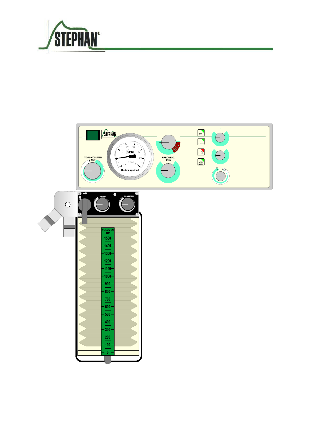
General description
The respirator ABV-A has to be supplied with compressed air as propellant gas with a
pressure of 3 - 5 bar (1). The various respiration parameters can be adjusted at the respirator:
ATEMZEITVERHÄLTNIS
INS P .: EXS P.
RESPIRATOR
EIN / A US
5
MANUAL
EXPIRATION (mbar)
MANUELL
RESPIRATOR
max.
INS P IR ATIO N ( m b a r )
max.min.
mbar
1:4
2:1
1:3
1, 5 : 1
1:1
1:2
1:1,5
606
7
50
8
40
9
30
10
25
12
20
14
16
min.
3 2 4
MAX.DRUCK
mbar
60
10
55
15
20
50
IPPV
45
25
303540
MIN.DRUCK
mbar
25
20 10
15
SE N SIT IV ITÄ T
P mbar
5
2 min
7
6
- breathing/time ratio (2)
- frequency (3)
- Min. / Max. Pressure / Sensitivity(4)
- volume (5)
- PEEP (6)
- PLATEAU (7)
Page 5
ABV – A - U Service - Manual Page 5
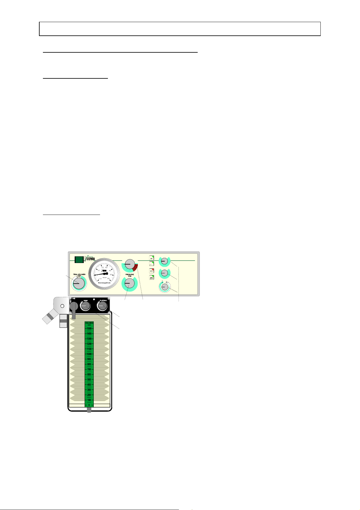
1.2 Respirator with patient unit
The respirator ABV-A is designed for controlled anaesthesia respiration with state-of-the-art
technology.
The respirator works in a pressure-gas driven, timed and volume-constant way, with the
possibility to limitate the inspiration pressure at the patient unit.
The patient unit is designed according to the "bag-in-bottle-principle", thus achieving a
separation of breathing gas and control gas. In addition, the patient unit serves as reservoir.
ATEMZEITVERHÄLTNIS
1
RESPIRA TOR
EIN / A U S
2
MANUAL
EXPIRATION (mbar)
MANUELL
RESPIRATOR
max.
INS PIR AT IO N (m b ar)
max.min.
mbar
min.
INSP.: EXSP.
1:4
2:1
1:3
1, 5 : 1
1:2
1:1
1:1,5
606
7
50
8
40
9
30
10
25
12
20
14
16
3 4 8
MAX.DRUCK
mbar
60
10
55
15
20
50
IPPV
45
25
303540
MIN.DRUCK
mbar
25
20 10
15
SENSITIVITÄT
P mbar
5
2 min
On the upper left side of the
6
respirator You find the ON/OFFswitch (1).
7
Directly below You find the
12
flow-control valve (2), where the
volume flowing to the patient's
lungs during inspiration can be
dosified.
5
The number of respiration cycles
can be varied from 6 to 60
breaths per minute at the
11
potentiometer "frequency"(3),
while the ratio of inspiration and
10
9
expiration can be preselected
from 1 : 4 to 2 : 1 with the switch
"breathing/time ratio"(4).
An excess-pressure proof
respiration manometer (5)
indicates the pressure in the
system within a range from -10 -
60 millibar. The patient pressure
can be controlled by setting of pressure alarm limits . Max.-pressure (6) and min.- pressure
(7) can be varied with potentiometers. In the case of exceeding the alarmlimits an optical
and visual (8) alarm is released.
In the event of a power outage, an acoustic signal sets off a warning for at least 30 sec. With
the change lever (9) of the patient unit, either respirator respiration or manual respiration can
be selected.
The PEEP-valve (10) serves to increase the pressure at the end of expiration to a maximum of
10 millibar. With the use of the plateau valve (11), You achieve a respiration with a constant
upper pressure limited to a maximum of 60 millibar.
Only ABV-U
The respirator ABV-U can support spontaneouse ventilation of a patient. For that reasons is
an additional membran key („assist.-control“) on the frontplate. The trigger sensitivity can be
adjusted with the potentiometer „Sensitivity“ (12).
Page 6

ABV – A - U Service - Manual Page 6
1.3 Adjustment of parameters at the respirator
1.3.1 Change of inspiration flow at the flow-control valve
In principle, it is possible to vary the inspiration flow at the flow-control valve in order to
reach a tidal volume of 0 - 1500 ml. In relation with the plateau pressure however, certain
respiration curves can be generated.
1.3.2 Frequency adjustment
The frequency (breaths per minute) can be adjusted for values between 6 and 60 breaths per
minute.
When adjusting the frequency, take into account, that with an increased frequency the breath
minute-volume remains constant, but that the tidal volume will be reduced.
1.3.3 Breathing/time ratio (inspiration/expiration)
The breathing/time ratio, the ratio of inspiration and expiration, can be preselected from
1 : 4 to 2 : 1 as the case might require, without influencing the respiration frequency.
1.3.4 Pressure monitor
The pressure monitor is an electronic module separated in two pressure-measurement ranges,
for the continuous control of the pressure the patient is subject to. The patientpressure is also
shown on the pressuregauge in the frontpanel of the ventilator.
Maximum pressure
The pressure-measurement range for the maximum pressure has a potentiometer which is to
be used to smoothly adjust the upper respiration-pressure limit for values between 6 and 60
millibar.
In the event, that the pressure for the patient exceeds the adjusted maximum pressure, the
pressure monitor sets off an optical and acoustic alarm until this pressure is no longer
exceeded.
Minimum pressure- or disconnection unit
The pressure-measurement range for the minimum pressure has a potentiometer, which is to
be used to smoothly adjust the minimum respiration-pressure limit-value for values between 5
and 25 millibar.
During one respiration cycle, the adjusted minimum-pressure limit-value has to be exceeded
once and fallen short of once, if this is not the case, an optical and acoustic alarm is set off.
Flashing red: minimum-limit pressure-value permanently exceeded (Stenosis or PEEP to
high), or value permanently not reached (disconnection).
In the event of an existing disconnection inside the system followed by a considerable
pressure drop, the disconnection warning is set off with a delay of 15 seconds.
Page 7

ABV – A - U Service - Manual Page 7
By pressing the STAND-BY foil button of the pressure monitor, the acoustic alarm can be
suppressed for 2 minutes.
The pressure monitor is to be set in operation with the operating switch of the respirator.
In case of an artificial respiration without the respirator, the pressure monitor is not working.
1.3.5 Control limit-value IPPB
As an option, with this respirator model a pressure-controlled respiration (IPPB) can be
carried out. For this kind of artificial respiration, expiration is induced when a preselected
maximum pressure is reached.
For this purpose, the excess-pressure limit value of the integrated pressure monitor serves as
pressure control.
The next inspiration cycle then will be set off by the time determined by the frequency.
Respirator "ABV-U"
In order to be able to work more successful in cases where the spontaneous respiration of the
patient has not yet failed completely or is showing signs of coming back, we offer a "ABV-U"
put-in respirator with integrated pressure monitor for assisted/controlled or pressurecontrolled respiration.
Caused by the inspiration efforts of the patient, a below atmospheric pressure is generated
inside the system, causing the respirator to carry out an additional and completely controlled
respiration lift in accordance with the preselected respiration parameters.
In the event, that the spontaneous respiration of the patient ceases completely, the respiration
frequency will be reduced to the preselected values and controlled respiration will be
continued automatically.
The suction, that has to be generated by the patient to trigger respiration in this mode, can be
varied with a sensitivity of 0.2 - 2 millibar of pressure difference at the adjusting knob for
sensitivity.
In the event, that the respirator is operated with a positive pressure at the end of expiration,
the trigger level is adapted to this value automatically.
Page 8

ABV – A - U Service - Manual Page 8
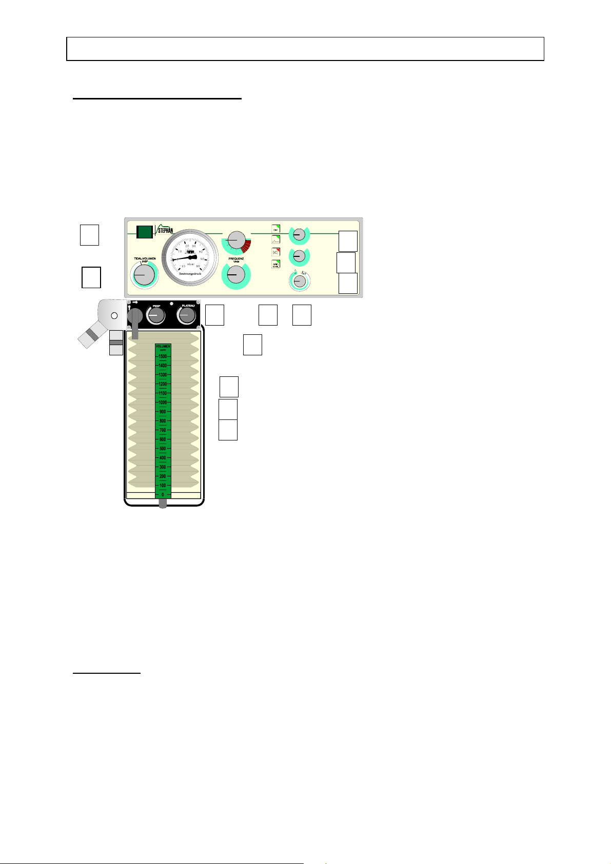
1.4 Patient component ABV-A
1.4.1 PEEP-adjustment
The so-called "positive end expiratory pressure" is to be adjusted with the left control of the
patient unit.
The reason for this increase of the pressure curve during expiration is to prevent the collapse
of alveoli, or even to inflate collapsed alveoli again in order to make their participation in the
gas exchange possible.
This PEEP is smoothly adjustable from 0 to 10 millibar, existing however a certain
dependence from the fresh-gas flow, which has to be taken into account for the adjustment.
1.4.2 PLATEAU adjustment
The maximum inspiration pressure is to be adjusted at the right control of the patient unit.
The purpose of this so-called plateau is to keep the breathed gas inside the lungs for a short
moment and at a constant pressure, in order to improve the alveolar gas exchange.
In addition, the plateau can be used as upper pressure-limit value or as a security device
against excess pressure.
The plateau value can be varied within a range from 10 to 60 millibar.
The plateau is only to be regarded as a pressure limitation and is not meant to be regarded as
part of a pressure-controlled respirator.
1.4.3 Change lever Respirator / manual
If a electrical power failure occurs , you can switch over to manual ventilation by moving the
handle at the left side of the patient-unit from „Respirator“ to „manual“. A rebreathing-bag
has to be connected at the outlet „Handbeatmung / manual“ of the patient-unit and the excessvalve at the circle-system has to be adjusted to the max. patient-pressure.
1.4.4 Ejektor / GAS EVAC
To evacuate the excess gas a tube can be connected at the outlet GAS EVAC .The connector
is a Iso-cone of 30 mm.
1.5 Patient unit for paediatric respiration
In order to allow the use of the anaesthesia apparatus for paediatric respiration without having
to carry out greater modifications, we designed a special plexiglass dome with an inner tube.
A rubber bellows developed for the artificial respiration of children is to be introduced in this
inner tube.
This plexiglass dome with rubber bellows can be exchanged easily in next to no time. The
volume of this paediatric system can be varied from 0 to 400 ml.
Page 9

ABV – A - U Service - Manual Page 9
l
2. Function scheme
2.1 Technical course of events during inspiration
Test
lung
Excess-valve
for manua
Funktionschem a
Inspiration
Drivinggas
Air / (O
Exspiration
Valve
)
2
Inspiration
Valve
Press.
Gauge
Volume-valve
Gas Evac
P
P
CPU
Power
supply
Solenoid
Valve
Drivinggas
exhaust
PEEP
Valve
012mbar
PLATEAU
Ventilator
/ manual
Valve
15 65 mbar
Freshgas
At the beginning of inspiration, the solenoid valve of the respirator opens and remains open
during the period of time, that has been preselected for inspiration.
In the patient unit , the system is made tight with respect to the ejector and the surrounding
area by pressure applied to the PEEP-diaphragm, and the pressure is limited at the plateau
valve.
The pressure built-up in the plexiglass dome presses the fresh gas and the breathing gas for
the patient out of the bellows, thus bringing it to the patient.
The respiration pressure, that is building up, can be read simultaneously from the manometers
of the respirator and the circular system .
In the event, that the respiration pressure reaches the adjusted plateau pressure limit before
the time for inspiration is over, the plateau valve opens and propellant gas is emitted to the
surrounding area. A continuous control of pressures during inspiration is guaranteed by the
pressure monitor . In the event of exceeding a preselected pressure limit, an optical and
acoustic alarm is set off .
Page 10

ABV – A - U Service - Manual Page 10
2.2 Technical course of events during expiration
Expiration
Alimentation
When the selected inspiration time is over, the solenoid valve cuts the gas supply and opens
the system towards the surrounding area.
The excess pressure in the lungs of the patient closes the inspiration valve and opens the
expiration valve . The patient breathes through the expiration valve into the inflating bellows,
which is pressed down.
The superfluous consumed breathing air is conducted through the diaphragm of the PEEPvalve to the anaesthesia gas extraction. During this process, the diaphragm keeps up as much
pressure in the system, as is determined by the adjusted PEEP-value .
The reduction of the respiration pressure and the remaining pressure at the end of expiration
are displayed by the manometer of the circular system and that of the respirator .
By switching to hand/respirator , the manual respiration bag is directly connected with the
system, thus allowing manual artificial respiration.
Note : If switched over to manual respiration , the PLATEAU valve is out of function
and the excess valve has to be opened to control the max. pressure of the patient .
Page 11

ABV – A - U Service - Manual Page 11
3. Servicing of basic apparatus
Transform Fuse 2 x 1,25 Buzzer
Outle
driving
gas
Solenoi
valv
ON /
Switc
Potential Analog Power
I
Control
Volume Gaug Min.- Max.- s.
3.1 Electronic
The electronic of the ABV-A is according to the different tasks divided in 4 printed circuits ,
connected via a SPI - Bus or wire.
The circuits are :
1. Users circuit - Frequency adjustment
- RATIO Adjustment
- Min. / Max. - Pres.limits
- switches for CMV / IPPV , audible alarm mute
- visual Alarms
2. Analogue circuit
- valve supporting IC`s
3. CPU
- control display
- watch dog
4. Power supply - central-connecting of all wires
- current and voltage supply
The electronics of the microprocessor-controlled respirator require no servicing. The control
system runs through test programs at each putting into operation, which activate visual and
audible alarm in case of malfunction.
In semi-annual cycles the apparatus has to undergo the following servicing, inspections and
adjustments.
- steering and controlling of all functions
- converting of analog signals
Page 12

ABV – A - U Service - Manual Page 12
3.2 Pneumatic
Volume valve
Check volume valve for leakage. If leakage occurs at the spindle change the inner O - rings
( 4 x 1,5 mm ). Lubricate eventually using silicone grease .
The volume valve is adjusted so , that in the closed position a minimal volume ( max. 100 ml
) is given to the system to avoid incorrect adjustments.
Solenoid valve
Check solenoid valve for leakage while the volume valve is complete open and the ventilator
is switched off . At the outlet of the solenoid valve should be no gas flow. If a leakage occurs
, change solenoid valve.
Manometer
Check of respiratory pressure manometer for
correct zero position (correction by means of
a screwdriver, through the setting aperture in
the Plexiglas cover).
Since a mechanic capsule-spring-manometer
is used for gauging pressure, it must be
checked whether the mechanic dial train is
still working faultlessly. Otherwise the
respiratory pressure manometer must be
exchanged.
Patient unit connector
Check the O - Rings of the connection block for damages. Change O - Rings ( 10 x 2,5 mm )
if necessary . Lubricate eventually using silicone grease .
4. Sight check
Inspection of apparatus for visible external damages.
5. Performance check
5.1 Self-test of respirator
Note :
( Magill ,Jackson-Rees , etc.) and a gas-mixing unit supporting the system with a
freshgas - flow !
All following tests require the presence of a circle-system or narcotic-system
Page 13

ABV – A - U Service - Manual Page 13
On the upper left side of the respirator You find the ON/OFF-switch .
Depressing it starts a test program with an automatic self-test, which checks all keys, switches
and potentiometers. Furthermore the functioning of magnetic valve,pressure sensors and parts
of the hard- and software and digital switching circuits is tested. If a fault is detected the
respirator gives off an audible signal and switches itself off.
If a defect occurs, the display on the electronic block inside of the ventilator gives an
information about the type of the defect.
To look onto the display you have to remove the cover.
5.2 Errorcodes / Operation - Display
The display shows the condition of the solenoid valve.
„ I “ = Inspiration
„ E „ = Expiration
Errorcodes
Different errorcodes can be generated on the display.
Reading „ 0 “ - Fault in the circuit of the potentiometers. Check connecting wires or poti .
Reading „ 1 “ - Fault in the circuit of the pressure sensors. Check tubes for leakage.
Reading „ 2 “ - Fault in the circuit of the solenoid valve . Check connecting wires .
Reading „ 3 “ - Power failure
5.3. Operating mode CMV
Check of the set respiratory frequency
The respirator is adjusted so, that no pressure alarms or stenosis alarms are released.
-1
Respiratory frequency ( BPM ) is set at 6 min
and the respiratory time ratio I : E at 1 : 4. The
values for inspiration time and expiration time must then be measured by hand (stopwatch).
Frequency must be calculated accordingly. The calculated frequency must correspond with
the set frequency. If this is not the case an error exists in the software of the respirator. In this
case the manufacturer must be notified. All measured and calculated values must be
registered in the test records.
Respiratory frequency = 60 sec / (inspiration time + expiration time)
allowed Tolerance = +/- 5 % or 3 BPM ( what ever is bigger )
From the measured values for inspiration and expiration the set value of respiratory frequency
must result by calculation.
Furthermore the set respiratory time ratio must result by calculation from the measured values
for inspiration and expiration.
Respiratory time ratio = I : E = Insp.time / expir.time
allowed Tolerance = +/- 5 %
Page 14

ABV – A - U Service - Manual Page 14
The calculatory check of respiratory frequency and respiratory time ratio must be repeated, in
the same mode as described above, with the following settings:
Respiratory frequency = 12 l/min, I : E = 1 : 2
Respiratory frequency = 30 l/min, I : E = 1 : 1
5.4 Operating mode IPPV
With IPPV-ventilation it must be checked, whether a change-over from inspiration to
expiration takes place, when the set maximum pressure is reached.
Set respiratory frequency at 6 l/min and the respiratory time ratio I : E at 1 : 4.
By means of the plateau valve on the patient component, plateau pressure is set higher than
the maximum pressure value. When the respiratory pressure reaches the set maximum
pressure value during inspiration time, the change-over to expiration must take place
prematurely.
Note : In the IPPV - mode the time for inspiration can be shorter than adjusted because
of the change-over to expiration when the set pressure is reached . Otherwise
the time for expiration is as adjusted . The result is a increasing of the respiratory
frequency taking into consideration the lost inspiratory time after change-over to
expiration .
5.5 Pressure alarms
The respirator ABV-A is provided with devices for recognition of disconnection and stenosis.
The respiratory pressure is picked up in the expiration branch on the patient component. For
this purpose a pressure-measuring tube in the respirator is connected with the patient
component ABV-A via the gas connection nipple. This pressure measuring tube is conducted
directly to the manometer. By the manometer the pressure measuring tube is connected with
the two pressure sensors on the board.One sensor is only used to control the signal of the
other sensor.With the help of the electronics of the board the analogous pressure signal is
converted into digital signals and processed.
The software installed on the board of the processor evaluates these signals and checks them
for validity and appropriate limit values.
The pressure alarm limit is set by means of the potentiometer for „ Max. Pressure“. If the
measured pressure exceeds the set maximum pressure limit, an audible and visual alarm is
immediately released.
The disconnection alarm limit is set by means of the potentiometer for „Min. Pressure“. If the
measured pressure does not exceed the set minimum pressure limit, an audible and visual
alarm is immediately released.
To test the correct performance of the pressure alarm the Y-piece must be connected to a test
lung with the respirator switched on. Maximum pressure is set at 40 mbar, minimum pressure
at 10 mbar and plateau pressure at 50 mbar (PEEP = 5 mbar). If the set max imum pressure
limit is exceeded, an audible and visual alarm must be activated immediately and continue for
duration of exceeding. When the measured pressure falls below the set pressure audible and
visual alarm are cancelled.
Page 15

ABV – A - U Service - Manual Page 15
Disconnectionalarm
To test the correct performance of the disconnection alarm the corrugated tube of the
narcotic-system has to be pulled off from the patient component with respirator switched on,
so no more built-up of pressure can take place. Maximum pressure is set at 50 mbar,
minimum pressure at 10 mbar and plateau pressure at 40 mbar (PEEP = 5 mbar). A
disconnection alarm is released after a delay time (length of delay time depends on the set
expiration time plus 15 sec.
-1
e.g. BPM = 15 min
, I : E - Ratio = 1:1 ,
=> T
=> T
= 2 sec.
exp.
= 2s + 15s = 17s ).
delay
After slipping the corrugated tube back onto the patient component and according built-up of
pressure in the patient tube system, the alarm must be automatically cancelled.
Stenosis alarm
A stenosis alarm is released, if after a delay time (length of delay time depends on the set
expiration time plus 15 s. s.ab.) the respiratory pressure does not fall below the set minimum
pressure limit.
To test the correct performance of the alarm, the PEEP-value, with the respirator switched on
and the complete patient tube system connected, must be set higher than the minimum
pressure-limit , so that the measured pressure does not fall below the minimum pressure-limit.
After the delay time an audible and visual alarm is released. When the PEEP-value is reduced,
so that the minimum
pressure limit is remaining under again, the stenosis alarm ceases.
Two-minute stand-by (muting of audible alarm)
Proceed as for disconnection alarm. Wait until disconnection alarm activates, depress standby key and measure duration of muting of audible alarm.
Failure-of-current-alarm
With the respirator switched on, pull mains plug from socket and so simulate a failure of
current supply. Now an audible alarm must be activated.
6. Check of electrical safety (STK)
The three Parameter, resistance of protective conductor, resistance of insulation,
compensating apparatus leakage current must be measured, using the test kit.
The maximum limit values are determined as follows:
Resistance of protective conductor < = 0,2
Resistance of insulation > = 70 M
Compensating apparatus leakage current < = 1 mA
Ω
Ω
Page 16

ABV – A - U Service - Manual Page 16
7. Patient unit ABV-A
With every semi-annual check, the O-rings of the gas-connection nipples on the connecting
unit must be exchanged.
Furthermore the front panel of the patient component should be loosened and removed semiannually. All removable accessible parts should be cleaned with alcohol.
We especially point out, that the inner part require intensive control and ,if necessary
,cleaning. In case of considerable wear (mechanical actuation) the PEEP-valve-disc must be
exchanged.
The valve spindles must be tested for smooth working (lubricate eventually using silicone
grease). The O-rings of the valve spindles (O-ring 12 x 1) must be checked for intactness and
must be exchanged if necessary.
If this has been completed, put the front panel back on. In doing so, care has to be taken that
the springs are placed correctly in the fairleads of the spring spindles.
Performance of the patient component must be tested prior to the final tightening of the front
panel, an eventual slight adjustment of the front panel on the basic body may be necessary
(align with the outer edge).
Finally the patient component attached to the respirator is operated with a flow of
approximately 5 litres and with a narcotic- system with a testlung. Hereby the control knobs
have to be checked and eventually readjusted.
The plateau-control knob has to be installed so that at its right-hand stop a pressure of 65
mbar is just reached.
The PEEP-control knob has to be installed so, that at its right-hand stop a pressure of 12 mbar
is reached.
MANUELL
MANUAL
RESPIRATOR
EXPIRATIO N (mbar)
max.
IN S P IR A T IO N ( m b ar )
max.min.
mbar
min.
Page 17

ABV – A - U Service - Manual Page 17
8. Cleaning & Sterilisation
8.1 Ventilator ABV-A
The ventilator can be cleaned using normal cold sterilisation solutions or soapy water.
Don`t use volatile solvents.
8.2 Patient unit
Disassembly
M ANUAL
EXPIRATION (m bar)
MANUELL
RESPIRATO R
max.
IN S P IR A T IO N (m b a r )
max.
min. min.
mbar
- Loosen knurled screw
- Pull off patient unit
- Pull clamp climp forward
- Take off plexiglass cylinder
- Pull off bellows and O-ring
All parts, except of the base part of the patient unit, should undergo a precleaning or a
predesinfection, which is to be carried out as follows:
Put all parts (including rubber parts) in a disinfectant solution.
After the exposure time prescribed by the disinfectant manufacturer, thoroughly rinse all parts
with water.
In order to avoid corrosion and the propagation of germs, it is recommendable to dry the
parts.
Do not clean rubber parts with hard or sharp objects, in order to avoid damages.
Page 18

ABV – A - U Service - Manual Page 18
Sterilisation
The rubber bellows (4) and the O-ring (3) have to undergo a superheated-steam sterilisation at
°C (glove program).
121
The base part of the patient unit (2) and the clamp climp (6) have to be sterilised in the
autoclave at 134
°C.
The base part of the patient unit must not be cleaned with compressed air.
Assembly
Now that the parts are perfectly hygienic, reverse order of disassembly for assembly.
Before putting on the patient unit, lubricate the thread of the knurled screw (1) with a bit of
grease.
Page 19

ABV – A - U Service - Manual Page 19
9. Error-flow diagram
9.1 Respirator
Fault Possible cause Remedy
respirator without
respiration pressure
"PEEP" to high - PEEP-diaphragm sticks
tidal volume of patient
part differs extremely
from that of the
volumeter
difference 300 ml - untightness in the circular
- volume valve closed -open volume valve
- clean PEEP-diaphragm
(caused by inadequate
sterilisation, for example)
-inspiration valve or
expiration valve installed
incorrectly (for example
missing valve plate, result:
inconstant volume)
system
- excess valve not in
position "CL"
control inspiration and
expiration valve
- check for tightness
- switch excess valve to
position "CL"
9.2 Pressure monitor
Fault Possible cause Remedy
minimum-pressure alarm
is set off
excess-pressure alarm is
set off
- preselected minimum
pressure limit value to small
- PEEP above minimum
pressure limit value
- disconnection at the
anaesthesia apparatus
(circular system)
- changes of with respect to
the patient (compliance,
resistance, TUBUSLAGE)
- pressure limit below
PLATEAU-pressure
- upper pressure limit value
below top-pressure of
respiration
- change of TUBUSLAGE
change with respect to the
patient (stenosis)
- select minimum pressure
limit value of more than 10
millibar
- reduce PEEP or increase
minimum pressure limit
value
- search disconnection and
re-establish connection
reduce PLATEAU-pressure
or increase pressure limit
reduce respiration pressure
or increase upper pressure
limit
Page 20

ABV – A - U Service - Manual Page 20
10. Specification sheet
10.1 Ventilator module ABV - A
Measurements:
Width: 530 mm
Height: 120 mm
Front-to-back size: 280 mm
Weight: 12 kg
Fuses: 2 x 1.25 A trg.
3 x 20 mm
Line voltage: 230 V / 50 c.p.s.
Absorption of power: 18 VA
Respiration frequency: 6 - 60 breaths per minute
Breathing/time ratio: insp. : exp. from 1 : 4 to 2 : 1
Pneumatometer: -10 - 60 millibar
excess-pressure proof to 600 millibar
Power outage alarm: acoustic for at least 30 sec.
Pressure monitor
Measuring range: 0 - 60 millibar
Measuring accuracy: +/- 1 %
Measuring principle: piezoresistent pressure pick-up
Excess pressure alarm
limit value adjustable: from 5 - 60 millibar
Minimum pressure alarm
limit value adjustable: from 5 - 25 millibar
Alarm for
- excess pressure: LED, red , visual
- minimum pressure: LED, flashing red , visual
- acoustic alarm: electronic, can be suppressed for 2 minutes
Page 21

ABV – A - U Service - Manual Page 21
10.2 Patient component
Tidal-Volume: 0 - 1500 ml adult version of patient unit
0 - 400 ml paediatric version of patient unit
PEEP-valve: 0 - 10 millibar
PLATEAU-valve: 10 - 60 millibar
(upper pressure limitation)
Page 22

ABV – A - U Service - Manual Page 22
11. Spare - Part - List
Pos Articleno. Description
115 61 000 Ventilator ABV - A
1 905 32 010 Cover V2A
2 923 60 002 Manometer -10 - 60 mbar
3 810 60 317 Trafo BV 4374
4 105 60 024 Buzzer
5 804 60 004 Fuse 1,25AT
6 804 60 001 Fuse holder
7 804 60 002 Fuse assembly
8 801 60 040 Potential earth connector
9 105 61 013 Solenoid valve
10 105 31 001 Volume valve
11 950 60 006 O - ring 10 x 2,5 mm
12 926 60 004 Turning knob 20 mm
13 926 60 006 Cover for knob 20mm
14 926 60 005 Arrow disk for knob 20 mm
15 926 60 001 Turningknob 28 mm
16 926 60 003 Cover for knob 28 mm
17 926 60 002 Arrow disk for knob 28 mm
18 810 60 530 On / Off switch
19 810 60 537 Lamp for switch
Transformer Fuse 2 x 1,25 AT CPU Buzzer
Outlet
driving -
gas
Solenoid
valve
ON / OFF
Switch
Volume valve Gauge BPM Ratio Min.-Press. Max.- Press.
Potential Earth Analog curcuit Power supply
I
Control Display
Page 23

ABV – A - U Service - Manual Page 23
153 61 000 Patient component ABV-A (Adult)
1 153 61 016 knurled screw
2 153 40 024 base part
3 950 60 022 O-ring , 105 x 3,5 mm
4 153 61 009 rubber bellows
5 153 61 014 plexiglas dome
6 153 40 032 fixing bracket
7 926 60 007 turning knob , black
8 153 42 022 switch lever
9 153 71 023 front plate , complete with accessoires
7 1 2
9
8
3
4
6
5
12. Maintenance
In accordance with the "Regulation of Security of Medical and Technical Equipment"
(MedGV), medical/technical equipment has to undergo regular inspections.
Such an inspection has to be carried out exclusively by authorised persons (service personnel)
of the supplier of the equipment.
Regular maintenance and inspection every six months.
You achieve the best guarantee by concluding a maintenance agreement, which includes
regular inspections every six months with automatic replacement of parts with a risk of wear.
In the event, that maintenance is carried out by unauthorised personnel without the necessary
expertise, the liability of the manufacturer for the secure function of the equipment ceases
immediately.
 Loading...