

Page 1
Plug-in Reference
Page 2

Cristina Bachmann, Heiko Bischoff, Lillie Harris, Christina Kaboth, Insa Mingers, Matthias Obrecht, Sabine Pfeifer,
Benjamin Schütte, Marita Sladek
This PDF provides improved access for vision-impaired users. Please note that due to the complexity and number
of images in this document, it is not possible to include text descriptions of images.
The information in this document is subject to change without notice and does not represent a commitment on
the part of Steinberg Media Technologies GmbH. The software described by this document is subject to a License
Agreement and may not be copied to other media except as specically allowed in the License Agreement. No
part of this publication may be copied, reproduced, or otherwise transmitted or recorded, for any purpose,
without prior written permission by Steinberg Media Technologies GmbH. Registered licensees of the product
described herein may print one copy of this document for their personal use.
All product and company names are ™ or ® trademarks of their respective owners. For more information, please
visit www.steinberg.net/trademarks.
© Steinberg Media Technologies GmbH, 2019.
All rights reserved.
WaveLab Pro_10.0.0_en-US_2019-10-15
Page 3

Table of Contents
4 WaveLab-specic Plug-ins
4 Resampler
4 Ducker
5 Leveler
6 Leveler Multi
6 MasterRig
23 Peak Master
24 RestoreRig
28 Silence
28 Stereo Expander
29 Steinberg VST 3 Plug-ins
29 AutoPan
30 Brickwall Limiter
31 Channel Extractor
31 Chorus
32 Compressor
34 CurveEQ
34 DeEsser
36 Distortion
37 DualFilter
37 EnvelopeShaper
38 Expander
40 Frequency
43 Gate
45 GEQ-10/GEQ-30
46 Limiter
47 L/R to M/S, M/S to L/R
47 Magneto II
48 Maximizer
49 Mix6to2
50 Mix8to2
51 MonoDelay
51 MonoToStereo
52 MultibandCompressor
54 MultibandEnvelopeShaper
56 MultibandExpander
58 Octaver
58 PingPongDelay
59 PostFilter
61 REVelation
63 RoomWorks
66 RoomWorks SE
66 StereoDelay
67 StereoEnhancer
68 Stereo Tools
69 StudioChorus
70 StudioEQ
72 TestGenerator
73 Tube Compressor
74 VintageCompressor
75 VSTDynamics
79 Legacy Plug-ins
80 Dithering Plug-ins
80 Internal Dithering
80 MBIT+™ Dithering
82 UV22HR
83 ASIO Plug-ins
83 External Gear
84 Audio Input
85 Batch Processing Plug-ins
85 Audio Analyzer
87 Audio Injector
87 Audio Mixer
88 DC Remover
88 Delay Next Process Activation
88 Fade In/Fade Out
89 Instructor
90 Level Normalizer
90 Loudness Meta Normalizer
91 Loudness Restorer
92 Meta Leveler
92 Resizer
92 Stereo to Mono
93 Trimmer
94 Index
3
Page 4
WaveLab-specic Plug-ins
WaveLab-specic plug-ins use the plug-in format of WaveLab, and cannot be used with other
applications.
● WaveLab-specic plug-ins can only be used in the Master Section and in batch processes.
WaveLab effects are also included as VST plug-ins, available as track or clip
● You can specify which plug-ins should be available on the Effects pane and the Final
●
Resampler
This plug-in is a professional sample rate converter providing exceptional transparency and
preservation of the frequency content. It is only available in the Master Section.
However, some
effects in audio montages.
Effects/Dithering pane of the Master Section by using the Plug-in Settings dialog.
When a multichannel conguration is used in the audio montage, only certain plug-ins can
be used as master effects. All channels in the Master Section are affected equally.
Ducker
NOTE
This plug-in is very CPU consuming, especially in high quality modes.
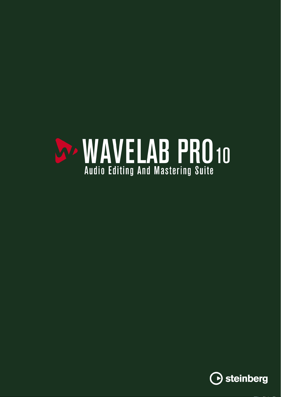
Output Sample Rate
Denes the output sample rate while the input sample rate is determined by the
sample rate of the active audio
Quality
Denes the quality of the algorithm that is used (Standard, High, Very High, Best).
In
Standard mode, the CPU load is much lower than in Best mode but the sound
quality of the resulting audio is also lower.
This plug-in lets you control (modulate) the volume of clips placed on a track with the signal of
one or more clips placed on the next adjacent track below it. The Ducker plug-in can only be
used as a clip effect in the audio montage.
It uses the Route to options that can be found on the Track menu. You can use mono or stereo
tracks for both the modulating and the upper track.
le or audio montage.
4
Page 5
WaveLab-specic Plug-ins
Leveler
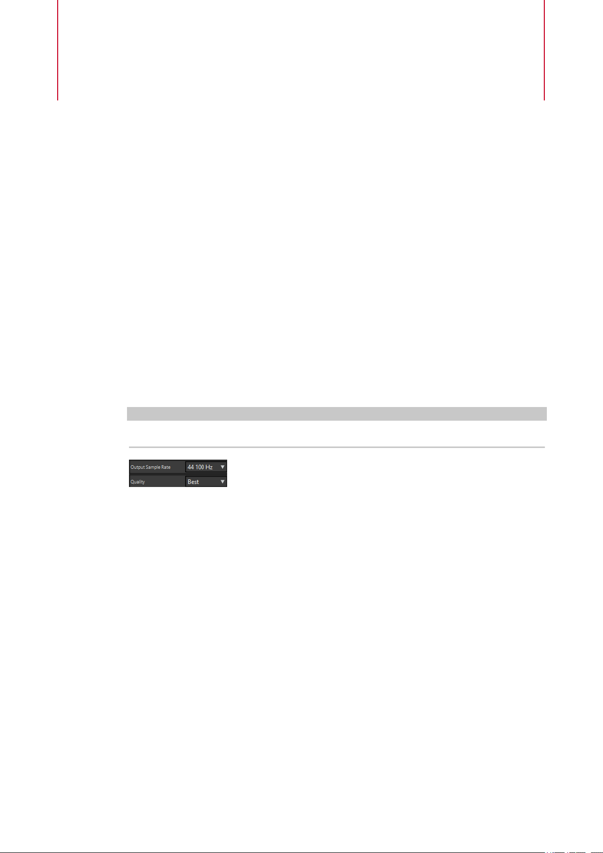
Threshold
Sets the loudness threshold that triggers the Ducker. Clips on the modulator track
with levels above the threshold will cause the level of a clip on the upper track to be
lowered.
Damping
Sets the amount of level reduction that is applied to the clip on the upper track.
Fall Time
Sets the time it takes for the level to change from 0 dB to the set damping level.
Leveler
Hold Time
When the modulating signal falls below the set threshold, this setting determines
how long the level will stay reduced before it starts rising to normal level again.
Rise Time
Sets the time after which the reduced level rises to the normal level when the
modulating signal falls below the set threshold (after the Hold Time).
Mix Mode
If this is activated, the Ducker outputs a mix of the two tracks. This is only useful if
the Route to Upper Track Only option has been activated for the modulating track.
Then this feature can be used for processing several clips through the same plug-in
chain if more plug-ins have been assigned after the Ducker on the upper track.
Note that the mixed output is controlled by the upper track. If this is not playing a
clip, both of the tracks will be silent.
This plug-in is useful for correcting an imbalance or adjusting levels between stereo channels, or
for mixing down to mono.
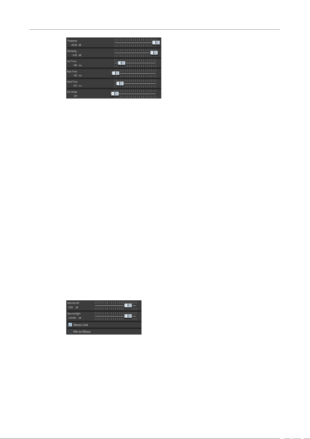
Volume Left/Volume Right (-48 dB to 12 dB)
Governs how much of the signal is included in the left and/or right channel of the
output bus.
Stereo Link
If this option is activated, Volume Right delivers the gain that is set for Volume Left.
5
Page 6
WaveLab-specic Plug-ins
Leveler Multi
Mix to Mono
If this option is activated, a mono mix of the stereo channels is delivered to the
output bus.
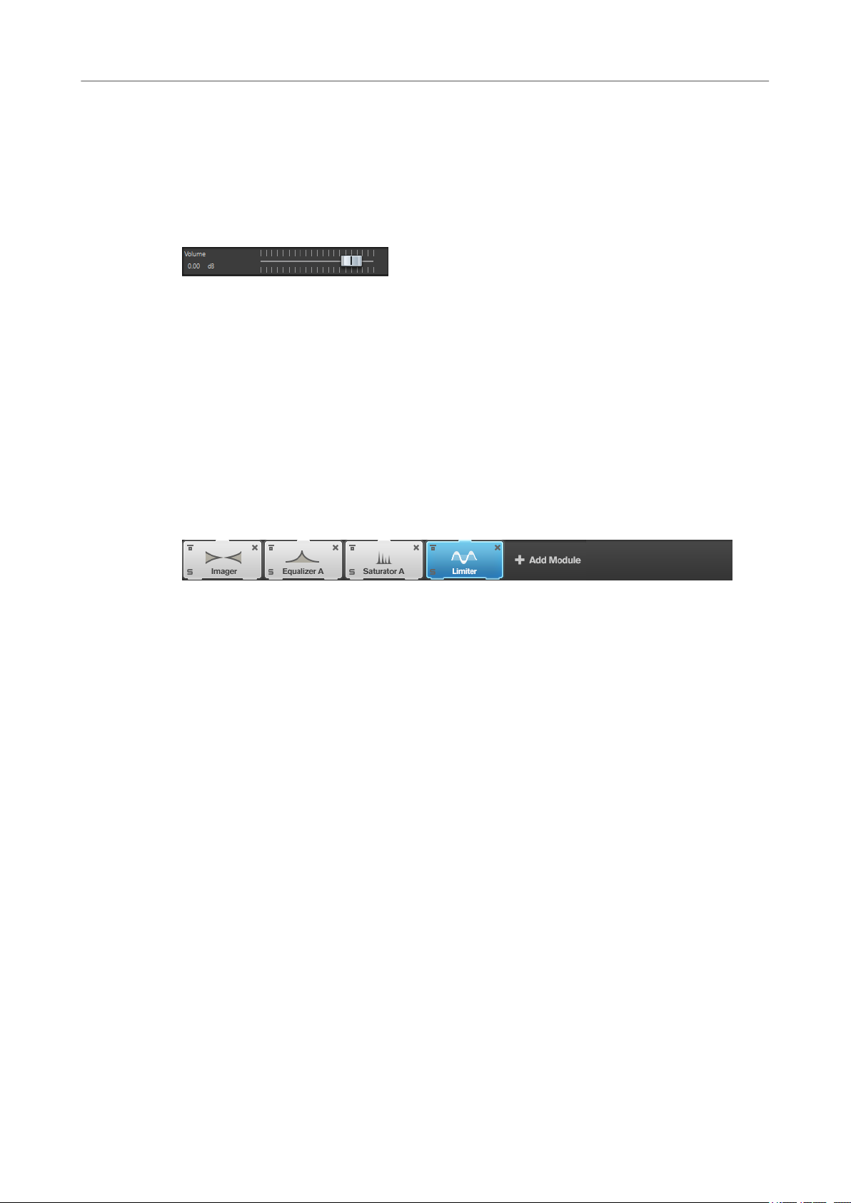
Leveler Multi
This plug-in takes multichannel input and applies a fader equally to all channels.
Volume (-48 dB to 12 dB)
Governs how much gain is applied to the signal before it is routed to the output bus.
MasterRig
MasterRig allows you to master audio material in an intuitive and creative way. It offers high-
class sound quality, accuracy, exibility, and control.
Main Layout
Module Chain
The module chain contains the mastering modules. You can add up to 8 modules.
The following settings are available for each module:
Bypass
Bypasses the module. This allows you to compare the sound of the unprocessed
signal to that of the processed signal.
Solo
Solos the module. Only one module can be soloed at a time.
Remove
Removes the module from the module chain.
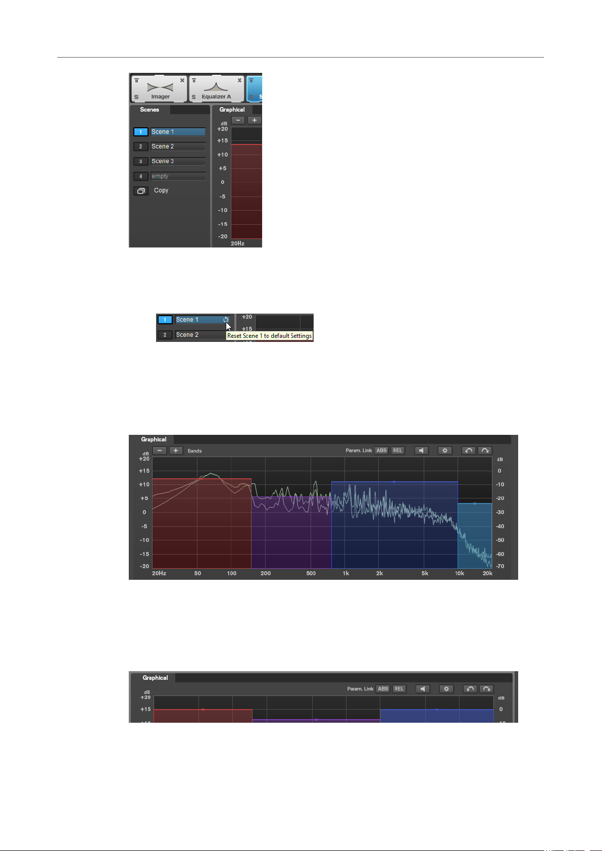
Scenes
You can save up to 4 MasterRig congurations as scenes. This allows you to compare different
parameter settings and module combinations.
6
Page 7
WaveLab-specic Plug-ins
MasterRig
● To copy the settings of a scene to another scene, click Copy Scene, and then click the
scene button of the scene where you want to paste the settings.
A copy of a scene is indicated by a (c) behind the scene name.
● To reset the settings of the selected scene, click Reset Scene.
● To rename a scene, double-click the scene name and type in another name.
Spectrum Display
The spectrum display in the upper half of the panel is where you set the width of the frequency
bands. The vertical value scale to the left shows the gain level of each frequency band. The
horizontal scale shows the frequency range.
● To dene the frequency range of the different frequency bands, use the handles at the
sides of each frequency band.
● To attenuate or boost the output level of each frequency band by ±15 dB, use the handles
on top of each frequency band.
Settings
7
Page 8
WaveLab-specic Plug-ins
MasterRig
Parameter Linking
Links the parameters of the same type in all bands in a module. This allows you to
edit parameter values of all bands in a module simultaneously. Two link modes are
available:
● If Absolute Mode is activated and you edit a parameter value in one band, the
● If Relative Mode is activated and you edit a parameter value in one band, the
Auto Listen for Filters
If this option is activated and you edit a parameter of a module, the corresponding
lter or band is soloed. This allows you to locate unwanted frequencies in your audio
and helps you to focus on a particular band or lter. Once you stop editing the
parameter,
Global Settings
Allows you to make global settings for MasterRig.
Undo/Redo
Undoes/Redoes the last operation. The undo/redo history is deleted when you select
another scene.
Absolute and Relative.
corresponding parameter values in the other bands are set to the same value.
corresponding parameter values in the other bands keep their relation.
Solo is deactivated.
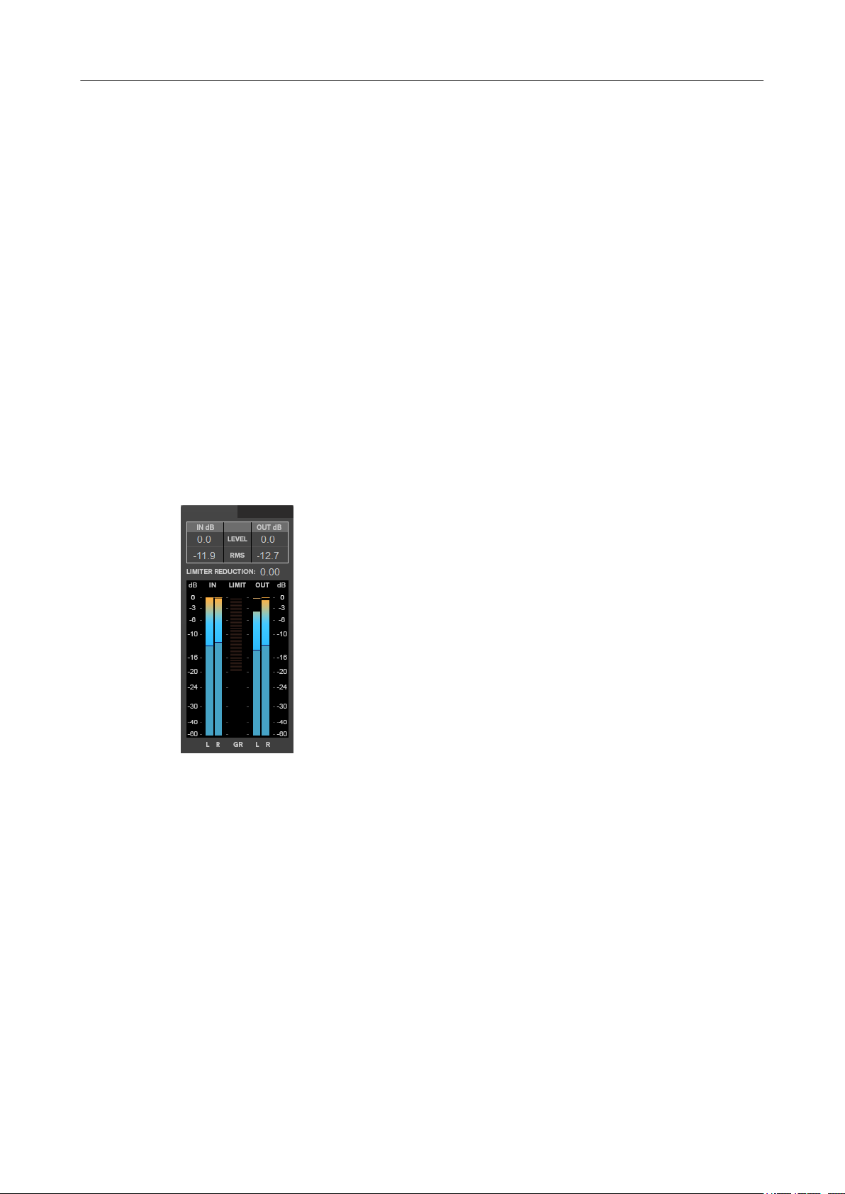
Input/Output Meter
The input/output meter provides a combined peak level, with peak-hold functionality and RMS
meter. Between the meters for input and output is the gain reduction meter for the Limiter.
The maximum values for input/output peak level, RMS, and gain reduction are displayed above
the meter display. To reset all maximum values, click any of the values.
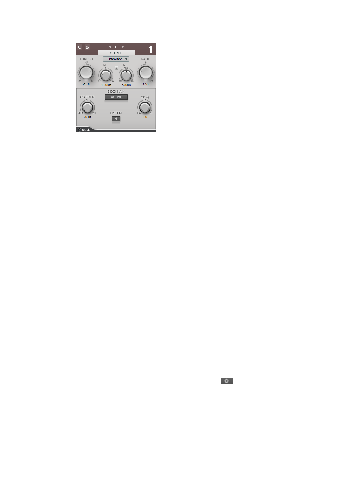
Side-Chain Settings
The Compressor module and the Dynamic EQ module support side-chain. You can set up the
side-chain routing for each band separately.
● To open the side-chain panel, click the SC button at the bottom left of each band section.
8
Page 9
WaveLab-specic Plug-ins
MasterRig
Active
Activates the internal side-chain lter. The input signal can then be shaped according
to the lter parameters.
SC FREQ
Sets the frequency of the side-chain lter.
Auto (Dynamic EQ only)
Deactivates the SC Frequency knob of the side-chain panel. Instead, the settings of
the Frequency knob are used.
Listen
SC Q
Modules
Modules allow you to create a mastering chain. Some modules can be used only once and some
in two instances in the module chain. You can rearrange modules in the module chain to change
the processing order.
● To add a module to the module chain, click Add Module in the modules section and click a
● To remove a module, click the corresponding Remove button.
● To bypass a module, click the corresponding Bypass button.
● To solo a module, click the corresponding Solo button.
● To change the order of the modules, drag a module to another position in the module
Global Settings
● To open the Global Settings, click Global Settings above the spectrum display.
Allows you to solo the side-chain lter.
Sets the resonance or width of the lter.
module.
chain.
Spectrum Display
Show Spectrum
Activates/Deactivates the spectrum display.
Smooth
Determines the reaction time of the spectrum display. Lower values result in faster
reaction times.
9
Page 10
WaveLab-specic Plug-ins
MasterRig
Peak Hold
Freezes the peak values of the spectrum display.
Slope
Tilts the spectrum display around the 1 kHz pivot.
Two Channels
If this option is activated, the spectrum of the left and right channels are displayed
separately.
EQ Curve
Show Curve
Shows/Hides the EQ curve in the spectrum display.
Filled
If this option is activated, the EQ curve is lled.
RMS
AES17 (+3 dB)
If this option is activated, the RMS value is raised by 3 dB to follow the AES17
standard.
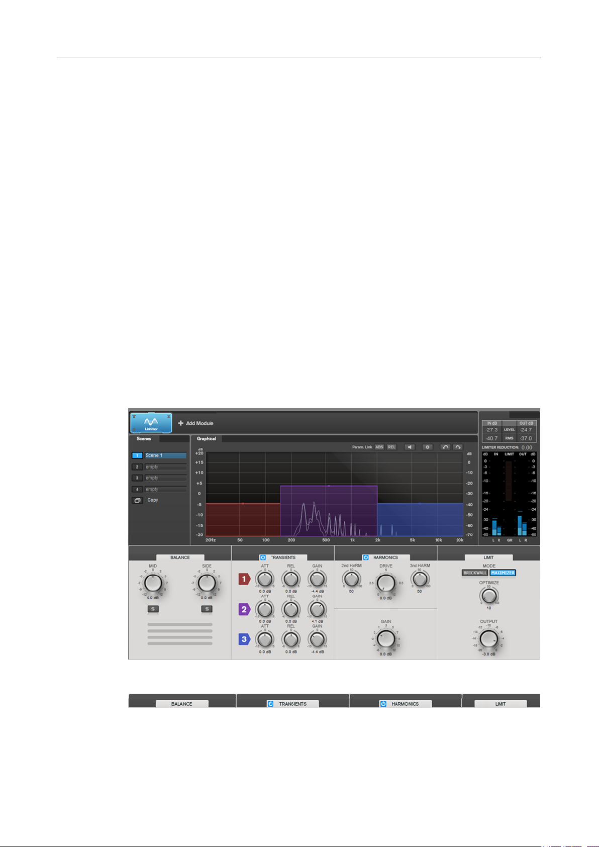
Limiter
The Limiter module makes sure that the output level never exceeds a set output level, to avoid
clipping in following devices.
Band Settings
On/Off
Activates/Deactivates the corresponding section.
10
Page 11
WaveLab-specic Plug-ins
MasterRig
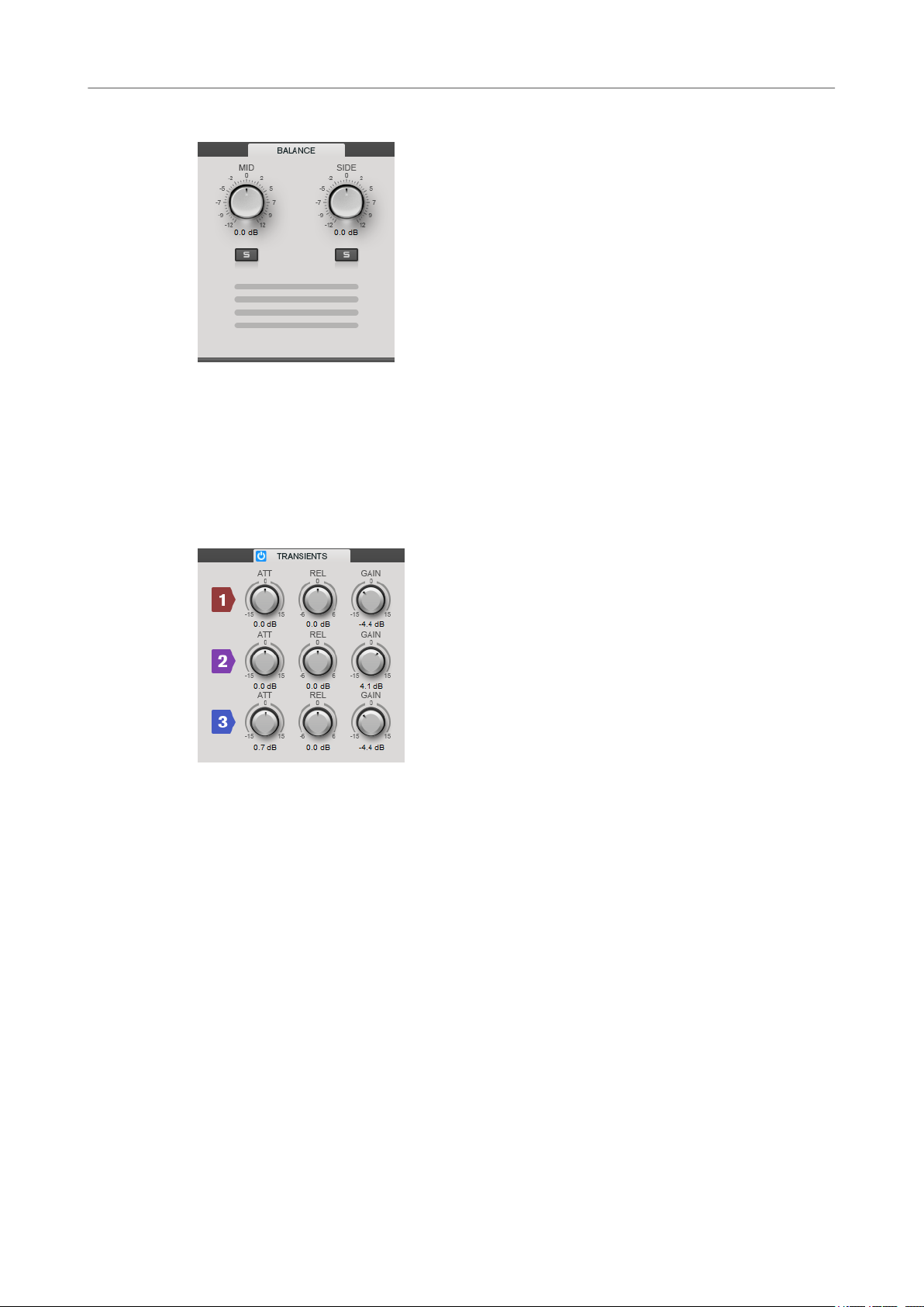
Balance
Mid/Side
Allow you to set the gain for the mid and side signal.
Solo Mid Signal/Solo Side Signal
Allow you to solo the mid or side signal.
Transients
If the Transients section is activated, you can set the following parameters:
ATT
Sets the gain of the attack phase of the signal for the corresponding band.
REL
Sets the gain of the release phase of the signal for the corresponding band.
Gain
Sets the output level for the corresponding band.
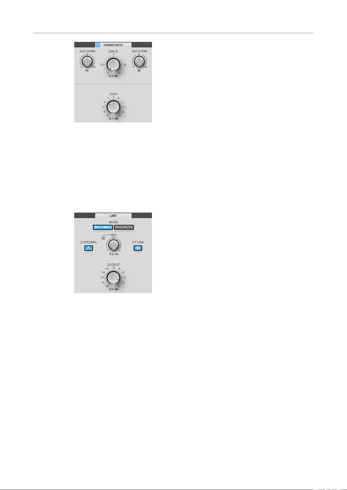
Harmonics
If the Harmonics section is activated, the Limiter module starts limiting the signal softly. At the
same time, harmonics are generated, adding a warm, tube-like characteristic to the audio
material.
11
Page 12
WaveLab-specic Plug-ins
MasterRig
2nd HARM/3rd HARM
Allow you to control the second and third harmonic independently.
Drive
Allows you to adjust the amount of gain boost for the signal to raise the amount of
soft-clipping.
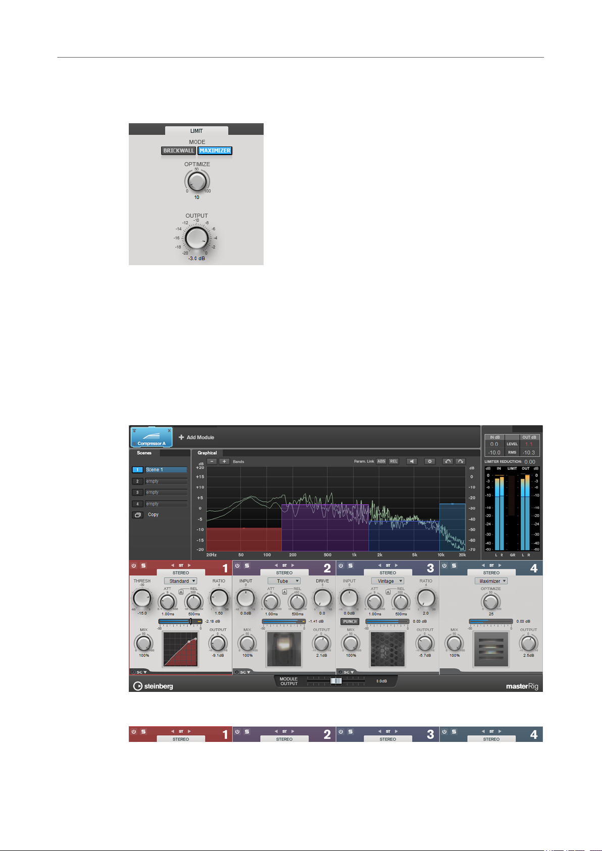
Brickwall
Due to its fast attack time, Brickwall Limiter can reduce even short audio level peaks without
creating audible artifacts. The limiting amount is displayed between the input and the output
meter.
Release
Sets the time after which the gain returns to the original level when the signal drops
below the threshold. If Auto Release is activated, the plug-in automatically nds the
best release setting for the audio material.
Oversample
If this option is activated, Brickwall Limiter detects and limits signal levels between
two samples to prevent distortion when converting digital signals into analog
signals.
Stereo Link
If this option is activated, Brickwall Limiter uses the channel with the highest level
to analyze the input signal. If the button is deactivated, each channel is analyzed
separately.
Output
Sets the output level.
12
Page 13
WaveLab-specic Plug-ins
MasterRig
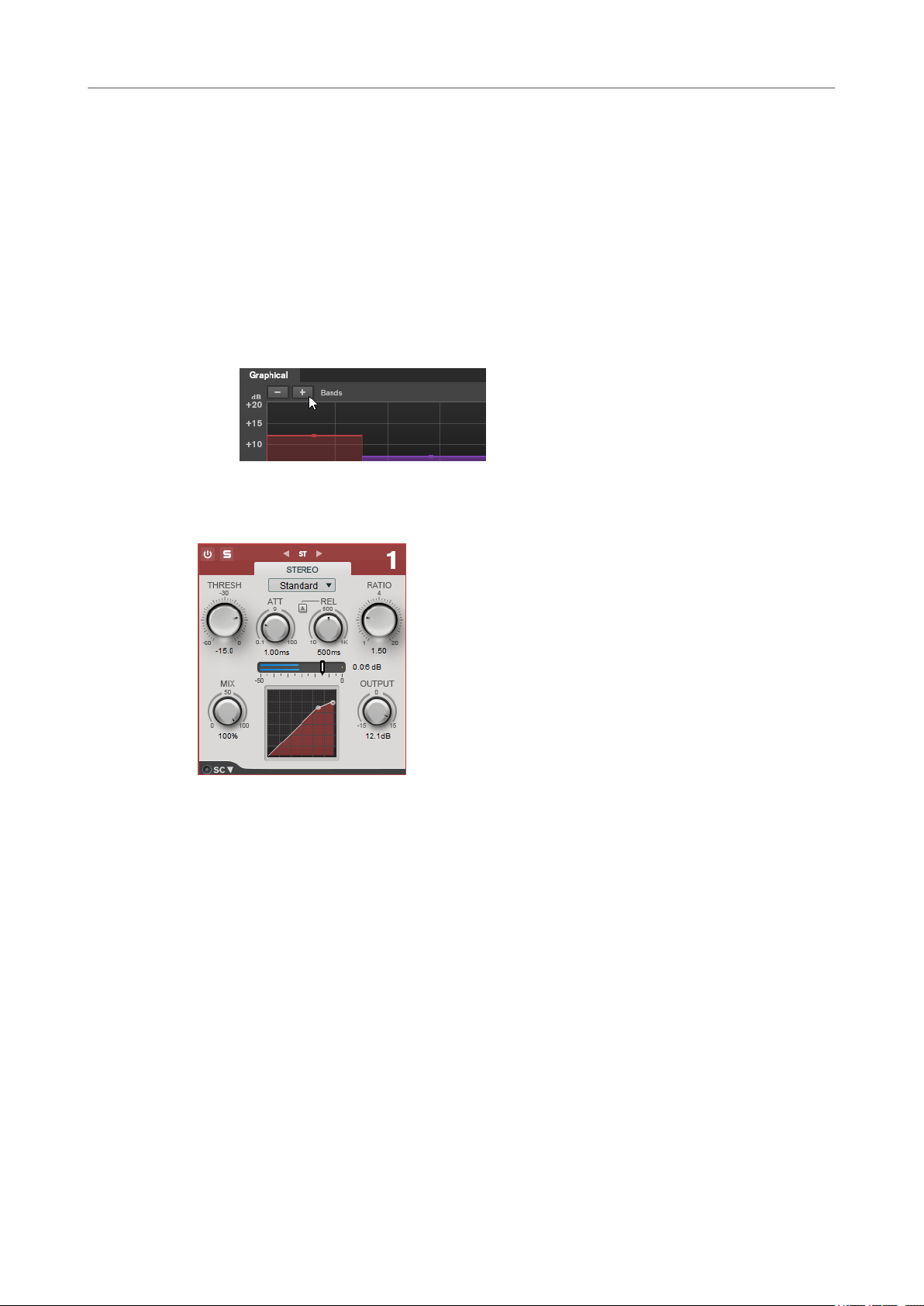
Maximizer
Maximizer raises the loudness of audio material without the risk of clipping. The limiting
amount is displayed between the input and the output meter.
Optimize
Determines the loudness of the signal.
Output
Sets the output level.
Compressor
The Compressor module allows a signal to be split into four frequency bands. You can specify
the level, bandwidth, and compressor characteristics for each band.
You can add two Compressor modules to the module chain, Compressor A and Compressor B.
Band Settings
13
Page 14
WaveLab-specic Plug-ins
MasterRig
On/Off
Activates/Deactivates the corresponding section.
Soloing Frequency Bands
To solo a frequency band, activate the S button in each section. Only one band can
be soloed at a time.
Channel Settings
Allow you to switch between left/right, stereo, and mid/side processing. In Left/
Right or Mid/Side processing mode, you can make different settings for the two
channels.
Add/Remove Band
Allow you to add and remove bands.
Standard
Allows you to create smooth compression effects.
THRESH (-60 to 0 dB)
Signal levels above the set threshold trigger the compressor.
ATT (0.1 to 100 ms)
Determines how fast the compressor responds. If the attack time is long, more of the
initial part of the signal passes through unprocessed.
REL (10 to 1000 ms)
Sets the time after which the gain returns to its original level. If Auto Release is
activated, the plug-in automatically
nds a suitable release setting for the audio.
Ratio
Sets the amount of gain reduction applied to signal above the set threshold.
Mix
Sets the level balance between the dry signal and the wet signal.
Compressor curve display
Graphically illustrates the compressor curve that is shaped according to the
Threshold and Ratio parameter settings.
14
Page 15
WaveLab-specic Plug-ins
MasterRig
Output
Sets the output gain.
Side-Chain
Opens the Side-Chain settings.
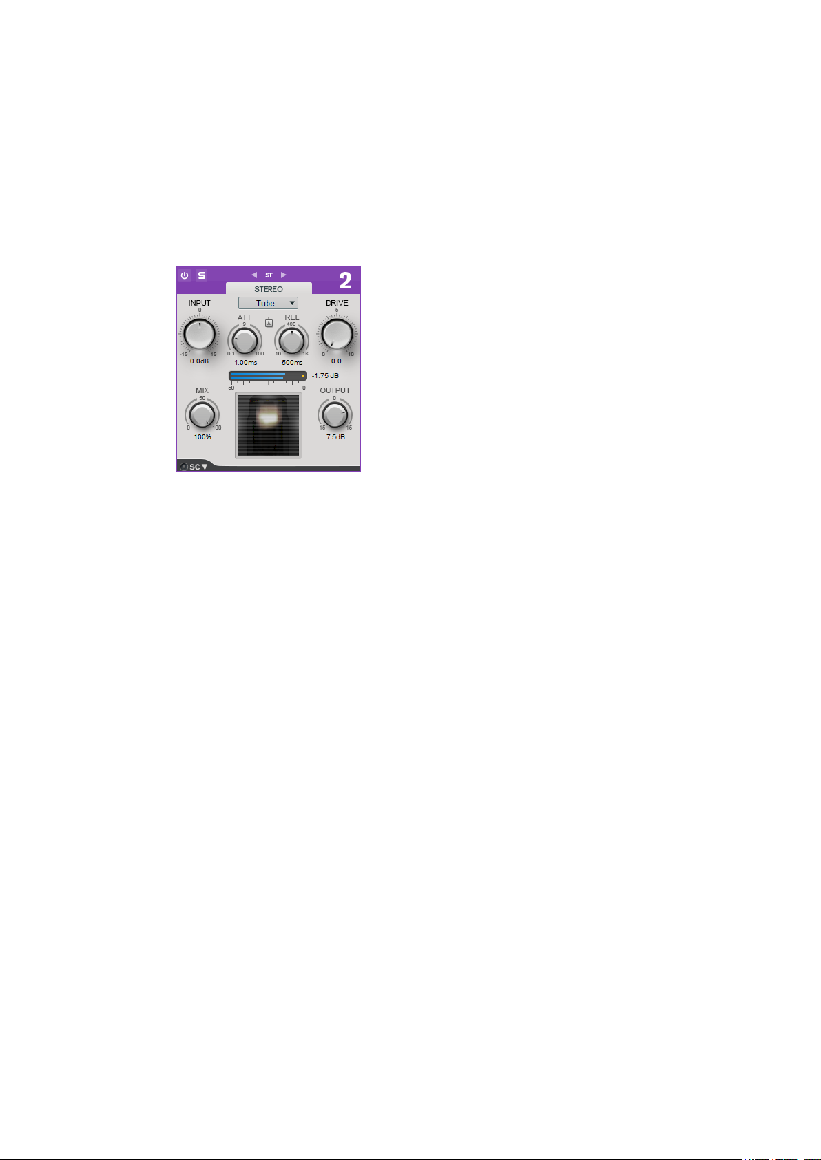
Tube
This versatile compressor with integrated tube-simulation allows you to produce smooth and
warm compression effects.
Input
In combination with the Output setting, this parameter determines the compression
amount. The higher the input gain setting and the lower the output gain setting, the
more compression is applied.
ATT (0.1 to 100 ms)
Determines how fast the compressor responds. If the attack time is long, more of the
initial part of the signal passes through unprocessed.
REL (10 to 1000 ms)
Sets the time after which the gain returns to its original level. If Auto Release is
activated, the plug-in automatically nds the best release setting for the audio.
Drive
Controls the amount of tube saturation.
Mix
Sets the level balance between the dry signal and the wet signal.
Output
Sets the output gain.
Side-Chain
Opens the Side-Chain settings.
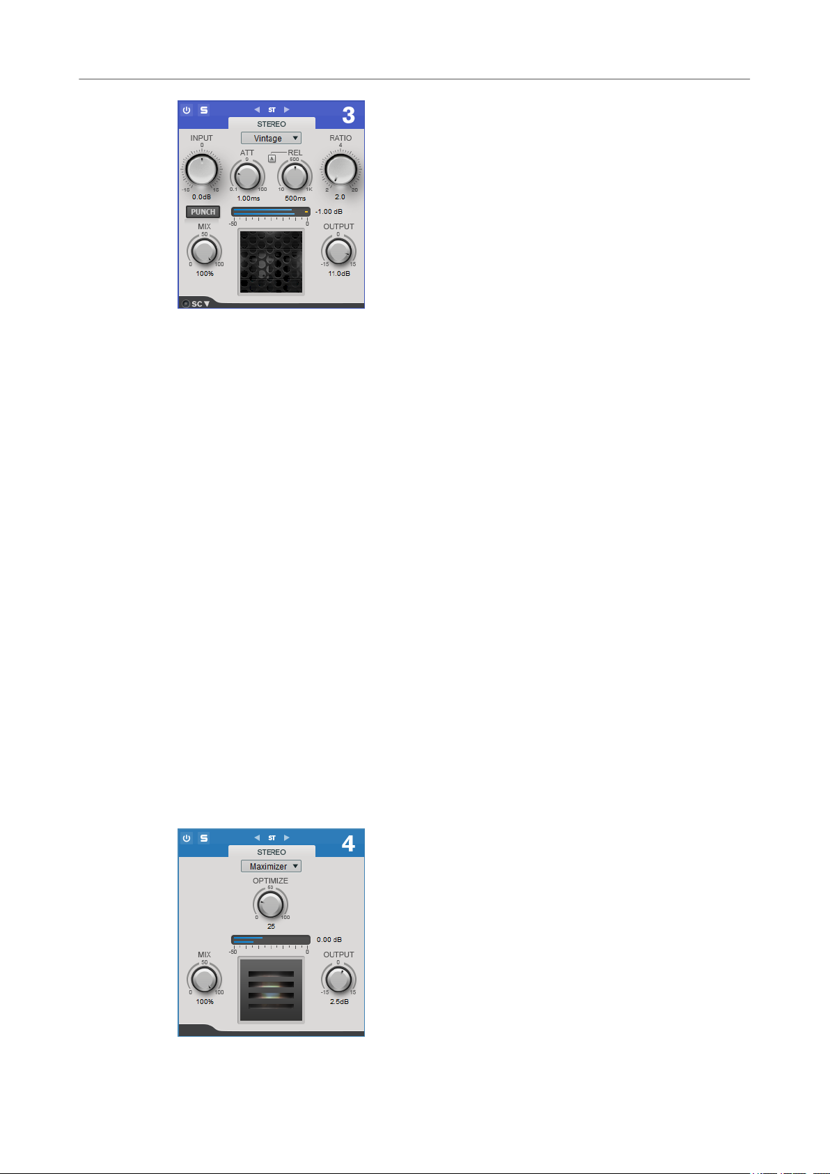
Vintage
Vintage Compressor is modeled after vintage type compressors.
15
Page 16
WaveLab-specic Plug-ins
MasterRig
Input
In combination with the Output setting, this parameter determines the compression
amount. The higher the input gain setting and the lower the output gain setting, the
more compression is applied.
ATT (0.1 to 100 ms)
Determines how fast the compressor responds. If the attack time is long, more of the
initial part of the signal passes through unprocessed.
REL (10 to 1000 ms)
Sets the time after which the gain returns to its original level. If Auto Release is
activated, the plug-in automatically
material.
Ratio
Sets the amount of gain reduction that is applied to signals above the set threshold.
Attack Mode (Punch)
If this option is activated, the early attack phase of the signal is preserved, retaining
the original punch in the audio material, even with short Attack settings.
Mix
Sets the level balance between the dry signal and the wet signal.
Output
Sets the output gain.
Side-Chain
Opens the Side-Chain settings.
nds the best release setting for the audio
Maximizer
16
Page 17
WaveLab-specic Plug-ins
MasterRig
Optimize
Determines the loudness of the signal.
Mix
Sets the level balance between the dry signal and the wet signal.
Output
Sets the output gain.
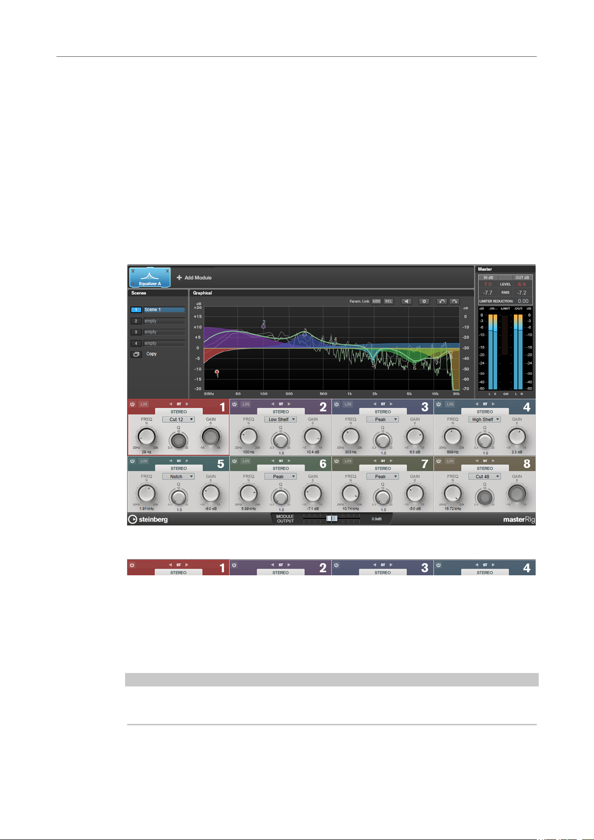
Equalizer
The Equalizer module is a high-quality 8-band parametric stereo equalizer with 8 fully
parametric mid-range bands. The low and high bands can act as either shelving lter, as peak
lter (band-pass), or as cut lter (low-pass/high-pass, band 1 and 8 only).
You can add two Equalizer modules to the module chain, Equalizer A and Equalizer B.
Band Settings
On/Off
Activates/Deactivates the corresponding section.
Channel Settings
Allow you to switch between left/right, stereo, and mid/side processing. In Left/
Right or Mid/Side processing mode, you can make different settings for the two
channels.
IMPORTANT
When using Mid/Side processing mode, we recommend that you activate Linear Phase in order
to avoid unwanted sound colorization.
17
Page 18
WaveLab-specic Plug-ins
MasterRig
Linear Phase
Activates/Deactivates linear phase mode for the corresponding band.
Linear phase mode avoids unwanted frequency dependent phase shifts of the audio
signal that might occur with standard minimum phase equalizing.
NOTE
● Linear phase mode leads to an increase in latency.
● In rare cases, for example, when using low cut ltering with a high slope for
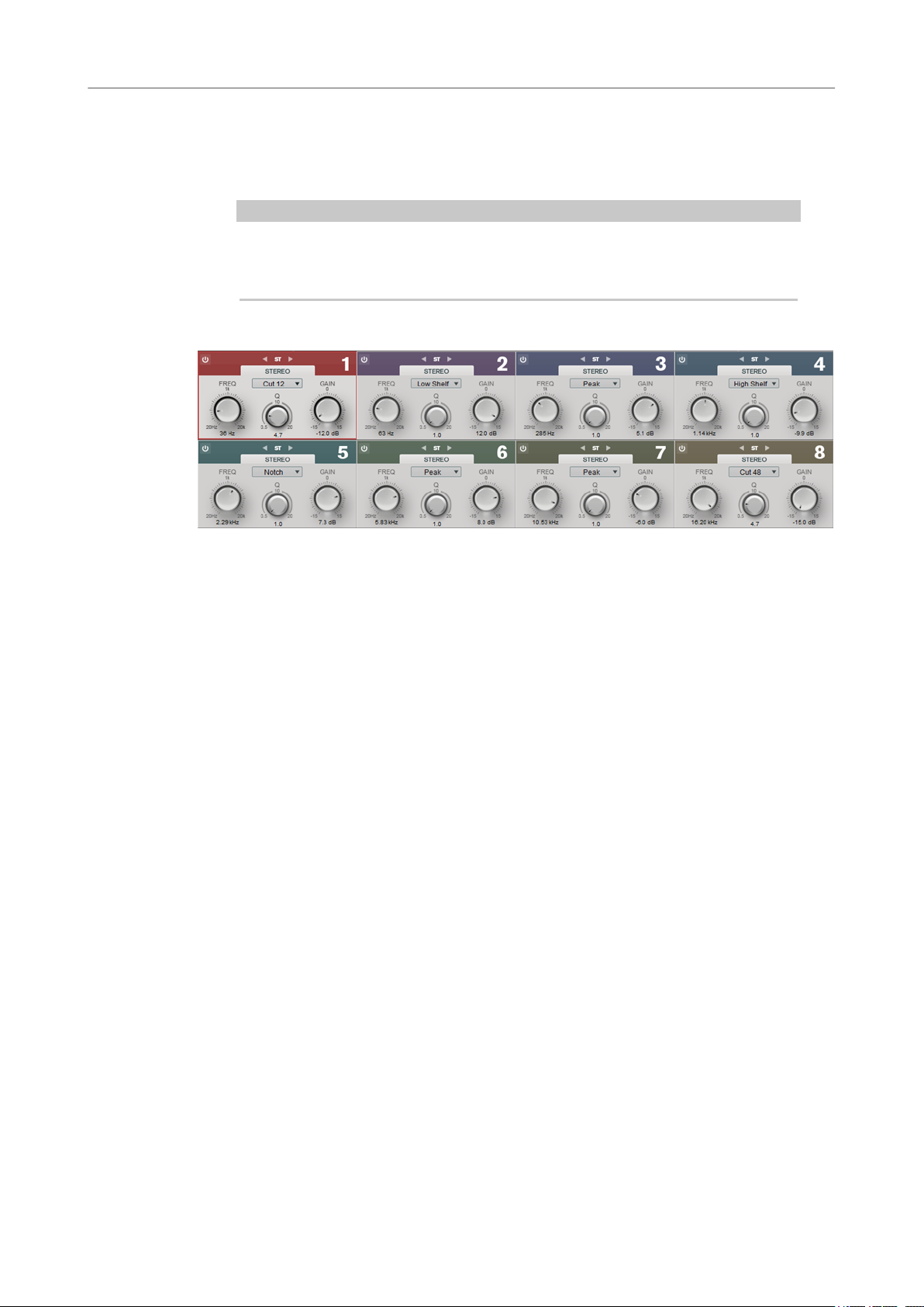
Equalizer Section
bass signals, also an unwanted pre-ringing effect may be audible.
Type
You can choose between the EQ types Low Shelf, Peak, High Shelf, and Notch. For
band 1 and 8, you can also select the types Cut 12, Cut 24, and Cut 48.
● Low Shelf boosts or attenuates frequencies below the cutoff frequency by the
specied amount.
● High Shelf boosts or attenuates frequencies above the cutoff frequency by the
specied amount.
● Peak boosts or attenuates frequencies at the set frequency value with a bell
shaped lter.
● Notch boosts or attenuates frequencies at the set frequency value with a very
narrow
● Cut attenuates frequencies below (band 1) or above (band 8) the set
frequency. You can choose between different slopes: 6 dB, 12 dB, 24 dB, 48
dB, or 96 dB per octave.
FREQ (20 to 20000 Hz)
Sets the frequency of the corresponding band.
Q
Controls the width of the corresponding band.
Gain (-15 to +15 dB)
Sets the amount of attenuation/boost for the corresponding band.
lter.
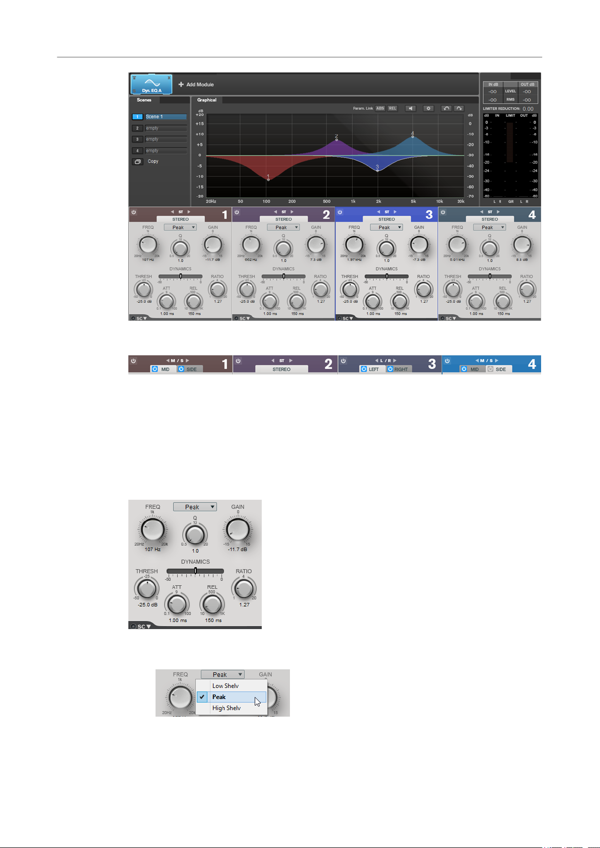
Dynamic EQ
Dynamic EQ allows you to adjust frequencies and lets you determine when and how the EQ is
applied depending on the dynamics of the audio material.
You can add two Dynamic EQ modules to the module chain, Dynamic EQ A and Dynamic EQ B.
18
Page 19
WaveLab-specic Plug-ins
MasterRig
Band Settings
On/Off
Activates/Deactivates the corresponding section.
Channel Settings
Allow you to switch between left/right, stereo, and mid/side processing. In Left/
Right or Mid/Side processing mode, you can make different settings for the two
channels.
Equalizer Section
Type pop-up menu
Allows you to select the EQ types.
● Low Shelf boosts or attenuates frequencies below the cutoff frequency by the
specied amount.
19
Page 20

WaveLab-specic Plug-ins
MasterRig
● Peak boosts or attenuates frequencies at the set frequency value with a bell
● High Shelf boosts or attenuates frequencies above the cutoff frequency by the
FREQ (20 to 20000 Hz)
Sets the frequency of the corresponding band.
Q
Controls the width of the corresponding band.
Gain (-15 to +15 dB)
Sets the amount of attenuation/boost for the corresponding band.
THRESH (-50 to 0 dB)
Determines the threshold level. Only signal levels above the threshold are processed.
ATT (0.1 to 100 ms)
Determines how fast Dynamic EQ responds to signals above the threshold. If the
attack time is long, more of the early part of the signal passes through unprocessed.
REL (10 to 1000 ms)
Sets the time after which Dynamic EQ returns to its original level when the signal
drops below the threshold.
shaped lter.
specied amount.
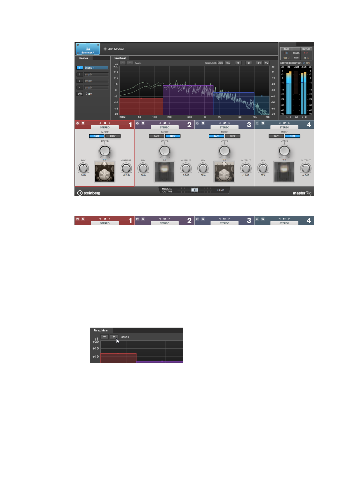
Saturator
Ratio
The higher the level of the input signal is above the threshold, the more ltering
occurs. Low ratio values mean that the lter starts to boost or attenuate smoothly
above the threshold. High ratio values mean that the lter starts to work almost
immediately.
Side-Chain
Opens the Side-Chain settings.
RELATED LINKS
Side-Chain Settings on page 8
The Saturator module allows you to simulate the sound of analog tubes, and the saturation and
compression effect when recording on analog tape machines.
You can add two Saturator modules to the module chain, Saturator A and Saturator B.
20
Page 21
WaveLab-specic Plug-ins
MasterRig
Band Settings
On/Off
Activates/Deactivates the corresponding section.
Soloing Frequency Bands
To solo a frequency band, activate the S button in each section. Only one band can
be soloed at a time.
Channel Settings
Allow you to switch between left/right, stereo, and mid/side processing. In Left/
Right or Mid/Side processing mode, you can make different settings for the two
channels.
Add/Remove Band
Allow you to add and remove bands.
21
Page 22
WaveLab-specic Plug-ins
MasterRig
Saturator Section
Tape/Tube
Allows you to switch between tube saturation and tape saturation.
● Tube saturation simulates the saturation of analog tube compressors.
● Tape saturation simulates the saturation and compression effect of analog
Drive
Controls the amount of saturation.
tape machine recordings.
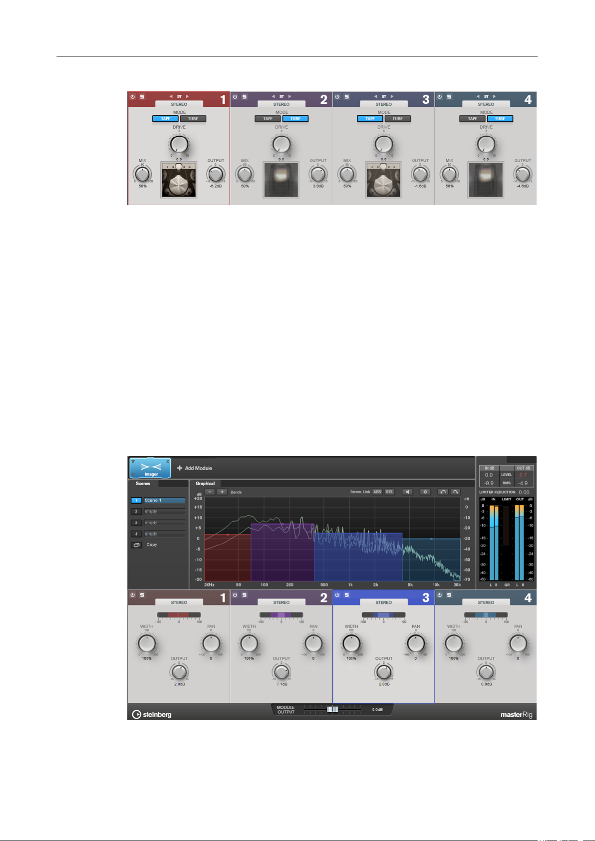
Imager
Mix
Sets the level balance between the dry signal and the wet signal.
Output
Sets the output gain.
The Imager module allows you to expand or reduce the stereo width of your audio in up to four
bands. This way you can independently adjust the stereo image in dened frequency domains.
22
Page 23
WaveLab-specic Plug-ins
Peak Master
Band Settings
On/Off
Activates/Deactivates the corresponding section.
Soloing Frequency Bands
To solo a frequency band, activate the S button in each section. Only one band can
be soloed at a time.
Add/Remove Band
Allow you to add and remove bands.
Imager Section
Width
Pan
Output
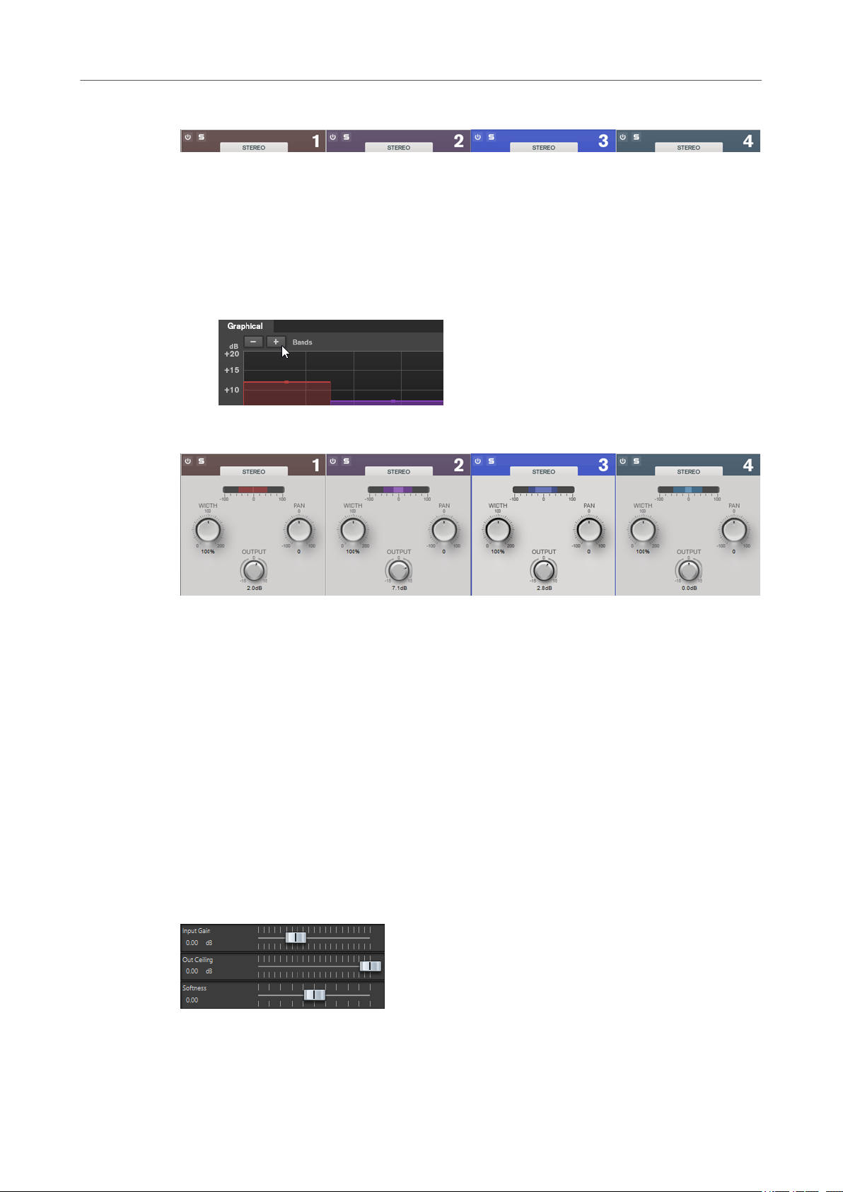
Peak Master
This is a basic plug-in that minimizes peaks in your audio le, allowing a louder mix without
clipping. It is useful in taming dynamic instruments.
It is primarily used as a brickwall limiter. For example, you can limit audio peaks without altering
the rest of the audio signal. In this case, set Input Gain to 0 dB and Out Ceiling to 0 dB, to
achieve a clip-free audio signal. When used in this way, Peak Master is an excellent plug-in to
succeed a resampler plug-in, and to proceed a dithering plug-in.
Allows you to control the stereo width per band.
Allows you to pan the signal left/right.
Sets the output level for each band.
Input Gain
Values range from -12 dB to 24 dB.
23
Page 24
WaveLab-specic Plug-ins
RestoreRig
Out Ceiling
This is the maximum level of the output signal. Values range from -18 dB to 0 dB.
Softness
This governs the speed at which the signal becomes unaffected after limiting has
been triggered on some samples. Values range from -5 to +5.
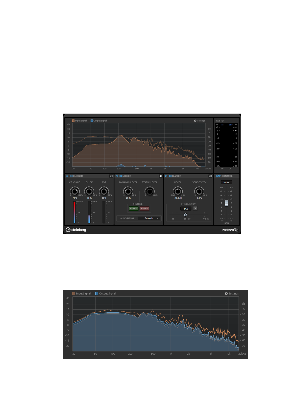
RestoreRig
RestoreRig allows you to remove noise from an audio recording with different restoration
modules. The noise can be an impulsive noise (DeClicker), an ambient noise (DeNoiser), or a low
tonal noise (DeBuzzer)
Main Layout
Input Signal/Output Signal
Displays the input signal and the output signal of the restored signal. The vertical value scale to
the left shows the gain level of the input and output signals. The horizontal scale shows the
frequency range.
24
Page 25
WaveLab-specic Plug-ins
RestoreRig
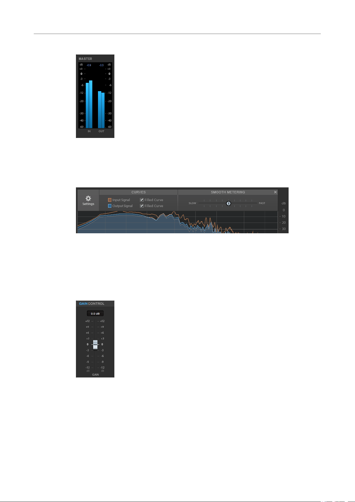
Master
The input/output meter provides a peak level meter.
The maximum values for input/output peak level are displayed above the meter display. To reset
all maximum values, click any of the values.
Settings
Modules
Filled Curve
Allows you to ll the curves of the input signal and the output signal.
Smooth Metering
Determines the reaction time of the display. Lower values result in faster reaction
times.
Gain Control
The Gain Control allows you to set the master gain for the modules.
The modules DeClicker, DeNoiser, and DeBuzzer allow you to remove different kinds of noises.
To activate or deactivate a module, click Activate/Deactivate on the left of the module
●
name.
25
Page 26
WaveLab-specic Plug-ins
RestoreRig
● To only listen to the sound that has been removed from the audio, click the Noise
Listening Mode button of the module that you want to hear.
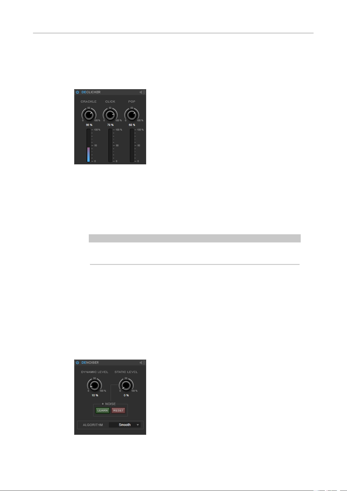
DeClicker
DeClicker allows you to remove clicks from audio material.
Activate/Deactivate DeClicker
Activates/Deactivates the module.
DeNoiser
Noise Listening Mode
Allows you to listen to the signal that has been removed from the original audio
material.
Meters
Allow you to monitor the quantity of impulsive noise that is removed from the signal.
NOTE
Avoid letting the meter reach the red region, as this can produce destructive
artifacts.
Crackle
Allows you to remove very short impulsive noise from the audio signal.
Click
Allows you to remove medium-sized impulsive noise from the audio signal.
Pop
Allows you to remove long impulsive noise from the audio signal.
DeNoiser allows you to remove noise from the audio material.
26
Page 27
WaveLab-specic Plug-ins
RestoreRig
Activate/Deactivate DeNoiser
Activates/Deactivates the module.
Noise Listening Mode
Allows you to listen to the signal that has been removed from the original audio
material.
Dynamic Level
Allows you to remove noise that evolves over time from the audio signal.
Static Level
Allows you to remove noise that does not evolve over time from the audio signal. The
Learn option allows you to dene the stationary noise.
Noise
The Noise options allow you to dene a section in an audio le that contains a static
noise that you want to remove. When you then render the audio le, you can remove
the recorded static noise from the audio signal.
1. Play back the audio section that contains the noise that you want to remove
2. Use the Static Level dial to set the level.
3. To remove the recorded static noise in the audio le, render the audio le.
and click Learn.
RestoreRig records the audio for a few seconds to detect the static noise.
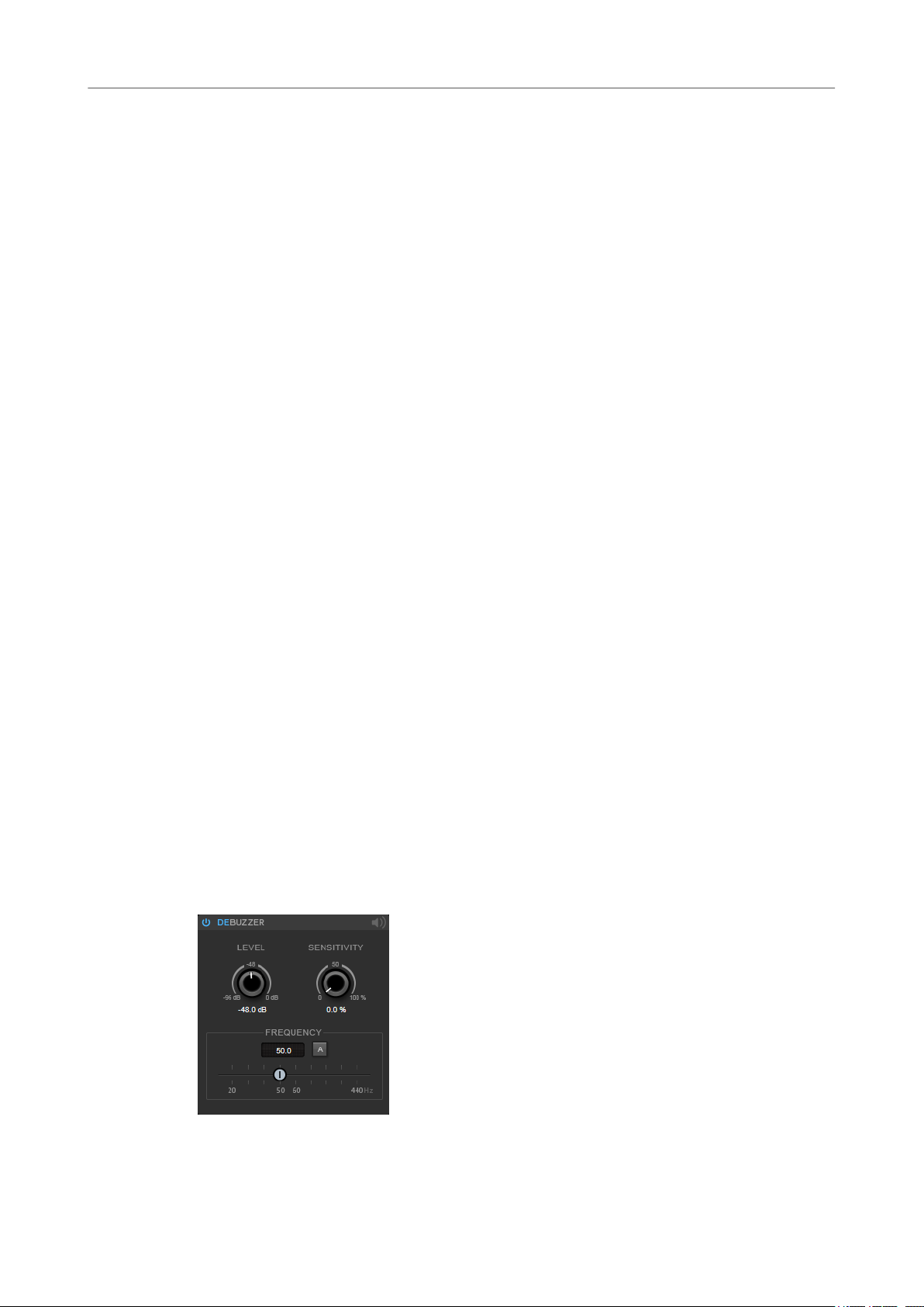
DeBuzzer
If you want to record the static noise at another audio section, click Reset, play back
another audio section, and click Learn again.
Algorithm
Allows you to select different DeNoiser algorithms. Depending on the audio
material, different modes can affect the DeNoiser quality.
● Smooth is sucient for most uses.
● Use Musical for harmonic content with low rhythmic or transient components.
● Use Rhythmic for drum and percussive content.
● Use Strong if the noise level reduction is more important than the accuracy of
the noise reduction.
● Use Speech for vocal content.
DeBuzzer allows you to remove harmonic noise with a fundamental frequency that should be
around 50 to 60 Hz.
Activate/Deactivate DeBuzzer
Activates/Deactivates the module.
27
Page 28
WaveLab-specic Plug-ins
Silence
Noise Listening Mode
Allows you to listen to the signal that has been removed from the original audio
material.
Level
Allows you to dene the reduction of the noise in dB.
Sensitivity
Allows you to dene how sensitive the reduction will be to the current audio level. At
0 %,
sensitivity values, the level is dynamically dened in a range between 0 dB and the
Level value. This reduces the buzz when the audio level is low and does not affect
the audio when the audio level is high.
Frequency
Allows you to dene the value of the fundamental frequency.
Auto
If this option is activated, DeBuzzer automatically detects the fundamental
frequency of the current most prominent harmonic tone.
NOTE
DeBuzzer reduces the current harmonic noise with the Level value. At higher
Once you have detected the frequency that you want to remove, deactivate Auto.
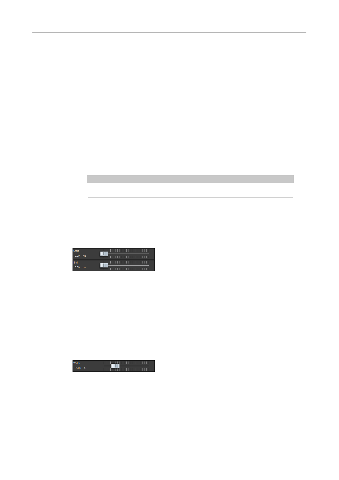
Silence
This plug-in provides a simple way of inserting a precise period of silence at the start or at the
end of an audio le. Use this plug-in to add silence at the end of a le, so that the tail of a reverb
plug-in does not cut immediately at the end of the
Start
Use the slider to insert from 0 to 60,000 ms of silence at the start of the le.
End
Use the slider to insert from 0 to 60,000 ms of silence at the end of the le.
Stereo Expander
This plug-in is a stereo width enhancer that makes a stereo signal sound wider. It gives better
results from real stereo material, as opposed to mono channels panned to different positions in
the stereo image.
le.
Width
Higher values result in a greater stereo width. Usually, you set Width to values
between 0 % and 20 %. Higher values can be used for special effects.
28
Page 29
Steinberg VST 3 Plug-ins
In WaveLab there is no limitation to the use of VST plug-ins. They can be used wherever plug-ins
can be inserted.
● You can specify which VST plug-ins should be available in the Effects pane and Final
Processing/Dithering pane of the Master Section by using the Plug-in Settings dialog.
● VST plug-ins have their own preset handling. You can save or load effect programs
(presets).
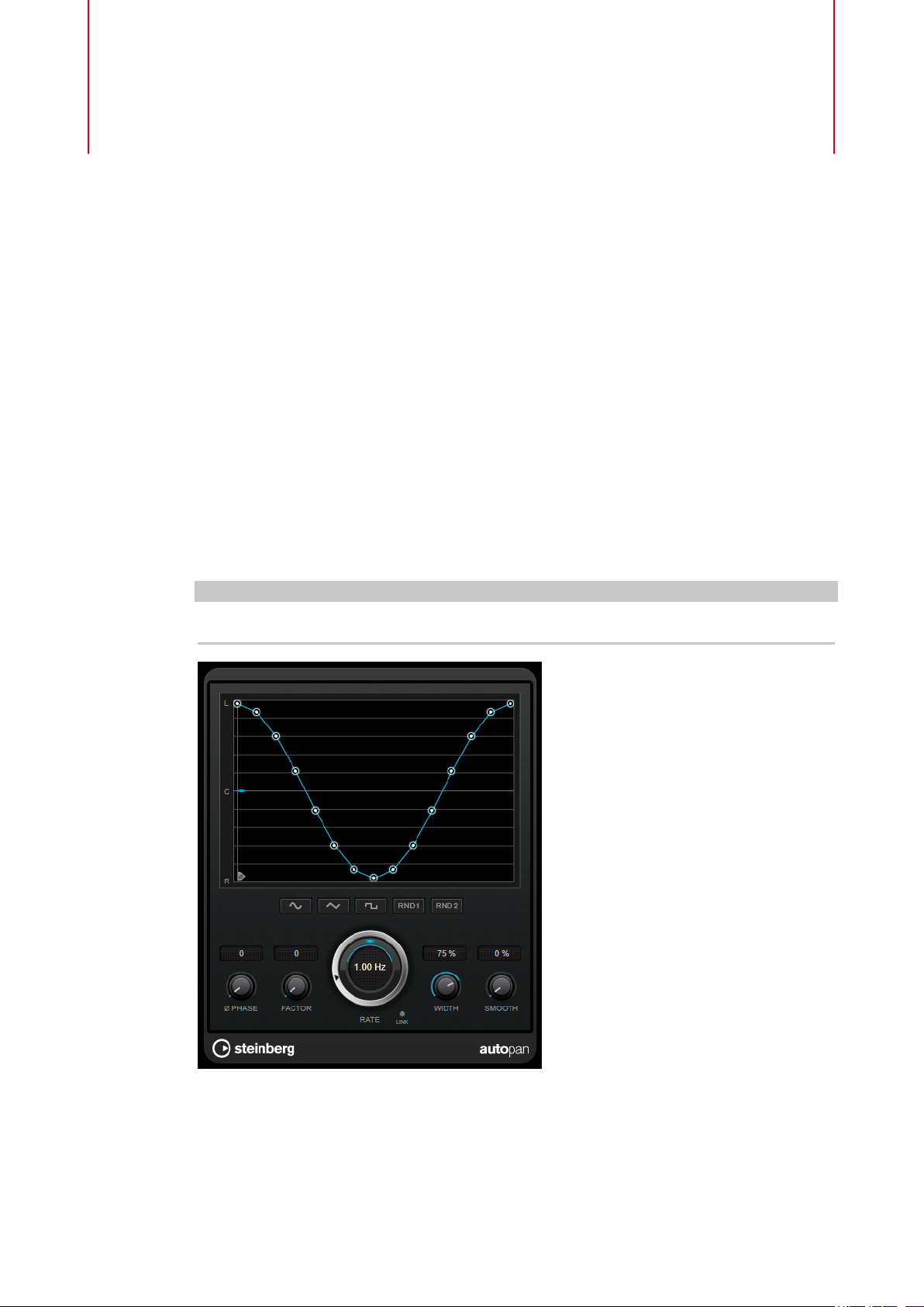
AutoPan
This auto-pan effect provides several parameters to modulate the left/right stereo position. You
can use presets or create individual curves for the modulation waveform. AutoPan also allows
for chopping effects by linking the modulation of left and right channel.
NOTE
The panning effect of this plug-in works only on stereo tracks.
Waveform display
Shows the shape of the modulation waveform and allows you to manually adjust it.
To draw an individual curve, click a node and move the mouse. To draw a straight
line, Shift-click a node and move the mouse.
29
Page 30

Steinberg VST 3 Plug-ins
Brickwall Limiter
Waveform preset buttons
Phase
Rate
Allow you to select presets for the modulation waveform.
● Sine creates a smooth sweep.
● Triangle creates a ramp, that is, a linear movement from full right to full left
and back.
● Square creates an instant jump to full right, then to full left, and then back to
center.
● Random One Shot creates a random curve. Click this button again to create a
new random curve.
● Random Continuous automatically creates a new random curve after each
period.
Sets the offset for the starting point of the curve. If multiple AutoPan plug-ins are
used on different tracks, for example, different offset settings for each track allow for
a more organic overall sound.
Sets the auto-pan speed in Hertz and shows the movement within the panorama.
Link
If this button is activated, the left and right channel are modulated simultaneously.
This results in a chopping effect instead of auto-panning.
In this mode, Width sets the intensity of the volume modulation.
Width
Sets the amount of deection to the left and right side of the stereo panorama. If
Link is activated, this parameter sets the intensity of the volume modulation.
Smooth
Allows you to smooth the transition between individual steps of the panorama curve.
Brickwall Limiter
Brickwall Limiter ensures that the output level never exceeds a set limit.
Due to its fast attack time, Brickwall Limiter can reduce even short audio level peaks without
creating audible artifacts. However, this plug-in creates a latency of 1ms. Brickwall Limiter
features separate meters for input, output, and the amount of limiting. Position this plug-in at
the end of the signal chain, before dithering.
30
Page 31
Steinberg VST 3 Plug-ins
Channel Extractor
Threshold (-20 to 0 dB)
Release (3 to 1000 ms or Auto mode)
Link
Detect Intersample Clipping
NOTE
Brickwall Limiter is designed for the reduction of occasional peaks in the signal. If the Gain
Reduction meter indicates constant limiting, try raising the threshold or lowering the overall
level of the input signal.
Determines the level where the limiter kicks in. Only signal levels above the set
threshold are processed.
Sets the time after which the gain returns to the original level when the signal drops
below the threshold. If the Auto button is activated, the plug-in automatically nds
the best release setting for the audio material.
If this button is activated, Brickwall Limiter uses the channel with the highest level
to analyze the input signal. If the button is deactivated, each channel is analyzed
separately.
If this option is activated, Brickwall Limiter uses oversampling to detect and limit
signal levels between two samples to prevent distortion when converting digital
signals into analog signals.
Channel Extractor
This plug-in allows you to only keep the left or the right channel of a stereo stream.
Channel
Lets you select whether to keep the left or the right channel of the stereo stream.
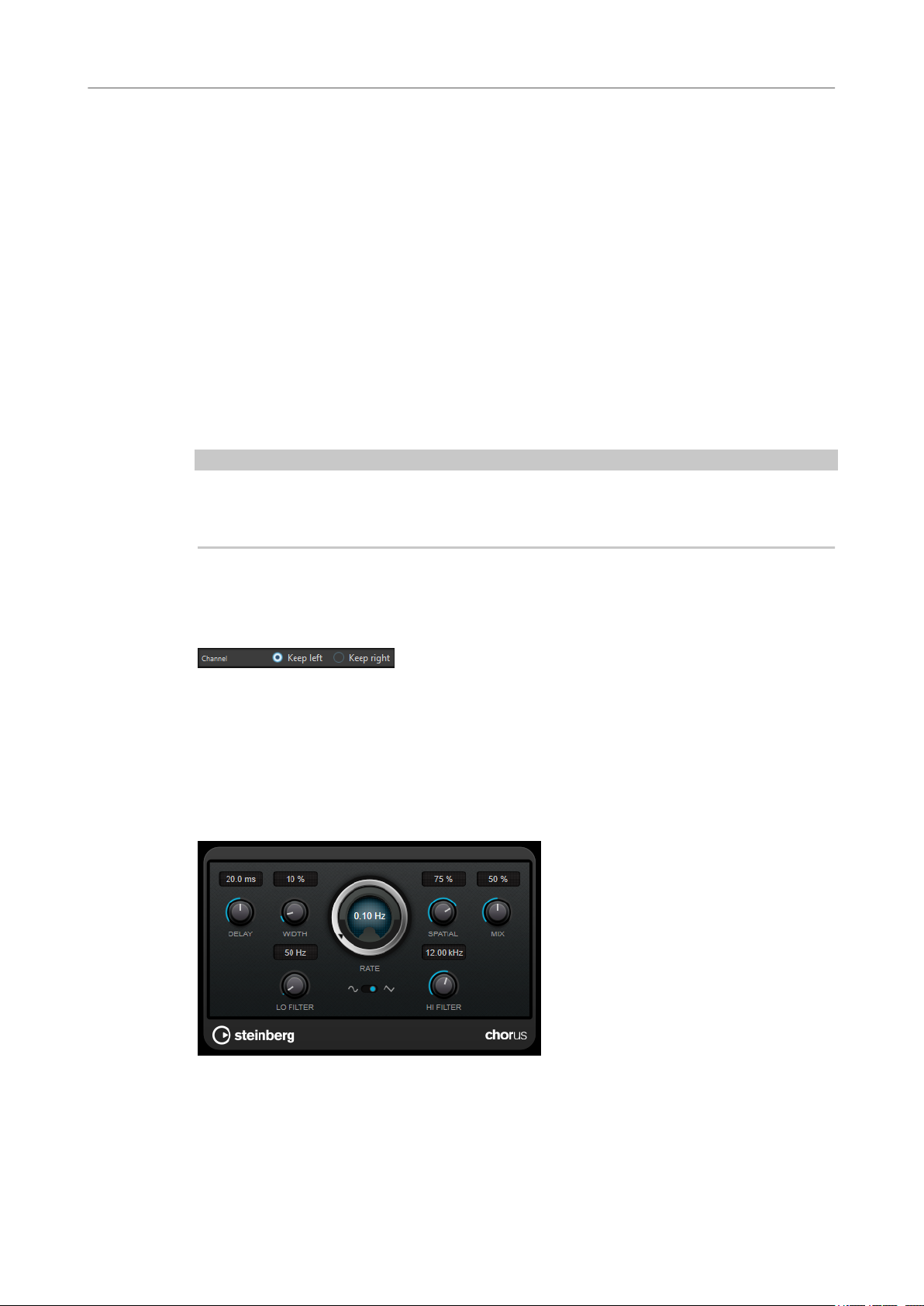
Chorus
This plug-in is a single-stage chorus effect. It doubles the audio that is sent into it with a slightly
detuned version.
Delay
Affects the frequency range of the modulation sweep by adjusting the initial delay
time.
31
Page 32
Steinberg VST 3 Plug-ins
Compressor
Width
Spatial
Mix
Rate
Waveform Shape
Lo Filter/Hi Filter
Sets the depth of the chorus effect. Higher settings produce a more pronounced
effect.
Sets the stereo width of the effect. Turn clockwise for a wider stereo effect.
Sets the level balance between the dry signal and the wet signal. If the effect is used
as a send effect, set this parameter to the maximum value, as you can control the
dry/effect balance with the send level.
Allows you to set the sweep rate freely with the Rate knob.
Allows you to select the modulation waveform, altering the character of the chorus
sweep. A sine and a triangle waveform are available.
Allow you to roll off low and high frequencies of the effect signal.
NOTE
If side-chaining is supported, the modulation can also be controlled from another signal source
via the side-chain input. If the side-chain signal exceeds the threshold, the modulation is
controlled by the side-chain signal’s envelope. For a description of how to set up side-chain
routing, see the
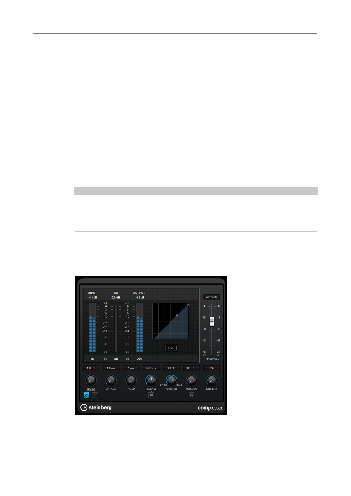
Compressor
Compressor reduces the dynamic range of the audio, making softer sounds louder or louder
sounds softer, or both.
Operation Manual.
Compressor features a separate display that graphically illustrates the compressor curve that is
shaped according to the Threshold and Ratio parameter settings. Compressor also features a
32
Page 33

Steinberg VST 3 Plug-ins
Compressor
Gain Reduction meter that shows the amount of gain reduction in dB, Soft knee/Hard knee
compression modes, and a program-dependent auto feature for the Release parameter.
Threshold (-60 to 0 dB)
Ratio
Soft Knee
High Ratio
Make-Up (0 to 24 dB or Auto mode)
Determines the level where the compressor kicks in. Only signal levels above the set
threshold are processed.
Sets the amount of gain reduction applied to signals above the set threshold. A ratio
of 3:1 means that for every 3 dB the input level increases, the output level increases
by 1 dB.
If this button is deactivated, signals above the threshold are compressed instantly
according to the set ratio (hard knee). If Soft Knee is activated, the onset of
compression is more gradual, producing a less drastic result.
Sets the ratio to a xed value of 20:1.
Compensates for output gain loss caused by compression. If Auto Make-Up Gain is
activated, the output is automatically adjusted for gain loss.
Dry Mix
Mixes the dry input signal to the compressed signal.
Attack (0.1 to 100 ms)
Determines how fast the compressor responds to signals above the set threshold. If
the attack time is long, more of the early part of the signal passes through
unprocessed.
Hold (0 to 5000 ms)
Sets the time the applied compression affects the signal after exceeding the
threshold. Short hold times are useful for DJ-style ducking, while longer hold times
are required for music ducking, for example, when working on a documentary lm.
Release (10 to 1000 ms or Auto mode)
Sets the time after which the gain returns to its original level when the signal drops
below the threshold. If Auto Release is activated, the plug-in automatically nds the
best release setting for the audio material.
Analysis (Pure Peak to Pure RMS)
Determines whether the input signal is analyzed according to peak or RMS values, or
a mixture of both. A value of 0 is pure peak and 100 pure RMS. RMS mode operates
using the average power of the audio signal as a basis, whereas
operates more on peak levels. As a general guideline, RMS mode works better on
material with few transients such as vocals, and Peak mode works better for
percussive material with a lot of transient peaks.
Peak mode
Live
If this button is activated, the look-ahead feature of the effect is deactivated. Lookahead produces more accurate processing, but adds a
a trade-off. If Live mode is activated, there is no latency, which is better for live
processing.
33
specic amount of latency as
Page 34
Steinberg VST 3 Plug-ins
CurveEQ
CurveEQ
Voxengo CurveEQ is a spline equalizer for professional music and audio production applications.
CurveEQ shows the lter response you are designing by means of a spline, that is, a smooth
curvy line. This way you can see how the EQ alters the sound.
CurveEQ implements spectrum matching technology that allows you to transfer the spectral
shape of one recording to another. In other words, you can copy the frequency balance of
existing time-proven mixes so that other mixes can be improved. The
switched between linear-phase and minimum-phase modes. CurveEQ also features a
customizable spectrum analyzer. Furthermore, you can display, save, and load static spectrum
plots for comparison and matching purposes.
For detailed information about CurveEQ and its parameters, refer to the documentation
provided by Voxengo at http://www.voxengo.com.
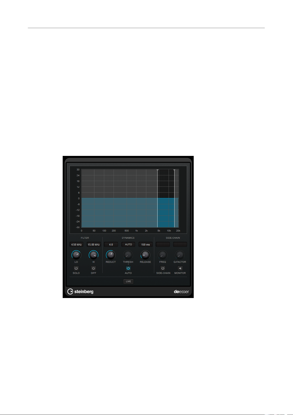
DeEsser
DeEsser reduces excessive sibilance, primarily for vocal recordings. It is a special type of
compressor that is tuned to be sensitive to the frequencies produced by the s-sound.
lters of CurveEQ can be
Close proximity microphone placement and equalizing can lead to situations where the overall
sound is just right, but there is a problem with sibilants.
Display
Shows the spectrum of the input signal.
● To adjust the frequency band, drag the border lines or click in the middle of the band and
drag.
● To change the width of the frequency band, hold Shift and drag to the left or right.
34
Page 35

Steinberg VST 3 Plug-ins
DeEsser
Filter
Lo/Hi
Solo
Diff
Sets the left and right border of the frequency band. You can set the frequency either
in Hz or as a note value. If you enter a note value, the frequency is automatically
displayed in Hz accordingly. For example, a note value of A3 sets the frequency to
440 Hz. When you enter a note value, you can also enter a cent offset. For example,
enter A5 -23 or C4 +49.
NOTE
Make sure that you enter a space between the note and the cent offset. Only in this
case, the cent offsets are taken into account.
Solos the frequency band. This helps you to nd the appropriate position and width
of that band.
Plays back what DeEsser removed from the signal. This help you to adjust the
frequency band, threshold, and reduction parameters, so that only sharp s-sounds
are removed, for example.
Dynamics
Reduction
Controls the intensity of the de-essing effect.
Threshold (-50 to 0 dB)
If the Auto option is deactivated, you can use this control to set a threshold for the
incoming signal level above which the plug-in starts to reduce the sibilants.
Release (1 to 1000 ms)
Sets the time after which the de-essing effect returns to zero when the signal drops
below the threshold.
Auto
Automatically and continually sets an optimum threshold setting independent of the
input signal. The Auto option does not work for low-level signals (< -30 db peak
level). To reduce the sibilants in such a
le, set the threshold manually.
Side-Chain
Freq (25 Hz to 20 kHz)
If the Side-Chain button is activated, this sets the frequency of the lter. You can set
the frequency either in Hz or as a note value. If you enter a note value, the frequency
is automatically displayed in Hz accordingly. For example, a note value of A3 sets the
frequency to 440 Hz. When you enter a note value, you can also enter a cent offset.
For example, enter A5 -23 or C4 +49.
NOTE
Make sure that you enter a space between the note and the cent offset. Only in this
case, the cent offsets are taken into account.
Q-Factor
If the Side-Chain button is activated, this sets the resonance or width of the lter.
35
Page 36
Steinberg VST 3 Plug-ins
Distortion
Side
Monitor
Live
Positioning the DeEsser in the Signal Chain
When recording a voice, the position of DeEsser in the signal chain is usually located after the
microphone pre-amp and before a compressor/limiter. This keeps the compressor/limiter from
unnecessarily limiting the overall signal dynamics.
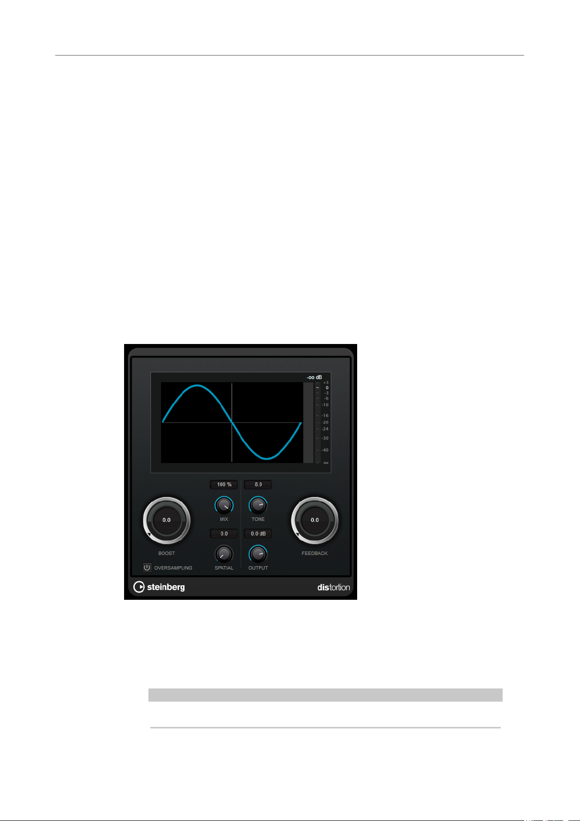
Distortion
Activates the internal side-chain lter. You can now shape the input signal according
to the lter parameters. Internal side-chaining can be useful for tailoring how the
gate operates.
Allows you to monitor the ltered signal.
If this button is activated, the look-ahead feature of the effect is deactivated. Lookahead produces more accurate processing, but adds a specic amount of latency as
a trade-off. If Live mode is activated, there is no latency, which is better for live
processing.
Distortion adds crunch to your tracks.
Boost
Increases the distortion amount.
Oversampling
Activates/Deactivates oversampling. Oversampling results in less artifacts for higher
distortion.
NOTE
If this parameter is activated, the effect requires more processing power.
36
Page 37
Steinberg VST 3 Plug-ins
DualFilter
Mix
Tone
Feedback
Spatial
Output
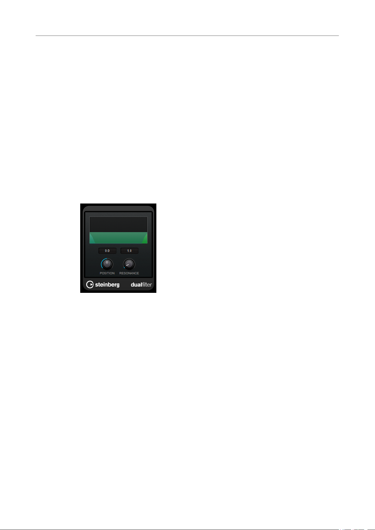
DualFilter
DualFilter lters out specic frequencies while allowing others to pass through.
Sets the level balance between the dry signal and the wet signal.
Changes the tonal characteristic of the output signal.
Feeds part of the output signal back to the effect input. Higher settings increase the
distortion effect.
Changes the distortion characteristics of the left and right channels, thus creating a
stereo effect.
Sets the output level.
Position
Sets the lter cutoff frequency. If you set this to a negative value, DualFilter acts as a
low-pass lter. Positive values cause DualFilter to act as a high-pass lter.
Resonance
Sets the sound characteristic of the lter. With higher values, a ringing sound is
heard.
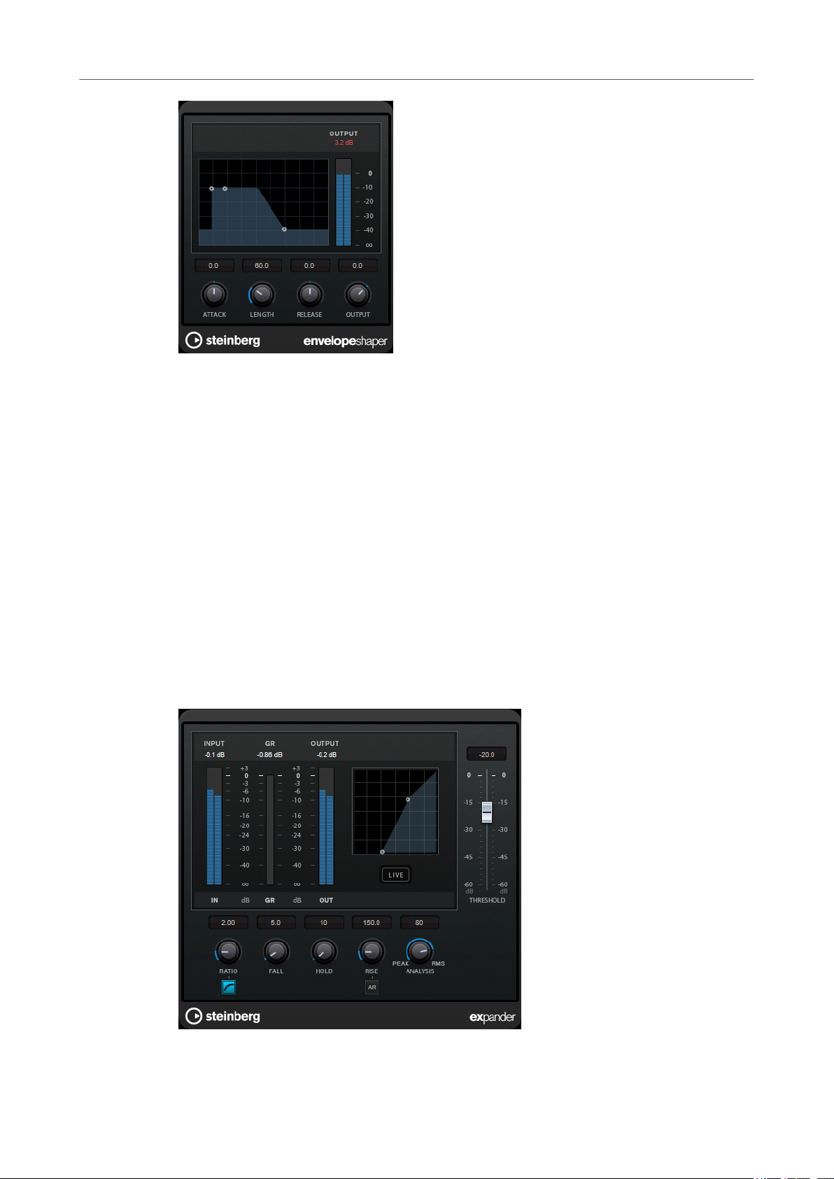
EnvelopeShaper
EnvelopeShaper can be used to attenuate or boost the gain of the attack and release phase of
audio material.
You can use the knobs or drag the breakpoints in the graphical display to change parameter
values. Be careful with levels when boosting the gain and if needed reduce the output level to
avoid clipping.
37
Page 38
Steinberg VST 3 Plug-ins
Expander
Attack (-20 to 20 dB)
Length (5 to 200 ms)
Sets the gain of the attack phase of the signal.
Sets the length of the attack phase.
Expander
Release
Sets the gain of the release phase of the signal.
Output
Sets the output level.
Expander reduces the output level in relation to the input level for signals below the set
threshold. This is useful if you want to enhance the dynamic range or reduce the noise in quiet
passages.
You can either use the knobs or drag the breakpoints in the graphical display to change the
Threshold and the Ratio parameter values.
38
Page 39

Steinberg VST 3 Plug-ins
Expander
Threshold
Ratio
Soft Knee
Fall (0.1 to 100 ms)
Hold (0 to 2000 ms)
Rise (10 to 1000 ms or Auto mode)
Determines the level where the expansion kicks in. Only signal levels below the set
threshold are processed.
Sets the amount of gain boost applied to signals below the threshold.
If this button is deactivated, signals below the threshold are expanded instantly
according to the set ratio (hard knee). If
expansion is more gradual, producing less drastic results.
Determines how fast the expander responds to signals below the set threshold. If
the fall time is long, more of the early part of the signal passes through unprocessed.
Sets the time the applied expansion affects the signal below the threshold.
Sets the time after which the gain returns to its original level when the signal
exceeds the threshold. If the Auto Rise button is activated, the plug-in automatically
nds the best rise setting for the audio material.
Soft Knee is activated, the onset of
Analysis (Pure Peak to Pure RMS)
Determines whether the input signal is analyzed according to peak or RMS values, or
a mixture of both. A value of 0 is pure peak and 100 pure RMS. RMS mode operates
using the average power of the audio signal as a basis, whereas
operates more on peak levels. As a general guideline, RMS mode works better on
material with few transients such as vocals, and Peak mode works better for
percussive material with a lot of transient peaks.
Live
If this button is activated, the look-ahead feature of the effect is deactivated. Lookahead produces more accurate processing, but adds a specic amount of latency as
a trade-off. If Live mode is activated, there is no latency, which is better for live
processing.
Peak mode
39
Page 40
Steinberg VST 3 Plug-ins
Frequency
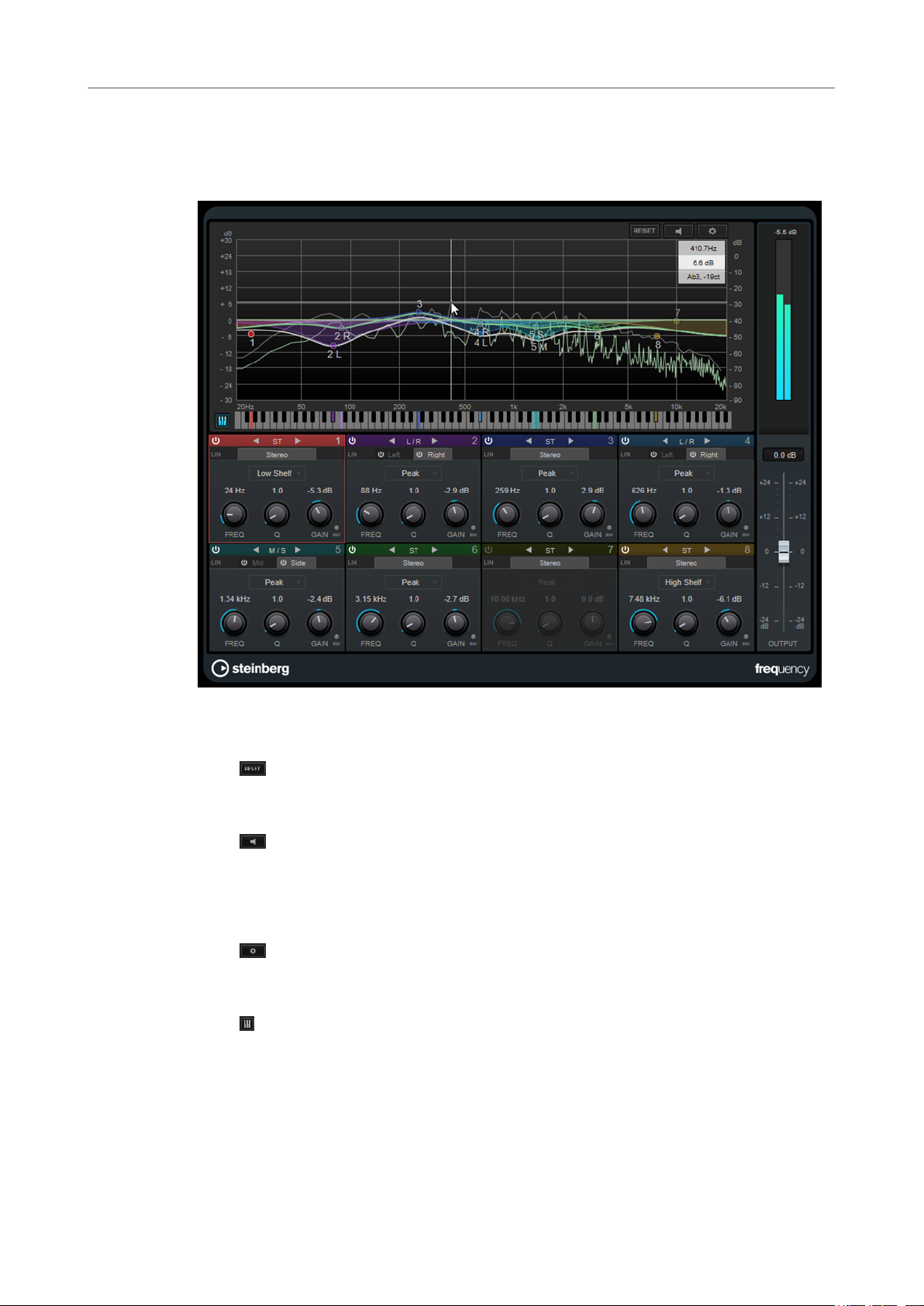
Frequency
Frequency is a high-quality equalizer with 8 fully parametric bands. The bands can act as either
shelving lter, as peak or notch lter (band-pass), or as cut lter (low-pass/high-pass).
Main Layout
Reset
Alt-click this button to reset all parameter values.
Auto Listen for Filters
If this option is activated and you edit a parameter of a band, the corresponding
frequency range is isolated. This helps you to focus on a particular frequency range
and allows you to locate unwanted frequencies in your audio.
Global Settings
Opens the settings dialog for the spectrum display.
Show/Hide Keyboard
Shows/Hides the keyboard below the graphical editor.
On the keyboard, color indicators reect the center frequencies of all active equalizer
bands. You can adjust the frequency of a band by dragging its color indicator. If you
drag the color indicator of a band to a key, the band is set to its exact frequency.
Output
Adjusts the overall output level.
40
Page 41
Steinberg VST 3 Plug-ins
Frequency
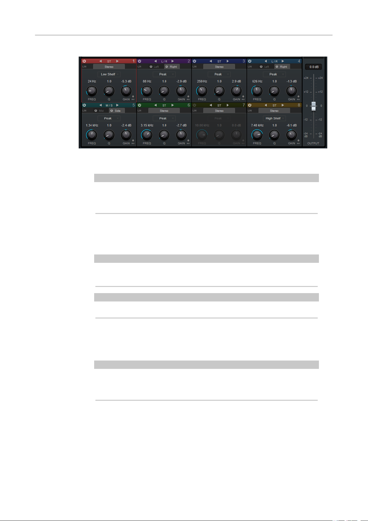
Band Settings
Activate/Deactivate Band
Activates/Deactivates the corresponding band.
NOTE
● To activate/deactivate a band, you can also double-click the corresponding
handle in the graphical editor.
● If a band is deactivated, you can still modify its parameters.
Switch Processing
Allow you to switch between left/right, stereo, and mid/side processing. In Left/
Right or Mid/Side processing mode, you can make different settings for the two
channels.
IMPORTANT
When using Mid/Side processing mode, we recommend that you activate Linear
Phase in order to avoid unwanted sound colorization.
NOTE
This setting is only available for stereo tracks.
Linear Phase
Activates/Deactivates linear phase mode for the corresponding band.
Linear phase mode avoids unwanted frequency dependent phase shifts of the audio
signal that might occur with standard minimum phase equalizing.
NOTE
● Linear phase mode leads to an increase in latency.
● In rare cases, for example, when using low cut ltering with a high slope for
bass signals, also an unwanted pre-ringing effect may be audible.
Filter type
You can choose between the lter types Low Shelf, Peak, High Shelf, and Notch.
For band 1 and 8, you can also select the types Cut 6, Cut 12, Cut 24, Cut 48, and Cut
96.
● Low Shelf boosts or attenuates frequencies below the cutoff frequency by the
specied amount.
41
Page 42

Steinberg VST 3 Plug-ins
Frequency
Freq
● Peak boosts or attenuates frequencies at the set frequency value with a bell
shaped lter.
● High Shelf boosts or attenuates frequencies above the cutoff frequency by the
specied amount.
● Notch boosts or attenuates frequencies at the set frequency value with a very
narrow lter.
● Cut attenuates frequencies below (band 1) or above (band 8) the set
frequency. You can choose between different slopes: 6 dB, 12 dB, 24 dB, 48 dB,
or 96 dB per octave.
Sets the frequency of the corresponding band. You can set the frequency either in Hz
or as a note value. If you enter a note value, the frequency is automatically changed
to Hz. For example, a note value of A3 sets the frequency to 440 Hz. When you enter
a note value, you can also enter a cent offset. For example, enter A5 -23 or C4 +49.
NOTE
● You can adjust the Freq parameter of a band in the graphical editor by Alt-
clicking the corresponding handle and moving the mouse left and right.
● Ensure that you enter a space between the note and the cent offset. Only in
this case, the cent offsets are taken into account.
If the band is active, the frequency value is reected as a highlighted key on the
keyboard below the graphical editor.
Q
For Peak and Notch lters, this parameter controls the width of the band. For Low
Shelf and High Shelf lters, it adds a drop or a boost, depending on the gain setting
of the band.
NOTE
● You can adjust the Q parameter of a band in the graphical editor by Shift-
clicking the corresponding handle and moving the mouse up and down.
Alternatively, you can point on the handle and turn the mouse wheel.
● This parameter is not available for Cut lters.
Gain
Sets the amount of attenuation/boost for the corresponding band.
NOTE
● You can adjust the Gain parameter of a band in the graphical editor by Ctrl/
Cmd-clicking the corresponding handle and moving the mouse up and down.
● This parameter is not available for Cut lters.
Invert Gain
Inverts the value of the gain parameter. Positive gain values become negative and
vice versa.
Global Settings
● To open the Global Settings, click Global Settings above the spectrum display.
42
Page 43

Steinberg VST 3 Plug-ins
Gate
Spectrum Display
Show Spectrum
Peak Hold
Smooth
Bar Graph
Two Channels
Slope
Activates/Deactivates the spectrum display.
Holds the peak values of the spectrum display for a short time.
Determines the reaction time of the spectrum display. Lower values result in faster
reaction times.
If this option is activated, the frequency spectrum is analyzed into 60 separate bands
that are displayed as vertical bars.
If this option is activated, the spectrum of the left and right channels are displayed
separately.
Tilts the spectrum display around the 1 kHz pivot.
Gate
EQ Curve
Show Curve
Shows/Hides the EQ curve in the spectrum display.
Filled
If this option is activated, the EQ curve is lled. Amount allows you to specify the
degree of coverage between 10 and 80 %.
Gating, or noise gating, silences audio signals below a set threshold. As soon as the signal level
exceeds the threshold, the gate opens to let the signal through.
Attack (0.1 to 1000 ms)
Sets the time after which the gate opens when it is triggered.
43
Page 44

Steinberg VST 3 Plug-ins
Gate
Hold (0 to 2000 ms)
Release (10 to 1000 ms or Auto mode)
Threshold
State LED
NOTE
Deactivate the Live button to make sure that the gate is already open when a signal
above the threshold is played back.
Determines how long the gate remains open after the signal drops below the
threshold level.
Sets the time after which the gate closes after the set Hold time. If Auto Release is
activated, the plug-in automatically nds the best release setting for the audio
material.
Determines the level at which the gate is activated. Signal levels above the set
threshold trigger the gate to open, and signal levels below the set threshold close
the gate.
Indicates whether the gate is open (LED lights up in green), closed (LED lights up in
red), or in an intermediate state (LED lights up in yellow).
Analysis (Pure Peak to Pure RMS)
Determines whether the input signal is analyzed according to peak or RMS values, or
a mixture of both. A value of 0 is pure peak and 100 pure RMS. RMS mode operates
using the average power of the audio signal as a basis, whereas Peak mode
operates more on peak levels. As a general guideline, RMS mode works better on
material with few transients such as vocals, and
percussive material with a lot of transient peaks.
Live
If this button is activated, the look-ahead feature of the effect is deactivated. Lookahead produces more accurate processing, but adds a
a trade-off. If Live mode is activated, there is no latency, which is better for live
processing.
Peak mode works better for
specic amount of latency as
Side-Chain Section
Side-Chain
Activates the internal side-chain lter. The input signal can then be shaped according
to the lter parameters. Internal side-chaining is useful for tailoring how the gate
operates.
Monitor
Allows you to monitor the ltered signal.
Center (50 to 20000 Hz)
If the Side-Chain button is activated, this sets the center frequency of the lter.
Q-Factor
If the Side-Chain button is activated, this sets the resonance or width of the lter.
Filter Type (Low-Pass/Band-Pass/High-Pass)
If Side-Chain is activated, these buttons allow you to set the lter type to low-pass,
band-pass, or high-pass.
44
Page 45

Steinberg VST 3 Plug-ins
GEQ-10/GEQ-30
GEQ-10/GEQ-30
These graphic equalizers are identical, except for the number of available frequency bands (10
and 30).
Each band can be attenuated or boosted by up to 12 dB, allowing for ne control of the
frequency response. In addition, there are several preset modes available that can add color to
the sound of GEQ-10/GEQ-30.
You can draw response curves in the main display by clicking and dragging with the mouse. You
have to click one of the sliders before you drag across the display.
At the bottom of the window, the individual frequency bands are shown in Hz. At the top of the
display, the amount of attenuation/boost is shown in dB.
Output
Sets the overall gain of the equalizer.
Flatten
Resets all the frequency bands to 0 dB.
Range
Allows you to adjust how much a set curve cuts or boosts the signal.
Invert
Inverts the current response curve.
Mode pop-up menu
Allows you to set the lter mode that determines how the various frequency band
controls interact to create the response curve.
EQ Modes
The Mode pop-up menu in the lower right corner allows you to select an EQ mode, which add
color or character to the equalized output in various ways.
True Response
Applies serial lters with an accurate frequency response.
Digital Standard
In this mode, the resonance of the last band depends on the sample rate.
Classic
Applies a classic parallel lter structure where the response does not follow the set
gain values accurately.
45
Page 46
Steinberg VST 3 Plug-ins
Limiter
VariableQ
ConstQ asym
ConstQ sym
Resonant
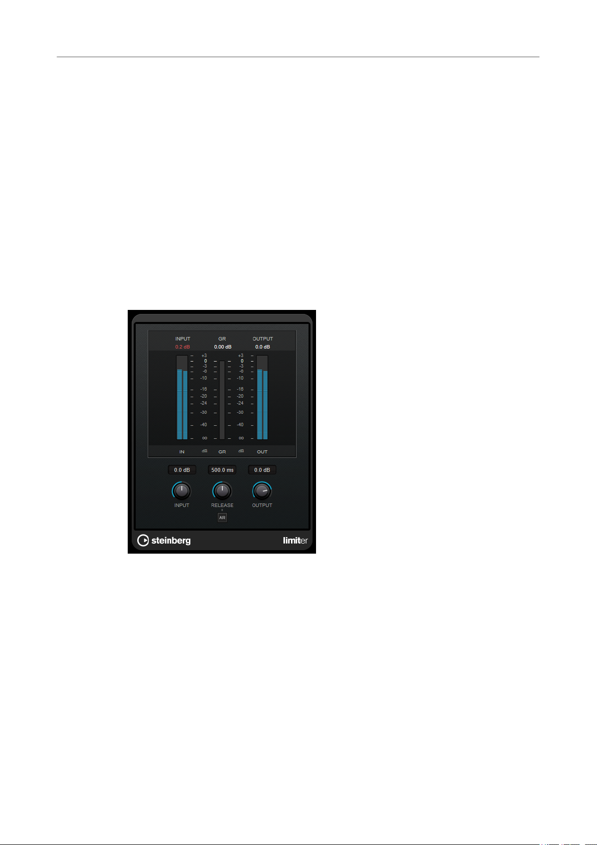
Limiter
Limiter is designed to ensure that the output level never exceeds a set output level, to avoid
clipping in following devices.
Applies parallel lters where the resonance depends on the amount of gain.
Applies parallel lters where the resonance is raised when boosting the gain and vice
versa.
Applies parallel lters where the resonance of the rst and last bands depends on
the sample rate.
Applies serial lters where a gain increase of one band lowers the gain in adjacent
bands.
Limiter can adjust and optimize the Release parameter automatically according to the audio
material, or it can be set manually. Limiter also features separate meters for the input, output
and the amount of limiting (middle meters).
Input (-24 to 24 dB)
Sets the input gain.
Release (0.1 to 1000 ms or Auto mode)
Sets the time after which the gain returns to its original level. If Auto Release is
activated, the plug-in automatically
material.
Output
Sets the maximum output level.
nds the best release setting for the audio
46
Page 47
Steinberg VST 3 Plug-ins
L/R to M/S, M/S to L/R
L/R to M/S, M/S to L/R
This plug-in allows you to convert a stereo signal into a M/S signal and vice versa.
The L/R to M/S tool converts a L/R signal that is divided into a left and a right signal into a M/S
signal that is divided into a mid signal (L+R) and side signals (L-R).
The M/S to L/R tool reconverts the M/S signal into a L/R signal.
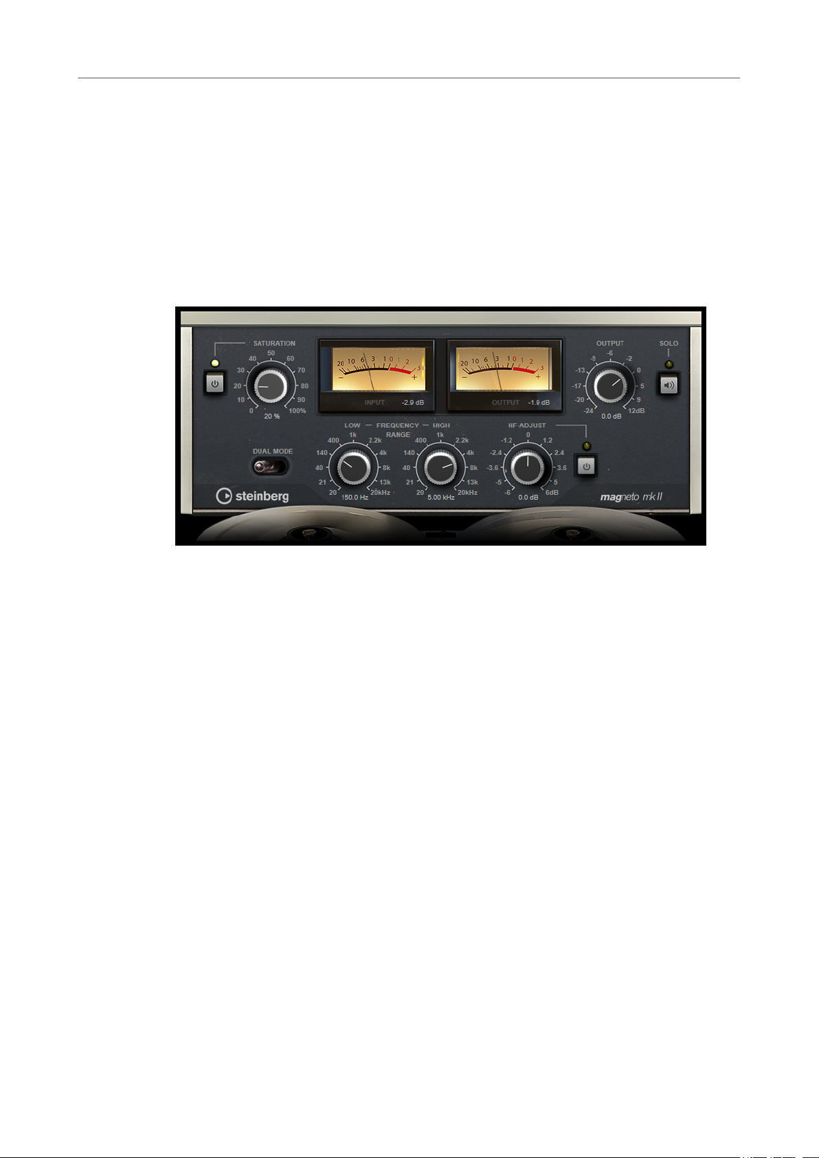
Magneto II
Magneto II simulates the saturation and compression of recording on analog tape machines.
Saturation
Determines the amount of saturation and the generation of overtones. This leads to
a small increase in input gain.
Saturation On/Off
Activates/Deactivates the saturation effect.
Dual Mode
Simulates the use of two machines.
Frequency Range Low/High
These parameters set the frequency range of the spectrum band to which the tape
effect is applied.
For example, to avoid the saturation of lower frequencies, set the Low value to 200
Hz or 300 Hz. To avoid the saturation of very high frequencies, set the
parameter to values below 10 kHz.
Solo
Allows you to hear only the set frequency range including the tape simulation effect.
This helps you to determine the appropriate frequency range.
HF-Adjust
Sets the amount of high frequency content of the saturated signal.
HF-Adjust On/Off
Activates/Deactivates the HF-Adjust lter.
High
47
Page 48

Steinberg VST 3 Plug-ins
Maximizer
Maximizer
Maximizer raises the loudness of audio material without the risk of clipping. The plug-in
provides two modes, Classic and Modern, that offer different algorithms and parameters.
Classic
Classic mode provides the classic algorithms from previous versions of this plug-in.
This mode is suited for all styles of music.
Modern
In Modern mode, the algorithm allows for more loudness than in Classic mode. This
mode is particularly suited for contemporary styles of music.
Modern mode also provides additional settings to control the release phase:
● Release sets the overall release time.
● Recover allows for a faster signal recovering at the beginning of the release
phase.
Optimize
Determines the loudness of the signal.
Mix
Sets the level balance between the dry signal and the wet signal.
Output
Sets the maximum output level.
Soft Clip
If this button is activated, Maximizer starts limiting or clipping the signal softly. At
the same time, harmonics are generated, adding a warm, tube-like characteristic to
the audio material.
48
Page 49
Steinberg VST 3 Plug-ins
Mix6to2
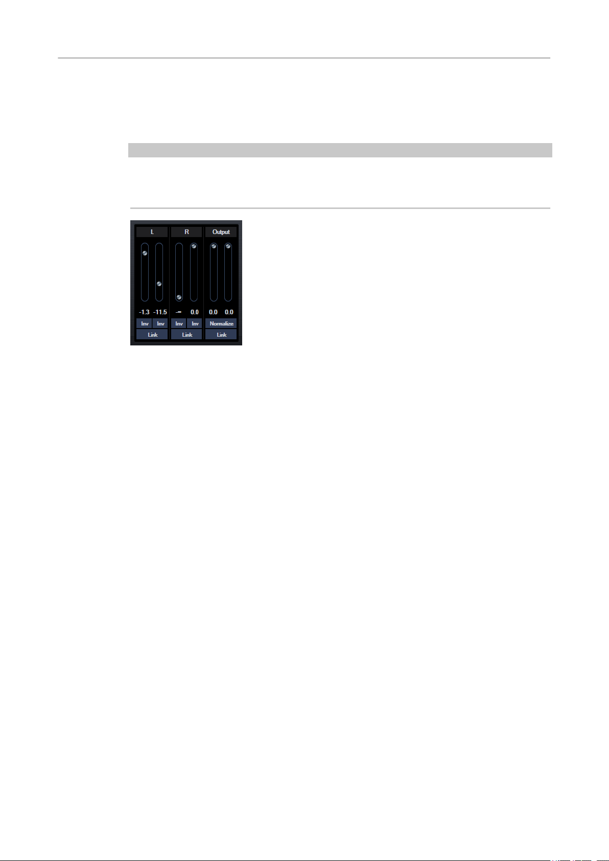
Mix6to2
Mix6to2 lets you quickly mix down your surround mix format to stereo. You can control the
levels of up to six surround channels and decide for each channel up to which level it is included
in the resulting mix.
NOTE
This plug-in does not simulate a surround mix or add any psycho-acoustical artifacts to the
resulting output – it is simply a mixer. The plug-in is only available in the
surround audio montage is active.
Master Section and if a
Surround Channels
Volume faders
Determine how much of the signal is included in the left and/or right channel of the
output bus.
Link
Links the volume faders of a surround channel.
Invert Phase
Inverts the phase of the corresponding surround bus channel.
Output Bus
Volume faders
Set the volume of the mixed output.
Link
Links the Output faders.
Normalize
If this option is activated, the mixed output is normalized. For example, the output
level is automatically adjusted so that the loudest signal is as loud as possible
without clipping.
49
Page 50

Steinberg VST 3 Plug-ins
Mix8to2
Mix8to2
Mix8to2 lets you quickly mix down your surround mix format to stereo. You can control the
levels of up to eight surround channels and decide for each channel up to which level it is
included in the resulting mix.
NOTE
This plug-in does not simulate a surround mix or add any psycho-acoustical artifacts to the
resulting output – it is simply a mixer. The plug-in is only available in the
8 channel audio montage is active.
Master Section and if a
Surround Channels
Volume faders
Determine how much of the signal is included in the left and/or right channel of the
output bus.
Link
Link the volume faders.
Invert Phase
Inverts the phase of the corresponding surround bus channel.
Output Bus
Volume faders
Set the volume of the mixed output.
Link
Links the Output faders.
Normalize
If this option is activated, the mixed output is normalized. For example, the output
level is automatically adjusted so that the loudest signal is as loud as possible
without clipping.
50
Page 51
Steinberg VST 3 Plug-ins
MonoDelay
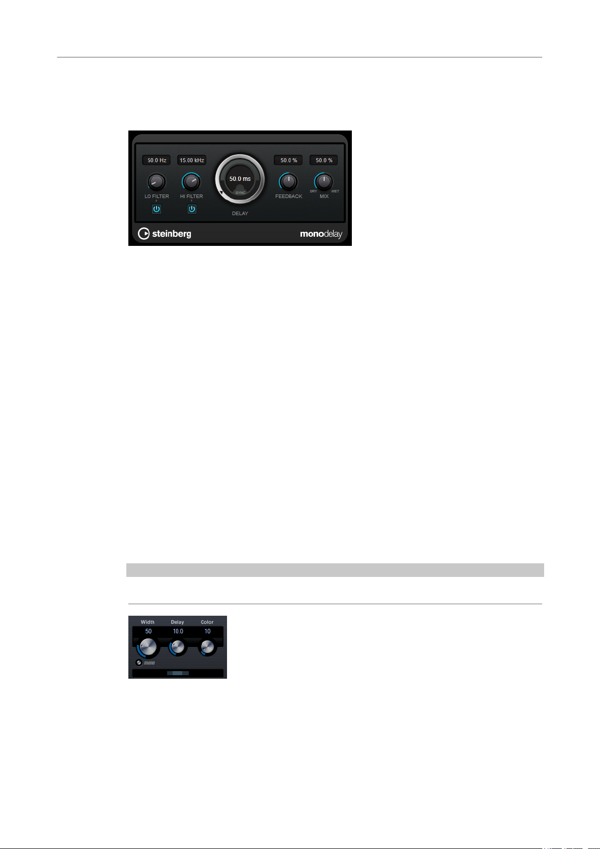
MonoDelay
This is a mono delay effect that can either be tempo-based or use freely specied delay time
settings.
Lo Filter
Hi Filter
Affects the feedback loop of the effect signal and allows you to roll off low
frequencies. The button below the knob activates/deactivates the lter.
Affects the feedback loop of the effect signal and allows you to roll off high
frequencies. The button below the knob activates/deactivates the lter.
Delay
If Tempo Sync is activated, this sets the base note value for the delay. If Tempo Sync
is deactivated, the delay time can be set freely in milliseconds.
Feedback
Sets the amount of the signal that is sent back into the delay input. The higher this
value, the higher the number of repeats.
Mix
Sets the level balance between the dry signal and the wet signal. If the effect is used
as a send effect, set this parameter to the maximum value, as you can control the
dry/effect balance with the send level.
MonoToStereo
MonoToStereo turns a mono signal into a pseudo-stereo signal. The plug-in can be used on a
mono le or a stereo le with equal channels.
NOTE
This plug-in works only on stereo tracks.
Delay
Increases the amount of differences between the left and right channels to further
increase the stereo effect.
51
Page 52
Steinberg VST 3 Plug-ins
MultibandCompressor
Width
Controls the width or depth of the stereo enhancement. Turn clockwise to increase
the enhancement.
Mono
Switches the output to mono, to check for possible unwanted coloring of the sound
which sometimes can occur when creating an
Color
Generates additional differences between the channels to increase the stereo
enhancement.
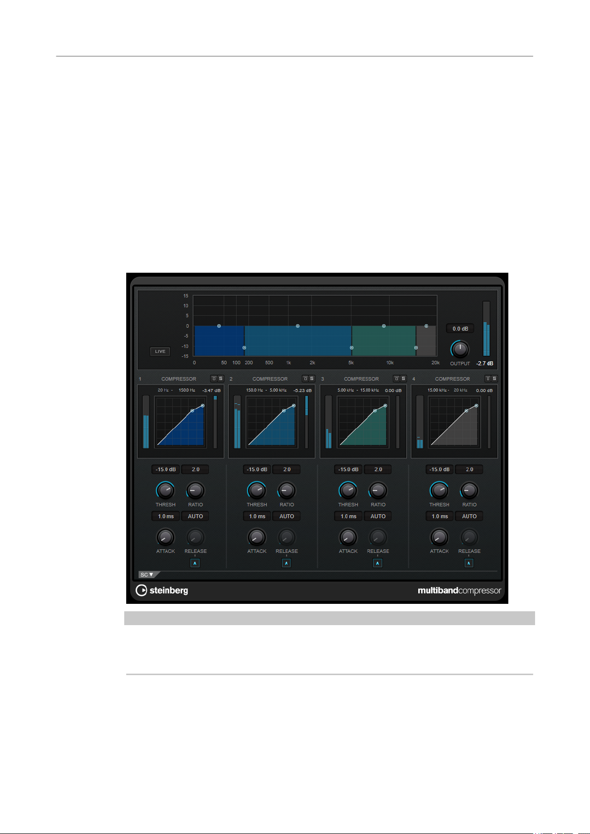
MultibandCompressor
MultibandCompressor allows a signal to be split into four frequency bands. You can specify the
level, bandwidth, and compressor characteristics for each band.
articial stereo image.
NOTE
To compensate for output gain loss that is caused by compression, MultibandCompressor uses
an automatic make-up gain. If side-chaining is activated for a frequency band in the side-chain
section, the automatic make-up gain is deactivated for this band.
Frequency Band Editor
The frequency band editor in the upper half of the panel is where you set the width of the
frequency bands as well as their level after compression. The vertical value scale to the left shows
the gain level of each frequency band. The horizontal scale shows the available frequency range.
52
Page 53

Steinberg VST 3 Plug-ins
MultibandCompressor
● To dene the frequency range of the different frequency bands, use the handles at the
● To attenuate or boost the gain of the frequency bands by ±15 dB after compression, use
Live
Bypassing Frequency Bands
Soloing Frequency Bands
Output (-24 to 24 dB)
Compressor Section
sides of each frequency band.
the handles at the top of each frequency band.
If this button is activated, the look-ahead feature of the effect is deactivated. Lookahead produces more accurate processing, but adds a specic amount of latency as
a trade-off. If Live mode is activated, there is no latency, which is better for live
processing.
To bypass each frequency band, activate the Bypass Band button in each section.
To solo a frequency band, activate the S button in each section. Only one band can
be soloed at a time.
Sets the output level.
You can specify the Threshold and Ratio by moving breakpoints or using the corresponding
knobs. The threshold is marked by the
diagonal.
Threshold (-60 to 0 dB)
Determines the level where the compressor kicks in. Only signal levels above the set
threshold are processed.
Ratio
Sets the amount of gain reduction applied to signals above the set threshold. A ratio
of 3:1 means that for every 3 dB the input level increases, the output level increases
by 1 dB.
Attack (0.1 to 100 ms)
Determines how fast the compressor responds to signals above the set threshold. If
the attack time is long, more of the early part of the signal passes through
unprocessed.
Release (10 to 1000 ms or Auto mode)
Sets the time after which the gain returns to its original level when the signal drops
below the threshold. If Auto Release is activated, the plug-in automatically nds the
best release setting for the audio material.
rst breakpoint where the line deviates from the straight
Side-Chain Section
To open the side-chain section, click the SC button at the bottom left of the plug-in window.
IMPORTANT
To be able to use the side-chain function for the bands, global side-chain must be activated for
the plug-in.
53
Page 54
Steinberg VST 3 Plug-ins
MultibandEnvelopeShaper
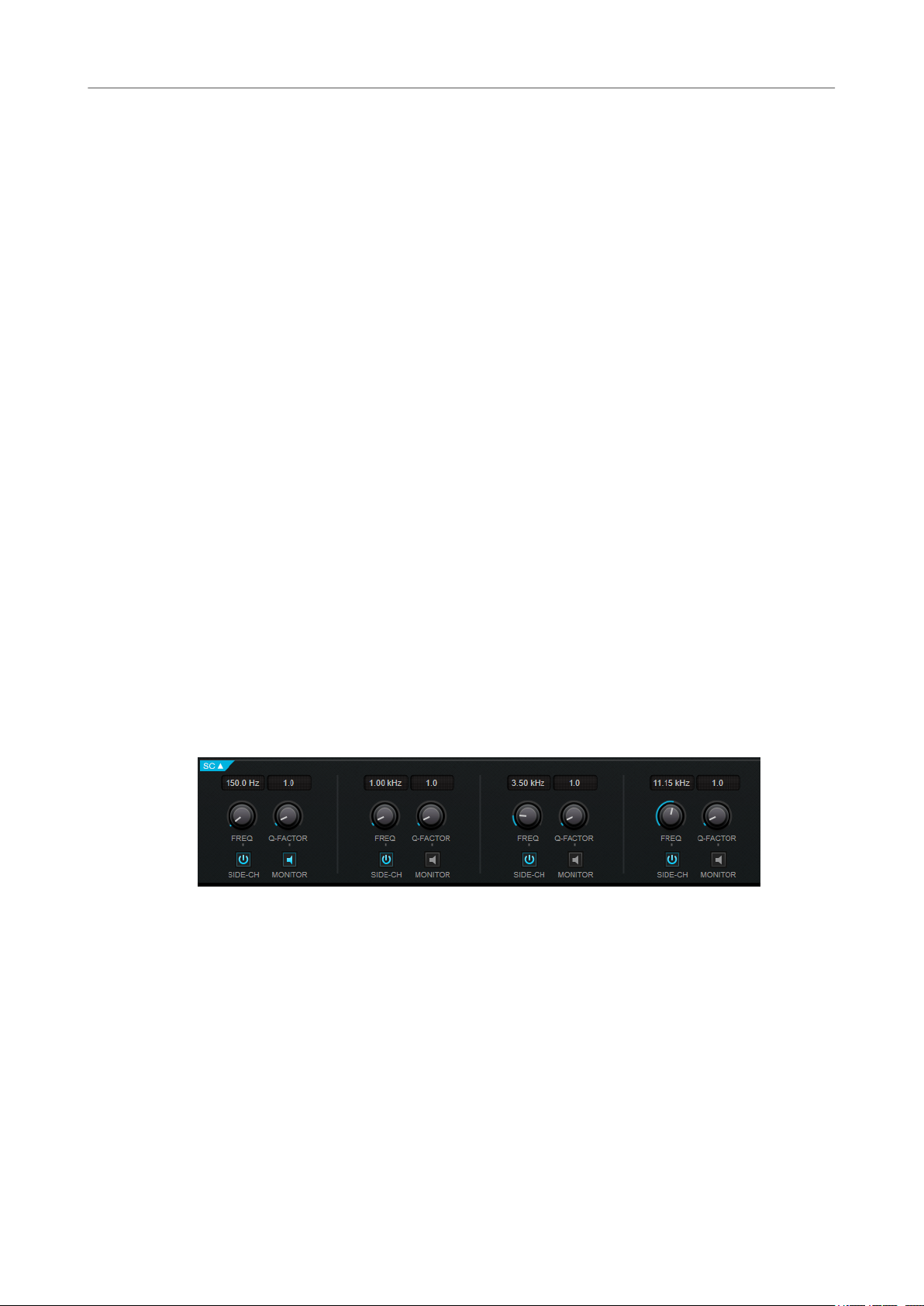
Frequency
If the Side-Chain button is activated, this sets the frequency of the side-chain lter.
Q-Factor
If the Side-Chain button is activated, this sets the resonance or width of the lter.
Side-Chain
Activates the internal side-chain lter. The side-chain signal can then be shaped
according to the
Monitor
Allows you to monitor the ltered signal.
lter parameter.
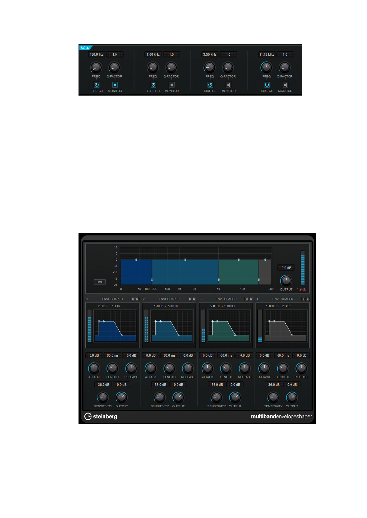
MultibandEnvelopeShaper
MultibandEnvelopeShaper allows a signal to be split into four frequency bands. You can
attenuate or boost the gain of the attack and release phase of audio material for each band.
Frequency Band Editor
The frequency band editor in the upper half of the panel is where you set the width of the
frequency bands as well as their level. The vertical value scale to the left shows the gain level of
each frequency band. The horizontal scale shows the available frequency range.
54
Page 55

Steinberg VST 3 Plug-ins
MultibandEnvelopeShaper
● To dene the frequency range of the different frequency bands, use the handles at the
sides of each frequency band.
● To attenuate or boost the gain of the frequency band, use the handles at the top of each
frequency band.
Live
If this button is activated, the look-ahead feature of the effect is deactivated. Lookahead produces more accurate processing, but adds a specic amount of latency as
a trade-off. If Live mode is activated, there is no latency, which is better for live
processing.
Bypassing Frequency Bands
To bypass each frequency band, activate the Bypass Band button in each section.
Soloing Frequency Bands
To solo a frequency band, activate the S button in each section. Only one band can
be soloed at a time.
Output (-24 to 24 dB)
Sets the output level.
Shaper Section
You can specify the Attack, Length, and Release by moving breakpoints or using the
corresponding knobs. Be careful with levels when boosting the gain. You can reduce the output
level to avoid clipping.
Attack (-20 to 20 dB)
Sets the gain of the attack phase of the signal.
Length (5 to 200 ms)
Sets the length of the attack phase.
Release
Sets the gain of the release phase of the signal.
Sensitivity (-40 to -10 dB)
Sets the sensitivity of the detection.
Output
Sets the output level.
55
Page 56
Steinberg VST 3 Plug-ins
MultibandExpander
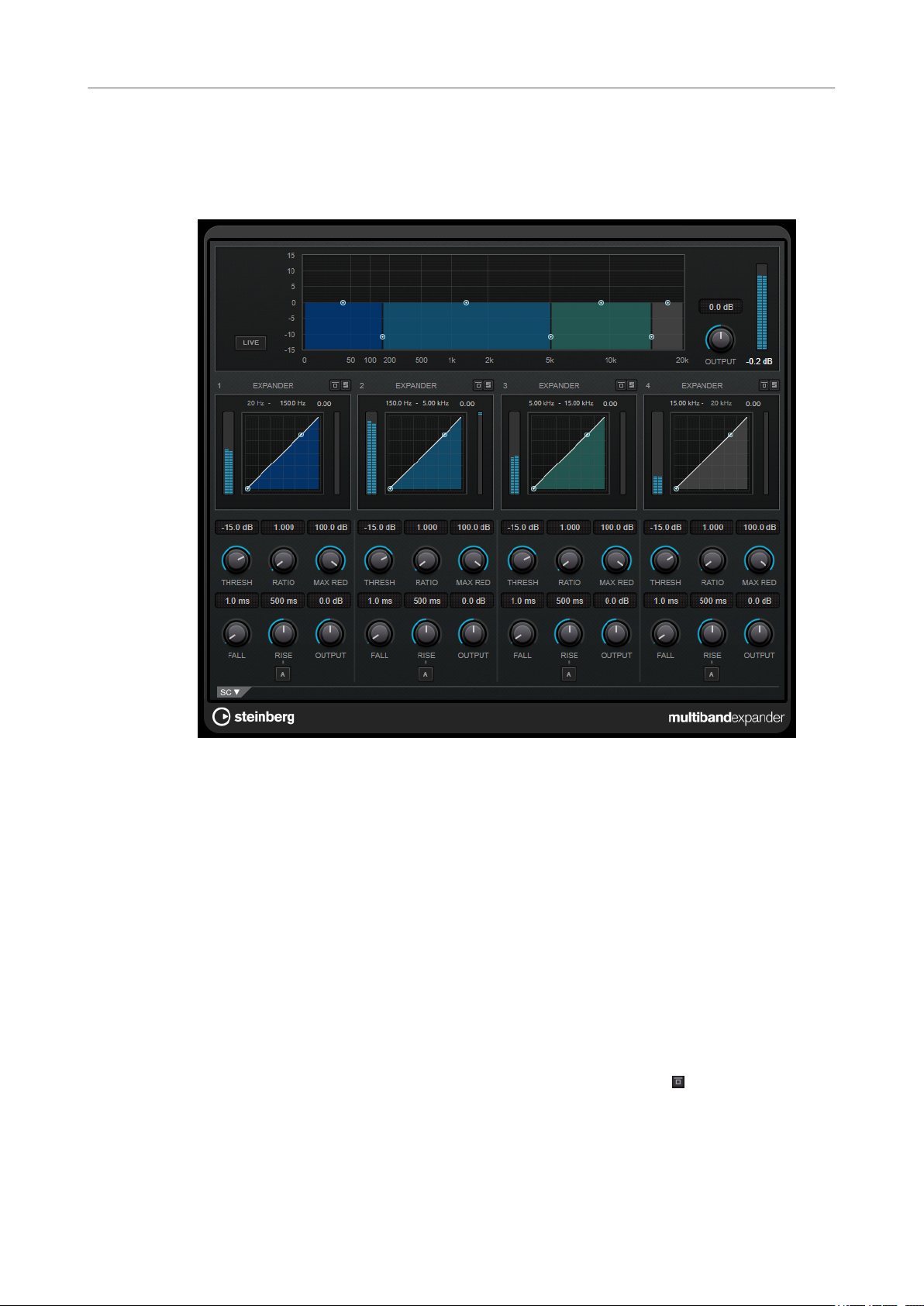
MultibandExpander
MultibandExpander allows a signal to be split into four frequency bands. You can reduce the
output level in relation to the input level for signals below the set threshold for each band. This is
useful if you want to enhance the dynamic range or reduce the noise in quiet passages.
Frequency Band Editor
The frequency band editor in the upper half of the panel is where you set the width of the
frequency bands as well as their level after expansion. The vertical value scale to the left shows
the gain level of each frequency band. The horizontal scale shows the available frequency range.
● To dene the frequency range of the different frequency bands, use the handles at the
sides.
● To attenuate or boost the gain of the frequency band after expansion, use the handles on
top of each frequency band.
Live
If this button is activated, the look-ahead feature of the effect is deactivated. Lookahead produces more accurate processing, but adds a
a trade-off. If Live mode is activated, there is no latency, which is better for live
processing.
Bypassing Frequency Bands
To bypass each frequency band, activate the Bypass Band button in each section.
Soloing Frequency Bands
To solo a frequency band, activate the S button in each section. Only one band can
be soloed at a time.
specic amount of latency as
56
Page 57
Steinberg VST 3 Plug-ins
MultibandExpander
Output (-24 to 24 dB)
Expander Section
You can specify the Threshold and Ratio by moving breakpoints or using the corresponding
knobs. The rst breakpoint from which the line deviates from the straight diagonal is the
threshold point.
Threshold
Ratio
Maximum Reduction
Fall (0.1 to 100 ms)
Sets the output level.
Determines the level where the expansion kicks in. Only signal levels below the set
threshold are processed.
Sets the amount of gain boost applied to signals below the threshold.
Sets the maximum amount by which the level is reduced when the signal falls below
the set threshold.
Determines how fast the expander responds to signals below the set threshold. If
the fall time is long, more of the early part of the signal passes through unprocessed.
Hold (0 to 2000 ms)
Sets the time the applied expansion affects the signal below the threshold.
Rise (10 to 1000 ms or Auto mode)
Sets the time after which the gain returns to its original level when the signal
exceeds the threshold. If the Auto Rise button is activated, the plug-in automatically
nds the best rise setting for the audio material.
Output
Sets the output level.
Side-Chain Section
Frequency
If the Side-Chain button is activated, this sets the frequency of the side-chain lter.
Q-Factor
If the Side-Chain button is activated, this sets the resonance or width of the lter.
Side-Chain
Activates the internal side-chain lter. The side-chain signal can then be shaped
according to the lter parameters. Side-chaining is useful for tailoring how the effect
operates.
Monitor
Allows you to monitor the ltered signal.
57
Page 58
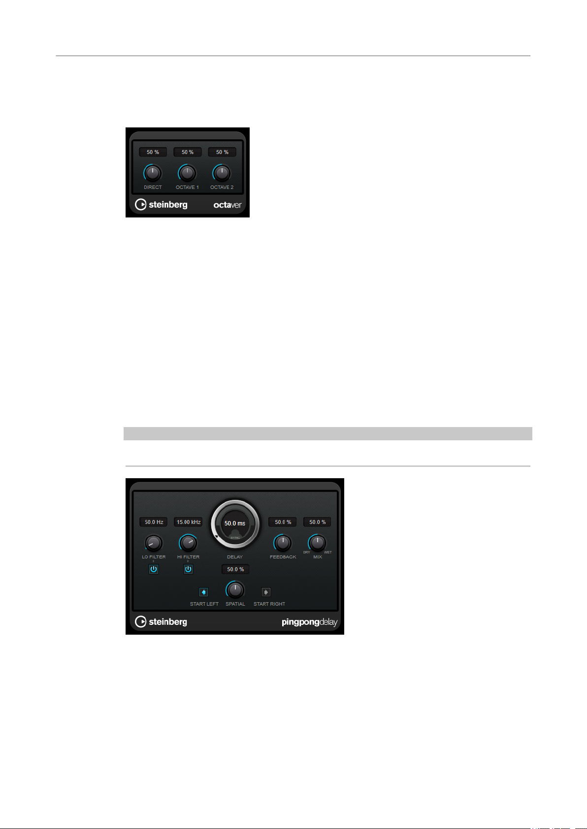
Steinberg VST 3 Plug-ins
Octaver
Octaver
This plug-in can generate two additional voices that track the pitch of the input signal one octave
and two octaves below the original pitch. Octaver is best used with monophonic signals.
Direct
Octave 1
Sets the level balance between the dry signal and the wet signal. A value of 0 means
that only the generated and transposed signal is heard. By raising this value, more of
the original signal is heard.
Adjusts the level of the generated signal one octave below the original pitch. A
setting of 0 means that the voice is muted.
Octave 2
Adjusts the level of the generated signal two octaves below the original pitch. A
setting of 0 means that the voice is muted.
PingPongDelay
This is a stereo delay effect that alternates each delay repeat between the left and right channels.
NOTE
This plug-in works only on stereo tracks.
Lo Filter
Affects the feedback loop of the effect signal and allows you to roll off low
frequencies. The button below the knob activates/deactivates the
Hi Filter
Affects the feedback loop of the effect signal and allows you to roll off high
frequencies. The button below the knob activates/deactivates the lter.
58
lter.
Page 59
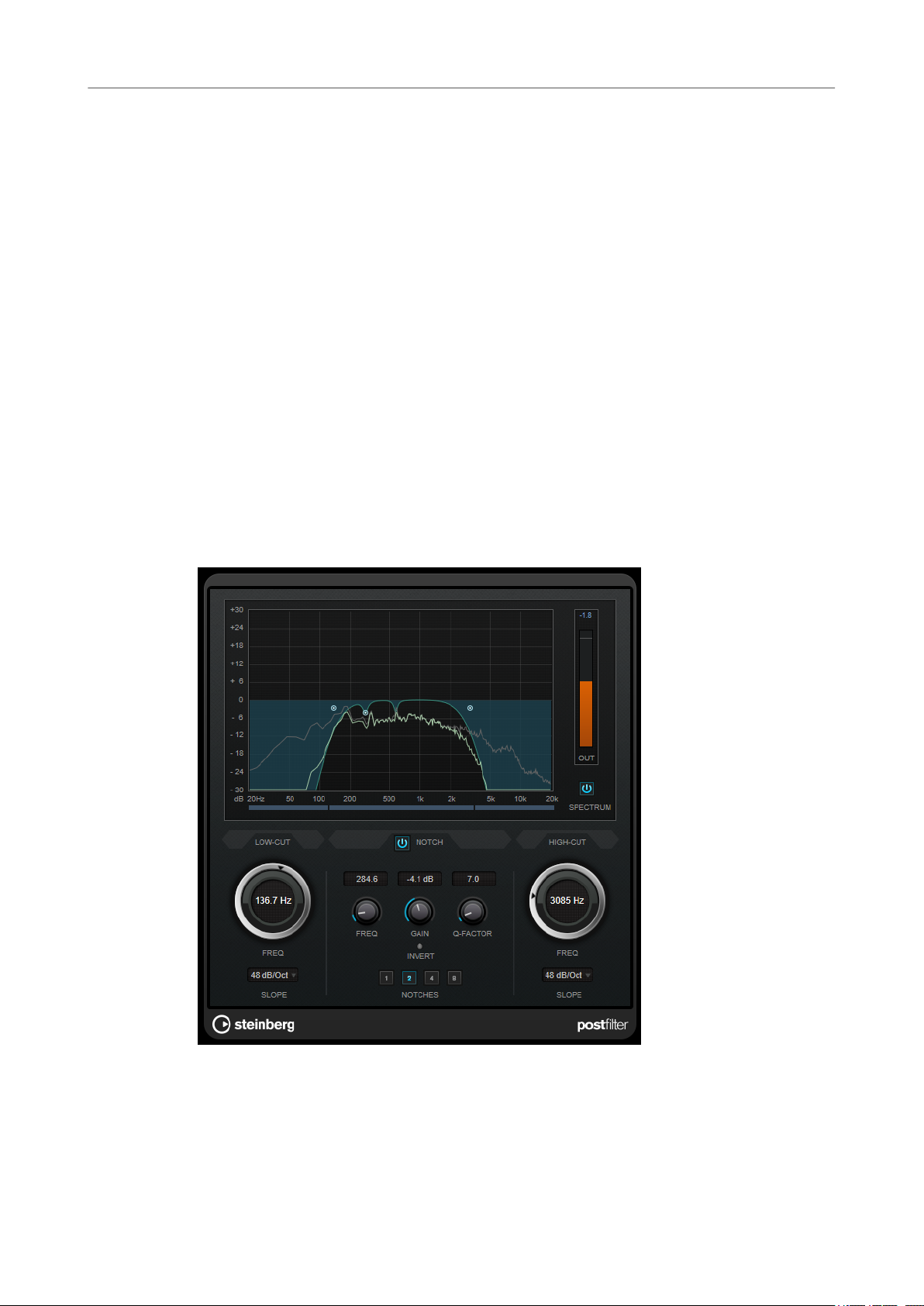
Steinberg VST 3 Plug-ins
PostFilter
Delay
Feedback
Mix
Spatial
Start Left/Start Right
PostFilter
If Tempo Sync is activated, this sets the base note value for the delay. If Tempo Sync
is deactivated, the delay time can be set freely in milliseconds.
Sets the amount of the signal that is sent back into the delay input. The higher this
value, the higher the number of repeats.
Sets the level balance between the dry signal and the wet signal. If the effect is used
as a send effect, set this parameter to the maximum value, as you can control the
dry/effect balance with the send level.
Sets the stereo width for the left/right repeats. Turn clockwise for a more
pronounced stereo ping-pong effect.
Determines whether the delay repeat starts on the left or the right channel.
This effect allows quick and easy ltering of unwanted frequencies, creating room for the
important sounds in your mix.
PostFilter combines a low-cut lter, a notch lter, and a high-cut lter. You can change the
settings by dragging the curve points in the graphical display, or by adjusting the controls below
the display section.
Graphical display
Visualizes the settings for all parameters.
59
Page 60

Steinberg VST 3 Plug-ins
PostFilter
Level meter
Low-Cut Freq (20 Hz to 1 kHz, or Off)
Low-Cut Slope
Low-Cut Preview
Shows the output level, giving you an indication of how the ltering affects the
overall level of the edited audio.
Allows you to eliminate low-frequency noise. The lter is inactive if the curve point is
located all the way to the left. You can set the frequency either in Hz or as a note
value. If you enter a note value, the frequency is automatically changed to Hz. For
example, a note value of A3 sets the frequency to 440 Hz. When you enter a note
value, you can also enter a cent offset. For example, enter A5 -23 or C4 +49.
NOTE
Ensure that you enter a space between the note and the cent offset. Only in this
case, the cent offsets are taken into account.
Allows you to choose a slope value for the low-cut lter.
Use this button between the Low-Cut controls and the graphical display to switch
the
lter to a complementary high-cut lter. This deactivates any other lters,
allowing you to listen only to the frequencies that you want to lter out.
Notch Freq
Sets the frequency of the notch lter. You can set the frequency either in Hz or as a
note value. If you enter a note value, the frequency is automatically changed to Hz.
For example, a note value of A3 sets the frequency to 440 Hz. When you enter a note
value, you can also enter a cent offset. For example, enter A5 -23 or C4 +49.
NOTE
Ensure that you enter a space between the note and the cent offset. Only in this
case, the cent offsets are taken into account.
Notch Gain
Adjusts the gain of the selected frequency. Use positive values to identify the
frequencies that you want to lter out.
Notch Gain Invert
This button inverts the gain value of the notch lter. Use this button to lter out
unwanted noise. When looking for the frequency to omit, it sometimes helps to
boost it
of the noise, you can use the Invert button to cancel it out.
Notch Q-Factor
Sets the width of the notch lter.
Notch Preview
Use this button between the notch lter controls and the graphical display to create
a band-pass lter with the peak lter's frequency and Q. This deactivates any other
lters, allowing you to listen only to the frequencies you want to lter out.
rst (set the notch lter to positive gain). After you have found the frequency
Notches buttons (1, 2, 4, 8)
These buttons add additional notch lters to lter out harmonics.
High-Cut Freq (3 Hz to 20 kHz, or Off)
This high-cut lter allows you to remove high-frequency noise. The lter is inactive if
the curve point is located all the way to the right. You can set the frequency either in
60
Page 61

Steinberg VST 3 Plug-ins
REVelation
High-Cut Slope
High-Cut Preview
REVelation
REVelation produces a high-quality algorithmic reverb with early reections and reverb tail.
Hz or as a note value. If you enter a note value, the frequency is automatically
changed to Hz. For example, a note value of A3 sets the frequency to 440 Hz. When
you enter a note value, you can also enter a cent offset. For example, enter A5 -23 or
C4 +49.
NOTE
Ensure that you enter a space between the note and the cent offset. Only in this
case, the cent offsets are taken into account.
Allows you to choose a slope value for the high-cut lter.
This button between the High-Cut controls and the graphical display allows you to
switch the lter to a complementary low-cut lter. This deactivates any other lters,
allowing you to listen only to the frequencies you want to lter out.
The early reections are responsible for the spatial impression in the rst milliseconds of the
reverb. For emulating different rooms, you can choose between different early reections
patterns and adjust their size. The reverb tail, or late reverberation, offers parameters for
controlling the room size and the reverb time. You can adjust the reverb time individually in 3
frequency bands.
Pre-Delay
Determines how much time passes before the reverb is applied. This allows you to
simulate larger rooms by increasing the time it takes for the rst reections to reach
the listener.
Early Reections
Here, you select an early reections pattern. The early reections pattern contains
the most important delays that deliver the key information for the spatial impression
of the room.
61
Page 62

Steinberg VST 3 Plug-ins
REVelation
ER/Tail Mix
Size
Low Cut
High Cut
Delay
Sets the level balance between the early reections and the reverb tail. At a setting of
50 %, early reections and tail have the same volume. Settings below 50 % raise the
reections and lower the tail, as a result the sound source moves towards the
early
front of the room. Settings above 50 % raise the tail and lower the early reections,
as a result the sound source moves towards the back of the room.
Adjusts the length of the early reections pattern. At a setting of 100 %, the pattern is
applied with its original length and the room sounds the most natural. At settings
below 100 %, the early
smaller.
Attenuates the low frequencies of the early reections. The higher this value, the less
low frequencies are present in the early
Attenuates the high frequencies of the early reections. The lower this value, the less
high frequencies the early reections will have.
Delays the onset of the reverb tail.
reections pattern is compressed and the room is perceived
reections.
Room Size
Controls the dimensions of the simulated room. At a setting of 100 %, the
dimensions correspond to a cathedral or a large concert hall. At a setting of 50 %, the
dimensions correspond to a medium-sized room or studio. Settings below 50 %
simulate the dimensions of small rooms or a booth.
Main Time
Controls the overall reverb time of the tail. The higher this value, the longer the
reverb tail will decay. At a setting of 100 %, the reverb time is innitely long. The
Main Time parameter also represents the mid band of the reverb tail.
High Time
Controls the reverb time for the high frequencies of the reverb tail. With positive
values, the decay time of the high frequencies is longer. With negative values, it is
shorter. Frequencies are affected depending on the High Freq parameter.
Low Time
Controls the reverb time for the low frequencies of the reverb tail. For positive
values, low frequencies decay longer and vice versa. Frequencies will be affected
depending on the Low Freq parameter.
High Freq
Sets the cross-over frequency between the mid and the high band of the reverb tail.
You can offset the reverb time for frequencies above this value from the main reverb
time with the High Time parameter.
Low Freq
Sets the cross-over frequency between the low and the mid band of the reverb tail.
The reverb time for frequencies below this value can be offset from the main reverb
time with the
Shape
Controls the attack of the reverb tail. At a setting of 0 %, the attack is more
immediate, which is a good setting for drums. The higher this value, the less
immediate the attack.
Low Time parameter.
62
Page 63
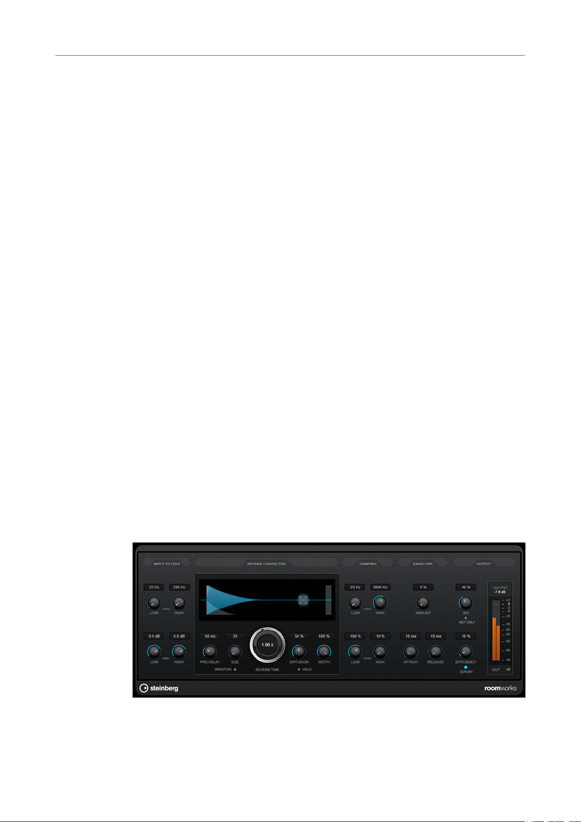
Steinberg VST 3 Plug-ins
RoomWorks
Density
High Cut
Width
Mix
Lock Mix Value
Adjusts the echo density of the reverb tail. At a setting of 100 %, single reections
from walls cannot be heard. The lower this value, the more single reections can be
heard.
Attenuates the high frequencies of the reverb tail. The lower this value, the less high
frequencies the reverb tail will have.
Controls the width of the stereo image. At a setting of 0 %, the output of the reverb is
mono, at 100 % it is stereo.
Sets the level balance between the dry signal and the wet signal. If the effect is used
as a send effect, set this parameter to the maximum value, as you can control the
dry/effect balance with the send level.
Activate this button (padlock symbol) next to the Mix parameter to lock the dry/wet
balance while browsing through the available presets.
Modulation
Modulation allows you to enrich the reverb tail through subtle pitch modulations.
Modulation Rate
Modulation Depth
Modulation Activate
RoomWorks
RoomWorks is a highly adjustable reverb plug-in for creating realistic room ambience and
reverb effects in stereo and surround formats. The CPU usage is adjustable to t the needs of
any system. From short room
reverberation.
Species the frequency of the pitch modulation.
Sets the intensity of the pitch modulation.
Activates/Deactivates the chorusing effect.
reections to cavern-sized reverb, this plug-in delivers high quality
63
Page 64

Steinberg VST 3 Plug-ins
RoomWorks
Input Filters
Low Frequency
High Frequency
Low Gain
High Gain
Reverb Character
Pre-Delay
Determines the frequency at which the low-shelving lter takes effect. Both the high
and low settings
Determines the frequency at which the high-shelving lter takes effect. Both the high
and low settings lter the input signal prior to reverb processing.
Sets the amount of boost or attenuation for the low-shelving lter.
Sets the amount of boost or attenuation for the high-shelving lter.
Determines how much time passes before the reverb is applied. This allows you to
simulate larger rooms by increasing the time it takes for the rst reections to reach
the listener.
lter the input signal prior to reverb processing.
Size
Alters the delay times of the early reections to simulate larger or smaller spaces.
Reverb Time
Allows you to set the reverb time in seconds.
Diffusion
Affects the character of the reverb tail. Higher values lead to more diffusion and a
smoother sound, while lower values lead to a clearer sound.
Width
Controls the width of the stereo image. At a setting of 0 %, the output of the reverb is
mono, at 100 % it is stereo.
Variation
Clicking this button generates a new version of the same reverb program using
altered reection patterns. This is helpful if some sounds are causing odd ringing or
undesirable results. Creating a new variation often solves these issues. There are
1000 possible variations.
Hold
Activating this button freezes the reverb buffer in an innite loop. You can create
some interesting pad sounds using this feature.
Damping
Low Frequency
Determines the frequency below which low-frequency damping occurs.
High Frequency
Determines the frequency above which high-frequency damping occurs.
Low Level
Affects the decay time of the low frequencies. Normal room reverb decays quicker in
the high- and low-frequency range than in the mid-range. Lowering the level
percentage causes low frequencies to decay quicker. Values above 100 % cause low
frequencies to decay more slowly than the mid-range frequencies.
64
Page 65

Steinberg VST 3 Plug-ins
RoomWorks
High Level
Envelope
Amount
Attack
Release
Affects the decay time of the high frequencies. Normal room reverb decays quicker
in the high- and low-frequency range than in the mid-range. Lowering the level
percentage causes high frequencies to decay quicker. Values above 100 % cause high
frequencies to decay more slowly than the mid-range frequencies.
Determines how much the envelope attack and release controls affect the reverb
itself. Lower values have a more subtle effect while higher values lead to a more
drastic sound.
The envelope settings in RoomWorks control how the reverb follows the dynamics of
the input signal in a fashion similar to a noise gate or downward expander. Attack
determines how long it takes for the reverb to reach full volume after a signal peak
(in milliseconds). This is similar to a pre-delay, but the reverb is ramping up instead
of starting all at once.
Determines how long after a signal peak the reverb can be heard before being cut
off, similar to a release time of a gate.
Output
Mix
Sets the level balance between the dry signal and the wet signal. If RoomWorks is
used as an insert effect for an FX channel, you most likely want to set this to 100 % or
use the wet only button.
Wet only
This button deactivates the Mix parameter, setting the effect to 100 % wet or
affected signal. This button should normally be activated if RoomWorks is used as a
send effect for an FX channel or a group channel.
Eciency
Determines how much processing power is used for RoomWorks. The lower the
value, the more CPU resources are used, and the higher the quality of the reverb.
Interesting effects can be created with very high
Export
Determines if during audio export RoomWorks uses the maximum CPU power for
the highest quality reverb. During export, you may want to keep a higher eciency
setting to achieve a specic effect. If you want the highest quality reverb during
export, make sure this button is activated.
Output meter
Shows the level of the output signal.
Eciency settings (>90 %).
65
Page 66

Steinberg VST 3 Plug-ins
RoomWorks SE
RoomWorks SE
RoomWorks SE is a smaller version of the RoomWorks plug-in. RoomWorks SE delivers high
quality reverberation, but has fewer parameters and is less CPU demanding than the full version.
Pre-Delay
Determines how much time passes before the reverb is applied. This allows you to
simulate larger rooms by increasing the time it takes for the rst reections to reach
the listener.
Reverb Time
Diffusion
Low Level
High Level
Mix
StereoDelay
Allows you to set the reverb time in seconds.
Affects the character of the reverb tail. Higher values lead to more diffusion and a
smoother sound, while lower values lead to a clearer sound.
Affects the decay time of the low frequencies. Normal room reverb decays quicker in
the high- and low-frequency range than in the mid-range. Lowering the level
percentage causes low frequencies to decay quicker. Values above 100 % cause low
frequencies to decay more slowly than the mid-range frequencies.
Affects the decay time of the high frequencies. Normal room reverb decays quicker
in the high- and low-frequency range than in the mid-range. Lowering the level
percentage causes high frequencies to decay quicker. Values above 100 % cause high
frequencies to decay more slowly than the mid-range frequencies.
Sets the level balance between the dry signal and the wet signal. When using
RoomWorks SE inserted in an FX channel, you most likely want to set this to 100 %.
StereoDelay has two independent delay lines with freely specied delay time settings.
NOTE
This plug-in works only on stereo tracks.
66
Page 67

Steinberg VST 3 Plug-ins
StereoEnhancer
Feedback
Delay
Set the number of repeats for each delay.
If Tempo Sync is activated, this sets the base note value for the delay. If Tempo Sync
is deactivated, the delay time can be set freely in milliseconds.
Mix
Sets the level balance between the dry signal and the wet signal. If the effect is used
as a send effect, set this parameter to the maximum value, as you can control the
dry/effect balance with the send level.
Lo Filter
Affects the feedback loop of the effect signal and allows you to roll off low
frequencies. The button below the knob activates/deactivates the lter.
Pan
Sets the stereo position.
Hi Filter
Affects the feedback loop of the effect signal and allows you to roll off high
frequencies. The button below the knob activates/deactivates the
StereoEnhancer
StereoEnhancer expands the stereo width of (stereo) audio material. It cannot be used with
mono les.
NOTE
This plug-in works only on stereo tracks.
lter.
67
Page 68
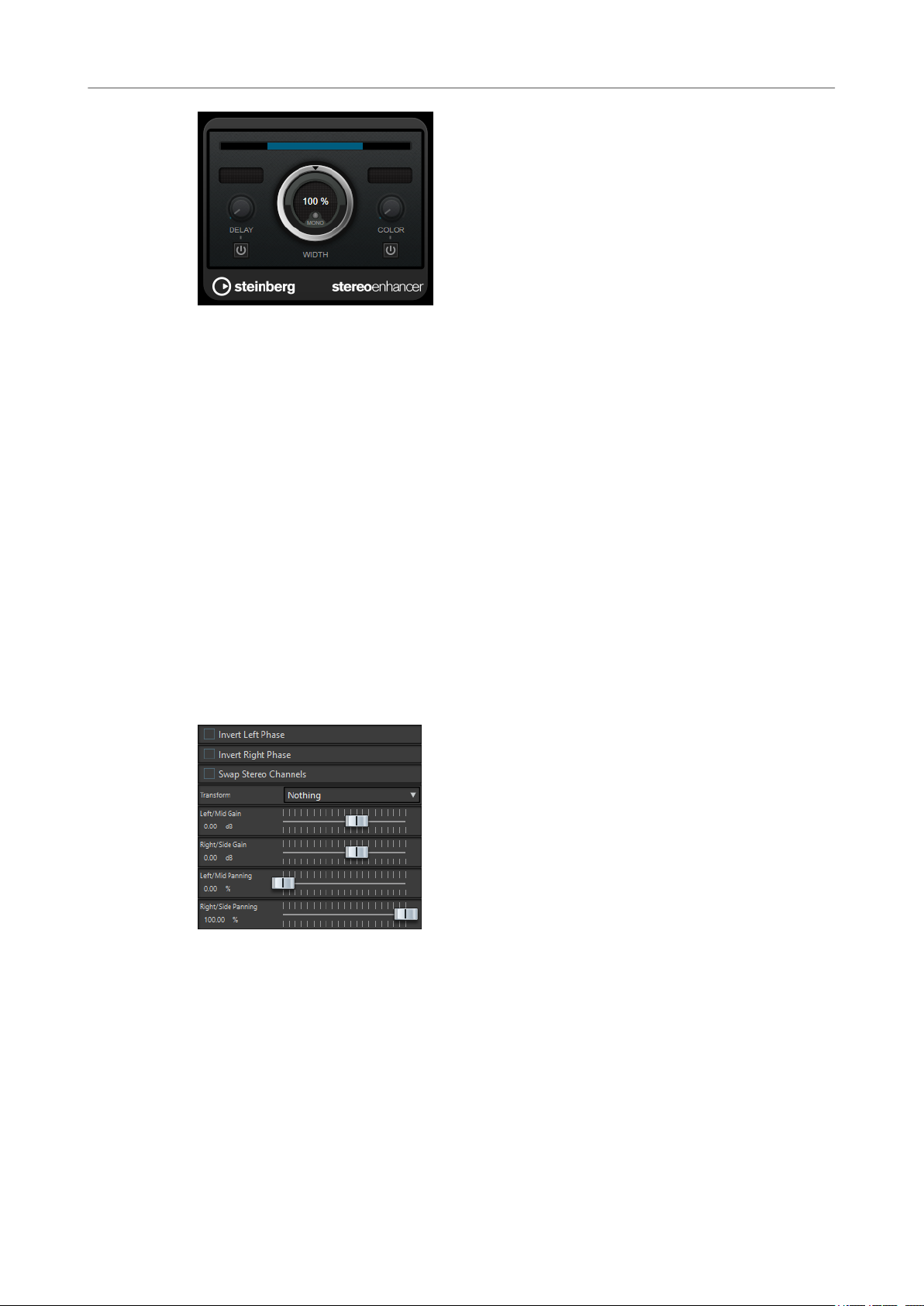
Steinberg VST 3 Plug-ins
Stereo Tools
Delay
Width
Mono
Increases the amount of differences between the left and right channels to further
increase the stereo effect.
Controls the width or depth of the stereo enhancement. Turn clockwise to increase
the enhancement.
Switches the output to mono, to check for possible unwanted coloring of the sound
which sometimes can occur when enhancing the stereo image.
Color
Stereo Tools
Stereo Tools allows you to pan or position both the left and right channels independently of one
another. You can use it for stereo les that you do not want to convert to mono or for xing a
problem with the stereo
Invert Left Phase/Invert Right Phase
Generates additional differences between the channels to increase the stereo
enhancement.
le, for example.
Inverts the polarity of an audio channel. You can use it for removing the center
information or for xing a channel that has been inverted, for example.
Swap Stereo Channels
Swaps the left and right channels.
Transform
Determines the conversion method:
● Nothing: No conversion of the signal.
● Left/Right -> Mid/Side: Converts a stereo signal into a mid/side signal.
68
Page 69
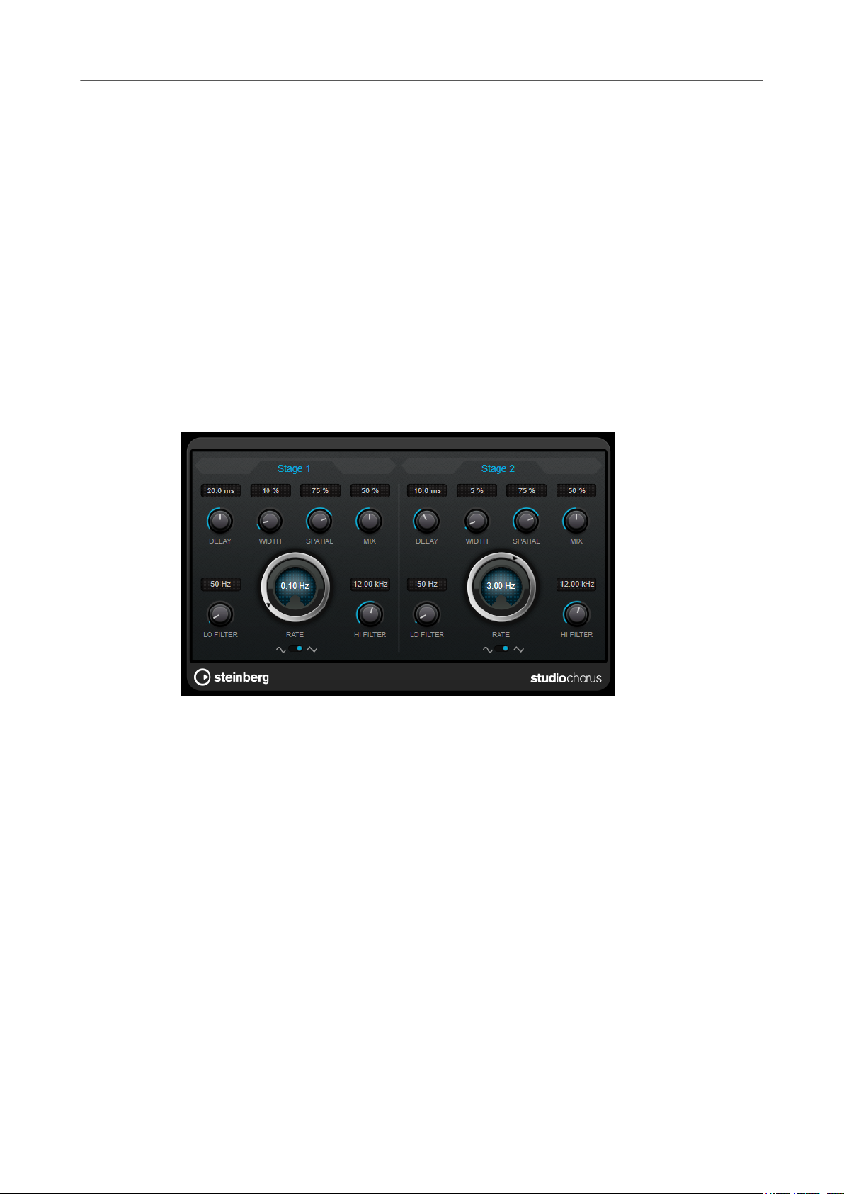
Steinberg VST 3 Plug-ins
StudioChorus
● Mid/Side -> Left/Right: Converts a mid/side signal into a stereo signal.
Left/Mid Gain (dB)
Sets the gain of the left stereo signal or the mid signal of the M/S signal.
Right/Side Gain (dB)
Sets the gain of the right stereo signal or of the side signals of the M/S signal.
Left/Mid Panning (%)
Pans the left stereo signal or the mid signal of the M/S signal.
Right/Side Panning (%)
Pans the right stereo signal or the side signals of the M/S signal.
StudioChorus
StudioChorus is a two-stage chorus effect that adds short delays to the signal and modulates
the pitch of the delayed signals to produce a doubling effect. The two separate stages of chorus
modulation are independent and are processed serially (cascaded).
Delay
Affects the frequency range of the modulation sweep by adjusting the initial delay
time.
Width
Sets the depth of the chorus effect. Higher settings produce a more pronounced
effect.
Spatial
Sets the stereo width of the effect. Turn clockwise for a wider stereo effect.
Mix
Sets the level balance between the dry signal and the wet signal. If the effect is used
as a send effect, set this parameter to the maximum value, as you can control the
dry/effect balance with the send level.
Rate
Allows you to set the sweep rate freely with the Rate knob.
Waveform Shape
Allows you to select the modulation waveform, altering the character of the chorus
sweep. A sine and a triangle waveform are available.
69
Page 70
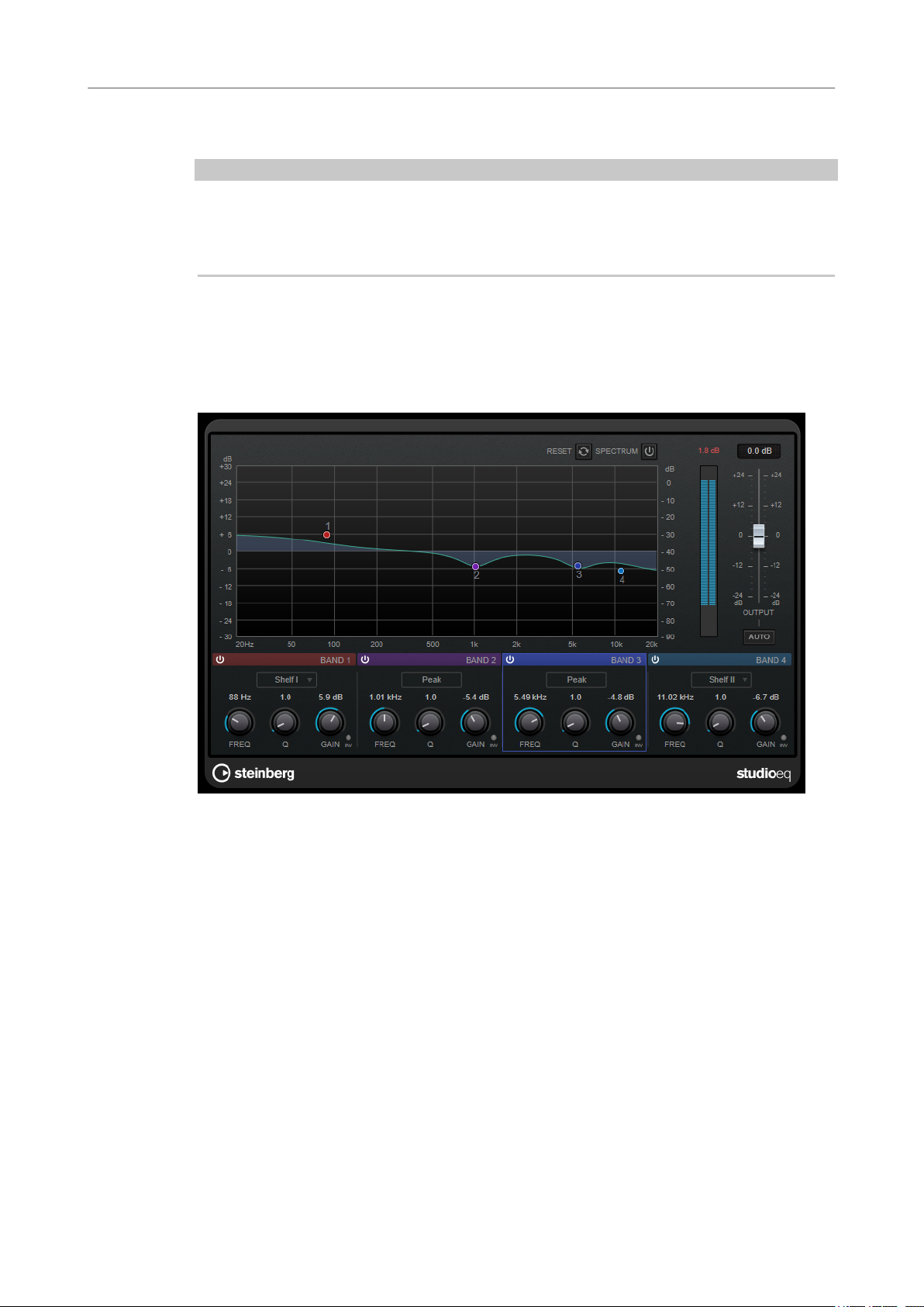
Steinberg VST 3 Plug-ins
StudioEQ
Lo Filter/Hi Filter
NOTE
If side-chaining is supported, the modulation can also be controlled from another signal source
via the side-chain input. If the side-chain signal exceeds the threshold, the modulation is
controlled by the side-chain signal’s envelope. For a description of how to set up side-chain
routing, see the
StudioEQ
Studio EQ is a high-quality 4-band parametric stereo equalizer. All four bands can act as fully
parametric peak lters. In addition, the low and high bands can act as either shelving lters
(three types) or as cut lters (low-pass/high-pass).
Allow you to roll off low and high frequencies of the effect signal.
Operation Manual.
Main Layout
Reset
Alt-click this button to reset all parameter values.
Show Input/Output Spectrum
Shows the spectrum before and after ltering.
Output
Adjusts the overall output level.
Auto Gain
If this button is activated, the gain is automatically adjusted, keeping the output level
nearly constant regardless of the EQ settings.
70
Page 71
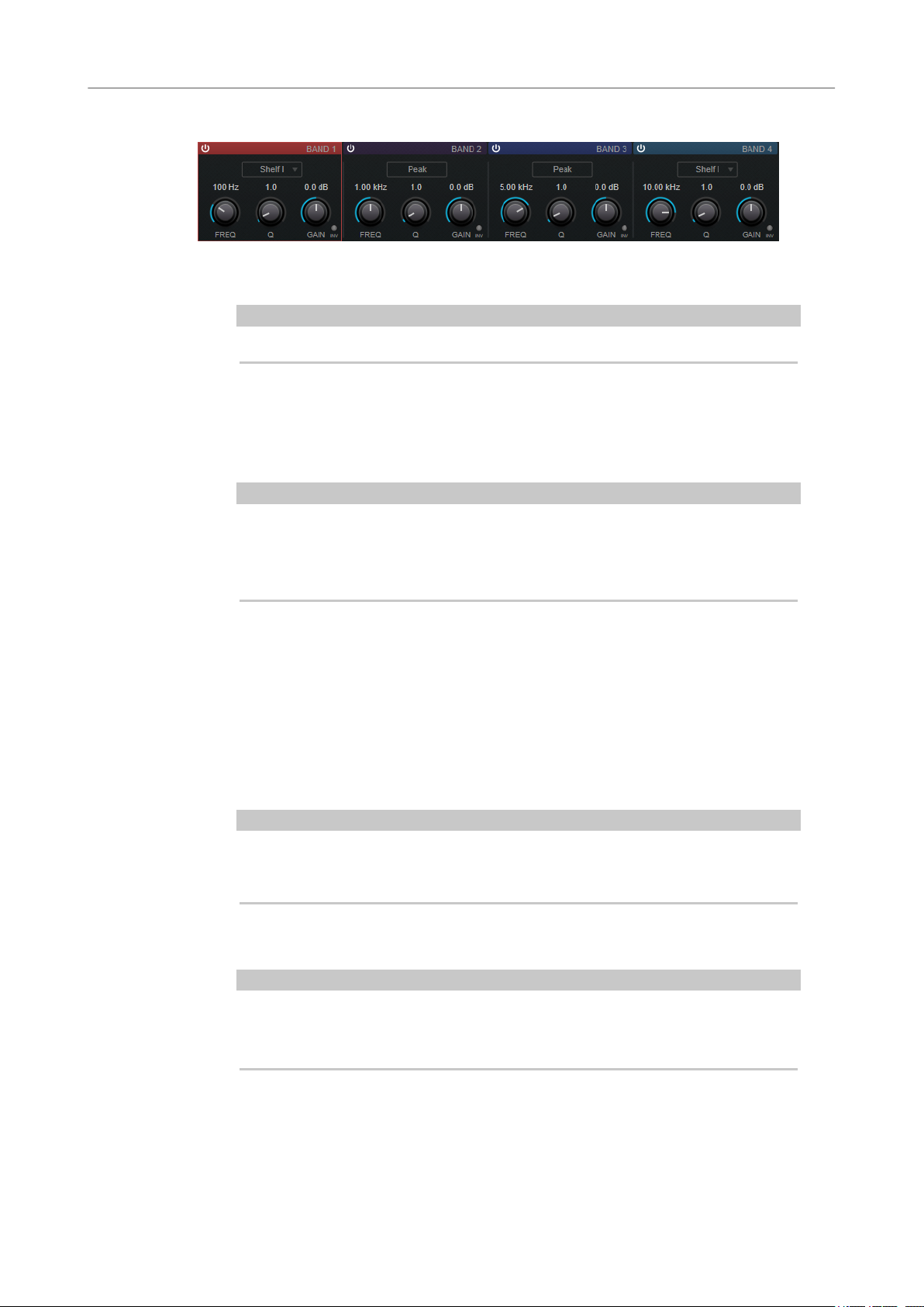
Steinberg VST 3 Plug-ins
StudioEQ
Band Settings
Activate/Deactivate Band
Freq
Activates/Deactivates the corresponding band.
NOTE
● If a band is deactivated, you can still modify its parameters.
Sets the frequency of the corresponding band. You can set the frequency either in Hz
or as a note value. If you enter a note value, the frequency is automatically changed
to Hz. For example, a note value of A3 sets the frequency to 440 Hz. When you enter
a note value, you can also enter a cent offset. For example, enter A5 -23 or C4 +49.
NOTE
● You can adjust the Freq parameter of a band in the graphical editor by Alt-
clicking the corresponding handle and moving the mouse left and right.
● Ensure that you enter a space between the note and the cent offset. Only in
this case, the cent offsets are taken into account.
Inv
Inverts the gain value of the lter. Use this button to lter out unwanted noise. When
looking for the frequency to omit, it sometimes helps to boost it in the
the lter to positive gain). After you have found the frequency of the noise, you can
use the Inv button to cancel it out.
Q
For Peak lters, this parameter controls the width of the band. For Shelf lters, it
adds a drop or a boost, depending on the gain setting of the band. For Cut lters, it
adds a resonance.
NOTE
● You can adjust the Q parameter of a band in the graphical editor by Shift-
clicking the corresponding handle and moving the mouse up and down.
Alternatively, you can point on the handle and turn the mouse wheel.
Gain
Sets the amount of attenuation/boost for the corresponding band.
rst place (set
NOTE
● You can adjust the Gain parameter of a band in the graphical editor by Ctrl/
Cmd-clicking the corresponding handle and moving the mouse up and down.
● This parameter is not available for Cut lters.
Filter type
For the low and high band, you can choose between three types of shelving lters, a
peak lter (band-pass), and a cut lter (low-pass/high-pass). If Cut mode is selected,
the Gain parameter is xed.
71
Page 72
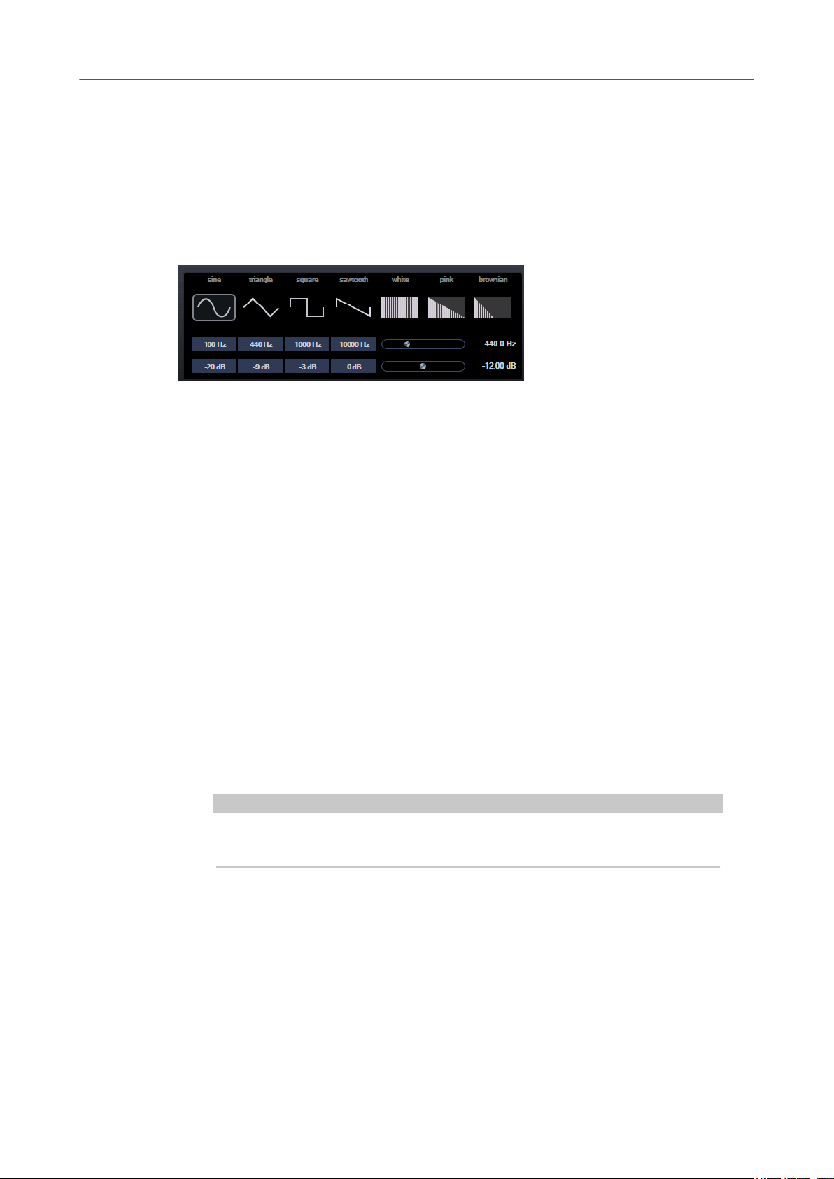
Steinberg VST 3 Plug-ins
TestGenerator
● Shelf I adds resonance in the opposite gain direction slightly above the set
● Shelf II adds resonance in the gain direction at the set frequency.
● Shelf III is a combination of Shelf I and II.
TestGenerator
This utility plug-in allows you to generate an audio signal, which can be recorded as an audio le.
The resulting le can then be used for a number of purposes:
● Testing the specications of audio equipment
● Measurements of various kinds, such as calibrating tape recorders
● Testing signal processing methods
● Educational purposes
frequency.
The TestGenerator is based on a waveform generator which can generate a number of basic
waveforms such as sine and saw as well as various types of noise. Furthermore, you can set the
frequency and amplitude of the generated signal. As soon as you add the TestGenerator as an
effect on an audio track and activate it, a signal is generated. You can then activate recording as
usual to record an audio
Waveforms and noise section
Allows you to set the basis for the signal generated by the waveform generator. You
can choose between four basic waveforms (sine, triangle, square, and sawtooth) and
three types of noise (white, pink, and brownian).
Frequency section
Allows you to set the frequency of the generated signal. You can set the frequency
either in Hz or as a note value. If you enter a note value, the frequency is
automatically changed to Hz. For example, a note value of A3 sets the frequency to
440 Hz. When you enter a note value, you can also enter a cent offset. For example,
enter A5 -23 or C4 +49.
NOTE
Ensure that you enter a space between the note and the cent offset. Only in this
case, the cent offsets are taken into account.
Gain section
Allows you to set the amplitude of the signal. The higher the value, the stronger the
signal. You can select one of the preset values, or use the slider to set a value
between -81 and 0 dB.
le according to the signal specications.
72
Page 73
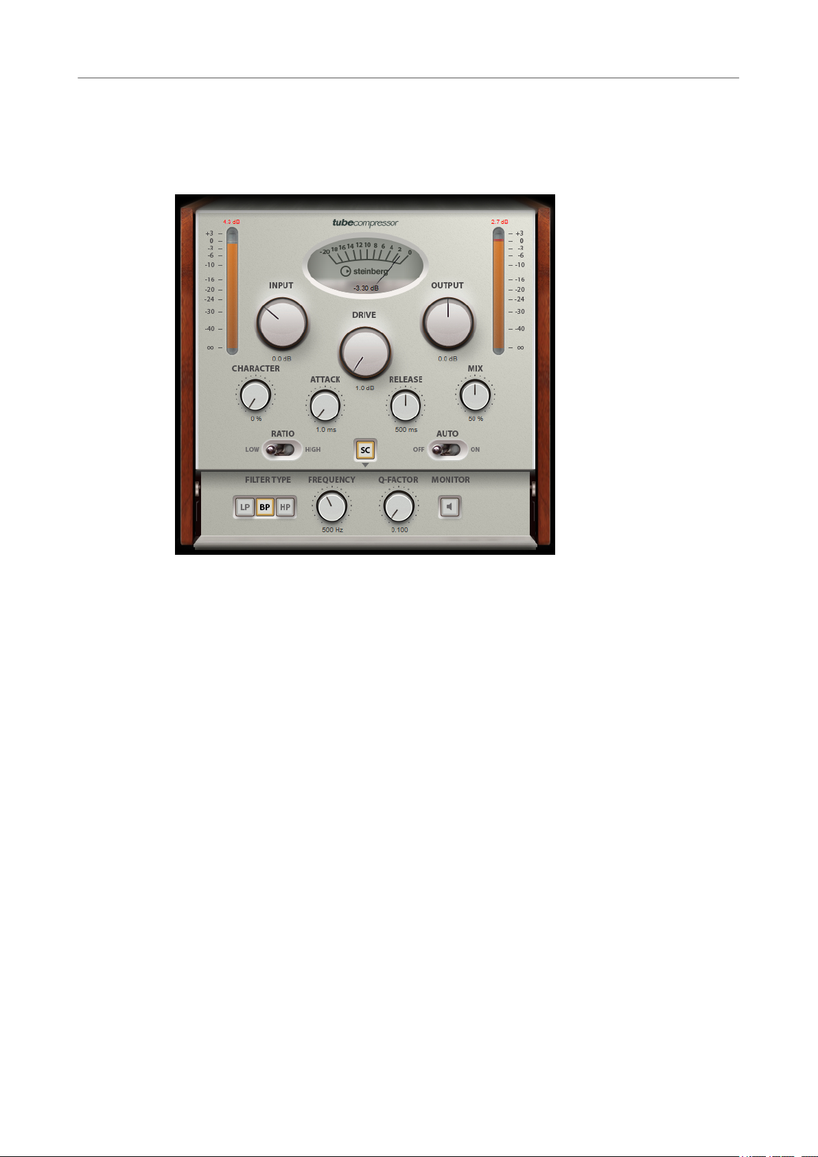
Steinberg VST 3 Plug-ins
Tube Compressor
Tube Compressor
This versatile compressor with integrated tube-simulation allows you to achieve smooth and
warm compression effects. The VU meter shows the amount of gain reduction. Tube
Compressor features an internal side-chain section that lets you lter the trigger signal.
Drive (1.0 to 6.0 dB)
Controls the amount of tube saturation.
Input
Determines the compression amount. The higher the input gain, the more
compression is applied.
Ratio
Toggles between a low and a high ratio value.
Output (-12 to 12 dB)
Sets the output gain.
Character
Keeps the bass tight and preserves its attacks by decreasing the tube saturation for
lower frequencies, and adds brilliance by creating harmonics for higher frequencies.
Attack (0.1 to 100 ms)
Determines how fast the compressor responds. If the attack time is long, more of the
initial part of the signal passes through unprocessed.
Release (10 to 1000 ms or Auto mode)
Sets the time after which the gain returns to its original level. If Auto Release is
activated, the plug-in automatically nds the best release setting for the audio
material.
Mix
Adjusts the mix between dry signal and wet signal, preserving the transients of the
input signal.
73
Page 74

Steinberg VST 3 Plug-ins
VintageCompressor
In/Out Meters
VU Meter
Side-Chain
Side-chain section
Filter Type (Low-Pass/Band-Pass/High-Pass)
Center (50 to 20000 Hz)
Q-Factor
Show the highest peaks of all available input and output channels.
Shows the amount of gain reduction.
Activates the internal side-chain lter. The input signal can then be shaped according
lter parameters. Internal side-chaining is useful for tailoring how the gate
to the
operates.
If Side-Chain is activated, these buttons allow you to set the lter type to low-pass,
band-pass, or high-pass.
If the Side-Chain button is activated, this sets the center frequency of the lter.
If the Side-Chain button is activated, this sets the resonance or width of the lter.
Monitor
Allows you to monitor the ltered signal.
VintageCompressor
VintageCompressor is modeled after vintage type compressors.
This compressor features separate controls for Input and Output gain, Attack, and Release. In
addition, there is a
dependent Auto feature for the Release parameter.
Input
Determines the compression amount. The higher the input gain, the more
compression is applied.
Punch mode which preserves the attack phase of the signal and a program-
Output (-48 to 24 dB)
Sets the output gain.
Attack (0.1 to 100 ms)
Determines how fast the compressor responds. If the attack time is long, more of the
initial part of the signal passes through unprocessed.
74
Page 75
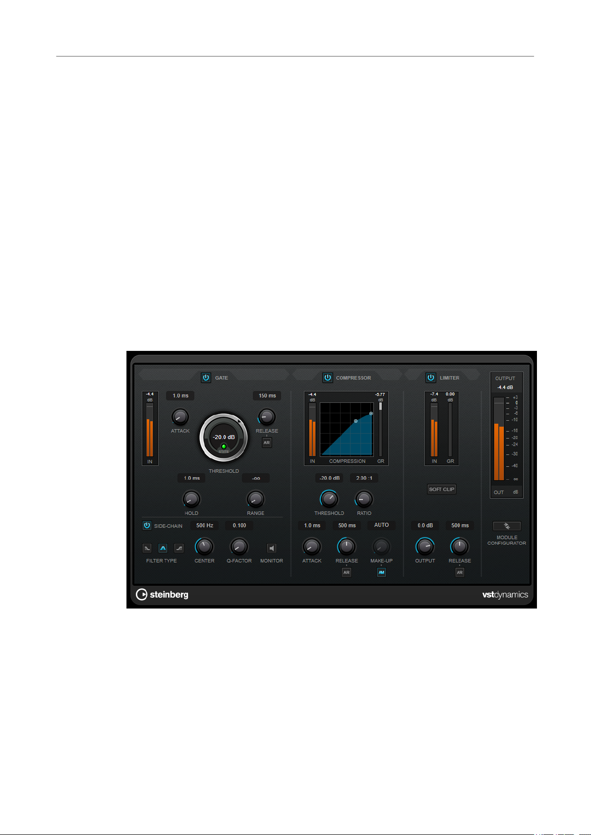
Steinberg VST 3 Plug-ins
VSTDynamics
Punch
If this is activated, the early attack phase of the signal is preserved, retaining the
original punch in the audio material, even with short Attack settings.
Release (10 to 1000 ms or Auto mode)
Sets the time after which the gain returns to its original level. If Auto Release is
activated, the plug-in automatically
material.
Mix
Adjusts the mix between dry signal and wet signal, preserving the transients of the
input signal.
VU Meter
Shows the amount of gain reduction.
In/Out Meters
Show the highest peaks of all available input and output channels.
VSTDynamics
nds the best release setting for the audio
VSTDynamics is an advanced dynamics processor. It combines three separate effects: Gate,
Compressor, and Limiter, covering a variety of dynamic processing functions.
Gate
Gating, or noise gating, is a method of dynamic processing that silences audio signals below a
set threshold. As soon as the signal level exceeds the threshold, the gate opens to let the signal
through. The gate trigger input can also be ltered using an internal side-chain signal.
The following parameters are available:
Input meter
Shows the level of the input signal.
75
Page 76

Steinberg VST 3 Plug-ins
VSTDynamics
Attack (0.1 to 100 ms)
Threshold
State LED
Release (10 to 1000 ms or Auto mode)
Hold (0 to 2000 ms)
Determines how fast the compressor responds to signals above the set threshold. If
the attack time is long, more of the early part of the signal passes through
unprocessed.
Determines the level at which the gate is activated. Signal levels above the set
threshold trigger the gate to open, and signal levels below the set threshold close
the gate.
Indicates whether the gate is open (LED lights up in green), closed (LED lights up in
red), or in an intermediate state (LED lights up in yellow).
Sets the time after which the gate closes after the set Hold time. If Auto Release is
activated, the plug-in automatically nds the best release setting for the audio
material.
Determines how long the gate remains open after the signal drops below the
threshold level.
Range
Adjusts the attenuation of the gate when it is shut. If Range is set to minus innite
, the gate is completely shut. The higher the value, the higher the level of the
signal that passes through the shut gate.
Side-Chain
Activates the internal side-chain lter. The input signal can then be shaped according
to the lter parameters. Internal side-chaining is useful for tailoring how the gate
operates.
Filter Type (Low-Pass/Band-Pass/High-Pass)
If Side-Chain is activated, these buttons allow you to set the lter type to low-pass,
band-pass, or high-pass.
Center (50 to 20000 Hz)
If the Side-Chain button is activated, this sets the center frequency of the lter.
Q-Factor
If the Side-Chain button is activated, this sets the resonance or width of the lter.
Monitor
Allows you to monitor the ltered signal.
Compressor
Compressor reduces the dynamic range of the audio, making softer sounds louder or louder
sounds softer, or both. It features a separate display that graphically illustrates the compressor
curve shaped according to your settings.
Input meter
Shows the level of the input signal.
Graphical display
Visualizes the settings for Threshold and Ratio and allows you to adjust them by
dragging the handles.
76
Page 77

Steinberg VST 3 Plug-ins
VSTDynamics
Gain Reduction meter
Threshold (-60 to 0 dB)
Ratio
Make-Up (0 to 24 dB or Auto mode)
Attack (0.1 to 100 ms)
Release (10 to 1000 ms or Auto mode)
Shows the amount of gain reduction.
Determines the level where the compressor kicks in. Only signal levels above the set
threshold are processed.
Sets the amount of gain reduction applied to signals above the set threshold. A ratio
of 3:1 means that for every 3 dB the input level increases, the output level increases
by 1 dB.
Compensates for output gain loss caused by compression. If Auto Make-Up Gain is
activated, the output is automatically adjusted for gain loss.
Determines how fast the compressor responds to signals above the set threshold. If
the attack time is long, more of the early part of the signal (attack) passes through
unprocessed.
Sets the time after which the gain returns to its original level when the signal drops
below the threshold. If Auto Release is activated, the plug-in automatically nds the
best release setting for the audio material.
Limiter
A limiter ensures that the output level never exceeds a set threshold to avoid clipping in effects
following in the chain. Conventional limiters usually require a very accurate setup of the attack
and release parameters to prevent the output level from going beyond the set threshold level.
Limiter adjusts and optimizes these parameters automatically according to the audio material.
Input meter
Shows the level of the input signal.
Gain Reduction meter
Shows the amount of gain reduction.
Soft Clip
If this button is activated, the signal is limited when the signal level exceeds -6 dB. At
the same time, harmonics are generated, adding a warm, tube-like characteristic to
the audio material.
Output
Sets the maximum output level.
Release (10 to 1000 ms or Auto mode)
Sets the time after which the gain returns to its original level. If Auto Release is
activated, the plug-in automatically nds the best release setting for the audio
material.
Output section
Output meter
Shows the level of the output signal.
Module Congurator
Changes the signal ow through the three effects. Changing the order of the effects
can produce different results, and the available routing congurations allow you to
77
Page 78

Steinberg VST 3 Plug-ins
VSTDynamics
● G-C-L (Gate-Compressor-Limiter)
● C-L-G (Compressor-Limiter-Gate)
● C-G-L (Compressor-Gate-Limiter)
quickly compare what works best for a given situation. Click Module Congurator to
toggle between the following routing congurations:
78
Page 79

Legacy Plug-ins
Under Windows, a set of plug-ins is provided for compatibility with audio projects that referenced
these effects when using earlier versions of WaveLab. An audio montage which referenced these
plug-ins would otherwise require cumbersome user intervention to open, for example.
Their use with new audio projects is not recommended and they are not documented.
79
Page 80

Dithering Plug-ins
Dithering plug-ins add small quantities of noise to a signal to reduce the audibility of low level
distortion in a digital recording. A small amount of random noise is added to the analog signal
before the sampling stage, reducing the effect of quantization errors.
Internal Dithering
This is a WaveLab-specic plug-in that provides a simple way of adding a small amount of noise
to the rendered signal to improve the apparent signal-to-noise ratio of the output.
The following parameters are available when selecting Internal Dithering.
Noise Type
Sets the noise type for adding to the signal.
● In No Noise mode, no dithering is applied.
● The Noise Type 1 mode is the most all-round method.
● The Noise Type 2 mode emphasizes higher frequencies more than Noise
Type 1.
Noise Shaping
Increases the apparent signal to noise ratio by altering the spectrum of the low-level
audio signal which results from lowering the number of bits. The higher the number
you select here, the more the noise is moved out of the ear’s mid-range.
Bit Resolution
Allows you to specify the intended bit resolution for the nal audio, after dithering,
regardless of whether you want to render the settings or play back in real-time.
Dithering changes the sample resolution, but not the sample size. For example,
when dithering 24 bit to 16 bit, the le will still be 24 bit in size, although only 16 bits
of information will have signicance. When rendering to a 16-bit le, specify the le
resolution to avoid wasting space.
MBIT+™ Dithering
This plug-in allows you to convert and dither to 24, 20, 16, 12, or 8 bits. This is useful for
mastering a track for a CD (16-bit) from a 24-bit source, for example.
The MBIT+™ dither algorithm reduces quantization distortion with minimal perceived noise and
produces smooth and quiet conversions.
80
Page 81

Dithering Plug-ins
MBIT+™ Dithering
Bit Quantization
Sets the bit depth to which you are dithering. MBIT+™ produces 32-bit oating-point
output, but all low-order bits will be zero and should be truncated.
Type
Sets the type of dithering. MBIT+™ contains two traditional dithering types and a
proprietary MBIT+™ dithering type.
● Type 1 is a traditional dither based on a rectangular probability distribution
function (PDF).
● Type 2 is a traditional dither based on a triangular PDF.
● MBIT+™ offers superior results when used with all types of source material.
Dither Amount
When using MBIT+™ dither, this controls the amount of dithering. The None and
Low settings can leave some non-linear quantization distortion or dither noise
modulation, while higher settings completely eliminate the non-linear distortion at
the expense of a slightly increased noise
cases.
When using Type 1 or Type 2 dither, this controls the number of bits used to perform
dithering. In most cases, 1 bit is suce, but over-dithering with 2 bits can be useful in
same cases.
Noise Shaping
When using MBIT+™ dither, this controls the amount of noise shaping. The choices
range from no noise shaping to very aggressive noise shaping, providing
approximately 14 dB of audible noise suppression, at the expense of a higher noise
oor.
When using Type 1 or Type 2 dither, this controls the noise shaping. Dithering noise
can be shaped in order to make it less audible. Simple noise shaping performs
simple high-pass ltering on the noise. Clear noise shaping aggressively moves the
noise toward the Nyquist frequency.
noise away from audible bands, and Psych 9 is a 9th-order lter with similar
characteristics.
Auto-Blanking
If this option is activated, MBIT+™ mutes dither output when the input is completely
silent for at least 0.7 seconds.
oor. The Normal setting is suce for most
Psych 5 is a 5th-order lter designed to move
Minimize Peaks
If this option is activated, spurious peaks in the noise-shaped dither are suppressed.
Harmonics Suppression
If this option is activated, the truncation rules are slightly altered, moving the
harmonic quantization distortion away from overtones of audible frequencies. This
option does not create any random dithering noise
truncation, but with better tonal quality in the resulting signal. This option is
81
oor. Instead it works more like
Page 82

Dithering Plug-ins
UV22HR
UV22HR
applicable only in the modes without dithering noise and without aggressive noise
shaping.
Copyright © 2013 iZotope, Inc. All rights reserved.
UV22HR is an advanced version of Apogee's renowned UV22 dithering algorithm, capable of
dithering to 8, 16, 20, or 24 bits.
8, 16, 20, 24 bit
These buttons allow you to select the intended bit resolution for the nal audio. As
when using the internal dithering, it is important to set this to the correct resolution.
Hi
Applies a normal dither gain.
Lo
Applies a lower level of dither noise.
Auto black
If this option is activated, the dither noise is gated during silent passages.
82
Page 83
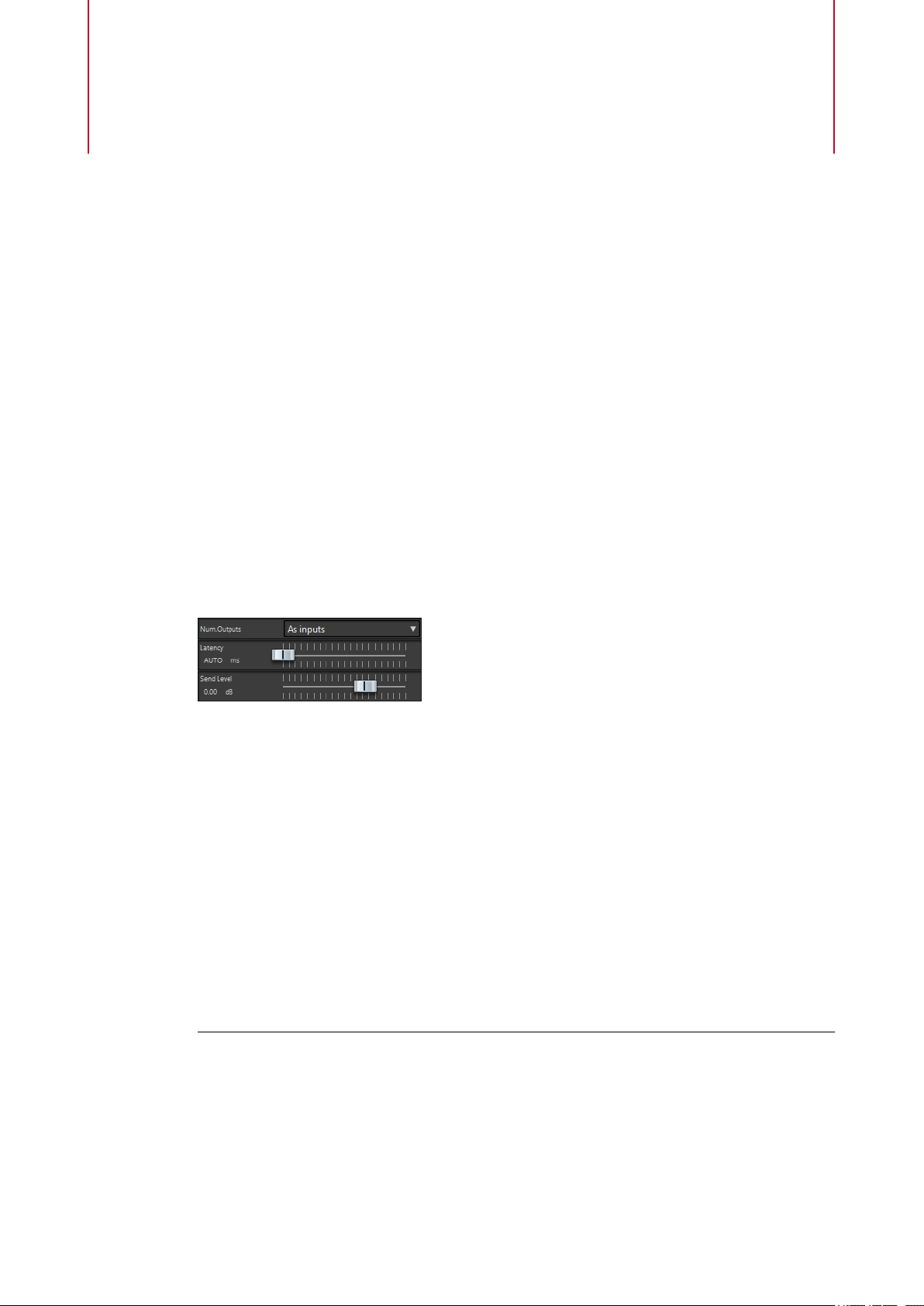
ASIO Plug-ins
External Gear
This Master Section plug-in allows you to process audio les using external hardware
processors. One or more ASIO outputs are used to send the audio signal to your processor, and
corresponding ASIO inputs are used to return the signal from the external processor.
By default, this plug-in is located in the ASIO submenu of the Master Section effects. An ASIO
driver must be used, and only one instance of this plug-in is allowed in the Master Section plugin chain.
External Gear Plug-in
In the Effects pane of the Master Section window, select the External Gear plug-in from the
ASIO submenu.
Num. Outputs
Here you can set the number of outputs to use. Normally this is the same as the
number of inputs (the
conguration in which case you set this parameter to 2 with the slider.
Latency
External gear may introduce latency. WaveLab can automatically compensate for this
if you select
compensation yourself (in milliseconds). The latency introduced by the ASIO driver is
automatically taken into account by WaveLab.
Send Level
Allows you to adjust the send level. This should normally be set to 0 dB. If necessary,
adjust the input level on the external effect.
Using External Gear
PROCEDURE
1. Select File > Preferences > VST Audio Connections.
2. Set the Audio Device to ASIO.
3. Select the ASIO Plug-ins tab.
4. Select the channels to be used for device output (to gear) and device input (from gear),
and click OK.
As Inputs option). However, you can use a mono out/stereo in
Auto (only active during rendering), or you can set this latency
83
Page 84

ASIO Plug-ins
Audio Input
5. In the Effects pane of the Master Section window, select the External Gear plug-in from
6. Make your settings.
AFTER COMPLETING THIS TASK
Now you can process a signal through the external processor, just as if it was a software plug-in
effect. If you render a le using the External Gear plug-in, playback is not available during the
rendering.
Audio Input
This is a special Master Section plug-in that allows you to render a signal coming in to the inputs
of a sound card together with any Master Section effects. This signal can be anything your
sound card accepts, such as a feed from a mixer, a recorder, or a microphone.
By default, this plug-in is located in the ASIO submenu of the Master Section effects. An ASIO
driver must be used, and only one instance of this plug-in is allowed in the Master Section plugin chain.
These should be different I/O channels than the ones you use for playback and recording.
The available outputs in this plug-in equals the number of inputs (up to 8).
the ASIO submenu.
The External Gear plug-in window opens.
When the Audio Input plug-in is loaded, wave playback is not possible.
Setting Up the Audio Input Plug-in
PROCEDURE
1. Select File > Preferences > VST Audio Connections.
2. Set the Audio Device to ASIO.
3. Select the ASIO Plug-ins tab.
4. Select the channels to be used for device input, and optionally name them.
5. In the top effect slot of the Effects pane of the Master Section window, select the Audio
Input plug-in from the ASIO submenu.
6. In the Audio Input plug-in window, set the number of inputs and the sample rate.
You have to match the number of inputs in the VST Audio Connections tab to the number
of inputs selected here.
7. Start playback.
The cursor does not move, but the Play button is lit and you can now monitor the input
source. Pressing
8. If you change the settings in the control panel, click Stop, and restart playback to apply
them.
9. In the Master Section, click Render.
10. Select a name, an audio format, and a location for the le to be rendered.
11. Click Start.
Recording/rendering starts, recording the external input from the output of the Master
Section, including all real-time processing. You can monitor the recording as it happens.
12. Click Stop to stop the recording/rendering.
Stop ends input monitoring.
84
Page 85
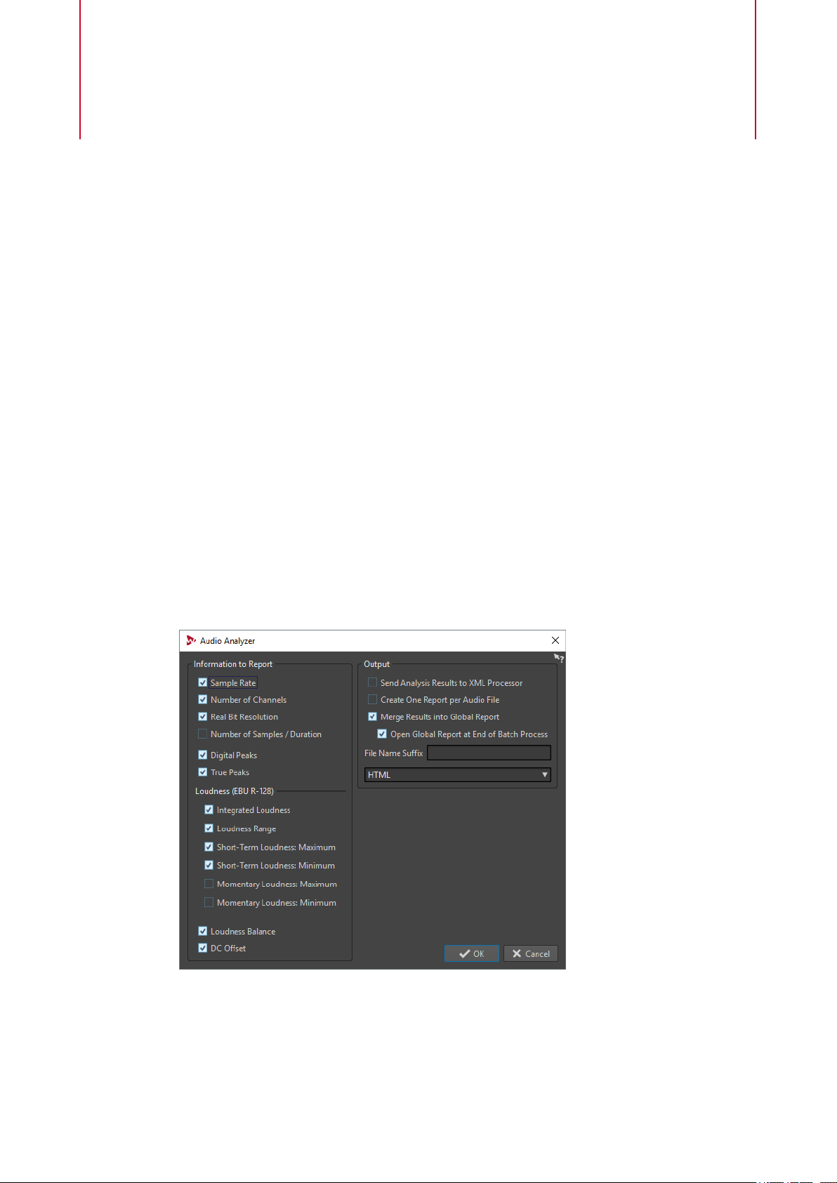
Batch Processing Plug-ins
In the Batch Processor window, you can add a sequence of plug-ins that can be used to process
a batch of audio les. These plug-ins can be standard plug-ins available from the Master
Section, oine processes available in the Audio Editor, and plug-ins that are only available
within batch processing.
The following batch processor plug-ins are described in the WaveLab Pro Operation Manual:
● Loudness Normalizer
Pitch Quantize
●
Pitch Correction
●
● Pan Normalizer
●
Time Stretch
Audio Analyzer
This plug-in allows you to generate text les with statistics about the audio les in a batch
process.
This monopass plug-in is exclusive to the Batch Processor window.
If you want to analyze les without writing anything, select No Output in the Output tab of the
Batch Processor window.
85
Page 86

Batch Processing Plug-ins
Audio Analyzer
Information to Report
In this section you specify which information to include in the output. The following information
can be included:
● Sample rate
● Number of channels
● Real bit resolution
● Number of samples/duration
● Digital peaks
● True peaks
● Integrated loudness
● Loudness range
● Short-term loudness (maximum)
● Short-term loudness (minimum)
● Momentary loudness (maximum)
● Momentary loudness (minimum)
● Loudness balance
● DC Offset
Output
In this section you set up the output of the Audio Analyzer. The following options are available:
Send Analysis Results to XML Processor
If this option is activated, the analysis results are passed as parameters to the XML or
HTML output of the batch processor.
Create One Report per Audio File
If this option is activated, one report is created for each audio le in the batch
process. The audio
Merge Results into Global Report
If this option is activated, the results of the analysis are merged into a global report.
The audio
Open Global Report at End of Batch Process
If this option is activated, a global report opens after the batch process.
File Name Sux
Lets you specify a le name sux. This is necessary when you are using this plug-in
multiple times in a batch process, for example, to see the stats before and after
specic plug-ins.
Use different suxes for each instance of the Audio Analyzer plug-in used in the
processing chain.
le name is used as the report le name.
le name is used as the report le name.
Output format
Lets you select the output format. The following formats are available:
● Pure text
● HTML
● Adobe PDF
● Open Oce
● Spreadsheet
86
Page 87
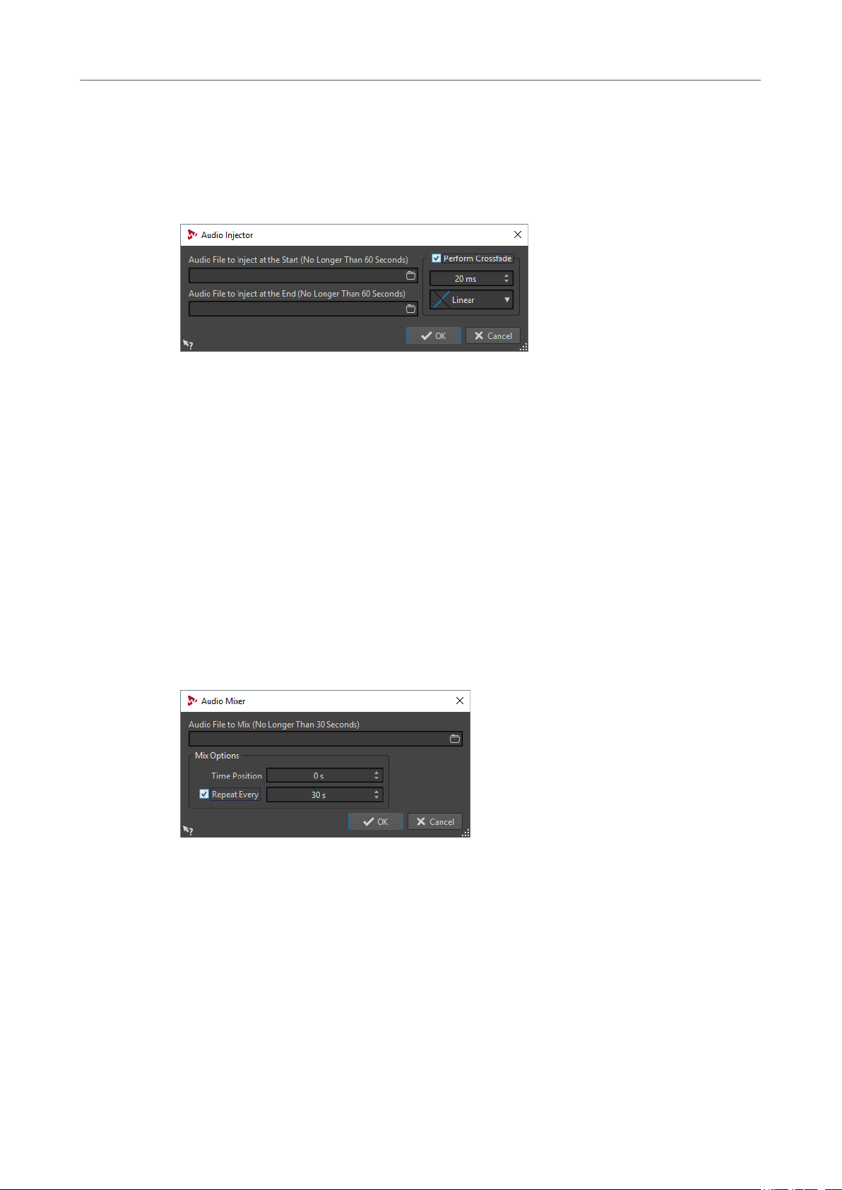
Batch Processing Plug-ins
Audio Injector
● XML
Audio Injector
This plug-in allows you to insert an audio le at the beginning and/or end of the audio le being
processed. The inserted
This monopass plug-in is exclusive to the Batch Processor window.
Audio File to Inject at the Start (No Longer Than 60 Seconds)
Species the audio le to be added before the main audio le.
Audio File to Inject at the End (No Longer Than 60 Seconds)
Species the audio le to be added after the main audio le.
le can also be crossfaded with the original audio le, if required.
Perform Crossfade
Audio Mixer
This plug-in allows you to mix an audio le with other audio les. The mix-in happens from a
specied time and can optionally be repeated at a specied interval.
For example, you can insert a spectral watermark into the audio spectrum or you can insert beep
sounds to mark an audio le as demo material.
This monopass plug-in is exclusive to the Batch Processor window.
Audio File to Mix (No Longer Than 30 Seconds)
Allows you to select a crossfade time and shape for the crossfade between the main
audio
le and the injected audio le.
Allows you to select the audio le that you want to mix into other audio les. The
audio le must be no longer than 30 seconds.
Time Position
Allows you to specify the time position at which the audio le will be mixed in.
Repeat Every
If this option is activated, you can specify the time after which the audio le is
repeatedly mixed in.
87
Page 88
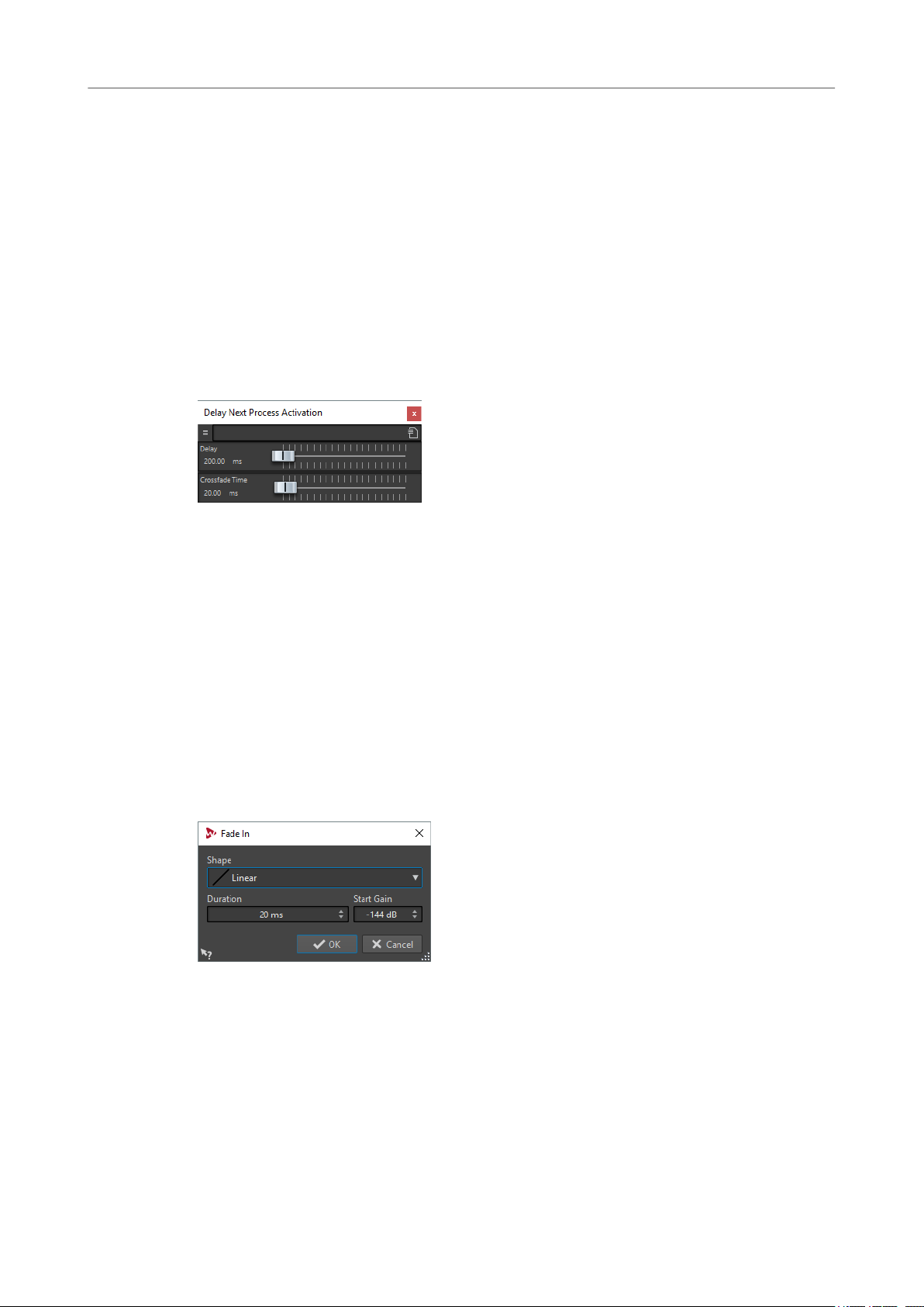
Batch Processing Plug-ins
DC Remover
DC Remover
This plug-in allows you to remove any DC Offset from an audio le.
It is useful to apply this plug-in rst in a batch before other plug-ins to avoid further processing a
le containing any DC Offset. For example, an audio le that has a DC offset is not at its loudest
possible volume when normalized, because the offset consumes headroom.
This multipass plug-in is available in the Batch Processor window and as an oine processor in
Audio Editor.
the
Delay Next Process Activation
This plug-in allows you to delay the processing of the next VST plug-in in the plug-in chain for a
certain time.
This monopass plug-in is exclusive to the Batch Processor window.
Delay
Species the duration until the wet signal starts to fade-in the dry signal.
Crossfade Time
Species the duration of the crossfade time.
Fade In/Fade Out
This plug-in allows you to fade the beginning (Fade In) or the end (Fade Out) of a batch audio
le. You can choose the length and shape of the fade, its duration, and the gain you want it to
start/end at.
The fade plug-ins are exclusive to the Batch Processor window. Fade In is a monopass plug-in
and Fade Out is a multipass plug-in.
Shape
Determines the shape of the fade.
Duration
Determines the duration of the fade.
Start Gain/End Gain
Determines the gain with which the fade starts. It ends with 0 dB.
88
Page 89
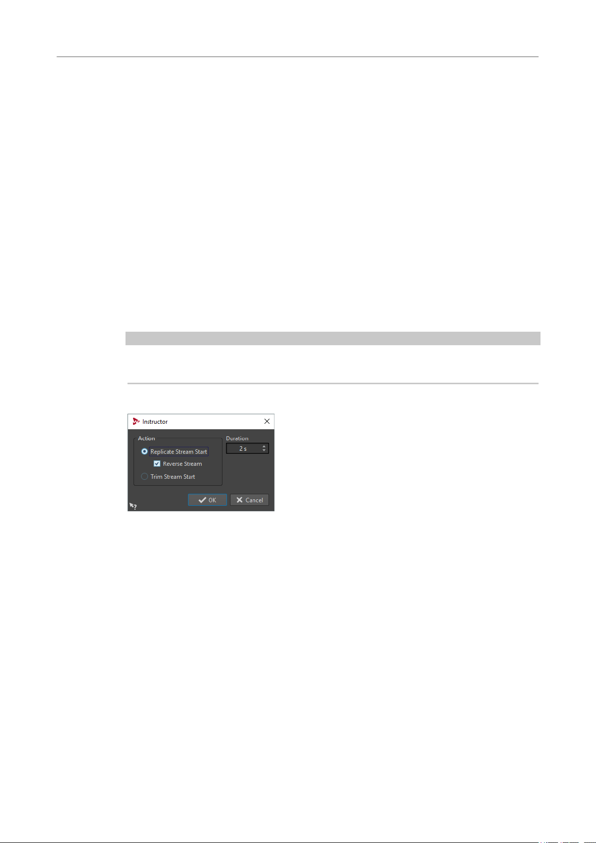
Batch Processing Plug-ins
Instructor
Instructor
Instructor is a special utility plug-in that allows you to instruct the next plug-in in the batch with
information about the audio it needs to process. This is useful for situations where you want to
use monopass plug-ins that require an analysis stage that is not available at this point.
In effect, the Instructor plug-in turns a monopass plug-in into a dual pass one. Some monopass
plug-ins, such as DeNoiser or DeBuzzer, need to learn about the audio they are to process
before they can begin processing correctly. The
because it can teach the next plug-in in the audio chain about the audio it is about to process.
The Instructor plug-in must be used as a pair:
1. The rst instance replicates the start of the audio stream. This means the next plug-in in
the chain receives the start of the audio stream twice.
2. The second instance of the plug-in comes after the plug-in being instructed. It cuts out the
extra audio injected by the
For example, this means that the DeNoiser plug-in has time to suciently analyze the audio
stream before the second stream start is injected. The “badly” processed rst part of the stream
is skipped by the second instance of the Instructor plug-in.
You can set the Instructor plug-in to replicate up to 20 seconds of audio.
Instructor plug-in can help in this situation,
rst instance of the Instructor plug-in.
NOTE
Do not set a value that is longer than the shortest le in the batch, otherwise a short le is over
truncated by the second instance of the plug-in.
This monopass plug-in is exclusive to the Batch Processor window.
Replicate Stream Start
Injects the start of the audio stream twice into the next plug-ins. This action must be
selected for the
Reverse Stream
If this option is activated, the start of the stream is injected rst in reverse sample
order, then in normal sample order. This changes nothing from the spectrum
analysis point of view, but it improves the transition between the repeated streams.
Trim Stream Start
Skips the start of the audio stream. This action must be selected for the second
instance of the Instructor plug-in.
rst instance of the Instructor plug-in.
Duration
Species how much audio to replicate or skip.
89
Page 90

Batch Processing Plug-ins
Level Normalizer
Level Normalizer
This multipass plug-in allows you to raise or lower levels so that the signal peaks exactly at the
specied value just before it is converted to a le.
Peak Level
Specify the highest level of any audio sample.
Stereo Link
Applies the gain to both channels.
Mix to Mono
Mixes the left and right channels. The resulting mono le gets the specied peak
level. This ensure a clip-less mix.
Only if Clipping
Only applies a gain change if the audio le is beyond the reference peak level at
some point. If not, the signal is untouched.
Loudness Meta Normalizer
This plug-in allows you to normalize a batch of les to the same loudness, while taking the EBU
R-128 loudness measurement and a true peak analysis into account.
The purpose of this plug-in is to achieve the same loudness in all les (the highest loudness
found, if possible), while being certain that no le clips. For each le, a specic gain is computed
by the plug-in once all les have been analyzed and prior to actually applying any gain to achieve
the common loudness. If it is not possible to match the highest found loudness, the level of the
le with the highest loudness is reduced, so that other les can get the same loudness. Because
no peak compression is used, the dynamics is preserved and no distortion is introduced.
This metapass plug-in is exclusive to the Batch Processor window.
Match Loudness
Select what loudness the clip should get. The following options are available:
● Match loudest audio le
90
Page 91
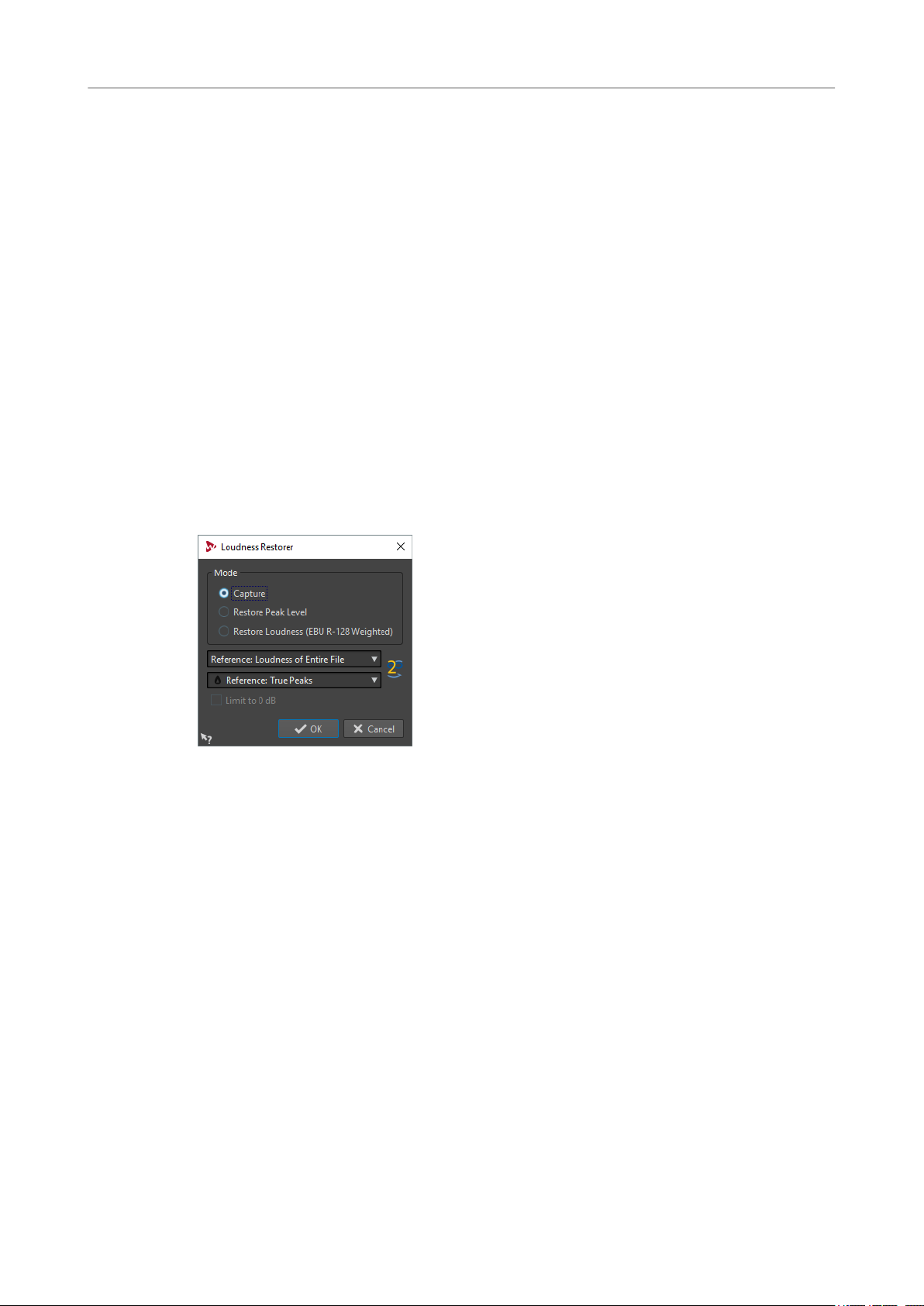
Batch Processing Plug-ins
Loudness Restorer
● Match maximum achievable loudness
● Match specic loudness
Loudness
Determines the specic loudness to match. For example, -23 LUFS if you want to
follow the EBU R-128 recommendation for broadcast.
Reference
Select whether WaveLab should use as reference the loudness of the entire clip (EBU
R-128 recommendation), the average loudest 3 second audio section (
Loudness Range), or the loudest 3 seconds audio section (Maximum Short-Term
Loudness).
Peaks
Select whether WaveLab should refer to sample values (digital peaks) or to analog
reconstructed values (true peaks).
Loudness Restorer
Loudness Restorer captures the loudness at a specic point in the audio chain and restores that
loudness at another point. For this reason, the Loudness Restorer must be inserted in pairs into
the signal chain: one plug-in for capturing and one plug-in for restoring.
Top of
This multipass plug-in is exclusive to the Batch Processor window.
Mode - Capture
The rst instance in the plug-in pair must be set to this mode. This makes the plug-in
read the signal at this position in the audio chain.
Mode - Restore Peak Level/Restore Loudness (EBU R-128 Weighted)
The second instance in the plug-in pair must be set to one of these modes. Select
one of these options if you want to use peak levels as a basis for determining what is
considered equal level. Restore Loudness (EBU R-128 Weighted) produces a more
natural result than Restore Peak Level.
Reference menu
Select whether WaveLab should use as reference the loudness of the entire le (EBU
R-128 recommendation), the average loudest 3 second audio section (Top of
Loudness Range), or the loudest 3 seconds audio section (Maximum Short-Term
Loudness).
Peak menu
Select whether WaveLab should use sample values (Digital Peaks) or analog
reconstructed values (True Peaks).
91
Page 92

Batch Processing Plug-ins
Meta Leveler
Limit to 0 dB
If this option is activated, the restoration process will never result in levels above 0
dB.
Meta Leveler
This plug-in allows you to change the level of a batch of les consistently.
The core purpose of this plug-in is to apply the same gain to all les, while being certain that a
specic peak level never exceeds in any le. The unique gain that you want to apply is (possibly)
reduced by the plug-in, once all les in the batch have been analyzed, and prior to actually
applying the gain across the batch.
Resizer
This metapass plug-in is exclusive to the Batch Processor window.
Gain
Applies the specied gain to each le. The actual gain can be lower and even
negative, to not exceed the value specied in the Maximum Peak eld.
Maximum Peak
Species the maximum peak level that any audio le should get at the end of the
process.
Peaks
Select whether WaveLab should refer to sample values (digital peaks) or to analog
reconstructed values (true peaks).
This plug-in allows you to specify the duration of all audio les in the batch, and to choose
whether to insert silence after the end of the chosen duration.
This monopass plug-in is exclusive to the Batch Processor window.
Stereo to Mono
This plug-in allows you to mix a stereo signal down to a mono signal while being certain not to
clip while mixing channels because of the multipass approach. You can choose to use the same
92
Page 93
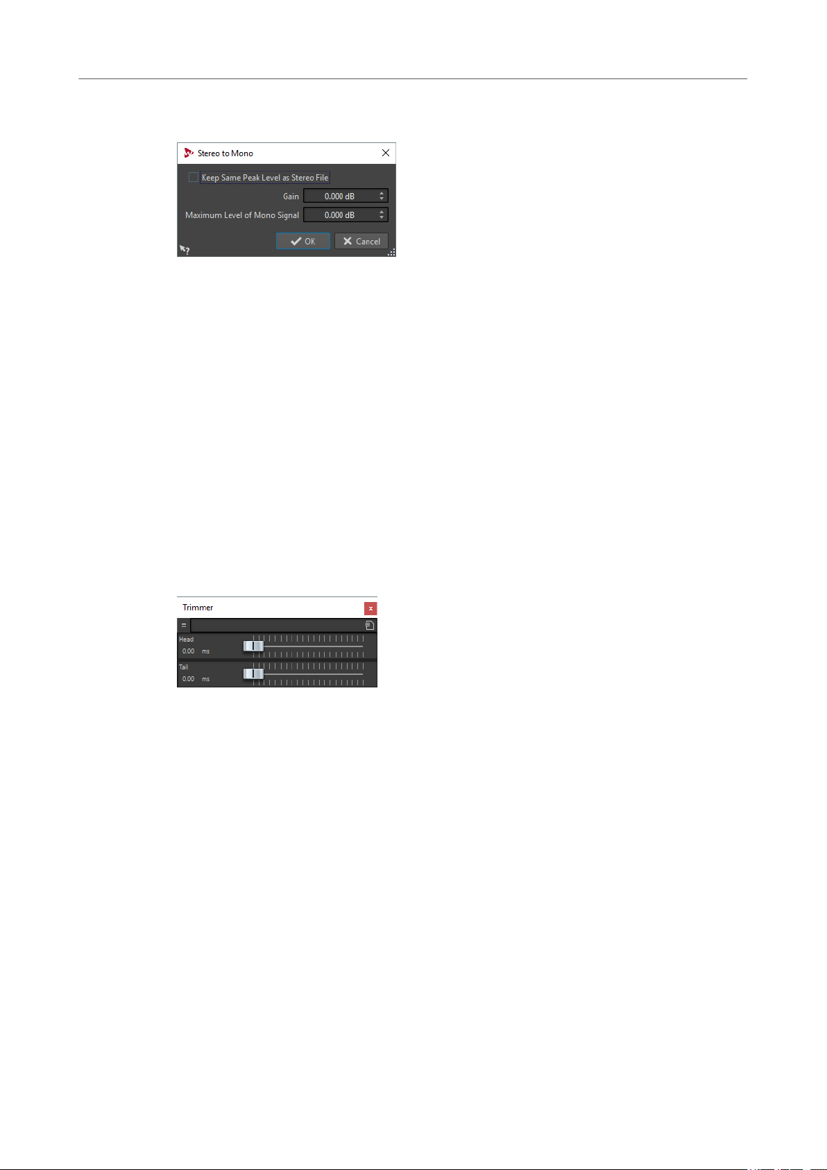
Batch Processing Plug-ins
Trimmer
peak level that the stereo le contains, or set the gain to be applied and/or the maximum level to
be reached in the resulting mono le.
This multipass plug-in is exclusive to the Batch Processor window.
Keep Same Peak Level as Stereo File
If this option is activated, the peak level of the resulting mono le is the same as the
peak level of the original stereo le.
Gain
Species the increase or decrease in peak level for the resulting mono le, in relation
to the original stereo
Maximum Level of Mono Signal
Species the peak level that the resulting mono le must not exceed. This ensure
that the output le never clips. This way, the result never exceeds 0 dB, regardless of
the
le.
specied Gain value.
Trimmer
This plug-in allows you to remove a specied duration (from 0 ms to 60 s) of audio from the head
and/or tail of an audio le.
This monopass plug-in is exclusive to the Batch Processor window.
93
Page 94

Index
A
ASIO
Audio Input 84
External Gear 83
Plug-ins 83
Audio Analyzer 85
Audio Injector 87
Audio Input 84
Audio Mixer 87
AutoPan 29
B
Batch processing plug-ins 85
Audio Analyzer 85
Audio Injector 87
Audio Mixer 87
DC Remover 88
Delay Next Process Activation 88
Fade In/Fade Out 88
Instructor 89
Level Normalizer 90
Loudness Meta Normalizer 90
Loudness Restorer 91
Meta Leveler 92
Resizer 92
Stereo to Mono 92
Trimmer 93
Brickwall Limiter 30
Compressors (continued)
Vintage Compressor 74
VSTDynamics 75
CurveEQ 34
D
DC Remover 88
DeBuzzer
DeClicker 26
DeEsser 34
Delay Next Process Activation 88
Delays
DeNoiser 26
Distortion 36
Dithering
Dithering plug-ins 80
DualFilter 37
Ducker 4
Dynamic EQ
27
RestoreRig 24
RestoreRig 24
MonoDelay 51
PingPongDelay 58
StereoDelay 66
RestoreRig 24
UV22HR 82
Internal dithering 80
MBIT+™ dithering 80
MasterRig 18
C
Channel Extractor 31
Chopper Effects
AutoPan 29
Chorus Effects
Chorus 31
StudioChorus 69
Clip effects
Ducker 4
Compressor
MasterRig 13
Compressors
Compressor 32
DeEsser 34
Maximizer 48
MultibandCompressor 52
Tube Compressor 73
E
EBU R-128
Audio Analyzer 85
Loudness Meta Normalizer 90
Envelope Shapers
EnvelopeShaper 37
MultibandEnvelopeShaper 54
Equalizer
MasterRig 17
Expanders
Expander 38
MultibandExpander 56
External Gear 83
F
Fade In/Fade Out 88
Frequency 40
94
Page 95

Index
G
Gates
Gate 43
VSTDynamics 75
GEQ-10
GEQ-30 45
45
I
Imager
MasterRig 22
Instructor 89
Internal dithering 80
iZotope
MBIT+™ dithering 80
L
L/R to M/S 47
Legacy plug-ins 79
Level Normalizer 90
Leveler 5
Leveler Multi 6
Limiter
MasterRig 10
Limiters
Brickwall Limiter 30
Limiter 46
Maximizer 48
VSTDynamics 75
Loudness Meta Normalizer 90
Loudness Restorer 91
M
M/S to L/R 47
Magneto II 47
MasterRig 6
Compressor 13
Dynamic EQ 18
Equalizer 17
Imager 22
Layout 6
Limiter 10
Modules 9
Saturator 20
Settings 9
Maximizer 48
MBIT+™ dithering 80
Meta Leveler 92
Mix6to2 49
Mix8to2 50
MonoDelay 51
MonoToStereo 51
MultibandCompressor 52
MultibandEnvelopeShaper 54
MultibandExpander 56
P
Peak Master 23
PingPongDelay 58
Plug-ins
ASIO 83
Batch processing 85
Dithering 80
Legacy 79
VST 3 29
WaveLab-specic 4
PostFilter
59
R
Recording
Audio Input 84
Resampler 4
Resizer 92
RestoreRig 24
Layout 24
Modules 25
REVelation 61
RoomWorks 63
RoomWorks SE 66
S
Sample rate
Resampler 4
Saturation
Magneto II 47
Saturator
MasterRig 20
Silence 28
Stereo Expander 28
Stereo to Mono 92
Stereo Tools 68
StereoDelay 66
StereoEnhancer 67
StudioChorus 69
StudioEQ 70
T
TestGenerator 72
Trimmer 93
Tube Compressor 73
U
UV22HR 82
V
Vintage Compressor 74
VSTDynamics 75
O
Octaver 58
95
 Loading...