

Page 1

Time Base – Operation Manual
Page 2

Operation Manual by D. Popow
The information in this document is subject to change without notice and does not represent a commitment on the part of Steinberg Media Technologies GmbH. No part of
this publication may be copied, reproduced or otherwise transmitted or recorded, for
any purpose, without prior written permission by Steinberg Media Technologies GmbH.
All product and company names are ™ or ® trademarks of their respective owners.
© Steinberg Media Technologies GmbH, 2004.
All rights reserved.
Page 3

Table of Contents
Page 4

7 Preface
9 Package Contents and
Installation
10 Package Contents
10 Installation – Connections –
Getting Started
11 Important Safety Instructions
12 Driver Software Installation
12 Windows PC Drivers
12 Mac OS X Drivers
13 Features and Basic
Settings
14 Time Base – Brief Overview
15 Basic Settings
17 Typical Setup
Examples
18 Basics
19 Computer Connection
20 Settings in Nuendo
20 Time Base
22 Setting up the Time Base
9-Pin Device Control Panel
24 Time Base Slave
25 Setup Examples
25 LTC as the Master
25 MTC as the Master
27 Internal Clock as the Master
28 House Sync (Blackburst) as
the Master
30 Machine Control
34 Video functions
36 Digital Varispeed
37 Reference
38 Basics
40 Selecting Pages in the
Display
40 The Main Page – Display
page P.1
48 VITC and Time Code
Inserter – Display page P.2
50 Varispeed, Word Clock 2,
3, 4 and AES/EBU Output –
Display page P.3
52 Time Code Test and Offset
– Display page P.4
54 LTC output, Preroll, USB
port and System Video
settings – Display page P.5
57 Selecting tracks and
switching Track Selection
pages – 9-Pin-Machine A –
Display page P.A
59 Track Selection Virtual
Machine – Display page P.V
61 Service and Machine
Pages
62 Calling up the Service and
Machine Pages
62 Virtual Machine and MMC
settings – Display page SP1
65 Presets, Time Code level,
Red light and SYSEX
handling, Initialization after a
Software Update – Display
page SP2
68 Test and Setup Machine A
72 Preset Tables
TIME BASE
4 Table of Contents
Page 5

77 Connections
78 Connections on the rear panel
78 VITC-Reader/Generator/
Inserter
78 Video Sync In/Out
78 LTC – Longitudinal Time
Code
79 VST System Link
79 Word Clock OUT 1-4
79 USB
79 9-Pin
80 GPI/O | MIDI
80 Wiring Examples – GPI/O
81 Power and Protection
Circuit
82 Technical Data
83 VST System Link
84 What is VST System Link?
85 How does VST System Link
work?
86 VST System Link –
Troubleshooting
87 Glossary
TIME BASE
Table of Contents 5
Page 6

TIME BASE
6 Table of Contents
Page 7

1
Preface
Page 8

Congratulations on your purchase of Nuendo Time Base!
The Time Base offers perfect solutions for sample-accurate synchronization
of digital audio production systems like Nuendo via House Sync (Blackburst), AES/EBU – VST System Link, LTC or VITC with analog or digital
audio and video tape recorders, mixing desks, sequencers etc.
Time Base combines the functional domains Word Clock (AES/EBU –
VST System Link), Time Code, Machine Control and Virtual Machine.
It reads and generates the standard Time Code formats LTC, VITC, MTC
and 9-pin. Generated Time Code is in sync with the video sync signal.
A built-in Video Inserter lets you visually insert Time Code into the video
picture or add VITC to the video signal.
An integrated 9-pin interface lets you control external 9-pin compatible
devices, e.g. a Betacam video recorder, Tascam DA88, DA98, MMR8 or
Doremi V1.
Time Base can also be used as a Virtual Machine. This lets you, for instance, remote control Nuendo from 9-pin Edit Controllers, and mixing
desks that provide 9-pin machine control (SSL, NEVE…). The GPI/O
socket on the Time Base provides the possibility to realize Red light
(“on air”) control.
Time Base provides a two-line display and four ergonomically positioned
buttons. These can be used to call up various display pages and set individual parameters. Settings can also be made from within Nuendo, provided that the corresponding application is connected to the Time Base
via USB. When you load a Project, all relevant Project settings are automatically transferred to the Time Base.
We are sure that using Time Base will simplify your studio work and will
help you to become even more productive.
We hope that you have fun using Time Base!
For their continuous support during the development of Time Base,
we would particularly like to thank:
Achim Kruse, Burkhard Bürgerhoff – C-Lab
The Steinberg team
TIME BASE
1 – 8 Preface
Page 9

2
Package Contents and
Installation
Page 10

Package Contents
• Time Base
• Power Cable
• User Manual
• Driver CD
• Warranty Card
Installation – Connections – Getting Started
Time Base is designed to be mounted in a 19“ rack. It should either be installed in a 19” rack or placed on a stable surface, as it can fall down and
be damaged. Proximity to heating or cooling equipment should be avoided
(operational temperature range 15-35 degrees Celsius).
The power connector should only be connected to an earthed power
socket using an earthed power cable delivering 110-240V.
All signal connections should be made with shielded cables! All connections, except LTC in/out (analog audio), should be made with cables of
the correct impedance, suitable plugs and termination, if necessary (see
page 82).
❐
For some System setup examples see page 17.
TIME BASE
2 – 10 Package Contents and Installation
Page 11

Important Safety Instructions
• Do not leave the power cable where people walk, in order to avoid any
accidental interruption of power. If an extension block is used, then care
should also be taken that all the connected devices do not together exceed the maximum safe current draw.
• Disconnect the power before cleaning.
• Take care that no foreign objects get inside the machine. They could come
into contact with current-conducting components or cause a short circuit,
which in turn could cause a fire or an electric shock. Under no circumstances should liquids be allowed to get inside Time Base.
• When the cover of Time Base is removed, it is possible that dangerous
current-carrying parts will be exposed to human contact. Therefore, all service operations should be carried out only by authorized service personnel.
• Time Base should under no circumstances ever be used in proximity to
water.
TIME BASE
Package Contents and Installation 2 – 11
Page 12

Driver Software Installation
Windows PC Drivers
When you connect Time Base to your computer for the first time, Windows
will recognize the new hardware component and start its “Add New Hardware Wizard”.
• Insert the Driver CD into your CD-ROM drive and follow the instructions
displayed on your computer screen.
The necessary driver software – a Firmware Loader and the actual Time Base driver – will
now be installed during two separate installation processes.
❐
You can safely ignore alert messages like “Digital signature not found”, “Do
not install driver”, “Driver not certified”. Simply continue with the installation.
• Restart your computer when the installation procedure has been completed.
Mac OS X Drivers
When you have connected the hardware for the first time and started the
computer, you can install the driver software from the Driver CD-ROM.
1. Start driver installation by double clicking on the Time Base Driver icon.
2. Follow the instructions on the screen and restart your computer when the
procedure has been completed.
TIME BASE
2 – 12 Package Contents and Installation
Page 13

3
Features and Basic Settings
Page 14

Time Base – Brief Overview
Time Base is a universal synchronization and control device for digital audio
and video in all fields of studio production.
Time Base combines the following four functional domains in one compact
device:
• Time code
• Word-Clock (AES/EBU digital zero or AES/EBU for VST System Link)
• Machine Control (MMC and P2 protocol/9-pin-control)
• Virtual Machine (emulated 9-pin/P2 machine)
Time Base offers the following functions:
• Reads and writes all standard Time Code formats: LTC, VITC, MTC and 9-pin
(serial Time Code).
The Time Code generator is in sync with the video sync signal.
• Synchronizes digital audio systems to House Sync (Blackburst, video), AES/EBU
(digital audio), LTC (“Longitudinal Time Code”, e.g. coming from an analog 24
track tape recorder).
• Supports all sample rates between 16 and 192 kHz including pull-up/pull-down
(NTSC).
• Includes a synchronous digital Varispeed engine.
• Converts MMC to 9-pin machine control.
The built-in 9-pin bus can e.g. control Betacam VCR, Tascam DA88, DA98,
MMR8, Doremi V1 etc.
• Can be used as a Virtual Machine. This lets you remote control several hard disk recording systems from various points without having to switch the “remote control”.
The Virtual 9-pin machine functions make it possible to control Nuendo from 9-pin
edit controllers and from mixing desks that are equipped with a 9-pin machine controller (e.g. SSL, NEVE).
• Can display (insert) Time Code in(to) video frames in two sizes and four display
modes. The Time Code can be freely positioned within the frame.
TIME BASE
3 – 14 Features and Basic Settings
Page 15

Basic Settings
Before each session, the following basic settings should be made or
checked. Both of the following settings would normally be set according
to the standard settings used in the respective country:
Time Base
Display Page
P.5 SYS-VIDEO
P.1 FRM
Parameter Explanation Options
Video frame
rate
Time code
frame rate
E.g. 25 frames in Europe (PAL) or
29 frames in USA/Canada (NTSC).
25 frame (PAL), 29, or 29D (drop)
frames (NTSC).
If the Time Base is being driven by video sync, the Time Code frame rate
will be automatically set to the video frame rate.
❐
The frame rate of the connected devices must be set to the same value!
Time Base
Display Page
P.1 SR
Parameter Explanation Options
Sample rate The Sample Rate should be set to the
desired value for the project, and should
be maintained unchanged throughout
the whole project (e.g. 44.1 for CD, 48
for Video/Film, 192 for DVD Audio).
❐
The Sample of synchronized devices must be set to the same value! When
you make the settings for a new Project in Time Base, Nuendo will automatically recognize them. When you load a Project in Nuendo, Time Base will
automatically be set to the same settings.
TIME BASE
Features and Basic Settings 3 – 15
Page 16

In the case of incoming pre-produced material, all three parameters
should be set to match, or the delivered material should be converted to
the “house” standard (if the latter, please do so while synchronized!).
Time Base
Display Page
P.3 VARSP=OFF
Parameter Explanation Options
Varispeed In this case, this parameter should be
set to OFF.
• When you install and check out Time Base for the first time, it is a good idea to
start out with one of the Time Base presets (see page 65). The individual Time
Base parameters are described in detail on page 37.
TIME BASE
3 – 16 Features and Basic Settings
Page 17

4
Typical Setup Examples
Page 18

Basics
A few words of introduction to the technical problems which can occur in
synchronization in an all-digital or hybrid analog/digital studio setup:
Basically, there are two different synchronization procedures.
One of the available audio or video machines becomes the master.
But the type of Time Code often used, LTC, contains two information
streams:
• The visible time information (hh:mm:ss:ff).
• The invisible tempo information (Clock).
The LTC is thus used as position and Word Clock reference! It is this
which may cause the problem, that errors in the Master Clock, i.e. in the
Time Code (jitter, dropouts, wow & flutter in the master device) are passed
on to all connected slave devices. Time Base is conceived in such a way
that such problems are contained as much as is technically possible.
The signal used for synchronization in this case is referred to as “self-clocking”, because the principal aim is to transmit a clock signal (speed, Word
Clock) in which the other data (Time Code numbers in LTC, digital audio in
AES/EBU) happens to be included. Precisely because of this unavoidable
passing on to slave machines of errors caused in part by the system itself,
special care should be taken that the Time Code is error-free.
The more reliable procedure is this:
One Master Clock is used to synchronize all devices (data streams) in the
studio. The Master Clock is the only device that generates a sync signal
(e.g. Blackburst or Word Clock). When using Blackburst, Time Base
uses this to generate the Digital Audio Clock. All connected audio and
video devices there run from the same pace and use this as a speed reference. This avoids the error described above.
This procedure only works with devices that can be synchronized externally.
This includes not just audio and video devices, but also Time Code generators as in Time Base). This means that when the Time Code generator has
clocked another second, a digital audio signal with a 48 kHz sampling frequency for example should have played back exactly 48,000 samples). This
procedure also means that tempo information is derived from a precise and
stable source, which drives everything!
Time Base contains just such a clock.
TIME BASE
4 – 18 Typical Setup Examples
Page 19

Computer Connection
Time Base must be connected to the computer via its USB port which is
located on the rear panel. USB is used to transfer control and configuration data.
VST System Link is used for synchronization. All time-related data is
therefore transferred via VST System Link.
Synchronization via USB-Serial-TC is also possible, if necessary.
TIME BASE
Typical Setup Examples 4 – 19
Page 20
Settings in Nuendo
❐
A detailed description of the Time Base Setup windows in Nuendo can be
found in the documentation and Online Help systems of the corresponding
– Time Base supporting – program versions.
1. Switch on Time Base, then start Nuendo.
Various setup parameter sets are available in Nuendo’s Devices Setup dialog for the different Time Base setup options.
2. You can open this dialog by selecting “Device Setup…” on the Devices
menu.
3. First, use the “ADD/Remove” tab in the dialog to add the respective Device Class, if necessary or select one in the Devices list on the left side of
the dialog.
Several Device Classes are available for Time Base. Click on the “Setup” tab, to make the
corresponding settings.
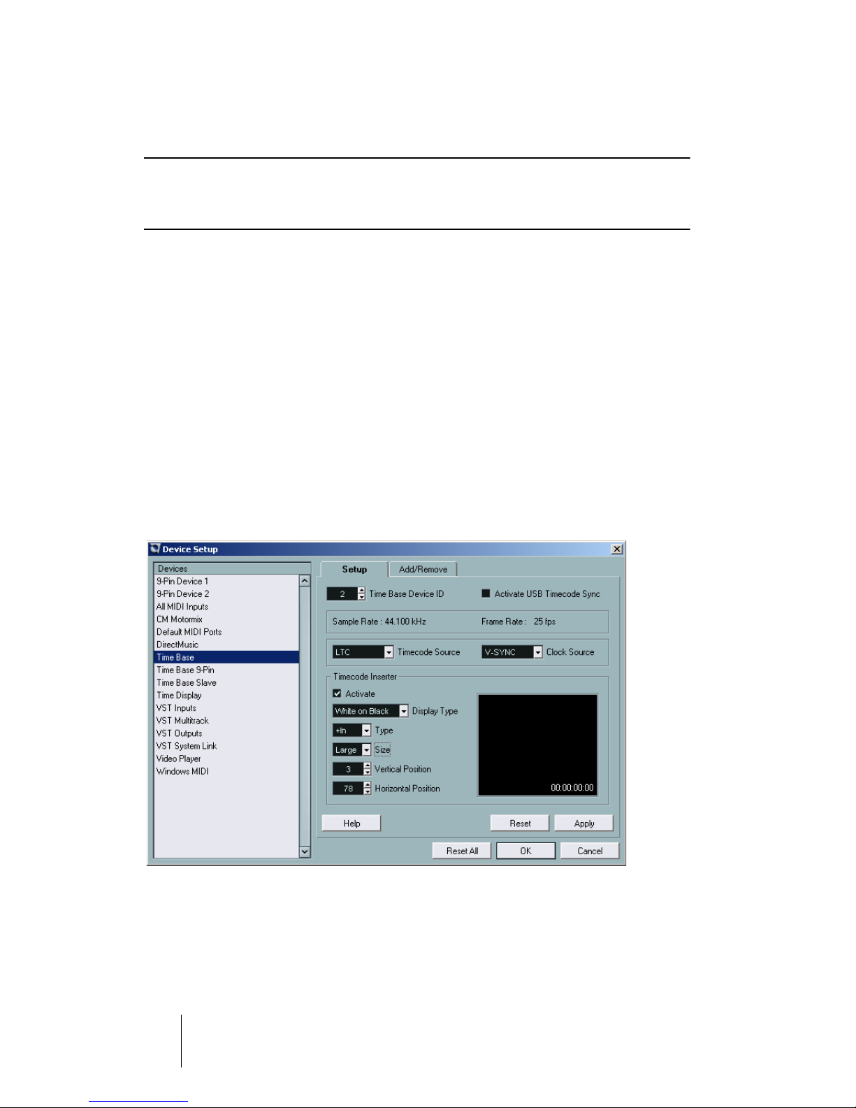
Time Base
Here you can make basic settings.
TIME BASE
4 – 20 Typical Setup Examples
Page 21

Parameter Options Effect
Time Base
Device ID
0 - 126
ID 2 is preset
Device identification number. Must
be set correctly to make sure the
data arrives in the device.
Activate USB
Timecode Sync
Ticked = On
No tick= Off
If this option is activated, the Time
Code synchronization with the
computer takes place via the USB
port.
If the option is set to Off, synchronization with the computer takes
place via the VST System Link
connections between Time Base
and computer.
The parameters Sample Rate and Frame Rate are read only.
Timecode Source LTC, VITC, MTC, M.V (MIDI), M.A
(9-Pin)
Depending on which Time Code
source you select, different options
are available in the Clock Source
pop-up menu.
Clock Source Internal, V-SYNC, LTC-Norm,
LTC-Hold
Timecode Inserter Ticked = On
No tick= Off
The available Clock source
options.
When this option is activated, Time
Base will insert the Time Code into
the video frames (“Burn-in window).
Display Type White on Black,
Black on White,
Display options for the inserted
Time Code.
White Contour,
Black Contour
Type +In, +TC9 Lets you select the Time Code
type displayed by the inserter
(see page 35).
Size Small, Large Display options for the inserted
Time Code.
Vertical Position,
Horizontal Position
Timecode
Positioning field
0 - 127 Lets you numerically position the
inserted Time Code.
Manually by dragging Here you can define the position of
the inserted Time Code within the
video frame by manually dragging
it with the mouse. Note: The real
size of the displayed Time Code is
not shown in this positioning field!
TIME BASE
Typical Setup Examples 4 – 21
Page 22
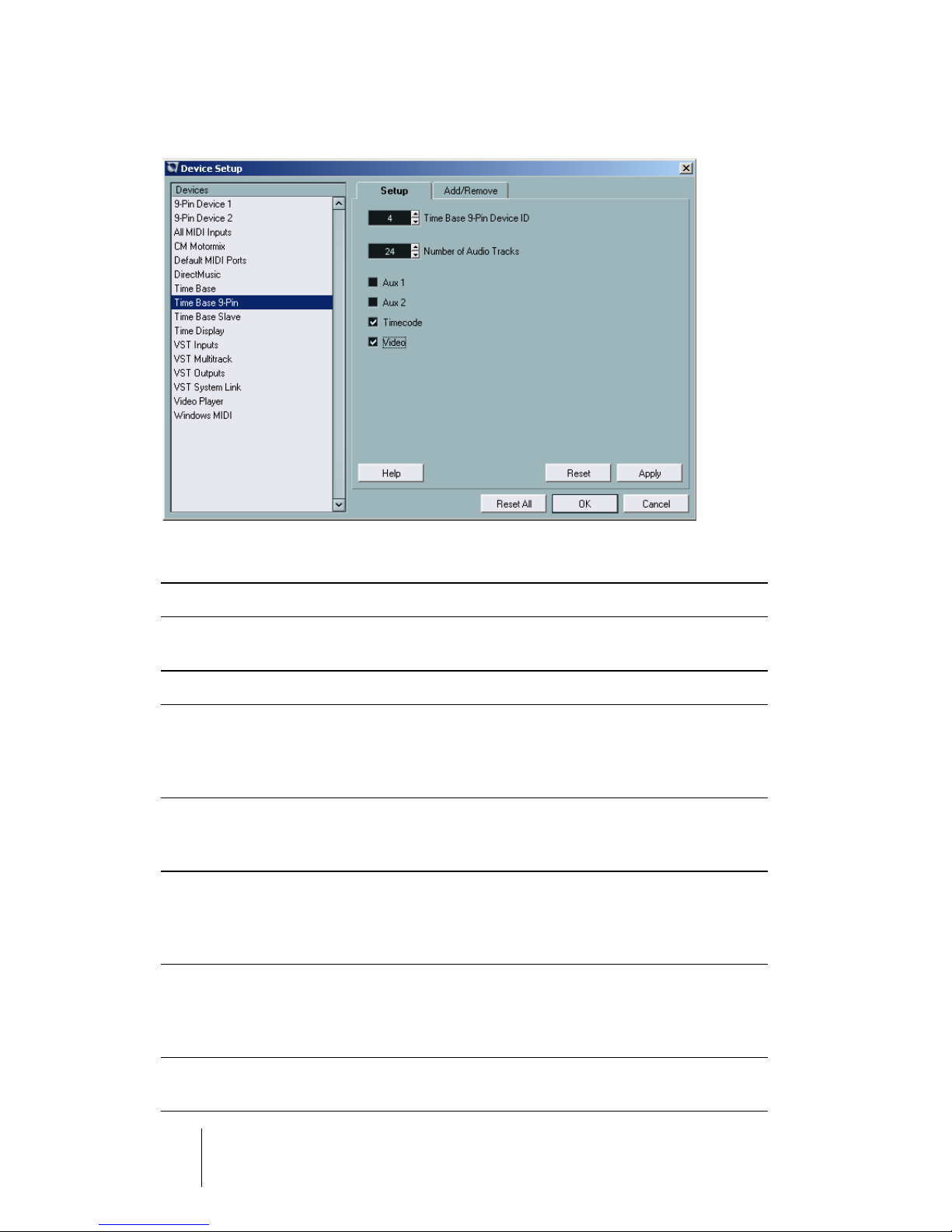
Setting up the Time Base 9-Pin Device Control Panel
Here you make the settings for 9-pin device control (see below). Make sure, that the
corresponding function is available in the 9-pin device that you use.
Parameter Options Effect
Timebase 9-PinDevice ID
The following parameters are used to set up track remote control for the connected machine.
Number of
Audio Tracks
Aux 1, Aux 2 Activate (tick) /
Timecode Activate (tick) /
Video Activate (tick) /
0 - 126 Lets you set the 9-pin device ID. The Nuendo/Time
Base standard value is 4
2 - 64 Lets you define the number of digital audio tracks
available in the connected 9-pin device, which
thereby become visible and can be controlled from
the 9-pin device control panel.
When you activate these parameters, the (analog)
Deactivate (no tick)
Deactivate (no tick)
Deactivate (no tick)
audio tracks appears in the 9-pin device control
panel.
Most 9-pin devices provide special time code tracks.
If you activate this parameter, the time code track of
your 9-pin device appears in the 9-pin device control
panel.
If the connected 9-pin device processes video, you
can use this parameter to make the corresponding
Arm Track control visible in the 9-pin device control
panel.
All tracks available in your 9-pin device should be included in the 9-pin device control panel.
This will give you a better overview and you are always informed about the current track status.
TIME BASE
4 – 22 Typical Setup Examples
Page 23
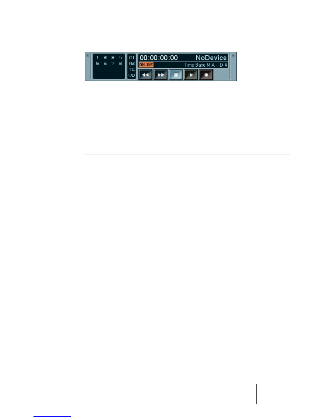
Time Base 9-Pin Device Control Panel
Open this control panel by selecting “Time Base 9-Pin” on the Devices
menu. It can be used to remote control a 9-pin device that you have connected to the Time Base from Nuendo and to arm its tracks.
❐
Which functions are available on this control panel depends on which functions are available in the connected 9-pin device and also on the settings that
you have made in the Time Base 9-pin view of the Device Setup dialog, see
previous page.
Depending on your settings, the following elements (from left to right) may
be visible in the control panel:
• The set up number of audio tracks. These can be armed with a mouse click.
• The Aux 1 and 2 tracks, which some devices make available separately or which
may also be “hidden”, as well as the time code and video tracks. These can be
armed here, too.
• The transport controls control playback and recording functions of the 9-pin device.
• The Online switch must be activated. If it isn’t, remote control is disabled.
• In the upper section of the control panel, the current time code position, the Time
Base status as well as the connected 9-Pin device are displayed.
• To the left of the 9-pin device indicator, the following error messages may become
visible:
<Local> Remote control is deactivated in the external 9-pin device.
<NoTape>
This “error” message is shown when there’s no tape on the connected 9-pin tape recorder.
TIME BASE
Typical Setup Examples 4 – 23
Page 24
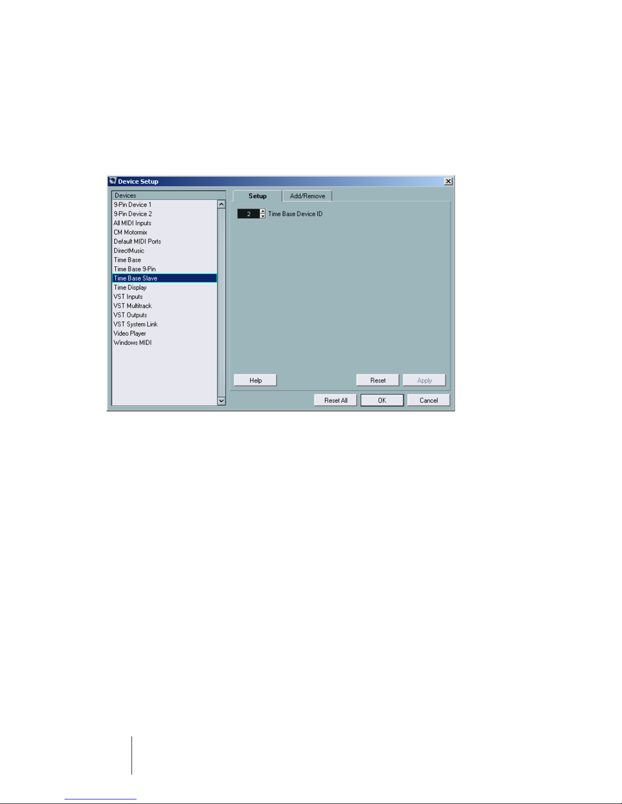
Time Base Slave
Here you can activate remote control of Nuendo by using the combination
of Nuendo and Time Base as a virtual machine. Which functions are actually available for the virtual 9-pin machine depends mainly on the options
available in the external controller unit.
Time Base Slave dialog view in the Device Setup dialog.
The only parameter that you can set here is the Time Base Device ID. It is
preset to its (Nuendo) standard value 2.
TIME BASE
4 – 24 Typical Setup Examples
Page 25
Setup Examples
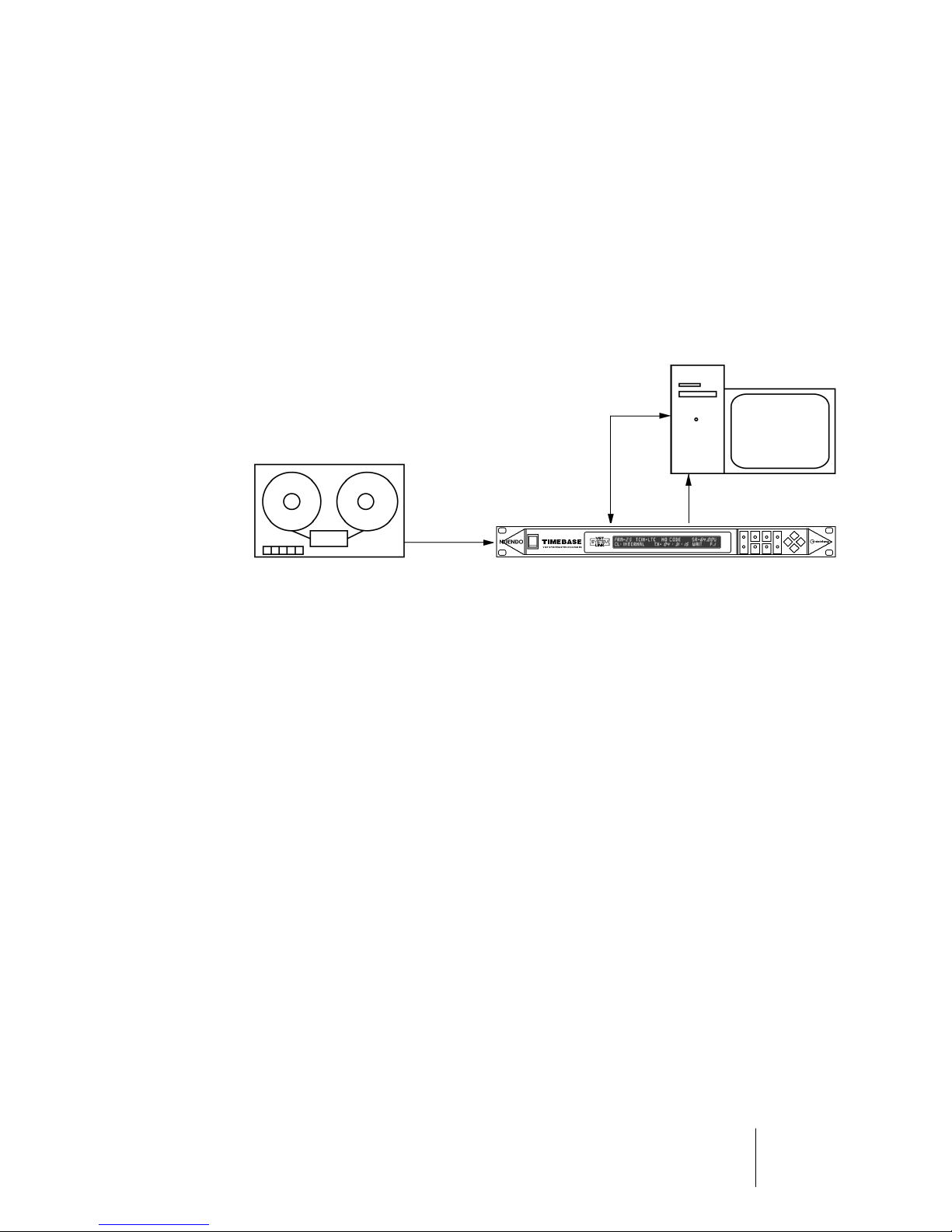
LTC as the Master
This procedure is particularly favoured in music productions. The hard
disk recorder (i.e. Nuendo) is “slaved” to the analog machine (e.g. a 24
track recorder).
Time Base settings:
Connections:
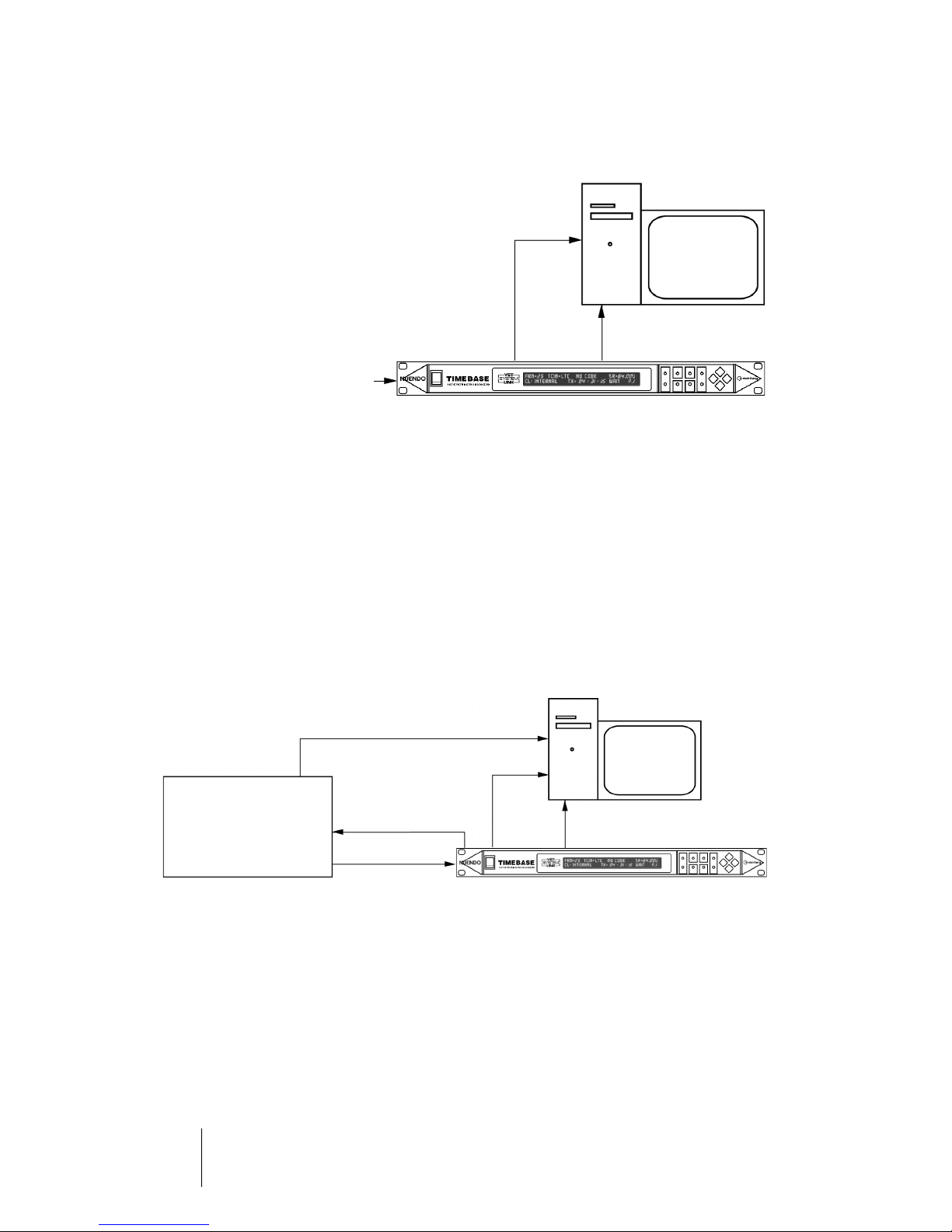
MTC as the Master
Normally in professional situations, this should only be seen as a last resort emergency procedure, i.e. to save a production which otherwise
would be lost. The reason for this lies in the often technically inadequate
implementation of MIDI Time Code, causing MTC to be saddled with high
jitter from external sources. It is impossible to pass on a stable, jitter-free
Word Clock from such an MTC-signal.
TCIN=LTC, CL: LTC-HOLD
USB port
VST System Link
LTC
However, as it is sometimes necessary to perform this conversion (to
continue with a production begun in semi-professional circumstances),
Time Base generates the clean Word Clock necessary for sonic quality
by taking an average value from the incoming MTC. If the jitter in the incoming MTC were allowed to affect the Word Clock, the connected digital devices would all have their audio quality compromised by locking to
such a reference clock, provided that would be possible at all.
Time Base expects MTC input via its 15-pin MIDI|GPI/O socket on its rear
panel. The socket wiring is described on page 80. Examples for 15-pin
connector wiring can be found on page 80.
TIME BASE
Typical Setup Examples 4 – 25
Page 26
Time Base settings:
TCIN=MTC, CL: MTC-HOLD
Connections:
USB port
VST System Link
ext. MTC-In
If you should find yourself in such a situation, you can sometimes chose
the following:
If your MTC source is a stand-alone Hard Disk Recorder with a digital input which can be externally synchronized, you should switch the Word
Clock source of the recorder to “digital in”, having connected it to a Word
Clock output on the Time Base. If you now use the MTC produced by the
recorder as a positional reference, your entire system will follow the external device.
Time Base setting:
CL:INTERNAL
(V-SYNC)/
TCIN=MTC
Connections: stand-alone« HD-Recorder and Nuendo
Audiosignale
USB port
Stand-alone
HD Recorder
Word Clock
VST System Link
MTC
As an alternative, the MTC produced by Time Base can be used as a position reference by the external device. In this case the external device follows the system.
TIME BASE
4 – 26 Typical Setup Examples
Page 27
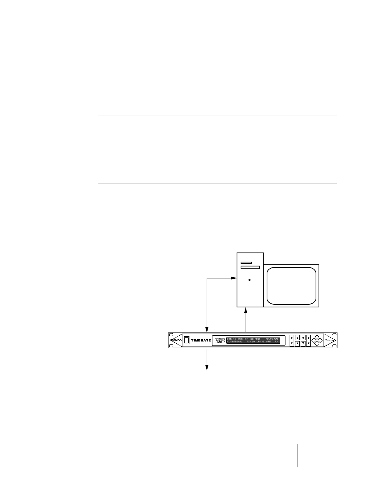
Internal Clock as the Master
A technically perfect procedure: Time Base generates the Word Clock
and VST System Link signals for all the digital devices running in the entire studio. As all devices run in sync, data transfer without interruptions is
also possible. Increased jitter (and associated loss of quality in synchronized audio signals) is thereby prevented.
❐
To prevent misunderstandings, Time Base is always the Timing Master, but
not necessarily the Positional Master. A hard disk recorder, that is synchronized to Word Clock and has a MIDI Time Code output (which must of course
be synchronized to Word Clock) can e.g. control a digital mixer that is also
locked to Word Clock. The user has the impression that the hard disk recorder is the Master while it is in fact only the Positional Master, but not the
Word Clock Master.
Settings:
CL:INTERNAL
If required, the Time Code functions of Time Base can be used to convert
the Time Code format. The technically best solution is to use the Virtual
MIDI Machine the generate a clock synchronized Time Code.
Connections:
USB port
VST System Link
LTC (e.g. to control a Mix Automation)
TIME BASE
Typical Setup Examples 4 – 27
Page 28
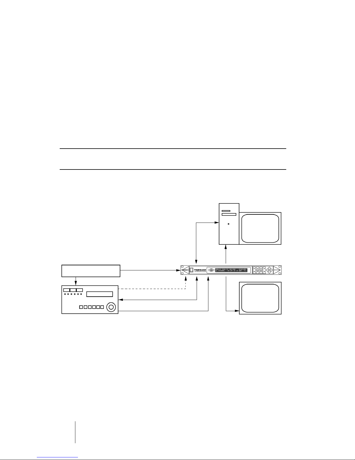
House Sync (Blackburst) as the Master
A second technically perfect procedure: Time Base is connected to a
house sync generator (Blackburst) via the Video Sync In. All the advantages listed in the section "Internal Clock as the Master" on page 27 are
retained. In addition, the Time Code generator is synchronized to video.
This procedure should be used, whenever audio is being edited in sync
with video picture.
If several studios are housed in the same building, they can be linked together via the house clock, and can work in sync, without having to live
with the restrictions of Word Clock connection.
❐
With Word Clock connection, the entire studio would have to work at the
same sample rate.
Settings:
CL:VIDEO/TCIN=LTC, VITC
or
9-Pin
Connections: Blackburst as the Master in a system with a VTR.
USB port
VST System Link
Video Sync
Blackburst Generator
LTCSync In
9-Pin
Video
Inserter
00:00:00:00
Video with inserted
Time Code
TIME BASE
4 – 28 Typical Setup Examples
Page 29

Connections: Blackburst as the Master with an analog tape machine
The analog tape machine is synchronized to the house clock using a tape
machine synchronizes with video-resolve capability (e.g. Adams-Smith
ZETA, see illustration).
Both the analogue tape machine and the hard disk recorder get their timing information from the (quartz stable) controlling blackburst generator.
This prevents that jitter is passed on and increased. Another technically
perfect solution.
USB port
Capstan
Synchronizer
Sync In
Blackburst Generator
LTC
VST System Link
9-Pin
Video Sync
Connections: Blackburst as the Master with both video and analog tape
machine
Everything as in the above example, but now with video as well.
USB port
Capstan LTC
Synchronizer
Video Sync
Blackburst Generator
VST System Link
Sync In
LTC
9-Pin
Video
Inserter
Video with inserted
Time Code
Typical Setup Examples 4 – 29
00:00:00:00
TIME BASE
Page 30

Machine Control
Time Base will convert MMC (MIDI Machine Control) commands into 9-pin
(RS422/P2) commands. A machine linked via a 9-pin Remote connector
(e.g. Sony Betacam) can thus also be directly controlled from a sequencer.
Time Base can also read the Time Code that comes in via the 9-pin connection.
Settings:
If the display shows
send 9-pin Time Code.
• Some machines do not send 9-pin Time Code.
❐ If the sequencer plays a Loop (Cycle), it is useful to set a Preroll time for the
VTR, so that a sufficient run up time is available for proper sequencer synchronization.
There are three different ways of handling Preroll (see page 54).
Settings e.g.:
TCIN=M.A
NO CODE
, the machine is either not active or doesn’t
Pre-Loc= - 06:00 (6 seconds - 00 frames, see page 54).
It is better to enter this setting on Time Base than in the sequencer, so
that the sequencer will cycle normally when the tape machine is not
hooked up.
• If 9-pin control and 9-pin Time Code are both used, the 9-pin machine and
Time Base must both use the same video sync signal.
On its machine page M.A (see page 68), Time Base offers the option to
fully or partly block the 9-pin machine record remote control.
• It is possible for instance that you block arming the picture and Time Code
tracks (which thus remain protected), whilst audio tracks can be armed.
You can also arm tracks from Nuendo. STOP, FF and REWIND commands
can be converted into STILL (pause) or shuttle commands respectively.
The 9-pin control settings can be checked on the M.A. page (see page 68).
TIME BASE
4 – 30 Typical Setup Examples
Page 31

Virtual Machine VTM
Time Base can also be used as a Virtual Machine.
In the display, change
TCIN= to VTM=M.V MIDI.
The Virtual Machine emulates a machine, including controllable “shuttle
speed” and switchable Instant Locate (IL) – tapeless mode.
LTC, VITC, MTC and VST System Link are output simultaneously.
The generated Time Code can be used to control mix automation and
LTC/VITC-capable slave devices.
If Time Base is referenced to video, the Time Code is locked to the video
signal.
It makes your job easier that MMC commands from Nuendo and from an
MMC-capable mixer can be routed via a MIDI Merger in semi-parallel form.
❐ You can control (i.e. start, stop, wind etc.) the system from each “remote-ca-
pable” device without having to pay attention to the slave or master status
of devices and without the need to switch the Remote Control.
Virtual 9-Pin Machine
The Virtual 9-pin Machine option VTM-9 contains all the functions of the
Virtual MIDI Machine. In addition, a 9-pin machine is emulated.
Four emulations are available: BVW-75, DVW-A500, PCM3348 and
VTM9 (Sony 9-pin).
The Virtual 9-pin Machine, connected to a 9-pin control system, makes a
video-linked Time Code Generator available. LTC, VITC, MTC and VST
System Link output are simultaneously available.
Time Base (with Nuendo connected) will e.g. appear as a 9-pin machine
on an SSL digital or SSL 9000 mixing console. The Track Ready function
of the mixer is supported by Time Base. Track Ready commands are translated into MMC commands, so that Nuendo can be controlled via the control system. When emulating the Virtual 9-pin Machine VTM-9, Time Base
lets you arm 64 tracks in Nuendo (version 2.1 or higher).
The Virtual 9-pin Machine can be slaved.
The Virtual 9-pin Machine can also be controlled via MMC (corresponding
to “LOCAL” use). Local and Remote are therefore both simultaneously active. “LOCAL” use is only useful, if the Virtual 9-pin Machine runs as the
master.
TIME BASE
Typical Setup Examples 4 – 31
Page 32

❐ Not all 9-pin Controllers do react correctly when a machine is used in
“LOCAL” mode. You must test this to find out if it does.
The 9-pin interface must be switched to M.A:P2x (“DEVICE”) mode whenever Time Base is used as a Virtual 9-pin Machine. P2x: Tx and Rx connections are crossed (inverted) within Time Base. Therefore, no special cable
is required.
Output to a non-controllable machine
Using Time Base, you can also send Time Code locked output (LTC plus
VITC!) from a non-linear video editing system to a (VHS) VTR which can
not be controlled via 9-pin.
Most linear video editing systems require 9-pin controllable VTRs (betacam) for output including Time Code.
TIME BASE
4 – 32 Typical Setup Examples
Page 33

Complex Systems
❐ When putting together more Complex systems, a few rules need to be ob-
served, so that the operational reliability and quality of the sync are preserved.
Sync signals (Clocks and Time Code) must be distributed in parallel.
Clock
If Word Clock is “daisy-chained” from one device to the next, the Clock is
regenerated in each device, in other words fed through a PLL circuit. If this
happens in almost every case the error rate (Jitter) goes up.
You should therefore first use all four Word Clock outputs of the Time
Base before you start to create Word Clock daisy-chains.
Exception: Some high end devices have an additional Word Clock Through.
This just passes the incoming Word Clock on a hard-wired high impedance
connection.
In this case a signal chain can be established without loss. On the final
device of such a chain, you must plug in a 75Ω terminator. To check if this
is working properly, switch off a device in the middle of the chain and see
if the subsequent devices remain locked.
Time Code
LTC can be connected to several inputs just like audio signals, but should
at some point be fed through an amplifier. In this case make sure that you
use hard-wired balanced connections free of ground loops.
• Problems often occur in the incoming Time Code, which compromise further
connections. Check the quality of the Time Code by listening to it at low vol-
ume. Like this you will hear if any dropouts or ground loop hum occur.
MTC
When connecting MTC to multiple units, special problems may occur.
Most MIDI Patchbays pass MIDI data (including MTC) through a microprocessor. This causes a delay of several milliseconds which is also variable
(i.e. it causes Time Code jitter!). You should therefore only use a passive
MIDI patchbay/router which passes on the MIDI data without putting it
through a processor.
❐ To enable control from several locations, MIDI Machine Control signals that
are fed into Time Base can be combined by using a MIDI Merger.
TIME BASE
Typical Setup Examples 4 – 33
Page 34

Video functions
In addition to the Video Sync In (see page 28), two pairs of Video IN/OUT
connectors are available on Time Base: BNCs for composite video and SVHS for Y/C (separated or component video). The required pair of connectors can be activated by setting
The signal coming from the video recorder will be passed on to the monitor or projector by Time Base and you can additionally insert the Time
Code in the picture.
Check the illustration on page 28 for an overview of the connections.
The following functions are available:
VITC Reader
If a VITC signal is encoded in the picture (not visible), it will be read out.
Settings:
The VITC lines are usually automatically recognized, VITC RL=AUTO but
this can also be set up manually.
TCIN=VITC
VIDEO: to BNC or S-VHS.
The advantage of VITC lies in the fact that it can also be read from a
paused picture, allowing the exact positional information to be read from
the frame currently visible.
VITC-Generator
The video signal being passed through will have VITC added to it.
Settings:
VITC=ON WL= 19 21 (lines 19 and 21 just as an example)
The VITC signal is always encoded in two lines between lines 6 and 36
(PAL) or lines 10 and 40 (NTSC).
• Depending on the setting of the video monitor, VITC is visible at the top edge
of the TV picture from about line 24. As VITC forms part of the picture, it can
be recorded only together with the picture. If you have a video tape without
VITC, but you want to work using VITC, then you have to make a copy in which
the video signal has been fed through Time Base to add the VITC lines.
• Depending on the video system/recorder used, different lines do or don't
work for VITC. For example. if you use a Low Band Umatic System, try lines
21 and 23 first, then experiment! For post production sound editing it is easiest if you order the tapes from the copying studio with VITC already inserted
on the required lines, as well as LTC.
TIME BASE
4 – 34 Typical Setup Examples
Page 35

Time Code Inserter
The Time Code Inserter inserts the read Time Code into the video picture
as visible numbers (known as a Burn-in Window).
Settings:
INS: ON, +IN or +TC9
POS V, POS H and VIEW to suit yourself.
POS defines the vertical (V) and horizontal (H) position, VIEW the appear-
ance.
With a setting of +IN, when Time Base finds no master Time Code available it automatically switches to the unchecked Time Code being directly
read in.
With a setting of
+TC9 and a connected 9-pin (RS422 or the SONY pro-
tocol) machine, when the Master Time Code is not available, the Inserter
automatically switches over to the Time Code being read from the 9-pin
connector.
❐ When using VITC, Time Base has the advantage that tapes can be ordered
without a burnt-in Time Code window (which always carries the risk of hiding an important part of the picture). What's more, a run-through without the
annoyance of visible Time Code is far more aesthetically pleasing (especially when it is for client approval).
• The Time Code Inserter can also be set up and activated in Nuendo’s Device Setup dialog.
TIME BASE
Typical Setup Examples 4 – 35
Page 36

Digital Varispeed
We know Varispeed from analog tape machines. Time Base now enables
Varispeed for digital audio devices. This function should only be brought
into play in exceptional cases, principally in two areas:
Music
• A difficult-to-tune instrument needs to be accommodated by a few cents; or the
singer needs the track a semitone lower for recording.
The same advantages and disadvantages occur as when using an analog
tape machine, i.e. if playback is a tone lower, the track runs slower.
In such cases the MIDI instruments must be recorded first (as a rough
mix), as their pitch doesn't alter!
Film/Video
• 'After the fact' sound-to-picture synchronization, i.e. correction of sync errors
which have crept in during earlier stages in the work process.
A “manually synchronized” copy must be made, before further work can
be done.
The Varispeed is referenced to the selected Master Clock, and not just to
the internal crystal as on cheaper machines.
• The Varispeed range of digital audio devices is much narrower than on
analog tape machines. Some digital audio devices allow no Varispeed
whatsoever.
TIME BASE
4 – 36 Typical Setup Examples
Page 37

5
Reference
Page 38

Basics
If you switch on Time Base, the self-diagnosis mode which tests all functions is automatically started. It memorizes all current settings and saved
parameter values. Presets are immediately available thanks to the buffered
internal memory.
Time Base shows when it is ready for use by displaying the state it was in
before it was switched off.
❐ If you connect Time Base to Nuendo via its USB port and load the respec-
tive program/project, the relevant project settings will automatically be
transferred to Time Base.
The following section explains the Time Base functions and options and
the utilization of its Text Display and Function buttons.
Settings can also be made in Nuendo, provided that the corresponding
program is connected to Time Base via the USB port. As mentioned
above, all relevant settings of a project are transferred to the Time Base
when you load it.
The ten Display Pages (seven user pages, two Service pages and one
Machine page) allow all functions and values to be inspected quickly and
set if necessary.
The four diamond shaped buttons can be used to navigate in the display,
access all functions and alter parameter values:
Left/Right button Press the left or right key to step through the functions shown in the
display one after another. A blinking cursor shows the currently selected position.
If the cursor is located below the page indicator (P.x), pressing the left
and right buttons simultaneously lets you switch between the User and
Service/Machine Pages.
Up/Down button The value of the function that is currently selected by the cursor can be
increased or decreased by pressing the Up or Down button.
TIME BASE
5 – 38 Reference
Page 39

Status LEDs Left Up Down Right
The functions of the eight Status LEDs:
Status LED Function
LOCK (blue) If this is constantly lit, the Digital Clock outputs are in sync.
HOLD (yellow) If this is constantly lit, Time Base holds the last received synchronous
Clock.
TC (green) This is constantly lit when Time Base reads Time Code.
The LED blinks if the Time Code has the wrong frame rate.
VARI (red) This LED blinks when Varispeed is set to ON and not to zero.
MC (green) This LED lights up when the connected machine responds to 9-pin
Machine Control commands. In Virtual 9-pin Machine mode, the LED
indicates that commands are received.
VSTSL (yellow) This LED is constantly lit when VST System Link is active.
LINK (green) This LED is constantly lit when the Time Base parameter USBPORT
is set to “ON” and it goes out when data is transferred.
On the other hand, if USBPORT is set to “OFF”, the LED will light up
when data is transferred.
DATA (yellow) This lights up when Time Base receives data via its MIDI or USB port.
TIME BASE
Reference 5 – 39
Page 40

Selecting Pages in the Display
FRM=25 TCIN=OFF GENERATOR SR=96.00
CL:INTERNAL TX=10:00:00:00 STOP P.1
Parameter Explanation
P.1:
Page 1.
The menu structure of Time Base is organized in pages.
This cursor position lets you “turn” the individual pages
(Page 1 to Page 5 - P.A/P.V).
The operational state of Time Base is unaffected by whichever page is
currently selected, all selected functions are always active and carried
out, regardless which page is currently displayed.
The Main Page – Display page P.1
FRM=25 TCIN=OFF GENERATOR SR=96.00
CL:INTERNAL TX=10:00:00:00 STOP P.1
Parameter Time Code Frame rate Description
FRM=24
FRM=25
24 frames per second Cinematic film frame rate
25 frames per second PAL video frame rate, European standard
FRM=29
FRM=29D
FRM=30
FRM=30D
29,97 frames per second
29,97D frames per second
drop frame Time Code
30 frames per second Sony 1610/1630 CD Mastering system
30D frames per second drop
frame Time Code
• The frame rate can only be switched if Time Base is in Generator Mode!
When synchronized to an external Video Signal, Time Base is always set to
the frame rate of the video signal.
TIME BASE
5 – 40 Reference
Drop frame Time Code, NTSC video, US
and Japanese standard
Drop frame Time Code
Page 41

FRM=25 TCIN=LTC 00:00:00:00 SR=96.00
CL:INTERNAL TX=10:00:00:00 STOP P.1
Parameter Explanation
TCIN=
TCIN=OFF
TCIN=LTC
TCIN=MTC
TCIN=USB
TCIN=VITC
TCIN=M.A
Time Code Input
This is where you select a Time Code mode.
All TC inputs are switched OFF. The Time Code Generator is available. The TC display shows:
Time Base uses the Time Code coming into the LTC input.
Time Base uses the Time Code coming into the MIDI input.
Enables MIDI Time Code synchronization via the USB port.
Time Base uses the Time Code coming into the Video input.
Time Base uses the Time Code coming in from a 9-pin machine A
(RS422/P2), e.g. Betacam, DOREMI or 3348. Reading 9-pin-Time
Code is only possible in connection with video sync.
GENERATOR.
• If Time Code is received, it will be shown in the display.
If the speed of the incoming Time Code falls within the “Playspeed” range,
the incoming Time Code will be regenerated and sent out and the green TCLED will be lit.
If no valid Time Code signal is being received, the display shows:
NO CODE
.
Whenever the incoming Time Code has a frame rate different from the one
set on Time Base, the TC LED will blink quickly, the received frame rate will
be shown and all outputs will be cut off!
LTC
or
MTC
If
are selected as Clock Source,
TCIN
cannot be changed. In
this case you must first select a different Clock Source. 9-pin Time Code is
only possible in conjunction with video synchronization, i.e. the Word Clock
is set to video sync:
CL:V-SYNC
.
TIME BASE
Reference 5 – 41
Page 42

FRM=25 VTM=M.A BVW75 SR=96.00
CL:V-SYNC TX=10:00:00:00 STOP P.1
Parameter Explanation
VTM=_____
VTM=M.V MIDI
M.A BVW75
M.A DVW-A500
M.A PCM-3348
M.A: -VTM9-
Time Base has been switched to Virtual Time Machine Mode The parameter TCIN= changes to VTM=.
Virtual MIDI Machine.
Time Base behaves like a tape machine, that is controlled by MMC
commands. The LTC, MTC, VITC and VST System Link Generator is
active, and can e.g. be used for synchronization of VST System Link
host applications like Nuendo, LTC and VITC slaves.
Virtual MIDI Machine:
If you set CL: to V-SYNC, all Time Code outputs are in sync to video!
Time Base emulates a BVW75 on the 9-pin-interface A.
Time Base emulates a DVW-A500 on the 9-pin-interface A.
Time Base emulates a 3348 on the 9-pin-interface A.
Time Base emulates a 64 track audio machine on the 9-pininterface A.
• The virtual 9-pin Machine can also be controlled by MMC commands.
❐ MMC control corresponds to direct operation (9-pin LOCAL + REMOTE are
active). This means, that all connected systems can simultaneously be controlled from any of them, as long as the connected systems allow for this.
The difference between the various 9-pin emulations lies mainly in different
methods used for track selection and machine recognition. Operation with
most 9-pin Controllers (editing systems) is therefore possible.
• The 9-pin emulation only works with Video-Sync.
TIME BASE
5 – 42 Reference
Page 43

FRM=25 TCIN=OFF GENERATOR SR=96.00
CL:INTERNAL TX=10:00:00:00 STOP P.1
The SR parameter is used to select the desired sample rate. The options:
Parameter Sample rate Application
SR=16.00
SR=22.05
SR=24.00
SR=32.00
SR=44.10
SR=48.00
SR=64.00
SR=88.20
SR=96.00
SR=176.4
SR=192.0
16 kHz Multimedia
22.05 kHz Multimedia
24 kHz Multimedia
32 kHz Originally provided for Digital Radio
44.1 kHz CD
48 kHz Film and TV
64 kHz Multimedia
88.2 kHz Double CD sample rate
96 kHz DVD-Audio
176.4 kHz Four times CD sample rate
192 kHz DVD-Audio
For each frequency there are the additional positions:
SR=48.00U U (Up) = increase by ~0,1%
SR=48.00D D (Down) = decrease by ~0,1%
This generates the difference needed to precisely offset 29.97 (NTSC)
frames to 30 frames.
If Varispeed is switched on, a
SR= 48.00 v
• The sample rates of Time Base and the synchronized devices must be set
to the same value!
v appears after the sample rate in the display:
TIME BASE
Reference 5 – 43
Page 44

FRM=25 TCIN=OFF GENERATOR SR=96.00
CL:INTERNAL TX=10:00:00:00 STOP P.1
Parameter Explanation
CL:
INTERNAL
V_SYNC
AES/EBU
Clock – This is where you select the signal source which serves as the basis for generating the sampling frequency.
The internal quartz (oscillator) is the Clock Master.
The House Clock (Blackburst) connected to the Video Sync In is the Clock
Master.
An externally connected AES/EBU signal is the Clock Master.
A sync conversion from 44.1 to 48 kHz is thereby possible.
The frequency of the external Word Clock or AES/EBU signal will be automatically recognized to within ± 3% of the nearest standard sample rate and
converted to the selected sample rate. Can be used to create sample rate
converted dubbing copies. Not used during normal operation.
• The following Clock Sources can only be selected, whenever the corresponding Time Code is selected in the TCIN field:
Parameter Explanation
LTC-HOLD
LTC-NORM
LTC is the Clock Master, whenever there is no LTC at the input, the Word
Clock that was generated from the most recent valid Time Code is held.
LTC is the Clock Master, whenever there is no LTC at the input, the normal
preselected sample rate is used.
This functions can only be selected if TCIN is set to LTC.
MTC-HOLD
MTC is the Clock Master, whenever there is no MTC at the input,
the most recent Word Clock will be held.
This function can only be selected when TCIN is set to MTC.
• Please note that these three signals are not constantly available. If one of
these signals are interrupted, Time Base switches into Word Clock Hold
mode and indicates this with its yellow HOLD-LED. When one of these clock
modes is selected, Time Base first analyses the characteristics of the incoming Time Code. The blue LED blinks during analysis (ca. 20 seconds). When
Time Code starts a second time, the blue LED will be lit constantly after the
lock phase.
• MIDI Time Code should only be used as a Word Clock Source in special
cases (to save a production).
• Whenever Time Base is synchronized to one of the signals described
above, this status is verified by the blue LOCK-LED.
TIME BASE
5 – 44 Reference
Page 45

FRM=25 TCIN=OFF GENERATOR SR=96.00
CL:INTERNAL TX=10:00:00:00 STOP P.1
Parameter Explanation
TX=
TXo+=
Transmit – The transmitted Playspeed Time Code value is shown.
The transmitted Playspeed Time Code value as modified by the Offset is
shown. This function is not available during Generator operation.
FRM=25 TCIN=OFF GENERATOR SR=96.00
CL:INTERNAL TX=10:00:00:00 STOP P.1
This shows and lets you select a Time Code Generator status.
Parameter Explanation
WAIT:
RUN:
Waiting for Time Code Input. During JAM-SYNC this is where the Generator
is started from.
Incoming Time Code will be regenerated.
The following functions are only available in Generator Mode:
STOP:
Generator is stopped.
START:
RESET:
EDIT:
PRESET:
STARTP:
Generator is running.
By pressing the Left or Right button on the Time Base, the Generator is reset to zero.
This function makes it possible to set any Start position by changing the
numbers in the TX field.
By changing the numbers in the TX field a Start position (Preset) can be set,
which is retained when you leave the PRESET field. Very often tapes are
“striped” with a Time Code Start of 09:58:00:00 (with a picture start of
10:00:00:00). The Generator Start position thus only needs to be input once.
Start Preset. Pressing the Left or Right button causes the Generator to
start from the Preset position.
TIME BASE
Reference 5 – 45
Page 46

FRM=25 VTM=M.A -VTM9- SR=96.00
CL:INTERNAL TX=10:00:00:00 STOP P.1
If Time Base is used as a Virtual Machine (VTM), this field serves as a status display and to set the start position (begin of tape).
Parameter Explanation
Stop
Still
Play
Rec
FstFw
Rwnd
ShtFw
ShtRv
JogFw
JogRv
VarFw
VarRv
Status display of the (virtual) “transport“.
Status Still (pause, “still frame”).
Status Play.
Status Record.
Status Fast Forward.
Status Rewind.
Status Shuttle Forward.
Status Shuttle Reverse.
Status Jog Forward – variable, frame by frame Forward.
Status Jog Reverse – variable, frame by frame Rewind.
Status Variable Play Forward.
Status Variable Play Reverse.
LOCAL
When the cursor is placed in this field, the VTM is in LOCAL Mode.
❐ In Local Mode, the VTM can not be controlled remotely!
TIME BASE
5 – 46 Reference
Page 47

The virtual “begin of tape” of the VTM can only be set in LOCAL mode:
Parameter Explanation
RESET
EDIT
PRESET
SETPRE
Pressing the Left or Right button resets the Start point to zero.
This lets you set any desired Start position by changing the numbers in the
TX field.
By changing the numbers in the TX field, a Start position (Preset) can be set,
which is retained when you leave the PRESET field. The Start position thus
only needs to be input once.
Set Preset. Pressing the Left or Right button sets the VTM to the Preset
position.
• Whenever the Start point is being set, the cursor must be moved away from
this field, otherwise the VTM remains in LOCAL mode, and remote control is
not possible.
TIME BASE
Reference 5 – 47
Page 48

VITC and Time Code Inserter – Display page P.2
VIDEO:BNC VITC RL=AUTO WL=OFF 19 21
INS:ON POS V125 H020 VIEW=WH/BL/SM P.2
Parameter Explanation
VIDEO:
BNC:
SVHS:
This is where the input and output for the VITC Reader/Generator
and the Time Code Inserter are selected.
The BNC input/output is active (Composite Video).
The S-VHS input/output is active (Y/C or Component Video).
VIDEO:BNC VITC RL=AUTO WL=OFF 19 21
INS:ON POS V125 H020 VIEW=WH/BL/SM P.2
Parameter Explanation
VITC
RL=
AUTO
xx xx
Vertical Interval Time Code. The Time Code is in the Video picture
in 2 Lines above the visible picture (blanking interval).
Readlines (Lines, that contain VITC).
Time Base automatically finds both VITC lines.
In special cases, both readlines can be manually set in the range from 10 to
40 (NTSC) or 6 to 36 (PAL).
VIDEO:BNC VITC RL=AUTO WL=OFF 19 21
INS:ON POS V125 H020 VIEW=WH/BL/SM P.2
Parameter Explanation
WL=
OFF
ON
STAN
xx xx
TIME BASE
5 – 48 Reference
“Write Lines” for VITC.
The VITC Generator is switched off.
The VITC Generator is active in the “Playspeed” range.
The VITC-Generator is always active, even during Stop or FF/Rew, and is
always producing code even when stationary or winding. A few non-linear
video systems need this type of synchronization.
The two lines, in which the VITC is written.
Page 49

VIDEO:BNC VITC RL=AUTO WL=OFF 19 21
INS:ON POS V119 H014 VIEW=WH/BL/SM P.2
Parameter Explanation
INS:
INS: OFF
INS: ON
INS: +IN
INS: +TC9
POS V
POS H
VIEW=
VIEW= WH/BL
Time Code Inserter – This inserts a visible Time Code read-out in the
video picture. The entire lower line of this Page is used to control the
Inserter.
Inserter off.
Inserter active – In the “Playspeed” range the displays.
shows the Time Code, during Stop or FF/Rew the last valid Time
Code value is shown.
The Inserter shows the input Time Code, as soon as this is readable.
If no LTC/VITC is read, the Inserter display is generated from 9-pin
Time Code. On suitable (9-pin) Video machines this works in all machine states even during rewind.
Vertical Position.
Horizontal Position. Using V and H you can freely move the inserted
Time Code within the picture.
Time Code Display type.
White character/black background.
VIEW=BL/WH
VIEW=WH/BG
VIEW=BL/BG
VIEW=xx/xx/SM
VIEW=xx/xx/LG
Black character/white background.
White character/no background.
Black character/no background.
Small burn-in window.
Large burn-in window.
❐ The Time Code Inserter can also be activated and set up in the Device
Setup dialog of Nuendo.
TIME BASE
Reference 5 – 49
Page 50

Varispeed, Word Clock 2, 3, 4 and AES/EBU Output –
Display page P.3
WS2:44.10 WS3:44.10 WS4:44.10
VARSP=OFF %=+00.00 Dout:AES/EBU P.3
Setting the Word Clock2 Output:
Parameter Explanation
WS2: 44.10
(48.00)
88.20
44,10 kHz (48 kHz) – Corresponds to the basic Clock set on the
Time Base Display page P.1.
88,20 kHz (96 kHz) – Doubled basic Clock.
(96.00)
176.4
176,0 kHz (192 kHz) – Four times the basic Clock.
(192.0)
WS3:
WS4:
Same as for WS2.
Same as for WS2.
• The outputs WS2, 3, 4 always follow the basic Clock set on the Time Base Display page P.1. That means, if SR is set to 44.10 (or 22.05, 88.20, 176.4) on P.1,
the outputs WS2, WS3 and WS4 will output 44.1, 88.1 or 176.4 kHz. If you have
set SR to 48.00 on P.1 (or to 16.00, 24.00, 32.00,64.00, 96.00, 128.0, 192.0),
WS2, WS3 and WS4 will deliver 48.00 kHz and the respective multiples.
TIME BASE
5 – 50 Reference
Page 51

WS2:44.10 WS3:44.10 WS4:44.10
VARSP=OFF %=+00.00 Dout:AES/EBU P.3
Parameter Explanation
VARSP=OFF
VARSP=CLK
Varispeed is switched off.
Varispeed is switched on.
WS2:44.10 WS3:44.10 WS4:44.10
VARSP=OFF %=+00.00 Dout:AES/EBU P.3
Parameter Explanation
% = +xx.yy
HTONE=+xx.xx
The Varispeed value is set in percent.
The Varispeed value is set in semitone steps and cents.
WS2:44.10 WS3:44.10 WS4:44.10
VARSP=OFF %=+00.00 Dout:AES/EBU P.3
Parameter Explanation
Dout:
Dout: AES/EBU
Dout: S/P-DIF
Dout: AES-VST
Dout: S/P-VST
Digital Out – Used to set the data format for the VST System Link
(AES/EBU) output.
Professional format, digital zero – see below.
Consumer format, Format, digital zero – see below.
The Audio content of the data stream is digital zero (silence).
The output sends additional VST System Link data.
The output sends additional VST System Link data.
TIME BASE
Reference 5 – 51
Page 52

Time Code Test and Offset – Display page P.4
TC OUT=OnLock OFFSET=00:00:00:00
MTC STD=STANDARD TCVAL=07F DROP=05F P.4
Parameter Explanation
TC OUT
TC OUT=Direct
TC OUT=OnLock
TC OUT=JamStart
Output of regenerated Time Code…
…as soon as its validity has been established (TCVAL).
…after validity check and successful system lock. This ensures,
that a sequencer/HD Recorder is only started if the Word Clock
is in phase.
…after validity check the internal Time Code Generator can be
started in sync with incoming Time Code (when the cursor is under
WAIT and switched to RUN/ P:1) and runs until set back to WAIT.
TC OUT=OnLock OFFSET=00:00:00:00
MTC STD=STANDARD TCVAL=07F DROP=05F P.4
Parameter Explanation
OFFSET=xx:xx:xx
The time value entered here is added to the incoming value during the Time Code Regeneration.
In Time Code Generator Mode the Offset is ignored.
TC OUT=OnLock OFFSET=00:00:00:00
MTC STD=STANDARD TCVAL=07F DROP=05F P.4
Parameter Explanation
MTC STD
MTC STD=Standard
MTC STD=FF Loc
• Tape machines, mixers and HD Recorders must support this function!
TIME BASE
5 – 52 Reference
Sets which MIDI Time Code data will be sent.
Only MTC Running Data (Quarter Frame Messages) are sent.
Full Frame Message, for example VITC Slow Motion or TC9 are
additionally sent. The transport position is always precisely displayed even during SloMo and FF/Rew in Nuendo, or a HD Recorder and/or Digital mixer.
Page 53

TC OUT=OnLock OFFSET=00:00:00:00
MTC STD=STANDARD TCVAL=07F DROP=05F P.4
Parameter Explanation
TCVAL=xxF
Time Code Validity – The time for which a valid, continuous Time
Code must be connected to the input, before this will be validated by
Time Base (e.g. to allow analog tape machines to get up to their
proper speed before there is any attempt to sync to them).
The time is set in Frames.
TC OUT=OnLock OFFSET=00:00:00:00
MTC STD=STANDARD TCVAL=07F DROP=05F P.4
Parameter Explanation
DROP=xxF
Dropout compensation – The regenerated Time Code continues for
the time set in Frames, so that short Time Code dropouts can be
bridged over. This time should be set as short as possible, so that
Time Code errors on tapes can be recognized early in the project.
❐ As dropout compensation has now been taken over by Time Base, Nuendo
should also be set to a short dropout compensation time.
TIME BASE
Reference 5 – 53
Page 54

LTC output, Preroll, USB port and System Video settings –
Display page P.5
USBPORT:OFF SYS-VIDEO:25
LTCOUT=TCIN PREROLL=-00:00 P.5
Parameter Explanation
USBPORT: OFF
USBPORT: ON
The USB port is switched off.
The USB port is switched on.
USBPORT:OFF SYS-VIDEO:25
LTCOUT=TCIN PREROLL=-00:00 P.5
Parameter Explanation
LTCOUT=TCIN
LTCOUT=Standing
LTCOUT=LocBurst
The LTC output sends the Time Code selected in P.1 under TC
IN (+ Offset).
The LTC Generator is always active, even during Stop or FF/
Rew, when it generates standing or winding code.
In addition to normal Time Code, on receipt of a Locate command, a short burst of Time Code with a Locate address minus
Preroll will be sent. This allows you to use a LTC-Slave Machine
(e.g. DA88) together with a 9-pin Video Machine.
❐ The described LTC Slave mode is of limited use, as no return messages can
be interpreted from the LTC Slave.
TIME BASE
5 – 54 Reference
Page 55

USBPORT:OFF SYS-VIDEO:25
LTCOUT=TCIN PREROLL=-00:00 P.5
Parameter Explanation
PRE-=±xx:xx
PRE-EDT=±xx:xx
PRE-ON=±xx:xx
PRE-LOC=±xx:xx
PRE-PLY=±xx:xx
PREROLL (Seconds: Frames).
The Preroll time is deducted from the Locate position; therefore a
Video Machine will locate to a position before the Locate position.
The run-up time of the machine until play speed is reached thus
lies before the actual starting point.
Preroll is only used in EDIT or ADR mode. In normal operation,
Preroll is inactive.
EDIT and ADR mode are activated in Nuendo.
On receipt of a Locate command, the Preroll amount set here will
be used, so that the video/tape machine starts for example 6 seconds before the actual Locate Point.
This allows you to set the Locate Points for a Cycle in Nuendo according to musical criteria, and the machine will start playback at
the right time before the Cycle. The Sequencer will lock securely.
The Preroll is input as a negative value.
The Preroll will only be used in conjunction with a Locate Play Command (Cycle). With a normal Locate no Preroll will happen and a
frame-accurate positioning will be possible with a Sequencer/HD
Recorder.
On receipt of a Play command, first a Preroll will be set, then the
Machine goes into Play. With a normal Locate, there will be no
Preroll.
TIME BASE
Reference 5 – 55
Page 56

USBPORT:OFF SYS-VIDEO:25
LTCOUT=TCIN PREROLL=-00:00 P.5
Here you can set the video standard that Time Base should use.
Parameter Frames per Second Application
SYS-VIDEO=25
SYS-VIDEO=29.97
25 PAL Video frame rate, European standard.
29,97 Drop Frame Time Code (frame rate NTSC
Video, standard in the USA, Japan etc.).
❐ This is the most important basic Time Base setting. It should be the first
setting you make. Generally, you will use the video standard of the country
you are in.
This parameter is protected, i.e. you must hold the Up or Down button for at
least one second before the parameter value can be changed.
TIME BASE
5 – 56 Reference
Page 57

Selecting tracks and switching Track Selection pages – 9-PinMachine A – Display page P.A
If you use Nuendo version 2.1 or higher the tracks of the 9-pin Machine A
can be armed from within the software. In such an environment these
Display pages will therefore mainly be used for system setup and test.
Analog Tracks
V INS
AUX1 AUX2 TC P.A
Display and selection of the 9-pin Machine A tracks that are activated for
recording. Time Base automatically detects a connected 9-pin Machine
(Autosetup) and displays it correspondingly on the Display page P.A. The
Display page P.A in the illustration above shows the Track remote of a
BVW-40 (-75).
❐ To be able to switch tracks directly on or via Time Base, you must activate
the REC function (see page 71).
Parameter Explanation
INS
ASM
V
TC
AUX1 (2)
Insert – The Machine is in Insert Mode (tally).
Assemble – Machine is in Assemble Mode (tally).
Video track – If activated, an additional r > rV appears.
Time Code track: – If activated, an additional r > rTC appears.
Aux tracks (analog audio) – If activated, an additional r > rAUX1 appears.
TIME BASE
Reference 5 – 57
Page 58

Digital Tracks
123r5678 INS
TC P.A
Display example with a connected Tascam DA88.
Parameter Explanation
123r5678
TC
Digital Audio tracks 1-8 – If a track is armed, its number is replaced by a
small r (in this case Track 4).
Time Code track – if activated, an additional r, thus rTC, will appear.
❐ What’s shown on the Display page P.A depends on the connected machine
that is detected by Time Base’s Autodetect function.
TIME BASE
5 – 58 Reference
Page 59

Track Selection Virtual Machine – Display page P.V
You can switch the display to show the record tracks of individual
Machines. To do this, position the cursor below the Machine letter and
press the Up or Down button.
P.A = Machine A, P.V = Virtual Machine (Workstation control).
The Display page P.A (V) is thus a page with submenus.
1234567890 1234567890 1234567890 INS
1234567890 1234567890 12345678901234 P.V
Display and selection of the Virtual Machine tracks that can be armed for
recording is done on the Display page P.V. This page show the TrackReady controls of the first 64 tracks in Nuendo. If the host application is
set up correctly, bidirectional track selection and confirmation (Remote
Track Ready) are possible.
When the Virtual 9-pin Machine is used, the 9-Pin Machine tracks are
connected through to the host application (M.V.).
❐ If you use the virtual BVW-75, AUX1 controls Track 1 and AUX2 controls
Track 2.
Parameter Explanation
INS
12345…
Insert – Machine is constantly in Insert mode.
Digital audio tracks – Upper row: Tracks 1-30, lower row: Tracks 31-64.
If a track is armed, its number will be replaced by a small r.
TIME BASE
Reference 5 – 59
Page 60

TIME BASE
5 – 60 Reference
Page 61

6
Service and Machine Pages
Page 62

Calling up the Service and Machine Pages
As an aid to installation, to set up special parameters and to check communication with all connected devices, there are additional Service and
Machine Pages: “SPx” and “M.x”
To bring up the Service Pages position the cursor under the Page name
in the display (P.x), then simultaneously press the Left and Right buttons.
The Page display changes from P.x to M.A. To get to Service page 1
(SP1), press the Down button. By pressing the Down button again you
can get to Service page 2 (SP2).
Scrolling any further up or down takes you back to the main pages.
Virtual Machine and MMC settings – Display page SP1
VTM: WS:x8+IL
MMCID:002 Tx=Rx Rexit=RE REM=PAR SP1
Parameter Explanation
VTM:
WS:
x8
SF
---/+IL
Virtual Time Base mode – Selection of the virtual machine types.
Wind Speed – Maximum wind speed of the VTM.
(x2, x4) two, four or eight times playback speed.
Second in a Frame – 25 (30) playback speed.
+Instant Locate – Locates are carried out as direct jump to position,
“Tapeless Mode”.
TIME BASE
6 – 62 Service and Machine Pages
Page 63

VTM: WS:x8+IL
MMCRx:002 Tx=Rx Rexit=RE REM=PAR SP1
Parameter Explanation
MMCRx:xxx
MIDI Machine Control Receive ID – The Time Base Receive ID (Rx) can
be set to a value between 000 and 127. The MMC ID of the controlling
devices must be set to the MMCRx ID of the Time Base.
Time Base has standard MMCRx-ID setting 002, just like Nuendo.
• Nuendo must be set to the same MMC-ID as Time Base.
• When connecting Mixing consoles with MIDI Remote, please note that some
manufacturers use an ID range between 001 and 128. In this case, add 1
when setting the Mixer’s MMC-ID in Time Base!
VTM: WS:x8+IL
MMCRx:002 Tx=Rx Rexit=RE REM=PAR SP1
Parameter Explanation
Tx=Rx
Tx=+1
Tx (Transmit ID) – The MMC-ID Time Base uses when sending. When you
use Nuendo, this is usually the same ID as the Rx ID (Receive ID). In Nuendo
this is the default setting. If MIDI feedback (MIDI data overflow) occurs when
you use other applications with active track remote, this can often be solved
by separating the Rx and Tx IDs.
The MMCTx ID is equal to the Rx ID +1.
TIME BASE
Service and Machine Pages 6 – 63
Page 64

VTM: WS:x8+IL
MMCRx:002 Tx=Rx Rexit=RE REM=PAR SP1
Parameter Explanation
Rexit
Rexit=RE
Rexit=RS
Record Exit – Here you can define the Record exit command.
Time Base sends “MMC Record Exit” as its Record exit command. In
Nuendo, this is the default command to stop recording.
For use with the applications of other manufacturers, Time Base sends a
“MMC Record Strobe” command to stop recording.
• MMC Record Strobe is usually used as record start command. Using it to
stop recording is permitted by the MMC-Standard, but can lead to errors in
more complex setups. MMC Record Exit should be used as default.
VTM: WS:x8+IL
MMCRx:002 Tx=Rx Rexit=RE REM=PAR SP1
Parameter Explanation
REM=
REM=MIDI
Remote – The input at which MMC commands are accepted.
MMC commands only via MIDI In.
REM=USB
REM=PAR
TIME BASE
6 – 64 Service and Machine Pages
MMC commands only via USB port In.
MMC commands are accepted simultaneously at both inputs.
Page 65

Presets, Time Code level, Red light and SYSEX handling,
Initialization after a Software Update – Display page SP2
To ensure the simplest possible studio installation, Time Base provides
non-editable default presets. Additionally four preset slots (load and save)
are available for user presets.
PRE:25fINT NUENDO LOAD SAVE TCLV:+2dB
SYSEX=OFF AR=ON RED:C-102 9-PIN SP2
Parameter Explanation
PRE:
25f
29f
29d
INT
VID
LTC
VTM
Nuendo
USER1-4
LOAD
Preset – The Presets are combinations of the following three items in the
display (see the Preset tables on page 72). You can also save and load a
user preset.
25 frame video and 25 frame Time Code (Standard in Europe).
29.97
frame video and
29.97 frame video and 29.97 drop-frame TC (standard in Japan and USA).
Clock source: internal.
Clock source: external video sync.
Clock source: external LTC.
Virtual 9-pin Machine. -VTM9-
Functions preset for Steinberg Nuendo
User-presets – Memory slots for self-defined settings.
First select the desired preset combination or a USER preset, then position
the cursor below LOAD. To actually load the preset, you must press the UP
button for approx. 1 second. LOAD will then be replaced by DONE.
29.97 frame TC (music standard in Japan and USA).
SAVE
• During a software update, Time Base must be initialized by selecting and
loading a Preset, otherwise you can not leave the SP2 page.
The parameter values of the standard presets are listed in a table at the
end of this chapter (see page 72).
Saving is only possible in the user slots 1-4. To activate SAVE you must also
press the UP button for approx. 1 second. DONE confirms the process.
TIME BASE
Service and Machine Pages 6 – 65
Page 66

PRE:25fINT NUENDO LOAD SAVE TCLV:+2dB
SYSEX=OFF AR=ON RED:C-102 9-PIN SP2
Parameter Explanation
TCLEV:
Time Code Output Level: -10dB, -7dB, -4dB, -1dB, +2dB, +5dB, +8dB
PRE:25fINT NUENDO LOAD SAVE TCLV:+2dB
SYSEX=OFF AR=ON RED:C-102 9-PIN SP2
Parameter Explanation
SYSEX=OFF
All SYSEX data, that can alter Time Base parameters, is ignored.
PRE:25fINT NUENDO LOAD SAVE TCLV:+2dB
SYSEX=OFF AR=ON RED:C-102 9-PIN SP2
Parameter Explanation
AR=OFF
Auto Response OFF.
AR=ON
Auto Response ON – Enables precise status reports to the connected
Nuendo system, e.g. the track arm status of the connected 9-pin Machine.
When you use Nuendo version 2.1 or higher, the default setting for this parameter is ON.
• Auto Response ON may only be used with specially adapted Sequencers/
HD Recorders.
TIME BASE
6 – 66 Service and Machine Pages
Page 67

PRE:25fINT NUENDO LOAD SAVE TCLV:+2dB
SYSEX=OFF AR=ON RED:C-102 9-PIN SP2
These parameters control the red light output (which may e.g. be used to
drive “on air” indicator). The red light output is part of the GPI/O | MIDI port.
Red light control is available from three different sources.
Parameter Explanation
RED:C-OFF
RED:C102
9-PIN
VTM
9P+VTM
Red light remote control is off.
Red light remote control via Controller 102 (103 -119 also possible)
In Nuendo (starting with version 2.1) C102 has been defined as default
Controller for this purpose.
Red light remote control via connected 9-pin machines.
With 9-pin machines red light only occurs, when the Machine really is in
Record or Edit mode. Nuendo-Standard.
Red light remote control by Virtual Machine.
9-Pin- and/or MMC commands activate red light.
TIME BASE
Service and Machine Pages 6 – 67
Page 68

Test and Setup Machine A
MA:P2 ID:004 Fun:ST ÖÄ V/L SV A:3
Stat:Stop M=DVW-A500 Ö Ä > REC:OFF M.A
Parameter Explanation
MA:
MA:P2
MA:P2x
Swaps the Send and Receive connections of 9-pin Machine A.
9-pin Master: Time Base is the controlling device.
9-pin-Slave – Time Base is the controlled device (virtual 9-pin Machine).
MA:P2 ID:004 Fun:ST S8 V/L SV A:3
Stat:Stop M=DVW-A500 Ö Ä > REC:OFF M.A
Parameter Explanation
ID:004
MMC-ID of the 9-pin Machine.
An individual ID is necessary for each machine to enable track arming both
from Nuendo and 9-pin machines. In Nuendo and in Time Base the standard ID for Machine A is 004.
TIME BASE
6 – 68 Service and Machine Pages
Page 69

MA:P2 ID:004 Fun:ST S8 V/L SV A:3
Stat:Stop M=DVW-A500 Ö Ä > REC:OFF M.A
Parameter Explanation
Fun:
ST
SL
Sl
Function – A few user-definable Machine parameter commands.
Stop command is sent as such to the 9-pin Machine.
Stop command is sent as Still command (Pause) to the 9-pin Machine.
Same as “SL” above. In addition, a Still command is sent after each Locate
command. This is for older machines that do not show an image after a
Locate.
• Some Video machines do not show an image in Stop mode. This problem
can be solved by sending a Still command.
Parameter Explanation
ÖÄ
S4
S8
V/L
FF/REW commands are sent as FF/REW 9-pin commands.
FF/REW commands are sent as Shuttle 4-fold 9-pin commands.
FF/REW commands are sent as Shuttle 8-fold 9-pin commands.
Automatically read Time Code from 9-pin.
LTC
VITC
SV
SO
A:3
Read LTC from 9-pin.
Read VITC from 9-pin.
Servo detection active (standard setting).
Servo detection Off – (use only if the machine makes it necessary!).
Edit Advance parameter.
TIME BASE
Service and Machine Pages 6 – 69
Page 70

MA:P2 ID:004 Fun:ST S8 V/L SV A:3
Stat:Stop M=DVW-A500 Ö Ä > REC:OFF M.A
Parameter Explanation
Stat:
Local
NoTap
Status – Transport status of the Machine (Stop, Play, Rew…).
The Machine is not set to react to remote control.
No Tape.
MA:P2 ID:004 Fun:ST S8 V/L SV A:3
Stat:Stop M=DVW-A500 Ö Ä > REC:OFF M.A
Parameter Explanation
M=
V=
VTM9
BVW-75
Type of connected 9-pin Machine. Hex code is displayed for machines that
are not implemented.
Virtual 9-pin Machine is active (VTM9 function).
Virtual Time Base – Virtual 9-pin Machine with 64 track control.
Virtual BVW-75 (2 audio tracks).
DVWA500
PCM-3348
TIME BASE
6 – 70 Service and Machine Pages
Virtual DVW-A500 (4 audio tracks).
Virtual PCM-3348 (48 audio tracks).
Page 71

MA:P2 ID:004 Fun:ST S8 V/L SV A:3
Stat:Stop M=DVW-A500 Ö Ä > REC:OFF M.A
9-pin Machine function test: Select the parameter with the cursor. Pressing the UP button
starts the function, pressing the DOWN button results in a Stop (Still) command.
Parameter Explanation
Ö
Ä
>
REW (Shuttle Reverse if selected in FUN)
FF (Shuttle Forward if selected in FUN)
Play
MA:P2 ID:004 Fun:ST S8 V/L SV A:3
Stat:Stop M=DVW-A500 Ö Ä > REC:OFF M.A
Parameter Explanation
REC:
REC:OFF
REC:AUD
REC:+TC
REC:+V
Barring or releasing the Record functions.
9-pin record control via Time Base is barred.
Insert: Only audio tracks can be activated.
Insert: Audio tracks as well as Time Code track can be activated.
Insert: Audio tracks as well as video track can be activated.
REC:+VT
REC:ASM
❐ When the Machine was activated as a virtual 9-pin, only Insert mode will be
available.
Insert: Audio tracks, Time Code track and video track can be activated.
Machine is in Assemble mode. All tracks are active.
TIME BASE
Service and Machine Pages 6 – 71
Page 72

Preset Tables
Time Code and Video Standard Presets
Page Parameter 25f 29f 29d
P.1 FRM= 25 29 29D
P.2 VIDEO: BNC BNC BNC
VITC RL= AUTO AUTO AUTO
WL= OFF 19 21 OFF 19 21 OFF 19 21
INS: +IN +IN +IN
POS V 119 119 119
H 014 014 014
VIEW CO. WH/BL WH/BL WH/BL
VIEW sz. SM SM SM
P.5 SYS-VIDEO: 25 29.97 29.97
TIME BASE
6 – 72 Service and Machine Pages
Page 73

Basic Time Base functions
Page Parameter INT VID LTC VTM
(VTM 9 function)
P.1 TCIN=(VTM=) LTC M.A LTC M.A VTM9
SR= 44.1 48 44.1 48
CL: INTERNAL V-SYNC LTC-HOLD V-SYNC
TX PRESET 00:00:00:00 09:58:00:00 00:00:00:00 00:00:00:00
P.3 WS2: 44.1 48 44.1 48
WS3: 44.1 48 44.1 48
WS4: 44.1 48 44. 48
VARSP= Off%+00.00 Off%+00.00 Off%+00.00 Off%+00.00
P.4 TC OUT= OnLock OnLock OnLock OnLock
OFFSET= 00:00:00:00 00:00:00:00 00:00:00:00 00:00:00:00
TCVAL= 08F 08F 08F 08F
DROP= 06F 06F 06F 06F
P.5 LTCOUT= TCIN TCIN TCIN TCIN
PREROLL= +00:00 +00:00 +00:00 +00:00
SP2 TCLVL: +2dB +2dB +2dB +2dB
M.A MA: P2 P2 P2 P2x
ID: 004 004 004 004
FUN: SL S8 V/L SV SL S8 V/L SV SL S8 V/L SV
M(V): M= M= M= V= VTM9
REC: OFF OFF OFF AUD
SL fp V/L SV
TIME BASE
Service and Machine Pages 6 – 73
Page 74

Nuendo Presets
Page Parameter Nuendo
P.3 Dout AES-VST
P.4 MTC STD= FF Loc
P.5 USBPORT: ON
SP.1 VTM: WS: x8+IL
MMCRx 002
Tx= Rx
Rexit RE
REM PAR
SP.2 SYSEX= OFF
AR= ON
RED: C-102 9-PIN
TIME BASE
6 – 74 Service and Machine Pages
Page 75

User Presets
Page Parameter User 1 User 2 User 3 User 4
P.1 FRM=
TCIN=
SR=
CL:
TX PRESET:
P.2 VIDEO:
VITC RL=
WL=
INS:
POS V
H
VIEW co.
VIEW sz.
WS2
WS3
WS4
VARSP=
Dout
P.4 TC OUT=
OFFSET=
MTC STD=
TCVAL=
DROP=
P.5 USBPORT:
SYS-VIDEO:
LTCOUT=
PREROL=
TIME BASE
Service and Machine Pages 6 – 75
Page 76

Page Parameter User 1 User 2 User 3 User 4
SP1 VTM WS:
MMCRx:
Tx=
Rexit=
REM=
SP2 TCLEV:
SYSEX=
AR=
RED:
M.A MA:
ID:
FUN:
V(M):
REC:
TIME BASE
6 – 76 Service and Machine Pages
Page 77

7
Connections
Page 78

Connections on the rear panel
Rear panel connectors (detail)
VITC-Reader/Generator/Inserter
Video in / out (BNC) or S-VHS in / out
Only the BNC or S-VHS connections can be active at any point. Switching between them is done on Display page 2 (see page 48).
These connections are used to read VITC, burn the visible Time Code
into the picture and to insert VITC into the video signal (which lets you
create VITC encoded video copies).
Video Sync In/Out
These high-impedance thru-put sockets (BNC) are provided for the
Video Sync signal (House Sync, Blackburst).
❐ Warning: The sync chain must be 75Ω terminated at the end of the cable), if
Time Base is the only or last sync device in the chain. Use a 75Ω terminator!
LTC – Longitudinal Time Code
In – 1/4” TRS Jack/6.3mm stereo socket, balanced input.
Out – 1/4” TRS Jack/6.3mm stereo socket, balanced input.
Rear panel connectors (detail)
TIME BASE
7 – 78 Connections
Page 79

VST System Link
In: (XLR female) – AES-EBU Synchronization input, balanced, transformer-coupled.
Out: (XLR male) – AES-EBU output, balanced, transformer-coupled.
The AES/EBU input contains the VST System Link data.
Word Clock OUT 1-4
BNC Word Clock Output – 75Ω
USB
This is a USB version 1.1 port. You can find the necessary drivers on the
Driver CD that came with Time Base.
You can find the necessary driver updates on the Steinberg web site
(www.steinberg.net).
9-Pin
SubD 9-pin female: Connector for 9-pin remote controllable machines
e.g. Sony Betacam etc. RS422 Format (not ADAT!). The 9-pin connector
can automatically cross the send and receive lines, therefore using
“crossed” cables is unnecessary. This is important when Time Base is
used as virtual 9-pin Machine.
Rear panel connectors (detail)
TIME BASE
Connections 7 – 79
Page 80

GPI/O | MIDI
15-pin D-SUB socket:
PIN Signal
1 Gnd (0V) GPI/O Gnd
2 GPI/O 7
3 GPI/O 5 GPO: Red light
4 GPI/O 3
5 GPI/O 1
6 Gnd, screen
7 MIDI OUT+ MIDI out (DIN-out pin 4)
8 MIDI IN+ MIDI in (DIN-in pin 4)
9 GPI/O 8
10 GPI/O 6
11 GPI/O 4
MIDI out screen (DIN-out pin 2 and case)
12 GPI/O 2
13 Supply I/O as output: ~4.4V max. 100mA
14 MIDI OUT– MIDI out (DIN-out pin 5)
15 MIDI IN– MIDI in (DIN-in pin 5)
Housing Ground
Wiring Examples – GPI/O
MIDI input and output
The screen of the MIDI input is isolated within the Sub-D connector case.
TIME BASE
7 – 80 Connections
Page 81

Red light – Only use screened cables for wiring
Example for a simple setup with only one LED
An opto-coupler is used as galvanic separator: e.g opto-coupler input in the studio red
light control.
Rear panel connectors (detail)
Power and Protection Circuit
IEC Power Connector 100 - 240V (automatic switching). The fuse is
located directly under the IEC power connector.
Type: 5 x 20 mm 2AT 250 V.
For continuous protection use only the specified type.
TIME BASE
Connections 7 – 81
Page 82

Technical Data
LTC input Balanced stereo jack (TRS) -10 to +16 dBu
LTC output Balanced stereo jack (TRS) -10 to + 8 dBu
VITC Read 2 Lines, Line 10-40 (6-36) or AUTO
VITC Write 2 Lines, Line 10-40 (6-36) or OFF
TC Video Inserter Can be freely positioned, 2 sizes, 4 display styles
MTC Read/Write MIDI standard, Full Frame switchable
Time Code Standard 24, 25, 29,97 drop/non-drop, 30 drop/non-drop Fps
VST System Link –
AES/EBU input for external
AES/EBU synchronization
VST System Link –
AES-EBU digital audio output
Switchable output format AES zero or S/P-DIF zero
Video Sync Thru BNC – High Impedance
VITC Inserter In/Out PAL/NTSC format, BNC/SVHS switchable, 75Ω
Word Clock Out 1 BNC, TTL level, 75Ω
Nominal Word Clock frequencies 16, 24, 32, 44,1, 48, 64, 88,2, 96, 128, 176,4, 192kHz
Word Clock Out 2-4 BNC, TTL level, 75Ω
Word Clock frequencies Basic clock x1, x2, x4
Varispeed Digital Clock +/- 12,5%
Auto Detect 32 to 96kHz
32 to 96kHz
4V p-p an 110 Ohm XLR balanced
This signal contains VST System Link data
PAL/NTSC format – switchable
+ Pull-Up, Pull-Down (NTSC equivalent).
USB USB-B bus
9-pin In/Out (female) RS 422-Machine control, 38,4kBit
Built-in power supply 100 to 240V, 50/60Hz,
Dimensions 19”, 1U
Weight 3.0 kgs
TIME BASE
7 – 82 Connections
power consumption max. 40VA
(Width 483 mm x Height 45 mm x Depth 265mm)
Page 83

8
VST System Link
Page 84

What is VST System Link?
The company that brought you technological breakthroughs such as
VST, LTB and ASIO, Steinberg, has developed another groundbreaking technology standard: VST System Link.
VST System Link is a system for networking computers using
Steinberg Virtual Studio Technology (VST) software and Audio
Stream Input Output (ASIO) hardware.
VST System Link enables the transfer of synchronization, transport, and
audio data between two or more workstations equipped with compatible software and hardware over standard digital audio cabling systems
such as ADAT, TDIF, AES/EBU, S/ PDIF etc. And because it uses the
audio stream itself, synchronization is completely sample accurate, even
across multiple workstation configurations!
VST System Link is featured in the current versions of Nuendo,
Cubase SX/SL, V-STACK and Cubase VST 5.2 (Public Beta).
When you set up a VST System Link network, the OS question
(Windows PC or Macintosh computer) doesn’t play a dominant role
anymore. The network is freely expandable. You can therefore also
use your older computers in a VST System Link setup and build an extremely powerful system that greatly expands your possibilities.
VST System Link features:
• Sample accurate synchronization of VST System Link compatible
software that runs on the connected computers. The system lock time
is defined by the added latency times of the individual computers.
• MIDI data is also transferred between the connected computers with sample
accuracy. You can manage the MIDI tracks of a Cubase or Nuendo project on
one computer and run VST instruments and effects on other computers. The
additional computers add up to the total power of your system and free the
computer that runs your sequencer from some of its workload.
• You can load all Project and audio data from the computers on the network into
one computer and either save it in one place or the respective computers.
TIME BASE
8 – 84 VST System Link
Page 85

How does VST System Link work?
If you use two computers, these are bidirectionally connected. Three
or more computers are connected as a daisy-chain ring.
Time Base must be connected to the main work computer in this ring.
❐
When you use Time Base in a VST System Link setup, it automatically
becomes the Clock Master for the whole system.
Data transfer is accomplished via standard digital cables. The “Patch-
bay” of the Master software that runs on the first computer takes care
of data distribution. All VST System Link compatible applications work
together seamlessly. It is for instance possible to use both Cubase
and Nuendo together and in sync within the same system setup.
Each computer must be equipped with an ASIO-compatible sound
card. This must at least have one digital audio socket – e.g. ADAT or
S/P-DIF.
VST System Link uses a single bit on a single channel of the audio
stream as a carrier for sample accurate synchronization of all computers, transport command and MIDI data transfer of up to 16 MIDI channels. For instance, if you use an ADAT bus for this, you can use seven
of the eight audio channels for audio data transfer with full bandwidth.
The eighth channel can of course also be used normally for audio data
transfer. Its maximum available bandwidth of 24 bit has only been reduced to 23 bit, which in reality doesn’t cause audible problems.
If you wish to use more than 16 MIDI channels, you can optionally use
other bits of the audio stream. But even then the loss is minimal. If you
reserve just one more bit for MIDI transfer, you can use it to transfer
approx. 140 additional MIDI channels. If you sacrifice one complete
digital audio channel, this can be used to transfer all necessary VST
System Link data, such as sync and transport data, and up to 1000
MIDI channels. This should be sufficient for even the most complex
applications.
When transferring MIDI data via VST System Link no timing and
bandwidth problems occur. MIDI timing is very stable.
TIME BASE
VST System Link 8 – 85
Page 86

VST System Link – Troubleshooting
• Always use the latest versions of Cubase SX/SL/VST5.2 or Nuendo!
• It is very important, that the Audio Clock of the different systems is synchro-
nized. One computer (or better: the Time Base connected to it) is used as the
Clock Master, all others must be set up correctly for Clock Slave operation.
• Within the system and the project, only one sample rate may be used!
• The first and most important step is to make sure, that all linked computers
“see” each other on the network and that no errors like e.g. cryptic names oc-
cur. The key to error-free operation lies in correct synchronization of the Audio
Clock signals, as described above.
• If you wish to use S/P-DIF, make sure that you use the proper S/P-DIF cables
which are suitable for digital transfer. These cables have a nominal impedance
of 75 Ω.
• Common analog audio cables (Cinch) will not work correctly.
• VST System Link can only function properly if 100% data integrity is given. No
bit in the data stream may therefore be modified. Hardware or Driver software,
that do this are not suitable in VST System Link setup. For instance, if ASIO
Control panel functions such as volume control or stereo panning have a negative impact on data integrity, they must be set to neutral settings (e.g. in RME’s
HDSP TotalMixer).
• System Link requires 32-bit ASIO-Drivers! In this environment, 16-bit Drivers
do not work properly. Depending on the buffer size, some ASIO Drivers utilize
different bit rates. As an example, RME’s Digi96/8PST should be used with an
ASIO setting of 256Kb (6ms) or 1024Kb (23ms) in a VST System Link setup.
• Channels that carry VST System Link data must be suitable for bit-accurate
data transfer, otherwise the data transfer quality will suffer. For example, if
your sound card/software offers Dithering, this must be deactivated for the
corresponding channel(s) to assure correct VST System Link data transfer.
By the way, copy bits on VST System Link channels can cause similar trouble.
TIME BASE
8 – 86 VST System Link
Page 87

9
Glossary
Page 88

This glossary contains explanations of the most significant terms used in
this manual.
Address SMPTE/EBU Time Code Address – also called Time Code value –
is the precise address in the Time Code data stream.
AES-3 A method of synchronization using an AES standard.
AES/EBU Professional standard for transmission of 2 channels of Digital Audio
data as well as controller data, developed by the Audio Engineering
Society (AES) and the European Broadcast Union (EBU).
Analog Audio A way of recording and playing back audio by using electrical current
changes to represent audio waveforms.
ATR Audio Tape Recorder.
Bandwidth The range of frequencies present in an signal.
Binary Numerical
System
Biphase Encoding
(Biphase-Mark)
BIT Abbreviation for Binary Digit – set to a value of either 1 or 0.
BNC Bayonet Nut Coupler – Standard connection for transferring video
Byte A group of 8 Bits.
CL Clock Reference or Clock Source or Reference Source describes
DAW Digital Audio Workstation – Computer based hard disk recording
System, which only uses 0 and 1 to represent numerical values. The
Binary system is used for Digital Audio, SMPTE, MIDI and computerbased data formats.
Encoding of LTC-SMPTE/EBU Time Code. The binary numerical values
0 and 1 are provided with extra clock information and set in a frequency
range which allows them to be recorded on analog audio tape.
and high frequency clock signals.
the signal used to specify the reference rate at which Time Code and
the Clock Generator operate. This can be seen as the system’s time
base. The Reference source can be an internal crystal, an external
video clock, external Word Clock, an AES/EBU signal or the Time
Code reader.
and editing system
Decibel (dB) Unit of measurement and display of amplitude – relative and
logarithmic.
DF (D) Abbreviation for Drop Frame.
Differential Output Output amplifier designed to produce two totally identical, yet phase
inverted signals – “electronically balanced”.
TIME BASE
9 – 88 Glossary
Page 89

Digital Audio An analog audio signal, which has been converted in a binary data
stream (via an A/D-Converter) for transfer and storage in a digital
medium.
Drop Frame DF is one of two SMPTE Time Code formats. It is used in connection
with the NTSC color TV standard. To make the Time Code compatible to the video, 108 frames are dropped during each hour of playback.
Drop out A gap or interruption in an audio signal, e.g. incoming Time Code
usually caused by flaws in magnetic tape coating resulting in loss of
magnetic particles from the tape or any other recording medium.
EBU European Broadcast Union – EBU Time Code runs at 25 Frames per
Second (25 fps).
EXT VID External Video Sync signal (house sync) that Time Base can use as
its Timing Reference. Can be found as Composite Sync, Blackburst
or Composite Video.
Frame Individual frame of Film, or full TV frame made up of two half frames, a
complete Time Code word.
Frame rate Number of (full-) frames, which pass in a second of audio, film or
video (frames per second - fps). Film and various video systems
have different Frame Rates, for example:
30 30 fps US Monochrome TV
NTSC 29.97 fps US Color Video, TV
PAL 25 fps European TV,
B/W and Color
Film 24 fps Cinematic Film
Frequency The number of wave cycles that occur in one second.
The unit of measurement is Hertz (Hz).
Generate Running the system Time Code Generator, so that Time Code is
available at the LTC connector.
Generator Time Code Generator. This generator receives its speed reference
from an internal or external source.
HDR Hard Disk Recorder – Computer based recording system.
HH:MM:SS:FF Hours:Minutes:Seconds:Frames. A Time Code address (value).
Hold The ability of Time Base to continue generating Word Clock at the
same frequency as the incoming Word Clock if this is interrupted.
House sync Central Clock for all devices within a studio compound (House Sync).
Initialize Clears the Time Base RAM completely. Occurs only as a result of a
technical fault (i.e. battery empty).
TIME BASE
Glossary 9 – 89
Page 90

INT Internal speed reference produces by the internal crystal oscillator in
Time Base. This is selected, if no external reference (video or Word
Clock) is needed.
Jam Sync A technique that is used to start the Time Code Generator from (ex-
ternally) running Time Code. Can be used to ”extend“ existing Time
Code on a partly striped tape.
Jitter Unwanted (and often unnoticed) variation in the frequency of an out-
put Word Clock, usually caused by poor design or inferior components, which in turn causes a deterioration in the quality of any digital
audio signals that are synchronized to it. The deterioration increases
with the amount of variation.
LCD Abbreviation for Liquid Crystal Display – Time Base uses this type.
LED Abbreviation for Light Emitting Diode.
Lock Time Base is locked to the selected system reference (CL:).
LTC Longitudinal Time Code – Time Code information, biphase encoded,
so that it can be recorded on an audio track of a VTR or ATR.
Machine Control This term stands for a complex range of transport control commands.
from basic motion commands, synchronization to more complex editing functions like electronic video editing.
Machine Machine refers to an audio or video tape record/playback system.
MIDI Musical Instrument Digital Interface – A serial data protocol used by
electronic instruments, signal processors and sequencers. It is used
to transfer information like e.g. pitch, rhythm, and other data. Special
data sets are reserved for MIDI TIME CODE and machine control.
The MIDI transmission speed is 31,25 kbits per second.
MIDI Time Code MTC – MIDI TIME CODE – A MIDI message used to define a fixed
address for an exact point in time. “Running” MTC needs eight quarter-frames or two frames to send a complete address. Furthermore
special formats for MTC transfer have been developed.
MMC Abbreviation for “MIDI Machine Control”.
Motion Controls The basic set of machine control functions (Play, Stop, Record,
Rewind and Fast Forward) see SP1, page 62.
MTC See MIDI Time Code
Multitrack Analog or digital tape machine, with more than two tracks.
Non Drop Frame NDF or ND is one of two SMPTE Time Code standards and it was
used in connection with the U.S. black & white television standard.
NDF counts each frame in the time code in real time.
TIME BASE
9 – 90 Glossary
Page 91

Non-contiguous Not a continuous, predictable sequence, i.e. 1,2,3,4,6,8,9.
The counting method DF-TC is such a sequence.
NTSC A system of coding color information for television. Mainly used
in the USA and Japan.
Named after the National Television System Committee.
Offset Offset is the difference between two Time Codes.
Offsets are frame accurate and are displayed in HH:MM:SS:FF
format. Time Base, set to offset, delivers the offset Time Code on
all Time Code outputs.
PAL Phase Alternate Line – A system of coding color information for tele-
vision. Mainly used in Europe, many parts of Africa and Asia.
Post Production Activities that take place after the raw footage has been shot for a
motion picture or video program. Includes editing and audio processes like ADR, Foley and Mixing.
Pre-Roll Is the amount of time which Time Base subtracts from a Locate
Address, to start a connected device playing early so that when the
actual Locate Point is reached, all devices are sure to be running in
proper sync.
RAM Random Access Memory – Here: The battery buffered storage of
Time Base. Setups are recalled from here at power up.
S/P-DIF Sony-Philips Digital Interface – The consumer standard similar to
AES/EBU for digital audio data.
Jointly developed by Sony and Philips.
Sample rate Sample frequency, defined through the Word Clock.
Sequencer A device or program that can record/playback performance data for
electronic instruments. Mainly MIDI is used as communication protocol.
Setup Definition of all Time Base parameters. Stored in various fixed presets
and 4 user definable presets.
SMPTE Society of Motion Picture and Television Engineers.
An industry standards committee. Responsible for developing the
SMPTE Time Code.
Sony 9-pin A machine control bus, originally developed by Sony and included in
Sony video devices. Currently part of many other professional devices.
Speed Speed, Frame Rate and Rate are synonymous. Time Code speed is
counted frames per second (fps)
SR The abbreviation Time Base uses for Sample Rate.
TIME BASE
Glossary 9 – 91
Page 92

Sync Word A Sync Word is the 16-bit “Sync” data word at the end of each
80-bit LTC Time Code frame. It indicates speed, direction and frame
end and indicates the end of each Time Code word.
Time Code format Defines the type and frame rate used. Example: 30NDF is a Frame
rate of 30fps and non drop frame.
Track Select
Track Arming
Procedure to enable (arm) a specific track of a tape machine for
recording.
TRS Abbreviation for Tip-Ring-Sleeve. A 1/4” balanced wired jack.
T= inphase, R= outphase, S= screen
USB Abbreviation for Universal Serial Bus – Fast serial bus on computers.
Varispeed Here: The playback speed of digital audio devices is sped up or
slowed down by varying the frequency of the Word Clock.
Video Inserter Allows visible Time Code to be inserted into the video picture.
Video Sync A reference video signal, generated by an extremely stable source.
(SPG – sync pulse generator/blackburst generator/house sync). Can
be used to control the speed of video machines and Time Base.
VITC Vertical Interval Time Code. An alternative to the LTC/SMPTE format.
It is recorded above the visible picture onto two lines in the blanking
(invisible) part of the video signal.
VST System Link A method for sample-accurate synchronization and control of digital
audio workstations, developed by Steinberg.
VTM Virtual Time Base Machine – Emulation of a machine that can be
controlled via MMC.
VTM-9 Virtual Time Base Machine 9-Pin – Emulation of a 9-pin Machine
VTR Abbreviation for Video Tape Recorder.
Word Clock An extremely stable sync signal source that is used to define the
TIME BASE
9 – 92 Glossary
(Sony protocol).
speed at which digital audio data is converted and transmitted.
 Loading...