

Page 1

Plug-in Reference
Page 2

Cristina Bachmann, Heiko Bischoff, Marion Bröer, Sabine Pfeifer, Heike Schilling, Benjamin Schütte
This PDF provides improved access for vision-impaired users. Please note that due to the complexity and number of images in this document, it is not possible to include text descriptions of images.
The information in this document is subject to change without notice and does not represent a commitment on the part
of Steinberg Media Technologies GmbH. The software described by this document is subject to a License Agreement
and may not be copied to other media except as specifically allowed in the License Agreement. No part of this publication may be copied, reproduced, or otherwise transmitted or recorded, for any purpose, without prior written permission
by Steinberg Media Technologies GmbH. Registered licensees of the product described herein may print one copy of
this document for their personal use.
All product and company names are ™ or ® trademarks of their respective owners. Windows 7 is a registered trademark
or trademark of Microsoft Corporation in the United States and/or other countries. The Mac logo is a trademark used under license. Macintosh and Power Macintosh are registered trademarks. MP3SURROUND and the MP3SURROUND
logo are registered trademarks of Thomson SA, registered in the US and other countries, and are used under license
from Thomson Licensing SAS.
Release Date: March 31, 2011
© Steinberg Media Technologies GmbH, 2011.
All rights reserved.
Page 3

Table of Contents
Page 4

5 The included effect plug-ins
6 Introduction
6 Delay plug-ins
7 Distortion plug-ins
9 Dynamics plug-ins
11 Filter plug-ins
13 Mastering plug-ins
14 Modulation plug-ins
20 Pitch Shift plug-ins
21 Reverb plug-ins
22 Spatial + Panner plug-ins
23 Tools plug-ins
24 The included VST instruments
25 Introduction
25 Groove Agent ONE (Cubase Elements only)
30 HALion Sonic SE
30 Prologue (Cubase Elements only)
40 Index
4
Table of Contents
Page 5

1
The included effect plug-ins
Page 6
Introduction
This chapter contains descriptions of the included plug-in
effects and their parameters.
In Cubase, the plug-in effects are arranged in a number of
different categories. This chapter is arranged in the same
fashion, with the plug-ins listed in separate sections for
each effect category.
Ö Most of the included effects are compatible with
VST3, this is indicated by an icon in front of the name of
the plug-in as displayed in plug-in selection menus (for
further information, see the chapter “Audio effects” in the
Operation Manual).
Delay plug-ins
This section contains descriptions of the plug-ins in the
“Delay” category.
Parameter Description
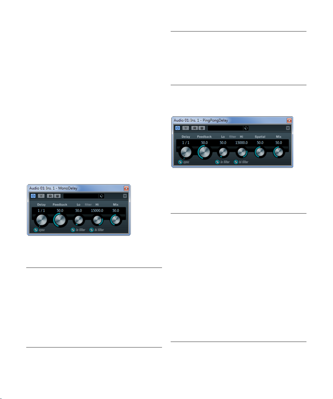
Filter Hi This filter affects the feedback loop of the effect signal
Mix Sets the level balance between the dry and the wet sig-
and allows you to roll off high frequencies from 20
down to 1.2
deactivates the filter.
nal. If MonoDelay is used as a send effect, set this to the
maximum value as you can control the dry/effect balance
with the send.
kHz. The button below the knob activates/
kHz
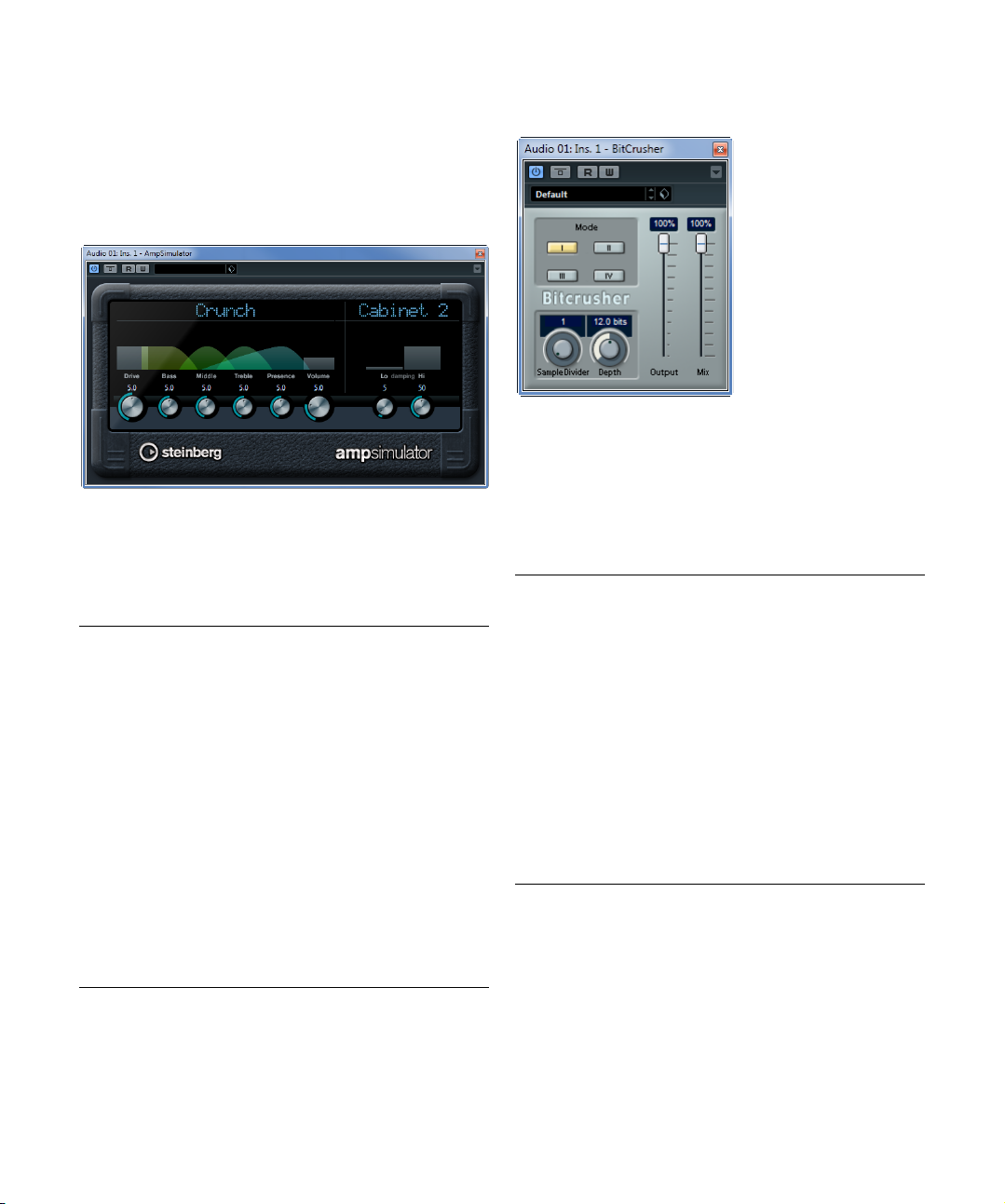
PingPongDelay (Cubase Elements only)
MonoDelay
This is a mono delay effect that can either be tempobased or use freely specified delay time settings.
The following parameters are available:
Parameter Description
Delay If tempo sync is on, this is where you specify the base
Sync button The button below the Delay knob is used to switch tempo
Feedback Sets the number of repeats for the delay.
Filter Lo This filter affects the feedback loop of the effect signal
note value for the delay (1/1–1/32, straight, triplet, or
dotted).
If tempo sync is off, the delay time can be set freely in
milliseconds.
sync on or off.
and allows you to roll off low frequencies from 10
Hz. The button below the knob activates/deactivates
800
the filter.
Hz up to
This is a stereo delay effect that alternates each delay repeat between the left and right channels. The effect can
either be tempo-based or use freely specified delay time
settings.
The following parameters are available:
Parameter Description
Delay If tempo sync is on, this is where you specify the base
Sync button The button below the Delay Time knob is used to switch
Feedback Sets the number of repeats for the delay.
Filter Lo This filter affects the feedback loop and allows you to roll
Filter Hi This filter affects the feedback loop and allows you to roll
Spatial Sets the stereo width for the left/right repeats. Turn clock-
Mix Sets the level balance between the dry and the wet sig-
note value for the delay (1/1–1/32, straight, triplet, or
dotted).
If tempo sync is off, the delay time can be set freely in
milliseconds.
tempo sync on or off.
off low frequencies up to 800
knob activates/deactivates the filter.
off high frequencies from 20
button below the knob activates/deactivates the filter.
wise for a more pronounced stereo “ping-pong” effect.
nal. If PingPongDelay is used as a send effect, set this to
the maximum value as you can control the dry/effect bal
ance with the send.
Hz. The button below the
kHz down to 1.2 kHz. The
-
The included effect plug-ins
6
Page 7
Distortion plug-ins
This section contains descriptions of the plug-ins in the
“Distortion” category.
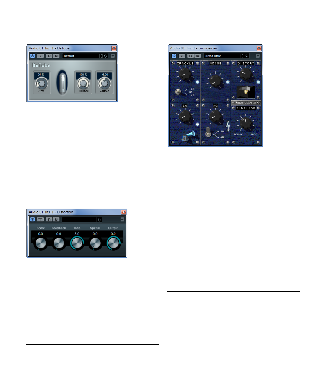
AmpSimulator
AmpSimulator is a distortion effect, emulating the sound
of various types of guitar amp and speaker cabinet combinations. A wide selection of amp and cabinet models is
available.
The following parameters are available:
Parameter Description
Amplifier
pop-up menu
Drive Controls the amount of amp overdrive.
Bass Tone control for the low frequencies.
Middle Tone control for the mid frequencies.
Treble Tone control for the high frequencies.
Presence Boosts or dampens the higher frequencies.
Volume Controls the overall output level.
Cabinet
pop-up menu
Damping Lo/Hi Further tone controls for shaping the sound of the se-
This pop-up menu is opened by clicking on the amplifier
name shown at the top of the amp section. It allows you
to select an amplifier model. The amp section can be by
passed by selecting “No Amp”.
This pop-up menu is opened by clicking on the cabinet
name shown at the top of the cabinet section. It allows
you to select a speaker cabinet model. This section can
be bypassed by selecting “No Speaker”.
lected speaker cabinet. Click on the values, enter a new
value and press the [Enter] key.
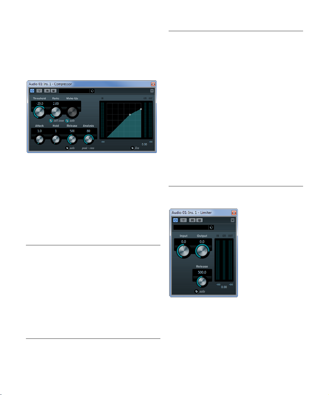
BitCrusher
If you are into lo-fi sound, BitCrusher is the effect for you.
It offers the possibility of decimating and truncating the in
put audio signal by bit reduction, to get a noisy, distorted
sound. You can for example make a 24-bit audio signal
sound like an 8 or 4-bit signal, or even render it completely
garbled and unrecognizable.
The following parameters are available:
Parameter Description
Mode Allows you to select one of the four operating modes of
Sample Divider Sets the amount by which the audio samples are deci-
-
Depth Defines the bit resolution. A setting of 24 gives the highest
Output slider Governs the output level from BitCrusher. Drag the slider
Mix slider Regulates the balance between the output from Bit-
BitCrusher. In each mode the plug-in sounds differently.
Modes I and III are nastier and noisier, while modes II and
IV are more subtle.
mated. At the highest setting (65), nearly all of the information describing the original audio signal is eliminated,
turning the signal into unrecognizable noise.
audio quality, while a setting of 1 creates mostly noise.
upwards to increase the level.
Crusher and the original audio signal. Drag the slider upwards for a more dominant effect, and downwards if you
want the original signal to be more prominent.
-
The included effect plug-ins
7
Page 8
DaTube (not in Cubase LE)
This effect emulates the characteristic warm, lush sound
of a tube amplifier.
The following parameters are available:
Parameter Description
Drive Regulates the pre-gain of the “amplifier”. Use high values
Balance Controls the balance between the signal processed by
Output Adjusts the post-gain, or output level, of the “amplifier”.
if you want an overdriven sound just on the verge of
distortion.
the Drive parameter and the dry input signal. For maxi
mum drive effect, set this to its highest value.
-
Distortion
Distortion will add crunch to your tracks.
The following parameters are available:
Parameter Description
Boost Increases the distortion amount.
Feedback Feeds part of the output signal back to the effect input,
Tone Lets you select a frequency range to which to apply the
Spatial Changes the distortion characteristics of the left and right
Output Raises or lowers the signal going out of the effect.
increasing the distortion effect.
distortion effect.
channel, thus creating a stereo effect.
Grungelizer
Grungelizer adds noise and static to your recordings –
kind of like listening to a radio with bad reception, or a
worn and scratched vinyl record. The following parame
ters are available:
Parameter Description
Crackle Adds crackle to create that old vinyl record sound. The
RPM switch When emulating the sound of a vinyl record, this switch
Noise Regulates the amount of static noise added.
Distort Adds distortion.
EQ Turn this knob to the right to cut off the low frequencies,
AC Emulates a constant, low hum of AC current.
Frequency
switch
Timeline Regulates the amount of overall effect. The farther to the
farther to the right you turn the knob, the more crackle is
added.
lets you set the RPM (revolutions per minute) speed of
the record (33/45/78 RPM).
and create a more hollow, lo-fi sound.
Sets the frequency of the AC current (50 or 60 Hz), and
thus the pitch of the AC hum.
right (1900) you turn the knob, the more noticeable the
effect.
-
The included effect plug-ins
8
Page 9
Dynamics plug-ins
This section contains descriptions of the plug-ins in the
“Dynamics” category.
Compressor (Cubase Elements only)
Compressor reduces the dynamic range of the audio, making softer sounds louder or louder sounds softer, or both.
Compressor features separate controls for threshold, ratio,
attack, hold, release and make-up gain parameters. Com
pressor features a separate display that graphically illustrates the compressor curve shaped according to the
Threshold and Ratio parameter settings. Compressor also
features a Gain Reduction meter that shows the amount of
gain reduction in dB, Soft knee/Hard knee compression
modes and a program-dependent Auto feature for the Re
lease parameter.
The following parameters are available:
Parameter Description
Threshold
(-60 to 0 dB)
Ratio
(1:1 to 8:1)
Soft Knee
button
Make-up
(0 to 24 dB or
Auto mode)
Determines the level where Compressor “kicks in”. Signal
levels above the set threshold are affected, but signal lev
els below are not processed.
Sets the amount of gain reduction applied to signals over
the set threshold. A ratio of 3:1 means that for every 3
the input level increases, the output level will increase by
only 1
dB.
If this button is off, signals above the threshold are compressed instantly according to the set ratio (hard knee).
When Soft Knee is activated, the onset of compression is
more gradual, producing a less drastic result.
This parameter is used to compensate for output gain loss,
caused by compression. If the Auto button is activated, the
knob becomes dark and the output is automatically ad
justed for gain loss.
-
dB
-
Parameter Description
Attack
(0.1 to
ms)
100
Hold
(0 to
5000
ms)
Release
(10 to
1000
ms or
Auto mode)
Analysis
(0 to 100)
(Pure Peak to
Pure RMS)
Live button When this button is activated, the “look ahead” feature of
Determines how fast Compressor will respond to signals
above the set threshold. If the attack time is long, more of
the early part of the signal (attack) passes through unpro
cessed.
Sets the time the applied compression will affect the signal
after exceeding the threshold.
Short hold times are useful for “DJ-style” ducking, while
longer hold times are required for music ducking, e.
when working on a documentary film.
Sets the amount of time it takes for the gain to return to its
original level when the signal drops below the threshold
level. If the Auto button is activated, Compressor will auto
matically find an optimal release setting that varies depending on the audio material.
Determines whether the input signal is analyzed according
to peak or RMS values (or a mixture of both). A value of 0 is
pure peak and 100 pure RMS. RMS mode operates using
the average power of the audio signal as a basis, whereas
Peak mode operates more on peak levels. As a general
guideline, RMS mode works better on material with few
transients such as vocals, and Peak mode better for per
cussive material, with a lot of transient peaks.
Compressor is disengaged. Look ahead produces more
accurate processing, but adds a certain amount of latency
as a trade-off. When Live mode is activated, there is no la
tency, which might be better for “live” processing.
Limiter (not in Cubase LE)
-
-
Limiter is designed to ensure that the output level never
exceeds a set output level, to avoid clipping in following
devices. Limiter can adjust and optimize the Release pa
rameter automatically according to the audio material, or it
can be set manually. Limiter also features separate meters
for the input, output and the amount of limiting (middle
meters).
-
g.
-
-
-
-
The included effect plug-ins
9
Page 10
The following parameters are available:
Limiter
Module Configuration
Gate
Compressor
Parameter Description
Input
(-24 to +24 dB)
Output
(-24 to +6 dB)
Release
(0.1 to 1000 ms
or Auto mode)
Allows you to adjust the input gain.
Determines the maximum output level.
Sets the amount of time it takes for the gain to return to
its original level. If the Auto button is activated, Limiter
will automatically find an optimal release setting that var
ies depending on the audio material.
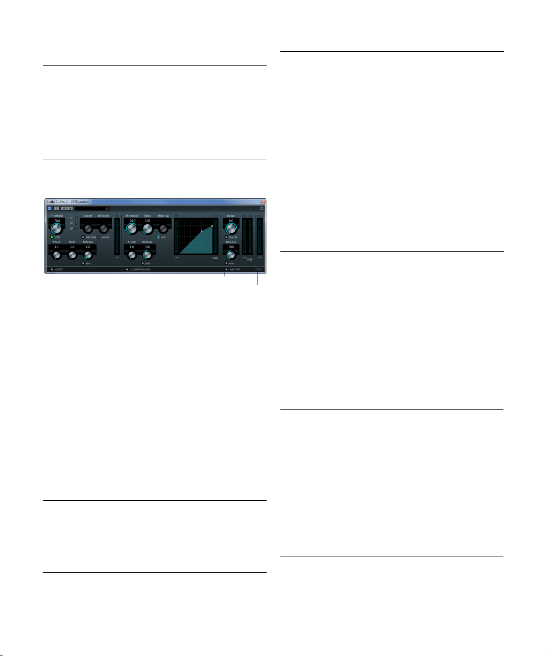
VSTDynamics
VSTDynamics is an advanced dynamics processor. It
combines three separate processors: Gate, Compressor
and Limiter, covering a variety of dynamic processing
functions. The window is divided into three sections, con
taining controls and meters for each processor.
Activating the individual processors
You activate the individual processors using the buttons
at the bottom of the plug-in panel.
The Gate section
Gating, or noise gating, is a method of dynamic processing that silences audio signals below a set threshold level.
As soon as the signal level exceeds the set threshold, the
gate opens to let the signal through.
The following parameters are available:
Parameter Description
Threshold
(-60 to 0 dB)
State LED Indicates whether the gate is open (LED lights up in
Determines the level where Gate is activated. Signal levels above the set threshold trigger the gate to open, and
signal levels below the set threshold close the gate.
green), closed (LED lights up in red) or something in be
tween (LED lights up in yellow).
Parameter Description
LP (low-pass),
BP (band-pass),
HP (high-pass)
Center (50 to
Hz)
22000
Q-Factor (0.001
to 10000)
Monitor
(On/Off)
Attack
(0.1 to 100 ms)
Hold
(0 to 2000 ms)
Release
(10 to 1000 ms
or Auto mode)
Input gain meter Shows the input gain.
These buttons set the basic filter mode.
Sets the center frequency of the filter.
Sets the resonance or width of the filter.
Allows you to monitor the filtered signal.
Sets the time it takes for the gate to open after being
triggered.
Determines how long the gate stays open after the signal drops below the threshold level.
Sets the amount of time it takes for the gate to close (after the set hold time). If the Auto button is activated,
Gate will find an optimal release setting, depending on
the audio material.
The Compressor section
The compressor reduces the dynamic range of the audio,
making softer sounds louder or louder sounds softer, or
both. It works like a standard compressor with separate
controls for threshold, ratio, attack, release and make-up
gain. The compressor features a separate display that
graphically illustrates the compressor curve shaped ac
cording to the Threshold, Ratio and Make-Up Gain pa-
rameter settings. It also features meters for input gain and
gain reduction and a program-dependent Auto feature for
the Release parameter.
The available parameters work as follows:
Parameter Description
Threshold
(-60 to 0 dB)
Ratio
(1:1 to 8:1)
Make-Up
(0 to 24 dB)
Attack
(0.1 to 100 ms)
-
Determines the level where the compressor “kicks in”.
Signal levels above the set threshold are affected, but
signal levels below are not processed.
Determines the amount of gain reduction applied to signals above the set threshold. A ratio of 3:1 means that for
every 3
dB the input level increases, the output level in-
creases by only 1 dB.
This parameter is used to compensate for output gain
loss, caused by compression. When the Auto button is
activated, gain loss is being compensated automatically.
Determines how fast the compressor responds to signals
above the set threshold. If the attack time is long, more of
the early part of the signal (attack) passes through un
processed.
-
-
The included effect plug-ins
10
Page 11
Parameter Description
Release
(10 to 1000 ms
or Auto mode)
Graphical
display
Sets the amount of time it takes for the gain to return to
its original level when the signal drops below the thresh
old level. If the Auto button is activated, the compressor
will automatically find an optimal release setting that var
ies depending on the audio material.
Use the graphical display to graphically set the Threshold
and Ratio values. To the left and right of the graphical dis
play you will find two meters that show the amount of input gain and gain reduction in dB.
The Limiter section
The limiter is designed to ensure that the output level
never exceeds a set threshold, to avoid clipping in follow
ing devices. Conventional limiters usually require very accurate setting up of the attack and release parameters to
prevent the output level from going beyond the set thresh
old level. The limiter adjusts and optimizes these parameters automatically according to the audio material. You
can also adjust the Release parameter manually.
The following parameters are available:
Parameter Description
Output
(-24 to +6 dB)
Soft Clip
button
Release
(10 to 1000 ms
or Auto mode)
Meters The three meters show the input gain (IN), the gain re-
Determines the maximum output level. Signal levels
above the set threshold are affected, but signal levels be
low are left unaffected.
If this button is activated, the limiter acts differently.
When the signal level exceeds -6
iting (or clipping) the signal “softly”, at the same time
generating harmonics which add a warm, tube-like char
acteristic to the audio material.
Sets the amount of time it takes for the gain to return to
its original level when the signal drops below the thresh
old level. If the Auto button is activated, the limiter will automatically find an optimal release setting that varies
depending on the audio material.
duction (GR) and the output gain (OUT).
dB, Soft Clip starts lim-
The Module Configuration button
Using the Module Configuration button in the bottom right
corner of the plug-in panel, you can set the signal flow or
der for the three processors. Changing the order of the
processors can produce different results, and the avail
-
able options allow you to quickly compare what works
best for a given situation. Simply click the Module Config-
-
uration button to change to a different configuration. There
are three routing options:
-
• C-G-L (Compressor-Gate-Limit)
• G-C-L (Gate-Compressor-Limit)
-
• C-L-G (Compressor-Limit-Gate)
Filter plug-ins
This section contains descriptions of the plug-ins in the
“Filter” category.
-
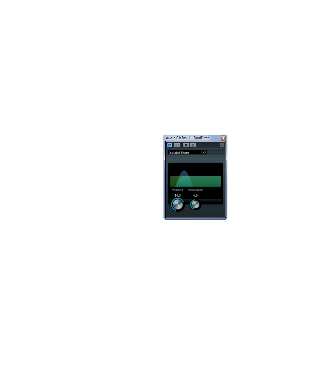
DualFilter
-
-
-
-
The DualFilter effect filters out certain frequencies while
allowing others to pass through.
The following parameters are available:
Parameter Description
Position Sets the filter cutoff frequency. If you set this to a nega-
Resonance Sets the sound characteristic of the filter. With higher val-
-
tive value, DualFilter will act as a low-pass filter. Positive
values cause DualFilter to act as a high-pass filter.
ues, a ringing sound is heard.
The included effect plug-ins
11
Page 12
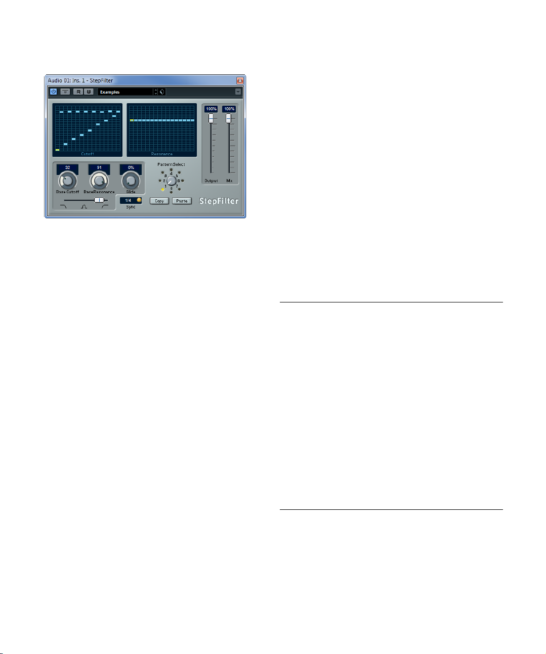
StepFilter (Cubase Elements only)
StepFilter is a pattern-controlled multimode filter that can
create rhythmic, pulsating filter effects.
General operation
StepFilter can produce two simultaneous 16-step patterns for the filter cutoff and resonance parameters, synchronized to the sequencer tempo.
Setting step values
• Setting step values is done by clicking in the pattern
grid windows.
• Individual step entries can be freely dragged up or
down the vertical axis, or directly set by clicking in an
empty grid box. By click-dragging left or right, consecutive
step entries are set at the pointer position.
• The horizontal axis shows the pattern steps 1 to 16 from
left to right, and the vertical axis determines the (relative)
filter cutoff frequency and resonance settings.
The higher up on the vertical axis a step value is entered, the higher the
relative filter cutoff frequency or filter resonance setting.
• By starting playback and editing the patterns for the
cutoff and resonance parameters, you can hear how your
filter patterns affect the sound source connected to StepFilter.
Selecting new patterns
• Created patterns are saved with the project, and up to 8
different cutoff and resonance patterns can be saved internally.
Both the cutoff and resonance settings are saved together in the 8 pattern slots.
• Use the Pattern Selector below the Resonance grid to
select a new pattern.
New patterns are all set to the same step value by default.
Using pattern copy and paste to create variations
You can use the Copy and Paste buttons below the Pattern Selector to copy a pattern to another pattern slot,
which is useful for creating variations on a pattern.
• Select the pattern you wish to copy, click the Copy button, select another pattern slot, and click Paste.
The pattern is copied to the new slot, and can now be edited to create
variations using the original pattern as a starting point.
StepFilter parameters
The following parameters are available:
Parameter Description
Base Cutoff Sets the base filter cutoff frequency. Values set in the
Base Resonance Sets the base filter resonance. Values set in the Reso-
Glide This will apply glide between the pattern step values,
Filter mode Use this slider to select a filter mode: low-pass (LP),
Sync button When the Sync button to the right of the Sync pop-up
Sync pop-up
menu (1/1 to
1/32, straight,
triplet, or dotted)
Output slider Sets the overall volume.
Mix slider Adjusts the mix between dry and processed signal.
Cutoff grid are relative to the Base Cutoff value.
nance grid are relative to the Base Resonance value.
Note that very high Base Resonance settings can pro
duce loud ringing effects at certain frequencies.
causing values to change more smoothly.
band-pass (BP), or high-pass (HP) (from left to right).
menu is activated (yellow), the pattern playback is syn
chronized with the project tempo.
Use this pop-up menu to set the pattern beat resolution, i. e. what note values the pattern will play in relation
to the tempo.
-
-
The included effect plug-ins
12
Page 13
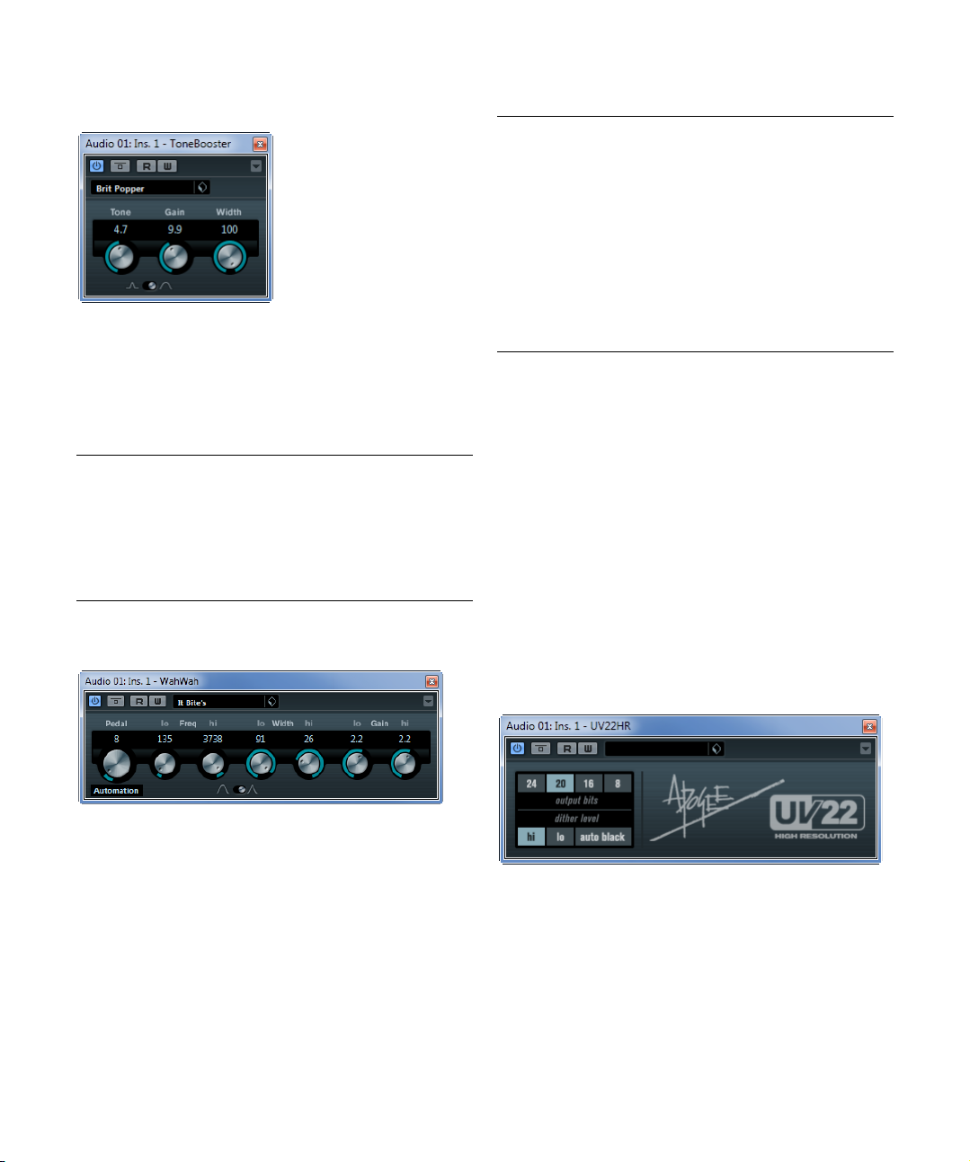
ToneBooster (not in Cubase LE)
ToneBooster is a filter that allows you to raise the gain in a
selected frequency range. It is particularly useful when
inserted before AmpSimulator in the plug-in chain (see
“AmpSimulator” on page 7), greatly enhancing the tonal
varieties available.
The following parameters are available:
Parameter Description
Tone Sets the center filter frequency.
Gain Allows you to adjust the gain of the selected frequency
Width Sets the resonance of the filter.
Mode
selector
range by up to 24
Sets the basic operational mode of the filter; Peak or Band
Mode.
dB.
WahWah (not in Cubase LE)
The following parameters are available:
Parameter Description
Pedal Controls the filter frequency sweep.
Pedal Control
(MIDI) pop-up
menu
Freq Lo/Hi Set the frequency of the filter for the Lo and Hi Pedal
Width Lo/Hi Set the width (resonance) of the filter for the Lo and Hi
Gain Lo/Hi Set the gain of the filter for the Lo and Hi Pedal positions.
Filter Slope
selector
Allows you to choose the MIDI controller that is used to
control the plug-in. Set this to “Automation” if you do not
want to use MIDI realtime control.
positions.
Pedal positions.
Allows you to choose between two filter slope values:
dB or 12 dB.
6
MIDI control
For realtime MIDI control of the Pedal parameter, MIDI
must be directed to the WahWah plug-in.
• Whenever WahWah has been added as an insert effect
(for an audio track or an FX channel), it is available on the
Output Routing pop-up menu for MIDI tracks.
If WahWah is selected on the Output Routing menu, MIDI data is directed to the plug-in from the selected track.
Mastering plug-ins
This section contains descriptions of the plug-ins in the
“Mastering” category.
WahWah is a variable slope band-pass filter that can be
auto-controlled via MIDI modeling the well-known analog
pedal effect (see below). You can independently specify
the frequency, width and the gain for the Lo and Hi Pedal
positions. The crossover point between the Lo and Hi
Pedal positions lies at 50.
The included effect plug-ins
UV22HR (Cubase Elements only)
The UV22HR is a dithering plug-in, based on an advanced
algorithm developed by Apogee. For an introduction to the
concept of dithering, see the chapter “Audio effects” in
the Operation Manual.
13
Page 14

The following parameters are available:
!
Option Description
Bit Resolution The UV22HR supports dithering to multiple resolutions:
Hi Try this first, it is the most “all-round” setting.
Lo This applies a lower level of dither noise.
Auto black When this is activated, the dither noise is gated (muted)
8, 16, 20 or 24 bits. You select the desired resolution by
clicking the corresponding button.
during silent passages in the material.
Dithering should always be applied post-fader on an
output bus.
Modulation plug-ins
This section contains descriptions of the plug-ins in the
“Modulation” category.
AutoPan
This is a simple auto-pan effect. It can use different waveforms to modulate the left-right stereo position (pan), either using tempo sync or manual modulation speed
settings.
The following parameters are available:
Parameter Description
Rate If tempo sync is on, this is where you specify the base
Sync button The button below the Rate knob is used to switch tempo
Width Sets the depth of the auto-pan effect.
Waveform
Shape selector
note value for tempo-syncing the effect (1/1 to 1/32,
straight, triplet, or dotted).
If tempo sync is off, the auto-pan speed can be set freely
with the Rate knob.
sync on or off.
Allows you to select the modulation waveform. A sine and
a triangle waveform are available.
Chopper
Chopper is a combined tremolo and autopan effect. It can
use different waveforms to modulate the level (tremolo) or
left-right stereo position (pan), either using tempo sync or
manual modulation speed settings.
The following parameters are available:
Parameter Description
Waveform
buttons
Depth Sets the depth of the Chopper effect. This can also be
Speed If tempo sync is on, this is where you specify the base
Sync button The button above the Speed knob is used to switch
Stereo/Mono
button
Mix Sets the level balance between the dry and the wet sig-
Set the modulation waveform.
set by clicking in the graphical display.
note value for tempo-syncing the effect (1/1 to 1/32,
straight, triplet, or dotted). Note that there is no note
value modifier for this effect.
If tempo sync is off, the tremolo/auto-pan speed can be
set freely with the Speed knob.
tempo sync on (button lights up) or off.
Determines whether the Chopper works as an auto-panner (button set to “Stereo”) or a tremolo effect (button set
to “Mono”).
nal. If Chopper is used as a send effect, this should be
set to the maximum value.
The included effect plug-ins
14
Page 15

Chorus
This is a single-stage chorus effect. It works by doubling
whatever is sent into it with a slightly detuned version.
The following parameters are available:
Parameter Description
Rate If tempo sync is on, this is where you specify the base
Sync button The button below the Rate knob is used to switch tempo
Width Determines the depth of the chorus effect. Higher set-
Waveform
Shape selector
Spatial Sets the stereo width of the effect. Turn clockwise for a
Mix Sets the level balance between the dry and the wet sig-
Delay Affects the frequency range of the modulation sweep by
Filter Lo/Hi Allow you to roll off low and high frequencies of the effect
note value for tempo-syncing the chorus sweep (1/1 to
1/32, straight, triplet, or dotted).
If tempo sync is off, the sweep rate can be set freely with
the Rate knob.
sync on or off.
tings produce a more pronounced effect.
Allows you to select the modulation waveform, altering
the character of the chorus sweep. A sine and a triangle
waveform are available.
wider stereo effect.
nal. If Chorus is used as a send effect, set this to the maximum value as you can control the dry/effect balance with
the send.
adjusting the initial delay time.
signal.
Flanger
Flanger is a classic flanger effect with added stereo
enhancement.
The following parameters are available:
Parameter Description
Rate If tempo sync is on, this is where you specify the base
Sync button The button below the Rate knob is used to switch tempo
Range Lo/Hi Set the frequency boundaries for the flanger sweep.
Feedback Determines the character of the flanger effect. Higher
Spatial Sets the stereo width of the effect. Turn clockwise for a
Mix Sets the level balance between the dry and the wet sig-
Waveform
Shape selector
Delay Affects the frequency range of the modulation sweep by
Manual knob Allows you to change the sweep position manually when
Manual button Use this button to activate/deactivate the Manual func-
Filter Lo/Hi Allow you to roll off low and high frequencies of the effect
note value for tempo-syncing the flanger sweep (1/1 to
1/32, straight, triplet, or dotted).
If tempo sync is off, the sweep rate can be set freely with
the Rate knob.
sync on or off.
settings produce a more “metallic” sounding sweep.
wider stereo effect.
nal. If Flanger is used as a send effect, set this to the maximum value as you can control the dry/effect balance with
the send.
Allows you to select the modulation waveform, altering
the character of the flanger sweep. A sine and a triangle
waveform are available.
adjusting the initial delay time.
the Manual button is deactivated. The value range is from
0 to 100.
tion. If activated, the flanger sweep is static, i. e. no modulation takes place.
signal.
The included effect plug-ins
15
Page 16

Metalizer (not in Cubase LE)
Phaser
Metalizer feeds the audio signal through a variable frequency filter, with tempo sync or time modulation and
feedback control.
The following parameters are available:
Parameter Description
Feedback The higher the value, the more “metallic” the sound.
Sharpness Governs the character of the filter effect. The higher the
Tone Governs the feedback frequency. The effect of this will be
On button Turns filter modulation on and off. When turned off, Met-
Mono button When this is activated, the output of Metalizer is mono.
Speed If tempo sync is on, this is where you specify the base
Sync button The button above the Speed knob is used to switch
Output slider Sets the overall volume.
Mix slider Sets the level balance between the dry and the wet sig-
value, the narrower the affected frequency area, produc
ing a sharper sound and a more pronounced effect.
more noticeable with high Feedback settings.
alizer works as a static filter.
note value for tempo-syncing the effect (1/1 to 1/32,
straight, triplet, or dotted). Note that there is no note
value modifier for this effect.
If tempo sync is off, the modulation speed can be set
freely with the Speed knob.
tempo sync on (button lights up) or off.
nal. If Metalizer is used as a send effect, set this to the
maximum value as you can control the dry/effect balance
with the send.
Phaser produces the well-known “swooshing” phasing
effect with additional stereo enhancement.
The following parameters are available:
Parameter Description
Rate If tempo sync is on, this is where you specify the base
Sync button The button below the Rate knob is used to switch tempo
Width Determines the width of the modulation effect between
Feedback Determines the character of the phaser effect. Higher
Spatial When using multi-channel audio, the Spatial parameter
Mix Sets the level balance between the dry and the wet sig-
Manual knob Allows you to change the sweep position manually when
Manual button Use this button to activate/deactivate the Manual func-
Filter Lo/Hi Allow you to roll off low and high frequencies of the effect
note value for tempo-syncing the phaser sweep (1/1 to
1/32, straight, triplet, or dotted).
If tempo sync is off, the sweep rate can be set freely with
the Rate knob.
sync on or off.
higher and lower frequencies.
settings produce a more pronounced effect.
creates a 3-dimensional impression by delaying modula
tion in each channel.
nal. If Phaser is used as a send effect, set this to the maximum level as you can control the dry/effect balance with
the send.
the Manual button is deactivated. The value range is from
0 to 100.
tion. If activated, the flanger sweep is static, i. e. no modulation takes place.
signal.
-
The included effect plug-ins
16
Page 17
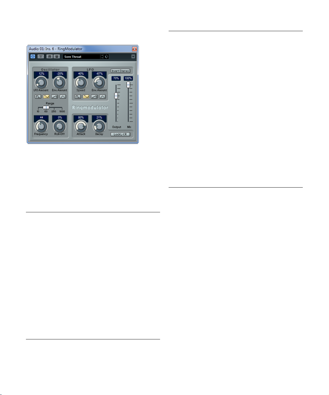
RingModulator (not in Cubase LE)
RingModulator can produce complex, bell-like enharmonic
sounds. Ring modulators work by multiplying two audio
signals. The ring modulated output contains added fre
quencies generated by the sum of, and the difference between, the frequencies of the two signals.
RingModulator has a built-in oscillator that is multiplied
with the input signal to produce the effect.
The following parameters are available:
Parameter Description
Oscillator –
LFO Amount
Oscillator –
Env. Amount
Oscillator –
Waveform
buttons
Oscillator –
Range slider
Oscillator –
Frequency
Oscillator –
Roll-Off
LFO – Speed Sets the LFO speed.
Controls how much the oscillator frequency is affected by
the LFO.
Controls how much the oscillator frequency is affected by
the envelope (which is triggered by the input signal). Pos
itive and negative values can be set, with center position
representing no modulation. Left of center, a loud input
signal will decrease the oscillator pitch, whereas right of
center the oscillator pitch will increase when fed a loud
input.
Allows you to select the oscillator waveform; square, sine,
saw, or triangle.
Determines the frequency range of the oscillator in Hz.
Sets the oscillator frequency +/- 2 octaves within the selected range.
Cuts high frequencies in the oscillator waveform, to
soften the overall sound. This is best used when harmon
ically rich waveforms are selected (e. g. square or saw).
-
Parameter Description
LFO –
Amount
Env.
LFO –
Waveform
LFO – Invert
Stereo
Envelope
Generator
section –
Attack and
Decay
Lock L<R
button
Output slider Sets the overall volume.
Mix slider Adjusts the mix between dry and processed signal.
-
-
Controls how much the input signal level – via the envelope generator – affects the LFO speed. Positive and
negative values can be set, at 0
plied. With negative values, a loud input signal slows
down the LFO, whereas positive values are used to
speed it up at loud input signals.
Allows you to select the LFO waveform; square, sine,
saw, or triangle.
Inverts the LFO waveform for the right channel of the oscillator, which produces a wider stereo perspective for
the modulation.
The Envelope Generator section controls how the input
signal is converted to envelope data, which can then be
used to control oscillator pitch and LFO speed. It has two
main controls:
Attack controls how fast the envelope output level rises in
response to a rising input signal.
Decay controls how fast the envelope output level falls in
response to a falling input signal.
When this button is enabled, the L and R input signals
are merged, and produce the same envelope output level
for both oscillator channels. When disabled, each chan
nel has its own envelope, which affects the two channels
of the oscillator independently.
% no modulation is ap-
-
The included effect plug-ins
17
Page 18

Rotary (Cubase Elements only)
The Rotary plug-in simulates the classic effect of a rotating speaker. A rotary speaker cabinet features speakers
rotating at variable speeds to produce a swirling chorus
effect, commonly used with organs. Rotary features all the
parameters associated with the real thing.
The following parameters are available:
Parameter Description
Speed selector
(Stop/Slow/
Fast)
Speed Change
Mode
Speed Mod When the Slow/Fast setting is set to variable control, this
MIDI controller
pop-up menu
Overdrive Applies a soft overdrive or distortion.
CrossOver Sets the crossover frequency (200 to 3000 Hz) between
Horn – Slow Allows for a fine adjustment of the high rotor Slow speed.
Horn – Fast Allows for a fine adjustment of the high rotor Fast speed.
Horn – Accel. Allows for a fine adjustment of the high rotor acceleration
Horn –
Mod
Amp
Horn –
Mod
Freq
Bass – Slow Allows for a fine adjustment of the low rotor Slow speed.
Bass – Fast Allows for a fine adjustment of the low rotor Fast speed.
Bass – Accel. Allows for a fine adjustment of the low rotor acceleration
Bass –
Mod
Amp
Allows you to control the speed of the Rotary in three
steps.
Allows you to select whether the Slow/Fast setting is a
switch (left) or a variable control (right). When switch
mode is selected and Pitchbend is the controller, the
speed will switch with an up or down flick of the bender.
Other controllers switch at MIDI value 64.
allows you to select the rotary speed, from 0 (Stop) to
100 (Fast).
Allows you to choose the MIDI controller that is used to
control the plug-in. Set this to “Automation” if you do not
want to use MIDI realtime control.
the low and high frequency loudspeakers.
time.
Controls the high rotor amplitude modulation.
Controls the high rotor frequency modulation.
time.
Adjusts the modulation depth of the amplitude.
Parameter Description
Bass – Level Adjusts the overall bass level.
Microphones –
Phase
Microphones –
Angle
Microphones –
Distance
Output Allows you to adjust the overall output level.
Mix Allows you to adjust the mix between dry and processed
Allows you to adjust the phasing amount in the sound of
the high rotor.
Sets the simulated microphone angle. 0 = mono,
= one mic on each side.
180
Sets the simulated microphone distance from the
speaker in inches.
signals.
Directing MIDI to the Rotary
For realtime MIDI control of the Speed parameter, MIDI
must be directed to the Rotary.
• Whenever Rotary has been added as an insert effect
(for an audio track or an FX channel), it is available on the
Output Routing pop-up menu for MIDI tracks.
If Rotary is selected on the Output Routing menu, MIDI is directed to the
plug-in from the selected track.
Tranceformer (not in Cubase LE)
Tranceformer is a ring modulator effect, in which the incoming audio is ring modulated by an internal, variable frequency oscillator, producing new harmonics. A second
oscillator can be used to modulate the frequency of the
first oscillator, in sync with the Song tempo if needed.
The included effect plug-ins
18
Page 19
The following parameters are available:
Parameter Description
Waveform
buttons
Tone Sets the frequency (pitch) of the modulating oscillator
Depth Governs the depth of the pitch modulation.
Speed If tempo sync is on, this is where you specify the base
Sync button The button above the Speed knob is used to switch
On button Turns modulation of the pitch parameter on or off.
Mono button Governs whether the output is stereo or mono.
Output slider Allows you to adjust the output level of the effect.
Mix slider Sets the level balance between the dry and the wet
Allow you to select a pitch modulation waveform.
to 5000 Hz).
(1
note value for tempo-syncing the effect (1/1 to 1/32,
straight, triplet, or dotted). Note that there is no note
value modifier for this effect.
If tempo sync is off, the modulation speed can be set
freely with the Speed knob.
tempo sync on (button lights up) or off.
signal.
Ö Note that clicking and dragging in the display allows
you to adjust the Tone and Depth parameters at the same
time!
Tremolo
Parameter Description
Spatial Adds a stereo effect to the modulation.
Output Allows you to adjust the output volume.
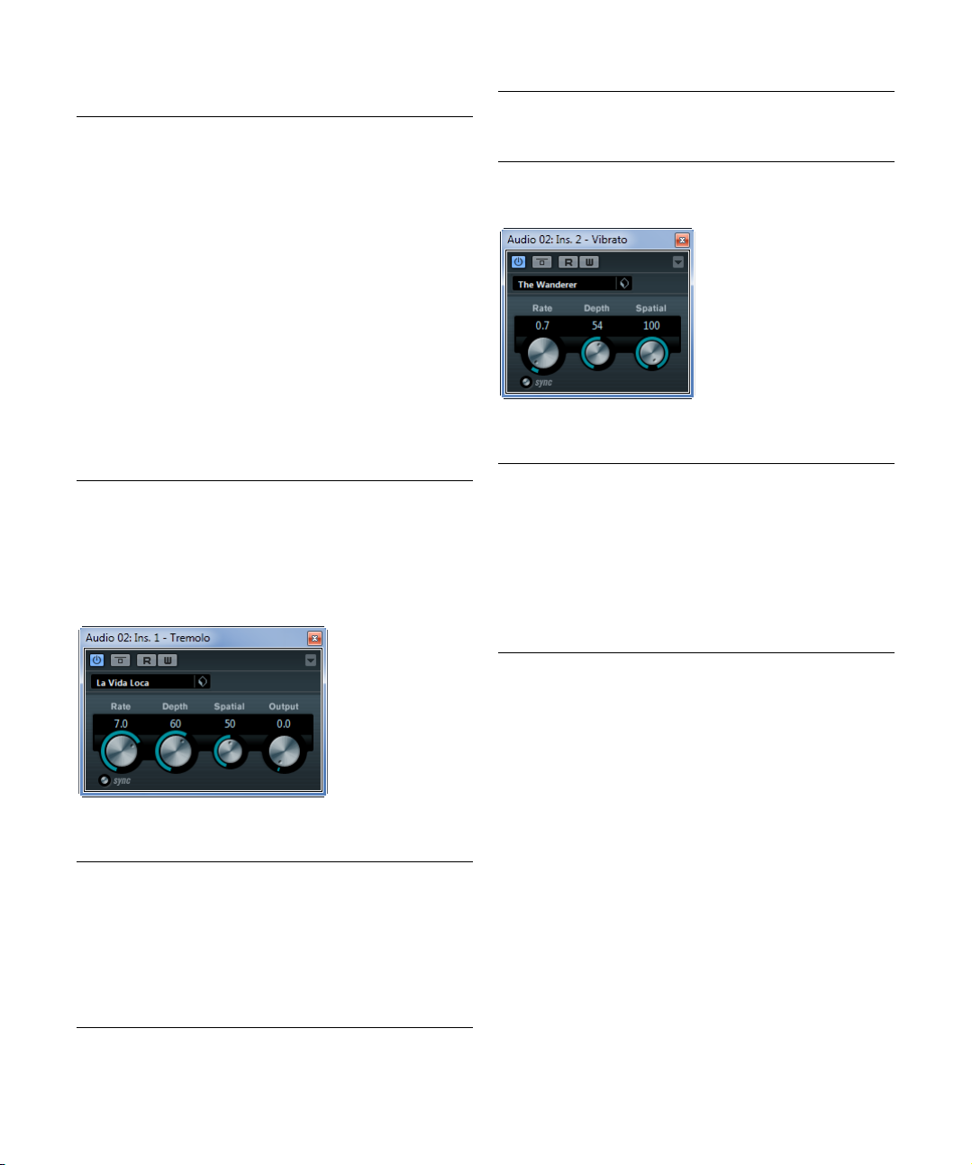
Vibrato
The Vibrato plug-in produces pitch modulation. The following parameters are available:
Parameter Description
Rate If tempo sync is on, this is where you specify the base
Sync button The button below the Rate knob is used to switch tempo
Depth Governs the depth of the pitch modulation.
Spatial Adds a stereo effect to the modulation.
note value for tempo-syncing the effect (1/1 to 1/32,
straight, triplet, or dotted).
If tempo sync is off, the modulation speed can be set
freely with the Rate knob.
sync on or off.
Tremolo produces amplitude (volume) modulation. The
following parameters are available:
Parameter Description
Rate If tempo sync is on, this is where you specify the base
Sync button The button below the Rate knob is used to switch tempo
Depth Governs the depth of the amplitude modulation.
note value for tempo-syncing the effect (1/1 to 1/32,
straight, triplet, or dotted).
If tempo sync is off, the modulation speed can be set
freely with the Rate knob.
sync on or off.
The included effect plug-ins
19
Page 20
Pitch Shift plug-ins
This section contains descriptions of the plug-ins in the
“Pitch Shift” category.
Octaver (not in Cubase LE)
This plug-in can generate two additional voices that track
the pitch of the input signal one octave and two octaves
below the original pitch, respectively. Octaver is best used
with monophonic signals.
The following parameters are available:
Parameter Description
Direct Adjusts the mix of the original signal and the generated
Octave 1 Adjusts the level of the signal that is generated one oc-
Octave 2 Adjusts the level of the signal that is generated two oc-
voices. A value of 0 means only the generated and trans
posed signal is heard. By raising this value, more of the
original signal is heard.
tave below the original pitch. A setting of 0 means that
the voice is muted.
taves below the original pitch. A setting of 0 means that
the voice is muted.
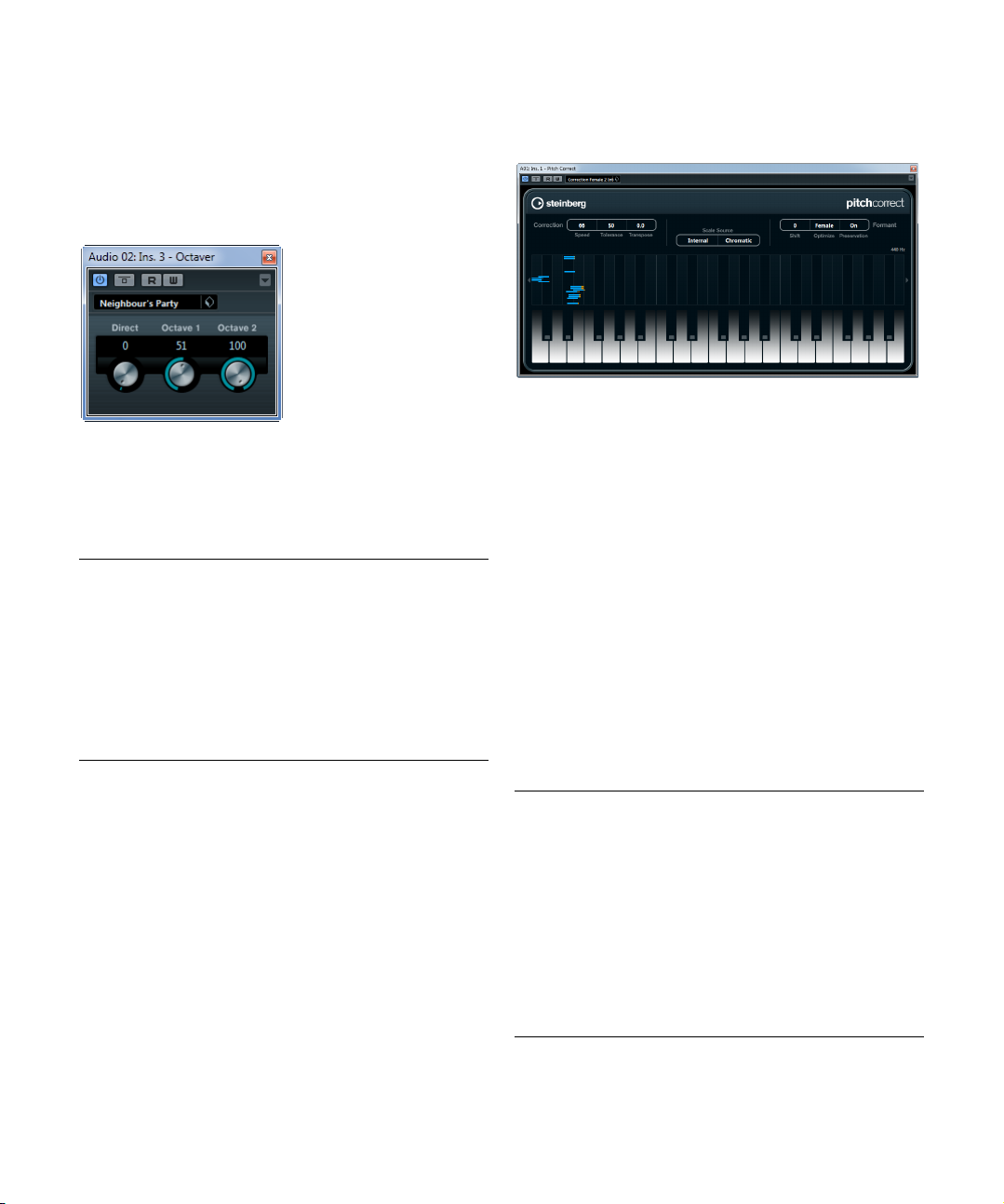
Pitch Correct
(Cubase
Pitch Correct automatically detects, adjusts and fixes
slight pitch and intonation inconsistencies in monophonic
vocal and instrumental performances in realtime. The advanced algorithms of this plug-in preserve the formants of
the original sound thus allowing for natural sounding pitch
correction without the typical “Mickey Mouse” effect.
Furthermore, you can use Pitch Correct creatively. You
can create backing vocals, for example, by modifying the
lead vocals or vocoder sounds by using extreme values.
You can use an external MIDI controller, a MIDI track or
-
the virtual keyboard to “play” a note or a scale of target
pitches that determine the current scale notes to which
the audio is shifted. This allows you to change your audio
in a very quick and easy way, which is extremely useful for
live performances. In the keyboard display, the original au
dio will be displayed in blue while the changes are displayed in orange.
The following parameters are available:
Parameter Description
Correction –
Speed
Correction –
Tolerance
Correction –
Transpose
(-12 to 12)
Elements only)
Determines the smoothness of the pitch change. Higher
values cause the pitch shift to occur immediately. 100 is
a very drastic setting that is designed mainly for special
g. the famous “Cher” effect).
effects (e.
Determines the sensitivity of analysis. A low Tolerance
value lets Pitch Correct find pitch changes quickly.
When the Tolerance value is high, pitch variations in the
audio (e.
g. vibrato) will not be immediately interpreted as
note changes.
With this parameter you can adjust (or “retune”) the pitch
of the incoming audio in semitone steps. You can set
positive and negative values from -12 to 12. A value of
zero means that the signal is not transposed.
-
The included effect plug-ins
20
Page 21

Parameter Description
Scale Source –
Internal
Scale Source –
External MIDI
Scale
Scale Source –
External MIDI
Note
Formant – Shift
(-60 to 60)
Formant –
Optimize
(General, Male,
Female)
Formant –
Preservation
(On/Off)
Master Tuning Detunes the output signal. The default setting is 440 Hz.
If you choose the Internal option from the Scale Source
pop-up menu, you can use the pop-up menu next to it to
decide to which scale the source audio will be adapted.
The following options are available:
Chromatic: The audio will be pitched to the closest semitone.
Major/Minor: The audio will be pitched to the major/minor scale specified in the pop-up menu to the right. This
will be reflected on the keyboard display.
Custom: The audio will be pitched to the notes that you
specify by clicking the desired keys on keyboard display.
To reset the keyboard, click on the orange line below the
display.
Select this option if you want the audio to be shifted to a
scale of target pitches, using an external MIDI controller,
the Virtual Keyboard or a MIDI track.
Note that you have to assign the audio track as the output of your MIDI track and that the Speed parameter has
to be set to a value other than Off.
Select this option if you want the audio to be shifted to a
target note, using an external MIDI controller, the Virtual
Keyboard or a MIDI track.
Note that you have to assign the audio track as the output of your MIDI track and that the Speed parameter has
to be set to a value other than Off.
Changes the natural timbre, i. e. the characteristic frequency components of the source audio.
Allows you to specify the sound characteristics of the
sound sources. While General is the default setting,
Male is designed for low pitches and Female for high
pitches.
When set to Off, formants are raised and lowered with
the pitch, provoking strange vocal effects. Higher pitch
correction values result in “Mickey Mouse” effects, lower
pitch correction values in “Monster” sounds.
When set to On, the formants are kept, maintaining the
character of the audio.
Reverb plug-ins
This section contains descriptions of the plug-ins in the
“Reverb” category.
RoomWorks SE
Roomworks SE is a high-quality reverb plug-in.
The following parameters are available:
Parameter Description
Pre-Delay Controls how much time passes before the reverb is ap-
Reverb Time Allows you to set the reverb time in seconds.
Diffusion Affects the character of the reverb tail. Higher values lead
Hi Level Affects the decay time of high frequencies. Normal room
Lo Level Affects the decay time of low frequencies. Normal room
Mix Determines the blend of dry (unprocessed) signal to wet
plied. This allows you to simulate larger spaces by increasing the time it takes for first reflections to reach the
listener.
to more diffusion and a smoother sound, while lower val
ues lead to a clearer sound.
reverb decays quicker in the high- and low-frequency
range than in the mid-range. Lowering the level percent
age causes high frequencies to decay quicker. Values
above 100
slowly than the mid-range frequencies.
reverb decays quicker in the high- and low-frequency
range than in the mid-range. Lowering the level percent
age causes low frequencies to decay quicker. Values
above 100
slowly than the mid-range frequencies.
(processed) signal. When using RoomWorks SE inserted
in an FX channel, you will most likely want to set this to
100
% cause high frequencies to decay more
% cause low frequencies to decay more
% or use the wet only button.
-
-
-
The included effect plug-ins
21
Page 22
Spatial + Panner plug-ins
This section contains descriptions of the plug-ins in the
“Spatial + Panner” category.
MonoToStereo (not in Cubase LE)
This effect will turn a mono signal into a “pseudo-stereo”
signal. The plug-in must be inserted on a stereo track
playing a mono file.
The following parameters are available:
Parameter Description
Width Controls the width or depth of the stereo enhancement.
Delay Increases the amount of differences between the left and
Color Generates additional differences between the channels
Mono button Switches the output to mono, to check for possible un-
Turn clockwise to increase the enhancement.
right channels to further increase the stereo effect.
to increase the stereo effect.
wanted coloring of the sound which sometimes can occur when creating an artificial stereo image.
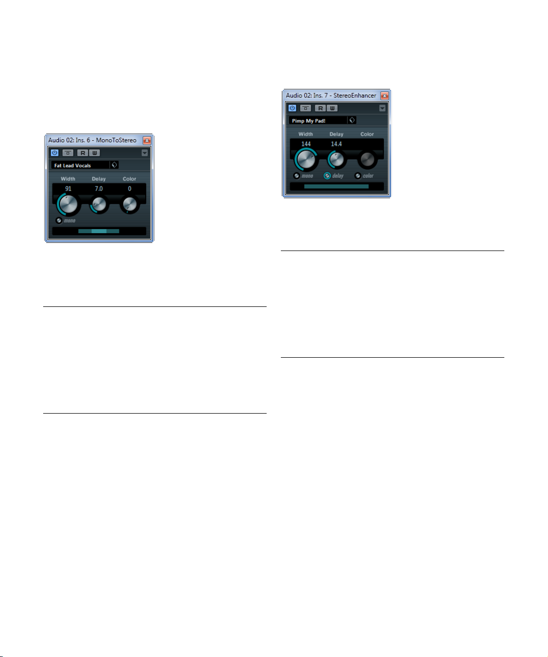
StereoEnhancer
(Cubase
This plug-in will expand the stereo width of (stereo) audio
material. It cannot be used with mono files.
The following parameters are available:
Parameter Description
Width Controls the width or depth of the stereo enhancement.
Delay Increases the amount of differences between the left and
Color Generates additional differences between the channels
Mono button Switches the output to mono, to check for possible un-
Elements only)
Turn clockwise to increase the enhancement.
right channels to further increase the stereo effect.
to increase the stereo enhancement.
wanted coloring of the sound which sometimes can occur when enhancing the stereo image.
The included effect plug-ins
22
Page 23
Tools plug-ins
This section describes the plug-ins in the “Tools” category.
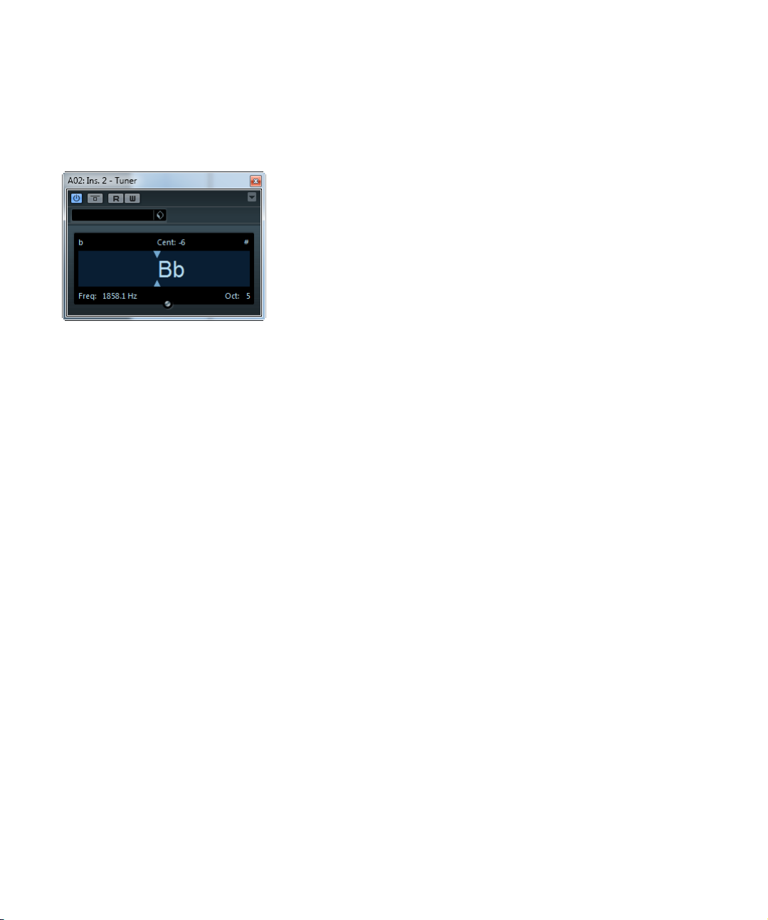
Tuner (not in Cubase LE)
This is a guitar tuner. Simply connect a guitar or other instrument to an audio input and select the Tuner as an insert effect (make sure you deactivate any other effect that
alters pitch, like chorus or vibrato).
When you play a note, the pitch is shown in the middle of
the display. In addition, the frequency in Hz is shown in the
bottom left corner and the octave range in the bottom right
corner.
The two arrows indicate any deviation in pitch. If the pitch
is flat, they are positioned in the left half of the display, if
the pitch is sharp they are in the right half. The deviation is
also shown (in Cent) in the upper area of the display.
• If a string is out of tune (e. g. if the pitch for the E string
is shown as Eb), tune the string so that the correct pitch is
shown and the two arrows are in the middle.
Repeat this procedure for each string.
• To mute the output signal so that you can tune the
strings in silence, activate the Mute button at the bottom
middle of the plug-in panel.
The included effect plug-ins
23
Page 24

2
The included VST instruments
Page 25

Introduction
This chapter contains descriptions of the included VST instruments and their parameters.
Groove Agent ONE (Cubase Elements only)
Groove Agent ONE is an easy-to-use sample-based
MPC-style virtual drum machine for creating beats and
reconstructing loops.
Audio samples can be associated with the Groove Agent
ONE pads. Each pad is associated with a MIDI pitch, allowing you to trigger individual pads via MIDI notes.
To facilitate the creation of your own drum patterns, Groove
Agent ONE provides a number of advanced functions.
Groups and pads
The pads and all functions related to the associating and
auditioning of sounds can be found in the right half of the
Groove Agent ONE panel.
Groove Agent ONE provides up to 128 pads, organized in
eight groups of 16 pads. You can switch between the dif
ferent groups by clicking on the corresponding group buttons (labeled 1 to 8) above the pads. Each pad is mapped
to a particular MIDI note (C-2 to G8, which equals 128
notes).
• The button of the active group is highlighted. If one or
more pads of a group have samples mapped to them, an
additional red frame is displayed around group buttons.
By default, group 3 is active when you open Groove Agent ONE.
Pad functions
• The pads show the associated MIDI note in the top right
corner.
You can change the MIDI note by right-clicking it and selecting a different note from the pop-up menu.
• You can assign up to eight samples to a pad.
See “Drag & drop of audio material” on page 26.
• If one or more samples have been assigned to a pad,
the name of the first of these samples is displayed at the
bottom of the pad.
To change the name, right-click it, enter a new name and press [Enter].
This allows you, e.
this pad.
g., to indicate that more than one sample is mapped to
• To remove a sample assignment, click on the pad and
drag the associated sample(s) to the trash icon in the
LCD display to the left (see “Editing sounds” on page 27).
Note that the trash icon is found only on either the Voice, Filter or Amplifier
pages.
• The pad status is indicated by different colors.
During playback, a pad lights up yellow for as long as a sample mapped
to this pad is played back. When either the Voice, Filter or Amplifier but
ton is activated in the Pad Edit section and you click on a pad, it turns
light green to indicate that it is selected for editing. Unselected pads not
playing back any samples are gray.
• To select multiple pads for sound editing, [Ctrl]/[Command]-click on the pads.
The pad that has been selected first lights up light green, the rest of the
selected pads turn dark green (see
“Editing sounds” on page 27).
• To mute or solo a pad, click the corresponding icon in
the upper left corner of a pad.
The icon lights up to indicate that the pad is muted or soloed. If you solo
a pad, all other pads are muted automatically. To unmute or unsolo the
pad, click once more on the icon.
• You can drag a sample from one pad to another pad.
If the second pad already has a sample mapped to it, the sample assignment is swapped. Note that you can also swap the MIDI notes of the two
-
pads by pressing [Shift] when dropping the sample.
• You can drag and drop samples between groups.
Click on a pad that has a sample mapped to it, keep the mouse button
pressed and move the mouse pointer over the button of another group.
When the pad display now changes to display the pads of the other
group, drag and drop the sample on the desired pad.
-
The included VST instruments
25
Page 26

Velocity
!
• The velocity is determined by where on the pad you
click: it is lowest at the bottom of the pad and highest at
the top.
• You can force all pads to a velocity value of 127 by activating the V-Max button in the Global section in the top
right corner of the Groove Agent ONE panel.
Resetting pads
You can find a Reset button in the Global section in the
top right corner of the Groove Agent ONE panel. It allows
you to clear all pad assignments of the current instance of
Groove Agent ONE.
As a safety precaution, the Reset button is locked by default. Clicking the Reset button when it is locked has no
effect.
To unlock the Reset button, hold down the [Shift] key
while clicking. The button color changes to red. When you
click Reset now, all pad assignments are reset.
The Reset button is re-locked automatically five seconds after unlocking it.
Drag & drop of audio material
Groove Agent ONE provides advanced drag & drop support. You can drag one or more samples at the same time
from Cubase onto Groove Agent ONE. Samples can either be mapped to the same pad, or to different pads.
You can drag files to Groove Agent ONE from the following Cubase locations:
•MediaBay
• Project window
•Pool
• Sample Editor (regions)
• Audio Part Editor
Layering samples on the same pad
When you select between one and eight samples and drag
them to Groove Agent ONE, dropping them onto a pad (or
onto the Layer indicator – see below) automatically creates
a corresponding number of layers for this pad.
Drag & drop to several pads
Rather than dropping several samples to the same pad,
you can also let Groove Agent ONE distribute samples
across the available pads in one or several groups. To do
so, select the desired samples, drag them to the Groove
Agent ONE window, press [Shift] and drop the samples
onto a pad. The samples are mapped to the available
pads, starting with the pad on which you initially dropped
the samples, and then upwards according to the MIDI
pitches of the pads.
How many samples can be dropped to several pads depends on the number of pads available in your current instance of Groove Agent ONE. If Groove Agent ONE
cannot supply a sufficient number of free pads for the
number of dropped samples, a dialog is displayed in
which you can confirm or cancel the operation.
Replacing individual samples
To replace a sample mapped to one pad with another
sample, proceed as follows:
• Drag the new sample to the pad, press [Alt]/[Option]
and drop it.
To replace a sample in a pad layer with another sample,
proceed as follows:
• Drag the new sample to the Layer indicator, press [Alt]/
[Option] and drop it onto the required layer.
Slicing a loop and triggering individual sounds via MIDI
Drag & drop to several pads has a number of uses. For example, it allows you to trigger individual sounds from an
audio loop via MIDI. Proceed as follows:
1. Slice up a drum loop using the Sample Editor. Open
the resulting audio part in the Audio Part Editor and press
[Ctrl]/[Command]-[A] to select all audio events.
See the Operation Manual for details about slicing.
2. In the Audio Part Editor, click on one of the selected
events and drag it to the Groove Agent ONE window.
3. Press the [Shift] key.
4. Point the mouse pointer at an empty pad and let go of
the mouse button.
The individual samples from the audio part are now mapped to the available pads of Groove Agent ONE.
The included VST instruments
26
Page 27

Now look at the Exchange section (to the left of the pads):
!
the MIDI Export pad (the field displaying a double arrow)
at the bottom of the section is lit. When mapping several
samples to several pads, Groove Agent ONE creates a
MIDI file containing all MIDI information to trigger these
pads, and maps this file to the MIDI Export pad.
5. Drag this MIDI file from the MIDI Export pad onto the
Cubase Project window.
Dropping the file onto the Project window creates a new MIDI track. You
can also drop the MIDI file to an existing MIDI or instrument track.
6. Play back the MIDI file.
The unedited MIDI file plays the same groove as the original audio loop.
By editing the MIDI file you can change the original groove.
Saving the Groove Agent ONE setup
You can save the current configuration of Groove Agent
ONE either as a plug-in preset or as a combination of a
Groove Agent ONE archive (.gak) and a plug-in preset.
These presets and archives are useful in cases where you
want to use your current settings and samples on a different computer.
Saving plug-in presets
You can save your current Groove Agent ONE configuration, including all settings for samples, pads and groups,
as a plug-in preset.
1. At the top of the Groove Agent ONE window, click the
VST Sound button to the right of the Presets pop-up
menu and select “Save Preset”.
The Save Preset dialog opens.
2. Enter a name for the new preset and click OK.
The preset is saved in the User Content folder on your system.
• When a sample belonging to a preset cannot be found,
Groove Agent ONE prompts you to locate the missing
files. You can click either Ignore to skip this message,
click Locate File to navigate to a specific folder containing
the missing file(s), or click Search Folder to browse a spe
cific folder and any subfolders that might contain the missing file(s).
Saving a GAK archive
You can save all Groove Agent ONE settings, and the
sample files referenced by the current configuration, as a
Groove Agent ONE kit. The file name extension of these
kit files is “*.gak”. Proceed as follows:
1. Set up Groove Agent ONE the way you want it.
2. In the Exchange section, click the Export button.
The “Export Groove Agent ONE kit” dialog opens in which you can specify a location and a name for the new archive.
3. Click Save.
The archive is created and the dialog is closed.
Note that a plug-in preset file is created alongside the
.gak file. This plug-in preset references the samples
inside the .gak file. It can be browsed in the MediaBay, giving you access to all Groove Agent ONE settings (including all samples) from within Cubase.
Loading a GAK archive
To load the GAK file, proceed as follows:
1. In the Exchange section, click the Import button.
Navigate to the GAK file.
2. Click Open.
The saved settings and all samples are imported into Groove Agent ONE.
Loading plug-in presets
To load an existing plug-in preset, proceed as follows:
1. At the top of the Groove Agent ONE window, click the
VST Sound button and select “Load Preset” from the
pop-up menu.
The Presets browser opens.
2. The Presets browser shows all presets it finds in the
VST 3 Presets folder for Groove Agent ONE. Double-click
the desired preset to load it.
The Presets browser is closed and the preset is loaded into Groove
Agent ONE.
The included VST instruments
Editing sounds
All sound editing functions can be found in and below the
LCD display in the left half of the panel.
The LCD display can show four different sound editing
pages, selected by clicking one of the four buttons in the
Pad Edit section.
The information on the Play page refers to this instance of
Groove Agent ONE as a whole. When the Play button is
activated, the LCD display shows the name of the loaded
VST preset and information on the number of samples and
27
Page 28

pads used by this instance of Groove Agent ONE. The
Size parameter indicates the amount of RAM occupied by
the currently loaded samples. The Polyphony counter
shows the number of pads currently playing.
• Click on a pad for sound editing.
It turns light green and the display shows its sample parameters.
• To adjust a parameter, either use one of the quick controls below the display, or click on the parameter in the
display and adjust it by dragging your mouse.
• You can select multiple pads for sound editing by [Ctrl]/
[Command]-clicking on them, and adjust their parameters
in one go with the quick controls below the display.
The first selected pad lights up light green, all other selected pads turn
dark green. The display shows the parameters of the first selected pad.
• By default, the parameters of the selected samples are
adjusted in relation to their previous settings. If you want
to set a specific value for all selected samples, [Ctrl]/
[Command]-click the quick control to set an initial value,
release [Ctrl]/[Command] and adjust the value.
The parameter will be set to the same value for all selected sample pads.
On the Voice, Filter, and Amplifier pages, sample-specific
data is displayed:
Parameter Description
Brightness
slider
VST Preset The name of a loaded VST Preset is displayed in the top
Sample/Pad The name of the sample (and the pad to which it is as-
Trash icon You can remove the current sample assignment by click-
MIDI input off When the MIDI symbol button in the top right corner of the
Layer indicator The long bar near the top of the LCD display shows the
Layer number The layer number indicates which is the active layer of the
Use the little slider at the very top of the LCD display to
set the display brightness.
left of the LCD display.
signed).
ing on a pad or on the Layer indicator (see below) and
dragging it onto the trash icon.
LCD display is activated, the LCD display shows the
waveform and parameter values of the currently playing
sample. When this button is deactivated, the display
shows only the data for the currently edit selected sample.
active layer for the current pad. If more than one layer ex
ist for the selected pad, the bar is divided accordingly.
You can drag the dividing line between layers to change
the velocity ranges of the layers. You can drag a new
sample from the MediaBay and drop it directly onto the
Layer indicator bar (this is the same as dropping a sample
on a pad). You can drag layers to a different position on
the bar.
current pad.
Parameter Description
Sample This is the name of the sample file.
Velocity Here you can specify a velocity range for the current
Coarse Here you can tune the sample by up to ±12 semitones.
Fine This parameter lets you fine-tune the sample by up to
Volume Sets the sample volume.
Waveform
display
s/e locators in
waveform
display
layer.
±100 cents.
The waveform of the current sample.
You can define the sample start and end points by dragging the s and e locators in the waveform display. When
you click on a locator and press [Ctrl], this will zoom in on
the waveform and center the display around the locator.
Note that the locators automatically snap to zero cross
ings.
Depending on the selected page (Play, Voice, Filter, Amplifier), up to six quick controls with different pad-specific
parameter assignments are displayed.
Play parameters
The parameter controls on the Play page are copies of the
parameters on the Voice, Filter, and Amplifier pages.
The row of parameter controls below the LCD display
shows six parameters:
Parameter Description
Volume The volume of the pad currently selected for editing.
Pan The panorama setting of the pad currently selected for
Coarse Use this control to tune the pad by up to ±12 semitones.
Cutoff Sets the filter cutoff frequency.
Q Sets the filter resonance.
Output Groove Agent ONE provides up to 16 stereo outputs. You
editing.
can route pads to individual outputs using this control.
Voice parameters
The row of parameter controls below the LCD display
-
shows six parameters:
Parameter Description
Mode Here you can reverse the currently selected sample so
Coarse Use this control to tune the pad by up to ±12 semitones.
Fine Use this control to fine-tune the pad by up to ±100
that you hear it backwards.
cents.
-
The included VST instruments
28
Page 29

Parameter Description
Mute Gr. With this control you can assign a pad to one of eight
Tr. Mode The sample of the currently selected pad is played either
Output Groove Agent ONE provides up to 16 stereo outputs.
mute groups. Pads within a mute group never play back
simultaneously. New notes cancel previous notes.
from start to finish (One Shot) or only for as long as you
hold the mouse button/key (Key Hold). Key Hold can also
be determined by the length of the corresponding MIDI
note on your track.
You can route pads to individual outputs using this con
trol. See the Operation Manual for information on how to
use multitimbral instruments in Cubase.
Filter parameters
The row of parameter controls below the LCD display
shows four parameters used to edit the Groove Agent
ONE filter:
Parameter Description
Type Sets the filter type: low-pass (LP), high-pass (HP) or band-
Cutoff Sets the filter cutoff frequency.
Q Sets the filter resonance.
Mod This parameter determines the influence that velocity has
pass (BP). When you set this knob to OFF, the settings on
this editing page have no effect.
on the cutoff frequency. When set to 0
no effect. When set to any other value, the cutoff fre
quency changes depending on the velocity.
%, the setting has
-
Amplifier parameters
The row of parameter controls below the LCD display
shows six parameters:
Parameter Description
Volume The volume of the pad currently selected for editing.
Pan The panorama setting of the pad currently selected for
Attack Controls the amplifier envelope attack time.
Release Controls the amplifier envelope release time. Reduce the
Amp Mod This parameter determines the influence that velocity has
Attack Mod This parameter determines the influence that velocity has
editing.
release time to shorten the decay of sounds played in
one-shot mode.
on the pad volume setting. When set to 100
sounds louder the higher the velocity. When set to 0
velocity has no effect on the pad volume.
on the Attack setting. When set to 0
effect on the attack. When set to 100
pad with high velocity, the Attack time is increased by
%. The higher the Attack Mod setting, the longer the
50
additional attack time for a pad.
%, the pad
%, velocity has no
% and playing a
%,
Master volume
In the Master section in the lower left of the Groove Agent
ONE panel you can find a master volume slider that sets
the output volume of the instrument.
The Exchange section
This section is used to import or export data to/from
Groove Agent ONE.
-
Importing MPC files
Clicking the Import button opens a file dialog in which you
can navigate to a PGM file (.pgm is the AKAI MPC ex
change format).
Ö Groove Agent ONE imports only the mapping data
from the PGM file. Any additional information (on MPC effects, etc.) cannot be imported into Groove Agent ONE.
The MIDI Export pad is described in detail in the section
“Slicing a loop and triggering individual sounds via MIDI”
on page 26.
The function of the Export button is described in detail in
the section
“Saving a GAK archive” on page 27.
Automation of Groove Agent ONE parameters
When opening an automation subtrack for a track that
uses Groove Agent ONE, you can select the following
plug-in parameters from the Add Parameters dialog:
•Volume
•Pan
•Mute
•Cutoff
• Resonance
These parameters are available for the pads C1 to B4.
-
The included VST instruments
29
Page 30

HALion Sonic SE
Sound parameters
This VST instrument is described in detail in the separate
PDF document “HALion Sonic SE”.
Prologue (Cubase Elements only)
Prologue is modelled on subtractive synthesis, the method
used in classic analog synthesizers. It has the following basic features:
• Multimode filter
Variable slope low pass and high pass, plus band pass and notch filter
modes – see
• Three oscillators, each with 4 standard waveforms plus
an assortment of specialized waveforms.
See “Selecting Waveforms” on page 30.
• Frequency modulation.
See “About frequency modulation” on page 32.
• Ring Modulation.
See “Ring modulation” on page 33.
• Built-in effects.
See “Effects (EFX) page” on page 38.
• Prologue receives MIDI in Omni mode (on all MIDI
channels).
You do not have to select a MIDI channel to direct MIDI to the Prologue.
“About the filter types” on page 34.
Oscillator section
This section contains parameters affecting the 3 oscillators.
These are located in upper half of the instrument panel.
Selecting Waveforms
Each oscillator has a number of waveforms which are selectable by clicking on the waveform name in the box located in each oscillator section.
The following waveforms are available:
Waveform Description
Sawtooth This waveform contains all harmonics and produces a
Parabolic This can be described as a “rounded” sawtooth wave-
Square Square waveforms only contain odd number harmonics,
Triangle The triangle waveform generates only a few harmonics,
bright and rich sound.
form, producing a softer timbre.
which produces a distinct, hollow sound.
spaced at odd harmonic numbers, which produces a
slightly hollow sound.
The included VST instruments
30
Page 31

Waveform Description
Sine The sine wave is the simplest possible waveform, with no
Formant 1–12 Formant waveforms emphasizes certain frequency bands.
Vocal 1–7 These are also formant waveforms, but specifically vocal-
Partial 1–7 Partials, also called harmonics or overtones, are a series
Reso Pulse
1–12
Slope 1–12 This waveform category begins with a complex waveform
Neg Slope
1–9
harmonics (overtones). The sine wave produces a neu
tral, soft timbre.
Like the human voice, musical instruments have a fixed
set of formants, which give it a unique, recognizable tonal
color or timbre, regardless of pitch.
oriented. Vowel sounds (A/E/I/O/U) are among the wave
forms found in this category.
of tones which accompany the prime tone (fundamental).
These waveforms can be described as producing inter
vals with two or more frequencies heard simultaneously
with equal strength.
This waveform category begins with a complex waveform
(Reso Pulse 1), that emphasizes the fundamental fre
quency (prime). For each consecutive waveform in this
category, the next harmonic in the harmonic series is
emphasized.
(Slope 1), with gradually decreasing harmonic complexity
the higher the number selected. Slope 12 produces a
sine wave (no harmonics).
This category also begins with a complex waveform
(NegSlope 1), but with gradually decreasing low fre
quency content the higher the number selected.
-
-
-
• To hear the signal generated by the oscillator(s), the
corresponding Osc controls in the oscillator sections
must be turned clockwise to a suitable value.
OSC 1 parameters
Oscillator 1 acts as a master oscillator. It determines the
base pitch for all three oscillators. Oscillator 1 features the
following parameters:
Parameter Description
Osc 1
(0–100)
Coarse
(±48
semitones)
Fine
(±50 cent)
This controls the output level of the oscillator.
This determines the base pitch used by all oscillators.
Fine tunes the oscillator pitch in cent increments (100th
of a semitone). This also affects all oscillators.
Parameter Description
-
-
Wave Mod
(±50)
Phase button
(On/Off)
Tracking
button
(On/Off)
Wave Mod
button
(On/Off)
Waveform
pop-up menu
(see “Selecting
Waveforms”
on page 30)
This parameter is only active if the Wave Mod button is
activated beside the waveform selection box. Wave mod
ulation works by adding a phase-shifted copy of the oscillator output to itself, which produces waveform
variations. For example if a sawtooth waveform is used,
activating WM produces a pulse waveform. By modulat
ing the WM parameter with for example an LFO, classic
PWM (pulse width modulation) is produced. However,
wave modulation can be applied to any waveform.
When Phase synchronization is activated, all oscillators restart their waveform cycles with every note played. With
Phase deactivated, the oscillators generate a waveform
cycle continuously, which produces slight variations when
playing as each note starts from a random phase in the cy
cle, adding warmth to the sound. But when synthesizing
bass sounds or drum sounds, it is usually desired that the
attack of every note played sounds the same, so for these
purposes activate Phase sync. Phase sync also affects the
noise generator.
When Tracking is activated, the oscillator pitch tracks the
notes played on the keyboard. If Tracking is deactivated,
the oscillator pitch remains constant, regardless of what
note is played.
This switches wave modulation on or off.
Sets the basic waveform for the oscillator.
OSC 2 parameters
Oscillator 2 has the following parameters:
Parameter Description
Osc 2
(0–100)
Coarse
(±48
semitones)
Fine
(±50 cent)
Wave Mod
(±50)
This controls the output level of the oscillator.
This determines the coarse pitch for Osc 2. If FM is enabled, this determines frequency ratio of the oscillator
regarding Osc 1.
Fine tunes the oscillator pitch in cent increments (100th
of a semitone). If FM is enabled, this determines the fre
quency ratio of the oscillator regarding Osc 1.
This parameter is only active if the Wave Mod button is
activated beside the waveform selection box. Wave mod
ulation works by adding a phase-shifted copy of the oscillator output to itself, which produces waveform
variations. For example if a sawtooth waveform is used,
activating WM produces a pulse waveform. By modulat
ing the WM parameter with for example an LFO, classic
PWM (pulse width modulation) is produced. However,
wave modulation can be applied to any waveform.
-
-
-
-
-
-
The included VST instruments
31
Page 32

Parameter Description
Ratio
(1–16)
Sync button
(On/Off)
Tracking
button
(On/Off)
Freq Mod
button
(On/Off)
Wave Mod
button
(On/Off)
Waveform
pop-up menu
(see “Selecting
Waveforms”
on page 30)
This parameter (which is only active if the Freq Mod button
is activated) adjusts the amount of frequency modulation
applied to oscillator 2, see
on page 32. Is normally referred to as FM index.
When Sync is activated, Osc 2 is slaved to Osc 1. This
means that every time Osc 1 completes its cycle, Osc 2 is
forced to reset (start its cycle from the beginning). This
produces a characteristic sound, suitable for lead playing.
Osc 1 determines the pitch, and varying the pitch of Osc 2
produces changes in timbre. For classic sync sounds, try
modulating the pitch of Osc 2 with an envelope or an LFO.
The Osc 2 pitch should also be set higher than the pitch of
Osc 1.
When Tracking is activated, the oscillator pitch tracks the
notes played on the keyboard. If Tracking is deactivated,
the oscillator pitch remains constant, regardless of what
note is played.
This switches frequency modulation on or off.
This switches wave modulation on or off.
Sets the basic waveform for the oscillator.
“About frequency modulation”
OSC 3 parameters
Oscillator 3 has the following parameters:
Parameter Description
Osc 3
(0–100)
Coarse
(±48
semitones)
Fine
(±50 cent)
Ratio
(1–16)
Sync button
(On/Off)
This controls the output level of the oscillator.
This determines the coarse pitch for Osc 3. If FM is enabled, this determines the frequency ratio of the oscillator
regarding Osc 1/2.
Fine tunes the oscillator pitch in cent increments (100th
of a semitone). If FM is enabled, this determines the fre
quency ratio of the oscillator regarding Osc 1/2.
This parameter (which is only active if the Freq Mod button
is activated) adjusts the amount of frequency modulation
applied to oscillator 3, see
on page 32. Is normally referred to as FM index.
When Sync is activated, Osc 3 is slaved to Osc 1. This
means that every time Osc 1 completes its cycle, Osc 3 is
forced to reset (start its cycle from the beginning). This
produces a characteristic sound, suitable for lead playing.
Osc 1 determines the pitch, and varying the pitch of Osc 3
produces changes in timbre. For classic sync sounds, try
modulating the pitch of Osc 3 with an envelope or an LFO.
The Osc 3 pitch should also be set higher than the pitch of
Osc 1.
“About frequency modulation”
Parameter Description
Tracking
button
(On/Off)
Freq Mod
button
(On/Off)
Wave Mod
button
(On/Off)
Waveform
pop-up menu
(see “Selecting
Waveforms”
on page 30)
When Tracking is activated, the oscillator pitch tracks the
notes played on the keyboard. If Tracking is deactivated,
the oscillator pitch remains constant, regardless of what
note is played.
This switches frequency modulation on or off.
This switches wave modulation on or off.
Sets the basic waveform for the oscillator.
About frequency modulation
Frequency modulation or FM means that the frequency of
one oscillator (called the carrier) is modulated by the frequency of another oscillator (called the modulator).
• In Prologue, Osc 1 is the modulator, and Osc 2 and 3
are carriers.
Osc 2 could be said to be both carrier and modulator as if Freq Mod is
applied to Osc 2 it is modulated by Osc 3. If Osc 2 also uses frequency
modulation, Osc 3 is modulated by both Osc 1 and Osc 2.
• The “pure” sound of frequency modulation is output
through the modulator oscillator(s).
This means that you should turn off the Osc 1 output when using frequency modulation.
• The Freq Mod button switches frequency modulation on
or off.
• The Ratio parameter determines the amount of frequency
modulation.
Portamento
-
This parameter makes the pitch glide between the notes
you play. The parameter setting determines the time it
takes for the pitch to glide from one note to the next. Turn
the knob clockwise for longer glide time.
The “Mode” switch allows you to apply glide only when
you play a legato note (when switch is set to Legato). Le
gato is when you play a note without releasing the previously played note. Note that Legato mode only works with
monophonic parts.
-
The included VST instruments
32
Page 33

Ring modulation
Ring modulators multiply two audio signals. The ring-modulated output contains added frequencies generated by
the sum of, and the difference between, the frequencies of
the two signals. In Prologue, Osc 1 is multiplied with Osc
2 to produce sum and difference frequencies. Ring modu
lation is often used to create bell-like sounds.
• To hear the ring modulation, turn down the output level
for Osc 1 and 2, and turn up the “R.Mod” level all the way.
• If Osc 1 and 2 are tuned to the same frequency, and no
modulation is applied to the Osc 2 pitch, nothing much
happens.
However, if you change the pitch of Osc 2, drastic changes in timbre can
be heard. If the oscillators are tuned to a harmonic interval such as a fifth
or octave, the ring modulated output sounds harmonic, other intervals
produce inharmonious, complex timbres.
• Deactivate Oscillator Sync when using ring modulation.
Noise generator
A noise generator generates noise (all frequencies at
equal levels). Applications include simulating drum
sounds and breath sounds for wind instruments.
• To hear only the sound of the noise generator, turn
down the output level for the oscillators, and turn up the
Noise parameter.
• The noise generator level is routed to Envelope 1 by default.
See “Envelope page” on page 36 for a description of the Envelope generators.
Filter section
-
The circle in the middle contains the filter parameters. The
central control sets the filter cutoff parameter and the
outer ring the filter type:
Parameter Description
Filter type Sets the filter type to either low pass, high pass, band
Cutoff This knob controls the filter frequency or “cutoff”. If a low
Emphasis This is the resonance control for the filter. For low pass and
Drive This can be used to adjust the filter input level. Levels
Shift Internally, each filter consists of two or more “subfilters”
Tracking If this parameter is set to values over the 12 o’clock posi-
pass or notch. The filter types are described in the table
below.
pass filter is used, it could be said to control the opening
and closing of the filter, producing the classic “sweeping”
synthesizer sound. How this parameter operates is gov
erned by the filter type mode (see the table below).
high pass filters, raising the Emphasis value emphasizes
the frequencies around the set cutoff frequency. This pro
duces a generally thinner sound, but with a sharper, more
pronounced cutoff sweep. The higher the filter Emphasis
value, the more resonant the sound becomes until it starts
to ring (self-oscillate), generating a distinct pitch. For Band
pass or Notch filters, the Emphasis setting adjusts the
width of the band. When you raise the value, the band
where frequencies are let through (Band pass), or cut
(Notch) becomes narrower.
above 0
dB gradually introduce a soft distortion of the in-
put signal, and a decrease of the filter resonance.
connected in series. This parameter shifts the cutoff fre
quency of the subfilters. The result depends on the selected filter type: For Low pass and High pass filter types
it changes the filter slope. For Band pass and Notch filter
types it changes the bandwidth. The Shift parameter has
no effect if either the 12
selected.
tion, the filter cutoff frequency increases the further up on
the keyboard you play. Negative values invert this rela
tionship.
If the Tracking parameter is set fully clockwise, the cutoff
frequency tracks the keyboard by a semitone per key.
dB LP or 12 dB HP filter type is
-
-
-
-
The included VST instruments
33
Page 34
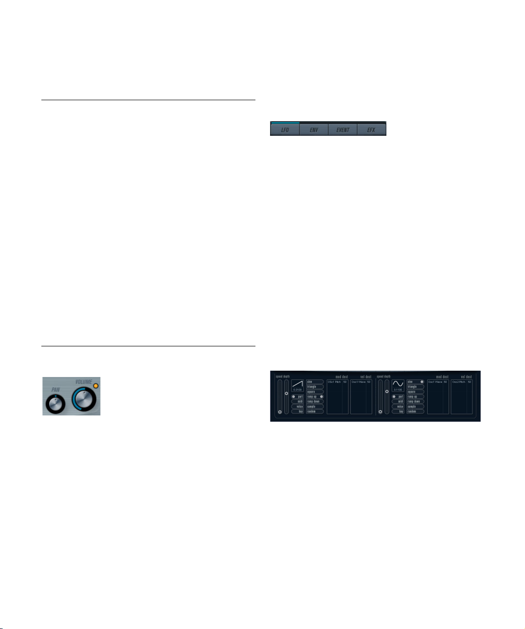
About the filter types
You select which filter type to use using the buttons around
the filter cutoff knob. The following filter types are available
(listed clockwise from 9 o’clock):
Type Description
12 db LP Low pass filters let low frequencies pass and cut out the
18 dB LP This low pass filter also has a cascade design, attenuat-
24 dB LP This filter type attenuates frequencies above the cutoff
24 dB LP II This low pass filter has a cascade design which attenuates
12 dB Band This band pass filter cuts both high and low frequencies
12 dB Notch This notch filter cuts off frequencies near the cutoff fre-
12 dB HP A high pass filter is the opposite of a low pass filter, cutting
24 dB HP This filter has a 24 dB/Octave slope, giving a bright and
high frequencies. This low pass filter has a gentler slope
dB/Octave above the cutoff frequency), leaving more
(12
of the harmonics in the filtered sound.
ing frequencies above the cutoff frequency with a 18 dB/
Octave slope, as used in the classic TB 303 synth.
frequency with a 24
warm and fat sound.
frequencies above the cutoff frequency with a 24
tave slope, which produces a warm and dark sound.
above and below the cutoff frequency with a 12
tave slope, producing a nasal and thin sound.
quency by 12 dB/Octave, letting the frequencies below
and above through. This produces a phaser-like sound.
out the lower frequencies and letting the high frequencies
pass. This high pass filter has a 12
a bright and thin sound.
sharp sound.
dB/Octave slope, which produces a
dB/Oc-
dB/Oc-
dB/Octave slope, giving
Master Volume and Pan
Modulation and controllers
The lower half of the control panel displays the various
modulation and controller assignment pages available as
well as the effect page. You switch between these pages
using the buttons below the Filter section.
The following pages are available:
• The LFO page has two low frequency oscillators (LFOs)
for modulating parameters – see below.
• The Envelope page contains the four Envelope generators which can be assigned to control parameters – see
“Envelope page” on page 36.
• The Event page contains the common MIDI controllers
(Mod wheel, Aftertouch, etc.) and their assignments – see
“Event page” on page 38.
• The Effect page has three separate effect types available; Distortion, Delay and Modulation – see “Effects
(EFX) page” on page 38.
LFO page
The LFO page is opened by clicking the LFO button at the
top of the lower half of the control panel. The page contains
all parameters and the modulation and velocity destinations
for two independent LFOs.
The master Volume controls the master volume (amplitude)
of the instrument. By default this parameter is controlled by
Envelope 1, to generate an amplitude envelope for the os
cillators.
The Pan knob controls the position in the stereo spectrum
for the instrument. You can use Pan as a modulation des
tination.
The included VST instruments
Depending on the currently selected preset, there may already be modulation destinations assigned, in which case
these are listed in the “Mod Dest” box for each LFO – see
“Assigning LFO modulation destinations” on page 35. A
low frequency oscillator (LFO) is used for modulating pa-
-
rameters, for example the pitch of an oscillator (to produce
vibrato), or for any parameter where cyclic modulation is
desired.
34
Page 35

The two LFOs have identical parameters:
Parameter Description
Speed This governs the rate of the LFO. I f MIDI Sync is activated
Depth This controls the amount of modulation applied by the
Waveform This sets the LFO waveform.
Sync mode
(Part/MIDI/
Voice/Key)
(see below), the available rate values are selectable as
note values, e.
in Cubase.
LFO. If set to zero, no modulation is applied.
This sets the sync mode for the LFO. See below for a
description.
g. beat increments of the sequencer tempo
About the sync modes
The Sync modes determine how the LFO cycle affects the
notes you play:
Parameter Description
Part In this mode, the LFO cycle is free running and affects all
MIDI In this mode the LFO rate is synced in various beat incre-
Voice In this mode each voice in the Part has its own indepen-
Key Same as Voice except that it is not free running – for
the voices in sync. “Free running” means that the LFO cy
cles continuously, and does not reset when a note is
played.
ments to MIDI clock.
dent LFO cycle (the LFO is polyphonic). These cycles are
also free running – each key down starts anywhere in the
LFO cycle phase.
each key down the LFO cycle starts over.
About the waveforms
Most standard LFO waveforms are available for LFO modulation. You use Sine and Triangle waveforms for smooth
modulation cycles, Square and Ramp up/down for different types of stepped modulation cycles and Random or
Sample for random modulation. The Sample waveform is
different. In this mode, one LFO actually samples and
holds the values of the other LFO at the chosen frequency.
Assigning LFO modulation destinations
To assign a modulation destination for an LFO, proceed
as follows:
1. Click in the “Mod Dest” box for one of the LFOs.
A pop-up menu appears in which all possible modulation destinations
are shown. All Sound parameters as well as most LFO and Envelope
parameters are available as destinations.
-
2. Select a destination, e. g. Filter Cut Off.
The selected modulation destination is now shown in the list. Beside the
destination, a default value (50) has been set. The value represents the
modulation amount.
• You can set positive and negative modulation values by
clicking on the value in the list, typing in a new value and
pressing the [Enter] key.
To enter negative values type a minus sign followed by the value.
3. Select a suitable LFO Waveform, Speed, Depth, and
Sync mode.
You should now hear the filter cutoff being modulated by the LFO.
4. Using the same basic method, you can add any number of modulation destinations for the LFO.
They are all listed in the “Mod Dest” box.
• To remove a modulation destination click on its name in
the list and select “Off” from the pop-up menu.
The included VST instruments
35
Page 36

Assigning LFO velocity destinations
You can also assign LFO modulation that is velocity controlled (i.e. governed by how hard or soft you strike a key).
Proceed as follows:
1. Click in the “Vel Dest” box for one of the LFOs.
A pop-up menu appears in which all possible velocity destinations are
shown.
2. Select a destination.
The selected velocity destination is now shown in the list. Beside the
destination, a default value (50) has been set. The value represents the
modulation amount. See below for an example of how velocity modula
tion works.
• You can set positive and negative values by clicking on
the value in the list, typing in a new value and pressing the
[Enter] key.
To enter negative values type a minus sign followed by the value.
3. Using the same basic method, you can add any number of velocity destinations for the LFO.
They are all listed in the “Vel Dest” box.
• To remove a modulation destination click on its name in
the list and select “Off” from the pop-up menu.
LFO modulation velocity control – an example:
If you follow the steps above and select the filter cutoff parameter as a Velocity destination, the following happens:
• The harder you strike the key, the more the filter cutoff
parameter is modulated by the LFO.
• If you enter a negative value for the velocity modulation
amount, the opposite happens; the harder you play the
less the filter cutoff is modulated by the LFO.
Envelope generators govern how a parameter value
changes when a key is pressed, when a key is held and
finally when a key is released.
On the Envelope page, the parameters for one of the four
envelope generators is shown at a time.
-
• You switch between the four envelopes in the section to
the left.
Clicking on either of the four mini curve displays 1 to 4 selects it and displays the corresponding envelope parameters to the right. The mini curve
displays also reflect the envelope settings for each corresponding enve
lope.
• Envelope generators have four parameters; Attack, Decay, Sustain, and Release (ADSR).
See below for a description of these.
• You can set envelope parameters in two ways; either by
using the sliders or by click-dragging the curve in the Envelope curve display.
You can also do this in the mini curve displays.
• By default Envelope 1 is assigned to the master volume,
and therefore acts as an amplitude envelope. The amplitude envelope is used to adjust how the volume of the
sound changes from the time you press a key until the key
is released.
If no amplitude envelope were assigned, there would be no output.
The Envelope parameters are as follows:
-
Envelope page
The Envelope page is opened by clicking the ENV button at
the top of the lower half of the control panel. The page contains all parameters and the modulation and velocity destinations for the four independent envelope generators.
The included VST instruments
Attack
The attack phase is the time it takes from zero to the maximum value. How long this takes is governed by the Attack
setting. If the Attack is set to “0”, the maximum value is
reached instantly. If this value is raised, it takes time before
the maximum value is reached. Range is from 0.0 millisec
onds to 91.1 seconds.
36
-
Page 37

Decay
After the maximum value has been reached, the value
starts to drop. How long this takes is governed by the Decay time parameter. The Decay time has no effect if the
Sustain parameter is set to maximum. Range is from 0.0
milliseconds to 91.1 seconds.
Sustain
The Sustain parameter determines the level the envelope
rests at after the Decay phase. Note that Sustain repre
sents a level, whereas the other envelope parameters represent times. Range is from 0 to 100.
Release
Release determines the time it takes for the value to fall
back to zero after releasing the key. Range is from 0.0 milliseconds to 91.1 seconds.
Punch
When Punch is activated, the start of the decay phase is
delayed by a few milliseconds (i.e. the envelope remains at
the top level for a moment before moving on to the decay
phase). The result is a punchier attack similar to a com
pressor effect. This effect is more pronounced with short
attack and decay times.
Retrigger
When Retrigger is activated, the envelope re-triggers each
time you play a new note. However, with certain textures/
pad sounds and a limited number of voices it is recommended to leave the button deactivated, due to click noises
that might occur, when the envelope is ended up abruptly.
This is caused by the incoming re-trigger that forces the en
velope to start over again.
Assigning Envelope modulation destinations
To assign a modulation destination for an Envelope, proceed as follows:
1. Click in the “Mod Dest” box for one of the Envelopes.
A pop-up menu appears in which all possible modulation destinations
are shown. All Sound parameters as well as most LFO and Envelope pa
rameters are available as destinations.
2. Select a destination, e. g. Filter Cut Off.
The selected modulation destination is now shown in the list. Beside the
destination, a default value (50) has been set. The value represents the
modulation amount.
• You can set positive and negative modulation values by
clicking on the value in the list, typing in a new value and
pressing the [Enter] key.
To enter negative values type a minus sign followed by the value.
3. Select a suitable envelope curve for the modulation.
You should now hear the filter cutoff being modulated by the envelope as
you play.
4. Using the same basic method, you can add any number of modulation destinations for the envelope.
They are all listed in the “Mod Dest” box.
• To remove a modulation destination click on its name in
the list and select “Off” from the pop-up menu.
Assigning Envelope velocity destinations
You can also assign Envelope modulation that is velocity
controlled (i.e. governed by how hard or soft you strike a
key). Proceed as follows:
1. Click in the “Vel Dest” box for one of the envelopes.
A pop-up menu appears in which all possible velocity destinations are
shown.
2. Select a destination.
The selected velocity destination is now shown in the list. Beside the destination, a default value (50) has been set. The value represents the modulation amount. See below for an example of how velocity modulation works.
• You can set positive and negative values by clicking on
the value in the list, typing in a new value and pressing the
[Enter] key.
To enter negative values type a minus sign followed by the value.
3. Using the same basic method, you can add any number of velocity destinations for the Envelope.
They are all listed in the “Vel Dest” box.
-
• To remove a modulation destination click on its name in
the list and select “Off” from the pop-up menu.
Envelope modulation velocity control – an example:
If you follow the steps above and select the filter cutoff parameter as a Velocity destination, the following happens:
• The harder you strike the key, the more the filter cutoff
parameter is modulated by the Envelope.
-
• If you enter a negative value for the velocity modulation
amount, the opposite happens; the harder you play the
less the filter cutoff is modulated by the Envelope.
The included VST instruments
37
Page 38

Event page
The Event page is opened by clicking the EVENT button
at the top of the lower half of the control panel. This page
contains the most common MIDI controllers and their respective assignments.
Effects (EFX) page
This page features three separate effect units: Distortion,
Delay and Modulation (Phaser/Flanger/Chorus). The Effect page is opened by clicking the EFX button at the top
of the lower half of the control panel.
The following controllers are available:
Controller Description
Modulation
Wheel
Velocity Velocity is used to control parameters according to how
Aftertouch Aftertouch, or channel pressure, is MIDI data sent when
Key Pitch
Tracking
The modulation wheel on your keyboard can be used to
modulate parameters.
hard or soft you play notes on your keyboard. A common
application of velocity is to make sounds brighter and
louder if you strike the key harder.
pressure is applied to a keyboard after the key has been
struck, and while it is being held down or sustained. Af
tertouch is often routed to control filter cutoff, volume,
and other parameters to add expression. Most (but not
all) MIDI keyboards send Aftertouch.
This can change parameter values linearly according to
where on the keyboard you play.
To assign any of these controllers to one or several parameters, proceed as follows:
1. Click in the “Mod Dest” box for one of the controllers.
A pop-up menu appears in which all possible modulation destinations
are shown. All Sound parameters as well as most LFO and Envelope pa
rameters are available as destinations.
2. Select a destination.
The selected modulation destination is now shown in the list. Beside the
destination, a default value (50) has been set. The value represents the
modulation amount when the controller is at its full range.
• You can set positive and negative modulation values by
clicking on the value in the list, typing in a new value and
pressing the [Enter] key.
To enter negative values type a minus sign followed by the value.
3. Using the same basic method, you can add any number of modulation destinations for the controllers.
They are all listed in the “Mod Dest” box for the respective controller.
• To remove a modulation destination click on its name in
the list and select “Off” from the pop-up menu.
• Each separate effect section is laid out with a row of
buttons that determine the effect type or characteristic
and a row of sliders for making parameter settings.
• To activate an effect, click the “Active” button so that a
dot appears.
Clicking again deactivates the effect.
Distortion
You can select between 4 basic distortion characteristics:
-
• Distortion provides hard clipping distortion.
• Soft Distortion provides soft clipping distortion.
• Tape Emulation produces distortion similar to magnetic tape
saturation.
• Tube Emulation produces distortion similar to valve amplifiers.
The parameters are as follows:
Parameter Description
Filter This parameter sets the crossover frequency of the dis-
-
Tone This parameter controls the relative amount of low pass
Drive Sets the amount of distortion by amplifying the input signal.
Level This controls the output level of the effect.
tortion filter. The distortion filter consists of a low pass filter and a high pass filter with a cutoff frequency equal to
the crossover frequency.
and high-pass filtered signal.
Delay
You can select between 3 basic delay characteristics:
• Stereo Delay has two separate delay lines panned left and right.
• In Mono Delay the two delay lines are connected in series for
monophonic dual tap delay effects.
• In Cross Delay the delayed sound bounces between the stereo
channels.
The included VST instruments
38
Page 39

The parameters are as follows:
Parameter Description
Song Sync This switches tempo sync of the delay times on or off.
Delay 1 Sets the delay time ranging from 0 ms to 728 ms. If MIDI
Delay 2 Same as Delay 1.
Feedback This controls the decay of the delays. With higher set-
Filter A low pass filter is built into the feedback loop of the de-
Level This controls the output level of the effect.
sync is activated the range is from 1/32 to 1/1; straight,
triplet or dotted.
tings the echoes repeat longer.
lay. This parameter controls the cutoff frequency of this
feedback filter. Low settings result in successive echoes
sounding darker.
Modulation
You can select between 3 basic modulation characteristics:
• The Phaser uses an 8-pole allpass filter to produce the classic
phasing effect.
• The Flanger is composed of two independent delay lines with
feedback for the left and the right channel respectively. The
delay time of both delays is modulated by one LFO with adjustable frequency.
• Chorus produces a rich chorus effect with 4 delays modulated
by four independent LFOs.
The parameters are as follows:
Parameter Description
Song Sync This switches tempo sync of the Rate parameter on or off.
Rate Sets the rate of the LFOs modulating the delay time. If
Depth This parameter controls the depth of the delay time mod-
Delay This parameter sets the delay time of the four delay lines.
Feedback The feedback parameter controls the amount of positive
Level This controls the output level of the effect.
Song Sync is activated the rate is synced to various beat
increments.
ulation.
or negative feedback for all four delay lines. The adjust
able range is from -1 to 1.
-
SR parameters
With these buttons you can change the sample rate. Lower
sample rates basically reduce the high frequency content
and sound quality, but the pitch is not altered. This is a great
way to emulate the “lo-fi” sounds of older digital synths!
• If button “F” is active, the selected Part’s program plays back
with the sample rate set in the host application.
• If button “1/2” is active, the selected Part’s program plays
back with half the original sample rate.
• If button “1/4” is active, the selected Part’s program plays
back with a quarter of the original sample rate.
• A bonus effect of using lower sample rates is that it re-
duces the load on the computer CPU, allowing more simultaneous voices to be played, etc.
The included VST instruments
39
Page 40

Index
Page 41

A
AmpSimulator 7
Apogee UV22HR 13
AutoPan 14
R
RingModulator 17
RoomWorks SE 21
Rotary 18
B
BitCrusher 7
C
Chopper 14
Chorus 15
Compressor 9
D
DaTube 8
Distortion 8
Dither 13
DualFilter 11
F
Filter plug-ins 11
Flanger 15
G
Groove Agent ONE 25
Grungelizer 8
L
Limiter 9
M
Metalizer 16
MonoDelay 6
MonoToStereo 22
S
StepFilter 12
StereoEnhancer 22
T
ToneBooster 13
Tranceformer 18
Tremolo 19
Tuner 23
V
Vibrato 19
VSTDynamics 10
W
WahWah 13
O
Octaver 20
P
Phaser 16
PingPongDelay 6
Pitch Correct 20
Prologue
About 30
Modulation parameters 34
Sound parameters 30
41
Index
 Loading...