

Page 1

Plug-in Reference
Page 2

Cristina Bachmann, Heiko Bischoff, Marion Bröer, Sabine Pfeifer, Heike Schilling
The information in this document is subject to change without notice and does not represent a commitment on the part
of Steinberg Media Technologies GmbH. The software described by this document is subject to a License Agreement
and may not be copied to other media except as specifically allowed in the License Agreement. No part of this publication may be copied, reproduced or otherwise transmitted or recorded, for any purpose, without prior written permission
by Steinberg Media Technologies GmbH.
All product and company names are ™ or ® trademarks of their respective owners. Windows XP is a trademark of
Microsoft Corporation. Windows Vista is a registered trademark or trademark of Microsoft Corporation in the United
States and/or other countries. The Mac logo is a trademark used under license. Macintosh and Power Macintosh are
registered trademarks. MP3SURROUND and the MP3SURROUND logo are registered trademarks of Thomson SA,
registered in the US and other countries, and are used under license from Thomson Licensing SAS.
Release Date: November 18, 2009
© Steinberg Media Technologies GmbH, 2009.
All rights reserved.
Page 3

Table of Contents
Page 4

5 The included effect plug-ins
6 Introduction
6 Delay plug-ins – PingPongDelay
7 Distortion plug-ins
7 Dynamics plug-ins
11 Modulation plug-ins
16 Other plug-ins
17 Restoration plug-ins – Grungelizer
18 Reverb plug-ins – RoomWorks SE
18 Spatial plug-ins – MonoToStereo
19 HALionOne
20 Introduction
20 HALionOne parameters
22 Index
4
Page 5

1
The included effect plug-ins
Page 6
Introduction
This chapter contains descriptions of the included plug-in
effects and their parameters.
In Cubase LE, the plug-in effects are arranged in a number of different categories. This chapter is arranged in the
same fashion, with the plug-ins listed in separate sections
for each effect category.
Delay plug-ins – PingPongDelay
Ö Most of the included effects are compatible with VST3,
this is indicated by an icon in front of the name of the plugin as displayed in plug-in selection menus (for further information, see the chapter “Audio Effects” in the Operation
Manual).
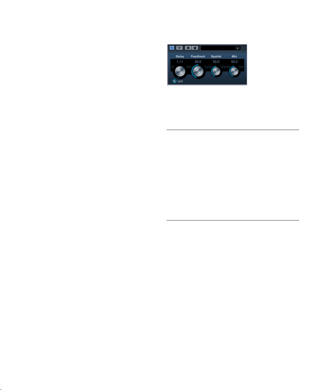
This is a stereo delay effect that alternates each delay repeat between the left and right channels. The effect can
either be tempo-based or use freely specified delay time
settings.
The parameters are as follows:
Parameter Description
Delay This is where you specify the base note value for the delay
Tempo sync
on/off
Feedback This sets the number of repeats for the delay.
Spatial This parameter sets the stereo width for the left/right
Mix Sets the level balance between the dry signal and the
if tempo sync is on (1/1–1/32, straight, triplet or dotted). If
tempo sync is off, it sets the delay time in milliseconds.
The button below the Delay knob is used to turn tempo
sync on or off. If set to off, the delay time can be set freely
with the Delay Time knob, without sync to tempo.
repeats. Turn clockwise for a more pronounced stereo
“ping-pong” effect.
effect. If PingPongDelay is used as a send effect, this
should be set to maximum as you can control the dry/
effect balance with the send.
6
The included effect plug-ins
Page 7
Distortion plug-ins
Dynamics plug-ins
This section contains descriptions of the plug-ins in the
“Distortion” category.
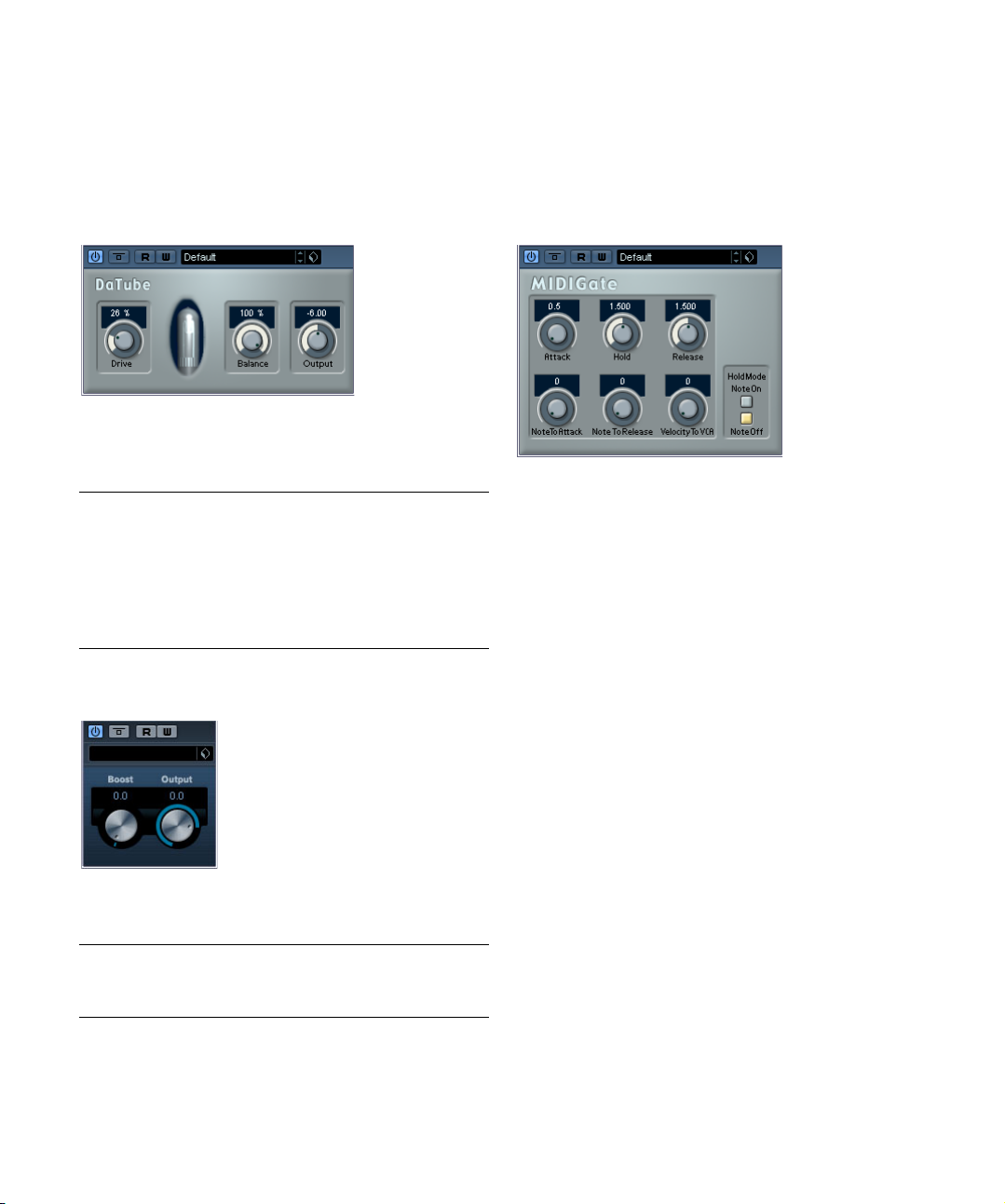
DaTube
This effect emulates the characteristic warm, lush sound
of a tube amplifier.
The parameters are as follows:
Parameter Description
Drive Regulates the pre-gain of the “amplifier”. Use high values
Balance This controls the balance between the signal processed
Output Adjusts the post-gain, or output level, of the “amplifier”.
if you want an overdriven sound just on the verge of
distortion.
by the Drive parameter and the dry input signal. For maximum drive effect, set this to its highest value.
Distortion
Distortion will add crunch to your tracks.
The parameters are as follows:
Parameter Description
Boost Increases the distortion amount.
Output Raises or lowers the signal going out of the effect.
This section contains descriptions of the plug-ins in the
“Dynamics” category.
MIDI Gate
Gating, in its fundamental form, silences audio signals below a certain set threshold level. That means, when a signal rises above the set level, the Gate opens to let the
signal through while signals below the set level are cut off.
MIDI Gate, however, is a Gate effect that is not triggered
by threshold levels, but instead by MIDI notes. Hence it
needs both audio and MIDI data to function.
Setting up
MIDI Gate requires both an audio signal and a MIDI input
to function.
To set it up, proceed as follows:
1. Select the audio to be affected by the MIDI Gate.
This can be audio material from any audio track, or even a live audio input
(provided you have a low latency audio card).
2. Select the MIDI Gate as an insert effect for the audio
track.
The MIDI Gate control panel opens.
3. Select a MIDI track to control the MIDI Gate.
This can be an empty MIDI track, or a MIDI track containing data, it
doesn’t matter. However, if you wish to play the MIDI Gate in real-time –
as opposed to having a recorded part playing it – the track has to be
selected for the effect to receive the MIDI output.
4. Open the Output Routing pop-up menu for the MIDI
track and select the MIDI Gate option.
The MIDI Output from the track is now routed to the MIDI Gate.
7
The included effect plug-ins
Page 8

What to do next depends on whether you are using live or
Limiter
Routing selector
Gate Compressor
recorded audio and whether you are using real-time or recorded MIDI. We will assume for the purposes of this
manual that you are using recorded audio, and play the
MIDI in real-time.
Make sure the MIDI track is selected and start playback.
5. Now play a few notes on your MIDI keyboard.
As you can hear, the audio track material is affected by what you play on
your MIDI keyboard.
The following MIDI Gate parameters are available:
Parameter Description
Attack This is used for determining how long it should take for
Hold Regulates how long the Gate remains open after a Note
Release This determines how long it takes for the Gate to close
Note To Attack The value you specify here determines to which extent
Note To
Release
Velocity To
VCA
Hold Mode Use this switch to set the Hold Mode. In Note-On mode,
the Gate to open after receiving a signal that triggers it.
On or Note Off message (see Hold Mode below).
(in addition to the value set with the Hold parameter).
the velocity values of the MIDI notes should affect the
Attack. The higher the value, the more the Attack time will
increase with high note velocities. Negative values will
give shorter Attack times with high velocities. If you do
not wish to use this parameter, set it to the 0 position.
The value you specify here determines to which extent the
velocity values of the MIDI notes should affect the Release.
The higher the value, the more the Release time will increase. If you do not wish to use this parameter, set it to
the 0 position.
This controls to which extent the velocity values of the
MIDI notes determine the output volume. A value of 127
means that the volume is controlled entirely by the velocity values, while a value of 0 means that velocities will
have no effect on the volume.
the Gate will only remain open for the time set with the
Hold and Release parameters, regardless of the length of
the MIDI note that triggered the Gate. In Note-Off mode
on the other hand, the Gate will remain open for as long
as the MIDI note plays, and then apply the Hold and Release parameters.
VSTDynamics
VSTDynamics is an advanced dynamics processor. It combines three separate processors: Gate, Compressor and
Limiter, covering a variety of dynamic processing functions.
The window is divided into three sections, containing controls and meters for each processor.
Activating the individual processors
You activate the individual processors using the buttons
at the bottom of the plug-in panel.
The Gate section
Gating, or noise gating, is a method of dynamic processing
that silences audio signals below a certain set threshold
level. As soon as the signal level exceeds the set threshold,
the gate opens to let the signal through. The Gate trigger
input can also be filtered using an internal side-chain.
The available parameters are as follows:
Parameter Description
Threshold
(-60–0dB)
state This indicates whether the gate is open (LED lights up in
Side-Chain
on/off
LP (Low pass),
BP (Band
pass), HP
(High pass)
Center
(50–22000Hz)
This setting determines the level where Gate is activated.
Signal levels above the set threshold trigger the gate to
open, and signal levels below the set threshold will close
the gate.
green), closed (LED lights up in red) or something in between (LED lights up in yellow).
This button activates the internal side-chain filter. This
lets you filter out parts of the signal that might otherwise
trigger the gate in places you don’t want it to, or to boost
frequencies you wish to accentuate, allowing for more
control over the gate function.
These buttons set the basic filter mode.
This sets the center frequency of the filter.
8
The included effect plug-ins
Page 9

Parameter Description
Q-Factor
(0.001–
10000)
Monitor
(On/Off)
Attack
(0.1–100ms)
Hold
(0–2000ms)
Release
(10–1000ms
or Auto mode)
This sets the resonance or width of the filter.
Allows you to monitor the filtered signal.
This parameter sets the time it takes for the gate to open
after being triggered.
This determines how long the gate stays open after the
signal drops below the threshold level.
This parameter sets the amount of time it takes for the
gate to close (after the set hold time). If the Auto button
is activated, Gate will find an optimal release setting, depending on the audio material.
The Compressor section
Compressor reduces the dynamic range of the audio,
making softer sounds louder or louder sounds softer, or
both. Compressor functions like a standard compressor
with separate controls for threshold, ratio, attack, release
and make-up gain parameters. Compressor features a
separate display that graphically illustrates the compressor curve shaped according to the Threshold, Ratio and
MakeUp Gain parameter settings. Compressor also features a Gain Reduction meter that shows the amount of
gain reduction in dB, and a program dependent Auto feature for the Release parameter.
The available parameters work as follows:
Parameter Description
Threshold
(-60–0dB)
Ratio
(1:1–8:1)
Make-Up
(0–24dB or
Auto mode)
Attack
(0.1–100ms)
Release
(10–1000ms
or Auto
mode)
Graphic
display
This setting determines the level where Compressor “kicks
in”. Signal levels above the set threshold are affected, but
signal levels below are not processed.
Ratio determines the amount of gain reduction applied to
signals over the set threshold. A ratio of 3:1 means that for
every 3dB the input level increases, the output level will increase by only 1dB.
This parameter is used to compensate for output gain loss,
caused by compression. When Auto is on, gain loss will be
compensated automatically.
This determines how fast Compressor will respond to signals above the set threshold. If the attack time is long,
more of the early part of the signal (attack) will pass
through unprocessed.
Sets the amount of time it takes for the gain to return to its
original level when the signal drops below the Threshold
level. If the Auto button is activated, Compressor will automatically find an optimal release setting that varies depending on the audio material.
Use the graphic display to graphically set the Threshold or
the Ratio value.
The Limiter section
Limiter is designed to ensure that the output level never
exceeds a certain set output level, to avoid clipping in following devices. Conventional limiters usually require very
accurate setting up of the attack and release parameters,
to prevent the output level from going beyond the set
threshold level. Limiter adjusts and optimizes these parameters automatically, according to the audio material.
You can also adjust the Release parameter manually.
The available parameters are the following:
Parameter Description
Output
(-24–+6dB)
Soft Clip
(On/Off)
Release
(10–1000ms
or Auto
mode)
This setting determines the maximum output level. Signal
levels above the set threshold are affected, but signal levels below are left unaffected.ì
Soft Clipper acts differently compared to the limiter. When
the signal level exceeds -6dB, SoftClip starts limiting (or
clipping) the signal “softly”, at the same time generating
harmonics which add a warm, tubelike characteristic to the
audio material.
This parameter sets the amount of time it takes for the gain
to return to its original level when the signal drops below
the threshold level. If the Auto button is activated, Limiter
will automatically find an optimal release setting that varies
depending on the audio material.
The Module Configuration button
In the bottom right corner of the plug-in panel you will find
a button with which you can set the signal flow order for
the three processors. Changing the order of the processors can produce different results, and the available options allow you to quickly compare what works best for a
given situation. Simply click the Module Configuration button to change to a different configuration. There are three
routing options:
• C-G-L (Compressor-Gate-Limit)
• G-C-L (Gate-Compressor-Limit)
• C-L-G (Compressor-Limit-Gate)
9
The included effect plug-ins
Page 10

Filter plug-ins
This section contains descriptions of the plug-ins in the
“Filter” category.
General operation
StepFilter can produce two simultaneous 16-step patterns
for the filter cutoff and resonance parameters, synchronized
to the sequencer tempo.
DualFilter
This effect filters out certain frequencies while allowing
others to pass through.
The following parameters are available:
Parameter Description
Position This parameter sets the filter cutoff frequency. If you set
Resonance Sets the sound characteristic of the filter. With higher
this to a negative value, DualFilter will act as a low-pass
filter. Positive values cause DualFilter to act as a highpass filter.
values, a ringing sound is heard.
StepFilter
Setting step values
• Setting step values is done by clicking in the pattern
grid windows.
• Individual step entries can be freely dragged up or down
the vertical axis, or directly set by clicking in an empty grid
box. By click-dragging left or right, consecutive step entries
will be set to the pointer position.
Setting filter cutoff values in the grid window.
• The horizontal axis shows the pattern steps 1–16 from
left to right, and the vertical axis determines the (relative)
filter cutoff frequency and resonance setting.
The higher up on the vertical axis a step value is entered, the higher the
relative filter cutoff frequency or filter resonance setting.
• By starting playback and editing the patterns for the cutoff and resonance parameters, you can hear how your filter
patterns affect the sound source connected to StepFilter
directly.
Selecting new patterns
• Created patterns are saved with the project, and up to 8
different cutoff and resonance patterns can be saved internally.
Both the cutoff and resonance patterns are saved together in the 8 Pattern
memories.
• To select new patterns you use the pattern selector.
New patterns are all set to the same step value by default.
StepFilter is a pattern-controlled multimode filter that can
create rhythmic, pulsating filter effects.
The included effect plug-ins
Pattern Selector
10
Page 11

Using pattern copy and paste to create variations
You can use the Copy and Paste buttons below the pattern
selector to copy a pattern to another pattern memory location, which is useful for creating variations on a pattern.
• Select the pattern you wish to copy, click the Copy button, select another pattern memory location and click Paste.
The pattern is copied to the new location, and can now be edited to create variations using the original pattern as a starting point.
StepFilter parameters
Parameter/
Value
Base Cutoff This sets the base filter cutoff frequency. Cutoff values
Base Resonance This sets the base filter resonance. Resonance values
Glide This will apply glide between the pattern step values,
Filter Mode This slider selects between low pass (LP), band pass
Sync 1/1 to 1/32
(Straight, Triplet
or Dotted)
Output Sets the overall volume.
Mix Adjusts the mix between dry and processed signal.
Description
set in the Cutoff grid window are values relative to the
Base Cutoff value.
set in the Resonance grid window are values relative to
the Base Resonance value. Note that very high Base
Resonance settings can produce loud ringing effects at
certain frequencies.
causing values to change more smoothly.
(BP) or high pass (HP) filter modes (from left to right
respectively).
This sets the pattern beat resolution, i.e. what note
values the pattern will play in relation to the tempo.
Modulation plug-ins
This section contains descriptions of the plug-ins in the
“Modulation” category.
AutoPan
This is a simple autopan effect. It can use different waveforms to modulate the left-right stereo position (pan), either
using tempo sync or manual modulation speed settings.
The parameters are as follows:
Parameter Description
Rate If tempo sync is on, this is where you specify the base
Tempo sync
on/off
Width Sets the depth of the AutoPan effect.
note value for tempo-syncing the effect (1/1 to 1/32,
straight, triplet or dotted).
If tempo sync is off, the auto-pan speed can be set freely
with the Rate knob, without sync to tempo.
The button below the Rate knob is used to switch tempo
sync on (the button lights up) or off.
11
The included effect plug-ins
Page 12

Chorus
Flanger
This is a single stage chorus effect. It works by doubling
whatever is sent into it with a slightly detuned version.
The parameters are as follows:
Parameter Description
Tempo sync
on/off
Rate If tempo sync is on, this is where you specify the base
Width This determines the depth of the chorus effect. Higher
Mix Sets the level balance between the dry signal and the ef-
The button below the Rate knob is used to switch tempo
sync on or off. The button is lit when tempo sync is on.
note value for tempo syncing the chorus sweep (1/1 to
1/32, straight, triplet or dotted).
If tempo sync is off, the sweep rate can be set freely with
the Rate knob, without sync to tempo.
settings produce a more pronounced effect.
fect. If Chorus is used as a send effect, this should be set
to maximum as you can control the dry/effect balance
with the send.
Flanger is a classic flanger effect with added stereo
enhancement.
The parameters are as follows:
Parameter Description
Tempo sync
on/off
Rate If tempo sync is on, this is where you specify the base
Feedback This determines the character of the flanger effect. Higher
Mix Sets the level balance between the dry signal and the ef-
The button below the Rate knob is used to switch tempo
sync on or off. The button is lit when tempo sync is on.
note value for tempo syncing the flanger sweep (1/1 to
1/32, straight, triplet or dotted).
If tempo sync is off, the sweep rate can be set freely with
the Rate knob, without sync to tempo.
settings produce a more “metallic” sounding sweep.
fect. If the Flanger is used as a send effect, this should be
set to maximum as you can control the dry/effect balance
with the send.
12
The included effect plug-ins
Page 13

Metalizer
The Metalizer feeds the audio signal through a variable
frequency filter, with tempo sync or time modulation and
feedback control.
Parameter Description
Feedback The higher the value, the more “metallic” the sound.
Sharpness Governs the character of the filter effect. The higher the
Tone Governs the feedback frequency. The effect of this will
On button Turns filter modulation on and off. When turned off, the
Mono button When this is on, the output of the Metalizer will be in mono.
Speed If tempo sync is on, this is where you specify the base
Tempo sync
on/off
Output Sets the overall volume.
Mix Sets the level balance between the dry signal and the ef-
value, the narrower the affected frequency area, producing sharper sound and a more pronounced effect.
be more noticeable with high Feedback settings.
Metalizer will work as a static filter.
note value for tempo-syncing the effect (1/1 to 1/32,
straight, triplet or dotted). Note that there is no note value
modifier for this effect.
If tempo sync is off, the modulation speed can be set
freely with the Speed knob, without sync to tempo.
The button above the Speed knob is used to switch tempo
sync on or off. The button is lit when tempo sync is on.
fect. If Metalizer is used as a send effect, this should be
set to maximum as you can control the dry/effect balance
with the send.
Phaser
Phaser produces the well-known “swooshing” phasing
effect with additional stereo enhancement.
The parameters are as follows:
Parameter Description
Tempo sync
on/off
Rate If tempo sync is on, this is where you specify the base
Feedback This determines the character of the phaser effect.
Mix Sets the level balance between the dry signal and the ef-
The button below the Rate knob is used to switch tempo
sync on or off. The button is lit when tempo sync is on.
note value for tempo syncing the phaser sweep (1/1 to
1/32, straight, triplet or dotted).
If tempo sync is off, the sweep rate can be set freely with
the Rate knob, without sync to tempo.
Higher settings produce a more pronounced effect.
fect. If the Phaser is used as a send effect, this should be
set to maximum as you can control the dry/effect balance
with the send.
13
The included effect plug-ins
Page 14

Ringmodulator
The Ringmodulator can produce complex, bell-like enharmonic sounds. Ring modulators work by multiplying two
audio signals. The ring modulated output contains added
frequencies generated by the sum of, and the difference
between, the frequencies of the two signals.
The Ringmodulator has a built-in oscillator that is multiplied with the input signal to produce the effect.
Parameter Description
Oscillator LFO
Amount
Oscillator Env.
Amount
Oscillator
Wave
Oscillator
Range
Oscillator
Frequency
Oscillator
Roll-Off
LFO Speed Sets the LFO Speed.
LFO Env.
Amount
Controls how much the oscillator frequency is affected
by the LFO.
Controls how much the oscillator frequency is affected
by the envelope (which is triggered by the input signal).
Positive and negative values can be set, with center position representing no modulation. Left of center, a loud input signal will decrease the oscillator pitch, whereas right
of center the oscillator pitch will increase when fed a loud
input.
Selects the oscillator waveform; square, sine, saw or
triangle.
Determines the frequency range of the oscillator in Hz.
Sets the oscillator frequency +/- 2 octaves within the selected range.
Cuts high frequencies in the oscillator waveform, to soften
the overall sound. This is best used when harmonically rich
waveforms are selected (e.g. square or saw).
Controls how much the input signal level – via the envelope generator – affects the LFO speed. Positive and negative values can be set, with center position representing
no modulation. Left of center, a loud input signal will slow
down the LFO, whereas right of center a loud input signal
will speed it up.
Parameter Description
LFO Waveform
Invert Stereo This inverts the LFO waveform for the right channel of the
Envelope
Generator
(Attack and
Decay dials)
Lock L<R When this button is enabled, the L and R input signals
Output Sets the overall volume.
Mix Adjusts the mix between dry and processed signal.
Selects the LFO waveform; square, sine, saw or triangle.
oscillator, which produces a wider stereo perspective for
the modulation.
The Envelope Generator section controls how the input
signal is converted to envelope data, which can then be
used to control oscillator pitch and LFO speed. It has two
main controls:
Attack sets how fast the envelope output level rises in response to a rising input signal.
Decay controls how fast the envelope output level falls in
response to a falling input signal.
are merged, and produce the same envelope output level
for both oscillator channels. When disabled, each channel has its own envelope, which affects the two channels
of the oscillator independently.
Rotary
The Rotary plug-in simulates the classic effect of a rotary
speaker. A rotary speaker cabinet features variable speed
rotating speakers to produce a swirling chorus effect, commonly used with organs. Rotary features all the parameters
associated with the real thing.
The parameters are as follows:
Parameter Description
Speed (Stop/
Slow/Fast)
Mix Adjusts the mix between dry and processed signals.
This controls the speed of the Rotary in three steps.
14
The included effect plug-ins
Page 15

Directing MIDI to the Rotary
For real-time MIDI control of the Speed parameter, MIDI
must be directed to the Rotary.
• Whenever the Rotary has been added as an insert effect (for an audio track or an FX channel), it will be available on the Output Routing pop-up menu for MIDI tracks.
If Rotary is selected on the “out:” menu, MIDI will be directed to the plugin from the selected track.
Tranceformer
Tranceformer is a ring modulator effect, in which the incoming audio is ring modulated by an internal, variable frequency oscillator, producing new harmonics. A second
oscillator can be used to modulate the frequency of the
first oscillator, in sync with the Song tempo if needed.
Parameter Description
Waveform
buttons
Tone Sets the frequency (pitch) of the modulating oscillator
Depth Governs the depth of the pitch modulation.
Speed If tempo sync is on, this is where you specify the base
Tempo sync
on/off
On button Turns modulation of the pitch parameter on or off.
Mono button Governs whether the output will be stereo or mono.
Sets the pitch modulation waveform.
(1 to 5000Hz).
note value for tempo-syncing the effect (1/1 to 1/32,
straight, triplet or dotted). Note that there is no note value
modifier for this effect. If tempo sync is off, the modulation speed can be set freely with the Speed knob, without
sync to tempo.
The button above the Speed knob is used to switch tempo
sync on or off. The button is lit when tempo sync is on.
Parameter Description
Output Adjusts the output level of the effect.
Mix Sets the level balance between the dry signal and the
effect.
Ö Clicking and dragging in the display allows you to adjust the Tone and Depth parameters at the same time!
Tremolo
Tremolo produces amplitude (volume) modulation.
Parameters are as follows:
Parameter Description
Rate If tempo sync is on, this is where you specify the base
Tempo sync
on/off
Depth This governs the depth of the amplitude modulation.
note value for tempo-syncing the effect (1/1 to 1/32,
straight, triplet or dotted).
If tempo sync is off, the modulation speed can be set
freely with the Rate knob, without sync to tempo.
The button below the Rate knob is used to switch tempo
sync on or off. The button is lit when tempo sync is on.
15
The included effect plug-ins
Page 16

Vibrato
The Vibrato plug-in produces pitch modulation.
Parameter Description
Rate If tempo sync is on, this is where you specify the base
Tempo sync
on/off
Depth This governs the depth of the pitch modulation.
note value for tempo-syncing the effect (1/1 to 1/32,
straight, triplet or dotted).
If tempo sync is off, the modulation speed can be set
freely with the Rate knob, without sync to tempo.
The button below the Rate knob is used to switch tempo
sync on or off. The button is lit when tempo sync is on.
Other plug-ins
This section contains descriptions of the plug-ins in the
“Others” category.
Bitcrusher
If you’re into lo-fi sound, Bitcrusher is the effect for you. It
offers the possibility of decimating and truncating the input audio signal by bit reduction, to get a noisy, distorted
sound. You can for example make a 24-bit audio signal
sound like an 8 or 4-bit signal, or even render it completely
garbled and unrecognizable. The parameters are:
Parameter Description
Mode Select one of four operating modes for the Bitcrusher.
Sample Divider This sets the amount by which the audio samples are
Depth Use this to set the desired bit resolution. A setting of 24
Output Governs the output level from the Bitcrusher. Drag the
Mix This slider regulates the balance between the output from
Each mode will produce a result sounding a bit different.
Modes I and III are nastier and noisier, while modes II and
IV are more subtle.
decimated. At the highest setting (65), nearly all of the information describing the original audio signal will be eliminated, turning the signal into unrecognizable noise.
gives the highest audio quality, while a setting of 1 will
create mostly noise.
slider upwards to increase the level.
the Bitcrusher and the original audio signal. Drag the slider
upwards for a more dominant effect, and drag it downwards if you want the original signal to be more prominent.
16
The included effect plug-ins
Page 17

Chopper
Chopper is a combined tremolo and autopan effect. It can
use different waveforms to modulate the level (tremolo) or
left-right stereo position (pan), either using tempo sync or
manual modulation speed settings. The parameters are as
follows:
Parameter Description
Waveform
buttons
Depth Sets the depth of the Chopper effect. This can also be
Speed If tempo sync is on, this is where you specify the base
Tempo sync
on/off
Stereo/Mono
button
Mix Sets the level balance between the dry signal and the ef-
Sets the modulation waveform.
set by clicking in the graphic display.
note value for tempo-syncing the effect (1/1 to 1/32,
straight, triplet or dotted). Note that there is no note value
modifier for this effect.
If tempo sync is off, the tremolo/auto-pan speed can be
set freely with the Speed knob, without sync to tempo.
The button above the Speed knob is used to switch
tempo sync on (the button lights up) or off.
Determines whether the Chopper will work as an autopanner (button set to “Stereo”) or a tremolo effect (button set to “Mono”).
fect. If Chopper is used as a send effect, this should be
set to maximum.
Restoration plug-ins – Grungelizer
The Grungelizer adds noise and static to your recordings
– kind of like listening to a radio with bad reception, or a
worn and scratched vinyl record. The available parameters
are as follows:
Parameter Description
Crackle This adds crackle to create that old vinyl record sound.
RPM switch When emulating the sound of a vinyl record, this switch
Noise This dial regulates the amount of static noise added.
Distort Use this dial to add distortion.
EQ Turn this dial to the right to cut off the low frequencies,
AC This emulates a constant, low hum of AC current.
Frequency
switch
Timeline This dial regulates the amount of overall effect. The far-
The farther to the right you turn the dial, the more crackle
is added.
lets you set the RPM (revolutions per minute) speed of
the record (33/45/78 RPM).
and create a more hollow, lo-fi sound.
This sets the frequency of the AC current (50 or 60Hz),
and thus the pitch of the AC hum.
ther to the right (1900) you turn this dial, the more noticeable the effect.
17
The included effect plug-ins
Page 18

Reverb plug-ins – RoomWorks SE
Spatial plug-ins – MonoToStereo
RoomWorks SE is a high-quality reverb plug-in. This plugin has the following parameters:
Parameter Description
Reverb Time Reverb Time in seconds.
Mix Determines the blend of dry (unprocessed) signal to wet
(processed) signal. When using RoomWorks SE inserted
in an FX channel, you will most likely want to set this to
100%.
This effect will turn a mono signal into a “pseudo-stereo”
signal. The plug-in must be inserted on a stereo track
playing a mono file to work.
The parameters are as follows:
Parameter Description
Width This controls the width or depth of the stereo enhance-
Color This parameter also generates differences between the
ment. Turn clockwise to increase the enhancement.
channels to increase the stereo effect.
18
The included effect plug-ins
Page 19

2
HALionOne
Page 20

Introduction
HALionOne is a sample player that can play sound content
in the *.hsb (HALion Sound Bank) format. These samples
have associated preset files that store the panel settings
and reference the HSB samples. Included are several presets (as *.vstpreset files).
The operation of HALionOne is very simple; load a preset (a *.vstpreset file for an Instrument Track) and start
playing! You do, however, have the option to tweak the
basic parameters to tailor the sound to your liking.
HALionOne parameters
The HALionOne panel parameters can vary according to
which parameters are stored in the HSB file. HSB files cannot be created with HALionOne, and HALionOne reads
only the HSB files supplied with Cubase LE. In these files,
certain parameters are assigned as part of the file and the
associated program (or preset). This means that for each
preset, only these assigned parameters are shown on the
instrument panel. Typically, these are filter cutoff, DCA and
DCF parameters and any assigned effect parameters (the
effects are “built in”).
If you load HALionOne for an Instrument track and select,
for example, the “Draw Organ” preset, the following parameters are shown:
Parameter Description
Cutoff This allows you to adjust filter frequency or cutoff. The fil-
Resonance Raising the filter resonance value will emphasize the fre-
DCF Amount Controls the amount of the DCF (filter) envelope.
DCA Attack Controls the time it takes for the DCA signal to reach its
DCA Decay Controls the time it takes the DCA signal to decay to the
ter used is a Waldorf Low Pass filter with a 24dB slope.
quencies around the set filter frequency.
highest level.
sustain level.
Parameter Description
DCA Sustain Controls the DCA signal level after the Decay phase, as
DCA Release Controls the DCA signal after a key is released.
DCA Amount Controls the amount of the DCA (amplifier) envelope.
long as you press the key on your MIDI keyboard.
These parameter assignments are used for many of the
HALionOne presets, but not for all. As stated above, other
parameters may be shown; these will be clearly labelled on
the panel. For most of the presets there are also associated
effects – the effect parameters are usually assigned to the
quick controls on the right and typically control the dry/wet
mix of the effect.
Effects Usage
• This button, located at the bottom right in the box displaying the preset name, allows you to bypass any effects.
The blue LED beside the button is lit if any effects are used in the preset.
Efficiency slider
The Efficiency slider provides a way of balancing audio
quality vs. conservation of computer power. The lower the
setting, the more voices are available. As a trade-off, sound
quality is reduced.
Voices allocated
• The Voices field dynamically displays the number of
voices currently used.
MIDI and Disk activity LEDs
The MIDI activity LED indicates received MIDI input. The
Disk LED will light up green when samples are streamed
from disk, and red when samples cannot be loaded from
disk in time. In such a case you should consider lowering
the Efficiency slider. When the disk LED doesn’t light up,
samples are read from memory.
Locate Contents
If you have moved the HALionOne content files to a different location (i.e. any other location than the folder in which it
was stored at installation time), you need to use the Locate
Contents function to inform HALion One about where to
find its files. This is done as follows:
• Right-click anywhere on the control panel and select
“Locate contents”.
A file dialog opens where you can navigate to the folder location.
20
HALionOne
Page 21

HALionOne and MIDI files
When the Preferences option “Import to Instrument Tracks”
is activated (on the MIDI–MIDI File page), importing a MIDI
file into Cubase LE will automatically set up instrument
tracks, with HALionOne as the associated instrument. This
allows you to quickly audition any imported MIDI files, to
change parameter settings or to add effects, etc.
21
HALionOne
Page 22

Index
Page 23

A
AutoPan 11
B
Bitcrusher 16
C
Chopper 17
Chorus 12
D
DaTube 7
Delay plug-ins 6
Distortion 7
Distortion plug-ins 7
Dynamics plug-ins 7
F
Flanger 12
H
HALionOne 19
M
Metalizer 13
MIDI Gate 7
Modulation plug-ins 11
MonoToStereo 18
T
Tranceformer 15
Tremolo 15
V
Vibrato 16
VST Instruments
HALionOne 19
VSTDynamics 8
O
Other plug-ins 16
P
Phaser 13
PingPongDelay 6
R
Restoration plug-ins 17
Reverb plug-ins 18
Ringmodulator 14
RoomWorks SE 18
Rotary 14
S
Spatial plug-ins 18
StepFilter 10
StereoEnhancer 18
23
Index
 Loading...