

Page 1
INSTRUCTION MANUAL
Model #: STC-Z3IRTL& STC-Z3IRTLNXT
Toll Free 1-877-269-8490 WWW.STEALTHCAM.COM
Version 4.0 1/13
Page 2

2
** IMPORTANT NOTE **
First, congratulations on purchasing one of the finest scouting cameras on the market today.
We appreciate your business and want to prove to you we are committed to providing you the
By giving our customers a new state of the art web interface, which provides you with video
tutorials and instruction on how to use the product in the most effective way.
TECHNICAL SUPPORT CUSTOMER SERVICE
EAIL: stealthcam@gsmorg.com CONTACT & HOURS
Please allow 48hrs for response. Toll Free: 1-877-269-8490
Stealth Cam, LLC Call Center Hours:
P.O. Box 539504 Mon - Fri / 8 AM – 6 PM (CST)
Grand Prairie, TX 75053-9504 www.stealthcam.com
Your Stealth Cam scouting camera is covered by a One Year Limited Warranty on parts and labor
from the date of original purchase, and purchases must be made through an authorized
dealer. The warranty covers defects in workmanship and materials. The warranty does not
apply to units, which have been damaged or abused intentionally or unintentionally. A purchase
from individuals or unauthorized Internet sites such as eBay voids the warranty.
Tampering with or altering the unit will void the warranty. Any unauthorized service will void
warranty. A copy of your original sales receipt must be produced for any warranty service and a
Return Authorization (RA) number must be obtained from customer service at 877-269-8490
prior to returning product.
To ensure optimum performance; your Stealth Cam (Wildview) camera may be eligible for periodical
Please check http://stealthcam.net/sc_downloads_d.html for the latest firmware downloads & sign up
for our weekly newsletter to stay informed on updates & new product news.
best product and support in the field.
Stealth Cam Limited Warranty
free software updates.
WWW.STEALTHCAM.COM
Toll Free 877-269-8490
Page 3

3
** IMPORTANT NOTE **
TRIAD equipped cameras include FREE Image Scan Software
download at: www.stealthcam.net/sc_image_scan.html
Stealth Cam Image Scan provides sophisticated motion searches
based on targeted zones within a selected series of time-lapse images.
Additional features include:
Watch days of video in minutes with variable speed playback
Import Time Lapse Photo sets from SD card to your computer
Open existing Time Lapse Photo sets on your computer
Process Photo Sets into high speed motion video
Quickly jog through the time lapse frames, forwards and backwards
Step frame forwards and backwards
Create videos that you can watch, email or upload
To ensure optimum performance; your Stealth Cam (Wildview) camera
may be eligible for periodical free software updates.
Please check http://stealthcam.net/sc_downloads_d.html for the latest
firmware downloads & sign up for our weekly newsletter to stay informed
on updates & new product news.
WWW.STEALTHCAM.COM
Toll Free 877-269-8490
Page 4

4
TABLE OF CONTENTS
Camera overview 5
Camera kit contents 8
General Information 9
Quick Start 10
Battery and Memory Installation 11
LCD display 14
Setup and Programming 16
Using the camera 24
Viewing & Deleting Files 26
Memory compatibility chart 28
Technical specs 29
Image capacity chart 32
Moon phase chart 34
Frequently Asked Questions (FAQs) 35
FCC Compliance 37
WWW.STEALTHCAM.COM
Toll Free 877-269-8490
Page 5
5
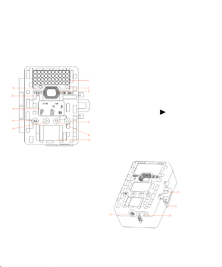
CAMERA OVERVIEW
12. External power jack
13. Tree screw mounting hole
14. Door latch
15. Locking hole
Front
1. IR LED window
2. LOW BATTERY warning RED LED
3. TEST mode sensing GREEN LED
4. Lens
5. LCD display
6. Menu button M
7. Confirm button
8. Downward button ▼
9. Upward button ▲
10. PIR sensing window
11. Microphone hole
WWW.STEALTHCAM.COM
Toll Free 877-269-8490
Page 6
6
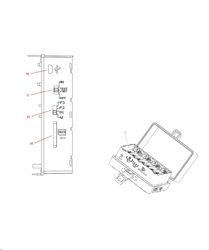
Inside
16. SD card slot
17. Function button
(ON, TEST/SET、OFF )
18. USB port
19. Battery compartment
20. Quick Set & Manual Program switch
WWW.STEALTHCAM.COM
Toll Free 877-269-8490
Page 7
7
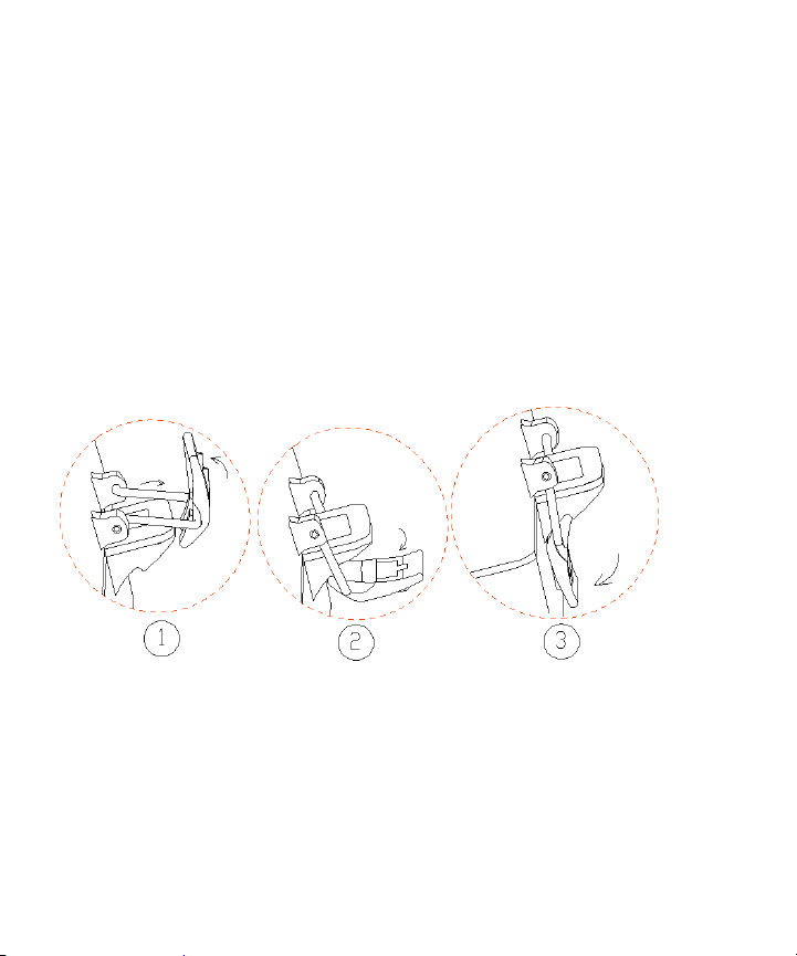
How to close the door latch.
WWW.STEALTHCAM.COM
Toll Free 877-269-8490
Page 8

8
CAMERA KIT CONTENT
Model STC-Z3IRTL or STC-Z3IRTLNXT Digital Scouting
Camera
User manual
Strap
WWW.STEALTHCAM.COM
Toll Free 877-269-8490
Page 9

9
GENERAL INFORMATION
Storing conditions
Operating Environment: 14 to 104 deg F (-10 to 40 deg C). 20-85%
relative humidity, non-condensing.
Special care instructions!!
The camera is designed to be weather resistant. Never attempt to
immerse the unit in water or any other liquid. This will damage the unit
and void the warranty.
Use a soft lens cloth for cleaning lens. Avoid touching lens with fingers.
Remove dirt or stains with a soft cloth dampened with water or neutral
detergent. Keep your camera in a dry and cool dust-free environment or
container when it is NOT used.
Take the batteries out, when camera is NOT to be used over an extended
period of time (2 weeks).
Avoid dropping your camera on to a hard surface.
Do not disassemble your camera.
Do not mix new and old batteries.
Do not open the camera for unauthorized service. This could cause
serious damage to the unit and WILL void the warranty.
NOTE: This camera is a precision electronic device. Do not attempt to
service this camera yourself, as opening or removing covers may expose
you to dangerous voltage points or other risks.
WWW.STEALTHCAM.COM
Toll Free 877-269-8490
Page 10

10
QUICK START GUIDE
This guide is designed to get you up and running in a matter of moments. To get the most
out of this advanced scouting tools, please read the manual thoroughly before operating
the camera. If you would like to modify any of the factory Default Settings, except for the
Time & Date, please see manual for instructions.
FACTORY DEFAULT SETTINGS:
Time Out:30 Seconds
Burst Mode: 1 Still Image (1.3Mp Resolution)
Video Mode:10 Seconds (VGA Resolution)
CAMERA SETUP:
1. Install 8 “AA” cell batteries in correct polarity (+/-) as indicated in battery
compartment.
2. Insert SD card into the camera.
SET DATE AND TIME:
1. To enter Date/Time setting, slide the power switch to TEST/SET position.
2. Press and Hold the M button for at least 3 seconds. Now the DATE and TIME icon will
blink.
3. Touch ▲ button to choose DATE setting.
4. Touch ▲ or ▼ button to increase or decrease your Month selection. Touch ▶button
to confirm and move to Date field.
5. Touch ▲ or ▼ button to increase or decrease your date selection. Touch ▶button to
confirm and move to Year field.
6. Touch ▲ or ▼ button to increase or decrease your year selection. Touch ▶button to
confirm your setting. The Date icon turns off and the Time icon is turns on.
7. Touch ▲ or ▼ button to increase or decrease the value for Hour. Touch ▶button to
confirm and move to Minute field.
8. Touch ▲ or ▼ button to increase or decrease the value for Minute. Touch ▶button to
confirm and move to Second field.
9. Touch ▲ or ▼ button to increase or decrease the value for Second. Touch ▶button to
and then touch the M button once. This will bring you back to the ready status.
WWW.STEALTHCAM.COM
Toll Free 877-269-8490
Page 11

11
BATTERY AND MEMORY INSTALLATION
WARNING: Do not use different Voltage lead acid battery other than
the one specified in this section. Doing so will damage the camera and
will void the warranty.
WARNING: ALWAYS have the camera in the OFF position when
installing or removing batteries and memory card. Removing batteries
or memory card while the camera is ON may damage the camera.
Your Stealth Cam Advanced Digital Scouting Camera is designed to operate
using two different types of battery power options.
Batteries “AA” cell
The internal battery compartment accepts 8 “AA” cell batteries. Be sure to
use high quality brand name alkaline batteries. Install batteries with correct
polarity (+/-) as noted inside the battery compartment.
12V Lead Acid external battery
The camera is equipped with an external power jack designed to accept a
barrel plug cable attached to a sealed lead acid battery. (Sold separately).
Battery cable and complete 12V Lead Acid battery kits are available wherever
Stealth Cam scouting cameras are sold or call Toll-free 877-269-8490. Only
Stealth Cam external battery accessories are recommended.
Make sure camera is in the OFF position.
Insert the external battery barrel plug into the DC 12V jack on the bottom
of camera housing.
Turn the camera power on.
WWW.STEALTHCAM.COM
Toll Free 877-269-8490
Page 12
12
NOTE: Please make sure the voltage and polarity (+/-) are correct
before connection. Incorrect voltage or polarity (+/-) will damage the
camera. When both internal and external batteries are connected, the
camera will draw power from the higher voltage source first.
Low Battery LED indicator
When the Red LED indicator stays on, this is an indication that the battery
power has been depleted and the camera will stop functioning soon. Replace
the battery as soon as possible.
NOTE: If the Red LED indicator is blinking, this is an indication of problem with
writing information to the SD card. It does not mean the battery is running
low. In this case you will need to perform a reset function. To reset the
camera, first you turn the camera off (front LCD screen may stay on). Take
one battery off and insert it back in immediately. Your program setting will
remain intact.
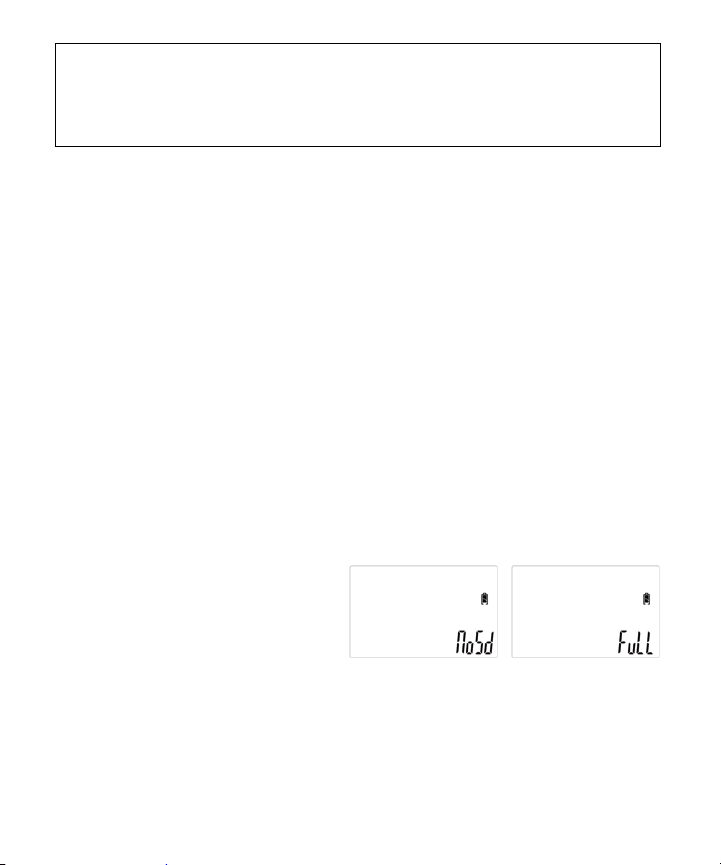
Memory Options
The camera is also equipped with an expandable media card slot capable of
accepting up to 16GB SD card with Class 6 or below speed rating (sold
separately). The front counter display will show the number of images stored
on the SD card. If no SD card is inserted the front counter display will show
“NoSd”.
When the memory is full, display
will show “FuLL” in the lower right
corner.
WWW.STEALTHCAM.COM
Toll Free 877-269-8490
Page 13

13
NOTE: Make sure camera is in the OFF position whenever adding or
removing memory.
WARNING:The above camera will not accept
Class 10 or above speed rating SD memory cards.
Inserting SD memory card
Insert SD memory card in to the SD card slot completely and in the
correct direction as shown by the sticker located at the side of the
housing.
To remove the SD memory card, depress the SD card and pull out the
card gently.
SD cards must be clean (no images from other sources). If you are using
the SD card from other cameras, please make sure to format the SD card
in your computer prior to use in your camera. New cards are good to use
straight from the package.
FORMAT – Definition: When you format a SD memory card, the operating
system erases all information and files on the card. Then it creates an internal
address tables that it later uses to locate information and files. Formatting
also removes all Hidden System files as well. Basically it cleans your SD
memory card just like if it was brand new. Please make sure to follow the
guidelines listed below:
SD Card size: 2Gb or below, format using File System type “FAT”.
WWW.STEALTHCAM.COM
Toll Free 877-269-8490
Page 14

14
SD Card size: 4GB or above, format using File System type “FAT32”.
Do not use File System type “NTFS” or “exFAT”, these formats are not
supported.
LCD DISPLAY
1. Locked icon (This represents that any programming is NOT allowed. All
setting buttons on front panel are disabled)
2. Unlocked icon (This represents camera power switch to SET mode,
allow customer to do programming by using setting buttons on front
panel)
3. PIR icon (This represents the camera’s triggering mode in PIR)
4. Time Lapse icon (This represents the camera is in Time Lapse mode)
5. Picture icon (This represents the camera is in still picture taking mode)
6. Video icon (This represents the camera is in video taking mode)
7. Burst mode icon (This represents the camera is in Burst mode setting –
# of pictures or length of AVI per PIR trigger)
WWW.STEALTHCAM.COM
Toll Free 877-269-8490
Page 15

15
8. Resolution icon (This represents the camera is in Resolution Mode
setting)
High Resolution – 3M Pixel / Low Resolution – 1.3M Pixel
9. Delete/Format icon (This represents the camera is in deleting
pictures/videos or format mode)
10. [Reserved for future use]
11. USB icon (This represents the camera is connected to the computer by
USB)
12. [Reserved for future use]
13. Battery icon (This represents the battery power level)
14. Time-Out icon (This represents the time out setting)
15. Number (small) icon (This represents the total number of captured
images. This also displays “set” when in the menus programming)
16. Number (BIG) icon (This represents the time and date)
17. Month/Date/Year icon
18. Hour/Minute/Second icon
19. T.Out icon (This represents the camera is in time out setting mode – to
be used with icon #16)
20. Time Lapse Start / Finish Programing Mode Indicator
21. [Reserved for future use]
22. Date icon(to use with icon #16 & 17)
23. Time icon (to use with icon #16 & 17)
WWW.STEALTHCAM.COM
Toll Free 877-269-8490
Page 16

16
Programming the Stealth Cam
This camera is equipped with 3 Quick set Program selection toggle switch
settings and a Manual program setting. Make sure camera is in the OFF
position BEFORE changing any toggle switches.
NOTE: If you choose one of the Preset settings, your camera will only
function in PIR mode not Time Lapse mode.
Quick Set 1 (P1) - This bypasses all user defined
settings and uses the following settings: (PIR
mode/ Resolution: 1.3MP / Burst: 3P / Time out:
30 seconds). Slide Power switch to TEST
position and you’ll see the screen on the right.
Quick Set 2 (P2)- This bypasses all user-defined
settings and uses the following settings: (PIR
mode/ Resolution: 1.3MP / Burst: 6P / Time out:
30 seconds). Slide Power switch to TEST position
and you’ll see the screen on the right.
Quick Set 3 (P3) - This bypasses all user-defined
settings and uses the following settings: (PIR
mode/ Video: VGA / Video clip: 10s / Time out:
30 seconds). Slide Power switch to TEST
position and you’ll see the screen on the right.
MANUAL (M) - This allows the user to define
what setting the camera will use. Slide Power
switch to TEST position and you’ll see the screen
on the right. After 2 seconds, this display will
return to Manual programing screen in the following section.
WWW.STEALTHCAM.COM
Toll Free 877-269-8490
Page 17

17
Programming the Stealth Cam using MANUAL mode
3Figure
Figure
设定触发方式,进入相机设置菜单后第一个功能选项就是设定相机的触发方式。分别为红外感应方式和定
时触发方式。设为感应触发方式在PIR 模式时有感应信号时可触发相机进行一轮拍摄,然后进行一轮间隔
延时后再次检测是否有感应信号。一直以此方式循环工作直到被结束拍摄。设为定时触发方式在PIR 模式
时,只有在当前时间段为有效时间段内时(关于此点在后文说明)。相机完成一轮间隔延时后就进行一轮
拍摄。在无效时间段时相机处于延时待机状态,不进行拍摄。如果用户设为定时触发方式相机自动强制将
拍摄模式设为拍摄照片。使用定时触发方式时不支持做活动影像拍摄。
感应触发 定时触发
设定拍摄模式。设置相机是拍摄相片还是拍摄活动影像。如果上一项设为定时触发时无此功能项。
拍摄照片 拍摄活动影像
Figure4
设定触发方式,进入相机设置菜单后第一个功能选项就是设定相机的触发方式。分别为红外感应方式和定
时触发方式。设为感应触发方式在PIR模式时有感应信号时可触发相机进行一轮拍摄,然后进行一轮间隔
延时后再次检测是否有感应信号。一直以此方式循环工作直到被结束拍摄。设为定时触发方式在PIR模式
时,只有在当前时间段为有效时间段内时(关于此点在后文说明)。相机完成一轮间隔延时后就进行一轮
拍摄。在无效时间段时相机处于延时待机状态,不进行拍摄。如果用户设为定时触发方式相机自动强制将
拍摄模式设为拍摄照片。使用定时触发方式时不支持做活动影像拍摄。
感应触发 定时触发
设定拍摄模式。设置相机是拍摄相片还是拍摄活动影像。如果上一项设为定时触发时无此功能项。
拍摄照片 拍摄活动影像
设定相片分辨率。高像素为3MG,低像素为 1.3MG.如果上一项设为拍摄活动影像模式时无此功能项。
高像素 低像素
Figure5
设置连拍照片张数 设置影像段落时间长度
Figure6
设置连拍照片张数 设置影像段落时间长度
设置间隔延时时间长度。每一轮与下一轮拍摄之间的间隔时间长度。方式为本轮拍摄完成。进行一个间隔
时长的延时,进行下一轮拍摄。可设置范围为1~59 秒或 1~59 分钟。分为两步设置,首先设定时长数据,
然后设定时长的计量单位(分或秒)。
设置延时时长数据
Slide the Quick Set switch to M position.
Programming is only allowed when camera’s power
switch is at the TEST/SET mode.
Slide the power switch from OFF to TEST/SET position;
you will hear two faint short beeps.
Touch M button to enter capture mode.
Step 1:Touch ▲ or ▼ button to choose either PIR
capture mode (Figure 1) or Time Lapse capture mode
(Figure 2). Touch ▶button to confirm your setting.
This will bring you to Still Picture or Video capture
mode. Picture icon will blink.
Step 2:Touch ▲ or ▼ button to choose either Still
Picture or Video capture mode (Figure 3).To choose
Still Picture mode, while the camera icon is blinking touch ▶button to
confirm. This will bring you to the Resolution mode.
Resolution icon will now blink.
Step 3:Touch ▲ or ▼ button to choose your
resolution (Figure 4) for 3M pixels. for1.3M
pixels. Touch ▶button to confirm your setting. Next
will bring you to burst mode setting (Figure 5).Burst
mode icon will now blink. Number icon will flash and
display the current number of pictures set.
Step 4:Touch ▲ or ▼ button to choose your burst
mode setting 1 to 9. Touch ▶button to confirm your
setting. Next setting will be the time out setting.
T.Out icon and Number (BIG) icon will blink (Figure 6).
WWW.STEALTHCAM.COM
Toll Free 877-269-8490
Page 18

18
模
式
活
动影像拍摄。
Figure8
Figure7
设置连拍照片张数 设置影像段落时间长度
设置间隔延时时间长度。每一轮与下一轮拍摄之间的间隔时间长度。方式为本轮拍摄完成。进行一个间隔
时长的延时,进行下一轮拍摄。可设置范围为1~59 秒或 1~59 分钟。分为两步设置,首先设定时长数据,
然后设定时长的计量单位(分或秒)。
设置延时时长数据
设置延时单位“分” 设置延时单位“秒”
Figure9
Figure10
Step 5:Touch ▲ or ▼ button to
choose your time out setting. Touch
▶button to confirm your setting. Now
the Time Out and Sec icon will blink.
Step 6:Touch ▲ or ▼ button to choose either Second or Minute(Figure
7).Touch ▶button to confirm your setting. All the icons on the screen will
blink then touch M button to exit programing mode.
For Video Mode:
Touch M button to enter capture mode. Repeat Step 1.
Then while you see the Picture icon blinking in Step 2:,
touch ▼ button to switch to Video mode. The Video
icon will be blinking (Figure 8). Touch ▶button to
confirm. This will bring you to the video recording
time mode. You will now see the Au icon blinking.
Touch ▲ or ▼ button to increase or decrease the
value range from 10 to 180 seconds (10,20,30,60,90,
120,150 or 180) - (Figure 9). Touch ▶button to confirm
and this will take you to the Time out setting and the
Time Out icon will blink.
Touch ▲ or ▼ button to choose your
time out setting. Touch ▶button to
confirm your setting.
Touch ▲ or ▼ button to choose either
Second or Minute(Figure 10).Touch ▶button to confirm your setting. All
the icons on the screen will blink, and then touch M button to exit
programing mode.
WWW.STEALTHCAM.COM
Toll Free 877-269-8490
Page 19

19
For Time Lapse Mode:
Figure12
设置开始时间“小时” 设置开始时间“分钟”
Figure13
Figure14
Figure11
模
式
设置开始时间“小时” 设置开始时间“分钟”
设置结束时间“小时” 设置结束时间“分钟”
Figure15
Figure16
Touch M button to enter capture mode.
Touch ▼ button to choose Time Lapse capture mode.
The Clock Icon will be blinking (Figure 11).
Touch ▶button to confirm. This will bring you to the
Resolution mode. Resolution icon will now blink
(Figure 12).
Repeat Step 3: through Step 6: to set your resolution,
burst mode, and your time out setting.
Once you complete Step 6:, your Time Lapse Start
Time will now blink (Figure 13).
Touch ▲ or ▼ button to choose your
start time “hour” (military time format).
Touch ▶button to confirm your setting
(Figure 13).
Touch ▲ or ▼ button to choose your
start time “minute”. Touch▶button to confirm your setting (Figure 14).
Finish time will now blink.
Touch ▲ or ▼ button to choose your
finish time ‘hour” (military time
format). Touch ▶button to confirm
your setting (Figure 15).
Touch ▲ or ▼ button to choose your finish time “minute”. Touch
▶button to confirm your setting (Figure 16).
Now you will see the entire screen icon display blink. Simply touch the M
button to exit the programing screen.
WWW.STEALTHCAM.COM
Toll Free 877-269-8490
Page 20

20
Ready for Use:
IMPORTANT: Please DO NOT slide the switch from OFF directly to
ON in one motion. Always slide to TEST/SET first, wait for the two
short beeps and then slide the switch to ON position.
Switch from TEST/SET position to the ON position. If you’re not ready to
use the camera, simply slide the power switch to the OFF position.
When ready to use, position your camera in the field. Slide the power
switch to TEST/SET. Wait for the 2 faint short beeps and then slide the
switch to the ON position.
WWW.STEALTHCAM.COM
Toll Free 877-269-8490
Page 21

21
To set Date and Time
Figure17
Figure18
Figure19
To enter Date/Time setting, slide the power
switch to TEST/SET position.
Press and Hold the M button for at least 3 seconds.
Now the DATE and TIME icon will blink (Figure 17).
Touch ▲ button to choose DATE setting (Figure
18).
Touch ▲ or ▼ button to increase or decrease
your Month selection. Touch ▶button to confirm
and move to Date field.
Touch ▲ or ▼ button to increase or decrease
your date selection. Touch ▶button to confirm
and move to Year field.
Touch ▲ or ▼ button to increase or decrease
your Year field.
Touch ▶button to confirm your setting. The Date
icon turns off and the Time icon is turns on
(Figure 19).
Touch ▲ or ▼ button to increase or decrease
the value for Hour. Touch ▶button to confirm
and move to Minute field.
Touch ▲ or ▼ button to increase or decrease
the value for Minute. Touch ▶button to confirm
and move to Second field.
Touch ▲ or ▼ button to increase or decrease
the value for Second. Touch ▶button to confirm
and then touch the M button once. This will
bring you back to the ready status.
WWW.STEALTHCAM.COM
Toll Free 877-269-8490
Page 22

22
Figure20
Figure21
Figure22
Figure23
Figure24
To Delete or Format memory card
To enter Delete/Format setting, slide the power
switch to TEST/SET position.
Press and Hold the M button for at least 3
seconds. Now the DATE and TIME icon will blink.
Touch ▶button once and the Delete/Format icon
will now blink (Figure 20).
Touch ▲ or ▼ button to choose YES or no (Figure
21). Touch ▶button to confirm. If you choose no
the screen will return to ready status. If you
choose YES, the screen will change to Figure 22
momentarily and then return to status screen.
To set 4 digits security code
To set 4 digits security code, slide the power switch to TEST/SET
position.
Press and Hold the M button for at least 3 seconds. Now the DATE
and TIME icon will blink.
Touch ▶button twice and the Lock icon will now
blink (Figure 23). LCD will now display SE-PASS
with the first digit blinking.
Touch ▲button and LCD will now display SE-PASS with the first digit
blinking (Figure 24).
Touch ▲ or ▼ button to select your 1st number.
Touch ▶button to confirm and move to the 2nd digit.
Touch ▲ or ▼ button to select your 2nd number.
Touch ▶button to confirm and move to the 3rd digit.
WWW.STEALTHCAM.COM
Toll Free 877-269-8490
Page 23

23
NOTE: After you set up your 4 digits security code, in order to
program or use the camera you must enter the 4 digits security code.
Figure25
Touch ▲ or ▼ button to select your 3rd number.
Touch ▶button to confirm and move to the 4th digit.
Touch ▲ or ▼ button to select your 4th number.
Touch ▶button to confirm the 4th digit.
When you are done, touch the M button to exit.
How to enter your 4 digits security code: Default code is “0000”
Slide the power switch to TEST/SET position.
LCD display will show En-PASS follow by 4 “0000” with the first digit
blinking (Figure 25).
Using the▲ or ▼ button to select your security code. After you
made your selection, you must touch▶button to move to the next
digit. Repeat until you have entered all 4 digits. After the 4th digit is
entered, you must touch ▶button to confirm the setting with all 4
digits flashing.
Touch M to begin your programing OR if you want to start using the
camera, then slide the power switch to the ON position.
WWW.STEALTHCAM.COM
Toll Free 877-269-8490
Page 24

24
USING THE CAMERA
Once all program settings have been setup properly, your Stealth Cam is ready
for field use.
Getting started
Listed below are some helpful pointers on how to use your camera to get the
best results.
Mount the camera about 4-5 feet high with the camera pointed at a slight
downward angle.
Mount the camera facing north or south, NOT east or west due to the
rising and setting of the sun could produce false triggers and overexposed
images.
If you’re covering a trail, face the camera down or up the trail. Most
commercial cameras take 1-3 seconds to sense motion/heat and take a
picture.
Clear out any brush or weeds in front of camera. This will cause false
pictures caused wind or high temperature days.
Double check battery before turning on the camera for use.
Make sure to insert the memory card after setting up the game camera.
Make sure to turn the camera ON (or take out of Test Mode) before you
leave.
Verify time and date is correct.
WWW.STEALTHCAM.COM
Toll Free 877-269-8490
Page 25

25
(Example: Mounting)
(Example: Trail Setup)
WWW.STEALTHCAM.COM
Toll Free 877-269-8490
Page 26

26
VIEWING AND DELETING FILES
Figure26
Viewing Images & Videos
Your Stealth Cam Digital Scouting Camera is a plug and play USB storage
device for users of Windows 2000 / ME / XP / Vista / Windows 7 operating
systems. This camera is not MAC compatible.
Viewing files on your computer via USB connection.
Make sure the camera’s power switch is in the OFF position first.
Plug the larger end of the USB cable into an available USB port on your
computer.
Plug the smaller end of USB cable into the camera’s side panel.
Slide the power switch to TEST/SET position. You will see the letter USB
showing on the bottom right hand corner of the LCD screen. (Figure 26)
Your computer will recognize the camera as a
Mass storage device, which you will find it
under MY COMPUTER.
WWW.STEALTHCAM.COM
Toll Free 877-269-8490
Page 27

27
At this point you have several options:
To view your images or play your videos: Click on the Removable
Storage device and then drill down to the file you want to see and
double click on the file name.
To save your images and videos: Highlight the file or files you want
to save and drag them to your hard drive.
To delete your images and videos: Highlight the files or files you
want to delete and press the [DELETE] button.
To erase all files and reformat you SD memory card: Right click on
the Removable Storage device under My Computer and select
FORMAT then click START. You will receive a Warning message press
[OK].Then CLOSE to exit.
NOTE: Make sure before you FORMAT you are certain it is the
Removable Storage device for the camera.
Once you’re done, power off the camera and unplug the cable from both
your computer and the camera. The camera will turn OFF automatically.
WWW.STEALTHCAM.COM
Toll Free 877-269-8490
Page 28

28
MEMORY COMPATIBILITY CHART
Kingmax
2G
Sandisk
2G, 4G, 8G
Toshiba
2G
PNY
2G, 4G, 8G, 16G
Kingston
2G, 4G, 8G, 16G
First Champion
1G, 2G, 4G, 8G, 16G
Digilux
1G, 2G
Lexar
4G, 8G, 16G
DANE-ELEC
4G, 8G, 16G
The following cards have been tested and approved for use with the STCZ3IRTL model at the time this manual was printer. For a more up-to-date
chart visit our website at www.stealthcam.net.
NOTE: Proper camera operation cannot be guaranteed when using
memory cards NOT listed above.
WWW.STEALTHCAM.COM
Toll Free 877-269-8490
Page 29

29
TECHNICAL SPECIFICATIONS
System Requirements and Compatibility
Windows Me/2000/XP/Vista/Windows 7 (Check our website for Mac
compatibility listings)
Pentium 4, 2GHz or above
1GB RAM (2GB recommended)
32 bits color, Resolution 1280 x 800 or above with built in 256MB
2GB free hard disc space
An available USB 1.1 port (USB 2.0 recommended)
Direct X 9.0 or above – Should come with your operating system already.
Optional: Windows compatible sound card and speaker.
Media player.
NOTE: If you have any questions regarding your PC specifications
please contact your PC manufacturer directly.
WWW.STEALTHCAM.COM
Toll Free 877-269-8490
Page 30

30
Camera Features and Specification
Camera lens: 5P high precision multi-layer glass lens with IR coating
Built in 2.0” B&W LCD display
External memory support: SD memory card up to 16GB. See
compatibility chart.
Resolution Options: 3.0Mp, 1.3Mp.
Image interpolated from 1.3M sensor.
Capturing Options: 1 to 9 image burst mode or VIDEO recording with
audio.
Video Recording length (in seconds): 10/20/30/60/90/120/150/180
Image performance for video stream: VGA
Video format: MJPEG
Image format: Standard JPEG
Auto white balance and auto expose.
Auto IR emitter light control
Effective Range for Still image (up to 50 ft.)
Effective Range for Video clip (up to 50 ft.)
Real time clock for date and time stamping
5 digits LCD Image counter
4 digit security code
Red Low battery LED indicator
Green Test LED indicator
Focusing: 5 ft. to infinity
WWW.STEALTHCAM.COM
Toll Free 877-269-8490
Page 31

31
Effective viewing Angle: 50 degrees
PIR detection angle 48 degrees
Power consumption:
Standby current: < 1.2mA.
Capture current < 75mA(Day Time),<400mA(Night Time with IR LED)
Interface type: USB 1.1
Power: 8 x AA size Batteries
External power: 12 volts battery pack(Sold separately)
WWW.STEALTHCAM.COM
Toll Free 877-269-8490
Page 32

32
IMAGE CAPACITY CHART
STC-Z3IRTL
Day
Memory Card Size
Resolution
Pixels
Data
size
Resolution
1G
2G
4G
8G
16G
HiGH
3.0M
615MB
2048x1536
1545
3089
6179
12358
24715
LOW
1.3M
246KB
1280x960
3862
7724
15447
30894
61789
AVI VGA 30's
VGA
17.7MB
640x480
54
107
215
429
859
Night
HIGH
3.0M
608KB
2048x1536
1563
3125
6250
12500
25000
LOW
1.3M
230KB
1280x960
4130
8261
16522
33043
66087
AVI VGA 30's
VGA
15.6MB
640x480
61
122
244
487
974
**Subject to card compatibility under different brands.
NOTE: Image Capacity Chart provides approximate number of images
or video clips based on resolution settings and the size of the memory
card. These Figures may vary depending on the amount of detail in the
image or video clip.
When the SD card is NOT FULL, but camera's front counter already reaches
9999, the camera will create a new folder to save the next data. Camera's
front counter will show 5 dashes “ - - - - - “. It will not reset the counter back
to 0000. On the other hand, when SD card is full, camera's counter will then
change the display the word "FULL". Images and Videos under each folder will
be named from 0001 up to 9999.
WWW.STEALTHCAM.COM
Toll Free 877-269-8490
Page 33

33
SD Card Capacity and Compatibility
Due to the rapidly changing memory card market please consult
www.stealthcam.com for the most up-to-date information regarding memory
cards.
May be protected by one or more U.S. Patent numbers:
6,735,387 / 6,768,868 / 6,834,162 / 7,149,422 / 7,308,196 / 7,593,632 /
7,710,457 / 7,873,266 / 8,254,776 / D653,276/ D673991/ 8,350,915
WWW.STEALTHCAM.COM
Toll Free 877-269-8490
Page 34

34
MOON PHASE SYMBOL CHART
WWW.STEALTHCAM.COM
Toll Free 877-269-8490
Page 35

35
FREQUENTLY ASKED QUESTIONS
Q: Is the infrared flash invisible?
A: The infrared flash will give off a low glow red light.
Q: Is my game camera Mac compatible?
A: Check our website to see if this model is compatible.
Q: Can I use rechargeable batteries in the camera?
A: Rechargeable batteries are fine for the camera; regular alkaline batteries
or Lithium battery designed for digital electronics are recommended for best
performance.
Q: When I use a memory card can I view the images on my personal digital
camera?
A: We do not recommend viewing memory card images taken in your game
camera or on any other digital camera. You may experience compatibility
issues.
Q: Will I lose my images and setting when the batteries die?
A: The camera has flash memory so your images and will remain intact but
you will need to reset your settings.
Q: What are my options if my camera is past it warranty?
A: We have an out of warranty program in which you may purchase a
reconditioned replacement unit for 50% or more off (based on retail price of
unit) discount exchange of your old unit.
WWW.STEALTHCAM.COM
Toll Free 877-269-8490
Page 36

36
Q: Can I use my game camera through a window or glass door?
A: Glass may disrupt your sensor beam we don’t advise using the camera in
this fashion.
Q: Do I need to recharge my 12V Battery Kit during the seasons it’s not in use?
A: The 12V Battery Kit should be recharge at least every 3 months, regardless
if it is being used or not, in order to preserve the working condition of the
battery inside the unit.
NOTE: For the latest updates and information please check our website
regularly.
WWW.STEALTHCAM.COM
Toll Free 877-269-8490
Page 37

37
WARNING: Modification not approved by the party responsible for
compliance could void user’s authority to operate.
FCC Compliance
This equipment has been tested and found to comply with the limits for Class B digital
device, pursuant to part 15 of the FCC Rules. These limits are designed to provide
reasonable protection against harmful interference in a residential installation. This
equipment generates uses and can radiate radio frequency energy and, if not installed
and used in accordance with the instructions, may cause harmful interference to radio
or television receptions, which can be determined by turning the equipment off and
on, the user is encouraged to try to correct the interference by one or more of the
following measure:
Reorient or relocate the receiving antenna.
Increase the separation between the equipment and the receiver.
Connect the equipment into an outlet on a circuit different from that to which
the receiver is connected.
Consult the dealer or an experienced radio/TV technician for help.
This device complies with part 15 of the FCC Rules. Operation is subject to the
following two conditions: (1) This device may not cause harmful interference, and (2)
this device must accept any interference received, including interference that may
cause undesired operation.
WWW.STEALTHCAM.COM
Toll Free 877-269-8490
Page 38

38
Product specifications are subject to change. Stealth Cam is not responsible for any photographic or
typographical errors.
WWW.STEALTHCAM.COM
Toll Free 877-269-8490
 Loading...