


Instruction Manual
RESIDENTIAL GAS WATER HEATERS
NOT FOR USE IN MANUFACTURED (MOBILE) HOMES
• For Your Safety •
ANODORANTISADDEDTOTHEGASUSED
BYTHISWATERHEATER.
ALLTECHNICALAND WARRANTY QUESTIONS: SHOULD BE DIRECTED TO THE LOCAL DEALER FROM WHOM THE WATER HEATER WAS PURCHASED.IFYOUAREUNSUCCESSFUL,PLEASEWRITETOTHECOMPANYLISTEDONTHERATINGPLATEONTHEWATERHEATER.
KEEPTHIS MANUALIN THE POCKET ON HEATER FOR FUTURE REFERENCE
WHENEVER MAINTENANCE ADJUSTMENT OR SERVICE IS REQUIRED.
PRINTED IN THE U.S.A 1204 |
1 |
PART NO. 196293-002 |

SAFE INSTALLATION, USE AND SERVICE
Your safety and the safety of others is extremely important in the installation, use and servicing of this water heater.
Many safety-related messages and instructions have been provided in this manual and on your own water heater to warn you and others of a potential injury hazard. Read and obey all safety messages and instructions throughout this manual. It is very important that the meaning of each safety message is understood by you and others who install, use or service this water heater.
This is the safety alert symbol. It is used to alert you to potential personal injury hazards. Obey all safety messages that follow this symbol to avoid possible injury or death.
|
|
|
|
DANGER indicates an imminently |
|
|
DANGER |
|
|
|
|
|
||
|
|
|
hazardous situation which, if not avoided, |
|
|
|
|
|
could result in death or injury. |
|
|
|
|
|
|
|
|
|
|
|
|
|
|
|
|
|
|
|
WARNING indicates a potentially hazardous |
|
|
WARNING |
|
|
|
|
|
||
|
|
|
situation which, if not avoided, could result |
|
|
|
|
|
in death or injury. |
|
|
|
|
|
|
|
|
|
|
|
|
|
|
CAUTION indicates a potentially hazardous |
|
|
CAUTION |
|
|
|
|
|
||
|
|
|
situation which, if not avoided, may result |
|
|
|
|
|
in minor or moderate injury. |
|
|
|
|
|
|
|
|
|
|
|
|
|
|
CAUTION used without the safety alert |
|
|
|
|
|
|
CAUTION |
|
symbol indicates a potentially hazardous |
|
|
|
situation which, if not avoided, could result |
||
|
|
|
|
in property damage. |
|
|
|
|
|
|
|
|
|
|
All safety messages will generally tell you about the type of hazard, what can happen if you do not follow the safety message and how to avoid the risk of injury.
IMPORTANT DEFINITIONS
•Qualified Installer: A qualified installer must have ability equivalent to a licensed tradesman in the fields of plumbing, air supply, venting and gas supply, including a thorough understanding of the requirements of the National Fuel Gas Code as it relates to the installation of gas fired water heaters. The qualified installer must have a thorough understanding of this instruction manual.
•Service Agency: A service agency also must have ability equivalent to a licensed tradesman in the fields of plumbing, air supply, venting and gas supply, including a thorough understanding of the requirements of the National Fuel Gas Code as it relates to the installation of gas fired water heaters. The service agency must also have a thorough understanding of this instruction manual, and be able to perform repairs strictly in accordance with the service guidelines provided by the manufacturer.
•Gas Supplier: The Natural Gas or Propane Utility or service which supplies gas for utilization by the gas burning appliances within this application. The gas supplier typically has responsibility for the inspection and code approval of gas piping up to and including the Natural Gas meter or Propane storage tank of a building. Many gas suppliers also offer service and inspection of appliances within the building.
2
GENERAL SAFETY
3

TABLE OF CONTENTS
SAFE INSTALLATION, USEAND SERVICE .............................. |
2 |
GENERAL SAFETY .................................................................. |
3 |
TABLE OF CONTENTS .............................................................. |
4 |
INTRODUCTION ........................................................................ |
4 |
Preparing for the New Installation ................................... |
4 |
TYPICAL INSTALLATION ....................................................... |
5,6 |
LOCATING THE NEW WATER HEATER ................................. |
7-9 |
Facts to Consider About Location ................................ |
7,8 |
Insulation Blankets ........................................................... |
8 |
Combustion Air and Ventilation for Appliances |
|
Located in Unconfined Spaces ....................................... |
8 |
Combustion Air and Ventilation for Appliances |
|
Located in Confined Spaces ......................................... |
8,9 |
INSTALLING THE NEW WATER HEATER .......................... |
10-14 |
Water Piping .............................................................. |
10,11 |
Temperature-Pressure Relief Valve ............................... |
11 |
Filling the Water Heater .................................................. |
12 |
Venting ...................................................................... |
12,13 |
Gas Piping ................................................................. |
13,14 |
Sediment Traps .............................................................. |
14 |
LIGHTING &OPERATING INSTRUCTIONS .......................... |
15,16 |
TEMPERATUREREGULATION ................................................ |
17 |
FORYOUR INFORMATION ................................................ |
17,18 |
Start Up Conditions ................................................... |
17,18 |
Draft Hood Operation .................................................. |
17 |
Condensation ......................................................... |
17,18 |
Smoke/Odor ................................................................ |
18 |
Thermal Expansion ...................................................... |
18 |
Strange Sounds .......................................................... |
18 |
Operational Conditions ................................................... |
18 |
Smelly Water ............................................................... |
18 |
“Air” in Hot Water Faucets ......................................... |
18 |
High Temperature Shut Off System ............................ |
18 |
PERIODICMAINTENANCE ................................................. |
19-21 |
Venting System Inspection ............................................ |
19 |
Burner Inspection ........................................................... |
19 |
Burner Cleaning .............................................................. |
19 |
Housekeeping ........................................................... |
19,20 |
Anode Rod Inspection .................................................... |
20 |
Temperature-Pressure Relief Valve Operation .............. |
20 |
Draining .......................................................................... |
20 |
Drain Valve Washer Replacement ................................. |
20 |
Service ........................................................................... |
21 |
LEAKAGE CHECKPOINTS ...................................................... |
21 |
REPAIR PARTS ....................................................................... |
22 |
TROUBLESHOOTINGGUIDELINES ......................................... |
23 |
WARRANTY ..................................................................... |
Insert |
INTRODUCTION
Thank You for purchasing this water heater. Properly installed and maintained, it should give you years of trouble free service.
Abbreviations Found In This Instruction Manual:
•UL - Underwriters Laboratories Inc.
•ANSI -American National Standards Institute
•NFPANational Fire ProtectionAssociation
•ASME - American Society of Mechanical Engineers
•GAMA - Gas Appliance Manufacturer’s Association
•CAN - Canada
•EPACT - Energy Policy Act
•CSA - Canadian Standards Association
This gas-fired water heater is design certified by Underwriters Laboratories Inc. under American National Standard/CSA Standard for Gas Water Heaters ANSI Z21.10.3 • CSA 4.3 (current edition).
PREPARING FOR THE INSTALLATION
1.Read the “General Safety” section, page 3 of this manual first and then the entire manual carefully. If you don’t follow the safety rules, the water heater will not operate properly. It could cause DEATH, SERIOUSBODILYINJURYAND/ORPROPERTYDAMAGE.
This manual contains instructions for the installation, operation, and maintenance of the gas-fired water heater. It also contains warnings throughout the manual that you must read and be aware of. All warnings and all instructions are essential to the proper operation of the water heater and your safety. Since we cannot put everything on the first few pages, READ THE ENTIRE MANUAL BEFORE
ATTEMPTING TO INSTALLOR OPERATETHE WATERHEATER.
2.The installation must conform with these instructions and the local code authority having jurisdiction. In the absence of local codes, installations shall comply with the National Fuel Gas Code ANSI Z223.1/NFPA 54. This publication is available from the CSA International, 8501 East Pleasant Valley Rd., Cleveland Ohio 44131, or The National Fire Protection Association, 1 Batterymarch Park, Quincy, MA02269.
3.If after reading this manual you have any questions or do not understand any portion of the instructions, call the local gas utility or the manufacturer whose name appears on the rating plate.
4.Carefully plan the place where you are going to put the water heater. Correct combustion, vent action, and vent pipe installation are very important in preventing death from possible carbon monoxide poisoning and fires, see Figures 3 and 8.
Examine the location to ensure the water heater complies with the “Locating the New Water Heater” section in this manual.
5.For California installation this water heater must be braced, anchored, or strapped to avoid falling or moving during an earthquake. See instructions for correct installation procedures. Instructions may be obtained from California Office of the State Architect, 400 P Street, Sacramento, CA 95814.
6.Massachusetts Code requires this water heater to be installed in accordance with Massachusetts 248-CMR 2.00: State Plumbing Code and 248-CMR 5.00.
7.Complies with SCAQMD rule #1146.2 and districts having equivalent NOx requirements.
4

TYPICAL INSTALLATION
GET TO KNOW YOUR WATER HEATER - GAS MODELS
A |
Vent Pipe |
I |
Ground Joint Union |
Q |
Temperature-Pressure Relief Valve |
B |
Drafthood |
J |
Drip Leg (Sediment Trap) |
R |
Rating Plate |
C |
Anode |
K |
Inner Door |
S |
Flue Baffle(s) |
D |
Hot Water Outlet |
L |
Outer door |
T |
Thermostat |
E |
Outlet |
M |
Union |
U |
Drain Valve |
F |
Insulation |
N |
Inlet Water Shut-off Valve |
V |
Pilot and Main Burner |
G |
Gas Supply |
O |
Cold Water Inlet |
W |
Flue |
H |
Manual Gas Shut-off Valve |
P |
Inlet Dip Tube |
X |
Drain Pan |
* INSTALL IN ACCORDANCE WITH |
(T) THERMOSTAT |
|
|
LOCAL CODES. |
|
* DRIP LEG AS REQUIRED BY |
|
LOCAL CODES. |
|
* ALL PIPING MATERIALS TO BE |
|
SUPPLIED BY CUSTOMERS. |
|
|
|
|
|
(V) PILOT & MAIN BURNER - NATURAL GAS
(V) PILOT & MAIN BURNER - PROPANE GAS
THERMOCOUPLE |
MAIN |
PILOT |
BURNER |
|
|
BURNER |
|
**CLOSED WATER SYSTEMS ARE THOSE
WITH BACK FLOW PREVENTION DEVICES
INSTALLED IN THE WATER SERVICE LINE.
FIGURE1.
5

TYPICAL INSTALLATION
MIXING VALVE USAGE
FIGURE2.
This appliance has been design certified as complying with ANSI Z21.10.3 latest edition for water heaters and is considered suitable for:
Water (Potable) Heating and Space Heating: All models are considered suitable for water (potable) heating and space heating.
HOTTERWATERCANSCALD:
Water heaters are intended to produce hot water. Water heated to a temperature which will satisfy space heating, clothes washing, dish washing, and other sanitizing needs can scald and permanently injure you upon contact. Some people are more likely to be permanently injured by hot water than others. These include the elderly, children, the infirm, or physically/mentally handicapped. If anyone using hot water in your home fits into one of these groups or if there is a local code requiring a certain temperature water at the hot water tap, then you must take special precautions. In addition to using the lowest possible temperature setting that satisfies your hot water needs, a means such as a *Mixing Valve, shall be used at the hot water taps used by these people or at the water heater. Mixing valves are available at plumbing supply or hardware stores. Consult a qualified installer or service agency. Follow mixing valve manufacturer’s instructions for installation of the valves. Before changing the factory setting on the thermostat, read the “Temperature Regulation” section in this manual, see Figures 15 and 16.
6
LOCATING THE NEW WATER HEATER
FACTS TO CONSIDER ABOUT THE LOCATION
Carefully choose an indoor location for the new water heater, because the placement is a very important consideration for the safety of the occupants in the building and for the most economical use of the appliance. This water heater is not for use in manufactured
(mobile) homes or outdoor installation.
Whether replacing an old water heater or putting the water heater in a new location, the following critical points must be observed:
1.Select a location indoors as close as practical to the gas vent or chimney to which the water heater vent is going to be connected, and as centralized with the water piping system as possible.
2.Selected location must provide adequate clearances for servicing and proper operation of the water heater.
Installation of the water heater must be accomplished in such a manner that if the tank or any connections should leak, the flow will not cause damage to the structure. For this reason, it is not advisable to install the water heater in an attic or upper floor. When such locations cannot be avoided, a suitable drain pan should be installed under the water heater. Drain pans are available at your local hardware store. Such a drain pan must have a minimum length and width of at least 2” (51 mm) greater than the water heater dimensions and must be piped to an adequate drain. The pan must not restrict combustion air flow.
Water heater life depends upon water quality, water pressure and the environment in which the water heater is installed. Water heaters are sometimes installed in locations where leakage may result in property damage, even with the use of a drain pan piped to a drain. However, unanticipated damage can be reduced or prevented by a leak detector or water shut-off device used in conjunction with a piped drain pan. These devices are available from some plumbing supply wholesalers and retailers, and detect and react to leakage in various ways:
•Sensors mounted in the drain pan that trigger an alarm or turn off the incoming water to the water heater when leakage is detected.
•Sensors mounted in the drain pan that turn off the water supply to the entire home when water is detected in the drain pan.
•Water supply shut-off devices that activate based on the water pressure differential between the cold water and hot water pipes connected to the water heater.
•Devices that will turn off the gas supply to a gas water heater while at the same time shutting off its water supply.
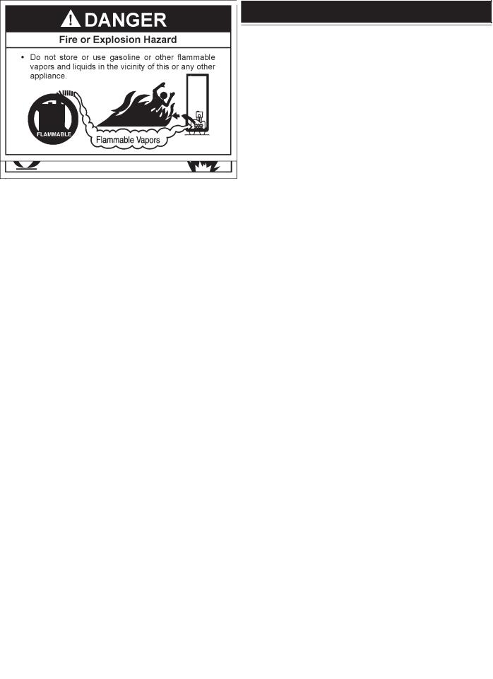
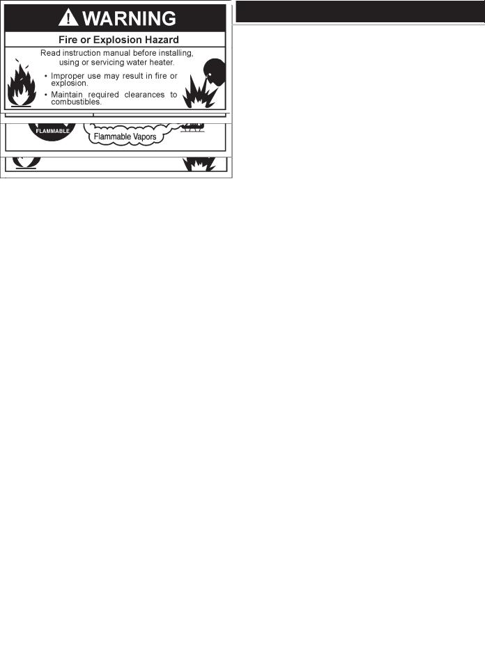
INSTALLATIONS IN AREAS WHERE FLAMMABLE LIQUIDS (VAPORS)ARE LIKELY TO BE PRESENT OR STORED (GARAGES, STORAGE AND UTILITY AREAS, ETC.): Flammable liquids (such as gasoline, solvents, propane [LP or butane, etc.] and other substances such as adhesives, etc.) emit flammable vapors which can be ignited by a gas water heater’s pilot light or main burner. The resulting flashback and fire can cause death or serious burns to anyone in the area, as well as property damage. If installation in such areas is your only option, then the installation must be accomplished in a way that the pilot flame and main burner flame are elevated from the floor at least 18 inches. While this may reduce the chances of flammable vapors, from a floor spill being ignited, gasoline and other flammable substances should never be stored or used in the same room or area containing a gas water heater or other open flame or spark producing appliance. NOTE: Flammable vapors may be drawn by air currents from other
areas of the structure to the appliance.
Also, the water heater must be located and/or protected so it is not subject to physical damage by a moving vehicle.
This water heater must not be installed directly on carpeting. Carpeting must be protected by metal or wood panel beneath the appliance extending beyond the full width and depth of the appliance by at least 3” (76.2 mm) in any direction, or if the appliance is installed in an alcove or closet, the entire floor must be covered by the panel. Failure to heed
this warning may result in a fire hazard.
7
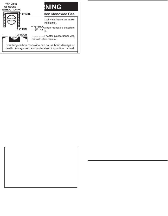
Minimum clearances between the water heater and combustible construction are 0 inch at the sides and rear, 4” (102 mm) at the front, and 6” (153 mm) from the vent pipe. Clearance from the top of the jacket is 12” (305 mm) on most models. Note that a lesser dimension may be allowed on some models, refer to the label attached adjacent to the gas control valve on the water heater, see Figure 3.
FIGURE
FIGURE3.
A gas water heater cannot operate properly without the correct amount of air for combustion. Do not install in a confined area such as a closet, unless you provide air as shown in the “Locating The New Water Heater” section. Never obstruct the flow of ventilation air. If you have any doubts or questions at all, call your gas supplier. Failure to provide the proper amount of combustion air can result in a fire or explosion and cause death, serious bodily injury, or property damage.
FIGURE4.
If this water heater will be used in beauty shops, barber shops, cleaning establishments, or self-service laundries with dry cleaning equipment, it is imperative that the water heater or water heaters be installed so that combustion and ventilation air be taken from outside these areas.
Propellants of aerosol sprays and volatile compounds, (cleaners, chlorine based chemicals, refrigerants, etc.) in addition to being highly flammable in many cases, will also change to corrosive hydrochloric acid when exposed to the combustion products of the water heater. The results can be hazardous, and also cause product failure.
INSULATION BLANKETS
Insulation blankets are available to the general public for external use on gas water heaters but are not necessary with these products. The purpose of an insulation blanket is to reduce the standby heat loss encountered with storage tank heaters. Your water heater meets or exceeds the EPACT standards with respect to insulation and standby loss requirements, making an insulation blanket unnecessary.
Should you choose to apply an insulation blanket to this heater, you should follow these instructions (For identification of components mentioned below, see Figure 1). Failure to follow these instructions can restrict the air flow required for proper combustion, potentially resulting in fire, asphyxiation, serious personal injury or death.
•Do not apply insulation to the top of the water heater, as this will interfere with safe operation of the draft hood.
•Do not cover the outer door, thermostat or temperature & pressure relief valve.
•Do not allow insulation to come within 2" (50.8 mm) of the floor to prevent blockage of combustion air flow to the burner.
•Do not cover the instruction manual. Keep it on the side of the water heater or nearby for future reference.
•Do obtain new warning and instruction labels from the manufacturer for placement on the blanket directly over the existing labels.
•Do inspect the insulation blanket frequently to make certain it does not sag, thereby obstructing combustion air flow.
COMBUSTION AIR AND VENTILATION FOR APPLIANCES LOCATED IN UNCONFINED SPACES
UNCONFINED SPACE is space whose volume is not less than 50 cubic feet per 1,000 Btu per hour (4.8 m3 per kW) of the aggregate input rating of all appliances installed in that space. Rooms communicating directly with the space in which the appliances are installed, through openings not furnished with doors, are considered a part of the unconfined space.
In unconfined spaces in buildings, infiltration may be adequate to provide air for combustion, ventilation and dilution of flue gases. However, in buildings of tight construction (for example, weather stripping, heavily insulated, caulked, vapor barrier, etc.), additional air may need to be provided using the methods described in “CombustionAir and Ventilation for Appliances Located in Confined Spaces.”
COMBUSTION AIR AND VENTILATION FOR APPLIANCES LOCATED IN CONFINED SPACES
CONFINED SPACE is a space whose volume is less than 50 cubic feet per 1,000 Btu per hour (4.8 m3 per kW) of the aggregate input rating of all appliances installed in that space.
8
 Loading...