


Instruction Manual for Residential
Gas Water Heaters
NOT FOR USE IN MANUFACTURED (MOBILE) HOMES
GAMA certification applies to all residential gas water heaters with capacities of 20 to 100 gallons with input rating of 75,000 BTU/Hr. or less.
AND WARRANTY QUESTIONS: SHOULD BE DIRECTED TO THE LOCAL DEALER FROM HEATER WAS PURCHASED. IF YOU ARE UNSUCCESSFUL, PLEASE WRITE TO THE
ON THE RATING PLATE ON THE WATER HEATER.
|
AN ODORANT IS ADDED TO THE GAS |
|||||||
|
Your Safety USED BY THIS WATER HEATER |
|||||||
|
|
|
|
|
|
|
|
|
|
|
|
|
|
|
WARNING |
|
|
|
|
|
||||||
|
the information in these |
|
|
|
|
|
|
|
|
|
|
Improper installation, adjustment, alteration, |
|||||
|
not followed exactly, a fire |
|
|
service or maintenance can cause DEATH, |
||||
|
result, causing property |
|
|
SERIOUS BODILY INJURY, OR PROPERTY |
||||
|
injury or death. |
|
|
DAMAGE. Refer to this manual for assistance |
||||
|
|
|
|
or consult the local gas utility for further |
||||
|
or use gasoline or other |
|||||||
|
|
information. |
||||||
|
and liquids in the vicinity |
|
|
|
|
|
|
|
|
|
|
|
|
|
|
||
|
other appliance. |
|
|
|
|
|
|
|
|
IF YOU SMELL GAS |
|
|
|
WARNING |
|
|
|
|
|
|
|
|
||||
|
light any appliance. |
|
|
|
|
drawn by air cur- |
||
|
|
Flammable vapors may be |
||||||
|
any electrical switch; do not |
|
rents from other areas of the structure to this |
|||||
|
in your building. |
|
appliance. |
|||||
|
call your gas supplier from a |
|
|
|
|
|
|
|
|
phone. Follow the gas suppli- |
|
|
|
|
|
|
|
. |
|
|
|
|
|
|
|
|
|
reach your gas supplier, call |
|
|
|
WARNING |
|
|
|
. |
|
|
|
|
|
|||
|
|
READ THE GENERAL SAFETY SECTION |
||||||
|
service must be performed |
|
BEGINNING ON INSIDE COVER AND THEN |
|||||
|
installer, service agency or |
|
THIS ENTIRE MANUAL BEFORE INSTALLING |
|||||
. |
|
|
OR OPERATING THIS WATER HEATER. |
|||||
|
|
|
|
|
|
|
|
|
|
|
|
|
|
|
|
|
|
|
for Future Reference. |
184115-000 |
||||||
|
|
|
03-03 |
|||||

General Safety
 WARNING
Improper installation, adjustment, alteration, service or maintenance can cause DEATH, SERIOUS BODILY INJURY, OR PROPERTY DAMAGE. Refer to this manual or consult your local gas utility for assistance.
 WARNING
At the time of manufacture this water heater was provided with a combination temperature-pressure relief valve certified by a nationally-recognized testing laboratory that maintains periodic inspection of production of listed equipment or materials, as meeting the requirements for Relief Valves and Automatic Gas Shutoff Devices for Hot Water Supply Systems, and the current edition of ANSI Z21.22 and the code requirements of ASME. If replaced, the valve must meet the requirements of local codes, but not less than a combination temperature and pressure relief valve certified as meeting the requirements for Relief Valves and Automatic Gas Shutoff Devices for Hot Water Supply Systems, ANSI Z21.22 by a nationally recognized testing laboratory that maintains periodic inspection of production of listed equipment or materials.
The valve must be marked with a maximum set pressure not to exceed the marked hydrostatic working pressure of the water heater (150 lbs. p.s.i.) and a discharge capacity not less than the water heater input rate as shown on the model rating plate. (Electric heaters - watts divided by 1000 x 3412 equal BTU/Hr. rate.)
Your local jurisdictional authority, while mandating the use of a temperature-pressure relief valve complying with ANSI Z21.22 and ASME, may require a valve model different from the one furnished with the water heater.
Compliance with such local requirements must be satisfied by the installer or end user of the water heater with a locally prescribed temperature-pressure relief valve installed in the designated opening in the water heater in place of the factory furnished valve.
For safe operation of the water heater, the relief valve must not be removed from it’s designated opening or plugged.
The temperature-pressure relief valve must be installed directly into the fitting of the water heater designated for the relief valve. Position the valve downward and provide tubing so that any discharge will exit only within 6 inches above, or at any distance below the structural floor. Be certain that no contact is made with any live electrical part. The discharge opening must not be blocked or reduced in size under any circumstances. Excessive length, over 30 feet, or use of more than four elbows can cause restriction and reduce the discharge capacity of the valve.
No valve or other obstruction is to be placed between the relief valve and the tank. Do not connect tubing directly to discharge drain unless a 6″ air gap is provided. To prevent bodily injury, hazard to life, or property damage, the relief valve must be allowed to discharge water in quantities should circumstances demand. If the discharge pipe is not connected to a drain or other suitable means, the water flow may cause property damage.
The Discharge Pipe:
—Must not be smaller in size than the outlet pipe size of the valve, or have any reducing couplings or other restrictions.
—Must not be plugged or blocked.
—Must be of material listed for hot water distribution.
—Must be installed so as to allow complete drainage of both the temperature-pressure relief valve, and the discharge pipe.
—Must terminate at an adequate drain.
—Must not have any valve between the relief valve and tank.
 WARNING
WATER HEATERS EQUIPPED FOR ONE TYPE GAS ONLY: This water heater is equipped for one type gas only. Check the rating plate near the gas control valve for the correct gas. DO NOT USE THIS WATER HEATER WITH ANY GAS OTHER THAN THE ONE SHOWN ON THE MODEL RATING PLATE. Failure to use the correct gas can cause problems which can result in DEATH, SERIOUS BODILY INJURY, OR PROPERTY DAMAGE. If you have any questions or doubts consult your gas supplier or local utility.
 WARNING
A fire can start if combustible materials such as clothing, cleaning materials, or flammable liquids are placed against or next to the water heater.
 WARNING
INSTALLATIONS IN AREAS WHERE FLAMMABLE LIQUIDS (VAPORS) ARE LIKELY TO BE PRESENT OR STORED (GARAGES, STORAGE, AND UTILITY AREAS, ETC): Flammable liquids (such as gasoline, solvents, propane (LP) or butane, etc.), all of which emit flammable vapors, may be improperly stored or used in such areas. The gas water heater pilot light or main burner can ignite such vapors. The resulting flashback and fire can cause death or serious burns to anyone in the area, as well as property damage.
If installation in such areas is your only option, then the installation must be accomplished in a way that the pilot flame and main burner flame are elevated from the floor at least 18 inches. While this may reduce the chances of flammable vapors from a floor spill being ignited, gasoline and other flammable substances should never be stored or used in the same room or area containing a gas water heater or other open flame or spark producing appliance.
NOTE: Flammable vapors may be drawn by air currents from other areas of the structure to the appliance.
 WARNING
HOTTER WATER CAN SCALD: Water heaters are intended to produce hot water. Water heated to a temperature which will satisfy space heating, clothes washing, dish washing, and other sanitizing needs can scald and permanently injure you upon contact. Some people are more likely to be permanently injured by hot water than others. These include the elderly, children, the infirm, or physically/mentally handicapped. If anyone using hot water in your home fits into one of these groups or if there is a local code or state law requiring a certain temperature water at the hot water tap, then you must take special precautions. In addition to using the lowest possible temperature setting that satisfies your hot water needs, a means such as a mixing valve, shall be used at the hot water taps used by these people or at the water heater. Mixing valves are available at plumbing supply or hardware stores. Follow manufacturers instructions for installation of the valves. Before changing the factory setting on the thermostat, read the “Temperature Regulation” section in this manual.
 WARNING
BEFORE LIGHTING PROPANE (L.P.) GAS WATER HEATERS: Propane (L.P.) gas is heavier than air. Should there be a leak in the system, the gas will settle near the ground. Basements, crawl spaces, skirted areas under manufactured (mobile) homes (even when ventilated), closets and areas below ground level will serve as pockets for the accumulation of this gas. Before attempting to light or relight the water heater’s pilot or turning on a nearby electrical light switch, be absolutely sure there is no accumulated gas in the area. Search for odor of gas by sniffing at ground level in the vicinity of the appliance. If odor is detected, follow steps indicated at “For Your Safety” on the cover page of this manual then leave the premises.
2

General Safety
 WARNING
This water heater must not be installed directly on carpeting. Carpeting must be protected by a metal or wood panel beneath the appliance extending beyond the full width and depth of the appliance by at least 3 inches (76.2mm) in any direction, or if the appliance is installed in an alcove or closet, the entire floor must be covered by the panel. Failure to heed this warning may result in a fire hazard.
 WARNING
A gas water heater cannot operate properly without the correct amount of air for combustion. Do not install in a confined area such a closet, unless you provide air as shown in the “Locating The New Water Heater” section. Never obstruct the flow of ventilation air. If you have any doubts or questions at all, call your gas company. Failure to provide the proper amount of combustion air can result in a fire or explosion and can cause DEATH, SERIOUS BODILY INJURY, OR PROPERTY DAMAGE.
 WARNING
If this water heater will be used in beauty shops, barber shops, cleaning establishments, or self-service laundries with dry cleaning equipment, it is imperative that the water heater or water heaters be installed so that combustion and ventilation air be taken from outside these areas. Refer to the “Locating The New Water Heater” section of this manual and also the current edition of the National Fuel Gas Code, ANSI Z223.1, also referred to as NFPA 54 for specifics provided concerning air required.
 WARNING
VENT DAMPERS - Any vent damper, whether it is operated thermally or otherwise must be removed if its use inhibits proper drafting of the water heater.
Thermally Operated Vent Dampers: Gas-fired water heaters having thermal efficiency in excess of 80% may produce a relatively low flue gas temperature. Such temperatures may not be high enough to properly open thermally operated vent dampers. This would cause spillage of flue gases and may cause carbon monoxide poisoning.
Vent dampers must bear evidence of certification as complying with the current edition of American National Standard ANSI Z21.68 (ANSI Z21.66 & 67, respectively, cover electrically and mechanically actuated vent dampers). Before installation of any vent damper, consult the gas utility for further information.
 WARNING
1.The appliance and its individual shutoff valve must be disconnected from the gas supply piping system during any pressure testing of the gas system at test pressures in excess of 1⁄2 pound per square inch (3.5kPa).
2.The appliance must be isolated from the gas supply piping system by closing its individual manual shutoff valve during any pressure testing of the gas supply piping system at test pressures equal or less than 1⁄2 pound per square inch (3.5kPa).
 WARNING
Soot build-up indicates a problem that requires correction before further use. Turn “OFF” gas to water heater and leave “OFF” until repairs are made, because failure to correct the cause of the sooting can result in a fire or explosion causing DEATH, SERIOUS BODILY INJURY, OR PROPERTY DAMAGE.
 WARNING
The water heater with draft hood installed must be properly vented to a chimney which terminates outdoors. Never operate the water heater unless it is vented to the outdoors and has adequate air supply to avoid risks of improper operation, explosion or asphyxiation.
 WARNING
Obstructed or deteriorated vent systems may present a serious health risk or asphyxiation.
 WARNING
Chemical vapor corrosion of the flue and vent system may occur if air for combustion contains certain chemical vapors. Spray can propellants, cleaning solvents, refrigerator and air conditioner refrigerants, swimming pool chemicals, calcium and sodium chloride, waxes, bleach, and process chemicals are typical compounds which are potentially corrosive.
 WARNING
Minimum clearances between the water heater and combustible construction are 1″ at the sides and rear, 4″ at the front, and 6″ from the vent pipe. Clearance from the top of the jacket is 18″ on most models. Note that a lesser dimension may be allowed on some models, refer to the label attached adjacent to the gas control valve on the water heater.
 WARNING
HYDROGEN GAS: Hydrogen gas can be produced in a hot water system that has not been used for a long period of time (generally two weeks or more). Hydrogen gas is extremely flammable and explosive. To prevent the possibility of injury under these conditions, we recommend the hot water faucet be opened for several minutes at the kitchen sink before any electrical appliances which are connected to the hot water system are used (such as a dishwasher or washing machine). If hydrogen gas is present, there will probably be an unusual sound similar to air escaping through the pipe as the hot water faucet is opened. There must be no smoking or open flame near the faucet at the time it is open.
 WARNING
INSULATING JACKETS: When installing an external water heater insulation jacket on a gas water heater:
a.DO NOT cover the temperature-pressure relief valve.
b.DO NOT put insulation over any part of the top of the gas water heater.
c.DO NOT put insulation over the gas control valve or gas control valve/burner cover, or any access areas to the burner.
d.DO NOT let insulation around the gas water heater to get within 8 inches of the floor (air must get to the burner).
e.DO NOT cover or remove operating instructions, and safety related warning labels and materials affixed to the water heater.
Failure to heed this will result in the possibility of a fire or explosion.
 WARNING
Flood damage to a water heater may not be readily visible or immediately detectible. However, over a period of time a flooded water heater will create dangerous conditions which can cause DEATH, SERIOUS BODILY INJURY, OR PROPERTY DAMAGE. Call a qualified service technician or contractor to replace a flooded water heater. Do not attempt to repair the unit! It must be replaced!
 CAUTION
WATER HEATERS EVENTUALLY LEAK: Installation of the water heater must be accomplished in such a manner that if the tank or any connections should leak, the flow of water will not cause damage to the structure. For this reason, it is not advisable to install the water heater in an attic or upper floor. When such locations cannot be avoided, a suitable drain pan should be installed under the water heater. Drain pans are available at your local hardware store. Such a drain pan must be not greater than 11⁄2 inches deep, have a minimum length and width of at least 2 inches greater than the water heater dimensions and must be piped to an adequate drain. The pan must not restrict combustion air flow.
3

Table of Contents
General Safety................................................................................................................................ |
2,3 |
Table of Contents ......................................................................................................................... |
4 |
Introduction ......................................................................................................................................... |
5 |
Preparing for the New Installation.................................................................. |
5 |
Typical Installation..................................................................................................................... |
6 |
Locating the New Water Heater....................................................................... |
7,8 |
Facts to Consider About Location .......................................................................................................................... |
7 |
Combustion Air and Ventilation for Appliances Located in Unconfined Spaces ..................................................... |
8 |
Combustion Air and Ventilation for Appliances Located in Confined Spaces ......................................................... |
8 |
Installing the New Water Heater.................................................................. |
9-13 |
Water Piping ......................................................................................................................................................... |
9 |
Temperature-Pressure Relief Valve ....................................................................................................................... |
10 |
Filling the Water Heater....................................................................................................................................... |
11 |
Venting........................................................................................................................................................... |
11,12 |
Gas Piping...................................................................................................................................................... |
12,13 |
Installation Checklist ........................................................................................................................................... |
13 |
Lighting ................................................................................................................................................. |
14,15 |
Temperature Regulation.................................................................................................. |
16 |
For Your Information ...................................................................................................... |
17,18 |
Start Up Conditions ............................................................................................................................................. |
17 |
Draft Hood Operation ....................................................................................................................................... |
17 |
Condensation .................................................................................................................................................... |
17 |
Smoke/Odor ...................................................................................................................................................... |
17 |
Thermal Expansion ............................................................................................................................................ |
17 |
Strange Sounds .................................................................................................................................................. |
17 |
Operational Conditions .................................................................................................................................. |
17,18 |
Smelly Water..................................................................................................................................................... |
17 |
“Air” In Hot Water Faucets ................................................................................................................................ |
18 |
High Temperature Shut Off System .................................................................................................................... |
18 |
Not Enough or No Hot Water ............................................................................................................................ |
18 |
Water Is Too Hot ............................................................................................................................................... |
18 |
Periodic Maintenance.................................................................................................... |
18-20 |
Venting System Inspection .............................................................................................................................. |
18,19 |
Burner Inspection ................................................................................................................................................ |
19 |
Burner Cleaning .................................................................................................................................................. |
19 |
L.P. Gas Control Valve & Burner Assembly Replacement Information ......................................................................... |
19 |
Housekeeping ..................................................................................................................................................... |
19 |
Anode Rod Inspection ......................................................................................................................................... |
20 |
Temperature-Pressure Relief Valve Operation ...................................................................................................... |
20 |
Draining .............................................................................................................................................................. |
20 |
Drain Valve Washer Replacement ....................................................................................................................... |
20 |
Service ................................................................................................................................................................ |
20 |
Leakage Checkpoints............................................................................................................ |
21 |
Repair Parts ......................................................................................................................................... |
22 |
4

Introduction
Thank You for purchasing this water heater. Properly installed and maintained, it should give you years of trouble free service.
Abbreviations Found In This Instruction Manual
CSA - Canadian Standards Association
ANSI - American National Standards Institute
NFPA - National Fire Protection Association
 WARNING
This gas-fired water heater is design certified by CSA INTERNATIONAL under American National Standard/CSA Standard for Gas Water Heaters ANSI Z21.10.1 • CSA 4.1 (current edition). The installation must conform with this manual, Local Codes and with the current edition of the National Fuel Gas Code, ANSI Z223.1.
This publication is available from your local government or public library, gas company, or by writing NFPA, Batterymarch Park, Quincy, MA 02269.
Preparing for the New Installation
1.Read the “General Safety” section, pages 2 and 3 of this manual first and then the entire manual carefully. If you don’t follow the safety rules, the water heater will not operate properly. It could cause DEATH, SERIOUS BODILY INJURY AND/OR PROPERTY DAMAGE. This manual contains instructions for the installation, operation, and maintenance of the gas-fired water heater. It also contains warnings throughout the manual that you must read and be aware of. All warnings and all instructions are essential to the proper operation of the water heater and your safety. Since we cannot put everything on the first few pages, READ THE
ENTIRE MANUAL BEFORE ATTEMPTING TO INSTALL OR OPERATE THE WATER HEATER.
2.The installation must conform with the instructions in this manual; gas company rules; and Local Codes, or in the absence of Local Codes, with the current edition of the National Fuel Gas code, ANSI Z223.1, also referred to as NFPA 54. This publication is available from your local government or public library or gas company or by writing NFPA, Batterymarch Park, Quincy, MA 02269.
3.If after reading this manual you have any questions or do not understand any portion of the instructions, call the local gas utility or the manufacturer whose name appears on the rating plate.
4.Carefully plan the place where you are going to put the water heater. Correct combustion, vent action, and vent pipe installation are very important in preventing death from possible carbon monoxide poisoning and fires.
Examine the location to ensure the water heater complies with the “Locating the New Water Heater” section in this manual.
5.For California installation this water heater must be braced, anchored, or strapped to avoid falling or moving during an earthquake. See instructions for correct installation procedures. Instructions may be obtained from your local dealer, wholesaler, public utilities or California Office of the State Architect, 400 P Street, Sacramento, CA 95814.
6.Massachusetts Code requires this water heater to be installed in accordance with Massachusetts 248-CMR 2.00: State Plumbing Code and 248-CMR 5.00.
7.Complies with SCAQMD rule #1121 and districts having equivalent NOx requirements.
5

Typical Installation
HOT WATER OUTLET
HOT SUPPLY TO 
SPACE HEATER TO CHIMNEY OR GAS
VENT
TEMPERED
WATER OUTLET
*MIXING VALVE
GAS
SUPPLY
DRAIN PAN
VACUUM RELIEF REQUIRED BY SOME CODES
 (REFER TO LOCAL CODES)
 COLD WATER INLET
COLD RETURN FROM
SPACE HEATER
TEMPERATURE-PRESSURE |
CERTAIN MODELS ARE EQUIPPED |
|
RELIEF VALVE |
WITH SIDE PLUMBING CONNEC- |
|
|
TIONS FOR SPACE HEATING. THE |
|
|
HOT AND COLD FITTING ASSEM- |
|
DISCHARGE PIPE |
BLIES (PART #9001262) CAN BE |
|
ORDERED THROUGH THE MAN- |
||
(Do not cap or plug) |
||
UFACTURER. |
||
|
||
|
|
|
DRAIN VALVE |
SOME MODELS HAVE |
|
|
HOLES IN SIDE OF JACKET |
|
|
DO NOT COVER OR |
|
|
OBSTRUCT AIR FLOW. |
TO SUITABLE DRAIN |
|
|
This appliance has been design certified as complying with American National Standard/CSA Standard for water heaters and is considered suitable for:
Water (Potable) Heating: All models are “considered suitable for water (potable) heating.”
Water (Potable) Heating and Space Heating: Certain models are “considered suitable for water (potable) heating and space heating.” Refer to the model and rating plate of the water heater.
 WARNING
HOTTER WATER CAN SCALD: Water heaters are intended to produce hot water. Water heated to a temperature which will satisfy space heating, clothes washing, dish washing, and other sanitizing needs can scald and permanently injure you upon contact. Some people are more likely to be permanently injured by hot water than others. These include the elderly, children, the infirm, or physically/mentally handicapped. If anyone using hot water in your home fits into one of these groups or if there is a local code or state law requiring a certain temperature water at the hot water tap, then you must take special precautions. In addition to using the lowest possible temperature setting that satisfies your hot water needs, a means such as a mixing valve, shall be used at the hot water taps used by these people or at the water heater. Valves for reducing point of use temperature by mixing cold and hot water are available: Consult a licensed plumber or the local plumbing authority. Follow mixing valve manufacturers instructions for installation of the valves. Before changing the factory setting on the thermostat, read the “Temperature Regulation” section in this manual.
 WARNING
This water heater shall not be connected to any heating systems or component(s) previously used with a nonpotable water heating appliance.
If this water heater is also used for space heating applications, all piping and components connected to the water heater shall be suitable for use with potable water.
 WARNING
Toxic chemicals such as used for treatment of boilers or non-potable water heating appliances shall never be introduced into a potable water space heating system.
NOTE: To protect against untimely corrosion of hot and cold water fittings, it is strongly recommended that di-elec- tric unions or couplings be installed on this water heater when connected to copper pipe.
6

Locating the New Water Heater
Facts to Consider About the Location
You should carefully choose an indoor location for the new water heater, because the placement is a very important consideration for the safety of the occupants in the building and for the most economical use of the appliance. This water heater is not for use in manufactured
(mobile) homes or outdoor installation.
Whether replacing an old water heater or putting the water heater in a new location, the following critical points must be observed.
1.The location selected should be indoors as close as practical to the gas vent or chimney to which the water heater vent is going to be connected, and as centralized with the water piping system as possible. The water heater, as all water heaters, will eventually leak. Do not install without adequate drainage provisions where water flow will cause damage.
 WARNING
Propellants of aerosol sprays and volatile compounds, (cleaners, chlorine based chemicals, refrigerants, etc.) in addition to being highly flammable in many cases, will also change to corrosive hydrochloric acid when exposed to the combustion products of the water heater. The results can be hazardous, and also cause product failure.
2.The location selection must provide adequate clearances for servicing and proper operation of the water heater.
 WARNING
This water heater must not be installed directly on carpeting. Carpeting must be protected by a metal or wood panel beneath the appliance extending beyond the full width and depth of the appliance by at least 3 inches (76.2mm) in any direction, or if the appliance is installed in an alcove or closet, the entire floor must be covered by the panel. Failure to heed this warning may result in a fire hazard.
 CAUTION
WATER HEATERS EVENTUALLY LEAK: Installation of the water heater must be accomplished in such a manner that if the tank or any connections should leak, the flow of water will not cause damage to the structure. For this reason, it is not advisable to install the water heater in an attic or upper floor. When such locations cannot be avoided, a suitable drain pan should be installed under the water heater. Drain pans are available at your local hardware store. Such a drain pan must be not greater than 11⁄2 inches deep, have a minimum length and width of at least 2 inches greater than the water heater dimensions and must be piped to an adequate drain. The pan must not restrict combustion air flow.
 WARNING
INSTALLATIONS IN AREAS WHERE FLAMMABLE LIQUIDS (VAPORS) ARE LIKELY TO BE PRESENT OR STORED (GARAGES, STORAGE AND UTILITY AREAS, ETC): Flammable liquids (such as gasoline, solvents, propane (LP) or butane, etc.) or other substances (such as adhesives, etc.), all of which emit flammable vapors, may be improperly stored or used in such areas. The gas water heater pilot light or main burner can ignite such vapors. The resulting flashback and fire can cause death or serious burns to anyone in the area, as well as property damage.
If installation in such areas is your only option, then the installation must be accomplished in a way that the pilot flame and main burner flame are elevated from the floor at least 18 inches. While this may reduce the chances of flammable vapors from a floor spill being ignited, gasoline and other flammable substances should never be stored or used in the same room or area containing a gas water heater or other open flame or spark producing appliance.
Also, the water heater must be located and/or protected so it is not subject to physical damage by a moving vehicle. NOTE: Flammable vapors may be drawn by air currents from other areas of the structure to the appliance.
7
 WARNING
Minimum clearances between the water heater and combustible construction are 1″ at the sides and rear, 4″ at the front, and 6″ from the vent pipe. Clearance from the top of the jacket is 18″ on most models. Note that a lesser dimension may be allowed on some models, refer to the label attached adjacent to the gas control valve on the water heater.
12" MAX. |
1" |
|
1" MIN. |
||
|
100 Sq. in. |
MIN. |
|
|
|
|
minimum |
WATER |
WATER |
|
|
|
|
HEATER |
HEATER |
|
|
VENTILATION |
|
|
4" MIN. |
||
|
AIR |
|
|
||
OPENINGS |
1" MIN. |
|
|
|
|
|
|
TOP VIEW |
TOP VIEW 1" MIN. |
||
|
100 Sq. in. |
OF CLOSET |
|||
|
minimum |
WITHOUT DOOR |
OF CLOSET |
|
|
|
|
12" MAX. |
WITH DOOR |
|
|
FRONT VIEW |
|
|
|
|
|
|
RECTANGULAR |
3" |
|
||
OF DOOR |
|
|
|||
|
AIR DUCT |
MIN. |
|
||
|
|
|
|
||
|
|
|
|
|
|
Figure 1 |
|
|
AIR DUCT |
|
|
|
|
|
|
|
|
 WARNING
A gas water heater cannot operate properly without the correct amount of air for combustion. Do not install in a confined area such a closet, unless you provide air as shown in the “Locating The New Water Heater” section. Never obstruct the flow of ventilation air. If you have any doubts or questions at all, call your gas company. Failure to provide the proper amount of combustion air can result in a fire or explosion and can cause DEATH, SERIOUS BODILY INJURY, OR PROPERTY DAMAGE.
 WARNING
If this water heater will be used in beauty shops, barber shops, cleaning establishments, or self-service laundries with dry cleaning equipment, it is imperative that the water heater or water heaters be installed so that combustion and ventilation air be taken from outside these areas. Refer to the “Locating The New Water Heater” section of this manual and also the current edition of the National Fuel Gas Code, ANSI Z223.1, also referred to as NFPA 54 for specifics provided concerning air required.
Locating the New Water Heater (cont’d)
Combustion Air and Ventilation for Appliances Located in Unconfined Spaces
Unconfined Space is a space whose volume is not less than 50 cubic feet per 1,000 Btu per hour of the aggregate input rating of all appliances installed in that space. Rooms communicating directly with the space in which the appliances are installed, through openings not furnished with doors, are considered a part of the unconfined space
In unconfined spaces in buildings, infiltration may be adequate to provide air for combustion, ventilation and dilution of flue gases. However, in buildings of tight construction (for example, weather stripping, heavily insulated, caulked, vapor barrier, etc.), additional air may need to be provided using the methods described in Combustion Air and Ventilation for Appliances Located in Confined Spaces.
Combustion Air and Ventilation for Appliances Located in Confined Spaces
Confined Space is a space whose volume is less than 50 cubic feet per 1,000 Btu per hour of the aggregate input rating of all appliances installed in that space.
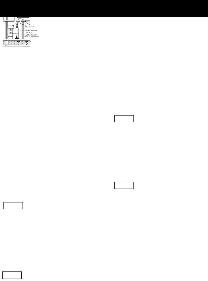
a.ALL AIR FROM INSIDE BUILDINGS: (See Page 7 Figure 1, and Figure 2 below)
The confined space shall be provided with two permanent openings communicating directly with an additional room(s) of sufficient volume so that the combined volume of all spaces meets the criteria for an unconfined space. The total input of all gas utilization equipment installed in the combined space shall be considered in making this determination. Each opening shall have a minimum free area of one square inch per 1,000 Btu per hour of the total input rating of all gas utilization equipment in the confined space, but not less than 100 square inches. One opening shall commence within 12 inches of the top and one commencing within 12 inches of the bottom of the enclosure.
Figure 2
b.ALL AIR FROM OUTDOORS: (see Figures 3-5)
The confined space shall be provided with two permanent openings, one commencing within 12 inches of the top and one commencing within 12 inches from the bottom of the enclosure. The openings shall communicate directly, or by ducts, with the outdoors or spaces (crawl or attic) that freely communicate with the outdoors.
Figure 3
8
1.When directly communicating with the outdoors, each opening shall have a minimum free area of 1 square inch per 4,000 Btu per hour of total input rating of all equipment in the enclosure. (See Figure 3.)
2.When communicating with the outdoors through vertical ducts, each opening shall have a minimum free area of 1 square inch per 4,000 Btu per hour of total input rating of all equipment in the enclosure. (See Figure 4.)
Figure 4
3.When communicating with the outdoors through horizontal ducts, each opening shall have a minimum free area of 1 square inch per 2,000 Btu per hour of total input rating of all equipment in the enclosure. (See Figure 5.)
Figure 5
4.When ducts are used, they shall be of the same cross-sec- tional area as the free area of the openings to which they connect. The minimum short side dimension of rectangular air ducts shall not be less than 3 inches. (See Figure 5.)
5.Louvers and Grilles: In calculating free area, consideration shall be given to the blocking effect of louvers, grilles or screens protecting openings. Screens used shall not be smaller than 1⁄4 inch mesh. If the free area through a design of louver or grille is known, it should be used in calculating the size opening required to provide the free area specified. If the design and free area is not known, it may be assumed that wood louvers will be 20-25 percent free area and metal louvers and grilles will have 60-75 percent free area. Louvers and grilles shall be fixed in the open position or interlocked with the equipment so that they are opened automatically during equipment operation.
6.Special Conditions Created by Mechanical Exhausting or Fireplaces: Operation of exhaust fans, ventilation systems, clothes dryers or fireplaces may create conditions requiring special attention to avoid unsatisfactory operation of installed gas utilization equipment.
 Loading...