


Electronic Digital
Caliper 799A Series
Calibre Electrónico
Digital Serie 799A
Pied à Coulisse Numérique
Électronique Série 799A
Calibro Digitale
Elettronico Serie 799A
Digitaler Messschieber
Serie 799A
799A
Paquímetro Eletrônico
Digital Série 799A
Instruction Manual Manual de Instrucciones Manuel d’instructions Manuale di istruzioni Bedienungsanleitung
Manual de Instruções
1
READ THIS MANUAL BEFORE USING
THE INSTRUMENT
ANTES DE UTILIZAR EL INSTRUMENTO, LEA
ATENTAMENTE ESTE MANUAL
LIRE CE MANUEL AVANT D’UTILISER L’ INSTRUMENT
LEGGERE IL PRESENTE MANUALE
PRIMA DI UTILIZZARE LO STRUMENTO
LESEN SIE DIESE ANLEITUNG BEVOR SIE DEN MESSSCHIEBER BENUTZEN
ANTES DE UTILIZAR O INSTRUMENTO, LEIA
ATENTAMENTE ESTE MANUAL
2
7 13 5 8
2
10
4 
1 |
12 |
14 |
9 |
11 |
6 |
3 |
|
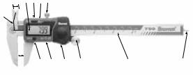
1 - Jaws for external measurement |
5 - Slide |
- Patas para medición de exteriores |
- Cursor |
- Mâchoires pour mesures extérieures |
- Coulisse |
- Ganasce per misurazione di esterni |
- Corsoio |
- Messschenkel für Außenmessung |
- Schieber |
- |
- |
- Faces para medição externa |
- Cursor |
2 - Jaws for internal measurement |
6 - Graduated scale |
- Patas para medición de interiores |
- Escala graduada |
- Mâchoires pour mesures intérieures |
- Barre graduée |
- Ganasce per misurazione di interni |
- Scala graduata |
- Messschenkel für Innenmessung |
- Schiene mit Strichskala |
- |
- |
- Faces para medição interna |
- Escala graduada |
3 - Depth measuring rod |
7 - LCD display |
- Varilla para medición de profundidad |
- Visualizador de cristal líquido |
- Tige de profondeur |
- Affichage à cristaux liquides |
- Asta di misurazione della profondità |
- Display LCD |
- Tiefenmessstange |
- Display |
- |
- LCD |
- Haste para medição de profundidade |
- Mostrador de cristal líquido |
4 - Scribing face |
8 - Slide locking screw |
- Superficie de trazado |
- Tornillo de fijación del cursor |
- Face de traçage |
- Vis de blocage de la coulisse |
- Superficie di tracciatura |
- Vite di bloccaggio corsoio |
- Anreißfläche |
- Feststellschraube |
- |
- |
- Superfície para traçagem |
- Parafuso de fixação do cursor |
3

9 - Battery cover |
12 - “Zero” set button |
|
- Tapa de la batería |
- Botón para hacer “Cero” - ZERO |
|
- Couvercle de pile |
- Bouton de remise à “zéro” |
|
- Coperchio batteria |
- Pulsante “zero” |
|
- Batteriefachdeckel |
- Nullpunkteinstellung “Zero” |
|
- |
- “ ” |
|
- Tampa da bateria |
- Botão de zeragem “ZERO” |
|
10 - Scribing reference face |
13 - “mm/IN” button |
|
- Superficie de referencia para trazado |
- Botón de conversión pulgada/ |
|
- Surface de référence pour le traçage |
milímetro “mm/IN” |
|
- Superficie di tracciatura di |
- Bouton “mm/po” |
|
riferimento |
- Pulsante “mm/IN” |
|
- Stufenmessschenkel |
- Umschaltung “Zoll / mm” |
|
- |
- “ ” |
|
- Superfície de referência para |
- Botão de conversão polegada/ |
|
traçagem |
milímetro “mm/IN” |
|
11 - Fine adjustment thumb roll |
14 - Power “on/off” button |
|
- Rodillo de ajuste fino |
- Botón encendido/apagado “on/off” |
|
- Bouton de réglage précis |
- Bouton “marche/arrêt” “on/off” |
|
- Rotella per l’accostamento fine |
- Pulsante di alimentazione “on/off” |
|
- Feineinstellung |
- An/Aus-Taste “on/off” |
|
- |
- “ / ” |
|
- Roldana para ajuste fino |
- Botão liga/desliga “on/off” |
|
NOTE: The pictures shown are |
HINWEIS: |
Die gezeigten Bilder |
illustrative; the components may |
haben nur |
Beispielcharakter; die |
vary according to the model. |
Bauteile variieren von Modell zu |
|
Obs.: Las figuras aquí presentadas |
Modell. |
|
|
|
|
son ilustrativas, los componentes pueden cambiar conforme el modelo del instrumento.
NOTE: Les illustrations permettent de fournir des explications; les composantes peuvent varier selon les modèles.
NOTA: le figure sono solo a scopo illustrativo; i componenti possono variare a seconda del modello.
: .
Obs.: As figuras aqui apresentadas são ilustrativas, os componentes podem variar conforme o modelo do instrumento.
4

Electronic Digital Caliper
799A Series
Characteristics
|
Millimeter |
Inch |
Range |
|
|
mm (inch) |
|||
|
|
|
||
Resolution (1) |
0,01 |
0,0005 |
Up to 300 (12”) |
|
Accuracy (2) |
± 0,02 |
± 0,001 |
Up to 100 (4”) |
|
± 0,03 |
± 0,001 |
> 100 (4”) up to 300 (12”) |
||
|
(1)Resolution: Smallest difference between indications of a displaying device that can be meaningfully distinguished. For a digital displaying device, this is the change in the indication when the least significant digit changes by one step (VIM).
(2)Accuracy: Closeness of the agreement between the result of a measurement and a true value of the measurand (VIM).
P.S.: VIM - International Metrology Vocabulary
■■ Set zero at any position of the slide. ■■ Power on/off button.
■■ Automatic on when moving the slide.
■■ Automatic off after seven minutes of non-use to save the battery life. ■■ Off at any position of the slide; the last zero will be kept.
■■ LCD display with active unit system: millimeter “mm” or inch “in”. ■■ Lithium battery 3V CR2032.
5
Precautions when using the Caliper
■■ Do not measure a rotating part; it is dangerous and causes the faces in contact to wear.
■■ Do not expose the caliper to direct sunlight or extreme temperatures.
■■ Do not apply any voltage on any part of the caliper. Any external voltage may damage the circuitry of the caliper.
■■ Do not disassemble the caliper.
■■ Do not move the slide too fast (over 1,5m/s or 60 inches/s), this can cause measurement errors.
■■ Flashing of digits shows a weak battery and that it must be replaced. ■■ Do not wash or immerse the caliper in any liquid.
■■ When cleaning the caliper, use a fabric lightly wet in isopropyl alcohol. ■■ Keep the caliper clean and dry.
■■ Avoid handling the caliper with oily hands.
6
Operating Instructions
■■ Install the battery that comes with the instrument. See item “Installation/ Replacement of battery”. Once installed the caliper will come on automatically.
■■ To select the measurement unit needed, press the “mm/IN” button (13). ■■ To move the slide (5) loosen the slide locking screw (8). Use the thumb
roll (11) to move the slide.
■■ Check to see if the buttons “zero” (12) and “mm/IN” (13) respond well. Digital display must be stable and display at any position within the whole range.
■■ Clean the measuring faces with a lint-free cloth or chamois.
■■ External measurement: Close the jaws and press the “zero” button (12) to reset the display to zero (fig. 1A ). Put the part to be measured as close as possible to the scale (6) (fig. 1B) and adjust the measuring faces (1) to the part surface (fig. 1C). Do not apply excessive pressure when measuring (fig. 2).
■■ Internal measurement: Close the jaws and press the “zero” button (12) to reset the display to zero (fig. 3A). Introduce the internal measuring jaws (2) as deep as possible inside the part and adjust the measuring faces to the part surface (fig. 3B). To obtain the measurement of an internal diameter see fig. 3C and to obtain the measurement value inside a slot see fig. 3D.
■■ Depth measurement: Close the jaws and press the “zero” button (12) to reset the display to zero (fig. 4A). Keep the depth measuring rod (3) perpendicularly to the part bottom (fig. 4B & 4C).
■■ Cam measurement: Close the jaws and press the “zero” button (12) to reset the display to zero (fig. 5A). Open the jaws in a little bigger dimension than the cam, place the scribing face (4) against the bottom of the cam and approach the scribing reference face (10) until the part surface. The cam value will be shown on the display (fig. 5B).
7
Operating Instructions
■■ Scribing face: Close the jaws and press the “zero” button (12) to reset the display to zero (fig. 6A). Adjust the scribing reference face (10) to the part reference, slide the cursor (5) to the chosen measurement, lock it using the locking screw (8) and then scribe (fig. 6B).
■■ Measurement for comparison: Using a standard, press the “zero” button (12) to reset the display to zero (fig. 7A). After that, start measuring; the variation will be shown on the display. Dimensions smaller than standard will be indicated with a negative sign (fig. 7B).
■■ Measurement of center to center between holes or identical pins: Using one of the holes or one of the pins as a reference, press the “zero” button (12) to reset the display to zero (fig. 8A & 9A). After that, start measuring; the center to center value will be shown on the display (fig. 8B & 9B).
■■ Measurement of wall thickness: Using a part as reference place the caliper and press the “zero” button (12) to reset the display to zero (fig. 10A). Next, measure the depth using the depth measuring rod (3). The thickness will be shown on the display (fig. 10B).
■■ Measurement in places where reading is difficult to obtain: Measure and press the “zero” button (12) to reset the display to zero (fig. 11A). After that, close the jaws; the measurement will be shown on the display with a negative sign (fig. 11B) (Do not consider the sign).
8

Installation / Replacement of battery
Remove the battery cover (9) by sliding it in the arrow direction, then lift it. Install or replace the battery making sure that the positive pole faces up, and slide the cover back into place.
Troubleshooting
Failure |
Cause |
Solution |
|
|
|
Five digits flash |
Low battery. |
Replace the battery. |
simultaneously, about |
|
|
once per second. |
|
|
Display does not change |
Trouble with the |
Remove the battery |
when the slide is moved. |
electronic circuitry. |
and reinstall after 30 |
|
|
seconds. |
Less accurate than |
Contamination on the |
Clean the scale. If |
specified or electronic |
sensor. |
the problem remains, |
system failure. |
|
contact your distributor. |
|
|
|
No display on LCD. |
1 - Battery in poor |
1 - Remove the battery |
|
contact. |
cover and reseat the |
|
|
battery to insure a good |
|
2 - Low battery. |
connection. |
|
|
2 - Replace the battery. |
|
|
|
* THIS IS AN UNCONTROLLED COPY SO THAT THE PRODUCT MAY BE MODIFIED AT ANY TIME WITHOUT PRIOR NOTICE.
9
10
Calibre Electrónico Digital
Serie 799A
Características
|
Milímetro |
Pulgada |
Rango de Medición |
|
|
mm (pulgada) |
|||
|
|
|
||
Resolución (1) |
0,01 |
0,0005 |
Hasta 300 (12”) |
|
Precisión (2) |
± 0,02 |
± 0,001 |
Hasta 100 (4”) |
|
± 0,03 |
± 0,001 |
> 100 (4”) hasta 300 (12”) |
||
|
(1)Resolución: Menor diferencia en la indicación de un dispositivo mostrador que puede ser percibida. Para dispositivo digital es la variación en la indicación cuando el dígito menos significativo varía una unidad (VIM).
(2)Precisión: Aptitud de un instrumento de medición para dar respuestas próximas a un valor verdadero (VIM).
OBS. : VIM - Vocabulario Internacional de Metrologia
■■ Cero en cualquier posición del cursor. ■■ Botón encendido/apagado “ON/OFF”.
■■ Enciende automáticamente moviendo el cursor.
■■ Desconexión automática después de 7 minutos sin uso para economía de la batería.
■■ Una vez hecho cero, el calibre puede apagarse y el cero se mantendrá.
■■ Visualizador de cristal líquido con indicador de sistema de unidades usado: milímetro “mm” o pulgada “in”.
■■ Batería de Lithium 3V CR2032.
11
Cuidados en la utilización del Calibre
■■ No hacer mediciones en piezas en movimiento, esto es peligroso y provoca desgaste en las superficies de contacto.
■■ No exponer el calibre a la luz directa solar o a grandes variaciones de temperatura.
■■ Evitar el contacto del calibre con cualquier fuente de electricidad. Cualquier descarga eléctrica puede quemar o dañar el circuito interno.
■■ No desmontar el calibre.
■■ Evitar mover el cursor a alta velocidad (por encima de 1,5m/s ó 60 pul/s), esto causará error de medición.
■■ Sí el visualizador empieza a parpadear indica que la batería debe ser sustituida.
■■ No lavar o sumergir el calibre en líquidos.
■■ Para la limpieza general del calibre utilizar un tejido levemente mojado con alcohol “isopropílico”.
■■ Mantener el calibre siempre limpio y seco.
■■ Evitar el manoseo del calibre con las manos sucias de aceite.
12
Instrucciones de utilización
■■ Instale la batería que acompaña el instrumento. Ver ítem “Instalar / Sustituir la batería”.
■■ Para seleccionar la unidad de medida, milímetro o pulgada, presione el botón “mm/IN” (13).
■■ Para mover el cursor (5) suelte el tornillo de fijación (8). Utilice el rodillo (11) para moverlo.
■■ Verifique el funcionamiento de los botones “ZERO” (12) y de conversión “mm/IN” (13). La indicación en el visualizador debe ser estable y continua en cualquier posición del cursor.
■■ Limpie las patas de medición con tejido suave o gamuza.
■■ Medición de exteriores: cierre el calibre y presione el botón ZERO (12) hasta que en el visualizador muestre cero (Fig. 1A). Posicione la pieza a ser medida lo más cerca posible de la regla (6) (Fig. 1B) y haga que las patas de medición (1) se ajusten perfectamente a la pieza (Fig. 1C). Cuidado, no aplicar excesiva presión en la medición (Fig. 2).
■■ Medición de interiores: con las patas cerradas presione el botón “ZERO” (12) hasta que en el visualizador muestre cero (Fig. 3A). Introduzca las patas de medición de interiores (2) lo más profundo posible en la pieza (Fig. 3B). Para obtener una medición de un diámetro interno ver Fig. 3C y para obtener una medición de una ranura ver Fig. 3D.
■■ Medición de profundidad: con las patas cerradas presione el botón “ZERO” (12) hasta que en el visualizador muestre cero (Fig. 4A). Posicione la varilla para medición de profundidad (3) perpendicular al fondo de la pieza (Fig. 4B y 4C).
■■ Medición de resaltes: con las patas cerradas presione el botón “ZERO” (12) hasta que en el visualizador muestre cero (Fig. 5A). Abra el calibre en una medida ligeramente superior a la profundidad de resalte, apoye la superficie de trazado (4) al fondo de ese resalte y acerque la superficie de referencia para trazado (10) en la superficie de la pieza. El valor del resalte aparecerá en el visualizador (Fig. 5B).
13
Instrucciones de utilización
■■ Superficie de trazado: con las patas cerradas presione el botón “ZERO” (12) hasta que en el visualizador muestre cero (Fig. 6A). Apoye la superficie de referencia para trazado (10) en la superficie de referencia de la pieza, desplace el cursor (5) a la medida deseada, trabe el cursor por medio del tornillo de fijación (8) y haga el trazado (Fig. 6B).
■■ Medición por comparación: con un patrón estándar, presione el botón “ZERO” (12) hasta que en el visualizador muestre cero (Fig. 7A). Ahora puede medir; la desviación se muestra en el visualizador. Las dimensiones menores que el patrón aparecerán con un signo (-) delante del valor (Fig. 7B).
■■ Medición entre pines o centros de agujeros: utilizando uno de los agujeros o uno de los pines como referencia, presione el botón “ZERO” (12) hasta que en el visualizador muestre cero (Fig. 8A y 9A). Ahora puede medir. La distancia entre centros aparecerá en el visualizador (Fig. 8B y 9B).
■■ Medición de espesor de pared: utilizando la pieza como referencia, posicione el calibre y presione el botón “ZERO” (12) hasta que en el visualizador muestre cero (Fig. 10A). Ahora puede medir usando la varilla para medición de profundidad (3). El espesor aparecerá en el visualizador (Fig. 10B).
■■ Medición en lugares de difícil lectura: haga la medición y presione el botón “ZERO” (12) hasta que en el visualizador muestre cero (Fig. 11A). Después cierre las patas, ahora se muestra la medida en el visualizador con un signo negativo (Fig. 11B). (No considerar el signo).
14

Instalar / Sustituir la batería
Saque la tapa de la batería (9) deslizándola en el sentido de la flecha, enseguida levántela. Instale o sustituya la batería de manera que el polo positivo se quede para arriba; recoloque la tapa.
Problemas eventuales
Fallo |
Motivo |
Solución |
|
|
|
Los cinco dígitos |
Batería baja. |
Sustituir la batería. |
parpadean |
|
|
simultáneamente en |
|
|
intervalos de 1 segundo. |
|
|
|
|
|
El visualizador no |
Problema accidental en |
Retirar la batería y |
cambia cuando el cursor |
el circuito. |
recolocarla después de |
se mueve. |
|
30 segundos. |
Precisión en desacuerdo |
Suciedad en el sensor. |
Limpiar la escala |
con la especificada |
|
del instrumento. |
o falla en el sistema |
|
Persistiendo el |
electrónico. |
|
problema, contacte su |
|
|
distribuidor. |
El calibre no funciona. |
1 - Batería con mal |
1 - Retirar la tapa de |
|
contacto. |
la batería y verificar |
|
|
el compartimiento |
|
2 - Batería baja. |
manteniendo un buen |
|
|
contacto. |
|
|
2 - Sustituir la batería. |
* ESTE EJEMPLAR ES UNA COPIA NO CONTROLADA Y EL PRODUCTO PUEDE SER ALTERADO A CUALQUIER MOMENTO, SIN PREVIO AVISO.
15
 Loading...