


User Manual
2900 Series Electronic Indicator
starrett.com

2900 Indicator User Manual |
|
|
Table of Contents |
|
|
Guidelines for Indicator Care.......................................................................... |
|
2 |
Operating Instructions................................................................................... |
|
3 |
Indicator Components, Dimensions & Layout................................................. |
3 |
|
Button Functions........................................................................................... |
|
4 |
2900 Indicator Models, Feature Level & Resolution........................................ |
5 |
|
Resolution Selection*..................................................................................... |
|
5 |
Setting the PRESET Function*........................................................................ |
|
6 |
Setting MIN/MAX Limits (Go/No Go)**............................................................ |
|
6 |
Displaying MIN/MAX/TIR Values**.................................................................. |
|
8 |
Lock Mode*................................................................................................... |
|
8 |
Data Output Connection................................................................................. |
|
9 |
Battery Installation........................................................................................ |
|
9 |
Appendix A: Technical Specifications........................................................... |
|
10 |
Appendix B: Serial Output Connector........................................................... |
|
11 |
*Available with Standard & Advanced Features |
. ** Available only with Advanced Features |
|
Guidelines for Indicator Care
1.Avoid dropping the indicator.
2.Avoid extreme temperatures and direct sunlight for extended periods.
3.Avoid contact with liquids and dusty environments.
4.Avoid shocks to the contact point and spindle.
5.Do not apply radial force to the spindle.
6.If the indicator is stem-mounted, protect it from being hit or bumped to avoid stem/case mechanical alignment damage.
7.Do not over-tighten the mounting mechanism. If possible, use clamp mounting rather than set screws to prevent damage to the spindle.
8.Clean the spindle frequently with a dry cloth or a chamois to prevent sluggish or sticky movement. Isopropyl alcohol may be used to remove gummy deposits on metallic parts. Do not apply lubricant to the spindle or use solvents.
9.Do not disassemble or modify the indicator.
2
2900 Indicator User Manual
Operating Instructions
1.Install batteries (included with indicator).
2.Lightly clean the contact point.
3.Secure the indicator to an appropriate holding device.
4.Press the ON/OFF button to turn the indicator on.
5.Select the unit of measure (inch or millimeter) by pressing the IN/mm button. (Not applicable to metric indicator models).
6.Place the indicator perpendicular to the reference surface being measured. Allow enough movement to be able to take a higher or lower measurement.
7.Press the ZERO button to reset the display.
8.Lift the spindle, remove the reference surface and place the work piece to be measured. Put the spindle carefully on to its surface. The measured value will be shown on the LCD.
9.Press and hold the ON/OFF button to turn the indicator off. If left unattended, it will turn off automatically in 30 minutes.
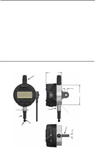
Indicator Components, Dimensions & Layout
|
|
|
|
1-21/32" |
|
Stem Cap |
|
|
(42.2mm) |
|
|
|
|
|
|
|
|
|
1/4" |
|
|
|
|
(6.5mm) |
|
|
|
|
2-5/64" (53mm) |
3/8" (9.5mm) |
|
|
Stem |
Data |
|
|
|
|
|
Spindle |
|
Data |
|
Output |
|
|
Cover |
||
Bellows |
|
Cable |
|
|
|
|
|
Contact Point |
Spindle |
Back Lug |
|
||
|
1/4" |
|
|
|
|
|
|
(6.5mm) |
|
|
Battery |
|
|
Drawer |
starrett.com |
3 |
2900 Indicator User Manual
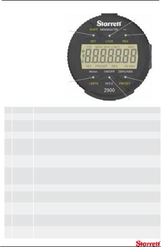
Button Functions
LOCK, RES, LIMITS and PRESET, printed in yellow, are used in conjunction with the SHIFT 5 button.
To engage press the SHIFT button first. The SET icon will appear on the bottom left corner. Then press
the button for the desired function.
6 & 12
2 & 7
|
|
4 & 8 |
3, 9 & 10 |
|
|
1 & 11 |
|
1 |
ON/OFF |
Power button. Press and hold for 4 seconds. |
|
2 |
+/- |
Plus/Minus sets the direction of the reading |
|
3 |
ZERO |
Half a second after releasing the ZERO button the display will zero. Do |
|
|
|
not move from zero during that half second. |
|
4 |
IN/mm |
Toggles the display between English or Metric modes. |
|
5 |
SHIFT/SET |
Dual function. To enable the Lock, Resolution Selection, Preset or |
Limits |
|
|
(Go/No Go) function. When enabled, SET icon will show in the bottom left |
|
|
|
corner of the display. |
|
6 |
LOCK |
Prevents operator modification to the Settings. Press SHIFT/SET button, |
|
|
|
then press and hold the LOCK button (after setting the other functions). |
|
7 |
RES |
Resolution. First select the Unit (English/Metric). Press SHIFT/SET then |
|
|
|
the RES (Plus/Minus) buttons. Press the RES button to scroll through |
|
|
|
choices and press the SHIFT/SET to make the selection. |
|
8 |
LIMITS |
Sets the Min and Max values for the Go/No Go function. |
|
9 |
PRESET |
Press the SHIFT/SET button then press the PRESET button to enable the |
|
|
|
PRESET function. |
|
10 |
ZERO/ABS |
Dual Function. Press and hold for two seconds to activate the ABS mode |
|
|
|
or to exit the ABS mode. To zero the display, see #3 above. |
|
11 |
HOLD |
Press HOLD momentarily to capture a reading. The captured reading will |
|
|
|
flash on and off. To disable, press the HOLD button again. |
|
12 |
MIN/MAX/ |
Displays the minimum or maximum values captured during operation. |
|
|
TIR |
The TIR function displays the difference between the captured readings. |
|
4
 Loading...