


Altissimo®
Electronic Height Gage
Operation Manual

Contents
Introduction ..................................................................................................................................................... |
2 |
Unpacking........................................................................................................................................................ |
3 |
Setup ................................................................................................................................................................ |
4 |
Probe Calibration............................................................................................................................................. |
5 |
Establishing a Datum....................................................................................................................................... |
6 |
Measuring Modes |
|
-Measuring - Height ......................................................................................................................... |
7 |
-Measuring – Center .......................................................................................................................... |
8 |
-Measuring - Diameter ..................................................................................................................... |
9 |
-Measuring – TIR ............................................................................................................................ |
10 |
Continuous Display and Scribing Mode ........................................................................................................ |
11 |
Setup Modes .......................................................................................................................................... |
12 - 14 |
Data Output ................................................................................................................................................... |
15 |
Symbols ................................................................................................................................................. |
16 - 17 |
Specifications ................................................................................................................................................ |
18 |
Care and Maintenance |
|
-Charging and Replacing Batteries.................................................................................................. |
19 |
-Cleaning ................................................................................................................................. |
20 - 21 |
Troubleshooting |
|
- Error Messages.............................................................................................................................. |
22 |
Accessories and Replacement Order Information ......................................................................................... |
23 |
The L.S. Starrett Company
121 Crescent Street
Athol, MA 01331 U.S.A.
The L.S. Starrett Company assumes no liability to any party for any loss or damage, direct or indirect, caused by use of this gage that is not in accordance with the instructions in this manual. Details of this document are subject to change without notice.
Rev. K - Oct 2010
Starrett Altissimo Operation Manual |
Page 1 |
CAT 2000-24 |

Introduction
The Starrett Altissimo is a revolutionary new measuring instrument. It combines the simplicity and ease-of-use of mid-priced height gages with the features and performance of high-end height gages.
It is an easy to use height gage with a dynamic probe that allows both point and scanning measurements. It provides direct calculation of Heights, Centers, Diameters, Max, Min and TIR as well as Distance Between Points and Distance to Last Feature. The Altissimo® can also be used for Scribing.
Starrett Altissimo Operation Manual |
Page 2 |
CAT 2000-24 |
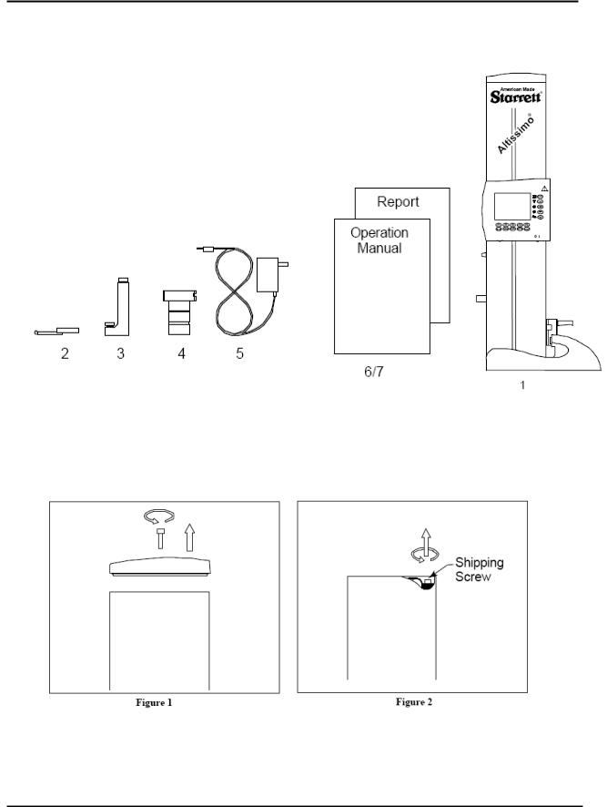
Unpacking
Checking Contents
The Altissimo is delivered in a Cardboard Box that is specially fitted to provide protection from the shock, vibration and moisture normally encountered during shipments. Keep this box for storage and future shipments of the tool.
Carefully check the contents to ensure that all items are there:
1.Height Gage
2.Probe, Ø.1875”
3.Probe Holder
4.Calibration Block
5.Wall Mounted AC Adapter/Battery Charger
6.Operation Manual
7.Report
a.) |
With the 2000-24 a Letter of Certification is supplied. |
b.) |
With the 2001-24 an Inspection Report is supplied. |
Unpacking
1.Lay the Box on a flat surface and open. Remove accessories.
2.Place the Altissimo carefully on a work surface and remove the plastic bag.
3.Wipe the bottom of the base before placing on a Surface Plate.
4.Use a 3/16” Hex Wrench to remove the Top Cover. (See Figure 1)
5.Use a 5/32” Hex Wrench to remove the Counterbalance Shipping Screw. (See Figure 2) Replace the screw in the tapped hole next to the one from which it was removed.
6.Replace the Top Cover making the screw finger tight. Do Not Over Tighten Screw.
Starrett Altissimo Operation Manual |
Page 3 |
CAT 2000-24 |

Setup
1.Charge Battery - The Altissimo battery was fully charged at the factory, however, the battery may have discharged during shipping and storage. It is recommended to leave the charger connected for at least fourteen hours. The charging circuit is designed to provide a maintenance charge to the battery and may remain connected for the duration of use. The tool will remain ON while the charger is plugged in regardless of the position of the Battery Power ON/OFF Switch.
Removing the Charger plug and reinserting will initiate another charge cycle depending on the state of charge of the battery.
If the Low Battery ICON comes on, locate the charger and plug it into the Power Jack on the right side of the Display. (Figure 3)
See Page 19 for additional Battery Charging information.
CAUTION - See Care and Maintenance section for necessary precautions.
2.Move Slide - Rotate the Probe and Belt Locking Knobs counterclockwise. Using the Coarse Adjuster Knob move the Probe Mounting Arm to the center of travel. Re-lock the Belt and Probe Locking Knobs. (See Figure 4)
3.Mount Probe Holder - Mount the Probe Holder onto the Mounting Arm and tighten the screw firmly. (See Figure 5)
Note: Make sure the Probe Holder is mounted vertically.
4.Mount Probe - Mount the Probe into the Probe Holder and tighten the screw firmly. (See Figure 6)
Note: Make sure the Probe Tip is oriented downward so that the Probe Holder or the Probe Shank does not hit the surface plate.
5.Clean - Clean the Probe Tip and the Top and Bottom measuring surfaces of the Calibration Block with Isopropyl Alcohol and lint free cotton cloth. (See Figure 7)
6.Lifting - Care should be taken when lifting the Altissimo. Lock down the probe and belt (See Figure 4). Firmly grip the unit by the base and outer casing. Avoid all contact with the probe and display panel. Jarring motion may damage the gage. Do not drop.
Starrett Altissimo Operation Manual |
Page 4 |
CAT 2000-24 |
Probe Calibration
Power On - Turn the Power on, if using the Battery for power place the Battery Power On/Off switch to the 1 position or plug the charger in and the unit will power regardless of the Battery Power On/Off Switch position.
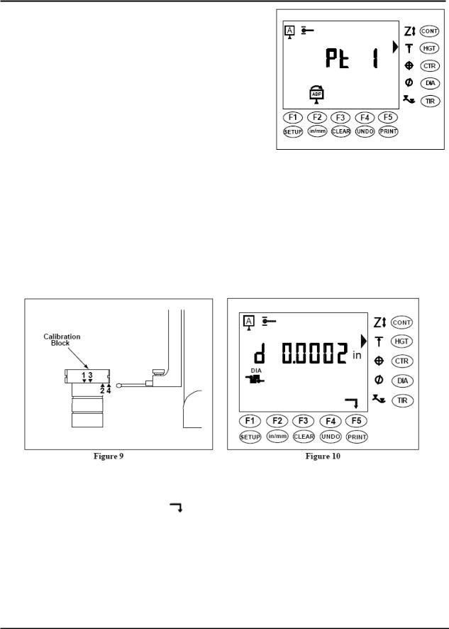
The display comes on in Height Mode and prompts for Point 1 (Pt 1). (See Figure 8)
Note: The Altissimo can be used to measure heights even if the Probe is not calibrated. See Measuring Modes – Height Section.
Figure 8
Probe Diameter Calibration – If the Probe Symbol is Flashing in
the upper left corner of the Display, it will be necessary to Calibrate the Probe Diameter. (See Figure 9) The Probe Diameter must be recalibrated when the Altissimo is first received and periodically thereafter, especially when measuring conditions change.
Press the SETUP Key and the Probe Calibration Mode Icon will light. The display will ask for Point 1 (Cal 1). Position the Calibration Block under the Probe. Using the Coarse Adjuster Knob move the probe down onto the Upper Measuring Surface until the tool beeps. Move the Probe clear of the surface. The display will ask for Point 2 (Cal 2). Similarly measure the Lower Measuring Surface of the Calibration Block. Measure the Upper and Lower Measuring Surface a second time.
Note: In order to calculate the diameter of the probe the first and second measurements must be taken in opposite directions, the third and fourth measurements must also be taken in opposite directions.
Accept the Calibration - After measuring each surface twice, the Altissimo will display a number which is the Deviation of the Probe Calibration. The deviation is the repeatability of the points taken during Probe Calibration. This provides a measure of the quality of the measurements. If the Deviation is sufficiently low, under .0002”
(.004mm), then Press the F5 Function Key ( ) to accept the value. (See Figure 10) The Probe Calibration Icon stops Flashing and the top and bottom "Hit" bars are Flashing indicating measurements can be made in either direction.
Note: If the Deviation is high, over .0002” (.004 mm), then check the tightness of the Probe Arm and Probe. Check the cleanliness of the Probe Tip and Calibration Block. Make sure that the Probe and Belt Locks are fully unlocked. Then recalibrate the Probe.
Important: The Altissimo will store the Calibrated Probe Diameter even after it is turned off. The Probe must be recalibrated each time it is changed or repositioned. See Setup Section for instructions on other Probe Diameter Calibration Options.
Starrett Altissimo Operation Manual |
Page 5 |
CAT 2000-24 |
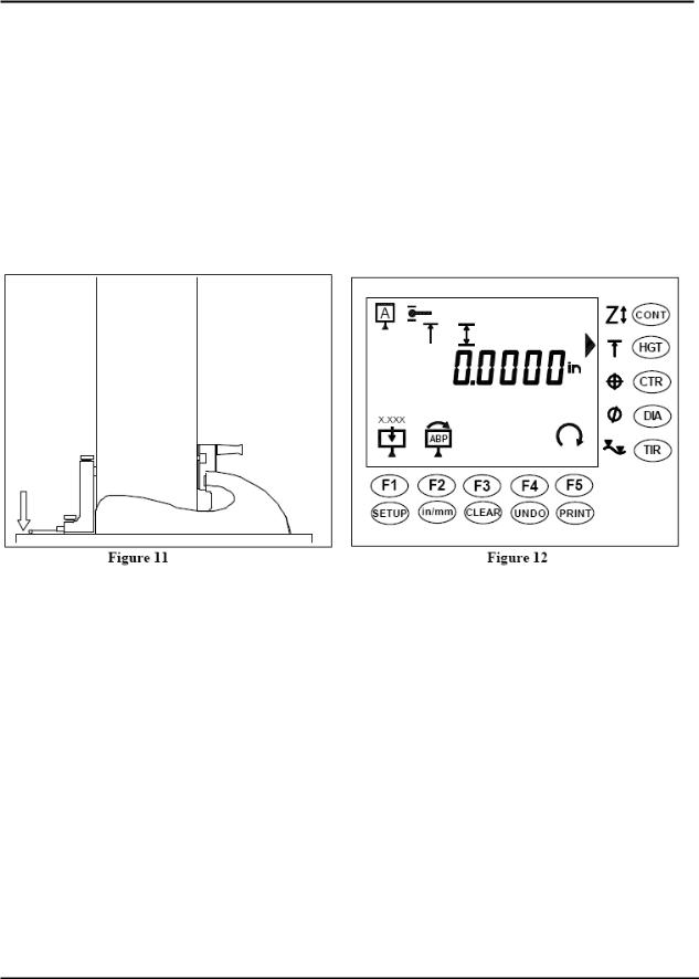
Establishing a Datum
Measure Datum – If the Datum Symbol is flashing in the upper left corner of the Display then a Datum will need to be established. Using the Coarse Adjuster Knob bring the Probe in contact with the surface plate or other datum surface until it Beeps. (See Figure 11) Move the Probe clear of the surface. Press the F1 key to set the Active Datum to 0 at the last measured point. (See Figure 12)
Note: If the probe is not calibrated the Altissimo may be used in the Unidirectional Height mode. Simply take a measurement in either direction, Press the F1 Key to set the Active Datum to 0. The tool will only measure in the direction that the initial point is measured in. See Measuring Modes – Height Section.
If a Datum is already established, then select the appropriate Measurement Mode using the Keys to the right of the Display. Any of the following measurements may be used to establish a Datum: Height, Center, Max or Min. Measure the Datum and verify that the value in the Display is the value to be used for the Datum. If the Diameter or TIR Measurement Mode is selected, it will be necessary to use the Hot Key on the Base or the F5 Key ( ) on the Display to change the Display Value to Center, Max or Min before a Datum can be stored.
Store Datum - Simply press the F1 Key while displaying any of the above measurements and the Active Datum will be set to 0 at the Measured Feature.
Note: Two Datums (A and B) and a Preset (P) may be stored. The Active Datum appears as a letter (A, B or P) in the Datum Symbol in the upper left corner of the display. The Active Datum may be changed at any time by pressing the F2 Key (ABP).
Store Preset – If the Preset is active, a P will appear in the Datum Symbol in the upper left corner of the Display. When the F1 Key is pressed the Preset Value will be displayed. The Preset Value may be changed at this time using the F1 through F4 keys. After verifying that the preset value is correct press the F5 key and the Datum will be set to the Preset Value at the Measured Feature.
Starrett Altissimo Operation Manual |
Page 6 |
CAT 2000-24 |
 Loading...