

Page 1
®
EQ SERIES
High Performance Commercial Pump
Installation
User's Guide
IMPORTANT SAFETY INSTRUCTIONS
READ AND FOLLOW ALL INSTRUCTIONS
SAVE THESE INSTRUCTIONS
and
Page 2

Technical and Customer Support (Europe)
For technical support questions and product service information, contact:
Phone: (0032) 14 25 99 66 - 8 A.M. to 5 P.M. (GMT)
Fax: (0032) 14 25 99 73
Technical and Customer Support (United States)
For technical support questions and product service information, contact:
Sanford, North Carolina (8 A.M. to 5 P.M. - EST)
Moorpark, California (8 A.M. to 5 P.M. - PST)
Phone: (800) 831-7133
Fax: (800) 284-4151
www.pentairpool.com and staritepool.com
CE marking only applies to 50 Hz models:
EQK300, EQK500, EQK750, and EQK1000.
ETL marking only applies to models:
EQW300-1PH and EQW500-1PH.
© 2007 Pentair Water Pool and Spa, Inc. All rights reserved.
This document is subject to change without notice.
1620 Hawkins Ave., Sanford, NC 27330 • (919) 566-8000
10951 West Los Angeles Ave., Moorpark, CA 93021 • (805) 553-5000
The
Pentair Pool Products logo
may be used in this document to refer to either the entities claiming the marks and names or their products. Pentair Water Pool and Spa, Inc. disclaims
any proprietary interest in trademarks and trade names other than its own.
P/N 350061 Rev. G 06/26/07
and EQ Series are registered trademarks of Pentair Water Pool and Spa, Inc. Other trademarks and trade names
Page 3

Table of Contents
Important Safety Precautions .............................................................................................. ii
Section 1: Introduction ..................................................................................................... 1
EQ Series Pump Overview ..................................................................................... 1
General Features.....................................................................................................2
Section 2: Installation ....................................................................................................... 3
Installing the EQ Series Pump ................................................................................. 3
Mechanical Installation ............................................................................................3
Pressure Testing ...................................................................................................... 5
Section 3: Electrical Requirements .................................................................................7
Electrical Requirements and Field Wiring ................................................................ 7
Section 4: Initial Operation of Pump ...............................................................................9
Priming the EQ Series Pump................................................................................... 9
i
Section 5: Maintenance .....................................................................................................11
Cleaning the Strainer Basket ................................................................................... 11
Preventative Maintenance .......................................................................................12
Section 6: Servicing .......................................................................................................... 13
Disassembling .........................................................................................................14
Assembling .............................................................................................................. 15
Section 7: Troubleshooting .............................................................................................. 16
Section 8: Replacement Parts ..........................................................................................17
Section 9: Pump Technical Data....................................................................................... 18
Pump Curves ..........................................................................................................18
Engineering Specifications ...................................................................................... 19
Dimensional Data ....................................................................................................20
EQ Series Pump Installation and User’s Guide
Page 4
ii
IMPORTANT SAFETY PRECAUTIONS
Important Notice:
This guide provides installation and operation instructions for the EQ Series Pump.
Consult Pentair Water with any questions regarding this equipment.
Attention Installer: This guide contains important information about the installation, operation and safe use of
this product. This information should be given to the owner and/or operator of this equipment after installation
or left on or near the pump.
Attention User: This manual contains important information that will help you in operating and maintaining
this pump. Please retain it for future reference.
WARNING — Before installing this product, read and follow all warning notices and instructions which
are included. Failure to follow safety warnings and instructions can result in severe
injury, death, or property damage. Call (800) 831-7133 (US) or 0032-14-259900
(Europe) for additional free copies of these instructions.
Consumer Information and Safety
The EQ Series pumps are designed and manufactured to provide many years of safe and reliable service when
installed, operated and maintained according to the information in this manual and the installation codes referred
to in later sections. Throughout the manual, safety warnings and cautions are identified by the “ “ symbol.
Be sure to read and comply with all of the warnings and cautions.
DANGER — Risk of electrical shock or electrocution.
This pool pump must be installed by a licensed or certified electrician or a qualified
pool serviceman in accordance with the National Electrical Code and all applicable
local codes and ordinances. Improper installation will create an electrical hazard which
could result in death or serious injury to pool users, installers, or others due to
electrical shock, and may also cause damage to property.
Always disconnect power to the pool pump at the circuit breaker before servicing the
pump. Ensure that the disconnected circuit is locked out or properly tagged so that it
cannot be switched on while you are working on the pump. Failure to do so could result
in serious injury or death to serviceman, pool users or others due to electric shock.
WARNING — Do not operate the pump until you have read and understand clearly all the operating
instructions and warning messages for all equipment that is a part of the pool
circulating system. The following instructions are intended as a guide for initially
operating the pump in a general pool installation, however each installation may have
unique conditions where the starting procedure could be different. Failure to follow all
operating instructions and warning messages can result in property damage or severe
personal injury or death.
EQ Series Pump Installation and User’s Guide
Page 5
IMPORTANT SAFETY PRECAUTIONS (continued)
WARNING — Never exceed the maximum operating pressure or temperature limits of the system
components. Pumps installed with the EQ Strainer Pot Assembly should not be tested at a
pressure that exceeds the value written on the EQ Strainer Pot. See the Owner's Manual
that accompanies that product for more instructions. Ensure that pressures higher than
those required in the pressure test cannot inadvertently be applied to the circulation
system. This may require the use of a pressure regulator between the water supply and the
circulation system.
Changes in temperature or barometric pressure can cause the internal test pressure to
increase or decrease over time once the system is isolated. A pressure relief device
should be installed that would prevent the pressure from exceeding the intended test
pressure. Exceeding these limits could result in a component failing under pressure. This
instantaneous release of energy can cause failed components to be accelerated to high
velocities and to travel distances of 100 feet or more. These components could cause
severe personal injury or death if they were to strike a person.
WARNING — Due to the potential risk that can be involved it is recommended that the pressure test be
kept to the minimum time required by the local code. Do not allow people to work around
the system when the circulation system is under pressure test. Post appropriate warning
signs and establish a barrier around the pressurized equipment. If the equipment is located
in an equipment room, lock the door and post a warning sign.
iii
Never attempt to adjust any closures or lids or attempt to remove or tighten bolts when the
system is pressurized. These actions can result in a separation or failure of system
components. This instantaneous release of energy can cause components to be
accelerated to high velocities and to travel distances of 100 feet or more. These
components could cause severe personal injury or death if they were to strike a person.
CAUTION — This pump is for use with permanently installed pools and may also be used with hot tubs
and spas if so marked. Do not use with storable pools. A permanently installed pool is
constructed in or on the ground or in a building such that it cannot be readily disassembled
for storage. A storable pool is constructed so that it may be readily disassembled for
storage and reassembled to its original integrity.
EQ Series Pump Installation and User’s Guide
Page 6
iv
IMPORTANT SAFETY PRECAUTIONS (continued)
General Installation Information
WARNING — Pumps improperly sized or installed or used in applications other than for which the pump
was intended can result in severe personal injury or death. These risks may include but not
be limited to electric shock, fire, flooding, suction entrapment or severe injury or property
damage caused by a structural failure of the pump or other system component.
WARNING — The pump can produce high levels of suction within the suction side of the plumbing
system. These high levels of suction can pose a risk if a person comes within the close
proximity of the suction openings. A person can be seriously injured by this high level of
vacuum or may become trapped and drown. It is absolutely critical that the suction
plumbing be installed in accordance with the latest national and local codes for swimming
pools.
• These instructions contain information for a variety of pump models and therefore some instructions may
not apply to a specific model. All models are intended for use in swimming pool applications. The pump will
function correctly only if it is properly sized to the specific application and properly installed.
• The pump is available with or without a specially designed strainer pot assembly. If a suction strainer pot
assembly is to be provided, it should comply with NSF-50 standards. Pumps without the strainer pot
assembly are not self-priming and must be installed so that the pump is always flooded with water. If the
pump is to be installed without a strainer pot, plumbing suction inlets must prevent debris larger tha
0.6 cm ( ¼”) in diameter from being drawn into the pump.
• Pumps installed with the specially designed strainer pot assembly are self-priming at heights up to
3 meters (10 feet) depending on the specific installation.
EQ Series Pump Installation and User’s Guide
Page 7
Section 1
Introduction
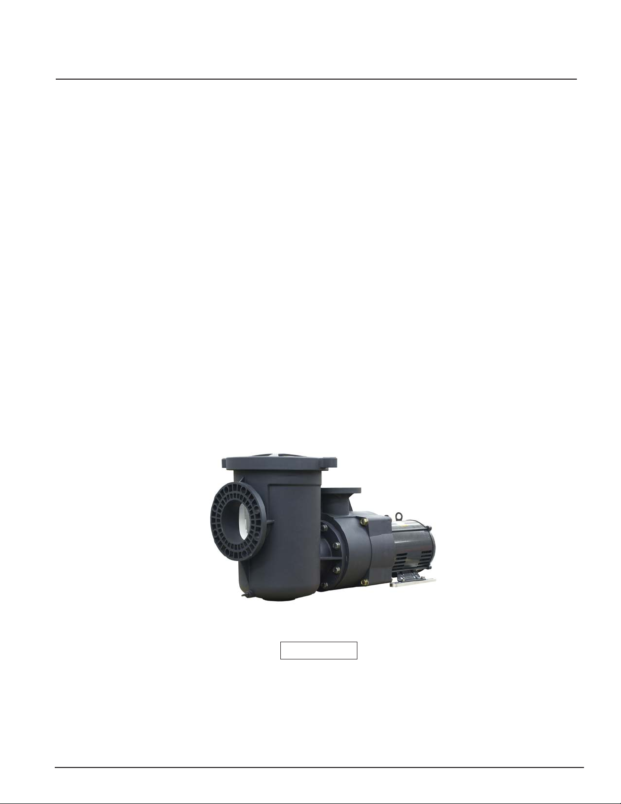
EQ Series® High Performance Commercial Pump Overview
The EQ Series pumps deliver extraordinary performance in every key aspect. They're built to last, of
course, and are also built to be incredibly efficient, quiet, lightweight and corrosion-resistant. All of this adds
up to a pump that is highly cost effective and suited for a wide range of commercial water applications.
At the heart of the EQ's extraordinary performance is its unique impeller design. It provides two significant
benefits. First, it means more efficient performance — the EQ pump moves more water more quickly than
comparable pumps. And secondly , it means the pump's motor doesn't have to work as hard and, as a result,
runs cooler and lasts considerably longer.
What's more, the Pentair EQ pump has been through a rigorous design, development and testing program
so you know it's built to handle the toughest commercial applications for years to come.
1
A vailable in single and three-phase, 50 and 60 Hz models, the EQ sets the new standard for performance in
pumps. No one else in the industry has made a plastic injection-molded pump with performance like this for
pool and water applications.
EQ Series Pump
Patent Pending
EQ Series Pump Installation and User’s Guide
Page 8

2
General Features
• EQ Series = Energy Efficient and Quiet
• Designed in every detail for maximum efficiency
• The only non-corrosive, all-plastic pump designed exclusively for the commercial pool and water applications market
• The EQ impeller features an exclusive design that provides true breakthrough performance
• Lower load due to efficient impeller design means longer motor life
• Cam and Ramp™ lid design with clear lid for added convenience in servicing
Additional Features:
• Closed coupled for quiet stable flow operation
• Lightweight
• 15.24 cm (6") suction and 10.16 cm (4") discharge with strainer pot
• Closed impeller for longer motor life
• Heat-resistant seal operates at up to 66 C° (150° F)
• Bolt-on strainer pot
• Easy one-man installation
• Self-priming pump
• NSF-Listed
• Models available for water feature applications
• CE - Conforms with all health, safety and environmental protection standards of the Eurpoean Union.
Applies to 50 Hz models only .
• Metric flange kit available separately:
• A-EQ-160: Metric fange kit, suction side EQ pump, piping 160mm
• A-EQ-125: Metric fange kit, discharge side EQ pump, piping 125mm
• A-EQ-160B: Metric fange kit, suction side EQ pump, piping 160mm for version without strainer pot.
EQ Series Pump Installation and User’s Guide
Page 9

Section 2
Installation
The following general information describes how to install the EQ Series pump.
Note: Before installing this product, read and follow all warning notices and instructions starting
on page ii.
Installing the EQ Series Pump
Only a qualified service person should install the EQ Series pump.
Mechanical Installation and Pressure Testing
Mechanical Installation
1. Carefully remove the pump unit and strainer pot assembly, if included, from its shipping package.
3
2. The pump will perform best when the suction and return head losses (Total Dynamic Head (TDH)) of the pool
system have been carefully determined and the correct pump model selected to fit these requirements. A pump
should be selected to operate near the center of its Performance Curve with as high an efficiency as possible.
It is also important that the Net Positive Suction Head Available (NPSHA) be greater than the Net Positive
Suction Head Required (NPSHR) at the design flow rate.
3. If it is not possible to determine accurate suction and discharge head losses (Total Dynamic Head (TDH)),
conservative plumbing practices should be strictly adhered to. This would include installing the pump as close
to the pool as possible and at approximately the same level as the pool water level. (See page iv., General
Installation Information, regarding when a strainer pot assembly is required.) Use large diameter pipe especially
on the suction line to keep flow velocities at or below 1.8 meters per second (mps), (6 feet per second (fps)).
Flow velocities in the return plumbing should not exceed 3 mps (10 fps). Also keep elbows and tees to a
minimum. Installations where the pump is going to be installed more that 3 meters (10 feet) below or 1.5 meters
(5 feet) above the pool water level must be evaluated by an experienced professional to ensure that the pump
will function correctly.
4. A solid flat foundation should be provided to support the pump. The area should be well drained so that the pump
motor will not be flooded under any circumstances. Ensure that adequate space and lighting around the pump
is provided for routine maintenance activities.
NOTE
Do not install the pump motor within 1.5 meters (5 feet) of the inside walls of the pool wall unless the pump bears the UL
listing mark. UL listed pumps may be installed within 1.5 meters (5 feet) of the inside walls of a swimming pool, spa or
hot tub only if a solid copper bonding conductor not smaller than No. 10 SWG (No. 8 AWG) is connected from a bonding
lug wire connector on the motor to all metal parts of the swimming pool, spa or hot tub structure and to all electrical
equipment, metal conduit, and metal piping within 1.5 meters (5 feet) of the inside walls of the swimming pool, spa or hot
tub.
5. It is good practice for most installations to install a valve on both the suction and return line so that the pump can
be isolated for routine maintenance. However, a valve, elbow or tee installed in the suction line should be no closer
to the front of the pump than 5 times the suction line pipe diameter. (i.e. 15.2 cm (6”) pipe requires a 7.6 meters
(30 “) straight run in front of the suction inlet of the pump.)
EQ Series Pump Installation and User’s Guide
Page 10

4
Mechanical Installation, cont.’d.
6. Assemble the strainer pot assembly, if
included, to the pump. Be sure to install the
Figure 1.
P/N 356766 *
70 DURO NITRILE OR EPDM
3.2 mm (1/8") THICK GASKET
22.1 mm (5/8" ID X 1-5/16") MIN OD
FLAT WASHER
HEX HEAD CAP SCREW
M20 x 25, 80 mm (5/8-11 X 3-1/4") LG
O-Ring (included with the strainer pot
assembly) over the protruding plastic ring
on the front of the pump housing before
mounting the strainer pot. Properly position
the strainer pot to the housing and secure in
place using the 8 large flange bolts and
washers included with the strainer pot
assembly. These bolts should not be over
tightened as this could damage the pump.
P/N 356789 *
P/N 356788 *
HEX NUT M20 x 25 (5/8-11)
(5/8" ID X 1-5/16") MIN OD
* INCLUDED WITH STRAINER POT
FLAT WASHER
A-EQ-160 (6" ANSI CLASS 150) FLANGE
SUCTION CONNECTION WITH
STRAINER POT
Proper technique is to lightly snug each bolt
with a wrench. A squealing sound during
tightening of the bolts indicates that the bolts
are being excessively tightened.
7. Place the pump in its final location and ensure
that the mating flanges of the suction and
Figure 2.
70 DURO NITRILE OR EPDM
3.2 mm (1/8") THICK GASKET
22.1 mm (5/8") ID X 44 mm (1-5/16") MIN OD
FLAT WASHER
HEX HEAD CAP SCREW
5/8-11 X 2-1/4" LG
discharge piping are in line and parallel to the
flanges on the pump. Resolve any problems
with misalignment before bolting the flanges
to the pump.
8. The pump may be secured to bolts buried in
SUCTION CONNECTION WITHOUT
STRAINER POT
6" ANSI CLASS 150 FLANGE
the concrete by using the holes on the
outside of the motor supports.
9. Ensure that the flange gasket is properly positioned between the suction flange of the pump and the flange of
the suction piping. Use only high quality rubber, full diameter flange gaskets with holes for the bolts to pass
through. It may be necessary to hold the gasket in place with either silicone or two or three drops of a
cyanoacrylate (super glue) material. Do not use any other grease or glue as they may contain chemicals that
could attack the plastic material. Install the flange bolts hand tight on the suction side of the pump.
CAUTION — On installations where the pump is installed without a strainer pot, use only 15.2 cm
(6”) Schedule 40 PVC pipe when making the final flange connection. Do NOT use
Schedule 80 Pipe, as this can cause interference with the pump housing.
CAUTION — Use large diameter flat washers between the hex nut and the pump flanges to properly
distribute the clamping forces on the flange. Tighten the flanges to 27.1 newton/
meters (20 ft.-lb.) unless otherwise specified by the flange manufacturer. If it is not
possible to use a torque wrench then care should be taken not to over tighten the
flange bolts. Failure to follow the above instructions can result in damaging the pump
flange.
10. Properly insert the flange gasket on the discharge port of the pump. Install the flange bolts hand tight on the
discharge flange connection.
11. Inspect both the suction and flange connection to ensure alignment remains acceptable. Take any corrective
action before tightening the flange bolts to the required torque.
CAUTION — Suction and discharge piping must be supported by an appropriate system of supports
or hangers. Inadequately supported pipe can cause excessive loads to be transmitted
to the pump resulting in a structural failure of the pump that could result in flooding and
property damage.
EQ Series Pump Installation and User’s Guide
Page 11

Pressure Testing
Certain local codes require that the circulation system be pressure tested with a proof pressure before being
commissioned into service or before allowing construction to progress to the next stage.
WARNING — Improperly pressure testing a circulation system can involve significant risk of
property damage or severe personal injury or death. Circulation systems store energy
when pressure tested due to the elastic nature of the materials used in construction
and due to the compressibility of air that may be contained in the system. The
instructions below should be considered a guide only. Each installation should be
considered a unique situation that should be carefully investigated for risk.
WARNING — Never test this equipment with air pressure even if specified by the local code. Even
low levels of air pressure result in tremendous storage of energy that can
instantaneously be released if a system failure occurs. This instantaneous release
of energy can cause failed components to be accelerated to high velocities and to
travel distances of 30.48 meters (100 feet) or more. These components could cause
severe personal injury or death if they were to strike a person.
1. Understand the local code. The intent of the code may be to ensure that the piping system with its many bonded
joints is leak free. Piping systems typically have a higher pressure capability than the other system components
such as the pump or filter. Do not pressure test the pump unless the code specifically requires this.
5
2. Verify that each component in the system is designed to meet the local code test pressure. Most components
should be marked with a maximum operating pressure. If a component is not marked consult the Owner’s
Instructions that came with the component or consult the manufacturer.
3. Verify that the pressure test will be conducted within the operating temperature listed on the components that
make up the circulation system. If no maximum operating temperature is listed then it may be necessary to
review the owner’s manual or contact the manufacturer for this information. It is common practice for plastic
components to be pressure rated at 22° C (72° F). and then derated for temperatures greater than this.
4. Use only a high quality pressure gage that is certified to be accurate for the pressure for which the test is going
to be conducted. Do not rely on the pressure gage included with the filtration system as it may not be sufficiently
accurate to conduct a pressure test for the system. Please note that the pressure in the system will vary
depending on where the pressure is taken due to the weight of the water.
5. Ensure that all air will be evacuated from the system when the water pressure is applied to the system. This
will require that all air bleeders on any equipment are open. It also may be necessary to remove some lids or
covers on system equipment such as the pump strainer lid to prevent air from being trapped in the system. In
addition, there may be other areas of the circulation system where air may be trapped. Do not connect water
pressure to the system until you are certain that air will be totally evacuated.
6. Determine the appropriate location in the system to apply the test water pressure. Consider the place in the
system that will best ensure that all air will be displaced when water is introduced.
EQ Series Pump Installation and User’s Guide
Page 12

6
Pressure Testing, cont’d.
WARNING — Never exceed the maximum operating pressure or temperature limits of the system
components. Pumps installed with the EQ Strainer Pot Assembly should not be
tested at a pressure that exceeds the value written on the EQ Strainer Pot. See the
Owner's Manual that accompanies that product for more instructions. Ensure that
pressures higher than those required in the pressure test cannot inadvertently be
applied to the circulation system. This may require the use of a pressure regulator
between the water supply and the circulation system.
Changes in temperature or barometric pressure can cause the internal test pressure
to increase or decrease over time once the system is isolated. A pressure relief
device should be installed that would prevent the pressure from exceeding the
intended test pressure. Exceeding these limits could result in a component failing
under pressure. This instantaneous release of energy can cause failed components
to be accelerated to high velocities and to travel distances of 30.48 meters
(100 feet) or more. These components could cause severe personal injury or death
if they were to strike a person.
7. Slowly apply the water pressure and allow the water to flow out all of the openings intended for air to escape.
Close the openings beginning at the lowest level first and progressing to the highest level. Do not close any
opening until you are sure that air is completely out of that part of the system.
8. Allow the pressure to slowly build once all of the air openings are closed. Close the valve between the water
supply and circulation system to isolate the system from the supply pressure.
9. Monitor the system pressure for a few minutes to ensure that it is stabilized.
WARNING — Due to the potential risk that can be involved it is recommended that the pressure
test be kept to the minimum time required by the local code. Do not allow people to
work around the system when the circulation system is under pressure test. Post
appropriate warning signs and establish a barrier around the pressurized equipment.
If the equipment is located in an equipment room, lock the door and post a warning
sign.
Never attempt to adjust any closures or lids or attempt to remove or tighten bolts
when the system is pressurized. These actions can result in a separation or failure
of system components. This instantaneous release of energy can cause components
to be accelerated to high velocities and to travel distances of 30.48 meters
(100 feet) or more. These components could cause severe personal injury or death
if they were to strike a person.
10. It is normal for the test pressure to drift down slightly during the first few minutes as the circulation system
expands under pressure.
11. If the system pressure continues to fall, then bleed off the remaining water pressure in the circulation system
and inspect the system for leaks. Look for water on the floor and feel around joints for moisture.
12. Ensure the system is not under pressure before attempting any system adjustments or repairs.
13. Repeat the pressurization sequence once the system leaks have been corrected.
EQ Series Pump Installation and User’s Guide
Page 13

Section 3
Electrical Requirements
This section describes how to secure and wire the EQ pump.
Electrical Requirements and Field Wiring
NOTE
Do not install the pump motor within 1.5 meters (5 feet) of the inside walls of the pool wall unless the pump
bears the UL listing mark. UL listed pumps may be installed within 1.5 meters (5 feet) of the inside walls of
a swimming pool, spa or hot tub only if a solid copper bonding conductor not smaller than No. 10 SWG (No.
8 AWG) is connected from a bonding lug wire connector on the motor to all metal parts of the swimming pool,
spa or hot tub structure and to all electrical equipment, metal conduit, and metal piping within 5 feet of the inside
walls of the swimming pool, spa or hot tub.
CAUTION — To prevent possible voltage reduction that cause flicker sensations in lighting
equipment, this product should be powered by a dedicated power line capable of
providing at least 32 A per phase. Other eqipment connected to the same power line
may experience operations problems caused by the inrush current during startup
of this product.
7
CAUTION — This pump is for use with permanently installed pools and may also be used with hot
tubs and spas if so marked. Do not use with storable pools. A permanently installed
pool is constructed in or on the ground or in a building such that it cannot be readily
disassembled for storage. A storable pool is constructed so that it may be readily
disassembled for storage and reassembled to its original integrity.
WARNING —Risk of electrical shock or electrocution.
This pool pump must be installed by a licensed or certified electrician or a qualified
pool serviceman in accordance with the National Electrical Code and all applicable
local codes and ordinances. Improper installation will create an electrical hazard
which could result in death or serious injury to pool users, installers, or others due to
electrical shock, and may also cause damage to property.
Always disconnect power to the pool pump at the circuit breaker before servicing the
pump. Failure to do so could result in death or serious injury to serviceman, pool users
or others due to electric shock.
1. Ensure that the electrical service is disconnected, properly tagged and locked out before working on the pump.
2. Carefully review the motor label. Take note of the important nameplate information such as volts, amps, phase,
HP and code. Most pump models may be field connected so that they can operate on two different voltage circuits.
Use extreme care in reviewing the motor wiring diagrams and always verify the voltage of the electrical supply
circuit.
3. Carefully review the electrical supply circuit to ensure that it is adequate to meet the pump requirements
identified on the motor nameplate. An electrical code letter is identified on the motor nameplate that identifies
the load characteristics of the motor.
EQ Series Pump Installation and User’s Guide
Page 14

8
Electrical Requirements and Field Wiring, cont’d.
CAUTION — Some single-phase pumps may contain an internal thermal protector designed to
temporarily stop the pump if the motor exceeds a preset temperature. The pump will
automatically restart when the motor temperature falls to a preset limit. Always
disconnect power before working on the pump to eliminate the possibility that the
pump could start unexpectedly.
Three-phase pumps do not contain an internal thermal protector and must be
externally protected by an appropriately sized protective device commonly referred
to as a starter. Improper sizing of the starter can result in the motor being destroyed
or in frequent tripping of the starter.
4. It is important that all portions of the electrical circuit including the conductors that connect the electrical panel
to the pump motor are properly sized based on the nameplate information on the pump.
5. Following the National Electrical Code and any local electrical codes connect the grounding conductor and
electrical supply conductors to the motor. Ensure that the pump is properly grounded per the above codes
utilizing the grounding screw identified in the terminal box of the pump motor.
6. It will be necessary to confirm that the rotation of the motor is in the correct direction on all three-phase pump
units and on certain single-phase pump units. Check wiring diagram to determine if motor can be field wired
to rotate in both directions. Checking rotation by energizing the pump for one second and then watching the
rotation through the back of the motor as it coasts to a stop. Ensure that the rotation matches the direction arrow
on the pump. Operating a pump with the incorrect rotation can cause many problems including poor priming,
diminished water flow, excessive noise, overloading of the motor and premature failure of the pump.
NOTICE: Due to wide variation in electrical equipment, power equipment, power supply, and installation requirements,
this manual does not make specific recommendations concerning auxiliary equipment or fusing /wiring.
Wire sizing, wire type, branch circuit fuse protection, motor starter, control equipment, and related items must meet
National Electrical Code and local code requirements.
Motors are supplied by several manufacturers and nameplate data (service factor, maximum amperage, etc.) will vary.
Consult control manufacturer and motor nameplate on your pump to correctly choose and size motor starter and control
equipment for your particular installation. Specific electrical questions or problems should be addressed to the
manufacturer of the electrical component in question.
Voltage/Phase
Voltage at motor must be not more than 10% above or below motor nameplate rated voltage or motor may overheat,
causing overload tripping and reduced component life. If voltage is less than 90% or more than 110% of rated voltage
when motor is running at full load, consult power company.
Do not try to connect 3-phase motors to single phase power supply or single phase motors to 3-phase power
supply.
Emergency Shutoff
Install an Emergency Shutoff Switch near pool. Clearly mark this switch and mount it in a location that is accessible
to bathers or pool operating personnel (e.g. lifeguards). Make sure that all lifeguards and pool personnel understand
the switch’s use in case of emergency (entrapment, electrical malfunction, etc.).
CAUTION — Always fill the pump with water before energizing the pump motor. Operating the
pump without water can damage the pump seal within a few seconds.
EQ Series Pump Installation and User’s Guide
Page 15

Section 4
Initial Operation of Pump
This section describes how to prime the EQ pump.
WARNING —Do not operate the pump until you have read and understand clearly all the operating instructions
and warning messages for all equipment that is a part of the pool circulating system. The
following instructions are intended as a guide for initially operating the pump in a general pool
installation, however each installation may have unique conditions where the starting procedure
could be different. Failure to follow all operating instructions and warning messages can result
in property damage or severe personal injury or death.
1. Relieve any pressure that may be trapped in the circulation system.
2. Open all air relief devices on any equipment in the system.
3. Open the appropriate valves on the suction and discharge plumbing. If the pump is installed below the water
level of the pool, water will flow into the pump. If the pump is installed above the water level it will be necessary
to fill the strainer pot with water up to the suction pipe connection.
9
WARNING —The strainer pot may be at a pressure that is higher or lower than the atmospheric pressure.
Always open the drain plug on the strainer pot and allow for the pressure to equalize before
removing the locking ring. Attempting to remove the locking ring before the pressure is equalized
may result in a rapid exchange of pressure. This instantaneous release of energy can cause
components to be accelerated to high velocities and to travel distances of 30.5 meters (100
feet) or more. These components could cause severe personal injury or death if they were to
strike a person.
4. Stand clear of all equipment and energize the pump.
5. The pump will experience a temporary unstable condition as water and air flow through the pump. During this
unstable condition the pump may be noisy and produce erratic flow. If the pump is below or at water level this
temporary unstable condition should last only a few seconds.
6. If the pump is installed above the pool water level then the pump must remove the air from the suction piping.
This phase of pump operation is referred to as priming. Pumps that are labeled self-priming have demonstrated
in a test laboratory that they can prime when installed 3 meters (10 feet) above the pool water level in a time
not exceeding 45 minutes. (Exception: Models EQW300 1PH and EQW300 3 PH may require up to 1 hour
and 15 minutes to prime to 3 meters (10 feet). Disconnect power to the pump if it does not prime within the
time indicated. A pump that will not prime usually indicates a system problem such as an air leak on the suction
side of the pump.)
WARNING —DO NOT open the strainer pot if pump fails to prime or if pump has been operating without
water in the strainer pot. Pumps operated in these circumstances may experience a build up
of vapor pressure and may contain scalding hot water. Opening the pump may cause serious
personal injury. In order to avoid personal injury make sure the strainer pot temperature has
cooled to room temperature. Carefully remove the drain plug on the strainer pot and allow the
pressure to equalize before removing the locking ring.
7. It is important that once the pump has primed and is operating in a stable manner that the voltage be measured
at the pump when first put into service. If the electrical supply circuit is inadequate a voltage drop may occur
when the pump is operating under load. The pump will operate most efficiently when operated at the nameplate
voltage. Operating the pump at more than 10% above or below the voltage listed on the nameplate could result
in the pump not operating properly and may damage the pump motor.
EQ Series Pump Installation and User’s Guide
Page 16

10
EQ Series Pump Installation and User’s Guide
Page 17

Section 5
Maintenance
Cleaning of the Strainer Basket
1. The pump is designed to be maintenance free with the exception of requiring a periodic cleaning of the strainer
basket.
2. A routine inspection should be done by visually looking through strainer lid for debris while the pump is in
operation. The strainer basket should be cleaned when approximately 25 % blocked. Allowing the strainer
basket to become excessively blocked will diminish water flow, reduce pump efficiency, cause cavitation and
may damage the basket or other pump components.
3. Disconnect power to the pump before cleaning the basket.
4. Close isolation valves on the suction and discharge lines if necessary to prevent flooding.
WARNING — The strainer pot may be at a pressure that is higher or lower than the atmospheric
pressure. Always open the drain plug on the strainer pot and allow for the pressure
to equalize before removing the locking ring. Attempting to remove the locking ring
before the pressure is equalized may result in a rapid exchange of pressure. This
instantaneous release of energy can cause components to be accelerated to high
velocities and to travel distances of or 30.5 meters (100 feet) or more. These
components could cause severe personal injury or death if they were to strike a
person.
11
WARNING — If the pump has been energized for a period greater than 45 minutes without water
flowing through the pump for any reason, the water in the strainer pot may be hot.
Attempting to remove the locking ring without removing the drain plug in the pot and
allowing the pressure to equalize may result in the hot water rapidly escaping and
causing severe personal injury.
5. Open the drain plug in the strainer pot and allow the pressure to completely stabilize.
6. Remove the locking ring and the clear lid from the strainer pot.
7. Remove the basket and dispose of the debris. Use a water hose and soft brush to remove debris blocking the
openings in the basket if required.
8. Replace the basket making sure it is properly oriented.
9. Replace the lid, by aligning the four tabs with the tabs on the strainer pot and making sure the O-ring is clean
and is properly located in the groove of the lid.
10. Secure the lid in place by tightening the locking ring hand tight only. Do not over tighten the locking ring as that
will make removal difficult.
WARNING — It is recommended that only water and a soft cloth be used to clean the lid and other
pump components. Cleaners may contain chemicals that could damage or weaken
pump components causing them to fail and allowing an instantaneous release of
energy. This instantaneous release of energy can cause components to be
accelerated to high velocities and to travel distances of 30.5 meters (100 feet) or
more. These components could cause severe personal injury or death if they were
to strike a person.
EQ Series Pump Installation and User’s Guide
Page 18

12
Preventative Maintenance
It may be possible to extend the life of the pump and to prevent a pump down situation by implementing a
preventative maintenance program. This may be done by periodically performing a list of activities and recording
certain information to be able to spot potential problems before they become serious. It is recommended that
these activities be performed after the filter cleaning procedure so that the information will be taken from the
same baseline each time. All or part of the following activities could provide the foundation for a preventative
maintenance program.
1. Record the time it takes for the pump to prime and come to a stable operating condition. Increased priming times
can indicate a problem. See Section 7, Troubleshooting.
2. Observe the sound coming from the pump housing. A substantial change in sound from inside the pump is a
clue that something in the circulation system has changed.
3. Observe the sound coming from the motor. Motor bearings rarely fail without first becoming noisy.
4. Observe the temperature of the motor. The motor is designed to carry the pump load without building up
excessive heat. An increase in normal operating temperatures may indicate a potential problem.
A thermocouple placed at the motor ventilation discharge opening may be used to monitor motor temperature.
It normally takes about 1 hour for the motor temperature to stabilize. See Section 7, Troubleshooting.
5. Record any flow and pressure readings on the circulation system meters and gages. See Section 7,
Troubleshooting.
6. Record supply voltage and amps. Supply voltage can change throughout the day depending on other electrical
loads in the area. Changes in supply voltage will affect the amp draw and water output of the pump.
7. Inspect the floor around the pump to ensure there are no indications of leaks. Address leaks immediately.
A mechanical seal leak is indicated by water dripping between the motor and the motor adaptor. A mechanical
seal leak can result in a failed motor bearing.
8. Inspect the exterior pump components for any sign of a structural failure. Most structural failures will start with
a hairline crack that originates from a corner where two different shapes intersect.
9. Verify that the support brackets or hangars for the suction and discharge piping are continuing to fully support
the weight of the piping.
EQ Series Pump Installation and User’s Guide
Page 19

WARNING —Risk of electrical shock or electrocution.
This pool pump must be installed by a licensed or certified electrician or a
qualified pool serviceman in accordance with the National Electrical Code
and all applicable local codes and ordinances. Improper installation will
create an electrical hazard which could result in death or serious injury to pool
users, installers, or others due to electrical shock, and may also cause
damage to property.
Always disconnect power to the pool pump at the circuit breaker before
servicing the pump. Ensure that the disconnected circuit is locked out or
properly tagged so that it cannot be switched on while you are working on the
pump. Failure to do so could result in death or serious injury to serviceman,
pool users or others due to electric shock.
Read all servicing instructions before working on the pump.
13
Section 6
Servicing
The pump is designed to allow for quick servicing of any moving parts without disturbing the plumbing
connections. The pump can be serviced with the common tools that are in nearly every service persons
toolbox. The following sequential instructions are for a complete disassembly in order to replace a failed motor .
The same instructions may be used to perform a partial disassembly to replace any internal component, but
following all steps will not be required.
CAUTION — It is recommended that you replace the motor with the Pentair replacement motor as
identified in Section 8. This motor has been thoroughly tested to ensure that it will
function appropriately with the pump under a wide variety of operating conditions. If
you choose to use another replacement motor it is important that the frame type, the
HP, the service factor, the voltage, the phase and the motor speed match exactly to
that listed on the original motor. Slight differences in these parameters can cause
the motor to not fit the pump correctly or cause the motor to fail prematurely.
EQ Series Pump Installation and User’s Guide
Page 20

14
Disassembly
1. Ensure the electric supply circuit is disconnected and is properly tagged and locked out.
2. Disconnect the line supply conductors and the ground conductor from the motor (1) if the motor is being
replaced.
3. Close any valves required to prevent flooding when the pump is disassembled.
4. Review the parts breakdown in Section 8, to understand how the pump components are assembled together.
5. Remove the pump housing (22) drain plug (24) and allow the pump to completely drain.
6. Remove the four 5/8 in. hex nuts (23) that secure the motor end assembly to the front housing (22).
7. If the motor support (2) is bolted to a permanent surface it will be necessary to remove the screws (6) that are
securing the motor to the motor support (2) to allow for removal of the motor end assembly.
8. Grasp the motor end assembly and pull backwards. It may be necessary to wiggle the motor assembly from
side to side to break free the O-Ring seals inside the pump.
9. Pull the motor end assembly free of the housing (22) so that there is adequate access to the internal components.
If desired, the supply conductors can be disconnected and the motor end assembly can be taken to a workbench
for easier service.
10. Remove the four screws (20) with washers (18) (19) that secure the diffuser (17) to the seal plate (13).
11. Hold the impeller (15) nose and remove the screw (16) and washers (4) (5) that secure the impeller (15).
12. The impeller (15) is also secured to the shaft by a parallel key . The impeller (15) can be freed from the
1
shaft and key by grasping the outside of the impeller (15) and pulling the impeller (15) away from the motor
(1). It is good practice to inspect the impeller (15) to ensure that the vane passageways are open and that no
vanes have been substantially broken or worn.
13. Removing the impeller (15) will expose the two pieces of the mechanical seal (14). It will not be necessary to
further disassemble the pump if only a seal replacement is required.
14. The seal plate (13) is attached to the motor adaptor (7) by two dowel pins (26). The seal plate (13) can be freed
from these dowel pins (26) by grasping the outside of the seal plate (13) and pulling way from the motor wiggling
it from side to side if required.
15. Remove the four screws (10) with washers (8) (9) that secure the motor adaptor (7) to the motor (1). These
components could cause severe personal injury or death if they were to strike a person.
EQ Series Pump Installation and User’s Guide
Page 21

Assembly
1. Ensure that the two 6 ½ in. long screws (11) with washers (12) are properly inserted into the bottom of the
motor adaptor (7) before attaching the motor adaptor (7) to the new motor (1).
2. Properly orient the motor adaptor (7) to the motor (1) and secure in place using the four screws (10) and
washers (8) (9).
3. Insert the two dowel pins (26) into the motor adaptor (7).
4. Install the stationary ring of the mechanical seal (14) into the seal plate bore. Ensure that it is fully inserted into
the bore with the white surface facing you.
CAUTION — The mechanical seal is a highly engineered component that must be carefully handled. The
contact faces are manufactured to extremely precise tolerances. These faces must be free of
all surface dust and debris. Always wash your hands before handling the mechanical seal.
Avoid touching the contact faces except for when pressing the seal ring into the bore. Lubricate
the rubber portion with a slight amount of soapy water if required to insert it into the bore. Do
not use silicone or other lubricants as this can contaminate the seal face. Rinse the seal face
if required after assembly to free it of any dirt or debris.
5. Properly orient the seal plate (13), slip it onto the two dowel pins (26) and secure to the motor adaptor (7) by
tapping it toward the motor adaptor (7) until there is no clearance between the two parts.
6. Slip the spring portion of the mechanical seal (14) over the motor shaft, being certain that the hard black
contact surface is facing the white surface of the stationary seal ring. Use a small amount of soapy water if
required to lubricate the rubber of the mechanical seal (14) so that it slips easily over the shaft.
7. Install the shaft key into the shaft of the motor and then install the impeller (15) over the shaft. It will be
necessary to align the keyway in the impeller (15) with the key . Push the impeller (15) as far as possible
onto the motor shaft (1).
8. Install the socket head screw (16) with washers (4) (5) to secure the impeller (15). It is important that the
screw (16) be tightened securely and that the impeller (15) is fully seated.
9. Apply a light film of silicone grease to the inside diameter of the brass bushing inside the diffuser (17). This
film will assist in properly centering the diffuser bushing to the impeller (15) and will reduce the friction should
the parts contact during motor start-up. DO NOT USE ANY OTHER TYPES OF LUBRICANTS.
10. Install the diffuser (17) over the impeller (15) and secure with the four screws (20), but only hand tight. The
diffuser (17) has clearance around the four screws (20) that will allow adjustment of the fit of the diffuser (17)
around the impeller (15) nose. Rotate the impeller (15) by hand to ensure that it is free to turn and slowly tighten
each of the four screws (20). Verify that the impeller (15) is free to turn once the diffuser screws (20) are fully
tightened.
11. Lubricate the diffuser O-Ring (21) and the larger seal plate O-Ring (28) with silicone lubricant or Murphy
Soap. This will allow the O-Rings to slip into place without getting pinched. Ensure that the big seal plate
O-Ring (28) is properly seated on the large diameter of the seal plate (13).
12. Carefully slip the motor end assembly into the housing (22) pushing it forward as far as possible until the large
seal plate O-Ring (28) comes into contact with the housing (22). Insert the four 6½ in. long screws (11) through
the housing (22) and secure the assembly in place using the washers (12) and nuts (23). Gradually tighten each
of the four screws a few turns in a crossing pattern to ensure that the motor assembly is properly centered to
the housing.
Do not over tighten these screws.
1
1
®
15
Oil
CAUTION — Failure to follow the above assembly procedures could cause the impeller to bind once the
pump is fully assembled. It is possible to remove the strainer basket, reach through the
strainer pot and spin the impeller to verify that it will rotate freely. A bound impeller may
cause the motor to not start or cause the motor to draw excessive amps.
13. Secure the motor (1) to the motor supports (2).
14. Reconnect the ground and supply conductors.
15. Read and follow the instructions under
Section 4, Initial Operation of Pump before putting the pump back into service.
EQ Series Pump Installation and User’s Guide
Page 22

16
Section 7
Troubleshooting
Use the following troubleshooting information to resolve possible problems with your EQ Series pump.
WARNING —RISK OF ELECTRICAL SHOCK OR ELECTROCUTION.
Improperly installation will create an electrical hazard which could result in death or
serious injury to pool users, installers, or others due to electrical shock, and may
also cause damage to property.
1. If you are not familiar with your pool filtering system and/or heater:
a. Do NOT attempt to adjust or service without consulting your dealer, or a
qualified pool technician.
b. Read the entire Installation & User’s Guide before attempting to use, service
or adjust the pool filtering system or heater.
Note: T urn off power to unit prior to attempting service or repair .
Problems and Corrective Actions
Problem Corrective Action
Pump Will Not Prime No water in Strainer Pot
Lid is not tight
Damaged lid O-Ring
Water level below Skimmer
Strainer or Skimmer Basket clogged
Closed Valve in Piping System
Air leak in Suction Line
Pump installed more than 3 m (10 ft.) above Water Level or otherwise
too high for Hydraulic Conditions of Pool Plumbing System
Pump Shaft rotating in wrong direction
Low Flow- High Filter Pressure Filter is dirty
Restriction in Filter Line
Low Flow- Low Filter Pressure Strainer or Skimmer Basket clogged
Clogged Impeller
Air leak in Suction Line
Restriction in Suction Line
Cavitation - NPSHA less than NPSHR
Pump Shaft rotating in wrong direction
Motor Does Not Turn Power Switch is off
Circuit Breaker has tripped
Thermal Protector has tripped
Pump is in OFF mode of Timer
Motor Shaft is locked by bad Bearing
Impeller is jammed
Motor Over Heating Electrical Supply Connections are incorrect
Wiring to Pump is undersized
Inadequate Voltage supplied to Site
Ventilation is inadequate for Motor
Voltage differential between legs of 3 Phase Circuit >5%
Pump Shaft rotating in wrong direction
High Pitch OR Growling Noise Air Leak in Suction Line
coming from WET END of Pump Cavitation - NPSHA less than NPSHR
A Valve, Elbow or Tee is located too close to the Suction Inlet of the Pump
Pump Shaft rotating in wrong direction
EQ Series Pump Installation and User’s Guide
Page 23

Illustrated Parts
17
Section 8
Replacement Parts
Motor Shaft Key comes w/Motor (Item #1.)
1
6
5
4
3
2
26
12
11
27
7
8
4
13
10
9
5
28
4
15
16
18
5
14
22
20
19
21
17
12
25
23
24
Item# Part # Description Item# Part # Description
1 357071 Motor 15 HP 3 Phase - 208/230/460V - 60 Hz
1 357070 Motor 10 HP 3 Phase - 208/230/460V - 60 Hz
1 357069 Motor 7½ HP 3 Phase - 208/230/460V - 60 Hz
1 357066 Motor 7½ HP 1 Phase - 230V - 60 Hz
1 357068 Motor 5 HP 3 Phase - 208/230/460V - 60 Hz
1 357065 Motor 5 HP 1 Phase - 230V - 60 Hz
1 357067 Motor 3 HP 3 Phase - 208/230/460V - 60 Hz
1 357064 Motor 3 HP 1 Phase - 208/230V - 60 Hz
1 350158 Motor 5 HP 3 Phase - 208/230/460V - 60 Hz
1 350159 Motor 5 HP 1 Phase - 208/230V - 60 Hz
1 355038 Motor 5 HP 3 Phase - 575V - 60 Hz
1 355039 Motor 7.5 HP 3 Phase- 575V - 60 Hz
1 355042 Motor 10 HP 3 Phase - 575V - 60 Hz
1 355044 Motor 15 HP 3 Phase - 575V - 60 Hz
1 350112 Motor Expln PF 10 HP 3 Phase - 230/400V - 50 Hz
1 350113 Motor Expln PF 7½ HP 3 Phase - 230/400V - 50 Hz
1 350153 Motor 10 HP 3 Phase - 230/400V - 50 Hz
1 350154 Motor 7½ HP 3 Phase - 230/400V - 50 Hz
1 350155 Motor 5 HP 3 Phase - 230/400V - 50 Hz
1 350156 Motor 3 HP 3 Phase - 230/400V - 50 Hz
2 356713 Support - Motor - {qty. 2}
Support Adapter - Motor - EQW300, EQ500,
3 356712
EQ750–3PH - {qty. 2}
Washer, Flat 3/8" ID x 7/8" OD .05 Thk 18-8 s/s -
4 72184
5 98220600
{qty. 5 & qty. 9}
Washer Split Lock 3/8" 18-8 s/s- {qty. 5 & qty. 9}
Screw 3/8"-16 x ¾" Hx Hd Cap 18-8 s/s
6 A135
(EQ750–1PH, EQ1000, EQ1500) - {qty. 4}
Screw 3/8"-16 x 1½" Hx Hd Cap 18-8 s/s
6 350073
(EQ300, EQ500, EQ750–3PH) - {qty. 4}
7 356790 Adapter - Motor - EQ Series
8 75842 Washer, Flat ½" ID x 1¼" OD .125 Thk 300 s/s -
{qty. 4}
9 350063 Washer Split Lock 1/2" 18-8 s/s - {qty. 4}
10 354290 Screw 3/8"-16 x 1" Hx Hd Cap 18-8 s/s
(EQ300, EQ500, EQ750–3PH) - {qty. 4}
10 75843 Screw 1/2"-13 x 1¼" Hx Hd Cap 18-8 s/s
(EQ750–1PH, EQ1000, EQ1500) - {qty. 4}
11 356710 Screw 5/8"-11 x 6½" Hx Hd Cap 18-8 s/s - {qty. 4}
12 356789 Washer, Flat 11/16" ID x 1-5/16" OD .078 Thk 300 s/s
{qty. 8}
13 356795 Seal Plate - EQ Series
14 71725 Seal Set
15 350030 Impeller Assy. - EQ500
15 350029 Impeller Assy. - EQ750
15 350028 Impeller Assy. - EQ1000
15 350027 Impeller Assy. - EQW300, EQ1500
15 350070 Impeller Assy. - EQW500
16 71037 Screw 3/8"-16 x 1" Sckt. Hd Cap 18-8 s/s
17 350032 Diffuser - EQ500
17 350033 Diffuser - EQ750, EQ1000
17 356735 Diffuser - EQW300, EQ1500
17 357273 Diffuser - EQW500
18 51008500 Washer, Flat 1/4" 300 s/s - {qty. 4}
19 72172 Washer Split Lock 1/4" 18-8 s/s - {qty. 4}
20 350035 Screw 1/4"-20 x 1½" Hx Hd Cap 18-8 s/s
(EQ500, EQ750, EQ1000) - {qty. 4}
20 356797 Screw 1/4"-20 x 1-¾" Hx Hd Cap 18-8 s/s
(EQW300, EQ1500) - {qty. 4}
21 350037 O-ring Diffuser 3/16" x 4-7/8"
22 356755 Housing - EQ Series
23 356776 Nut 5/8"-11 Hx Brass - {qty. 4}
24 154699 Drain Plug
25 192115 O-ring Drain Plug
26 350060 Pin Dowel 5/16" x 1¾" 18-8 s/s - {qty. 2}
27 350072 Label, Directional Arrow
28 356780 O-ring Seal Plate 3/8" x 11" dia.
29 340013 Strainer Pot, Complete EQ 6" x 6"
1. 5 Qty only used on models: EQ750-1PH, EQ1000, EQ1500, EQK750
and EQK1000.
EQ Series Pump Installation and User’s Guide
29
Page 24

18
PENTAIR POOL PRODUCTS, INC.
50HZ PUMP PERFORMANCE CURVES
EQ SERIES
®
TOTAL DYNAMIC HEAD IN FT. OF WATER
EQK1000-50HZ
EQK750-50HZ
EQK300-50HZ
EQK500-50HZ
EQ 1500
EQ 1000
EQ 750
EQ 500
EQW 500
EQW 300
Pump Curves
Section 9
Pump Technical Data
80
METERS OF WATER
20
15
10
70
60
50
40
EQK750-50HZ
30
20
5
10
0
0
0 100 200 300 400 500 600 700 800
0 25 50 75 100 125 150 175
EQK300-50HZ
EQK300-50HZ
FLOW RATE IN U.S GPM
CUBIC METERS PER HOUR
EQK750-50HZ
EQK500-50HZ
EQK500-50HZ
EQK1000-50HZ
EQK1000-50HZ
PENTAIR POOL PRODUCTS, INC.
60HZ PUMP PERFORMANCE CURVES
35
120
EQ SERIES
®
30
25
20
15
METERS OF WATER
10
5
0
EQ Series Pump Installation and User’s Guide
100
80
60
40
20
TOTAL DYNAMIC HEAD IN FT. OF WATER
0
EQW 500
0 100 200 300 400 500 600 700 800 900
0 25 50 75 100 125 150 175 200
EQW 500
EQW 300
EQW 300
EQ 750
EQ 750
EQK750
EQ 500
EQ 500
EQK500
FLOW RATE IN U.S. GPM
CUBIC METERS PER HOUR
EQ 1000
EQ 1000
EQK1000
EQ 1500
EQ 1500
EQK1500
09/15/05
Page 25

Engineering Specifications
19
Product
No. W/O
**
**
***
***
***
***
***
***
*This value may vary slightly depending upon motor manufacturer and motor design type.
**ETL listed
***CE listed
Product
No. W/Pot
Pot
340014 340026
340016 340027
340017 340028
340018 340029
340019 340030
340020 340031
340021 340032
340022 340033
340023 340034
340024 340035
340148 340155
340149 340156
340150 340157
340151 340159
340086 340082
340085 340081
340084 340080
340083 340049
340048 340046
340047 340045
Pump Model HP Voltage
60 Hz Pump Models
PUMP EQW300 - 1PH 6" x 4" 3 115/230 38/19 97 126 26.62 13.18 9.69 43.59
PUMP EQW300 - 3PH 6" x 4" 3 208-230/460 3.9/7.9-8.4 77 106 23. 12 13.31 9.69 4 0. 09
PUMP EQW500 - 1PH 6" x 4" 5 230 23.4 97 126 26.62 13.18 9.69 43.59
PUMP EQW500 - 3PH 6" x 4" 5 208-230/460 13.6-12.7/6.4 77 106 23.12 13.31 9.69 40.09
PUMP EQ500 - 1PH 6" x 4" 5 230 19. 6 97 126 26.62 13.18 9.69 43.59
PUMP EQK500 - 3PH 6" x 4" 5 208- 230/ 460 6.2/12.3-13.5 77 106 23.12 13.31 9.69 40.09
PUMP EQ750 - 1PH 6" x 4" 7.5 230 30.4 132 161 27.53 13.93 10.69 44.59
PUMP EQK750 - 3PH 6" x 4" 7.5 208-230/460 9.1/18.3-20.1 87 116 24.50 13.31 9.69 41. 56
PUMP EQK1000 - 3PH 6" x 4" 10 208-230/460 12.2/24.3-27.1 117 146 26.31 13. 93 10.69 43.29
PUMP EQK1500 - 3PH 6" x 4" 15 208-230/460 17.8/36.0-40.0 132 161 26.31 13. 93 10.69 43.29
PUMP EQK500 575V 3PH 5 575 5.1/5.9 77 106 24.62 13.31 7.50 41.59
PUMP EQK750 575V 3PH 7.5 575 7.2/8.3 87 116 24.62 13.31 7.50 41.59
PUMP EQK1000 575V 3PH 10 575 10.2/11.5 117 146 26.31 13.93 8.50 43.29
PUMP EQK1500 575V 3PH 15 575 15.0/17.4 132 161 26.31 13.93 8.50 43.29
50 Hz Pump Models
PUMP EQK300 - 50HZ - 3PH 6" x 4" 3 190/380 10.3/5.10 80 109 24.62 13.31 9.69 41.59
PUMP EQK500 - 50HZ - 3PH 6" x 4" 5 190/380 15.5/7.8 80 109 24.62 13.31 9.69 41.59
PUMP EQK750 - 50HZ - 3PH 6" x 4" 7.5 190/380 23.9/11.9 120 150 28.31 13.93 10.69 45.29
PUMP EQK1000 - 50HZ - 3PH 6" x 4" 10 19 0/380 30/15.1 132 162 28.31 13.93 10.69 45.29
PUMP EQK750 - 50HZ EXPL PF - 3PH 6" x 4" 7.5 190/380 23.9/11.9 120 150 28.31 13.93 10.69 45.29
PUMP EQK1000 - 50HZ EXPL PF - 3PH 6" x 4" 10 190/380 30/15.1 132 162 28.31 13.93 10.69 45.29
Nameplate Product Weight Product Weight Dimn A* Dimn B Dimn C Dimn D*
Amps* W/O Strainer (lb.)* With Strainer (lb.)* inches inches inches inches
SAVE THESE INSTRUCTIONS
EQ Series Pump Installation and User’s Guide
Page 26

20
1
Dimensional Data
3.50
Ø .500 MOUNTING HOLES
DIM B.
DIM A.
4" STD
FLANGE
5.94 REF.
10.60
14.0 MAX.
12.3
1
+ .01
16.35
– .13
+ .00
5.75
– .06
.50
+ .05
DIM C.
– .05
2
FASTENERS AND O-RING ARE INCLUDED WITH PENTAIR
POOL PRODUCTS EQ 6 X 6 STRAINER TO CONNECT STRAINER
DIRECTLY TO EQ SERIES PUMP. IF PUMP IS TO BE INSTALLED
WITHOUT STRAINER, MAKE BOTH CONNECTIONS PER NOTE 1.
1
USE ANSI CLASS 150 PLASTIC FLANGE
AND 1/8" THICK CLASS 150 FULL FLANGE GASKET
TO MAKE CONNECTION.
3
THIS DIAMETER FITS INSIDE 6" SCH 40 PIPE.
3
DO NOT USE SCH 80 PIPE AS FINAL PIPE
SIZE WHEN MAKING THIS FLANGE CONNECTION.
21
8 X 5/8-11 X 1" DP
FOR 6" STD FLANGE
6.35
See, SECTION 9. PUMP TECHNICAL
DATA
“Engineering Specifications”
on page 19, for pump dimensions.
2
FASTENERS AND O-RING ARE INCLUDED WITH PENTAIR
POOL PRODUCTS EQ 6 X 6 STRAINER TO CONNECT STRAINER
DIRECTLY TO EQ SERIES PUMP. IF PUMP IS TO BE INSTALLED
WITHOUT STRAINER, MAKE BOTH CONNECTIONS PER NOTE 1.
1
USE ANSI CLASS 150 PLASTIC FLANGE
Ø .500 MOUNTING HOLES
3.50
+ .01
– .13
1
4" STD FLANGE
DIM B.
DIM D.
± .05
20
AND 1/8" THICK CLASS 150 FULL FLANGE GASKET
TO MAKE CONNECTION.
1
6" STD FLANGE
+ .03
11.62
– .09
19.00
21.5
DIM C.
+ .05
– .05
ALL DIMENSIONS ARE IN INCHES.
EQ Series Pump Installation and User’s Guide
Page 27

NOTES
EQ
Page 28

P/N 350061 Rev. G 06/26/07
 Loading...