

Page 1
DE Element Filter
Installation
User’s Guide
IMPORTANT SAFETY INSTRUCTIONS
READ AND FOLLOW ALL INSTRUCTIONS
SAVE THESE INSTRUCTIONS
DE Element Filter Installation and User’s Guide
and
Page 2

Technical Support
Sanford, North Carolina (8 A.M. to 5 P.M. ET)
Moorpark, California (8 A.M. to 5 P.M. PT)
Phone: (800) 831-7133
Fax (800) 284-4151
Web sites: visit www.pentairpool.com and staritepool.com
Contents
Warnings and Important Safety Precautions................................................. i
Section 1: Filter Overview .............................................................................1
Section 2: Installation .................................................................................... 2
Section 3: Operation and Maintenance ..................................................... 6
Initial Start-Up .................................................................................................6
Lock ring Installation ..................................................................................... 8
Filter Restart ................................................................................................... 9
Cleaning the Filter ......................................................................................... 10
Replacing Filter Element ..............................................................................11
Cleaning the High Flow™ Manual Air Relief Valve ................................... 11
Winterizing the System ................................................................................. 13
Technical Data and Replacement Parts .................................................... 13
Section 4: Troubleshooting ............................................................................ 14
© 2009 Pentair Water Pool and Spa, Inc. All rights reserved
This document is subject to change without notice
1620 Hawkins Ave., Sanford, NC 27330 • (919) 566-8000
10951 West Los Angeles Ave., Moorpark, CA 93021 • (805) 553-5000
Pentair Water Pool and Spa
or trademarks of Pentair Water Pool and Spa, Inc. and/or its affiliated
companies in the United States and/or other countries. Baquacil® and Baqua
are registered trademarks of Arch Chemicals, Inc. Unless noted, names and
brands of others that may be used in this document are not used to indicate an
affiliation or endorsement between the proprietors of these names and brands
and Pentair Water Pool and Spa, Inc. Those names and brands may be the
trademarks or registered trademarks of those parties or others.
P/N 196042 Rev A - 12/07/09
DE Element Filter Installation and User’s Guide
®
and High Flow™ are registered trademarks and/
®
Page 3
WARNINGS AND IMPORTANT SAFETY PRECAUTIONS
SERIOUS BODILY INJURY OR DEATH CAN RESULT IF THIS
FILTER IS NOT INSTALLED AND USED CORRECTLY.
INSTALLERS, POOL OPERATORS AND POOL OWNERS MUST
READ THESE WARNINGS AND ALL INSTRUCTIONS BEFORE
USING THIS DE ELEMENT FILTER.
This filter is intended for use in swimming pool applications.
Most states and local codes regulate the construction, installation, and
operation of public pools and spas, and the construction of residential
pools and spas. It is important to comply with these codes, many of which directly regulate
the installation and use of this product. Consult your local building and health codes for more
information.
IMPORTANT NOTICE - Attention Installer: This Installation and
User’s Guide (“Guide”) contains important information about the installation,
operation and safe use of this DE element filter. This Guide should be given
to the owner and/or operator of this equipment.
Before installing this product, read and follow all warning notices
and instructions in this Guide. Failure to follow warnings and
instructions can result in severe injury, death, or property damage. Call (800) 831-7133
for additional free copies of these instructions. Please refer to www.pentair.com for
more information related to this product.
Water temperature in excess of 100° F (37.7° C) may be hazardous to your
health. Prolonged immersion in hot water may induce hyperthermia.
Hyperthermia occurs when the internal temperature of the body reaches a
level several degrees above normal body temperature of 98.6° F. (37° C.).
Effects of hyperthermia include: (1) Unawareness of impending danger. (2)
Failure to perceive heat. (3) Failure to recognize the need to leave the spa.
(4) Physical inability to exit the spa. (5) Fetal damage in pregnant women.
(6) Unconsciousness resulting in danger of drowning. The use of alcohol,
drugs, or medication can greatly increase the risk of fatal hyperthermia in
hot tubs and spas.
To reduce the risk of injury, do not permit children to use or operate this
DE element filter.
When setting up pool water turnovers or flow rates the operator must
consider local codes governing turnover as well as disinfectant feed ratios.
DO NOT increase pump size; this will increase the flow rate through the
system and may exceed the maximum flow rate stated on the drain cover.
For filters intended for use in other than single-family dwellings, a clearly
labeled emergency switch shall be provided as part of the installation.
The switch shall be readily accessible to the occupants and shall be
installed at least 5 feet (1.52 m) away, adjacent to, and within sight of,
the filter.
i
DE Element Filter Installation and User’s Guide
Page 4
ii
WARNINGS AND IMPORTANT SAFETY PRECAUTIONS
High Pressure from the Filter can cause severe injury or
major property damage due to tank separation.
Release all pressure and read instructions before
working on the DE element filter.
If the Lock Ring is adjusted under pressure, the tank can
separate, causing serious injury or major property
damage.
BEFORE WORKING ON FILTER!
(1) Stop pump.
(2) Open air relief valve.
(3) Release all pressure from system.
RISK OF ELECTRICAL SHOCK OR ELECTROCUTION:
PUMPS REQUIRE HIGH VOLTAGE WHICH CAN
SHOCK, BURN, OR CAUSE DEATH.
BEFORE WORKING ON PUMP!
Always disconnect power to the pool pump at the
circuit breaker from the pump before servicing the
pump. Failure to do so could result in death or
serious injury to service person, pool users or
others due to electric shock.
A pool or spa pump must be installed by a qualified pool and spa
service professional in accordance with the National Electrical Code
and all applicable local codes and ordinances. Improper installation may create an
electrical hazard which could result in death or serious injury to pool users, installers, or
others due to electrical shock, and may also cause damage to property.
Pumps are not a substitute for properly installed and secured pool
drain covers. An ANSI/ASME A112.19.8 approved anti-entrapment
drain cover must be used for each drain. Pools and spas should utilize a minimum of two
drains per pump. If a drain cover becomes loose, broken or is missing, close the pool or
spa immediately and shut off the pump until an approved anti-entrapment drain cover is
properly installed with the manufacturer's supplied screws.
For information about the Virginia Graeme Baker Pool and Spa Safety
Act, contact the Consumer Product Safety Commission at
(301) 504-7908 or visit www.cpsc.gov.
Important Note: Always turn off all power to the pool pump before
installing the cover or working on any suction outlet.
DE Element Filter Installation and User’s Guide
Page 5
Section 1
Filter Overview
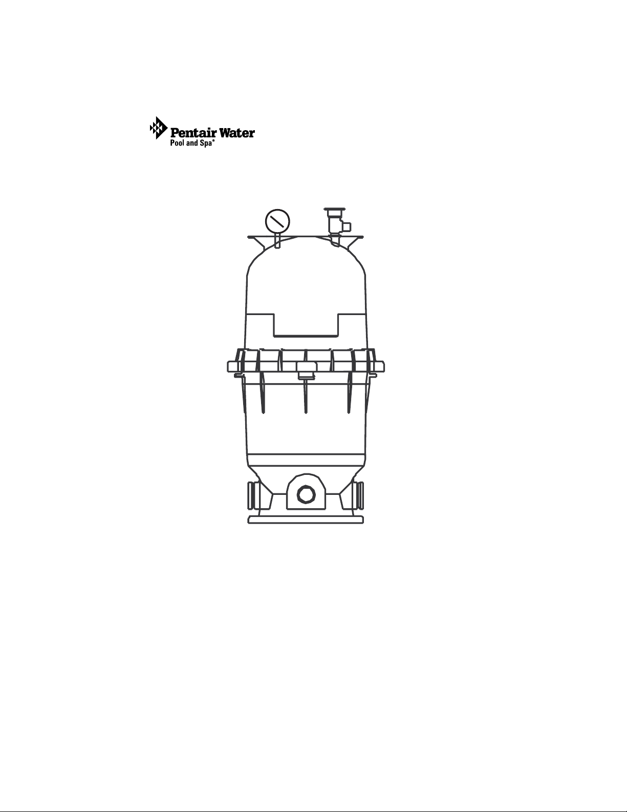
Your high rate Diatomaceous Earth (DE) filter is designed to filter out
particles as small as five microns to produce clear, sparkling water. The DE
filter element life will vary with pool conditions such as bather load, wind,
dust, etc. Water enters the filter through the “inlet” port at the bottom of the
filter and is distributed evenly across the DE filter element. The dirt is
removed by the element and the clean water flows through the “outlet” port
at the bottom of the tank. The clean water is then returned to the pool
through the piping or hoses.
This filter operates under high pressure. When any part of the circulating
system (e.g., clamp, pump, filter, valves, etc.) is serviced, air can enter the
system and become pressurized. Pressurized air can cause the lid or lock
ring to separate which may result in serious injury, death, or property
damage. To avoid this potential hazard, follow these instructions.
1. Before the assembly, disassembly, or adjustment of the lid, or lock ring or
any other service of the circulating system:
(a) Turn the pump off and shut off any automatic controls to ensure the system
is not inadvertently started during the servicing;
(b) Open manual air relief valve;
(c) Wait until all pressure is relieved, pressure gauge must read zero (0).
2. Whenever installing the filter lock ring, follow the filter lid and lock ring
installation instructions exactly.
3. Once service on the circulating system is complete, follow system restart
instructions exactly.
4. Maintain circulation system properly. Replace worn or damaged parts
immediately (e.g., lock ring, pressure gauge, relief valve, o-rings, etc.).
5. Be sure that the filter is properly mounted and positioned according to
instructions provided.
1
After a period of time, dirt will accumulate in the filter element causing a
resistance to the flow of water through the filter. This resistance results in a
diminished flow of water and a rise in the pressure of the filter. Eventually
the filter element will have removed so much dirt and the filter pressure risen
to such a point that it will be necessary to clean your filter.
DE Element Filter Installation and User’s Guide
Page 6
2
The filter’s function is to remove suspended matter from the water. It does
not sanitize the water. For sparkling clear water, the water must be sanitized
as well as balanced. Pool chemistry is a specialized area, and you should
consult your local pool service specialist for specific details. In general,
proper pool sanitation requires a free chlorine level of 1 to 2 PPM and a pH
range of 7.2 to 7.6. Your filtration system should be designed to meet your
local health codes. As a minimum, you must be sure that your system will
turnover the total volume of water in your pool at least twice in a twentyfour hour period.
Failure to operate your filter system or inadequate
filtration can cause poor water clarity obstructing visibility
in your pool. Poor water clarity may obscure objects in the water which
while swimming and diving could cause serious personal injury or death.
Never swim in a pool with poor water clarity.
Section 2
Installation
1. Read and understand all instructions before attempting
to install, operate or maintain your pump and DE filter
system.
2. Provide space and lighting for routine maintenance access.
Locate the system close to the pool. Install electrical controls
(e.g., on/off switches, timers, control systems, etc.) at least
five (5) feet from the filter. This will allow you enough room
to stand clear of the filter during system start up.
3. Remove all individual components from carton and inspect for
any visible damage. If carton or parts are damaged contact
seller or freight company.
DE Element Filter Installation and User’s Guide
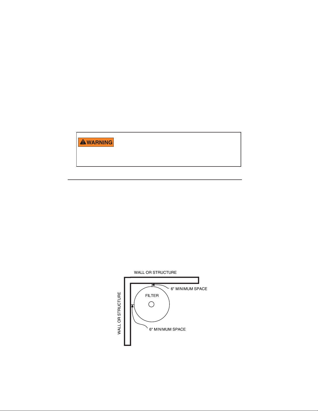
Figure 1.
Page 7

Blockage of suction fittings can cause serious or fatal
injury due to drowning. To reduce the risk of injury, do
not permit children to use this product.
Never work on the pump while it is running or power is
still connected. High voltage can cause serious or fatal
injury. A suitable ground fault interrupter (GFCI) should always be
installed at the power supply source of this unit. Be sure to ground the
motor before connecting to electrical AC power supply. Failure to
ground the motor can cause serious or fatal electrical shock hazard. DO
NOT ground to a gas supply pipe line.
4. The filter should be mounted on a level concrete slab. Position the
filter so that the instructions, warnings and pressure gauge are visible
to the operator. Also, position the filter so that the piping connections
and drain port are convenient and accessible for servicing and
winterizing.
5. Install electrical controls (e.g., on/off switches, timers control
systems, etc.) at least five (5) feet from the filter. This will allow you
enough room to stand clear of the filter during system start up.
3
6. Provide sufficient clearance around the filter to permit visual
verification that the lock ring is properly installed, see Figure 1.
7. Provide sufficient space above the filter to remove the filter lid or for
cleaning and servicing. This distance will vary with the model of filter
you are using. See Table 1 below for the required vertical clearance.
Risk of electrical shock or electrocution. Position the
filter and High Flow™ manual air relief valve to safely
direct water drainage and purged air or water. Water
discharged from an improperly positioned filter or
valve can create an electrical hazard that can cause
severe personal injury as well as damage property.
Table 1.
Model Size Required vertical clearance
ECDE60 15 sq. ft 36 in
ECDE90 30 Sq. ft 68 in
DE Element Filter Installation and User’s Guide
Page 8

4
8. When installing the High Flow™ manual air relief valve use the
O-ring only, there is no need for thread sealing compounds. Position
the filter to safely direct water drainage. Rotate the High Flow™
manual air relief valve to safely direct purged air or water. Water
discharged from an improperly positioned filter or valve can create
an electrical hazard as well as damage property.
9. Make all plumbing connections in accordance with local plumbing
and building codes. Filter plumbing connections are provided with an
O-ring seal. Use only a silicone base lubricant on the O-rings. Do
not use pipe joint compound, glue or solvent on the bulkhead
connections.
10. The base of this filter is provided with two (2) mounting bosses for
the purpose of anchoring the filter to the concrete.
11. The maximum working pressure of this filter is 50 psi. Never subject
this filter to pressure in excess of this amount, even when
conducting hydrostatic pressure tests. Pressures above 50 psi can
cause the lid to separate, which can result in severe injury, death or
property damage.
When performing hydrostatic pressure tests or when testing for
external leaks of the completed filtration and plumbing system,
insure that the Maximum Pressure that the filtration system will
be subjected to DOES NOT EXCEED THE MAXIMUM
WORKING PRESSURE OF ANY OF THE COMPONENTS
CONTAINED WITHIN THE SYSTEM. In most cases, the
maximum pressure will be stated on each component of the
system.
High Pressure:
Improper tank lid and lock
ring assembly could cause
the lid to separate and cause
serious injury and/or major
property damage.
If doubt exists as to the pressure to which the system will be
subjected, install an ASME approved automatic Pressure Relief
or Pressure Regulator in the circulation system for the lowest
working pressure of any of the components in the system.
DE Element Filter Installation and User’s Guide
Page 9

12. Use sealant on all tapered male connections of pipes and fittings.
Use only sealant compounds suited for plastic pipe. Support pipe
to prevent strains on filter, pump or valve. DO NOT USE
PETROLEUM BASED PRODUCTS.
13. Install pressure gauge in 1/4” NPT port located in the tank lid.
14. Never store pool chemicals within ten (10) feet of your pool filter
or pump. Pool chemicals should always be stored in a cool, dry,
well ventilated area.
Chemical fumes and/or spills can cause serious
corrosion to the filter and pump structural components. Structurally
weakened components can cause filter, pump or valve attachments to
separate and could cause serious bodily injury or property damage.
The system’s centrifugal pump operates with electrical
voltage, and can generate both vacuum and pressure in the water
system. When properly wired and plumbed, this pump will operate in a
safe manner.
High voltage can cause serious or fatal injury. Always
install a suitable GFCI at the power source of this unit as an added
safety precaution. Article 681-31 of the NEC requires that a GFCI be
used if this pump is used with a storable pool.
5
15. Avoid over tightening the pipe threads when connecting fittings to
the pump or filter. Proper procedure is to apply a pipe sealant to
the thread and then install hand tight plus one turn. DO NOT
OVER TIGHTEN.
DE Element Filter Installation and User’s Guide
Page 10

6
Section 3
Operation and Maintenance
Initial Start-Up
1. This filter operates under pressure. When the lock ring is installed
properly and operated without air in the water system, this filter
will operate in a safe manner.
2. The maximum working pressure of this filter is 50 psi. Never
subject this filter to pressure in excess of this amount - even when
conducting hydrostatic pressure tests. Pressures above 50 psi can
cause the lid to separate, which can result in severe injury, death or
property damage. When performing hydrostatic pressure tests or
when testing for external leaks of the completed filtration and
plumbing system, insure that the Maximum Pressure that the
filtration system will be subjected to DOES NOT EXCEED THE
MAXIMUM WORKING PRESSURE OF ANY OF THE
COMPONENTS CONTAINED WITHIN THE SYSTEM. In
most cases, the maximum pressure will be stated on each
component of the system. If you are not sure what the system
pressure will be, install an ASME approved automatic Pressure
Relief or Pressure Regulator in the circulation system for the
lowest working pressure of any of the components in the system.
This filter operates under pressure. With the lock ring and lid
installed properly and operated without air in the system, this
filter will operate in a safe manner. Air entering the filter and
the lock ring or lid not installed correctly can cause the lid to
separate, which could cause serious personal injury and/or
property damage.
DO NOT attempt to disassemble or adjust the filter unless
you fully understand it's operation. Serious injury or death can
occur if the equipment is improperly handled. Consult a pool
service professional for maintenance and service assistance.
1. Be sure all connections have been made and are secure.
2. Make sure the hair and lint pot of the pump is filled with water.
FAILURE TO FILL THE HAIR AND LINT POT WITH WATER
WILL RESULT IN DAMAGE TO THE PUMP AND PUMP SEAL.
3. OPEN THE HIGH FLOW MANUAL AIR RELIEF VALVE UNTIL
IT SNAPS INTO THE FULL OPEN POSITION. THIS ONLY
REQUIRES A ¼ TURN COUNTERCLOCKWISE.
DE Element Filter Installation and User’s Guide
Page 11

4. STAND CLEAR OF THE FILTER. Start the pump allowing the
filter tank to fill with water. Close the High Flow manual air relief
valve after a steady stream of water appears.
5. Remove the skimmer lid, put the recommended amount of
diatomaceous earth (D.E) into the skimmer. The D.E. will be drawn
into the filter and deposited evenly upon the element cartridge. Now
the filter is providing the pool with bright, clean water.
NOTE: DO NOT OPERATE FILTER WITHOUT D.E. CHARGE
FOR MORE THAN TWO MINUTES. DO NOT USE MORE
THAN THE RECOMMENDED AMOUNT OF D.E. IN YOUR
FILTER.
REGENERATIVE D.E. RECOMMEDATION
The amount of D.E. should be between one (1) and two (2) pounds for
each 10 square feet of filter area or:
MODEL Pounds of D.E.
ECDE60 1.5
ECDE90 3.0
6. Your filter has now started its filter cycle. You should check that the
water is returning to the pool and take note of the operating pressure.
7. Check the system for water leaks. If a leak is found, shut off pump
before correcting leak.
8. The pressure gauge is the primary indicator of how the filter is
operating. Maintain your pressure gauge in good working order.
9. Clean your filter when pressure reads between 8-10 psi higher than
the original starting pressure. Your filter pressure reading will increase
as it removes dirt from your pool. However, this buildup of pressure
will vary due to different bathing loads, temperature, weather
conditions, etc.
7
a. MY ORIGINAL STARTING PRESSURE IS ___________
psi (pounds per square inch). I SHOULD CLEAN THE
FILTER DE ELEMENT AT __________ psi.
DE Element Filter Installation and User’s Guide
Page 12

8
LOCK RING INSTALLATION
These instructions MUST BE FOLLOWED EXACTLY to prevent the lid
from separating during system restart or later operation.
1. Perform the following steps before working on any part of the
circulating system (e.g., lock ring, pump, filter, valves, etc.).
a. Turn the pump off and shut off any automatic controls to ensure
that the system is not inadvertently started during servicing.
b. Open the air relief valve.
c. Wait until all pressure is relieved. Never attempt to as-
semble, disassemble or adjust the filter lock ring while
there is any pressure in the filter.
2. Be certain the O-ring is in position in the lower tank half. Place the
filter lid over the lower tank half. Making sure it is fully and firmly
seated on the tank half, see Figure 2 on page 8.
This filter operates under pressure. With the lock ring
and lid installed properly and operated without air in
the system, this filter will operate in a safe manner. Air
entering the filter and the lock ring or lid not installed
correctly can cause the lid to separate, which could
cause serious personal injury and/or property damage.
THIS FILTER OPERATES UNDER HIGH PRESSURE. WHEN
ANY PART OF THE CIRCULATING SYSTEM (e.g., LOCK
RING, PUMP, FILTER, VALVES, ETC.) IS SERVICED, AIR
CAN ENTER THE SYSTEM AND BECOME PRESSURIZED.
PRESSURIZED AIR CAN CAUSE THE LID TO SEPARATE
WHICH CAN RESULT IN SEVERE INJURY, DEATH, OR PROPERTY
DAMAGE. TO AVOID THIS POTENTIAL HAZARD, FOLLOW THESE
INSTRUCTIONS.
3. Place lock ring over tank lid, and
centering the lock ring on the
threads of the tank body, turn the
lock ring clockwise until the safety
latches click and the lock ring hits
the stops on the body. DO NOT
ATTEMPT TO OVER-TIGHTEN
THE LOCK RING AFTER
LOCK RING HAS HIT THE
STOPS ON THE BODY.
4. Proceed to “Filter Restart” on
page 9.
DE Element Filter Installation and User’s Guide
Filter Tank
Top
Lock Ring
Filter
Tank
Body
Figure 2.
Page 13

FILTER RESTART
THIS FILTER OPERATES UNDER HIGH
PRESSURE. WHEN ANY PART OF THE
CIRCULATING SYSTEM (e.g., LOCK RING, PUMP,
FILTER, VALVES, ETC.) IS SERVICED, AIR CAN
ENTER THE SYSTEM AND BECOME
PRESSURIZED. PRESSURIZED AIR CAN CAUSE
THE LID TO SEPARATE WHICH CAN RESULT IN
SEVERE INJURY, DEATH, OR PROPERTY
DAMAGE. TO AVOID THIS POTENTIAL HAZARD,
FOLLOW THESE INSTRUCTIONS.
1. Open the High Flow™ manual air relief valve until it snaps
into the full open position (this only requires a quarter turn
counterclockwise). Opening this valve rapidly releases air trapped
in the filter.
2. Stand clear of the filter tank, then start the pump.
3. Close the High Flow
of water appears.
4. The system is not working properly if either of the following
conditions occur.
a. A solid stream of water does not appear within 30 seconds,
after the pump's inlet basket fills with water.
b. The pressure gauge indicates pressure before water outflow
appears.
™
manual air relief valve after a steady stream
9
If either condition exists, shut off the pump immediately,
open valves in the water return line to relieve pressure, and
clean the air relief valve, see “Cleaning the High Flow
™
Manual
Air Relief Valve” on page 11. If the problem persists, call
Technical Support (1-800-831-7133) for assistance.
The following information should be read carefully
since it outlines the proper manner of care and
operation for your filter system. As a result of
following these instructions and taking the
necessary preventative care, you can expect
maximum efficiency and life from your filtration
system.
DE Element Filter Installation and User’s Guide
Page 14

10
Please heed all manufacturers' posted instructions,
warnings and cautions when using Baquacil® or
Baqua Clean®.
CLEANING THE FILTER
1. Turn the pump off, shut off any automatic controls to ensure that the
system is not inadvertently started during servicing.
2. Open the filter High Flow™ manual air relief valve, (and the waste drain
valve, or cap, if your system has one).
NOTE: Special care must be taken when cleaning the filter element used in
®
a swimming pool or spa using Baquacil
Baquacil works, the filter media must be cleaned more thoroughly and
more frequently than in a chlorine system, If extreme care is not taken to
completely remove all residue from the filter element a buildup will occur.
This buildup will significantly shorten the life of the filter element.
Baquacil is a mild coagulant which combines bacterial cells as well as
other small particles contributed by the environment, bathers, etc. into
particles large enough to be trapped by the filter. In comparison with all
other trapped contaminants in a typical pool or spa the amount of bacterial
cells that are deposited on the filter is minimal. The resulting deposit is a
gray sticky film which can only be removed with Baqua® Clean. If TSP or
any TSP type cleaner is used prior to stripping the film, the cleaner and the
gray film will combine to form a gum-like substance. Once this occurs, the
substance cannot be removed from the media and the filter media must be
replaced.
as a sanitizer. Because of the way
3. Remove hair and lint strainer pot lid and clean basket. Replace basket
and secure lid.
4. Disconnect air relief drain hose if installed.
5. Remove locking ring by depressing safety latches on both sides of
ring and rotate counterclockwise, then remove tank lid.
6. Remove the DE Cartridge style element assembly by placing hands in
lifting handles and pulling straight up on the element assembly.
7. Using a garden hose with a nozzle, direct water spray at the element
to dislodge and wash away accumulated foreign matter.
8. Clean and remove debris from inside the filter tank and from O-ring and
O-ring groove on tank body.
9. Replace the clean element assembly into the filter tank body, making
sure it is fully seated. Align the arrow on the handle frame with inlet
port of filter.
DE Element Filter Installation and User’s Guide
Page 15

10. Replace the tank lid onto the tank body making sure it is fully and
firmly seated on the tank body.
11. Place lock ring over tank lid, and centering the lock ring on the
threads of the tank body, turn the lock ring clockwise until the safety
latches click and the lock ring hits the stops on the body. DO NOT
ATTEMPT TO OVER-TIGHTENED THE LOCK RING AFTER
LOCK RING HAS HIT THE STOPS ON THE BODY.
Any time the filter tank is opened, and/or element assembly is removed,
be sure to generously coat the O-ring with silicone lubricant before
reassembling the unit. DO NOT USE PETROLEUM BASED
LUBRICANTS BECAUSE THEY HAVE A DETERIORATING EFFECT ON
RUBBER.
12. Replace drain cap and reinstall air relief valve drain hose if used.
REPLACING FILTER ELEMENT
Element life will vary with pool conditions such as bather load,
wind, dust, etc. You can expect an average media life of three
years under normal conditions.
11
1. To replace the element, follow “Cleaning The Filter” instructions on
page 10.
CLEANING THE HIGH FLOW MANUAL™ AIR RELIEF
VALVE
1. Turn the pump off and shut off any automatic controls to ensure that
the system is not inadvertently started during servicing.
2. OPEN THE HIGH FLOW
VALVE UNTIL IT SNAPS INTO THE FULL OPEN
POSITION, THEN WAIT UNTIL ALL PRESSURE IS
RELIEVED.
3. With the relief valve attached to the filter tank, pull out the locking
tabs and remove the valve stem and cover assembly with a
counterclockwise and lifting motion, see Figure 3 on page 12.
™
MANUAL AIR RELIEF
DE Element Filter Installation and User’s Guide
Page 16

12
4. Clean debris from the valve stem and body. Verify that the filter
tank's air passage is open by inserting a 5/16" drill bit through the
valve body. Verify that the O-rings are in good condition, properly
positioned, and lubricated with a silicone base lubricant.
5. Reinstall the valve stem and cover assembly with a downward and
clockwise motion until it snaps into position.
Figure 3.
Figure 3.
DE Element Filter Installation and User’s Guide
Page 17
Winterizing the System
Allowing water to freeze in the system will damage
the system and cause potential water damage/
flooding and potential property damage.
1. In areas that have freezing winter temperatures, the pool
equipment must be winterized to protect it from damage.
2. Open the High Flow
3. Remove the drain port cap at the bottom of the filter.
IMPORTANT NOTE: Remove drain port cap for
draining water from filter. Leave the drain port cap off
and store it during the time the system is shut down.
4. Drain all appropriate system piping.
5. It is recommended that the pump and filter be covered with a
tarpaulin or plastic sheet to inhibit deterioration from the
weather. DO NOT wrap the pump motor with plastic.
6. In installations where the pump cannot be drained a 40%
Propylene Glycol 60% water solution will protect to -50° F
(-45.5° C)
™
manual relief valve.
13
Note: Do not use anti-freeze solutions except Propylene
Glycol; as other anti-freeze are highly toxic and will
damage the pump.
Technical Data and Replacement Parts
Note
Please see the provided insert sheet for
Technical Data and Replacement Parts information specific to your
Filter.
DE Element Filter Installation and User’s Guide
Page 18

14
Section 4
Troubleshooting
A. Air entering your filter is dangerous and can cause the lid to separate.
Correct any conditions in your filtration system that allows air to enter
the system.
1. Some common ways to identify air entering the system:
a. Low water level in pool or spa - skimmer is starving for water
with pump running. Add water to pool or spa.
b. Air bubbles or low water level in pump hair and lint pot are
caused by; low water level, clogged skimmer basket, split
suction cleaner hose, leak in pump hair and lint pot lid, or leak in
pump suction line.
c. Air bubbles coming out of water return lines into pool or spa
with pump running, see items 1.a and 1.b of this section.
d. Air is discharged from the air relief valve on top of the filter
when the valve is opened with the pump running, see items 1.a
and 1.b of this section, above.
B. Until the water initially put into the pool has been completely filtered,
short filter cycles in between cleanings are normal. In most cases pool
owners are dismayed by the undesirable color and appearance of water
in a newly filled pool. Plaster dust can be responsible for short filter
cycles, requiring frequent cleaning.
C. If pressure drops on gauge, check skimmer basket and pump basket first
for debris. If the baskets are clean, shut off power to pump and turn off
any automatic controls. Then turn motor shaft with your fingers. If it
turns freely then the pump must be disassembled and the impeller
checked to see if it is clogged. If it is not frozen or clogged then there is
an obstruction in the line between the pool and the pump.
D. The pressure gauge is an important part of the filter system. It is your
primary indicator of how the system is operating. Maintain your pressure
gauge in good working order. Check the operation of your pressure
gauge in the following manner:
1. The pressure gauge should go to zero (0) when the system is turned
off and pressure is relieved.
2. The pressure gauge should indicate pressure when the system is
operating.
3. The pressure gauge should be readable and not damaged in any
way.
4. Replace the pressure gauge if it is not meeting the requirements of
items D.1 through D.3 of this section, above.
DE Element Filter Installation and User’s Guide
Page 19

looprorelaedtlusnocroemitre
retlifnaelcevobaisp01otdliuboterusserpwollA
ecivrestlusnocroyrtsimehcloopniatniaM
.enilnruterninoitcurtsboevomerroevlavnepO
ecivreslooptlusnocroyrtsimehcloopniatniaM
.senilninoitcurts
.tnemelegninaelcerofebnoitidnoc
.naicinhcet
.elcycgn
tibihniotetauqedatonyrtsimehclooP.1
inaelctnemelenatneuqerfooT.2
.etarrevonrutetauqedanI.3
.htworgeagla
.devomersisirbedllalitnunaelC
gnolrofmetsysnuR
.naicinhcetecivres
.devomersisirbedllalitnunaelC
tibahniotetauqedatonyrtsimehclooP.2
.noitcirtserroevla
vdesolcyllaitraP.2
.retliffoyticapacotwolftcir
.reniartsniteksabnaelC
.naicinhcet
tseR
.toptnildnariahpmupehtninoitcurtsbO.1
.hgihootetarwolF.3
.htworgeagla
boevomeR.teksabremmiksnaelC
.pmupnaelcdnaelbmessasiD
.enilnoitcusnisevlavnepO
.pmupotenilnoitcusninoitcurtsbO.3
.pmupninoitcurt
sbO.2
.erusserpretlifrehgiHgninaelctnemeletneiciffusnI.1
melborPesuaCnoitcA
.naelcyltneiciffus
tonretawlooP
.selcycretlif
trohSgninaelctnemelereporpmI.1
retlifwol,dehsinimid
loopotwolfnruteR
.erusserp
DE Element Filter Installation and User’s Guide
Page 20

*196042*
P/N 196042 Rev A
DE Element Filter Installation and User’s Guide
 Loading...