


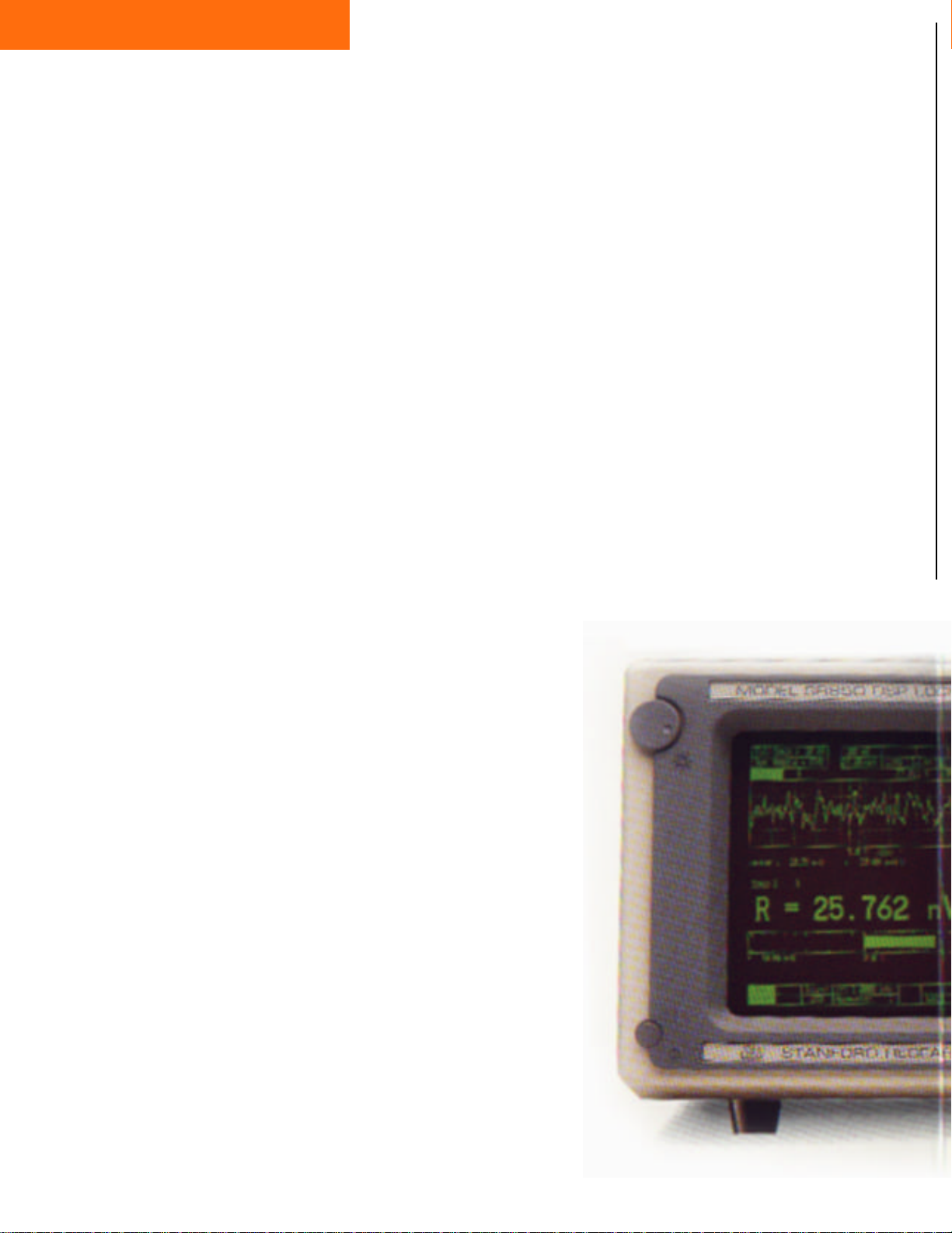
SR850
DSP Lock-In Amplifier
SR850 DSP
ntroducing the SR850 DSP
I
Lock-In Amplifier from Stanford Research Systems - The
next generation of lock-in amplifiers.
Lock-In Amplifier
$7500 (U.S. list price)
• 100 dB dynamic reserve without
prefiltering (5ppm stability)
• 1 mHz to 102 kHz bandwidth
• 0.001° phase resolution
• Time constants from 10 µs to 30 ks
Digital Signal Processing
The SR850 is a dual phase
lock-in amplifier that uses digital signal processing (DSP) to
replace the demodulator, lowpass filters and DC gain amplifiers found in conventional
lock-ins. With state-of-the-art
DSP chips and a high precision
18 bit A/D converter, the
SR850 offers performance
never before available to
lock-in users - such as 0.001
degree phase resolution and
100 dB dynamic reserve.
The heart of any lock-in, the
demodulator, determines how
(6, 12, 18, 24 dB/oct rolloff)
• Synthesized reference oscillator
• 64,000 point data display
• Data analysis including curve fitting,
smoothing and statistics
• Direct plotting and printing
• 3.5 inch MS-DOS compatible disk
drive
• GPIB, RS-232, and printer interfaces

much interference or noise can
be tolerated by the instrument.
Analog lock-ins must use input
filters to achieve noise rejection
greater than 60 dB and suffer
the consequences - poor stability, output drift and excessive
gain and phase error. Demodulation in the SR850 is achieved
by digitizing the input signal,
calculating a reference sine
wave to 24 bits of accuracy,
then performing an exact digital multiplication of the two
signals. The result - the SR850
can easily reject interfering signals that are 1 million times
(120 dB) larger than the signal
being measured without using
prefilters. And there is no gain
error, output drift or stability
penalty for using ultra-high dynamic reserve.
The digital signal processor
also handles the task of output
filtering. A choice of 6, 12, 18
or 24 dB/oct rolloff is provided
for time constants ranging from
10 µs to 30 ks. When locked to
frequencies below 200 Hz, synchronous filters are used to
notch out multiples of the reference frequency. Even the F and
2F components are completely
eliminated, meaning a much
shorter output time constant can
be used in low frequency measurements.
CRT Display
In addition to these performance advantages, the SR850
has some features new to
lock-in amplifiers, such as a
CRT display. Experimental
data can now be viewed as it
occurs. The screen can be formatted as a single or dual trace
display. Bar graphs with numerical read-out, polar plots
and strip chart displays enhance
data interpretation.
The Bar graph and numerical
read-out (fig. 1) resembles a
conventional lock-in display.
The graph indicates the percentage of full scale deflection and
is useful in identifying fluctuations in the output. The large
numeric read-outs can easily be
seen from across the room.
Polar plots (fig. 2) display the
signal as a vector, providing a
convenient way to view magnitude and phase. One of the
most useful features of the
SR850 is the chart display
(fig. 3) which allows on-screen
graphing of data in strip chart
form. A time history of up to
64,000 data points can be recorded at rates up to 512 Hz,

eliminating the need for external chart recorders. Up to four
chart traces can be independently configured as (AxB)/C or
2
(AxB)/C
where A, B and C are
selected from X, Y, R, ø,
X noise, Y noise, R noise, frequency or the auxiliary A/D
inputs. While data is being acquired, marks can be added to
the charts to identify external
events, such as a change in experimental conditions. Panning
and zooming features allow
close examination of any section of the data.
On-screen Analysis
The analysis capabilities of the
SR850 seem limitless. Detection of any harmonic (2F to nF)
up to 102 kHz is now possible.
Auto measurement functions
quickly optimize the gain,
phase, dynamic reserve and
time constant parameters during
data acquisition. Once data
have been taken, powerful reduction routines including
curve smoothing, curve fitting,
statistics and math allow complex analysis without the aid of
a computer.
Synthesized Reference
Source
The internal oscillator uses
direct digital synthesis (DDS)
to provide a very low distortion
(-80 dB) reference source. It is
essentially a function generator
with sine and TTL sync outputs
capable of performing both
linear and log sweeps over the
entire 1 mHz to 102 kHz frequency range. When an external reference source is used, the
internal oscillator phase locks
to the source, and the sine and
TTL outputs can be used to
synchronize other equipment.
Inputs and Outputs
The voltage input (single-ended
or differential) has a wide sensitivity range that extends from
2 nV to 1 V. A current input is
also provided with a choice of
6
or 108 volts/amp gain
10
ratios. Both X and Y components are updated by the DSP at
256 ksamples/sec and have dedicated analog outputs. Four
auxiliary inputs (16 bit ADCs)
are provided for general purpose use, such as normalizing
signal to source intensity fluctuations or monitoring temperature. Four programmable
outputs (16 bit DACs) are also
provided and can have fixed or
swept amplitudes. Two user
defined outputs are easily configured as X, Y, R, ø, or chart
traces 1 - 4.
Communication
Standard RS-232 and GPIB
(IEEE-488) interfaces allow
quick and easy communication
with computers. The 3.5 inch
MS-DOS compatible disk drive
can store data traces and instrument setup files, or be used to
transfer data to a PC for further
analysis. Hardcopy outputs are
available with dot matrix and
LaserJet printers or HP-GL
plotters.
Easy to Use Menus
And operating the SR850 is
straightforward. All functions
are menu driven. Soft keys are
used to select options within a
menu, and the spin knob and
alpha-numeric keypad make parameter entry fast and simple.
On-screen help provides a
quick explanation for all functions of the instrument.
The SR850 DSP Lock-In Amplifier from Stanford Research
Systems. A significant step forward in the development of
lock-in amplifiers. For further
information call us at
(408)744-9040.
Figure 1 - Bar graph and numerical read-out resembles a conventional
lock-in
display.
Figure 2 - Polar plots illustrate the
signal as a vector relative to the reference signal.
Figure 3 - Chart display allows onscreen data recording (64k points).

Specifications
Specifications
SIGNAL CHANNEL
Voltage inputs
Sensitivity
Current input
Impedance
Gain accuracy
Noise
Line filters
CMRR
Dynamic reserve
REFERENCE CHANNEL
Frequency range
Reference input
Input impedance
Phase resolution
Absolute phase error
Relative phase error
Orthogonality
Phase noise
Phase drift
Harmonic detection
Acquisition time
DEMODULATOR
Stability
Harmonic rejection
Offset / Expand
Time constants
Single-ended or differential
2 nV to 1 V
106 or 108 Volts/Amp
Voltage: 100 MΩ + 25 pf, AC or DC
coupled
Current: 1 kΩ to virtual ground
± 0.5 % (20-30°C)
4 nV/√Hz at 1 kHz
0.13 pA/√Hz at 1 kHz
60 [50] Hz and 120 [100] Hz notch
(Q=5 )
90 dB at 1 kHz
0 to 100 dB (without prefilters)
0.001 Hz to 102 kHz
TTL or sine (200 mV
1 MΩ, 25 pf
0.001°
< 1°
< 0.001° on X and Y outputs
90° ± 0.001°
Internal oscillator reference: Synthesized, no phase noise.
External reference applied:
0.005° rms
12 dB/oct.
< 0.01°/°C below 10 kHz,
< 0.1°/°C below 100 kHz.
2F, 3F, ... nF to 102 kHz.
2 cycles + 2 ms or 20 ms (whichever
is larger)
Digital outputs and display: no drift.
Analog outputs: < 5 ppm/°C for all
dynamic reserve settings.
-100 dB
± 100% offset. Expand up to 256x.
10 µs to 30 ks (6, 12, 18, 24 dB/oct
rolloff). Synchronous filters available below 200 Hz.
at 1 kHz, 100 ms,
p-p
minimum)
X, Y outputs
CH1 output
CH2 output
Aux. A/D inputs
Aux. D/A outputs
Sine Out
TTL Out
Trigger In
Remote pre-amp
DISPLAYS
Screen format
Displayed quantities
Display types
Data buffer
ANALYSIS FUNCTIONS
Sine and cosine components (±
10V). Updated at 256 ksamples/
sec.
± 10V output of
(each trace defined as AxB/C or
AxB/C2 where A, B, C are selected
from X, Y, R, ø, X noise, Y noise,
R noise,
± 10V output of Y, ø or Trace 1- 4
(each trace defined as AxB/C or
AxB/C2 where A, B, C are selected
from X, Y, R, ø, X noise, Y noise,
R noise, Aux 1-4 or frequency).
4 BNC inputs, 16 bit, ± 10 V.
4 BNC outputs, 16 bit, ± 10 V,
(fixed or swept amplitude).
Internal oscillator analog output.
Internal oscillator TTL output.
TTL signal either starts internal oscillator sweeps or synchronizes instrument data taking (rates to
512 Hz).
Provides power and gain control
signals to the optional SR550 and
SR552 preamplifiers.
Single or dual display.
Each display shows one trace.
Traces are defined as AxB/C or
AxB/C2 where A, B, C are selected
from X, Y, R, ø, X noise, Y noise,
R noise, Aux 1 - 4 or frequency.
Large numeric readout with bar
graph, polar plot or strip chart.
64k data points can be stored and
displayed as strip charts. The
buffer can be configured as a single
trace with 64k points, 2 traces with
32k points each, or 4 traces with up
to 16k points each.
X, R or Trace 1- 4
Aux 1-4
or frequency).
INTERNAL OSCILLATOR
Range
Stability
Resolution
Distortion
Amplitude
Amplitude accuracy
Amplitude stability
Outputs
Sweeps
INPUTS AND OUTPUTS
Interfaces
1 mHz to 102 kHz
25 ppm from 0°C to 70°C.
0.01% or 0.001 Hz, whichever is
greater.
- 80 dB
0.004 to 5 Vrms into 10 kΩ (3 digit
resolution)
1%
50 ppm/°C
Sine, TTL. (When using an external
reference, both outputs are phase
locked to the external reference)
Linear and Log
IEEE-488, RS-232
printer interfaces standard. All instrument functions can be controlled
and read through
RS-232
interfaces.
and Centronics
IEEE-488
and
Smoothing
Curve fitting
.
Calculator
Statistics
GENERAL
Hardcopy
Disk drive
Power
Dimensions
Weight
Warranty
5, 9, 17, 21 or 25 point
Savitsky-Golay
Linear, exponential or Gaussian
Arithmetic, trigonometric and logarithmic calculations on trace
region.
Mean and standard deviation of
trace region.
Screen dumps to dot matrix or
LaserJet
compatible plotters (
GPIB).
3.5 inch
format, 720 kbyte capacity. Storage of data and instrument setups
(binary or ASCII).
60 Watts, 100/120/220/240 VAC,
50/60 Hz.
17"W x 6.25"H x 16.5"L
40 lbs.
One year parts and labor.
smoothing.
printers. Plots to
MS-DOS
RS-232
compatible
HP-GL
or
A bit about DSP
Digital signal processing (DSP) is commonly used to replace specialized analog circuits in a system with specific
mathematical computations. In a lock-in amplifier, DSP can be used to eliminate the demodulator, output filters and
DC gain circuits, and enhance the performance of the instrument.
All conventional lock-ins suffer from problems in the demodulator where an analog input signal is mixed with an
analog reference signal. If you can digitize the input signal and calculate a reference sine wave to a high enough
degree of accuracy, you can demodulate the two signals by performing a digital multiply. In principle, you cannot do
better than multiplying a digitized number by a calculated number. There are no mistakes, no drifts, and no errors.
The SR850 uses a precision 18 bit ADC to convert the input signal to a digital bit stream. The DSP, which is locked to
the reference signal, calculates a pure sine reference for the multiply. Because the calculated sine reference signal is
generated with 24 bits of accuracy, the phase resolution and orthogonality are 0.001°, or 1000 times better than a conventional lock-in.
The DSP performs sixteen million 24-bit multiplies and adds each second and produces an answer accurate to 48 bits.
This results in 100 dB of real dynamic reserve (no prefiltering) free of the gain errors, output drift and noise penalties
common to analog lock-ins. The SR850 maintains 5 ppm/°C stability even at a dynamic reserve of 100 dB. In contrast, analog lock-ins have about 20 dB of dynamic reserve at 5 ppm/°C stability.
Finally, the replacement of the output filter circuits by a pure mathematical calculation allows additional flexibility and
improved performance. The filter rolloff is now simply a function of the filtering algorithm, and 6, 12, 18 and 24 dB/
oct can all be offered. Furthermore, time constants can be varied from 10 µsec to 30,000 seconds with no associated
error or costly circuitry. With the aid of DSP technology, the SR850 has become the most effective lock-in amplifier
available for extracting a small signal from a noisy background.
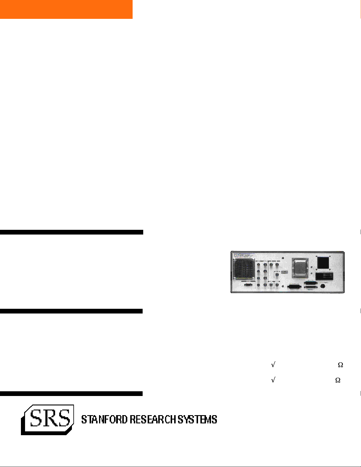
Rear Panel
The rear panel of the SR850 includes standard IEEE-488 (GPIB) and
RS-232 computer interfaces, printer port, keyboard connector (IBM
compatible) for text and numeric entry, remote preamplifier control
input, four ADC inputs, four DAC outputs, trigger input, oscillator
output, signal monitor output, and X and Y outputs.
Ordering Information (all prices U.S. list)
SR850 OPTIONS
DSP Lock-In Amplifier $7500 SR540 Chopper $995 4 Hz to 4 kHz, 4 digit display,
input control voltage.
SR550 Preamplifier $495 2.8 nV/ Hz input noise, 100 M
input impedance.
SR552 Preamplifier $495 1.4 nV/ Hz input noise, 100 k
input impedance.
1290 D Reamwood Avenue • Sunnyvale, CA 94089
Telephone (408)744-9040 • FAX: 4087449049
www.thinkSRS.com • e-mail: info@thinkSRS.com
Printed in USA ©1992 Stanford Research Systems, Inc. All specifications and prices subject to change (4/92)
 Loading...