


30 MHz Synthesized
Function and Arbitrary
Waveform Generator
model DS345
1290 D Reamwood Avenue
Sunnyvale, CA 94089 USA
Phone: (408) 744-9040 • Fax: (408) 744-9049 www.thinkSRS.com • e-mail: info@thinkSRS.com
Copyright© 1999
All Rights Reserved
Revision 1.6 • 10/99
Stanford Research Systems

DS345 SYNTHESIZED FUNCTION GENERATOR
Table of Contents
Condensed Information
Safety and Use |
v |
Specifications |
vii |
Abridged Command List |
xi |
Getting Started
Introduction |
1-1 |
CW Function Generation |
1-1 |
Frequency Sweep |
1-2 |
Tone Bursts |
1-3 |
Operation
Introduction to DDS |
2-1 |
DS345 Features |
2-5 |
Front Panel Features |
2-5 |
Rear Panel Features |
2-7 |
Function Setting |
2-9 |
Setting the Function |
2-10 |
Frequency |
2-10 |
Amplitude |
2-11 |
DC Offset |
2-12 |
Phase |
2-12 |
Sweeps and Modulation |
2-13 |
Modulation Parameters |
2-13 |
Modulation On/Off |
2-13 |
Modulation Type |
2-13 |
Modulation Rate |
2-14 |
Amplitude Modulation |
2-15 |
External AM |
2-15 |
Internal AM |
2-15 |
Frequency Modulation |
2-16 |
Phase Modulation |
2-17 |
Burst Modulation |
2-18 |
Burst Count |
2-18 |
Starting Point |
2-18 |
Frequency Sweeps |
2-19 |
Sweep Type |
2-19 |
Sweep Frequencies |
2-19 |
Sweep Markers |
2-20 |
Sweep Outputs |
2-21 |
Trigger Generator |
2-22 |
Arbitrary Modulation Patterns |
2-23 |
Pulse Generation |
2-24 |
Instrument Setup |
2-25 |
Default Settings |
2-25 |
Store and Recall |
2-25 |
GPIB and RS232 Setup |
2-26 |
Self-Test and Autocal |
2-27 |
Arbitrary Waveform Editing |
2-29 |
Edit Menu |
2-29 |
Point Format Editing |
2-30 |
Point Format Example |
2-31 |
Vector Format Editing |
2-32 |
Vector Format Example |
2-33 |
Programming
Programming the DS345 |
3-1 |
Communications |
3-1 |
GPIB Communication |
3-1 |
RS-232 Communication |
3-1 |
Data Window |
3-1 |
Command Syntax |
3-1 |
Detailed Command List |
3-3 |
Function Output Commands |
3-3 |
Modulation Control |
3-4 |
Arb Waveform and Modulation |
3-6 |
Setup Control Commands |
3-9 |
Status Reporting Commands |
3-9 |
Test and Calibration Commands 3-10 |
|
Status Byte Definitions |
3-12 |
Programming Examples |
3-15 |
Arbitrary AM Modulation |
3-16 |
Arbitrary FM Modulation |
3-17 |
Arbitrary PM Modulation |
3-18 |
Point Mode Arb Waveform |
3-19 |
Vector Mode Arb Waveform |
3-20 |
Test and Calibration |
|
Troubleshooting |
4-1 |
Operation Error Messages |
4-1 |
Self-Test Error Messages |
4-3 |
Autocal Error Messages |
4-4 |
i


 DS345 SYNTHESIZED FUNCTION GENERATOR
Performance Tests |
5-1 |
Necessary Equipment |
5-1 |
Functional Tests |
5-2 |
Front Panel Test |
5-2 |
Self Tests |
5-2 |
Sine Wave |
5-2 |
Square Wave |
5-2 |
Amplitude Flatness |
5-3 |
Output Level |
5-3 |
Performance Tests |
5-5 |
Frequency Accuracy |
5-5 |
Amplitude Accuracy |
5-5 |
DC Offset Accuracy |
5-7 |
Subharmonics |
5-7 |
Spurious Signals |
5-8 |
Harmonic Distortion |
5-8 |
Phase Noise |
5-9 |
Square Wave Rise Time |
5-10 |
Square Wave Symmetry |
5-10 |
AM Envelope Distortion |
5-10 |
Test Scorecard |
5-11 |
Calibration |
6-1 |
Introduction |
6-1 |
Calibration Enable |
6-1 |
Calbytes |
6-1 |
Necessary Equipment |
6-3 |
Adjustments |
6-3 |
Clock Adjustment |
6-3 |
DAC Reference Voltage |
6-4 |
Output Amplifier Bandwidth |
6-4 |
Bessel Filter Adjustment |
6-4 |
Harmonic Distortion |
6-5 |
Calibration |
6-6 |
5.00 V Reference |
6-6 |
Clock Calibration |
6-6 |
Attenuator Calibration |
6-6 |
Carrier Null Calibration |
6-7 |
Sinewave Amplitude |
6-8 |
Square Wave Amplitude |
6-8 |
Square Wave Symmetry |
6-9 |
Arbitrary Waveform Software
Introduction |
7-1 |
Getting Started with AWC |
7-1 |
Hardware Requirements |
7-3 |
Menus |
7-3 |
File Menu |
7-3 |
Edit Menu |
7-3 |
Waveform Menu |
7-4 |
Send Data Menu |
7-5 |
Set DS345 Menu |
7-5 |
Trigger Menu |
7-6 |
Zoom Menu |
7-6 |
Other Menu |
7-7 |
Mouseless Operation |
7-7 |
File Format |
7-7 |
DS345 Circuitry
Circuit Description |
8-1 |
Bottom PC Board |
8-1 |
Power Supplies |
8-1 |
Microprocessor System |
8-1 |
Display and Keyboard |
8-1 |
Ribbon Cable, Trigger and Sync 8-2 |
|
GPIB and RS232 Interfaces |
8-2 |
Output Amplifier |
8-3 |
Output Attenuator |
8-3 |
Top PC Board |
8-4 |
Ribbon Cable, ADC, DACs |
8-4 |
Clocks |
8-4 |
DDS ASIC and Memory |
8-5 |
Amplitude and Sweep DACs |
8-5 |
DDS Waveform DAC |
8-6 |
DDS Output Filters and Doubler |
8-6 |
Sync and Gain Adjust |
8-6 |
Component Parts List |
9-1 |
Bottom PC Board and Front Panel |
9-1 |
Top PC Board |
9-10 |
Optional PC Board |
9-20 |
Miscellaneous Parts |
9-22 |
ii

DS345 SYNTHESIZED FUNCTION GENERATOR
Schematic Circuit Diagrams Sheet No.
Bottom PC Board |
|
Power Supplies |
1/7 |
Microprocessor System |
2/7 |
Display and Keyboard |
3/7 |
Ribbon Cable, Trigger and Sync 4/7 |
|
GPIB and RS232 Interfaces |
5/7 |
Output Amplifier |
6/7 |
Output Attenuator |
7/7 |
Top PC Board |
|
Ribbon Cable, ADC, DACs |
1/7 |
Clocks |
2/7 |
DDS ASIC and Memory |
3/7 |
Amplitude and Sweep DACs |
4/7 |
DDS Waveform DAC |
5/7 |
DDS Output Filters and Doubler |
6/7 |
Sync and Gain Adjust |
7/7 |
Front Panel |
|
Keypad |
1/2 |
LED Display |
2/2 |
Bottom PCB Component Placement
Top PCB Component Placement
iii

 DS345 SYNTHESIZED FUNCTION GENERATOR
Symbols you may find on SRS products
Symbol |
|
Description |
||||||||
|
||||||||||
|
|
|
|
|
|
|
|
|
|
|
|
|
|
|
|
|
|
|
|
|
Alternating current |
|
|
|
|
|
|
|
|
|
|
|
|
|
|
|
|
|
|
|
|
|
Caution - risk of electrical shock |
|
|
|
|
|
|
|
|
|
|
|
|
|
|
|
|
|
|
|
|
|
Frame or chassis terminal |
|
|
|
|
|
|
|
|
|
|
|
|
|
|
|
|
|
|
|
|
||
|
|
|
|
|
|
|
|
|
|
|
|
|
|
|
|
|
|
|
|
|
Caution - refer to accompanying documents |
|
|
|
|
|
|
|
|
|
|
|
|
|
|
|
|
|
|
|
|
|
Earth (ground) terminal |
|
|
|
|
|
|
|
|
|
|
|
|
|
|
|
|
|
|
|
|
|
|
|
|
|
|
|
|
|
|
|
|
|
|
|
|
|
|
|
|
|
|
|
|
|
|
|
|
|
|
|
|
|
|
Battery |
|
|
|
|
|
|
|
|
|
||
|
|
|
|
|
|
|
|
|
||
|
|
|
|
|
|
|
|
|
|
|
|
|
|
|
|
|
|
|
|
|
Fuse |
|
|
|
|
|
|
|
|
|
|
|
|
|
|
|
|
|
|
|
|
|
On (supply) |
|
|
|
|
|
|
|
|
|
|
|
|
|
|
|
|
|
|
|
|
|
|
|
|
|
|
|
|
|
|
|
|
Off (supply) |
|
|
|
|
|
|
|
|
|
|
|
|
|
|
|
|
|
|
|
|
|
|
vi

DS345 SYNTHESIZED FUNCTION GENERATOR
Safety and Preparation for Use
WARNING: Dangerous voltages, capable of causing death, are present in this instrument. Use extreme caution whenever the instrument covers are removed.
This instrument may be damaged if operated with the LINE VOLTAGE SELECTOR set for the wrong ac line voltage or if the wrong fuse is installed.
LINE VOLTAGE SELECTION
The DS345 operates from a 100V, 120V, 220V, or 240V nominal ac power source having a line frequency of 50 or 60 Hz. Before connecting the power cord to a power source, verify that the LINE VOLTAGE SELECTOR card, located in the rear panel fuse holder, is set so that the correct ac input voltage value is visible.
Conversion to other ac input voltages requires a change in the fuse holder voltage card position and fuse value. Disconnect the power cord, open the fuse holder cover door and rotate the fuse-pull lever to remove the fuse. Remove the small printed circuit board and select the operating voltage by orienting the board so that the desired voltage is visible when it is pushed firmly back into its slot. Rotate the fuse-pull lever back into its normal position and insert the correct fuse into the fuse holder.
LINE FUSE
Verify that the correct line fuse is installed before connecting the line cord. For 100V/120V, use a 1 Amp fuse and for 220V/240V, use a 1/2 Amp fuse.
LINE CORD
The DS345 has a detachable, three-wire power cord for connection to the power source and to a protective ground. The exposed metal parts of the instrument are connected to the outlet ground to protect against electrical shock. Always use an outlet which has a properly connected protective ground.
v


 DS345 SYNTHESIZED FUNCTION GENERATOR
vi
SPECIFICATIONS
FREQUENCY RANGE |
|
|
|
|
|
|
|
|
|
|
|
|
|
|
|
|
|
Waveform |
Maximum Freq |
Resolution |
|
|
|
|
|
||||||||||
Sine |
30.2 MHz |
|
|
|
1 µHz |
|
|
|
|
|
|
|
|||||
Square |
30.2 MHz |
|
|
|
1 µHz |
|
|
|
|
|
|
|
|||||
Ramp |
100 KHz |
|
|
|
1 µHz |
|
|
|
|
|
|
|
|||||
Triangle |
100 KHz |
|
|
|
1 µHz |
|
|
|
|
|
|
|
|||||
Noise |
10 MHz |
|
|
|
(Gaussian Weighting) |
|
|
||||||||||
Arbitrary |
10 MHz |
|
|
|
40 MHz sample rate |
|
|
||||||||||
OUTPUT |
|
|
|
|
|
|
|
|
|
|
|
|
|
|
|
|
|
Source Impedance |
|
50 Ω |
|
|
|
|
|
|
|
|
|
|
|
|
|||
Output may float up to ±40V (AC + DC) relative to earth ground. |
|
|
|||||||||||||||
AMPLITUDE |
|
|
|
|
|
|
|
|
|
|
|
|
|
|
|
|
|
Range |
into 50Ω load (limited such that |Vac peak| + |Vdc| |
≤ 5 V) |
|
||||||||||||||
|
|
|
|
|
|
|
|
|
|
|
|
|
|
||||
|
|
|
|
|
Vpp |
|
|
|
Vrms |
|
dBm (50Ω) |
||||||
|
Function |
|
|
|
Max. |
|
Min. |
|
|
Max. |
Min. |
|
Max. |
Min. |
|||
|
|
|
|
|
|
|
|
|
|
|
|
|
|
|
|
|
|
|
Sine |
|
|
|
10V |
|
10 mV |
|
3.54V |
3.54 mV |
|
+23.98 |
-36.02 |
||||
|
Square |
|
|
|
10V |
|
10 mV |
|
|
5V |
5 mV |
|
+26.99 |
-33.0 |
|||
|
Triangle |
|
|
|
10V |
|
10 mV |
|
2.89V |
2.89 mV |
|
+22.22 |
-37.78 |
||||
|
Ramp |
|
|
|
10V |
|
10 mV |
|
2.89V |
2.89 mV |
|
+22.22 |
-37.78 |
||||
|
Noise |
|
|
|
10V |
|
10 mV |
|
2.09V |
2.09 mV |
|
+19.41 |
-40.59 |
||||
|
Arbitrary |
|
|
|
10V |
|
10 mV |
|
|
n.a. |
n.a. |
|
n.a. |
n.a. |
|||
|
|
|
|
|
|
|
|
|
|
|
|
|
|
|
|||
Resolution |
3 digits (DC offset = 0V) |
|
|
|
|
|
|
|
|||||||||
Accuracy (with 0V DC Offset) |
|
|
|
|
|
|
|
|
|
|
|
||||||
Sine: |
1µHz |
100 kHz |
|
20 MHz |
30.2 MHz |
|
|
||||||||||
|
10Vpp |
|
|
|
|
|
|
|
|
|
|
|
|
|
|
|
|
|
|
|
|
±0.2 dB |
|
±0.2dB |
|
|
±0.3dB |
|
|
|
|
||||
|
|
|
|
|
|
|
|
|
|
|
|||||||
|
5Vpp |
|
|
|
|
|
|
|
|
|
|
|
|
|
|
|
|
|
|
|
|
±0.4dB |
|
±0.4dB |
|
|
±0.5dB |
|
|
|
|
||||
|
|
|
|
|
|
|
|
|
|
|
|||||||
|
0.01Vpp |
|
|
|
|
|
|
|
|
|
|
|
|
|
|
|
|
|
1µHz |
|
|
|
|
|
|
|
|
|
|
|
|
||||
Square: |
100 kHz |
|
20 MHz |
30.2 MHz |
|
|
|||||||||||
|
10Vpp |
|
|
|
|
|
|
|
|
|
|
|
|
|
|
|
|
|
|
|
|
±3 % |
|
|
|
±6% |
|
|
±15% |
|
|
|
|
||
|
|
|
|
|
|
|
|
|
|
|
|
||||||
|
5Vpp |
|
|
|
|
|
|
|
|
|
|
|
|
|
|
|
|
|
|
|
|
±5% |
|
|
|
±8% |
|
|
±18% |
|
|
|
|
||
|
|
|
|
|
|
|
|
|
|
|
|
||||||
|
0.01Vpp |
|
|
|
|
|
|
|
|
|
|
|
|
|
|
|
|
Triangle, Ramp, Arbitrary: |
|
|
|
±3% |
> 5Vpp |
|
|
||||||||||
|
|
|
|
|
|
|
|
|
±5% |
< 5Vpp |
|
|
|||||
vii


 Specifications

DC OFFSET |
|
Range: |
±5V (limited such that |Vac peak| + |Vdc| ≤ 5 V) |
Resolution: |
3 digits (VAC = 0) |
Accuracy: |
1.5% of setting + 0.2 mV (DC only) |
|
±0.8 mV to ±80 mV depending on AC and DC settings |
WAVEFORMS |
|
Sinewave Spectral Purity |
|
Spurious: |
< -50 dBc (non-harmonic) |
Phase Noise: |
< -55 dBc in a 30 KHz band centered on the carrier, exclusive of |
|
discrete spurious signals |
Subharmonic: |
< -50 dBc |
Harmonic Distortion: Harmonically related signals will be less than:
Level |
Frequency Range |
||
|
|
||
< -55 dBc |
DC to 100 KHz |
||
< -45 dBc |
.1 |
to 1 MHz |
|
< -35 dBc |
1 |
to 10 |
MHz |
< -25 dBc |
10 |
to 30 |
MHz |
|
|
|
|
Square Wave |
|
Rise/Fall Time: |
< 15 nS (10 to 90%), at full output |
Asymmetry: |
< 1% of period + 4nS |
Overshoot: |
< 5% of peak to peak amplitude at full output |
Ramps, Triangle and Arbitrary |
|
Rise/Fall Time |
35 nS (10 MHz Bessel Filter) |
Linearity |
±0.5% of full scale output |
Settling Time |
< 1 s to settle within 0.1% of final value at full output |
Arbitrary Function |
|
Sample Rate: |
40 MHz/N, N = 1 to 234-1. |
Memory Length: |
8 to 16,300 points |
Resolution: |
12 bits (0.025% of full scale) |
PHASE |
|
Range: |
±7199.999° with respect to arbitrary starting phase |
Resolution: |
0.001° |
AMPLITUDE MODULATION |
|
Source: |
Internal (sine, square, triangle, or ramp) or External |
Depth: |
0 to 100% AM or DSBSC |
Rate: |
0.001 Hz to 10 kHz internal, 20 kHz max external |
Distortion: |
< -35dB at 1kHz, 80% depth |
viii
|
|
Specifications |
|
DSB Carrier: |
< -35db typical at 1 kHz modulation rate (DSBSC) |
|
|
Ext Input: |
±5V for 100% modulation, 100 kΩ impedance. |
|
|
FREQUENCY MODULATION |
|
|
|
Source: |
Internal (sine, square, triangle, ramp) |
|
|
Rate: |
0.001 Hz to 10 kHz |
|
|
Span: |
1 µHz to 30.2 MHz (100 kHz for triangle or ramp) |
|
|
PHASE MODULATION |
|
|
|
Source: |
Internal (sine, square, triangle, ramp) |
|
|
Rate: |
0.001 Hz to 10 kHz |
|
|
Span: |
±7199.999° |
|
|
FREQUENCY SWEEP |
|
|
|
Type: |
Linear or Log, phase continuous |
|
|
Waveform: |
up, down, up-down, single sweep |
|
|
Time: |
0.001s to 1000s |
|
|
Span: |
1 µHz to 30.2 MHz (100 kHz for triangle,ramp) |
|
|
Markers: |
Two markers may be set at any sweep point (TTL output) |
|
|
Sweep Output: |
0 - 10 V linear ramp signal, syncronized to sweep |
|
|
BURST MODULATION |
|
|
|
Waveform: |
any waveform except NOISE may be BURST |
|
|
Frequency: |
Sine, square to 1 MHz; triangle, ramp to 100 kHz; arbitrary to 40 |
|
|
|
MHz sample rate |
|
|
Count: |
1 to 30,000 cycles/burst (1µs to 500s burst time limits) |
|
|
TRIGGER GENERATOR |
|
|
|
Source: |
Single, Internal, External, Line |
|
|
Rate: |
0.001 Hz to 10 kHz internal (2 digit resolution) |
|
|
External: |
Positive or Negative edge, TTL input |
|
|
Output: |
TTL output |
|
|
TIMEBASE
Accuracy |
±5 ppm (20 to 30° C) |
Aging |
5 ppm/year |
Input |
10 MHz/N ± 2 ppm. N = 1 to 8. 1V pk-pk minimum input level. |
Output |
10 MHz, >1 Vpp sine into 50 Ω |
Optional Timebase |
|
Type: |
Ovenized AT-cut oscillator |
Stability: |
< 0.01ppm, 20 - 60°C |
Aging: |
< 0.001ppm/day |
Short Term: |
< 5 x 10-11 1s Allan Variance |
ix

 Specifications
GENERAL
Interfaces |
RS232-C (300 to 19200 Baud, DCE) and IEEE-488.2 with free |
|
DOS Based Arbitrary Waveform Software |
|
All instrument functions are controllable over the interfaces. |
Weight |
10 lbs |
Dimensions |
8.5" x 3.5" x 13" (W x H x L) |
Power |
50 VA, 100/120/220/240 Vac 50/60 Hz |
x


 Abridged Command List
Syntax
Variables i,j are integers. Variable x is a real number in integer, real, or exponential notation.
Commands which may be queried have a ? in parentheses (?) after the mnemonic. The ( ) are not sent. Commands that may only be queried have a '?' after the mnemonic. Commands which may not be queried have no '?'. Optional parameters are enclosed by {}.
Function Output Control Commands
AECL |
Sets the output amplitude/offset to ECL levels (1Vpp, -1.3V offset). |
AMPL(?) x |
Sets the output amplitude to x. x is a value plus units indicator. The units can be |
ATTL |
VP (Vpp), VR (Vrms), or DB (dBm). Example: AMPL 1.00VR sets 1.00 Vrms. |
Sets the output amplitude/offset to TTL levels (5 Vpp, 2.5 V offset). |
|
FREQ(?) x |
Sets the output frequency to x Hz. |
FSMP(?) x |
Sets the arbitrary waveform sampling frequency to x Hz. |
FUNC(?) i |
Sets the output function. 0 = sine, 1 = square, 2 = triangle, 3 = ramp, 4 = noise, |
INVT(?)i |
5= arbitrary. |
Set output inversion on (i=1) or off (i=0). |
|
OFFS(?)x |
Sets the output offset to x volts. |
PCLR |
Sets the current waveform phase to zero. |
PHSE(?) x |
Sets the waveform output phase to x degrees. |
Modulation control commands |
|
*TRG |
Triggers bursts/single sweeps if in single trigger mode. |
BCNT(?) i |
Sets the burst count to i. |
DPTH(?) i |
Sets the AM modulation depth to i %. If i is negative sets DSBSC with i % modu- |
FDEV(?) x |
lation. |
Sets the FM span to x Hz. |
|
MDWF(?) i |
Sets the modulation waveform. 0 = single sweep, 1 = ramp, 2 = triangle, 3 = sine, |
MENA(?) i |
4 = square, 5 = arbitrary, 6 = none. |
Turns modulation on (i=1) or off (i=0). |
|
MKSP |
Sets the sweep markers to the extremes to the sweep span. |
MRKF(?) i ,x |
Sets marker frequency i to x Hz. 0 = mrk start freq, 1 = stop freq, 2 = center |
MTYP(?) i |
freq, 3 = span. |
Sets the modulation type. 0 = lin sweep, 1 = log sweep, 2 = AM, 3 = FM, 4 = PM, |
|
PDEV(?) x |
5 = Burst. |
Sets the phase modulation span to x degrees. |
|
RATE(?) x |
Sets the modulation rate to x Hz. |
SPAN(?) x |
Sets the sweep span to x Hz. |
SPCF(?) x |
Sets the sweep center frequency to x Hz. |
SPFR(?) x |
Sets the sweep stop frequency to x Hz. |
SPMK |
Sets the sweep span to the sweep marker positions. |
STFR(?) x |
Sets the sweep start frequency to x Hz. |
TRAT(?) x |
Sets the internal trigger rate to x Hz. |
TSRC(?) i |
Sets the trigger source. 0 = single, 1 = internal, 2 = + Ext, 3 = - Ext, 4 = line. |
Arbitrary Waveform and Modulation commands |
|
AMRT(?) i |
Sets the arbitrary modulation rate divider to i. |
AMOD? i |
Allows downloading a i point arbitrary modulation waveform if the modulation |
|
type is AM, FM, or PM. After execution of this query the DS345 will return the |
|
ASCII value 1. The binary waveform data may now be downloaded. |
xi


 Abridged Command List
LDWF? i,j |
Allows downloading a j point arbitrary waveform of format i. i = 0 = point format, i= 1 |
|
= vector format. After execution of this query the DS345 will return the ascii value 1. |
|
The binary waveform data may now be downloaded. |
Setup Control Commands |
|
*IDN? |
Returns the device identification . |
*RCL i |
Recalls stored setting i. |
*RST |
Clears instrument to default settings. |
*SAV i |
Stores the current settings in storage location i. |
Status Reporting Commands |
|
*CLS |
Clears all status registers. |
*ESE(?) j |
Sets/reads the standard status byte enable register. |
*ESR? {j} |
Reads the standard status register, or just bit j of register. |
*PSC(?) j |
Sets the power on status clear bit. This allows SRQ's on power up if desired. |
*SRE(?) j |
Sets/reads the serial poll enable register. |
*STB? {j} |
Reads the serial poll register, or just bit n of register. |
STAT? {j} |
Reads the DDS status register, or just bit n of register. |
DENA(?) j |
Sets/reads the DDS status enable register. |
Hardware Test and Calibration Control |
|
*CAL? |
Starts autocal and returns status when done. |
*TST? |
Starts self-test and returns status when done. |
Status Byte Definitions |
Standard Event Status Byte |
||||
|
|
|
|||
Serial Poll Status Byte |
bit |
name |
usage |
||
0 |
unused |
|
|||
bit |
name |
usage |
1 |
unused |
|
2 |
Query Error |
set on output queue overflow |
|||
0 |
Sweep Done |
set when no sweeps in progress |
3 |
unused |
|
1 |
Mod Enable |
set when modulation is enabled |
4 |
Execution Err |
set on error in command execu- |
2 |
User SRQ |
set when the user issues a front |
|
|
tion |
|
|
panel SRQ |
5 |
Command Err |
set on command syntax error |
3 |
DDS |
set when an unmasked bit in DDS |
6 |
URQ |
set on any front panel key |
|
|
status byte is set |
|
|
press |
4 |
MAV |
set when GPIB output queue is |
7 |
PON |
set on power on |
|
|
non-empty |
|
|
|
5 |
ESB |
set when an unmasked bit in std |
DDS Status Byte |
|
|
|
|
event status byte is set |
|
|
|
6 |
RQS |
SRQ bit |
bit |
name |
usage |
7 |
No Command |
set when there are no unexecuted |
0 |
Trig'd |
set on burst/sweep trigger |
|
|
commands in input queue |
1 |
Trig Error |
set on trigger error |
|
|
|
2 |
Ext Clock |
set when locked to an external |
|
|
|
|
|
clock |
|
|
|
3 |
Clk Error |
set when an external clock er- |
|
|
|
|
|
ror occurs |
|
|
|
4 |
Warmup |
set when the DS345 is warmed |
|
|
|
|
|
up |
|
|
|
5 |
Test Error |
set when self test fails |
|
|
|
6 |
Cal Error |
set when autocal fails |
|
|
|
7 |
mem err |
set on power up memory error |
xii


 Getting Started
Introduction |
This section is designed to familiarize you with the operation of the DS345 |
|
Synthesized Function Generator. The DS345 is a powerful, flexible generator |
|
capable of producing both continuous and modulated waveforms of excep- |
|
tional purity and resolution. The DS345 is also relatively simple to use, the |
|
following examples take the user step by step through some typical uses. |
Data Entry |
Setting the DS345's operating parameters is done by first pressing the key |
|
with the desired parameter's name on it (FREQ, for example, to set the fre- |
|
quency). Some parameters are labelled above the keys in light gray. To dis- |
|
play these values first press the SHIFT key and then the labelled key. |
|
[SHIFT][SWP CF] for example, displays the sweep center frequency. Values |
|
are changed through the numeric keypad or the MODIFY keys. To enter a |
|
value simply type the new value using the keypad and complete the entry by |
|
hitting one of the UNITS keys. If the entry does not have units, any of the |
|
UNITS keys may be pressed. If an error is made, pressing the CLR key re- |
|
turns the previous value. The current parameter value may also be increased |
|
or decreased with the MODIFY keys. Pressing the UP ARROW key will in- |
|
crease the value by the current step size, while pressing the DOWN ARROW |
|
key will decrease the value by the current step size. If the entered value is |
|
outside of the allowable limits for the parameter the DS345 will beep and dis- |
|
play an error message. |
Step Size |
Each parameter has an associated step size which may be an exact power |
|
of 10 (1 Hz, 10 Hz or 100 Hz for example), or may be an arbitrary value. If |
|
the step size is an exact power of 10, that digit of the display will flash. Press- |
|
ing [STEP SIZE] displays the step size for the current parameter (the STEP |
|
LED will be lit). Pressing [STEP SIZE] again returns the display to the previ- |
|
ously displayed parameter. The step size may be changed by typing a new |
|
value while the STEP LED is lit. Pressing the MODIFY UP ARROW key while |
|
the step size is displayed increases the step size to the next larger decade, |
|
while pressing the MODIFY DOWN ARROW key will decrease the step size |
|
to the next smaller decade. |
CW Function Generation Our first example demonstrates generating CW waveforms and the DS345's data entry functions. Connect the front panel FUNCTION output to an oscilloscope, terminating the output into 50 ohms. Turn the DS345 on and wait until the message "TEST PASS" is displayed.
1)Press [SHIFT][DEFAULTS].
2)Press [AMPL]. Then press [5][Vpp].
3)Press [FUNCTION DOWN ARROW] twice.
4)Press [FREQ] and then [1][0][kHz].
This recalls the DS345's default settings.
Displays the amplitude and sets it to 5 Vpp. The scope should show a 5 Vpp 1 kHz sine wave.
The function should change to a square wave and then a triangle wave.
Displays the frequency and sets it to 10 kHz. The scope should now display a 10 kHz triangle wave.
1-1


 Getting Started

5)Press [MODIFY UP ARROW].
6)Press [STEP SIZE].
7)Press [1][2][3][Hz]. Then press [STEP SIZE].
8)Press [MODIFY DOWN ARROW].
9)Press [STEP SIZE] then [MODIFY UP ARROW]
10)Press [STEP SIZE].
11)Press [MODIFY UP ARROW].
The frequency will increment to 10.1 kHz. The flashing digit indicates a step size of 100 Hz.
Observe that the step size is indeed 100 Hz. The STEP LED should be on.
We've changed the step size to 123 Hz and displayed the output frequency again.
The frequency is decreased by 123 Hz to 9977 Hz.
The step size is displayed and is increased from 123 Hz to the next larger decade–1 kHz.
The frequency is displayed again. The flashing digit indicates that the step size is 1 kHz.
The frequency is incremented to 10.977 kHz.
Frequency Sweep |
The next example sets up a linear frequency sweep with markers. The |
||
|
|
DS345 can sweep the output frequency of any function over any range of al- |
|
|
|
lowable output frequencies. There are no restrictions on minimum or maxi- |
|
|
|
mum sweep span. The sweep time may range from 1 ms to 1000 s. The |
|
|
|
DS345 also has two independent rear-panel markers that may be used indi- |
|
|
|
cate specific frequencies in the sweep. The MARKER output goes high at the |
|
|
|
start marker position and low at the stop marker position. |
|
|
|
An oscilloscope that can display three channels is required. Attach the |
|
|
|
FUNCTION output BNC to the oscilloscope, terminating the output into 50 |
|
|
|
ohms. Set the scope to 2V/div. Attach the SWEEP rear-panel BNC to the |
|
|
|
scope and set it to 2V/div. The scope should be set to trigger on the falling |
|
|
|
edge of this signal. Attach the MARKER rear-panel BNC to the scope's third |
|
|
|
channel. This signal will have TTL levels. |
|
1) |
Press [SHIFT][DEFAULTS]. |
|
This recalls the DS345's default settings. |
2) |
Press [AMPL] then [5][Vpp]. |
|
Set the amplitude to 5Vpp. |
3) |
Press [SWEEP MODE UP ARROW] twice. |
Set the modulation type to linear sweep. |
|
4) |
Press [RATE] then [1][0][0][Hz]. |
Set the sweep rate to 100 Hz. The sweep will take |
|
|
|
|
10 ms (1/100Hz). Set the scope time base to |
|
|
|
1ms/div. |
5) |
Press [START FREQ] then [1][0][0][kHz]. |
Set the sweep start frequency to 100 kHz. |
|
1-2


 Getting Started
6)Press [SHIFT][STOP F] then [1][MHz].
7)Press [SWEEP ON/OFF].
8)Press [SHIFT][MRK STOP] then [9][0][0][kHz].
9)Press [SHIFT][MRK START] then [2][0][0][kHz].
10) Press [SHIFT][SPAN=MRK].
Set the stop frequency to 1 MHz.
This starts the sweep. The MOD/SWP LED will light, indicating that the DS345 is sweeping. The scope should show the SWEEP output as a 0V to 10 V sawtooth wave. The sweep starts at 100kHz when the sawtooth is at 0 V and moves to 1MHz when the sawtooth is at 10 V. The FUNCTION output is the swept sine wave. The markers are not yet active.
Display the stop marker position and set the stop marker to 900 kHz. The marker should now be high from the start of the sweep to 900kHz (9V on the sweep sawtooth), then the marker should go low.
Set the start marker to 200 kHz. The marker is now low from the beginning of the sweep until the 200 kHz start marker (2V on the sawtooth). The marker stays high until the 900 kHz stop marker. The markers allows designating any two frequencies in the sweep.
This sets the sweep span to the marker positions. The sweep now goes from 200 kHz to 900 kHz. This function allows zooming in on any feature in the sweep without entering the frequencies.
Tone Bursts |
This example demonstrates the DS345's tone burst capability. The DS345 |
|
can produce a burst of 1 to 30,000 cycles of any of its output functions. The |
|
bursts may be triggered by the internal rate generator, the line frequency, a |
|
front panel button, or an external rising or falling edge. The TRIGGER output |
|
goes high when the burst is triggered and low when the burst is over. |
|
Connect the DS345's FUNCTION output to an oscilloscope, terminating the |
|
output into 50 ohms. Set the sensitivity to 2V/div. Connect the rear-panel |
|
TRIGGER output to the scope and set 2V/div. Trigger the scope on the rising |
|
edge of the TRIGGER output. Set the scope timebase to 0.5ms/div. |
1) |
Press [SHIFT][DEFAULTS]. |
This recalls the DS345's default settings. |
2) |
Press [AMPL] then [5][Vpp]. |
Set the amplitude to 5Vpp. |
3) |
Press [FREQ] then [1][0][kHz]. |
Set the output frequency to 10 kHz. This will be |
|
|
the frequency of the tone. |
1-3


 Getting Started
4)Press [SWEEP MODE DOWN ARROW] three times.
5)Press [SHIFT][BRST CNT]. Then [1][0][Hz].
6)Press [SHIFT][TRIG SOURCE] Then press [MODIFY UP ARROW].
7)Press [SHIFT][TRIG RATE] then [4][0][0][Hz].
8)Press [SWEEP ON/OFF].
9)Press [SHIFT][BRST CNT].
10)Press [MODIFY DOWN ARROW] twice.
Set the modulation type to BURST.
Set the number of pulses in the burst to 10. Any of the units keys may be used to terminate the entry.
Display the burst trigger source. Then change the source from single trigger to the internal trigger rate generator.
Set the internal trigger rate generator to 400 Hz.
Enable the burst. The MOD/SWP LED will light. The scope should show two bursts of 10 cycles of a sine wave.
Display the burst count again.
There should now be 8 pulses in each burst.
1-4

Introduction to Direct Digital Synthesis
Introduction |
Direct Digital Synthesis (DDS) is a method of generating very pure wave- |
|
forms with extraordinary frequency resolution, low frequency switching time, |
|
crystal clock-like phase noise, and flexible modulation. As an introduction to |
|
DDS let's review how traditional function generators work. |
Traditional Generators |
Frequency synthesized function generators typically use a phase-locked loop |
|
(PLL) to lock an oscillator to a stable reference. Wave-shaping circuits are |
|
used to produce the desired function. It is difficult to make a very high resolu- |
|
tion PLL so the frequency resolution is usually limited to about 1:106 (some |
|
sophisticated fractional-N PLLs do have much higher resolution). Due to the |
|
action of the PLL loop filter, these synthesizers typically have poor phase jit- |
|
ter and frequency switching response. In addition, a separate wave-shaping |
|
circuit is needed for each type of waveform desired, and these often produce |
|
large amounts of waveform distortion. |
Arbitrary Waveforms |
Arbitrary function generators bypass the need for wave-shaping circuitry. |
|
Usually, a PLL is used to create a variable frequency clock that increments |
|
an address counter. The counter addresses memory locations in waveform |
|
RAM, and the RAM output is converted by a high speed digital-to-analog |
|
converter (DAC) to produce an analog waveform. The waveform RAM can be |
|
filled with any pattern to produce "arbitrary" functions as well as the usual |
|
sine, triangle, etc. The sampling theorem states that, as long as the sampling |
|
rate is greater than twice the frequency of the waveform being produced, with |
|
an appropriate filter the desired waveform can be perfectly reproduced. Since |
|
the frequency of the waveform is adjusted by changing the clock rate, the |
|
output filter frequency must also be variable. Arbitrary generators with a PLL |
|
suffer the same phase jitter, transient response, and resolution problems as |
|
synthesizers. |
DDS |
DDS also works by generating addresses to a waveform RAM to produce |
|
data for a DAC. However, unlike earlier techniques, the clock is a fixed fre- |
|
quency reference. Instead of using a counter to generate addresses, an ad- |
|
der is used. On each clock cycle, the contents of a Phase Increment Register |
|
are added to the contents of the Phase Accumulator. The Phase Accumula- |
|
tor output is the address to the waveform RAM (see diagram below). By |
|
changing the Phase Increment the number of clock cycles needed to step |
Figure 1: Block diagram of SRS DDS ASIC
DDS ASIC

 External Control
Modulation CPU
 Modulation RAM
Fixed
Frequency |
|
|
|
|
Reference |
Phase |
|
Phase |
Waveform |
|
Increment |
+ |
||
|
Accumulator |
RAM |
||
|
Register |
|||
|
48 bits |
16k points |
||
|
48 Bits |
|
||
|
|
|
|
Direct Digital Synthesis
|
Fixed |
DAC |
Frequency |
|
Filter |
2-1


 Introduction
through the entire waveform RAM changes, thus changing the output frequency.
Frequency changes now can be accomplished phase continuously in only one clock cycle. And the fixed clock eliminates phase jitter and requires only a simple fixed frequency anti-aliasing filter at the output.
The DS345 uses a custom Application Specific Integrated Circuit (ASIC) to implement the address generation in a single component. The frequency resolution is equal to the resolution with which the Phase Increment can be set. In the DS345, the phase registers are 48 bits long, resulting in an impressive 1:1014 frequency resolution. The ASIC also contains a modulation control CPU that operates on the Phase Accumulator, Phase Increment, and external circuitry to allow digital synthesis and control of waveform modulation. The Modulation CPU uses data stored in the Modulation RAM to produce amplitude, frequency, phase, and burst modulation, as well as frequency sweeps. All modulation parameters, such as rate, frequency deviation, and modulation index, are digitally programmed.
DDS gives the DS345 greater flexibility and power than conventional synthesizers or arbitrary waveform generators without the drawbacks inherent in PLL designs.
DS345 Description
Modulation RAM
40MHz Clock
DDS345 ASIC
AM Input
Amplitude DAC
Waveform |
Cauer Filter |
x2 |
12 bit |
|
RAM DAC
 10 MHz Bessel Filter
Sync
Output
Square Wave
Comparator
Function
Output
Amplitude |
Output |
Attenuators |
|
Control |
Amp |
||
|
Figure 2: DS345 Block Diagram
A block diagram of the DS345 is shown in Figure 2. The heart of the DS345 is a 40 MHz crystal clock. This clock is internally provided, but may be phase locked to an external reference. The 40 MHz clock controls the DDS345 ASIC, waveform RAM, and high-speed 12bit DAC. Sampling theory limits the frequency of the waveform output from the DAC to about 40% of 40 MHz, or 15 MHz. The 48 bit length of the DDS345's PIR's sets the frequency resolution to about 146 nHz. These parameters and the DAC's 12 bit resolution define the performance limits of the DS345.
2-2

Introduction 
The reconstruction filter is key to accurately reproducing a waveform in a sampled data system. The DS345 contains two separate filters. For sine wave generation the output of the DAC goes through a 9th order Cauer filter, while ramps, triangles, and arbitrary waveforms pass instead through a 10 MHz 7th order Bessel filter. The Cauer filter has a cutoff frequency of 16.5 MHz and a stopband attenuation of 85dB, and also includes a peaking circuit to correct for the sine(x)/x amplitude response characteristic of a sampled system. This filter eliminates any alias frequencies from the waveform output and allows generation of extremely pure sine waves. The output of the Cauer filter is then frequency doubled by an analog multiplier. This multiplies the DAC's 0 - 15 MHz output frequency range to the final 0 - 30 MHz range. However, the Cauer filter has very poor time response and is only useful for CW waveforms. Therefore, the Bessel filter was chosen for its ideal time response, eliminating rings and overshoots from stepped waveform outputs. This filter limits the frequency of arbitrary waveforms to 10 MHz and rise times to 35 ns.
The output of the filters pass to an analog multiplier that controls the amplitude of the waveform. This multiplier controls the waveform amplitude with an AM signal that may come from either the ASIC or the external AM input. This allows both internally and externally controlled amplitude modulation. The amplitude control is followed with a wide bandwidth power amplifier that outputs 10 V peak-to-peak into a 50 ohm load with a rise time of less than 15 ns. The output of the power amplifier passes through a series of three step attenuators (6, 12, and 24 dB) that set the DS345's final output amplitude. The post amplifier attenuators allow internal signal levels to remain as large as possible, minimizing output noise and signal degradation.
Square waves and waveform sync signals are generated by discriminating the function waveform with a high-speed comparator. The output of the comparator passes to the SYNC OUTPUT and, in the case of square waves, to the amplitude control multiplier input. Generating square waves by discriminating the sine wave signal produces a square wave output with rise and fall times much faster than allowed by either of the signal filters.
2-3

 Introduction
2-4

Front Panel Features
11 |
12 |
|||
|
|
|
|
|
|
|
|
|
|
|
|
|
|
STANFORD RESEARCH SYSTEMS |
MODEL DS345 30MHz SYNTHESIZED FUNCTION GENERATOR |
||
10 |
|
|
STATUS |
|
Hz |
dBm |
|
|
|
REM |
SRQ |
|
|||
|
|
|
DEG |
Vrms |
|||
|
|
ACT |
ERR |
|
|||
|
|
|
% |
Vpp |
|||
|
|
|
TIMEBASE |
|
|||
|
|
|
|
|
|
||
|
|
|
EXT |
ERR |
FUNCTION FREQ AMPL OFFS PHASE |
TRIG STEP SPAN RATE MRK STRT f STOP f MODULATION |
|
|
|
|
|
||||
OUTPUTS |
FUNCTION |
SWEEP/MODULATE |
|
|
ENTRY |
|
|
MODIFY |
||||
SYNC |
|
|
TRIG'D |
LIN SWP |
SINGLE |
MOD/SWP |
SHIFT |
ARB EDIT |
DEFAULTS |
CALIBRATE |
|
|
|
|
|
LOG SWP |
|
|
|
|
|
||||
9 |
|
|
|
|
|
|
|
|
|
|
|
|
|
|
FREQ |
FM |
|
SWEEP |
SHIFT |
STO |
RCL |
CLR |
DEG |
|
|
|
|
|
AM (INT) |
|
ON/OFF |
% |
|
|||||
|
|
|
|
|
|
|
|
|
|
|
||
|
|
NOISE |
TTL |
Φ m |
|
BRST CNT |
GPIB |
SRQ |
RS232 |
DATA |
|
|
|
TTL |
|
|
|
+/- |
7 |
8 |
9 |
MHz |
|
||
|
ARB |
AMPL |
BURST |
ARB |
RATE |
|
||||||
|
dBm |
|
||||||||||
|
|
|
|
|
|
|
|
|
|
|
|
|
FUNCTION |
|
|
ECL |
|
TRIG |
SWP CF |
MRK START |
MRK STOP |
MRK CF |
MRK SPAN |
|
LOCAL |
8 |
|
|
OFFST |
|
|
SPAN |
. |
4 |
5 |
6 |
kHz |
STEP |
|
|
|
|
|
(DEPTH) |
|
|
|
|
Vrms |
SIZE |
|
|
|
REL=0 |
|
|
STOP f |
TRIG SOURCE TRIG RATE |
MRK=SPAN |
SPAN=MRK |
|
ON/STBY |
||
|
|
|
|
|
|
|
|
|
|
|
|
|
40V max. |
Ω |
|
PHASE |
|
|
START |
0 |
1 |
2 |
3 |
Hz |
|
50 |
|
|
|
|
FREQ |
Vpp |
|
|||||
|
|
|
|
|
|
|
|
|
|
|
||
2
1
|
7 |
6 |
5 |
3 |
4 |
1) Power Switch |
The power switch turns the DS345 on and off. In the STBY position power is |
||||
|
maintained to the DS345's internal oscillator, minimizing warmup time. |
||||
2) MODIFY Keys |
The modify keys permit the operator to increase or decrease the displayed |
||||
|
parameter value. The step size may be determined by pressing the STEP |
||||
|
SIZE key (the STEP LED will light). Every displayed parameter has an asso- |
||||
|
ciated step size, pressing the MODIFY UP arrow key adds the step size to |
||||
|
the current value, while pressing the MODIFY DOWN arrow key subtracts |
||||
|
the step size from the current value. If the step size is set to an exact power |
||||
|
of 10 (1, 10, or 100, for example) the corresponding digit of the display will |
||||
|
flash. To change the step size, display the step size and then either enter a |
||||
|
new value with the ENTRY keys or the MODIFY keys. Pressing the MODIFY |
||||
|
UP arrow while the step LED is lit will increase the step size to the next larger |
||||
|
decade, while pressing the MODIFY DOWN arrow will decrease the step size |
||||
|
to the next smaller decade. The MODIFY UP/DOWN arrows also select be- |
||||
|
tween different menu selections (ie., trigger source). Sometimes the parame- |
||||
|
ter display will have more than one parameter displayed at a time, and the |
||||
|
[SHIFT][LEFT] and [SHIFT][RIGHT] keys will select between these values. |
||||
3) ENTRY Keys |
The numeric keypad allows for direct entry of the DS345's parameters. To |
||||
|
change a parameter value simply type the new value using the keypad. The |
||||
|
value is entered by terminating the entry with one of the UNITS keys. A typ- |
||||
|
ing error may be corrected by using the CLR key. The +/- key may be select- |
||||
|
ed at any time during number entry. |
|
|||
4) Units Keys |
The UNITS keys are used to terminate numeric entries. Simply press the key |
||||
|
with the desired units to enter the typed value. Some parameters don't have |
||||
2-5


 DS345 FEATURES
any associated units and any of the units keys may be used to enter the value. When the amplitude is displayed, pressing a units key without entering a new value will displayed the amplitude in the new units. This allows the amplitude display to be switched between Vpp, Vrms, and dBm without entering a new value.
5) Shift Key |
The shift key is used to select the functions printed in gray above the keys. |
|
|
Press [SHIFT] and then [key] to select the desired function (for example |
|
|
[SHIFT][SWP CF] to display the sweep center frequency). When the SHIFT |
|
|
key is pressed the SHIFT LED will light. This indicates that the keyboard is in |
|
|
shift mode. Pressing [SHIFT] a second time will deactivate shift mode. |
|
6) Modulation Keys |
These keys control the DS345's modulation capabilities. The MODULATION |
|
|
TYPE up/down arrow keys select the modulation type. The MODULATION |
|
|
WAVEFORM up/down arrow keys select the waveform of the modulating |
|
|
function. The [SWEEP ON/OFF] key turns the modulation on and off. When |
|
|
the modulation is turned on the MOD/SWP LED will light. If the modulation |
|
|
parameters are not permitted for the selected output function, an error mes- |
|
|
sage will be displayed and modulation will not be turned on. Some modula- |
|
|
tion parameters are not relevant to all modulation types (start frequency is |
|
|
not relevant to AM, for example), and the message "NOT APPLIC" will be |
|
|
displayed if they are selected. |
|
7) Function Keys |
These keys choose the main function output. The FUNCTION up/down arrow |
|
|
keys select between the output functions. If the output frequency is set be- |
|
|
yond of the range allowed for a waveform (> 100 kHz for triangle and ramp) a |
|
|
message will be displayed and the frequency will be set to the maximum al- |
|
|
lowed for that function. |
|
8) Main Function BNC |
This output has an impedance of 50Ω. If it is terminated into an impedance |
|
|
other than 50Ω the output amplitude will be incorrect and may exhibit in- |
|
|
creased distortion. The shield of this output may be floated up to ±40V rela- |
|
|
tive to earth ground. |
|
9) Sync Output BNC |
This output is a TTL square wave synchronized to the main function output |
|
|
and has a 50Ω output impedance. The shield of this output may be floated up |
|
|
to ±40V relative to earth ground. |
|
10) Status LEDs |
These six LEDs indicate the DS345's status. The LED functions are: |
|
|
name |
function |
|
REM |
The DS345 is in GPIB remote state. The STEP SIZE key re- |
|
|
turns local control. |
|
SRQ |
The DS345 has requested service on the GPIB interface. |
|
ACT |
Flashes on RS232/GPIB activity. |
|
ERR |
Flashes on an error in the execution of a remote command. |
|
EXT CLOCK |
The DS345 has detected a signal at its TIMEBASE input and |
|
|
is trying to phase lock to it. |
|
CLOCK ERR |
The DS345 is unable to lock to the signal at the TIMEBASE |
|
|
input. This is usually because the signal is too far (>2ppm) |
|
|
from the nominal values of 10, 5, 3.33, 2.5 or 1.25 MHz. |
11) Parameter Display |
This 12 digit display shows the value of the currently displayed parameter. |
|
|
The LEDs below the display indicate which parameter is being viewed. Error |
|
|
messages may also appear on the display. When an error message is dis- |
|
|
played you can return to the normal operation by pressing any key. |
|
2-6

 DS345 FEATURES
12) Units LEDs |
These LEDs indicate the units of the displayed value. If no LED is lit the num- |
|
ber displayed has no units. |
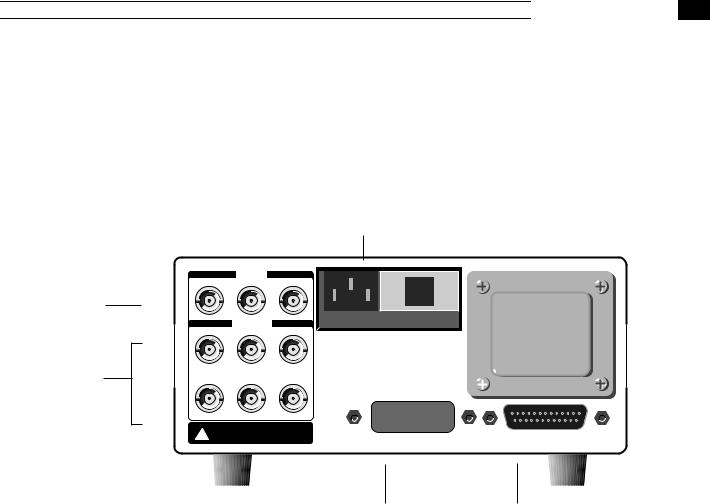
Rear Panel Features
1
2
3
INPUTS
TRIGGER |
AM(EXT) |
TIMEBASE |
TTL |
0-5V |
10MHz |
|
OUTPUTS |
|
TRIGGER |
MODULATION |
10MHz |
TTL |
0-5V |
1V |
SWEEP |
MARKER |
BLANK/LIFT |
0-10V |
TTL |
TTL |
WARNING: No user serviceable parts inside.
!Refer to operation manual for safety notice. For use by qualified laboratory personnel only.
FUSE: 3/4A (100/120VAC) or 3/8A (220/240VAC)
|
|
|
|
|
|
|
|
|
|
|
|
|
|
|
|
|
|
|
|
|
|
|
|
|
|
|
|
|
|
|
|
|
|
|
|
|
|
|
|
|
|
|
|
|
|
|
|
|
|
|
|
|
|
|
|
|
|
|
|
|
|
|
|
|
|
|
|
|
|
|
|
|
|
|
|
|
|
|
|
|
|
|
|
|
|
|
|
|
|
|
|
|
|
|
|
|
|
|
|
IEEE-488 STD PORT (GPIB) |
|
|
|
|
RS232 (DCE, 8d, 0p, 2s bits) |
||||
4 |
5 |
1) Power Entry Module |
This contains the DS345's fuse and line voltage selector. Use a 3/4 amp fuse |
|
for 100/120 volt operation, and a 3/8 amp fuse for 220/240 volt operation. To |
|
set the line voltage selector for the correct line voltage first remove the fuse. |
|
Then, remove the line voltage selector card and rotate the card so that the |
|
correct line voltage is displayed when the card is reinserted. Replace the |
|
fuse. |
2) External Inputs |
|
Trigger Input |
The trigger input is a TTL compatible input used to trigger modulation sweeps |
|
and bursts. This input has a 10 kΩ input impedance. The shield of this input is |
|
tied to that of the function output and may be floated up to ±40V relative to |
|
earth ground. |
AM Input |
The AM input controls the amplitude of the function output. This input has a |
|
100 kΩ input impedance and a ±5V range, where +5V sets the output to |
|
100% of the front panel setting, 0V sets the output to 0, and -5V sets the out- |
|
put to -100% of the setting. The 0 to 5V range is used for normal AM opera- |
|
tion, while the ±5V range is used for DSBSC modulation. This input is always |
|
active and should only be be connected if AM is desired. The shield of this in- |
|
put is tied to the shield of the function output and may be floated up to ±40V |
|
relative to earth ground. |
|
2-7 |


 DS345 FEATURES
Timebase Input |
This 1kΩ impedance input allows the DS345 to lock to an external timebase. |
|
The external source should be greater than 1V pk-to-pk and should be within |
|
±2 ppm of 10 MHz or any subharmonic down to 1.25 MHz. The shield of |
|
this input is connected to earth ground. |
3) Auxiliary Outputs |
|
10 MHz Output |
This output produces a >1V pk-pk 10 MHz sinewave from the DS345's inter- |
|
nal oscillator. It expects a 50Ω termination. The shield of this output is |
|
connected to earth ground. |
Modulation Out |
This output generates a 0 - 5V representation of the current modulation func- |
|
tion. The shield of this output is tied to that of the function output and may be |
|
floated up to ±40V relative to earth ground. |
Trigger Output |
This TTL compatible output goes high when a triggered sweep or burst be- |
|
gins, and goes low when it ends. This may be used to synchronize an exter- |
|
nal device to the sweep/burst. The shield of this output is tied to that of the |
|
function output and may be floated up to ±40V relative to earth ground. |
Sweep Output |
This output generates a 0 - 10 V ramp that is synchronous with the DS345's |
|
frequency sweep. The shield of this output is tied to that of the function out- |
|
put and may be floated up to ±40V relative to earth ground. |
Marker Output |
This TTL compatible output goes high when the DS345's frequency sweep |
|
passes the start marker frequency, and goes low when the sweep passes the |
|
stop marker frequency. The shield of this output is tied to that of the function |
|
output and may be floated up to ±40V relative to earth ground. |
Blank/Lift Out |
This TTL compatible output is low during the upsweep of a frequency sweep, |
|
and is high during the sweep retrace. The shield of this output is tied to that |
|
of the function output and may be floated up to ±40V relative to earth ground. |
4) GPIB Connector |
If the DS345 has the optional GPIB/RS232 interface this connector is used |
|
for IEEE-488.1 and .2 compatible communications. The shield of this con- |
|
nector is connected to earth ground. |
5) RS232 Connector |
If the DS345 has the optional GPIB/RS232 interface this connector is used |
|
for RS232 communication. The DS345 is a DCE and accepts 8 bits, no pari- |
|
ty, 2 stop bits and 300 and 19.2k Baud. The shield of this connector is |
|
connected to earth ground. |
2-8
DS345 OPERATION
Introduction |
The following sections describe the operation of the DS345. The first section |
|
describes the basics of setting the function, frequency, amplitude, and offset. |
|
The second section explains sweeps and modulation. The third section ex- |
|
plains storing and recalling setups, running self-test and autocalibration, and |
|
setting the computer interfaces. The fourth and last section describes front |
|
panel editing of arbitrary waveforms. |
Power-On |
When the power is first applied to the DS345 the unit will display its serial |
|
number and ROM version for about three seconds. The DS345 will then ini- |
|
tiate a series of self-tests of the circuitry and stored data. The test should |
|
take about three seconds and end with the message "TEST PASS". If the |
|
self test fails the DS345 will display an error message indicating the nature of |
|
the problem (see the TROUBLESHOOTING section for more details, page 4- |
|
1). The DS345 will attempt to operate normally after a self-test failure, (press- |
|
ing any key will erase the error message). |
SETTING THE FUNCTION
SYNC |
|
|
TRIG'D |
|
|
|
|
|
|
|
FREQ |
|
|
NOISE |
TTL |
|
TTL |
|
|
|
ARB |
AMPL |
|
FUNCTION |
|
ECL |
|
|
|
|
OFFST |
|
|
|
REL=O |
40V max |
50 Ω |
|
PHASE |
OUTPUTS |
The FUNCTION and SYNC BNCs are the DS345's main outputs. Both of |
|
these outputs are fully floating, and their shields may be floated relative to |
|
earth ground by up to ±40V. Both outputs also have a 50Ω output impe- |
|
dance. If the outputs are terminated into high impedance instead of 50Ω the |
|
signal levels will be twice those programmed (the FUNCTION output may |
|
also show an increase in waveform distortion). The programmed waveform |
|
comes from the FUNCTION output, while the SYNC output generates a TTL |
|
compatible (2.5 V into 50Ω) signal that is synchronous with the function out- |
|
put. The SYNC signal is suppressed if the function is set to NOISE or |
|
BURST modulation. If the function is set to ARB the SYNC signal is a 25ns |
|
negative going pulse at the start of each waveform. |
2-9


 Function Setting
FUNCTION SELECTION |
The DS345's output function is selected using the FUNCTION UP/DOWN ar- |
||||
|
row keys. Simply press the keys until the desired function LED is lit. If the |
||||
|
programmed frequency is outside of the range allowed for the selected func- |
||||
|
tion, an error message will be displayed and the frequency will be set to the |
||||
|
maximum allowed for that function. If modulation is enabled and the modula- |
||||
|
tion type or parameters are incompatible with the new function, an error mes- |
||||
|
sage will be displayed and the modulation will be turned off (the parameters |
||||
|
will not be altered). |
|
|
|
|
Ramps |
Ramp functions usually ramp up in voltage, however, downward ramps may |
||||
|
be programmed with the output invert function (see AMPLITUDE section). |
||||
Arbitrary Functions |
Arbitrary functions may be created on a computer and downloaded to the |
||||
|
DS345 via the computer interfaces, or they may be created using the |
||||
|
DS345's front panel editing functions. Arbitrary waveforms normally repeat |
||||
|
continuously, single triggering and burst triggering of arbitrary waveforms is |
||||
|
accomplished using the DS345's BURST modulation function. (See the AR- |
||||
|
BITRARY WAVEFORM EDITING section for more detail.) |
||||
FREQUENCY |
To display the DS345's output frequency press [FREQ]. The frequency is al- |
||||
|
ways displayed in units of Hz. The DS345 has 1 µHz frequency resolution at |
||||
|
all frequencies, for all functions. The maximum frequency depends on the |
||||
|
|
|
|
|
|
|
|
Function |
|
Frequency Range |
|
|
|
Sine |
|
1 µHz → 30.200000000000 MHz |
|
|
|
Square |
|
1 µHz → 30.200000000000 MHz |
|
|
|
Triangle |
|
1 µHz → 100,000.000000 Hz |
|
|
|
Ramp |
|
1 µHz → 100,000.000000 Hz |
|
|
|
Noise |
|
10 MHz White Noise (fixed) |
|
|
|
Arbitrary |
|
0.002329Hz → 40.0 MHz sampling |
|
|
|
|
|
|
|
|
function selected as listed below: |
||||
|
Frequency is usually displayed by the DS345 with 1 mHz resolution. Howev- |
||||
|
er, if the frequency is below 1 MHz and the microhertz digits are not zero the |
||||
|
DS345 will display the frequency with 1 µHz resolution. At frequencies great- |
||||
|
er than 1 MHz the digits below 1 mHz cannot be displayed, but the frequency |
||||
|
still has 1 µHz resolution and may be set via the computer interfaces or by |
||||
|
using the MODIFY keys with a step size less than 1 mHz. |
||||
|
If the function is set to NOISE the character of the noise is fixed with a band |
||||
|
limit of 10 MHz. The frequency is not adjustable and the FREQ display will |
||||
|
read "noise" instead of a numerical value. |
||||
|
If the function is set to ARB the frequency displayed is the sampling fre- |
||||
|
quency of the arbitrary waveform. This number is independent of the usual |
||||
|
frequency; it is the dwell time that the DS345 spends on each point in an ar- |
||||
|
bitrary waveform. This sampling frequency must be an integer submultiple of |
||||
|
the the 40 MHz clock frequency. That is, 40 MHz/N where N = 1,2,3... 234-1 |
||||
|
(40 MHz, 20 MHz, |
13.3333 MHz, 10 MHz, ...). The DS345 will spend |
|||
2-10


 Function Setting
|
|
1/Fsample on each point. When a new sampling frequency value is entered |
||||||
|
|
the DS345 will round the value to the nearest integer submultiple of 40 MHz. |
||||||
|
|
Note that the frequency for the standard functions is never rounded. |
|
|||||
Setting the Frequency |
|
To set the frequency of any function simply type a new value on the keypad |
||||||
|
|
and complete the entry with the appropriate units (Hz, kHz, or MHz). The |
||||||
|
|
MODIFY keys may be used to increase or decrease the frequency by the cur- |
||||||
|
|
rent step size. Press [STEP SIZE] key to display and change the step size. |
||||||
AMPLITUDE |
|
Pressing [AMPL] displays the amplitude of the output function. The amplitude |
||||||
|
|
may be set and displayed in units of Vpp, Vrms, and dBm. The current units |
||||||
|
|
are indicated by the LEDs at the right of the display. The amplitude range is |
||||||
|
|
limited by the DC offset setting since |Vac peak| + |Vdc| ≤ 5 V. If the DC offset |
||||||
|
|
is zero the amplitude range for each of the functions is shown below: |
|
|||||
|
|
note: The rms and dBm values for NOISE are based on the total power in the |
||||||
|
|
output bandwidth (about 10 MHz) at a given peak to peak setting. |
|
|||||
|
|
|
|
|
|
|||
|
|
|
Vpp |
Vrms |
dBm (50Ω) |
|||
|
Function |
Max. |
Min. |
Max. |
Min. |
Max. |
Min. |
|
|
|
|
|
|
|
|
|
|
|
Sine |
10V |
10 mV |
3.54V |
3.54 mV |
+23.98 |
-36.02 |
|
|
Square |
10V |
10 mV |
5V |
5 mV |
+26.99 |
-33.0 |
|
|
Triangle |
10V |
10 mV |
2.89V |
2.89 mV |
+22.22 |
-37.78 |
|
|
Ramp |
10V |
10 mV |
2.89V |
2.89 mV |
+22.22 |
-37.78 |
|
|
Noise |
10V |
10 mV |
2.09V |
2.09 mV |
+19.41 |
-40.59 |
|
|
Arbitrary |
10V |
10 mV |
n.a. |
n.a. |
n.a. |
n.a. |
|
|
|
|
|
|
|
|||
|
|
|
||||||
|
|
Arbitrary function amplitude may only be set in units of Vpp. The output sig- |
||||||
|
|
nal will briefly go to zero as the output attenuators are switched. |
|
|||||
|
|
|
||||||
|
|
The units of the amplitude display may be switched between Vpp, Vrms, and |
||||||
|
|
dBm without changing the actual amplitude by pressing the corresponding |
||||||
|
|
units key. When the DS345 is switched from one function to another the |
||||||
|
|
peak-to-peak amplitude is held constant. If the DC offset is zero, the ampli- |
||||||
|
|
tude may be set with three digits of resolution. If the DC offset is not zero the |
||||||
|
|
larger of the amplitude and the offset determines the resolution of both pa- |
||||||
|
|
rameters. The amplitude display is automatically adjusted such that all of the |
||||||
|
|
digits that may be changed are displayed. |
|
|
|
|||
Output Inversion |
|
For ramp and arbitrary functions the DS345's output may be inverted. This is |
||||||
|
|
useful for turning positive ramps into negative ramps, or inverting arbitrary |
||||||
|
|
waveforms. Pressing [AMPL] two times displays the invert enable option. |
||||||
|
|
Use the UP/DOWN MODIFY keys to enable or disable the inversion. |
|
|||||
D.C. Only |
|
The output of the DS345 may be set to a DC level by entering an amplitude |
||||||
|
|
of 0V. When the amplitude is set to zero the A.C. waveform will be off and |
||||||
|
|
the DS345 may be used as a DC voltage source. If the amplitude is zero the |
||||||
|
|
display will read "no AC" when the units are set to dBm. |
|
|
||||
TTL Settings |
|
Pressing [SHIFT][TTL] sets the output amplitude and offset to TTL values. |
||||||
2-11


 Function Setting

|
TTL levels are 5 Vpp with a 2.5V offset (the output will swing between 0 and |
|
+5V). |
ECL Settings |
Pressing [SHIFT][ECL] sets the output amplitude and offset to ECL values. |
|
ECL levels are 1 Vpp with a -1.3V offset (the output will swing between -1.8V |
|
and -0.8V). |
DC OFFSET |
The DC offset may range between ±5V, but is restricted such that |Vac peak| |
|
+ |Vdc| ≤ 5 V. When [OFFST] is pressed a new value may be entered using |
|
any amplitude unit key, the Vpp indicator LED will be lit . When the offset is |
|
changed the output signal will briefly go to zero as the output attenuators are |
|
switched. If the amplitude is zero, the offset may be set with three digits of |
|
resolution. If the amplitude is not zero the larger of the amplitude and offset |
|
determines the resolution of both parameters. The offset display is automati- |
|
cally adjusted such that all of the digits that may be changed are displayed. |
PHASE |
Press [PHASE] to display and modify the phase of the FUNCTION output. |
|
Phase is always measured with respect to the internal timebase, not the |
|
SYNC output. The phase may be changed with the keypad and the DEG unit |
|
key, or using the MODIFY keys. The range of the phase setting is |
|
±7199.999° and may be set with 0.001° resolution. If the function is set to |
|
NOISE, ARB, or modulation is enabled in SWEEP, FM, or PM modes the |
|
phase cannot be changed and the message "no Phase" will be displayed. In |
|
BURST modulation mode the PHASE function will set the waveform phase |
|
at the start of the burst. This is quite useful for starting the burst at a particu- |
|
lar point in the waveform. |
Zero Phase |
The current phase may be assigned the value zero by pressing [SHIFT] |
|
[REL=0]. Subsequent changes to phase will be relative to this value. |
2-12

SWEEPS AND MODULATION
Introduction |
This section of the manual describes the DS345's modulation capabilities. |
|
The DS345 has extremely powerful and flexible built-in modulation functions. |
It is capable of AM (both simple and double sideband suppressed carrier (DSBSC)), FM, PM, tone bursts, and frequency sweeps. The modulation waveform may be a sine, square, ramp, or triangle wave. Frequency can be swept up or down at a linear or logarithmic rate. A built-in trigger generator allows triggering of single sweeps and bursts. For additional flexibility the DS345 can also modulate the output waveform with an arbitrary pattern of amplitude, frequency, or phase values.
SWEEP/MODULATE
LIN SWP |
SINGLE |
MOD/SWP |
|||
LOG SWP |
|
|
|
|
|
|
|
SWEEP |
|
||
AM (INT) |
|
|
|
||
|
|
ON/OFF |
|
||
FM |
|
|
|
||
|
|
|
|
||
|
BRST CNT |
||||
I m |
|
||||
ARB |
|
RATE |
|
||
BURST |
|
|
|||
|
|
|
|||
|
|
TRIG |
|
|
|
|
|
|
SWP CF |
||
|
|
|
|
SPAN |
|
|
|
|
|
(DEPTH) |
|
|
|
|
|
STOP f |
|
|
|
|
|
START |
|
|
|
|
|
FREQ |
|
|
|
|
|
|
|
MODULATION ON/OFF |
The SWEEP ON/OFF key enables the DS345's modulation functions. Press- |
|
ing the key toggles the modulation status. When modulation is on the |
|
[MOD/SWP] LED will light. When modulation is enabled the modulation type |
|
and modulation parameters are checked for consistency with the selected |
|
output function. If the selected modulation is illegal (for example, FM frequen- |
|
cy out of range for the function) the DS345 will display an error message and |
|
not enable the modulation. The erroneous value must be changed before the |
|
modulation is turned on. |
MODULATION TYPE |
The type of modulation is selected using the MODULATION TYPE [UP/ |
|
DOWN] arrow keys. Most of the output functions can be modulated by any |
|
type of modulation. However, NOISE can only be modulated by the external |
|
AM input, and ARB waveforms can only be modulated by AM and BURST |
|
modulations. If an invalid choice is selected the message "funct error" is dis- |
|
played. |
MODULATION WAVEFORM |
The waveform of the modulating function is selected with MODULATION |
|
WAVEFORM UP/DOWN arrow keys. If no LEDs are lit the selected modula- |
|
tion type has no associated waveform (BURST, for example, has no modula- |
|
tion waveform). Not all modulation types may use all modulation waveforms. |
|
The allowable combinations are listed on the following page. Note that ARB |
|
modulation waveforms can only be downloaded via the computer interfaces. |
2-13
 Loading...