


MODEL SR620
Universal Time Interval Counter
1290-D Reamwood Avenue
Sunnyvale, California 94089
Phone: (408) 744-9040 • Fax: (408) 744-9049 email: info@thinkSRS.com • www.thinkSRS.com
Copyright © 1989 by SRS, Inc.
All Rights Reserved.
Revision 2.7 (2/2006)

SR620 Universal Time Interval Counter

Table of Contents i
Table of Contents
Condensed Information |
|
Safety and Use |
v |
SRS Symbols |
vi |
Specifications |
vii |
Abridged Command List |
xi |
Operation |
|
Quick Start Instructions |
1 |
Instrument Overview |
2 |
Front Panel Operation |
3 |
Choosing the Measurement |
3 |
Setting the Mode |
3 |
Setting the Source |
3 |
Setting the Arming Mode |
3 |
Setting the Number of Samples |
3 |
Starting Measurements |
3 |
Arming Mode Summary |
4 |
Choosing the Output Display |
5 |
Setting the Front Panel Display |
5 |
Graphics Outputs |
6 |
Graph Types |
6 |
Scaling Graphs |
6 |
Graphics Cursor |
6 |
Graphics Zoom |
6 |
Hardcopy Output |
7 |
Chart Outputs |
7 |
Setting the Inputs |
9 |
Setting Trigger Levels |
9 |
Setting Trigger Slopes |
9 |
Input Termination |
9 |
UHF Prescalers |
9 |
Input Coupling |
10 |
Reference Output |
10 |
Timebase Input and Output |
10 |
DVM Inputs |
10 |
Sample Arming |
11 |
TIME Mode |
11 |
Time Interval Arming |
11 |
+TIME |
11 |
+TIME, EXT |
12 |
+TIME, EXT with HOLDOFF |
12 |
+/-TIME |
12 |
+/-TIME, EXT |
12 |
Width Arming |
13 |
WIDTH:+TIME |
13 |
WIDTH:+TIME, EXT |
13 |
WIDTH:+TIME, EXT with HLDF |
13 |
Rise and Fall Time Arming |
13 |
RISE/FALL: +TIME |
13 |
RISE/FALL: EXT |
13 |
Frequency Arming |
14 |
Frequency Ratio |
14 |
Period Arming |
14 |
Period Ratio |
14 |
Phase Arming |
14 |
Count Arming |
15 |
Count Ratio |
15 |
Delayed Arming Modes |
15 |
Configuration Menus |
17 |
CONTROL Menu |
17 |
GPIB Parameters |
17 |
RS232 Parameters |
17 |
CALIBRATION Menu |
17 |
AutoCal |
18 |
Clock Source |
18 |
OUTPUT Menu |
18 |
Graphics Enable |
18 |
Printer/Plotter Control |
18 |
Jitter Type Selection |
19 |
Gate Scale Multiplier |
19 |
Trigger Knob Range |
19 |
SCAN Menu |
19 |
Enabling Scans |
19 |
Setting D/A outputs |
20 |
Scanning the D/A's |
20 |
External Trigger Delays |
20 |
Scan Examples |
20 |
Specification Guide |
23 |
Definition of Terms |
23 |
Least Significant Digit |
23 |
Resolution |
23 |
Error |
23 |
Differential Non-linearity |
23 |
SR620 Universal Time Interval Counter

ii Table of Contents
Timebase Specifications |
24 |
Short-Term Stability |
24 |
Long-Term Stability |
24 |
External Timebases |
25 |
Trigger Input Specifications |
25 |
Measurement Accuracy |
26 |
Programming |
|
Programming the SR620 |
29 |
Communications |
29 |
GPIB Communication |
29 |
RS-232 Communication |
29 |
Data Window |
29 |
Command Syntax |
29 |
Detailed Command List |
30 |
Trigger Commands |
30 |
Measurement Control |
31 |
Data Transmission |
32 |
Binary Dump |
33 |
Scan Control |
34 |
Graphics Control |
35 |
Front Panel Control |
36 |
Interface Control |
37 |
Status Reporting |
39 |
Calibration Commands |
39 |
Serial Poll Status Byte |
40 |
Event Status Byte |
41 |
TIC Status Byte |
41 |
Error Status Byte |
41 |
Programming Examples |
43 |
BASIC and RS-232 |
44 |
FORTRAN/National Instruments |
45 |
BASIC/GPIB/Binary Dump |
46 |
FORTRAN/GPIB/Binary Dump |
48 |
C/GPIB/Binary Dump |
52 |
Test and Calibration |
|
Troubleshooting Tips |
57 |
Troubleshooting |
57 |
Power-up Error Messages |
57 |
CAL Error Messages |
57 |
Common Operational Problems |
57 |
Error Messages |
57 |
Error Indicators |
58 |
Wrong Value |
58 |
Excessive Jitter |
58 |
Scope Display Problems |
58 |
Printer and Plotter Problems |
58 |
GPIB Interface Problems |
58 |
RS-232 Interface Problems |
59 |
Performance Tests |
61 |
Necessary Equipment |
61 |
Functional Tests |
61 |
Front Panel Test |
61 |
Self-Test |
61 |
Trigger Input Tests |
61 |
Counter Channel Tests |
62 |
Rear Panel Tests |
62 |
Performance Tests |
63 |
Timebase Frequency |
63 |
Accuracy |
63 |
Time Interval |
63 |
Trigger Sensitivity |
63 |
Trigger Accuracy |
64 |
D/A Output Accuracy |
64 |
DVM Input Accuracy |
64 |
Test Scorecard |
67 |
Calibration |
69 |
Overview |
69 |
Calibration Bytes |
69 |
Simple Calibration |
70 |
Complete Calibration |
70 |
Trigger Input Calibration |
70 |
Clock Oscillator Calibration |
71 |
Insertion Delay Calibration |
71 |
D/A Output Calibration |
72 |
DVM Input Calibration |
73 |
SR620 Circuitry |
|
Circuit Description |
75 |
Processor System |
75 |
GPIB Interface |
75 |
Printer Interface |
75 |
RS-232 Interface |
76 |
Scope Display |
76 |
Counter Input Ports |
76 |
Display Control Ports |
76 |
Front-End Status Bits |
77 |
ADC and DAC Control Bits |
77 |
REF OUT |
78 |
Delay and Gate Generator |
78 |
SR620 Universal Time Interval Counter

Table of Contents iii
Timebase |
79 |
Front-End Inputs |
79 |
Trigger Multiplexers |
80 |
Frequency Gates |
80 |
Event Gating |
81 |
Counting Channels |
81 |
Fast Time Interval Logic |
82 |
Time Interval Arming |
82 |
Time Integrators |
83 |
Analog to Digital Converter |
83 |
Autolevel Circuits |
83 |
Digital to Analog Converter |
84 |
Unregulated Power Supplies |
84 |
Power Supply Regulators |
84 |
Power Supply Bypass |
85 |
Front Panel Display PCB |
85 |
Component Parts List |
87 |
Schematic Circuit Diagrams |
Sheet No. |
Front/Rear Panel Summary |
|
Counter Visual Index |
|
Microprocessor System |
1/16 |
GPIB/RS232/Printer Interfaces |
2/16 |
Scope Graphics Controller |
3/16 |
I/O Ports and LED Drivers |
4/16 |
Analog and ECL I/O |
5/16 |
Slow Counters and REF OUT |
6/16 |
Fast Clocks and Timebase |
7/16 |
Front-End Input Comparators |
8/16 |
ECL Mpx/Freq Gating/Counters |
9/16 |
Fast Time Interval Logic |
10/16 |
Time Interpolators |
11/16 |
A/D, D/A and Threshold pots |
12/16 |
Unregulated Power Supplies |
13/16 |
Power Supply Regulators |
14/16 |
Spares and Decoupling |
15/16 |
Front Panel Display PCB |
16/16 |
Component Placement on PCB |
|
SR620 Universal Time Interval Counter

iv Table of Contents
SR620 Universal Time Interval Counter

Safety and Preparation for Use v
Safety and Preparation for Use
WARNING: Dangerous voltages, capable of causing death, are present in this instrument. Use extreme caution whenever the instrument covers are removed.
This instrument may be damaged if operated with the LINE VOLTAGE SELECTOR set for the wrong ac line voltage or if the wrong fuse is installed.
LINE VOLTAGE SELECTION
The SR620 operates from a 100V, 120V, 220V, or 240V nominal ac power source having a line frequency of 50 or 60 Hz. Before connecting the power cord to a power source, verify that the LINE VOLTAGE SELECTOR card, located in the rear panel fuse holder, is set so that the correct ac input voltage value is visible.
Conversion to other ac input voltages requires a change in the fuse holder voltage card position and fuse value. Disconnect the power cord, open the fuse holder cover door and rotate the fuse-pull lever to remove the fuse. Remove the small printed circuit board and select the operating voltage by orienting the printed circuit board to position the desired voltage to be visible when pushed firmly into its slot. Rotate the fuse-pull lever back into its normal position and insert the correct fuse into the fuse holder.
LINE FUSE
Verify that the correct line fuse is installed before connecting the line cord. For 100V/120V, use a 1 Amp fuse and for 220V/240V, use a 1/2 Amp fuse.
LINE CORD
The SR620 has a detachable, three-wire power cord for connection to the power source and to a protective ground. The exposed metal parts of the instrument are connected to the outlet ground to protect against electrical shock. Always use an outlet which has a properly connected protective ground.
CONNECTION TO OTHER INSTRUMENTS
All front panel BNC shields are connected to the chassis ground and to the power outlet ground via the power cord. Do not apply any voltage to either the shields or to the outputs. The outputs are not protected against connection to any potential other than ground.
SR620 Universal Time Interval Counter

vi Safety and Preparation for Use
SR620 Universal Time Interval Counter

|
|
Specifications |
vii |
Specifications |
|
|
|
Functions |
Time Interval, Pulse Width, Rise and Fall Times, Frequency, Period, Phase, |
||
|
and Event Counting. |
|
|
|
Measurement statistics (mean, min, max, standard deviation or Allan |
||
|
variance) and graphics are available in all modes of operation. |
|
|
Time Interval |
Time, Width, Rise and Fall Times |
|
|
Range |
-1000 to +1000 s in +/- TIME mode; -1 ns to +1000 s in all other modes |
|
|
Trigger Rate |
0 to 100 MHz |
|
|
Least Significant Digit |
4 ps single sample, 1 ps with averaging |
|
|
Resolution |
(((25 ps typ [50 ps max] )2+ (0.2 ppb x Interval)2) / N)1/2 rms |
|
|
|
(((25 ps typ [50 ps max])2 + (0.05 ppb x Interval)2) / N)1/2 rms (Opt 01) |
|
|
Error |
< ±(500ps typ [1 ns max] + Timebase Error x Interval +trigger error) |
|
|
|
< ±(50ps typ[100ps max] + Timebase Error x Interval) (REL) |
|
|
Arming Modes |
+TIME |
Stop is armed by Start |
|
|
+TIME EXT |
Ext arms Start |
|
|
+TIME EXT HOFF |
Leading EXT edge arms Start, trailing EXT edge arms |
|
|
|
Stop. |
|
|
±TIME |
Armed by Start/Stop pair |
|
|
±TIME CMPL |
Armed by Stop/Start pair |
|
|
±TIME EXT |
Armed by EXT input edge |
|
|
EXT arming may be internally delayed or scanned with respect to the EXT |
||
|
input in variable steps. The step size may be set in a 1,2,5 sequence from 1 |
||
|
µs to 10 ms. The maximum delay is 50,000 steps. |
|
|
Display |
16 digit fixed point with 1 ps LSD |
|
|
Sample Rate |
For a sample size of N, the total sample time is N x(800 µs + measured time |
||
|
interval) + Calculation time. |
|
|
|
The calculation time occurs only after N measurements are completed and |
||
|
varies from zero (N=1, no graphics, binary responses) to 5 ms (N=1, no |
||
|
graphics) to 10 ms (display mean or std dev) to 60 ms (display histogram). |
|
|
Frequency |
|
|
|
Range |
0.001 Hz to 300 MHz via comparator inputs. |
|
|
|
40 MHz to 1.3 GHz via internal UHF prescalers. |
|
|
|
RATIO A/B range: 10-9 to 103 |
|
|
Error |
< ± ((100ps typ [350 ps max])/Gate + Timebase Error ) x Frequency |
|
|
Gates |
External, 1 period, 1ms to 500s in 1,2,5 sequence. Gates may be externally |
||
|
triggered with no delay. Gates may be delayed relative to an EXTernal |
||
|
trigger. The delay from trigger may be set from 1 to 50,000 gate widths. |
|
|
Display |
16 digit fixed point with LSD = Freq x 4ps/Gate. 1 µHz max. resolution |
(1 |
|
|
nHz with x1000 for frequencies ≤ 1 MHz) |
|
|
Period |
|
|
|
Range |
0 to 1000 seconds. RATIO A/B range: 10-9 to 103 |
|
|
Error |
< ±((100 ps typ [350ps max])/Gate + Timebase Error) x Period |
|
|
Gates |
Same as frequency |
|
|
Display |
16 digit fixed point with LSD = 1 ps (1 fs with x1000 for periods ≤ 1 s) |
|
|
Phase |
Phase = 360 x (Tb - Ta) / Period A |
|
|
Range |
-180 to +180 degrees (0 to 100 MHz frequency) |
|
|
Resolution |
(25ps x frequency x 360 + 0.001) degree |
|
|
SR620 Universal Time Interval Counter

viii Specifications
Gate |
0.01 seconds (1 period min.) for period measurement and 1 sample for time |
|
|
interval measurement. Period may also be measured using externally |
|
|
triggered internal gates as in frequency mode. |
|
Error |
< ±(1ns x Frequency x 360 + 0.001) degree |
|
Events |
|
|
Range |
1012. RATIO A/B range: 10-9 to 103 |
|
Count Rate |
0 to 300 MHz |
|
Gates |
Same as frequency |
|
Display |
12 digits |
|
Timebase |
|
|
|
Standard |
Option/01 |
Frequency |
10.000 MHz |
10.000 MHz |
Type |
TCVCXO |
Ovenized VCXO |
Aging |
1x10⁻⁶/yr |
5x10⁻¹⁰/day |
Allan Variance (1s)(typ.) |
3x10⁻¹⁰ |
5x10-12 |
Stability 0-50° C |
1 ppm |
0.002 ppm |
Settability |
0.01 ppm |
0.001 ppm |
External |
User may supply 5 or 10 MHz timebase. 1 Volt nominal. |
|
Inputs |
A, B, and EXTernal |
|
Threshold |
-5.00 to +5.00 VDC with 10 mV resolution |
|
Accuracy |
15mV + 0.5% of setting |
|
Sensitivity |
see graph next page |
|
Autolevel (A&B) |
Threshold set between peak input excursions. (f>10 Hz, duty cycle >10-6) |
|
Slope |
Rising or falling edge |
|
Impedance |
(1 M Ohm + 30 pf) or 50 Ohms. 50 Ohm termination has SWR < 2.5:1 from |
|
|
0 -1.3GHz |
|
Coupling |
AC or DC. Ext is always DC coupled. |
|
Input Noise |
350mV rms typical |
|
Bandwidth |
300 MHz BW provides 1.2 ns risetime |
|
Prescaler (A&B) |
see graph next page |
|
Protection |
100 V. 50 Ohm terminator is released if input exceeds ±5 Vpeak. |
|
REF Output |
Calibration and Trigger source |
|
Frequency |
1.00 KHz (Accuracy same as timebase) |
|
Rise/Fall |
2 ns |
|
Amplitude |
TTL: 0 to 4 VDC (2 VDC into 50 Ohms) |
|
|
ECL: -1.8 to -0.8 VDC into 50 Ohms |
|
DVM Inputs |
Two differential rear panel DVM inputs |
|
Full Scale |
±1.999 or ±19.99 VDC |
|
Type |
Sample & hold with successive approximation converter |
|
Impedance |
1 M Ohm |
|
Accuracy |
0.3% of full scale |
|
Speed |
Formatted response in approximately 5 ms. |
|
D/A Outputs |
Two rear panel outputs which may be ramped |
|
Full Scale |
±10.00 VDC |
|
Resolution |
5 mV |
|
Impedance |
< 1 Ohm |
|
SR620 Universal Time Interval Counter
Specifications ix
Default |
Voltage proportional to Mean & Deviation |
Accuracy |
0.3% of full scale |
Graphics |
Live scope displays and hardcopy |
Scope |
Two rear panel outputs to drive x-y scope |
Displays |
Histograms and strip charts of mean & deviation |
X-axis |
-5 to +5 V for 10 division deflection |
Y-axis |
-4 to +4 V for 8 division deflection |
Resolution |
250 (H) x 200 (V) pixels |
Hardcopy |
Via Centronics port to Epson graphics compatible dot matrix printers. |
|
RS-232, IEEE-488 to HP-GL compatible Digital Plotters. |
Interfaces |
|
RS-232C |
300 to 19.2 KBaud. All instrument functions may be controlled. |
|
PC compatible serial cable. |
GPIB |
IEEE-488 compatible interface. All instrument functions may be controlled. |
Speed |
Approximately 150 ASCII formatted responses per second. |
|
1400 binary responses per second. |
General |
|
Operating |
0 to 50° C |
Power |
100, 120, 220 or 240 VAC +5% -10%. 50/60 Hz. 70 Watts. |
Dimensions |
14" x 14" x 3.5". Rack mounting hardware included. |
Weight |
11 lbs |
SR620 Universal Time Interval Counter

x Specifications
SR620 Universal Time Interval Counter

Abridged Command List xi
Abridged Command List
Syntax
Variable i is an integer that selects an input channel for the command:
i Channel
0External Gate
1A input
2B input
Variables i,j,k,l,m, and n are all integers.Variable x is a real number in integer,real, or exponential notation.
Commands which may be queried have a ? in parentheses (?) after the mnemonic. The ( ) are not sent. Commands that may only be queried have a '?' after the mnemonic. Commands which may not be queried have no '?'. Optional parameters are enclosed by {}.
Trigger Control Commands |
|
|
LEVL(?) i,x |
Set channel i threshold to x volts. Only allowed in remote operation. |
|
MTRG j |
Same as pushing MAN trigger button. In external gate or holdoff arming |
|
|
modes n=0= start gate, n=1= stop gate. Otherwise n is ignored. |
|
RLVL(?) j |
Sets the reference output level to 0 = ecl,1=ttl. |
|
TCPL(?) i{,j} |
Sets the input ac/dc coupling of chans A and B to 0 = dc, or 1 = ac. |
|
TERM(?) i{,j} |
Sets the 50 ohm terminator of input, also prescaler n=0= 50 ohm, n=1= 1 |
|
|
meg, n= 2 = prescale. Prescalers can only be used in freq and per modes. |
|
TMOD(?) i{,j} |
Sets autolevel on/off. 0 = auto off, 1 = auto on. |
|
TSLP(?) i{,j} |
Set the trigger slope to 0 = positive, 1 = negative. |
|
Measurement Control Commands |
|
|
*TRG |
Device trigger, same as pushing start button |
|
ARMM(?) j |
Sets the arming mode |
|
|
0 |
+- time |
|
1 |
+ time |
|
2 |
1 period |
|
3 |
0.01 s gate |
|
4 |
0.1 s gate |
|
5 |
1.0 s gate |
|
6 |
ext trig +- time |
|
7 |
ext trig + time |
|
8 |
ext gate/trig holdoff |
|
9 |
ext 1period |
|
10 |
ext 0.01 s gate |
|
11 |
ext 0.1 s gate |
|
12 |
ext 1.0s gate |
AUTM(?) j |
Sets/resets autostart of measurements. 0 = off,1= on |
|
COMP |
Complements parity in +-time arming |
|
DREL(?) j |
Sets/clears the display REL. 0 = clear, 1 = set, 2 = clear REL and display, 3= |
|
|
set rel to position of cursor. |
|
GATE(?) x |
Sets the value of the frequency, period, of count gate to x. x may bebetween |
|
|
1ms and 500s in a 1,2,5 sequence. If x < 0 a externally triggered gate of |
|
|
length x is set. |
|
JTTR(?) j |
Sets variance type to 0 = std dev, 1= Allan variance. |
|
SR620 Universal Time Interval Counter

xii Abridged Command List
MODE(?) j |
Sets the instrument mode to 0 = time,1 = width, 2=tr/tf, 3 = freq, 4 = period, 5 |
|
= phase, 6 = count. |
SIZE(?) j |
Sets the number of samples. |
SRCE(?) j |
Sets the measurement source to 0 = A, 1= B, 2= REF, 3 = ratio. |
STRT |
Same as pushing start button. |
STOP |
Same as pushing stop button. |
Data Commands |
|
MEAS? j |
Startts a measurement and returns the result when it is complete. If j=0 the |
|
mean is returned, j=1 returns the jitter, j=2 returns the max, and j=3 the min. |
XALL? |
Returns mean,rel,jitter,max,min of a measurement. |
XAVG? |
Returns the mean of measurement. |
XJIT? |
Returns the jitter of a measurement. |
XMAX? |
Returns the max of a measurement. |
XMIN? |
Returns the min of a measurement. |
XREL(?) x |
Sets the value of the display rel to x. |
XHST? j |
Returns section j of the histogram display as 4 byte binary integers.j=0 to 9. |
HSPT? j |
Return the value of the point n on the histogram. j=1 to j = 250. Returns |
|
9E20 if graph is blank. |
SCAV? j |
Returns the value of point n (1 - 250) of the mean stripchart or the value of |
|
scan point j. returns 9E20 if the stripchart is blank or the scan has not |
|
reachedpoint j. |
SCJT? j |
Returns the value of point n (1 - 250) of the jitter stripchart or the value of |
|
scan point j. returns 9E20 if the stripchart is blank or the scan has not |
|
reached point j. |
BDMP j |
Binary dumps j points. Sample size = 1. |
Scan Commands |
|
ANMD(?) j |
Sets the DAC output mode of the mean and jitter DAC's to 0 = chart/chart, 1= |
|
DAC/chart, 2= chart/DAC,3 = DAC/DAC. |
DBEG(?) j |
Sets the delay scan start position to 1-50000 step sizes after the external |
|
trigger |
DSEN(?) j |
Enables the internal delay scan . 0 = delay off, 1=delay hold, 2 = delay scan. |
DSTP(?) x |
Sets the delay scan step size to 1,2,5 x 10 -2,-3,-4,-5,-6. 1 x 10 –2 is the |
|
maximum step size. |
HOLD(?) x |
Sets the hold time between scan points from .01s to 1000 s in .01 s steps |
SCAN |
Clears and restarts a scan. |
SCEN(?) j |
Enables scanning. 0 = disabled,1= single scan mode 2 = repeat scan mode |
SCLR |
Clears the scan. |
SLOC? |
Returns the number of the last completed scan point. Returns 0 if no points |
|
are complete. |
SCPT(?) j |
Sets number of scan points to 2,5,10,25,50,125,250. |
VBEG(?) j,x |
Sets the DAC output scan starting voltage. If scans are disabled or the step |
|
size is zero the output is immediately set to the new voltage. Otherwise, the |
|
voltage is updated at the start of the next scan. |
VOUT? j |
Reads the current output voltage of DAC channel j. |
VSTP(?) j,x |
Sets the DAC scan step size to x volts. |
Graphics Control Commands |
|
AUTP(?) j |
Sets the autoprint mode to 0 = off or 1 = on. |
AUTS |
Autoscales the displayed graph. |
CURS (?) j |
Sets the cursor position to j. |
DGPH(?) j |
Sets the displayed graph to 0 = histogram,1= mean,2 = jitter |
GCLR |
Clears the displayed graph. |
SR620 Universal Time Interval Counter

|
|
|
Abridged Command List xiii |
|
GENA(?) j |
Turns graphs 0 = off, 1 = on. |
|
||
GSCL(?) j,x |
Sets the graph scales. j = 0 = histogram verticalscale,j=1= histo |
|||
|
|
|
horizontal,j=2=histo bins,j=3= mean graph scale,j = 4= jitter graph scale. x = |
|
|
|
|
units per division or # bins. |
|
PDEV(?) j |
Sets output device to 0 = printer, 1= plotter. |
|||
PLAD(?) j |
Sets the plotter GPIB address. |
|||
PLPT(?) j |
Sets the plotter port to 0= RS232 , 1= GPIB. |
|||
PLOT |
|
|
Initiates a print/plot |
|
PCLR |
|
|
Clears plots/prints |
|
Front Panel Control |
|
|
||
DISP(?) j |
|
Sets the display source. 0=MEAN,1=REL,2=JITTER,3=MAX |
||
|
|
|
4 =MIN, 5 = TRIG, 6 = DVM's |
|
EXPD(?) j |
Set the x1000 expand status in freq and per mode 0 = off, 1 = on |
|||
KEYS(?) j |
Simulates a keypress, or reads the most recently pressed key |
|||
Rear Panel Control |
|
|
||
CLCK(?) j |
Sets the clock source. 0 = internal, 1= external. |
|||
CLKF(?) |
j |
Sets the external clock frequency. 0=10MHz,1= 5MHz. |
||
PORT(?) |
j |
Sets/reads the binary I/O port when enabled. |
||
PRTM(?) j |
Sets the printer port mode. 0 = print, 1 = input,2 =output. |
|||
RNGE(?) i{,j} |
Sets the full scale voltage of DVM input i. |
|||
VOLT? j |
|
Reads DVM channel 0 or 1. |
||
Interface Control Commands |
|
|
||
*RST |
|
|
Clears instrument to default settings. |
|
*IDN? |
|
|
Returns the device identification . |
|
*OPC(?) |
|
Operation complete common synchronization command. Either sets a status |
||
|
|
|
bit or returns a value when all operations (scans , prints, measurements) are |
|
|
|
|
complete. |
|
*WAI |
|
|
Wait synchronization command. Holds off further command execution until all |
|
|
|
|
in progress operations (scans, prints,measurements) are complete. |
|
ENDT |
{j,k,l,m} |
Sets the RS232 end transmission terminator |
||
LOCL |
j |
|
Sets the RS232 local/remote function. 0 = local, 1=remote, 2 = local lockout |
|
WAIT(?) j |
Sets the RS232 intercharacter time delay. |
|||
Status Reporting Commands |
|
|
||
*CLS |
|
|
Clears all status registers. |
|
*ESE(?) |
j |
Sets/reads the standard status byte enable register. |
||
*ESR? {j} |
|
Reads the standard status register, or just bit j of register. |
||
*PSC(?) j |
|
Sets the power on status clear bit. This allows SRQ'son power up if desired. |
||
*SRE(?) j |
|
Sets/reads the serial poll enable register. |
||
*STB? |
{j} |
Reads the serial poll register, or just bit n of register. |
||
EREN(?) |
j |
Sets/reads the error status enable register. |
||
ERRS? {j} |
Reads the error status register, or just bit n of register. |
|||
STAT? |
{j} |
Reads the TIC status register, or just bit n of register. |
||
TENA(?) j |
Sets/reads the TIC status enable register. |
|||
STUP? |
|
Returns the complete setup in one string. |
||
Calibration Control (NOTE: these commands are not needed during normal operation) |
||||
$TAC? j |
|
Reads the value of the time-to-amplitude converters. |
||
$PHK? j |
|
Sets the printer handshake lines. |
||
SR620 Universal Time Interval Counter

xiv Abridged Command List
$POT? j |
Reads the value of trigger pot j |
*CAL? |
Starts autocal and returns status when done. |
*TST? |
Starts self-test and returns status when done. |
BYTE(?) j,k |
Reads/sets linearization byte values. |
WORD(?) j,k |
Reads/sets cal words. |
SR620 Universal Time Interval Counter

Quick Start Instructions 1
Quick Start
Use this procedure as a quick orientation to the instrument's features and capabilities. If you encounter problems, read the detailed discussions on operation or see the troubleshooting section.
1)Make sure that the correct line voltage has been selected on the rear panel power entry module.
2)With the unit's power switch on "STBY", hold the "CLR" key in the "DISPLAY" section down and turn the unit "ON". This will return all of the instrument settings to their default state. The message, "SELF TEST PASS" should briefly appear.
Note: The fan will not run until the unit warms up. The red LED labeled "CLOCK" in the CONFIG section may stay on for a few minutes. The red LED's labeled "START" and "STOP" may blink if no inputs are applied.
3)Press the MODE down key once to select the WIDTH mode. Press the source key twice to select REF ( the 1 kHz REFerence ) as the signal source. After 1/2 hour warmup, the display should read 500 us +- 1 ns. If the displayed value is outside this range see instructions for running the AUTOCAL procedure.
4)Press the SAMPLE SIZE up-key five times to select a sample size of 500. This will slow the display update rate to 2 Hz, and provide a more consistent MEAN value.
5)Press the SET key in the DISPLAY section to set the REL offset to the current value of the
MEAN. The REL LED will turn on and the display will show a mean value within a few ps of zero. An 'r' appears on the display to indicate a relative value.
6)Press the DISPLAY down-key to show each of the following:
MEAN |
0+-100 ps (The REL is set) |
REL |
500 us +-100 ps |
JITTER |
5-20 ps |
MAX |
Erratic, but usually <100 ps |
MIN |
Erratic, but usually <100 ps |
TRIG |
+-5 V per the three level knobs |
DVM |
Within 5 mV of zero. |
7)Configure an oscilloscope for the X-Y display mode with the horizontal and vertical inputs set for dc coupling ( not 50 Ohms ) and 1 V/div sensitivity. If the scope has scale factor displays, turn them "off", and set the 20 MHz bandwidth limit. Center the beam in the middle of the screen and attach the inputs to the X-Y display outputs on the rear panel of the SR620.
8)Press the AUTO key in the SCOPE AND CHART section to scale the display. If the DISPLAY REL is set, the HISTOgram of the pulse widths will be displayed with about 20 ps/div horizontal resolution.
9)In the SCOPE AND CHART section, press the display button to change from HIST to MEAN. Press the AUTO button to scale the display. The scope will now show a 'strip chart' of the mean values for each set of measurements. Now select JITTER and press AUTO to display a 'strip-chart' of standard deviations for the scope display.
SR620 Universal Time Interval Counter

2 Instrument Overview
Introduction
The SR620 Time Interval Counter can do a variety of time interval and frequency measurements. The instrument's high single-shot timing resolution, low jitter, and reciprocal counting architecture allow rapid, high resolution measurements.
Modes of Operation
Time Intervals between the A and B inputs may be measured with 4 ps LSD, 25 ps rms resolution, 100 ps relative accuracy, and 1ns absolute accuracy. Time intervals from -1ns to 1000 s or +- 1000 s may be measured.
Pulse Widths of either input may be measured. The start and stop thresholds are set separately. The resolution, jitter, and accuracy are the same as for Time interval measurements.
Rise and Fall Times of either input may be measured. The start and stop thresholds may be set with 10 mV resolution. The 350 MHz bandwidth of the inputs allows measurements of rise and fall times down to 1 ns.
Frequencies from 0.001 Hz to 1.3 GHz may be measured. The SR620 will provide 11 digits of resolution when a one second gate is used. Frequencies above 300 MHz may be measured on either input using the UHF prescalers. NanoHertz resolution is available in the x1000 display mode.
Periods may be measured with femtosecond resolution. Period measurements are done the same way as frequency measurements, except the reciprocal of frequency is reported to the display.
The Phase between the signals on the A and B input may be measured with 0.001° resolution. The phase shift between signals from 0.001 Hz to 100MHz may be measured.
The Count mode is used to count input transistions during a gate. Count rates up to 300 MHz will be tallied.
Arming and Gating
Each of these modes are supported with powerful arming and gating modes. Time arming modes include: +Time, +Time External, +Time External with Stop Holdoff, +-Time, and +-Time External.
Frequency gating modes include fixed gates of one period, 0.01 s, 0.1 s, 1 s, Externally triggered fixed gates, External gates, Externally triggered adjustable gates from 1 us to 10 ms. Gates which are externally triggered may be delayed and scanned by 1 to 50,000 gate widths to allow transient frequency measurements.
Statistics
The SR620 will compute and display statistics for sample sizes of one to one million . The mean, standard deviation or Allan variance, minimum and maximum deviations may be displayed. Statistics are available for all modes of operation. Displayed values may be offset by the REL for measurements relative to a previous mean value.
Scope Displays and Hardcopy
The SR620 can display histograms and strip charts on any xy scope. Histograms show the distribution of values within a group of measurements. Strip charts of the previous 250 mean values or deviations show data trends. Hardcopy of scope displays may be made to printers or plotters via rear panel Centronics, RS232 or GPIB ports.
Reference Output
The front panel REF OUT provides a precision 1KHZ square wave at TTL or ECL levels. This source may be used for calibration, and is a convienent trigger for many types of measurements.
DVM's and DAC Outputs
Two rear panel DVM inputs allow dc voltage measurements with 0.3% accuracy on 2 or 20 V full scale ranges. The inputs may be displayed on the front panel or read via the RS232 or GPIB interfaces.
Two DAC outputs default to output voltages proportional to the mean and jitter readings to drive analog strip chart recorders. The DAC output voltages may also be set or scanned from the front panel of through one of the computer interfaces.
Computer Interfaces
Both GPIB and RS232 interfaces allow complete control of the instrument. A fast binary dump mode allows up to 1500 measurements per second to be taken and transfered to a computer.
SR620 Universal Time Interval Counter
Front Panel Operation 3
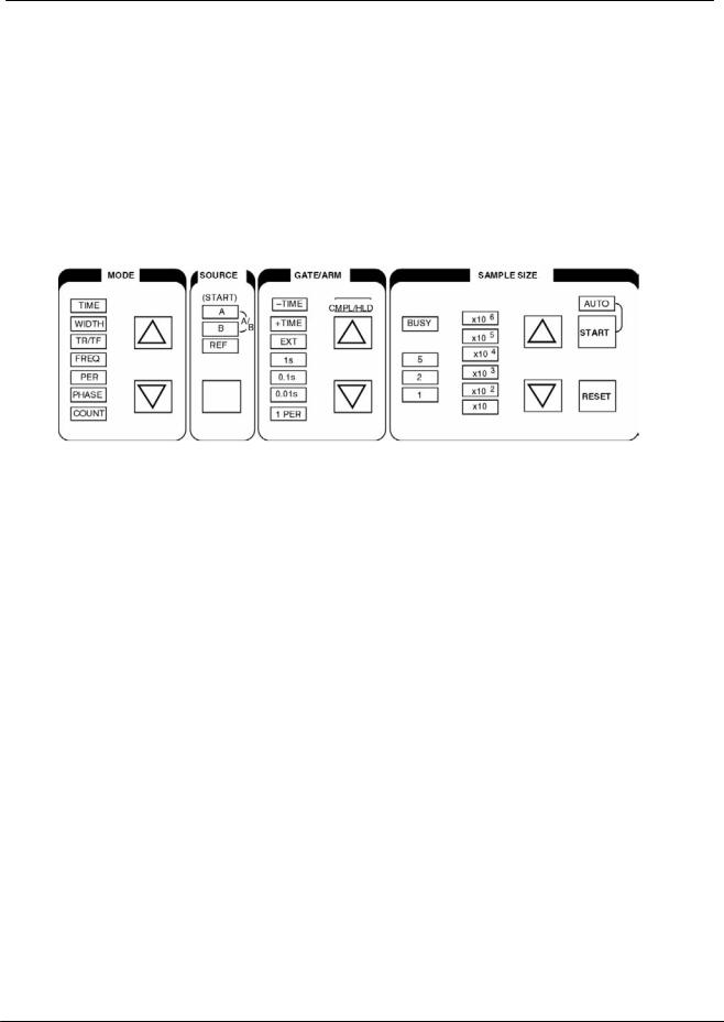
FRONT PANEL OPERATION
The SR620 Universal Time Interval Counter can perform an extremely wide variety of time interval and frequency measurements. The SR620 is designed so that the values of virtually all of the important measurement parameters are visible at a glance on the front panel. Setting the SR620 to perform a particular measurement can be separated into three steps: choosing the measurement, choosing the output display, and setting the inputs. The SR620 is different than most counters in that a "measurement" consists of from 1 to 1,000,000 "samples" and the SR620 reports statistical information on these samples. The SR620 can report the mean , jitter, maximum , and minimum values found in a measurement.
CHOOSING THE MEASUREMENT
SETTING THE MODE
Pressing the MODE up and down arrow keys sets the measurement type. The SR620 can measure time intervals, pulse widths, pulse rise and fall times, frequency, period, phase, and can count events. The ARMING section has detailed explanations of the modes.
SETTING THE SOURCE
The source key selects the signal source for a particular measurement. In time interval mode the source specifies which input will "start" the time interval. Normally the start source is channel A, but channel B, and the 1kHz REF output may also be selected. The other input then "stops" the time interval. In pulse width, frequency, period, and counts the source may be A, B, or the 1kHz REF. Additionally, in frequency, period, and count modes if both the A and B LEDs are on the RATIO A/B is measured. In rise/fall time mode only A and B may be the source, while in phase mode the phase of B relative to A is always measured.
SETTING THE ARMING MODE
"Arming" controls the conditions under which a sample is started and stopped. The arming mode is chosen using the ARMING up and down arrow keys. The SR620 has a large selection of arming
modes. The various modes relevant to each particular type of measurement are treated in detail in the ARMING section of this manual. A summary of the arming modes is given on the next page.
SELECTING THE NUMBER OF SAMPLES
The sample size up and down arrow keys select between 1 and 1,000,000 samples for the measurement.
STARTING AND STOPPING MEASUREMENTS
The "START" and "RESET" keys start and stop measurements. Press the "START" key to start a single measurement. The "BUSY" LED will remain on while the measurement is in progress. When the measurement is finished the SR620 will display the results and stop. Press and hold the START key to turn on the "AUTO" LED and "automeasure". When automeasure is on the SR620 will automatically start a new measurement when the present one is complete. Press the "RESET" key to terminate the present measurement. Press and hold the "RESET" key to turn the "AUTO" LED and automeasure off.
SR620 Universal Time Interval Counter

4 Front Panel Operation
SUMMARY OF ARMING MODES
mode |
arming mode |
LED indication |
time |
+TIME |
+TIME LED on |
|
+TIME EXTERNAL |
+TIME and EXT LEDs on * |
|
+TIME EXTERNAL STOP HOLDOFF |
+TIME, EXT, and HLDF LEDs on * |
|
±TIME |
± TIME LED on |
|
±TIME COMPLEMENT |
±TIME and CMPL LEDs on |
|
±TIME EXTERNAL |
±TIME and EXT LED on * |
width,rise/fall time |
+TIME |
+TIME LED on |
|
+TIME EXTERNAL |
+TIME and EXT LED on * |
|
+TIME EXTERNAL STOP HOLDOFF |
+ TIME, EXT, and HLDF LEDs on * |
frequency,period |
1 PERIOD |
1 PERIOD LED on |
|
0.01s gate |
0.01s LED on ** |
|
0.1s gate |
0.1s LED on ** |
|
1.0s gate |
1.0s LED on ** |
|
ext gate |
EXT LED on * |
|
ext 1 PERIOD |
EXT and 1 PERIOD LEDs on |
|
ext 0.01s gate |
EXT and 0.01s LEDs on ** |
|
ext 0.1s gate |
EXT and 0.1s LEDs on ** |
|
ext 1.0s gate |
EXT and 1.0s LEDs on ** |
phase |
+TIME |
+TIME LED on |
|
EXT |
EXT LED on * |
count |
0.01s gate |
0.01s LED on ** |
|
0.1s gate |
0.1s LED on ** |
|
1.0s gate |
1.0s LED on ** |
|
ext gate |
EXT LED on * |
|
ext 0.01s gate |
EXT and 0.01s LEDs on ** |
|
ext 0.1s gate |
EXT and 0.1s LEDs on ** |
|
ext 1.0s gate |
EXT and 1.0s LEDs on ** |
NOTES:
*arming delay or scanning delay/gate may be used in this mode (see CONFIGURATION MENU and ARMING sections). The EXT LED will flash if scanning is enabled.
**the gate time LED will flash if gate width multiplier is not equal to 1 (see CONFIGURATION MENU and ARMING sections).
SR620 Universal Time Interval Counter
Front Panel Operation 5
CHOOSING THE OUTPUT DISPLAY
The SR620 can display statistical information about the measurement of N samples. The SR620 computes and reports the mean, standard deviation or root Allan variance, minimum, and maximum values seen during the measurement. The equation for the statistical functions are given by:
SETTING THE FRONT PANEL DISPLAY
The DISPLAY up and down arrow keys control what is displayed on the 16 digit LED display. All of the statistical data is always calculated and may be viewed by scrolling through the displays. The settings are:
MEAN: displays the mean value of the measurement. If the display is prefaced by "r" then a relative reading is displayed and the value displayed is the mean minus the REL.
REL: displays the value of the REL. The REL is set by pressing the "SET" button and is cleared by
pressing the "CLR" button. Normally the REL is set to the value of the mean when the "SET" button is pressed. However, the REL may be set to an arbitrary value using the ZOOM feature described in the GRAPHICS ZOOM section below. Pressing the "CLR" button with the REL off clears the display.
JITTER: displays either the standard deviation (display prefaced by "d") or Allan variance ( display prefaced by "A"). The statistic that is used is set in the CONFIGURATION MENU.
MAX: displays the maximum sample found in this measurement. If the display is prefaced by "r" then a relative reading is displayed and the value displayed is the max minus the REL.
MIN: displays the minimum sample found in this measurement. If the display is prefaced by "r" then a relative reading is displayed and the value displayed is the min minus the REL.
TRIG: displays the trigger level set by the EXT, A, and B trigger knobs (The full scale range of the knobs may be set in the CONFIGURATION MENU.).
DVM: displays the voltage values at the rear panel DVM inputs.
Pressing both the up and down arrow keys together toggles the x1000 expand on and off in frequency and period mode. In frequency mode the x1000 expand moves the decimal point 3 places to the left and displays frequencies with nHz resolution. The maximum frequency measurable in this mode is 1 MHz. In period mode the x1000 expand moves the decimal point 3 places to the left and displays periods with fs
SR620 Universal Time Interval Counter

6 Front Panel Operation
resolution. The maximum period measurable in this mode is 1 s.
In both period and frequency modes the statistical data is displayed with the number of significant digits allowed by the SR620's resolution. Using longer gate times increases the resolution.
GRAPHICS OUTPUTS
In addition to the 16 digit LED display the SR620's scope and chart outputs may be used to give the user alternative methods of viewing the data.
SCOPE OUTPUTS
The SR620 may be attached to an oscilloscope operating in x-y mode to provide a graphical presentation of the output data. The oscilloscope should be set in x-y mode with sensitivities set to 1V/div and the SR620's x and y rear panel outputs attached.
GRAPH TYPES
The SR620 can then display either a histogram of number of samples vs. measured parameter for the samples within a measurement, a stripchart of mean values for successive measurements, or a stripchart of jitter values for successive measurements. In histogram mode a new graph will be displayed after each measurement of N samples is complete, showing the distribution of samples in that measurement. In the stripchart modes a new point will be added to the graph after each measurement indicating the mean and jitter values for that measurement. The display desired is chosen by pressing the select button below the indicator LEDs. The data for all three graphs are saved so that all of the graphs may be viewed by cycling through the three choices. The data, the scale values, and the cursor position are all displayed on the scope screen. In the stripchart modes up to 250 points will be displayed. When the display fills up new data will start to overwrite the old starting from the left. The graph may be cleared by pressing the CLR button below the PRINT button.
SCALING GRAPHS
In histogram mode the vertical scale, horizontal scale, and number of bins may be adjusted. In the stripchart modes the vertical scales may be adjusted. The easiest way to scale the graphs is to press the "AUTO" button to autoscale the graph. Autoscale will automatically adjust the scales so
that the data fits on the screen. In histogram mode the actual scaling of the graph does not occur until the next measurement is complete. The scale may also be adjusted manually. Pressing the up and down arrow keys with the normal display on the 16 digit LEDs will adjust the vertical scale on the displayed graph. In the histogram mode , incrementing the vertical scale past the largest value (200,000 / div) will change the vertical scale to a log scale. To view the scales on the LED display press the "DISP" button. First, the cursor position (discussed below) will be displayed. Pressing the button again will display the vertical graph scales in the appropriate units. In the histogram mode pressing the button again will display the horizontal scale and then the number of bins. The scales may be adjusted using the up and down arrow keys. When the REL is set the graphs are centered about the REL and, thus, very fine detail may be observed on a large number.
GRAPHICS CURSOR
The displayed graphs have a moveable cursor that allows one to read the values of individual points on the screen. The cursor is represented on screen by a dotted line. The cursor is moved by pressing the "DISP" button to display the cursor position and using the up and down arrow keys to move it about. The cursor x position is displayed on the LED display ( in the correct units of s, Hz, etc.) for the histogram display and measurement number for the stripcharts. Both the x and y positions are displayed on the scope screen.
GRAPHICS ZOOM
The SR620 has a feature which allows one to zoom in on any feature in a displayed histogram, this feature also allows the REL to be set to any value desired. First, press the DISP button to display the cursor position. Then, move the cursor until it is at the desired position ( or the cursor value is the desired REL value if setting the REL). Push the "SET" button. This will set the REL to the cursor position. Now, adjust the graph horizontal scale to get the magnification desired. If setting the REL value, note that the amount that the cursor value changes for each press of the arrow keys is determined by the horizontal histogram scale and that the scale may have to be adjusted to get the REL value desired.
SR620 Universal Time Interval Counter
Front Panel Operation 7
HARDCOPY OUTPUT
The displayed graph may be copied to either an Epson compatible graphics printer or a HP-GL compatible plotter by pressing the "PRINT" key. The SR620 will continue to take data while the hardcopy is being generated. If a second print/plot request is made (by pressing the button or a programming command) before the current copy is finished the SR620 will stop taking data until the current copy is done. This is to avoid corrupting the second copy as the SR620 only has a 1 deep graphics output queue.The output device (printer or plotter) is chosen in the CONFIGURATION menu (see that section for detail). When using a printer the SR620 may be put into autoprint mode by pressing and holding the PRINT key until the "AUTO" LED turns on. In autoprint mode the SR620 will automatically print every histogram or a new stripchart each time the stripchart fills up. There is no autoprint when using a plotter because the paper needs to be changed. In autoprint mode the speed of the printer may determine the measurement rate if new graphs are generated
faster than the printer can print them. A print or plot may be aborted by pressing the "CLR" button under the PRINT button. Pressing and holding the CLR button will turn off autoprint. If the message "print error" or "plot error" appears while printing or plotting please refer to the TROUBLESHOOTING section.
CHART OUTPUTS
In addition to the scope outputs the SR620 also has two rear panel analog outputs designed to go to analog chart recorders. One output puts out a voltage proportional to the mean of the measurement while the other output puts out a voltage proportional the jitter of the measurement. The output range is 0-8V corresponding to the 8 vertical scope divisions. The scale is the same as the scope scales. In the cases where zero is at the center of the scope screen (the REL is set, for example) zero will correspond to 4 volts output. The chart outputs may also be configured as general purpose D/A outputs (see CONFIGURATION MENU section).
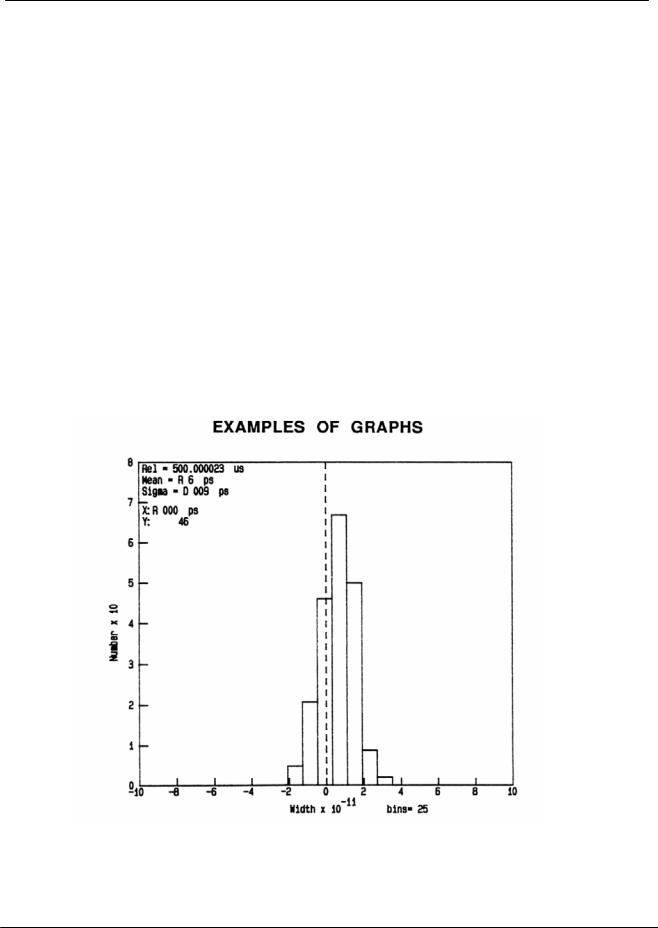
Sample Histogram. The graph scales are 20ps/div in the horizontal direction and 10 /div in the vertical. The REL is 500.000023 us and is at the center of the graph. This measurement has a mean value 6ps greater than the REL and a standard deviation of 9ps. The cursor (dotted line) is at the REL and there are 46 events in that bin.
SR620 Universal Time Interval Counter
8 Front Panel Operation
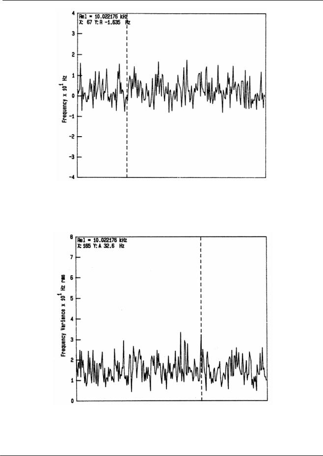
Sample mean value graph. Each point corresponds to the mean value from one measurement. The vertical scale is 10 Hz/div. The measurements are relative to a REL of 10.022176 kHz. The REL is at the center of the graph. The cursor (dotted line) shows that measurement number 67 was 1.635 kHz below the REL.
Sample jitter stripchart. This graph shows the jitter associated with each measurement above. The vertical scale is 10 Hz/div. The cursor is at measurement number 165 and the jitter value there is 32.6 Hz.
SR620 Universal Time Interval Counter
Front Panel Operation 9
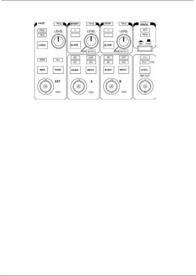
SETTING THE INPUTS
SETTING TRIGGER LEVELS
The trigger levels are set by rotating the trigger level adjust knobs. These knobs may have a full scale range of ±5.00V, ±2.50V, or ±1.25V. The full scale range is set in the CONFIGURATION menu (see that section of the manual for details). In all cases the trigger level resolution is 10mV and the actual level may be displayed on the front panel. The trigger inputs have about 40mV of hysteresis and the trigger levels are corrected for this hysteresis so that the inputs will trigger at the selected voltage independent of the selected trigger slope.
The LED's above the trigger knobs will flash when the input comparator triggers. The A and B inputs may also be set to autolevel by rotating the knobs completely counter-clockwise. The "AUTO" LED under the knob will come on and the trigger threshold will automatically be set to the midpoint of the signal. Autolevel will work for a signal faster than about 10Hz and a duty cycle greater than about 0.0001%. The autolevel circuit will not change the trigger level until the input stops triggering for more than 1/2 second. Then it will try to reset the trigger level to a new value. The red LEDs behind the words "START" and "STOP" will flash each time the autolevel circuit tries to adjust the trigger threshold.
NOTE: in width and rise/fall time modes, which use only one input, the A trigger knob sets the start trigger voltage and the B trigger knob sets the stop trigger voltage.
SETTING TRIGGER SLOPES
The A and B inputs can be set to trigger on either a rising or falling edge by pressing the "SLOPE" buttons. The EXT input can be set to rising edge or falling edge by pressing the "LOGIC" button. If the EXT input is being used to supply a gate pulse the SR620 will use the time above threshold as the gate if POSitive logic is selected and the time below threshold as the gate if NEGative logic is selected.
INPUT TERMINATION
The EXT, A, and B input may all be terminated in either 1MOhm or 50 Ohms by pressing the "INPUT" or "TERM" buttons. If the inputs are terminated in 50 ohms and the input signal exceeds ±6V peak the 50 Ohm terminator will automatically be removed to prevent damage to the terminator. When this overload condition occurs the 50 ohm LED will flash.
UHF PRESCALERS
In frequency and period modes the input signal may be fed to the SR620's UHF prescalers to measure signals between 40MHz and 1.3GHz. To engage the prescalers press the "INPUT" button for the desired channel repeatedly until the UHF LED comes on. The sensitivity of the prescalers may be adjusted by adjusting the channel A and B trigger knobs. Setting the knobs for 0V or to autolevel will set the sensitivity to maximum. Setting the knobs to 5V will reduce the sensitivity
SR620 Universal Time Interval Counter

10 Front Panel Operation
to about 200mV rms. Both positive and negative settings of the knob have the same effect. The sensitivity adjustment is useful because at maximum sensitivity the prescalers will selfoscillate with no signal input. With an input, however, this is not a problem, but by reducing the sensitivity slightly these oscillations will disappear.
INPUT COUPLING
The A and B inputs may be either AC or DC coupled by pressing the AC/DC button. The coupling is independent of the input termination impedance. The EXT input is always DC coupled.
REFERENCE OUTPUT
The front panel REF output puts out a 1kHz 50% duty cycle square wave synchronized to the SR620's internal 10MHz clock. This output may provide 4V into high impedance or 2V into 50 Ohms, or ECL levels into 50 Ohms. An example of the use of this output is to set the mode to measure the time from REF to B. If a cable is then connected from the REF output to B the cable delay may be directly measured.
TIMEBASE INPUT AND OUTPUT
A rear panel BNC outputs the SR620's 10MHz clock. This output supplies approximately 1V pkpk into a 50 ohm load. Another BNC allows the input of a 5 or 10 MHz external timebase. This input presents a 1 kOhm load to the signal. The SR620 can then phase-lock its internal timebase to this external source. See the CONFIGURATION MENU chapter for detail on using an external timebase.
DVM INPUTS
The SR620 has two rear panel DVM inputs. These 1 MOhm differential inputs allow the SR620 to measure DC voltages on either a 2V or 20V full scale range. The SR620 can either autorange the inputs (default) or they may be set to a fixed scale. See the CONFIGURATION MENU chapter for detail on setting the DVM scales.
SR620 Universal Time Interval Counter
Sample Arming 11
SAMPLE ARMING
The SR620 Time Interval counter has a wide variety of arming modes that allow the user great flexibility in controlling the desired measurement. The various measurement modes and their respective arming modes are discussed in detail below.
NOTE: references to delayed or scanning gates are discussed at the end of this section
TIME MODE
In this mode, the unit measures the time interval between a Start and a Stop pulse. The time interval is a positive number if the Start occurs before the Stop and negative if the Stop occurs before the Start. The SOURCE LED's indicate the source of the START pulse.
Source LED |
Start Source |
Stop Source |
A |
A |
B |
B |
B |
A |
REF |
REF |
B |
(The knobs which are directly above each input set the voltage threshold for that input when in the TIME mode.)
Usually, A will be selected as the Start source and the time interval from A to B will be measured. The internal 1kHz REF output may be selected in cases where the front panel REF out will be used to trigger an event, and the "event" will provide a Stop pulse to the B input. A simple example of this would be the measurement of cable lengths. The length of a cable may be measured by selecting REF as the Start source, and connecting the cable between the REF output and the B input.
When REF is used as the Start source, the rising edge of REF is used when a positive slope is selected for the A input, and the falling edge is used when a negative slope is set. In this case, the threshold knob above the A input has no effect on operation.
TIME INTERVAL ARMING
There are several arming modes for Time interval measurements. The arming mode controls when the instrument will be ready to take a sample. Start and Stop pulses are ignored when the instrument is not armed. The ARM LED will turn on when the unit is armed. The SR620 remains busy for about 800us after receiving a Start/Stop pair and may not be rearmed during this time.
+TIME MEASUREMENTS (-1ns to 1000s)
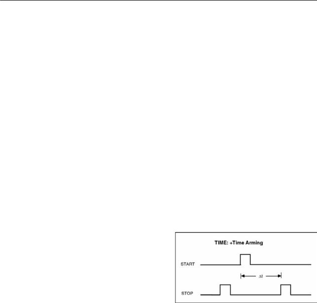
In +TIME arming the Start input is armed as soon as the instrument is ready and Stop is armed when a Start is received. In this mode only a positive or zero time interval may be measured.
In +TIME EXTERNAL mode the Start input is enabled by the GATE and Stop is armed by Start. A delay from an EXT input may be set or scanned in the CONFIG menu, otherwise the EXT input will be the trigger.
|
Time Arming Mode |
Function |
|
|
+TIME |
Start arms automatically, Stop is armed by Start |
|
|
+TIME EXTERNAL |
Start is armed by EXT input, Stop armed by Start |
|
|
+TIME EXTERNAL STOP HOLDOFF |
Start is armed by leading edge of EXT input and the Stop is |
|
|
|
armed by the trailing edge. |
|
|
±TIME |
Starts and Stops are armed by Start/Stop pair |
|
|
±TIME COMPLEMENT |
Starts and Stops are armed by Stop/Start pair |
|
|
±TIME EXTERNAL |
Starts and Stops are armed by EXT input |
|
|
|
|
|
|
|
|
|
SR620 Universal Time Interval Counter

12 Sample Arming
TIME EXTERNAL with HOLDOFF is similar except that Stops are not enabled until the trailing edge of the EXT input. A particular Stop pulse may be selected to end the time interval by using the EXT input to inhibit, or holdoff, the Stop input. An example of this might be measuring the time from the index mark on a hard disk drive to a particular data bit. By adjusting the holdoff time one could measure the time to any data bit instead of just the first one.
The trigger may be delayed or scanned from an EXT trigger input by setting SCAN parameters in the CONFIG menu. A blinking EXT LED indicates that the EXT is used as a trigger for the delayed gate.
±TIME MEASUREMENTS (-1000s<t< 1000s)
In all of the ± TIME modes Starts and Stops are armed simultaneously and so either a positive or negative time interval may be measured. There is, unfortunately, some ambiguity to this method of arming. For periodic inputs there is no way for the instrument to know if the desired time interval should be measured from the Start to the previous Stop or to the next Stop. For example, if the Start
and Stop are both 1 KHz square waves, with the Stop edge following the Start edge by 1 uS, then the unit will report a Time interval of either +1 us or -999 us. In the ±TIME and ±TIME COMPLEMENT modes the start and stop inputs are armed by parity, that is, the reception of either a Start/Stop pair or a Stop/Start pair of pulses. By changing between these two modes one may choose to measure either the time from Stop to the next Start or Start to the next Stop. Since the parity of the input signals is randomly determined at power-up there is no way to specify which arming mode will correspond to which measurement. But by changing between these modes both measurements may always be obtained.
Alternately, one may arm a ±Time measurement with a signal applied to the Ext input in which case the measurement that is made (Start to Stop or Stop to Start) is determined only by the relationship of the Ext input to the Start and Stop signals.
The EXT input requires about 10 ns setup prior to the Start or Stop inputs.
Time intervals as a function of delay from an EXT trigger may be measured by using the internal delay generator. The delay generator is triggered by the EXT input. The trigger delay may be set or scanned via the CONFIG Menu.
SR620 Universal Time Interval Counter
Sample Arming 13
Time interval samples may also be armed by pressing the MAN key when in the EXT arming mode.
WIDTH
Pulse widths may be measured in the WIDTH mode. The pulse source may be either the A input, the B input, or the internal 1 kHz REF source.
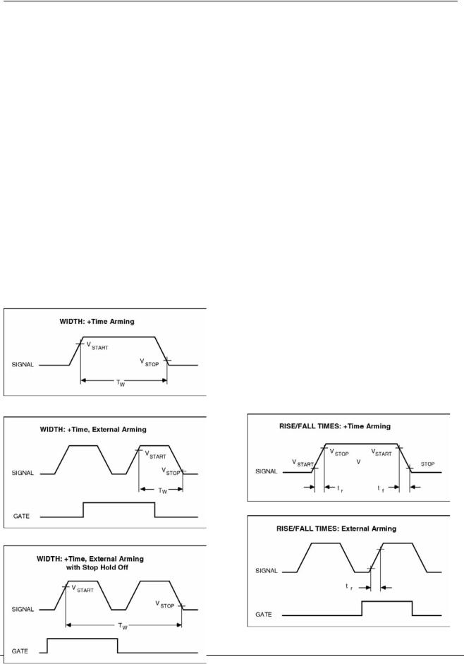
The Start threshold and slope are set by the controls just above the A input. The Stop threshold and slope are set by the controls just above the B input. If the Start slope is positive, the Stop slope will be negative, and the time from a rising edge to a falling edge will be measured. These controls are not used when measuring the width of the internal 1 KHz REF.
As pulse widths are always positive times, only the +TIME arming modes are available. The three arming modes for WIDTH measurements are shown here. The trigger source may be either the EXT input or the EXT triggered internally delayed/scanned gate.
RISE and FALL TIMES
The transition time for an input may be measured in this mode. Either the A or B input may be selected as the source to be measured. The selected source is used as the input to both comparators. The threshold knob above the A input is used to specify the Start voltage threshold, and the knob above the B input is used to specify the Stop voltage threshold. The rise time of the input is reported if positive slope is selected, and the fall time is reported if negative slope is selected. Either slope key changes both comparators' slope LED's.
For example, to measure the 20-80% rise time of a one volt input, the A threshold would be set to 0.20 VDC, the B threshold would be set to 0.80 VDC, and the slope would be set to positive to measure the rising edge. The 80-20% transition time of the falling edge could be measured by setting the slope to negative and adjusting the trigger thresholds. Reported times are not corrected for the finite bandwidth of the input of the instrument. The inputs have a bandwidth of about 300 MHz, and so the 10-90% transition time of an infinitely fast input would be reported as 1.2 ns. When measuring 10-90% transition times, the actual transition time may be found by:
T actual = sqrt (T measured2 - 1.2 ns2 )
As transition times are always positive numbers, only +TIME and +TIME_EXT arming modes are allowed.
SR620 Universal Time Interval Counter
14 Sample Arming
FREQUENCY
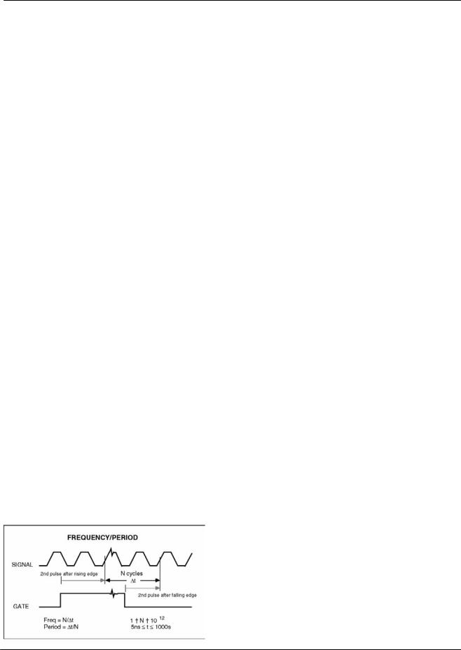
The frequency of either the A or B inputs may be measured in this mode of operation. The SR620 is a "reciprocal" frequency counter. That is, it measures frequency by measuring the time interval for an integer number of cycles of the input. The frequency is then equal to (number of cycles)/(Measured Time). Since there is no fraction-of-a-cycle error ( as would be seen if the unit merely counted cycles in a fixed gate ) a frequency measurement can be made to 11 digits of resolution in one second. For frequencies between 0 and 200MHz the SR620's front end comparators may be directly used. For frequencies between 200MHz and 1.3GHz the Ultra High Frequency (UHF) prescalers must be used.
The number of cycles used in the sample is determined by the GATE . The instrument will always measure at least 1 period of the input. Gates from 1ms to 500s, or EXTernal gates may be selected from the front panel. The actual gate time for the internal gates is the gate time set on the front panel multiplied by the "gate scale" set in the configuration menu. Thus if one desired a 20s gate one would set the gate scale to 200 and the gate time to 0.1s (0.1s x 200 = 20s). If the "gate scale" is not set to the default of 1 the gate time led on the front panel will blink. Due to internal synchronization circuitry, the frequency measurement starts on the 2nd input edge after the gate opens and ends on the second input edge after the gate closes. Thus, a frequency measurement always requires at least 2 complete cycles of the input waveform.
The choice of GATE mode is determined mainly by the desired resolution and measurement speed. A longer gate results in a higher resolution measurement with 11 digits obtainable in a one second sample. The SR620 always adjusts the number of displayed digits to reflect the appropriate resolution depending on gate time. The accuracy of frequency measurements is
determined by the accuracy of time interval measurements. For very short gates, the accuracy is determined by the 200ps time interval accuracy, while for long gates the accuracy is limited by the accuracy of the timebase.
EXTERNAL gates may be applied to the EXT input and may range from 5ns to 1000s, although the SR620 always measures for at least 1 input period regardless of the gate time. The setup time for an external gate is about 10 ns. Additionally, the EXT input may be used to trigger any of the internal gates (in this mode both the "ext" and the gate time LED will be on). This is useful , for example, to synchronize a 0.1s gate to an external event. Additionally, gates of 1 us to 10 ms may be scanned using the SR620's scanning facility. These gates must be externally triggered. The gate may either be fixed in time relative to the EXT input, or may be automatically scanned at the end of a measurement of N samples. If scanned, the step size is equal to the gate width and the initial delay may be set between 1 and 50000 gates times. This scanning ability allows one to make measurements of frequency as a function of time from some event, such as the time response of a VCO to a step change in control voltage.
The RATIO of the frequencies of two inputs will be displayed if both the A & B source LED are on. It should be noted that the A and B frequencies are not measured simultaneously but are measured on alternate measurement cycles.
PERIOD
Period measurements are done virtually the same way as frequency measurements, however the reciprocal of the frequency is reported instead of the frequency. Gating modes are identical to those used in the frequency mode.
When both the A and B source lights are on, the ratio of the periods of signals applied to the A and B inputs may be displayed. Period ratios may span from 10-9 to 10+3.
PHASE
The phase between the A and B inputs is measured in this mode of operation. Two measurements are actually being done: the period of the A input and the time interval between the A and B inputs. For example, suppose the A and B inputs are both 1 KHz square waves (1000us period) with the rising edge of B coming 250us after the rising edge of A. The unit would measure
SR620 Universal Time Interval Counter
 Loading...