


Model SR630
16 Channel Thermocouple Reader
Thermocouple Reader
1290-D Reamwood Avenue
Sunnyvale, CA 94089 U.S.A.
Phone: (408) 744-9040 • Fax: (408) 744-9049
Email: info@thinkSRS.com • www.thinkSRS.com
Copyright © 1992, 1994, 1995, 1997
Stanford Research Systems, Inc.
All Rights Reserved
Revision 1.3 (09/2001)
1

2
Model SR630

Specifications 4
Preparations for Use 5
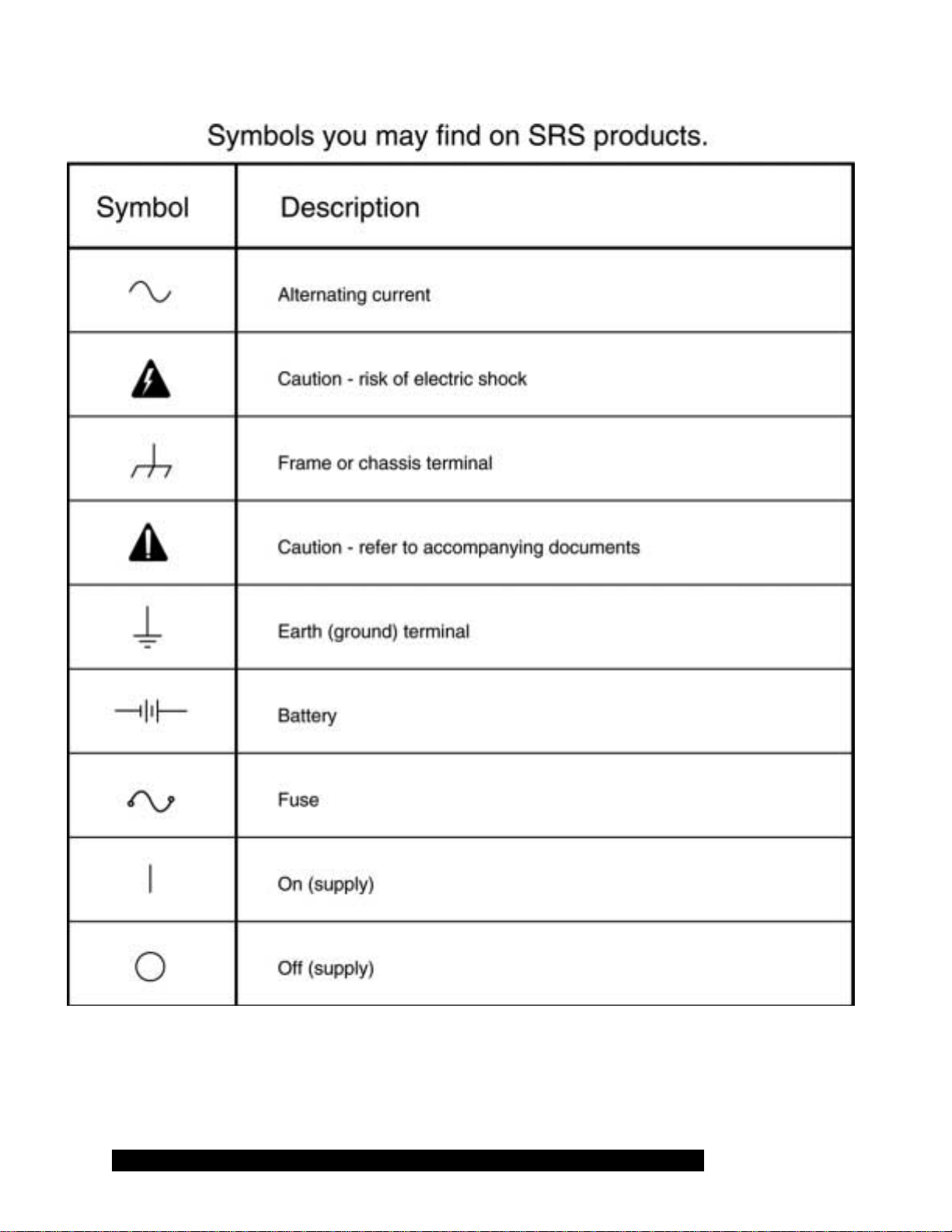
Symbols 6
Quick Start Instructions 7
Instrument Overview 8
Front Panel Description 9
Rear Panel Description 11
Operation 12
Connecting Thermocouples 12
Setting Instrument Parameters 12
(GPIB Address, RS232 Baud Rate,
Time and Date, Printer Mode,
and Scan Dwell Time/Logging Mode)
Setting Channel Parameters 13
(Measurement Units, Scan Enable,
TC Type, Nominal Temperature,
Temperature Deviation, Chart Span
Alarm Enable, Alarm Relay, and
Temperature Limits)
Troubleshooting and error messages 15
Table of Contents
Computer Interfaces 16
Command List 17
Programming Examples 22
Thermocouple Reference Data 26
Characteristics of Thermocouple Types 27
Calibration 29
Voltmeter Input Offsets 30
Voltmeter Gain Factors 30
Zone Block Temperature Offsets 30
Channel Temperature Offsets 31
Analog Output Gain Factors 31
Circuit Description 33
Microprocessor System 33
Display Drivers 33
Analog Outputs and Block Temperature 34
Time and Date 35
Relay Multiplexers 35
Input Amplifiers and ADC 35
Power Supplies 36
Computer Interfaces 36
Front Panel Display 37
Component Parts List 38
Circuit Schematic Diagrams 51
Thermocouple Reader
3

Specifications
Voltmeter Specifications
Channels 16
Input Type Independent, floating, and differential.
Input Resistance 10 MOhms between + & -, >1 GOhm to ground.
Input Capacitance .001 uF
Input Bias Current <100 pA
Input Protection 250 Vrms
Full Scale Display ±9.999, ±99.99, ±999.9 mVdc
±9.999, ±99.99 Vdc
Range Select Automatic
Resolution ±1 of least significant displayed digit.
Offset ±2 of least significant displayed digit.
Gain Accuracy 0.05%
Conversion Rate 10 Hz for 50 Hz line, 12 Hz for 60 Hz line.
Line Rejection >100:1
Thermocouple Specifications
(Input Specifications are same as the Voltmeter Specifications)
Channels 16
Thermocouple Types B, E, J, K, R, S, T
Display Units Degrees C, F and K
Display Resolution 0.1 Degree C
Temperature Displays Actual, Nominal, or Offset
Open Check Current 250 uA
Accuracy 0.5 Deg C for J, K, E, and T
1.0 Deg C for R, S, and B
(Errors are for the SR630 only. Standard errors for thermocouple
wire are 2 to 5 times the error due to the SR630. See section on
thermocouple reference data for additional information.)
Scanning and Data Logging Functions
Dwell Time 10 to 9999 seconds between successive scans.
Alarm Temperature or voltage limit for each channel.
Alarm Relay Rated for up to 1 amp and 100V DC/AC, 30W/60VA
maximum (resistive load).
Scan Enable Channel may be scanned or skipped.
Proportional Outputs For Channels 1, 2, 3 and 4, ±10V.
Printer Output Voltages, Temperatures, Time and Date
as a list or in a graphical format.
Data Memory Last 2048 measurements in battery
backed-up memory.
General
Store and Recall Nine locations for instrument set-up.
Interfaces RS232, GPIB, and Centronics Printer (Standard)
All instrument functions controllable via RS232 or GPIB.
Power 100/120/220/240 Vac, 50/60 Hz.
Rack Mount Optional
Dimensions 8.5" x 3.5" x 13" ( W x H x D )
Weight 9 lb.
4
Model SR630

(All specifications apply for 18° C to 28° C operation.)
**********CAUTION**********
Preparation for Use
This instrument may be damaged if operated with
the LINE VOLTAGE SELECTOR card set for the
wrong ac line voltage or if the wrong fuse is
installed.
Line Voltage
The SR630 can operate from a 100 V, 120 V,
220 V or 240 V ac power source having a line
frequency of 50 or 60 Hz. Before connecting the
power cord to a power source, verify that the LINE
VOLTAGE SELECTOR card, located in the rearpanel fuse holder of the unit, is set so that the
correct ac input voltage value is visible.
Conversion from one ac input voltage to another
requires a change in the fuse holder's LINE
VOLTAGE SELECTOR card position and a new
fuse. Disconnect the power cord, slide the fuse
holder cover to the left and rotate the fuse-pull
lever to remove the fuse. Remove the small printed
circuit board. Select the operating voltage by
orienting the printed circuit board. Press the circuit
board firmly into its slot, so the desired voltage is
visible. Rotate the fuse-pull lever back into its
normal position and insert the correct fuse into the
fuse holder.
electrical shock, always use a power source outlet
that has a properly grounded protective-ground
contact.
Power-Up
All instrument settings are stored in nonvolatile
memory (RAM backed-up) and are retained when
the power is turned off. They are not affected by
the removal of the line cord. If the power-on self
test passes, the unit will return to the settings in
effect when the power was last turned off. If an
error is detected, or if the backup battery is
exhausted, default settings will be used.
Use in Biomedical Applicat ions
Under certain conditions, the SR630 may prove to
be unsafe for applications involving human subjects.
Incorrect grounding, component failure, and
excessive common-mode input voltages are
examples of conditions in which the instrument may
expose the subject to large input currents.
Therefore, Stanford Research Systems does not
recommend the SR630 for such applications.
Furnished Accessories
Line Fuse
Verify that the correct line fuse is installed before
connecting the line cord to the unit. For 100 V and
120 V, use a 1/2 Amp fuse and for 220 V and 240
V, use a 1/4 Amp fuse.
Line Cord
The SR630 has a detachable, three-wire power
cord with a three-contact plug for connection to
both the power source and protective ground. The
protective ground connects to the accessible metal
parts of the instrument to ground. To prevent
Thermocouple Reader
- Power cord
- Operating manual
Environmental Conditions
OPERATING
Temperature: +10° C to +40° C
(Specifications apply over +18° C to +28° C)
Relative Humidity: < 90% Non-condensing
NON-OPERATING
Temperature: -25° C to +65° C
Humidity: < 95% Non-condensing
5
6
Model SR630

1. Remove the rear cover thermal shield and
attach a K-type (Chromel-Alumel) thermocouple to
channel #1's input on the rear panel. (One such
thermocouple has been provided with the unit.) The
red lead should be connected to the negative (-)
input and the yellow lead to the positive (+) input.
(These are US color codes.) Replace the thermal
shield.
2. Verify that the power entry module on the rear
panel is set for the voltage in your area. Using a
three wire power cord, connect the unit to line
power.
3. Press the POWER button to turn the unit 'ON'.
Use the CHANNEL SELECT keys to select channel
#1. Use the PARAMETER SELECT keys to select
'UNITS' from the parameter list. Select centigrade
scale by pressing the number '7' on the
PARAMETER ENTRY key pad. Then select 'TC
TYPE' from the parameter list, and set the
thermocouple type to K by pressing the number '3'.
Quick Start Instructions
4. The temperature, in degrees centigrade,
should be displayed in the MEASUREMENT
window. Warming the thermocouple with your
fingers should cause the temperature to rise: if the
reported temperature goes down, then the
thermocouple was probably attached with the
wrong polarity. (Remember, the red lead is
negative for the US, positive for European
standards.) Type K thermocouples have a standard
limit of error of ±2.2 °C. Type K thermocouples
supplied by SRS have special limits of error of
±1.1°C.
Thermocouple Reader
7

Instrument Description
Figure 1. SR630 Thermocouple Reader
Instrument Overview
The Model SR630 is a 16 Channel "computing"
microvoltmeter. The unit can digitize 16 rear panel
differential inputs with a resolution of 15 bits plus
sign. Gains and offsets are controlled to microvolt
levels. The dual slope integrating converter is
synchronized to the line frequency for high noise
immunity. The unit completes 10/12 conversions
per second when used on a 50/60 Hz line.
The unit determines the temperature of a
thermocouple junction by measuring the voltage
and computing the temperature from the known
characteristics of B, E, J, K, R, S or T type
thermocouples. Additional junctions are formed
where the thermocouples connect to the back
panel of the instrument, but the SR630
compensates for these by measuring the
temperature of the connector block and subtracting
the expected voltages (which depend on the
thermocouple type and connector block
temperature) before computing the thermocouple
temperature.
Four analog outputs on the rear panel of the
instrument may be used to drive strip chart
recorders or to adjust proportional temperature
controllers. Small offset voltages at the outputs
may be nulled from the front panel or via the
computer interfaces.
The SR630 has GPIB (IEEE-488), RS232 and
printer interfaces. The GPIB and RS232 may be
used to control all functions and to read data from
the instrument. The printer port may be used to log
data from the 16 channels in either a numerical or
graphic format.
An alarm may be set to signal when the measured
temperature goes above Tmax or below Tmin or if
the thermocouple becomes an open circuit. A rear
panel BNC provides a switch closure during an
alarm condition or when the unit is turned off.
A battery-backed-up real-time clock maintains the
time and date when the unit is off. An alarm may
be set to signal when the meausred temperature
goes above Tmax or below Tmin or if the
thermocouple becomes an open circuit. A rear
panel BNC provides a switch closure when there is
an alarm condition, or when the unit is turned
“OFF”.
8
Model SR630

Front Panel De sc r i pti on
Displays
The front panel has three display windows.
Generally, the left display indicates the selected
channel, the middle display an instrument or
channel parameter value (e.g. GPIB address or
temperature alarm limits), and the right display the
measured value (in the appropriate units).
Channel Select and Scanning Mode
The CHANNEL up/down buttons select one of
sixteen rear panel inputs. Pressing the up and
down buttons simultaneously causes the instrument
to begin scanning selected channels (A channel is
selected by setting its SCAN ENABLE parameter
to “yes”). In scan mode, the SCANNING LED will
be lit and selected channels will be read as rapidly
as possible, beginning with the lowest channel
number. If a printer is hooked up, scan data will be
printed (in either List or Graph mode) at the end of
the run. The DWELL TIME (10 to 9999 seconds)
sets the time between the start of subsequent
scans.
The rear panel analog outputs will be updated only
when the corresponding channel is scanned or
displayed manually. Printer activity stops when
scanning is stopped.
Parameter Select
PARAMETERs are selected for display and
modification using the parameter up/down keys.
These parameters are listed in Table 1. The first
six are "instrument parameters" which may be
modified regardless of the selected channel; the
rest are channel specific.
Store and Recall
Store (STO) and Recall (RCL) keys are used to
save and retrieve parameter settings for all
channels (not just a selected channel). There are
nine storage locations (1-9) and ten possible recall
locations(0-9). To store/recall location 7 press
STO/RCL 7 EXC. Recalling location 0 will set the
instrument to its default state.
Name Description
Instrument: GPIB ADD GPIB interface address, 1-31
RS232 BAUD RS232 baud rate, 150, 300, ... 9600 baud
DATE Month.Day.Year (US Format) Ex: 12/31/1999
TIME Hours.Minutes Seconds(24 Hour Format) Ex: 23:59:00
PRINTER Off, List, grph ( Off, list or graphics )
DWELL Time between start of scans, and buffer mode (stop/roll)
Each Channel: UNITS Select Degrees K, C, F, mVdc, or Vdc
SCAN ENABLE Select Yes or No for inclusion in scan list
TC TYPE Thermocouple type B, E, J, K, R, S, or T
Tnom Nominal temperature for this channel and chart center
∆T=T-Tnom Measured deviation from nominal temperature
CHART SPAN Range of values for strip charts and analog outputs
ALARM ENABLE Enable alarm if temperature exceeds limits
Tmax Upper limit before alarm
Tmin Lower limit before alarm
Table 1. List of instr ument and Channel Parameters
Thermocouple Reader
9

Front Panel De sc r i pti on
Channel: Display channel 1, not scanning.
Parameter: Display GPIB address. Set
parameters as follows:
GPIB ADD Not affected
RS232 BAUD Not affected
DATE Not affected
TIME Not affected
PRINTER Off
DWELL 10 s
key is pressed. The backspace key (BKSP) may
be used to delete a key press or to return to the
previous value if all of the new key presses are
deleted.
If the UNITS for a channel are changed, then
Tnom, CHART SPAN, Tmax and Tmin will be
calculated to replace the existing values. This
allows the user to change units without affecting
the operation of the alarms or analog outputs. The
relative temperature display will be in the new
units.
UNITS Deg C
SCAN ENABLE Yes
TC TYPE K
T NOM 0
CHART SPAN 1000
ALARM ENABLE Yes for 1 to 4
Tmax 1000
Tmin 0
Table 2. Instr ument Default St at e ( after RCL 0)
Parameter Entry
Parameters may be entered using the 15-button
keypad. If the instrument is in the GPIB REMOTE
mode, press the execute (EXC) key first to return
to LOCAL operation. Numeric parameters (e.g.
GPIB address or nominal temperatures ) may be
entered directly, while non-numeric ones (e.g.
printer mode and display units) are selected by
pressing the key directly below the desired legend.
The PARAMETER display indicates non-numeric
data as follows:
PRINTER oFF LISt grPh
UNITS AbS CEnt FrEn dC
SCAN EN yES no
The TEMP key provides a convenient way to enter
the present temperature for Tnom.
The MEASUREMENT Display will be formatted for
-999.9 to 9999. degrees or ±9.999 mV, ±99.99
mV, ±999.9 mV, ±9.999 V, or ±99.99 V. Minus
signs are displayed but plus signs are omitted on
all displays. Selected units for each channel are
indicated on the units indicators just to the right of
the display.
Status Indicators
Status indicators are located above the power
switch. These LEDs indicate the various conditions
detailed in Table 3.
REMOTE GPIB Remote state. (Press EXC
to go to LOCAL.)
GPIB Turns on for any GPIB activity,
and stays on until end-of-record.
RS232 Turns on for any RS232 activity,
and stays on until end-of-record.
PRINTER Turns on when data sent to
printer.
ERROR Red LED for command, parameter
or printer errors.
The entered parameter becomes valid when the
EXC key is pressed or when a parameter up/down
10
Table 3. St at us Indicators
Model SR630

Rear Panel Description
Figure 2. SR630 Rear Panel
The rear panel of the instrument is shown in Figure
2. The thermal shield has been removed by
unscrewing the thumbscrews on either end of the
shield. The printer port, GPIB (IEEE-488
compatible) and RS232 interfaces are located
along the top. All control functions and parameter
settings may be set via the GPIB or RS232
interfaces.
The RS232 port is type DCE and may be attached
directly to PCs by using a standard (i.e. not "nullmodem") serial cable. The RS232 baud rate may
be set from the front panel to any standard speed
from 150 to 9600 baud.
A Centronics compatible printer may be attached
(for data logging) by using a standard "PC" parallel
cable. The printer interface supports two print
modes: LIST mode which lists the time, date and
temperatures (or voltages) for all channels
selected to be scanned, and a graphics mode,
which prints a strip chart recording of the selected
channels, with a new line printed every Dwell
Time. A line of text which details all instrument
settings is printed whenever a print mode is
selected.
Four rear panel analog outputs provide dc outputs
in the range of ±10.0 Vdc. These outputs may be
set to track the difference between the nominal and
measured temperatures (or voltages) of the
corresponding channel (1 t hrough 4) f or
proportional temperature control or analog strip
chart recording. The analog voltage at these rear
panel outputs is given by:
Vout = 20 * ( T - Tnom ) / Chart Span
If the output voltage is used to control a heater to
maintain an object above ambient temperature, the
user should enter a negative chart span so that the
output voltage will decrease (reducing heater
power) as the measured temperature increases.
If desired, the analog outputs may also be
configured (via remote programming) as simple
voltage sources in the range +/- 10V.
The 16 differential inputs to the SR630 are also
located on the rear panel. Each input floats with
respect to chassis ground and has a 10 MΩ
resistance between the + and - terminals.
Thermocouple Reader
11

Instrument Opera tion
Connecting Thermocouples
Thermocouples may be connected to the
instrument by removing the thermal shield on the
rear panel. This shield is important for accurate
temperature measurements and should be
replaced after the thermocouples are attached.
Type B, E, J, K, R, S or T thermocouples may be
used. The thermocouple type must be specified for
each channel, either by front panel entry, or via one
of the computer interfaces.
Setting Instrument Parameters
Six parameters affect the entire instrument while
eight are channel-dependent. Instrument
parameters are GPIB address, RS232 baud rate,
printer mode, dwell time, logging mode, time and
date. Channel parameters are units (volts or
temperature), scan enable, thermocouple type,
nominal temperature (or voltage), chart span,
alarm enable and alarm limits (max,min).
Parameters are selected with the PARAMETER
SELECT up/down keys. Once selected, the current
parameter value will be displayed.
Some parameters, such as UNITS, become
effective as soon as the key is pressed. Others,
like GPIB address or time and date become
effective only after the EXC key is pressed, or
when another parameter is selected. This allows
editing of entered values from the front panel
before they take effect. The BKSP (backspace)
key may be used to delete entered values.
Backspacing through all the entered values for a
new parameter will cause the previous value of that
parameter to appear. The LED indicator for a
parameter will blink when a new value is entered
until that value takes effect.
All parameters may be set or read via the front
panel or computer interfaces. All parameters,
except for GPIB address, RS232 baud rate, time
and date, may be stored and recalled. Nine
settings (1-9) may be stored at any one time. RCL
0 will restore default settings.
GPIB Address
The GPIB address may be changed by entering a
number from 0 to 31. The default GPIB address for
the SR630 is 19. The new GPIB address will take
effect when the EXC key is pressed, or when a
PARAMETER SELECT up/down key is pressed.
RS232 Baud Rate
The RS232 baud rate, for serial communications
between the SR630 and a computer, may be set
by selecting the "RS232 BAUD" parameter. The
current RS232 baud rate will be displayed in the
PARAMETER window. A new value of 150, 300,
600, 1200, 2400, 4800, or 9600 baud may be
entered. The new RS232 baud rate will take effect
when the EXC key is pressed, or when either
PARAMETER SELECT key is pressed.
Date
The date may be displayed or modified by
selecting DATE(m,d,y) parameter. Dates are
entered and displayed in US format, with 0's. So,
to set the date to September 1, 1995 enter
09011995 . The new date will take effect when the
EXC key is pressed, or when either PARAMETER
SELECT key is pressed.
Time
The SR630 clock may be displayed or modified by
selecting the TIME(hr,min,sec) parameter. Times
are entered and displayed in a 24 hour format, with
0's. E.g. To set the time to 30 seconds after 5:00
pm enter 170030. The new time will take effect
when the EXC key is pressed, or when either
PARAMETER SELECT key is pressed.
Printer Mode
There are three printer modes: off, list, and
graphical. A printer may be used to log data of the
scanned channels. The list mode prints the time,
date, and value of all scanned channels whenever a
scan is completed. The graphic mode produces a
strip chart record on the printed output. The range
of values printed in the graphics mode is set by the
CHART SPAN parameter. To view or set the
printer mode select PRINTER and use the PRT
MODE key (the decimal point key) to toggle
between print modes. The new print mode will take
12
Model SR630

Rear Panel Description
effect when the EXC key is pressed, or when a PARAMETER SELECT up/down key is pressed.
Thermocouple Reader
13

Instrument Opera tion
Scan Dwell Time and Data Logging
The SR630 can scan any of 16 channels, storing
up to 2048 measurements with time and date
stamps, with or without printing. The time between
the beginning of scans, in seconds, may be viewed
or modified by selecting the DWELL parameter.
The dwell time may be set from 10 to 9999
seconds. The new dwell time will take effect when
the EXC key is pressed, or when a PARAMETER
SELECT up/down key is pressed. (See Scan
Enable in channel parameter description.)
When a scan is started, data will be stored in nonvolatile memory with time and date stamps. This
data buffer is large enough to hold 2048
measurements. When the buffer is full, the logger
will either stop or begin to overwrite (roll-over) the
oldest data, depending on the mode setting. The
logging mode will appear in the MEASUREMENT
window as either StoP or rOLL when the DWELL
parameter is selected. The YES/NO key (the minus
sign on the PARAMETER ENTRY key pad) may
then be used to change the logging status. This
change takes effect immediately. Note: Beginning a
scan from the front panel will automatically start
storage of data from the first memory location in
the data buffer (cf. remote programming).
Setting Channel Parameters
Eight parameters may be set for each of the 16
channels. Parameter set tings f or each channel are
independent of the settings for all the other
channels. For example, UNITS, nominal
temperature, and alarm limits may be set to
different values for each channel. The setting of the
channel parameters is detailed below. To set these
parameters for any particular channel, first select
the channel (1 to 16) by using the CHANNEL
SELECT up/down keys. Then select the channel
parameter of interest with the PARAMETER
SELECT up/down keys. The PARAMETER ENTRY
keypad may be used to modify the displayed
parameter.
Measurement Units
Display units for a measurement may be set when
UNITS is selected in the parameter list. Degrees
Kelvin (absolute), centigrade, Fahrenheit, volts or
millivolts may be selected by pressing the
corresponding key along the top row of keys in the
PARAMETER ENTRY section. Selected units
become effective immediately. Units are indicated
by an indicator to the right of the MEASUREMENT
window, and are abbreviated in the PARAMETER
window.
Scan Enable
A channel will be read during scanning if the SCAN
ENABLE parameter is set to "YES". To read or
modify the scan enable status, select SCAN
ENABLE from the list of channel parameters. The
YES/NO key (the minus sign on the PARAMETER
ENTRY keypad) may be used to change the scan
enable status. Scan enable status takes effect
immediately.
TC Type
The SR630 supports 7 different thermocouple
types. For details and characteristics of these
thermocouples, see the "Thermocouple Reference
Data" section. To display or modify the
thermocouple type for a selected channel, select
TC TYPE from the list of parameters. The TC
TYPE is displayed in the PARAMETER window as
a single digit number, 0 to 6 : B=0, E=1, J=2, K=3,
R=4, S=5, T=6 (as indicated on the parameterentry keypad). For example, pressing "3" when the
TC TYPE parameter is lit will cause the
thermocouple type to change immediately to K.
This parameter has no effect when voltages are
displayed.
Special Note: The CHART SPAN, Tnom, ∆T,
Tmax and Tmin parameters may be used to
specify either temperatures (the usual case) or
voltages. In this way, the SR630 may be used to
display, list, graph, and alarm either temperature or
voltage conditions. Values must be entered in the
same units which have been set for the channel: a
temperature should be entered if UNITS has been
set to degrees K, C or F, and a voltage should be
entered if UNITS has been set to volts or millivolts.
Nominal Temperature or Voltage
A nominal temperature (voltage) may be displayed
and set for each channel by selecting the Tnom
parameter. The nominal value is subtracted from
14
Model SR630

Instrument Opera tion
the present measurement when ∆T=T-Tnom is the
selected parameter. The nominal value also sets
Temperatur e or Voltage Deviation
Select ∆T=T-Tnom to display the deviation of the
present reading from the nominal temperature (or
voltage). The deviation from nominal is displayed
in the units set for the channel. No data may be
entered when ∆T=T-Tnom is displayed.
Chart Span
The CHART SPAN parameter sets the full-scale
temperature (or voltage) for the rear-panel analog
outputs and graphics mode printer output. To
display or modify the span, select CHART SPAN
with the PARAMETER SELECT up/down keys. For
example, if the span is set to 25 degrees, then the
analog output will be at full scale (+10 Vdc ) when
the temperature for that channel is 25 degrees
greater than nominal, and minus full scale (-10 Vdc
) when the temperature is 25 degrees below
nominal. CHART SPAN may be set to a negative
value, in which case the analog output decreases
as the temperature increases. This feature may be
used for controlling heaters in a closed-loop
system. In such a control system, the gain of the
feedback is increased when the chart span is
decreased.
Alar m Enable
The alarm feature may be enabled on a channelby-channel basis. To examine or modify the alarm
enable status for the currently selected channel,
use the PARAMETER SELECT up/down keys to
select the ENABLE (ALARM) parameter. The
YES/NO key ( the minus sign on the keypad ) may
be used to modify the current alarm enable status.
If the measured temperature ( or voltage ) exceeds
the set limits ( Tmax and Tmin ), and the alarm
enable status bit is set, then the audio alarm will
sound. The out-of-limit channel number is displayed
on the front panel, and a rear panel BNC provides
a switch closure (e.g. to turn on an alarm LED or
light).
Alarm R el ay
The relay switch is a Hasco HS212 in a SPST
layout, rated for up to 1A and 100V AC or DC,
30W/60VA maximum into a resistive load. Operate
the center value for the analog strip chart outputs
and for graphical printer outputs.
and release times are approximately 3 mS and 2
mS respectively.
Temperatur e ( Voltage) Limits
Both the upper and lower temperature (or voltage)
limits for the alarm function may be set for each
channel. To display or set the upper temperature
(or voltage) limit, use the PARAMETER SELECT
up/down keys to light the Tmax indicator. The
temperature (or voltage) limit may be entered using
the numeric PARAMETER ENTRY keypad. The
value must be entered in the units set for the
channel. Tmin may be entered in the same way.
If the UNITS parameter is changed between
degrees K, C or F, the alarm limits will also be
converted, so that the alarms will not be affected
by this change. However, different alarm limits are
saved for voltages, so selecting volts or millivolts
for the channel will affect alarm limits.
Note: The alarm will not activate if the specified
channel is never measured (i.e. not selected or not
enabled for scanning) even if the ALARM ENABLE
parameter is set to “YES.”
Multiplex e r Mode
The SR630 may be used as a 15 Channel
differential analog signal multiplexer. This allows
one of 15 analog signals selected by the SR630 to
be passed to other instruments.
In this mode of operation, the relay for channel 16
will always be enabled. The selected channel may
be read by the SR630 and is available to other
instruments on the terminals which are normally
used as an input to channel 16. To enter the
multiplex mode, press the Bksp and "-" buttons on
the front panel simultaneously.
This mode of operation may also be activated via
the GPIB or RS232 interfaces by using the
MPXM 1 command. The mode is disabled with the
MPXM 0 command, or whenever the unit is turned
off. Note: the relays will stay in their activated
positions on power-down and remain so until reset
upon power-up.
Thermocouple Reader
15

Instrument Opera tion
Once the multiplex mode is selected, a channel
may be selected from either the front panel or by
the computer.
16
Model SR630

Troubleshooting
Unit does not turn "O N":
1) Power cord and line voltage?
2) Fuse blown?
3) Power entry module set for local voltage?
Does not read voltages corr ect ly
1) Wrong channel selected?
2) Rear panel connections shorted or loose?
3) UNITS set incorrectly?
4) Defective internal relay? (try another channel)
5) Voltage greater than ±100 V?
6) Time, Date or Dwell displayed?
7) ac voltage present?
Does not read temperatur es cor r ect ly
..in addition to voltage problems above,..
1) Wrong thermocouple type specified?
2) Thermocouple + and - swapped? (Red="-")
3) Defective thermocouple?
4) Thermal shield not in place?
5) Outside temperature range for couple type?
Logging problems
1) Wrong mode selected (Roll vs. Stop)?
2) Not placed in scan mode?
3) Lost record by re-entering scan mode?
4) Scan enabled for channels of interest?
Miscellaneous problems
Key pad does not work -- GPIB Lockout? (press
EXC to go to LOCAL)
Does not scan -- Scan Enable off on all channels?
Does not retain settings when turned off or loses
time and date settings -- replace lithium battery
inside unit on main PCB.
Inst rument is "hung"-- RAM may be c orr upted, try
a cold boot by holding down the BKSP
(backspace) key while turning the unit "ON". This
will reset the instrument to its default state
(including GPIB address and RS232 baud rate);
factory calibration values are recalled from ROM,
and the time and date will need to be reset.
Alarms not work in g
1) Alarm limits in correct units?
2) Tmax set lower than Tmin?
3) Channel not scanned?
4) Alarm Enable turned "OFF"?
Printing problems
1) Printer error ?
2) Out of paper?
3) Printer off-line?
4) Not s canning?
5) Wrong print mode?
Error List
Error 0: Attempt to read empty log
Error 1: Memory checksum error
Error 2: No channels selected in scan mode
Error 3: Recalled set-up corrupted
Error 4: Problem reading logged data
Error 5: Printer time-out error
Error 6: Command syntax error
Error 7: Range error
Error 8: Communications buffer overflow
Thermocouple Reader
17

Computer Interfaces
Remo te P rogrammin g
The SR630 Thermocouple Reader may be
programmed remotely through either GPIB (IEEE-
488) or RS-232 interfaces. Any computer
supporting these interfaces may be used to control
and read data from the SR630 .
The SR630 supports both the IEEE-488.1 (1978)
interface standard and the required common
commands of the IEEE-488.2 (1987) Standard. To
communicate with the SR630 over the GPIB
interface, the proper device address must be set.
This may be done from the front panel by using the
PARAMETER SELECT up and down arrow keys to
select GPIB ADD from the parameter list. Use the
numeric keypad to enter a number between 1 and
31.
RS232 commands are identical to those used with
GPIB. The baud rate for RS-232 communications
may be set from 150 to 9600 baud by using the
PARAMETER SELECT up and down arrow keys to
select RS232 BAUD from the parameter list. Use
the numeric keypad to enter a baud rate (150,300,
600,.. 9600).
Command Syntax
Communications with the SR630 use ASCII
characters. Commands may be in either UPPER or
lower case and may contain any number of
embedded space characters.
A command to the SR630 consists of a four
character command mnemonic, arguments if
necessary, and a command terminator. The
terminator is a linefeed <lf> or EOI for GPIB, a
<cr> or <lf> for RS232. No command processing
occurs until a command terminator is received.
Command mnemonics beginning with an asterisk
are IEEE-488.2 (1987) defined common
commands. Commands may require one or more
parameters, with multiple parameters separated by
commas.
There is no need to wait between commands. The
SR630 has a 256 character input buffer and
processes commands in the order received. If the
buffer fills up, the SR630 will hold off handshaking
on the GPIB. Similarly, the instrument has a 256
character output buffer to store output until the host
computer is ready to receive it. If the output buffer
is filled, it is cleared and an error reported.
The present value of a particular parameter may
be determined by querying the SR630 for its value.
A query is formed by appending a question mark
"?" to the command mnemonic and omitting the
desired parameter from the command. If multiple
queries are sent on one command line (separated
by semicolons, of course), answers will be
returned in a single response line with the individual
responses separated by semicolons. All GPIB
responses are terminated with a linefeed and an
EOI; all RS232 responses are terminated with a
carriage return and a linefeed (<cr><lf>).
Examples:
UNIT 12, CENT Set units for channel 12 to
centigrade.
TTYP 12, K Specify K-type thermocouple
for channel 12 .
MEAS? 12 Measure temperature of
channel 12.
Detailed Command List
The four letter mnemonic in each command
sequence specifies the command. The rest of the
sequence consists of parameters. Multiple
parameters are separated by commas. Commands
that may be queried have a question mark in
parentheses (?) after the mnemonic. (The
parentheses are not actually sent as part of the
command string.) Commands that may ONLY be
queried have a ? after the mnemonic. Commands
that MAY NOT be queried have no question mark.
Multiple commands may be sent on one command
line by separating them by semicolons ";". Sending
multiple commands in one line ensures that they will
be executed simultaneously and allows
synchronization to be achieved using the
synchronization commands.
18
Model SR630

General (channel independent)
commands
Command
Channel-dependent commands
List
GPIB(?) n
The GPIB command sets or reads the GPIB
address. If remote commands are being sent over
GPIB, changing the address will stop
communications.
BAUD(?) n
The BAUD command sets or reads the RS232
baud rate. Choices are 150, 300, 600, 1200, 2400,
4800 and 9600. Sending this command is
recommended at the start of a program as this will
initialize the SR630's RS232 port. However,
changing the baud rate while talking over RS232
will stop communications (cf. GPIB).
TIME(?) n,n,n
The TIME command sets or reads the time on the
SR630. Command transmission order is Hr, Min,
Sec. Queries will return the time in the same
format separated by commas. Note: the SR630's
clock runs on 24hr time ( e.g. 5:00 PM = 17:00).
DATE(?) n,n, n
The DATE command sets or reads the date.
Proper format for transmission is Month, Day,
Year. Queries will return the date in the same
format separated by commas.
UNIT(?) ch, mnem
The UNIT command selects the units of channel ch.
Possible arguments are ABS (Kelvin), CENT,
FHRN, mDC (mV) or DC. Queries will return the
currently assigned mnemonic.
SCNE(?) ch,mnem
The SCNE commands enables or disables the scan
option on channel ch. Possible arguments are YES
or NO, and queries will return the same format.
TTYP(?) ch, mnem
The TTYP command selects the thermocouple type
for channel ch. Possible arguments are
B,E,J,K,R,S and T. Queries will return the
currently-assigned letter type. Note: although the
SR630 displays thermocouple type numerically on
the front panel, numeric arguments are not allowed
for this command.
TNOM(?) ch,n
The TNOM command sets the nominal temperature
value for channel ch to n. The range of possible
values is :
For temperature: -270 to +3300
For voltage: -99.999 to 99.999
PRTM(?) mnem
The PRTM command sets the printer mode. The
user can choose between GRPH and LIST modes,
or the printer may be turned OFF.
DWEL(?) n
The DWEL command sets the time between the
start of successive scans. The time n is specified in
seconds and is in the range 10 to 9999.
Thermocouple Reader
TDLT ? ch
The TDLT command returns the value of delta T for
channel ch, def ined as T measured - T nominal.
SPAN(?) ch, x
The SPAN command sets or reads the allowable
span for channel ch (to set printer graph ranges or
for the rear panel strip chart outputs).
19

Command Li st
ALRM(?) ch,mnem
The ALRM command enables (YES) or disables
(NO) the alarm function for channel ch.
TMIN(?) ch,x
The TMIN command sets the alarm lower voltage
or temperature limit of channel ch to x. The range
for x is the same as for the command TNOM.
TMAX(?) ch,x
The TMAX command sets the alarm upper voltage
or temperature limit of channel ch to x. The range
for x is the same as for TMIN and TNOM.
VMOD(?) ch, i
The VMOD command allows the user to set the
rear panel analog output ch to either (i=0) track the
corresponding channel or (i=1) act as a
programmable voltage source. The allowable range
for ch is 1-4.
VOUT(?) ch,x
The VOUT command sets the output voltage of
analog output ch (1-4) when set for programmable
output. The voltage can be in the range -9.999 to
9.999.
equal to the full-scale voltage of the range to be
calibrated.
The *CAL? command will return one of the
following values:
0 Calibration successful.
byte n Out of range result when attempting to
calibrate byte n.
200 Cal mode error (e.g. user was in relay
multiplex mode when trying to
calibrate).
CALB(?) n
The CALB command allows the user to read or
write cal byte n. For a full listing of the cal bytes
and their descriptions, see the chapter on
Calibration.
Data Logging Commands
SCAN(?) i
The SCAN command enables (i=1) or disables
(i=0) the scanning and logging mode. Note: Unlike
starting a scan via the front panel, the SCAN 1
command does not reset the buffer counter (NPTS)
each time, so successive scans may be run without
losing old data. Data may be cleared with the
BCLR command.
Calibration Commands
*CAL? n
The *CAL command allows the user to calibrate
either the offset or gain bytes. Options for n are:
0 autocal all offset bytes
1-8 calibrate individual offset byte n.
9-16 calibrate individual gain byte n.
Offset calibration is performed using channel 16 as
the reference (ch 16 must be shorted) while gain
calibration requires a reference on channel 15
20
DATM(?) i
The DATM command selects the logging data
mode of the 630. Options for i are:
0 ASCII mode.
2 Brief ASCII Mode (see RLOG below).
BUFM(?) i
The BUFM command determines whether the 630
will stop logging data (i=0) or begin overwriting the
oldest data (i=1) when the buffer is full. If the
buffer mode is changed after taking data, a BCLR
is highly recommended to prevent possible
overwrite problems.
Model SR630

Command
List
BCLR
The BCLR command clears the data buffer and
stops logging measurements.
NPTS?
The NPTS? query returns the number of
measurements stored in the logging buffer. The
maximum number of readings stored is 2048.
RLOG i,j
Read j measurements in the logging buffer,
beginning with item i. The maximum value of i is
2047, maximum for j is 2048-i or NPTS. ASCII data
has the format: Chan#, Units (0=ABS, 1=CENT,
2=FHRN, 3 = mDC, 4=DC), measured value,
Month, Day, Year, Hr, Min, Sec <lf>. Brief ASCII
omits time and date values.
RLOG queries sent as part of a multiple-command
line will not be returned with ';' delimiters but will be
separated by a <lf>.
Note: Although multiple measurements may be
returned using RLOG, reading only a single
measurement at a time is recommended (i.e.
RLOG x,1) for maximum program control. This also
minimizes possible synchronization problems.
M easurement Co mmands
MEAS? ch
The MEAS? query returns the value measured by
channel ch in the selected units. Note: mDC returns
values in milliVolts while DC returns values in Volts.
(See UNIT and CHAN commands.)
CHAN(?) ch
The CHAN command switches the 630 to read
from channel ch. The query version (CHAN?)
returns t he current channel number .
*WAI
The *WAI (wait) command holds off further
command execution until all commands cur rent ly in
progress are completed. This command ensures
that a particular operation is finished before
continuing.
GPIB Common Commands
*IDN?
The IDN? common query returns the SR630's
device identification string. The string format is:
Stanf ordResearchSyst ems, SR630,xxxxx,yyyy
where xxxxx is the serial number and yyyy is the
firmware version number.
*STO i
The *STO command stores the current parameter
settings for all 16 channels in memory. The
argument i can be in the range 1-9.
*RCL i
The *RCL command recalls parameter setting i
from memory. The argument can be from 1-9 or 0
to recall default settings.
*CLS
The *CLS command clears all status registers.
*ESE(? ) i
The *ESE command sets the standard status byte
enable register to the value i.
*ESR? i
The *ESR? command reads the value of the the
standard event status byte. If the parameter i is
present, the value of bit i is returned. Reading this
register will clear it while reading bit i will only clear
bit i.
Thermocouple Reader
21

Command Li st
*PSC? i
The *PSC common command sets the value of the
power-on status clear bit. If i=1, the power-on
status clear bit is set and all status and enable
registers are cleared on power-up. If j=0, the bit is
cleared and all the status and enable registers will
retain their values on power-down. This allows the
unit to send a service request on power-up.
*RST
The *RST command returns the SR630 to the
default configuration. This command is equivalent
to doing a RCL 0 from the front panel.
*SRE(?)
The *SRE common command sets the serial poll
enable register to the value i.
*STB? i
The *STB? common query reads the value of the
serial poll byte. If the argument i is present, the
value of bit i is returned. Reading this register has
no effect on its value as it is a summary of the
other status registers.
4 MAV The GPIB output queue is non-
empty.
5 ESB An unmasked bit in the
standard status byte has been
set.
6 RQS/MSS SRQ (service request) bit.
7 ALRM An Alarm condition has been
met. Query ALMS register to
determine which channel(s).
The ESB bit is set whenever any unmasked bit (i.e.
one with the corresponding bit in the byte enable
register set) in the standard event register is set.
This bit will not be cleared until the condition which
set the bit is cleared. A service request will be
generated whenever an unmasked bit in the serial
poll register is set. Note that service requests are
only produced when the bit is first set and thus any
condition will only produce one service request.
Accordingly, if a service request is desired every
time an event occurs, the status bit must be
cleared between events.
Standa r d Ev ent Stat us Byte:
bit name usage
Status Byte Definitions
Serial Poll Status Byte:
bit name usage
0 OVRG Overrange error. Query
overrange status register to
determine channel(s).
1 RLOG error No data in RLOG buffer when
queried.
2 RLOG timeout The SR630 timed-out while
waiting to send back RLOG
data. Timeout length is 65.5
seconds.
3 OPEN Open circuit error. Query
OPEN status register to
determine channel(s).
22
0 OPC Not used by the SR630.
1 unused
2 Query Error Set on output queue overflow
3 Device error RCL command failed or RAM
corrupted on power-up (reset
to defaults).
4 Execution Err Set by an out-of-range
parameter or non-completion
of some command due to an
error condition (e.g. overload).
5 Command Err Set by a command syntax
error or an unrecognized
command.
6 URQ Not used by the SR630.
7 PON Set by power on.
Model SR630

This status byte is defined by IEEE-488.2 (1987)
and is used primarily to report errors in commands
received over communications interfaces. The bits
Command
List
in this register stay set once set and are cleared
by reading them or by executing the *CLS
command.
Miscellaneous Commands
OPEN? { i}
The OPEN? query reads the open channel status
register (16 bits). A bit value of 1 signifies an open
channel. Each channel may be queried individually
by specifying the proper bit (bits 0-15 for channels
1-16 respectively), or if no argument is used, the
status of all channels will be returned as a 16 bit
integer. Note: this command only works when units
of temperature are selected.
OVRG? {i}
The OVRG query reads the channel overrange
status register. A bit value of 1 indicates that a
channel has exceeded its range limit (e.g. input
voltage >1.00V while on the mV scale). The
register contains 16 bits which may be queried
individually or collectively as per the OPEN? query.
ALMS? {i }
The ALMS query reads the alarm status register.
When an alarm condition is met, the bit for the
specified channel is set to 1. The 16 bits in this
register may be queried with or without an
argument as per the OVRG? and OPEN? queries.
Note: For each of the three preceding commands,
querying a register will clear it while querying a
specific bit will clear only that bit.
MPXM i
The MPXM command is used to set (i=1) or reset
(i=0) the "multiplex mode". In this mode of
operation, the relay for channel 16 is always
enabled, allowing the SR630 to serve as a 1:15
differential analog multiplexer so that any one of
the signals on channels 1 to 15 may be passed to
other instruments via the terminals for channel 16.
This command will be ignored if the unit is in
calibration mode or scanning mode.
Thermocouple Reader
23

Program Exam ples
This program is a simple example of interfacing the SR630 Thermocouple monitor to a PC via the RS232. A
standard serial cable is connected between the COM1 port of the PC and the RS232 port of the SR630. The
program was written in GW BASIC.
10 ' Example program to read measurements from the SR630
20 ' This program uses IBM Basic and communicates via the COM1
30 ' RS232 port
40 '
50 ' Set up COM1 for 9600 baud, no parity, 8 data bits, 2 stop bits
60 ' ignore dsr, and cd
70 OPEN "COM1:9600, n, 8, 2, ds, cd" as #1
80 PRINT #1," " 'Clear COM1
90 '
100 ' Now set up sr630: reset and choose units for ch1 and ch16
110 PRINT #1,"*RST; UNIT1,ABS; UNIT16, FHRN"
120 '
130 PRINT "Channel 1 (K) Channel 16 (F)"
140 PRINT #1,"MEAS?1" ' Measure channel 1
150 INPUT #1, VAL1 ' Get reading from sr630
160 PRINT #1,"MEAS?16" ' Now do the same for ch 16
170 INPUT #1, VAL2
180 PRINT VAL1, VAL2
190 GOTO 140 ' Loop forever
24
Model SR630

Program Exam ples
This program, written in Microsoft C, illustrates use of the SR630 Thermocouple Reader with the GPIB
interface bus. The program also uses the data logging buffer of the SR630. (Note: use of the data logging
buffer is optional. In most interface applications, the computer will select the channel and read the data without
the use of scans and data buffers.)
/* This program will scan three channels (1-3) then print out the first */
/* twenty-one points of logger data (received in Ascii form) */
/* This program is written in Microsoft C version 5.1. The header file */
/* for the GPIB interface is supplied by ms-c488.h and is supplied by CEC */
/* To compile this program, use the command: CL/AL/c prog.c. */
/* Then link the resulting object file with GPIB.obj (supplied by CEC) */
#include <ms-c488.h>
#include <stdio.h>
#include <stdlib.h>
#include <string.h>
#include <time.h>
#define sr630 19 /* GPIB address for thermocouple */
/* function prototypes */
void InitGpib(void);
void TxGpib(int,char*);
void GetGpib(int);
/* global variables */
char recv[40];
int status,length;
void main(void)
{
int i,chan,units;
double value;
char string[20];
time_t a,b;
InitGpib();
TxGpib(sr630,"*rst;unit1,abs;unit2,cent;unit3,fhrn"); /* reset sr630
ch 1 units: Kelvin
ch2: Centigrade
ch 3: Fahrenheit */
Thermocouple Reader
25

Program Exam ples
TxGpib(sr630,"bclr;dwel10;datm2"); /* clear buffer
10 second dwell time,
for (i=4;i<17;i++) /* disable scans for all other channels */
{
sprintf(string,"scne%d,NO",i);
TxGpib(sr630,string);
}
TxGpib(sr630,"scan1"); /* enter scan mode*/
/* scan for 75 seconds */
time(&a);
do time(&b);
while(difftime(b,a) <75.);
brief ascii logging */
TxGpib(sr630,"scan0"); /* turn off scan */
printf("Channel 1 (K) Channel 2 (C) Channel 3 (F)\n");
for (i=0;i<21;i++) /* now read measurements from buffer */
{ /* and print out in columns */
sprintf(string,"rlog%d,1",i); /* want the ith reading */
TxGpib(sr630,string);
GetGpib(sr630);
sscanf(recv,"%d,%d,%lf",&chan,&units,&value);
printf(" %6.3lf ",value);
if(i%3 ==2) printf("\n");
}
}
/* *********************************************************************************** */
void InitGpib (void) /* initialize the CEC GPIB card as controller */
{
int my_address, system_controller,seg;
/* Find the CEC card address */
for (seg=0x4000;seg<0xF000;seg+=0x400)
{
if ((peek(seg,50) == 'C') &&
(peek(seg,51) == 'E') &&
(peek(seg,52) == 'C'))
break;
}
26
Model SR630

Program Exam ples
if (pc488_seg(seg))
{
printf("No Gpib Card found.\n");
exit(0);
}
my_address = 21;
system_controller = 0;
initialize (&system_controller, &my_address);
transmit (&status, "IFC UNT UNL REN DCL ");
}
/* *********************************************************************************** */
void TxGpib (int address,char *command) /* transmit command to address */
{
char t_string[100];
int result;
result = sprintf (t_string,"UNT UNL MTA LISTEN %d DATA '%s' 10",
address,command);
transmit (&status, t_string);
}
/* *********************************************************************************** */
void GetGpib (int address) /* get an answer from device at address */
{
char r_string[40], temp[80];
sprintf (r_string, "UNT UNL MLA TALK %d", address);
transmit (&status, r_string);
strcpy (temp, " ");
receive (&status, &length, temp);
if (status==8)
{
printf("Timeout error.\n");
exit(0);
}
strcpy (recv, temp);
}
/* *********************************************************************************** */
Thermocouple Reader
27

Thermo couple Re ference Data
It was observed a long time ago ( Seebeck, 1822 )
that a voltage exists across the junction of
dissimilar metals. Figure 3 shows a thermocouple
junction formed by joining two metallic alloys, A
and B. The voltage across the thermocouple
junction depends on the type of metals used and
the temperature of the junction. The mechanism
responsible for this voltage is quite complicated,
but certain characteristics associated with this
phenomenon make the junction useful for
measuring temperature.
Figure 3. A T hermocouple Junction of Alloys A
and B.
tabulated values are referenced to the voltage
seen across a junction at 0 °C.
A problem arises when one tries to measure the
voltage across the dissimilar metal junction: two
additional thermocouple junctions are formed
where the wires are attached to the voltmeter.
Figure 4 illustrates this problem. If the wires leads
which connect to the voltmeter are made of alloy
"C", then thermal emf's exist at the A-C and B-C
junctions. There are two approaches to solving this
problem: use a reference junction at a known
temperature or make corrections for the
thermocouples formed by the connection to the
voltmeter.
The most important characteristic is that the
voltage generated is approximately linear with
temperature. The change in junction voltage as a
function of junction temperature is given by :
eq 1. ∆V = a x ∆T
where 'a' is the Seebeck coefficient. The
magnitude of this coefficient depends on the types
of metals used to form the junction: typical values
range from 0 to 100 µV/C. Unfortunately, the
magnitude of the coefficient depends on
temperature. It is generally smaller at low
temperatures, and may change by more than a
factor of two over the useful operating range of a
thermocouple. Despite this non-linearity, the
induced voltage is (usually) a monotonically
increasing function of temperature, and the
voltages generated by certain pairs of dissimilar
metals have been accurately tabulated. These
Figure 4. Measuring Thermocouple Voltage
Creates T wo Additional Junctions.
Figure 5 shows the use of a "reference" or
"compensating" junction. With this arrangement,
there are still two additional thermocouple junctions
formed where the compensated thermocouple is
connected to the voltmeter. However, the junctions
are identical (they are both junctions between
alloys A and C). If the junctions are at the same
temperature then the voltage across each junction
will be equal and opposite, and so will not affect
the meter reading. Typically, the reference junction
is held at 0 C (by an ice bath, for example) so that
the voltmeter readings may be used to determine
the temperature.
28
Model SR630

Figure 5. Using a Reference Junction to
Compensate Thermocouple (Not required for
the SR630)
The second approach to the problem depends on
the fact that the voltage across the junction A-C
plus the voltage across the junction C-B (Fig. 4) is
the same as would be seen across a junction of AB. The presence of an intermediate metal (C) has
no effect, as long as all the junctions are at the
same temperature. This allows us to correct for the
voltage seen by the voltmeter in Figure 4 by
measuring the temperature at the A-C and B-C
junctions and subtracting the voltage which we
would expect for an A-B junction at the measured
temperature. In the SR630 the temperature of the
A-C and C-B junctions are measured with a low
cost, high resolution semiconductor detector, and
the "expected voltage" is the tabulated voltage for
the A-B thermocouple at the measured
temperature of the A-C and C-B junctions.
Thermocouple Re fe r ence
Data
The advantage of the second method (which is
used in the SR630) is that any thermocouple type
may be used without having to change
compensation junctions or maintain ice baths.
Characteristics of Thermocouple Types
Any two dissimilar metals may be used to make a
thermocouple. Of the infinite number of
thermocouple combinations which can be made,
the world has settled on seven types which exhibit
a range of desirable features. These thermocouple
types are known by a single letter designation: J,
K, T, E, R, S or B. While the composition of these
thermocouples are international standards, the
color codes of the wires are not. For example, in
the US, the negative lead is always red, while the
rest of the world uses red to designate the positive
lead. Often, standard thermocouple types are
referred to by their trade names. For example, K
type is sometimes called Chromel-Alumel which are
the trade names of the Ni-Cr and Ni-Al wire alloys.
Important criteria for a good thermocouple include
a large, stable Seebeck coefficient, wide
temperature range and good corrosion resistance.
Generally, each wire of the thermocouple is an
alloy. Variations in alloy composition and the
condition of the junction between the wires are
sources of error in temperature measurements.
The standard error of thermocouple wire varies
from ±0.8C to ±4.4C depending on the type of
thermocouple used.
Type B E J K R S T
Positive Material Pt/Rh(30%) Ni/Cr Fe Ni/Cr Pt/Rh(13%) Pt/Rh(10%) Cu
Negative Material Pt/Rh(6%) Cu/Ni Cu/Ni Ni/Al Pt Pt Cu/Ni
Positive Color(USA) Grey Purple White Yellow Black Black Blue
Negative Color(USA) Red Red Red Red Red Red Red
Lowest Temperature 50C -200C 0C -200C 0C 0C -200C
Highest Temperature 1700C 900C 750C 1250C 1450C 1450C 350C
Minimum Std Error ±4.4C ±1.7C ±2.2C ±2.2C ±1.4C ±1.4C ±0.8C
Table 4. Thermocouple Reference Data
Thermocouple Reader
29

Thermo couple Re ference Data
Voltage vs. Temperature measurements have been
tabulated by NIST for each of the seven standard
thermocouple types. These tables are stored in the
read-only memory of the SR630 Thermocouple
Reader. The instrument's microprocessor
interpolates between the table entries in order to
achieve 0.1 C resolution when converting a voltage
measurement to a temperature.
The K type thermocouple is recommended for most
general purpose applications: it offers a wide
temperature range, low standard error, and has
good corrosion resistance. The K type
thermocouples provided by SRS have a standard
error of ±1.1C, half the error designated for this
type.
30
Model SR630

Overview
There are two areas of concern in the calibration of
the SR630: its performance as a microvoltmeter,
and its performance as a thermocouple reader. To
achieve a high degree of accuracy as a
microvoltmeter we need offset and gain
calibrations. For high accuracy as a thermocouple
reader we need to accurately determine the
"reference junction" temperature.
The hardware has been designed to minimize the
sources of error. Inputs are treated in a fully
differential manner, the input amplifiers are chopper
stabilized, and the reference junction "zone box" is
well-isolated and thermally massive. Additionally, a
small semiconductor sensor is implanted in the
“box” to accurately measure the reference junction
temperature. Small remaining errors are canceled
by firmware using final test calibration values.
Calibration
Locations of Calibration Constants
1 Voltage offset for 30 mV range
2 Voltage offset for 100 mV range
3 Voltage offset for 300 mV range
4 Voltage offset for 1V range
5 Voltage offset for 3V range
6 Voltage offset for 10 V range
7 Voltage offset for 30 V range
8 Voltage offset for 100V range
9 G ain constant for 30 mV range
10 Gain constant for 100 mV range
11 Gain constant for 300 mV range
12 Gain constant for 1V range
13 Gain constant for 3V range
14 Gain constant for 10V range
15 Gain constant for 30V range
16 Gain constant for 100V range
The factory calibration values are burned in
EPROM; these values are moved to battery
backed-up RAM when the unit is turned "ON" for
the first time, or if the BKSP key is held down
during power-up.
Calibration values may be changed from the front
panel if the calibration jumper (on the main PCB
inside the unit) is in the "enable" position. To
access calibration values, press the TEMP and
BKSP keys simultaneously. If the message "no
cAL JPr" appears, then the calibration jumper is in
the "disable"position.
The unit should be on for at least 1/2 hour prior to
calibration. Typically, input offset voltages on the
order of 10 µV will appear in the first few minutes
of operation.
Calibration constants may be changed directly, or,
in the case of offsets and gains, modified by
firmware calibration routines. These routines are
also accessed by pressing the TEMP and BKSP
keys together.
17 Temperature offset of connector block
18 Channel 1 temperature offset
19 Channel 2 temperature offset
20 Channel 3 temperature offset
21 Channel 4 temperature offset
22 Channel 5 temperature offset
23 Channel 6 temperature offset
24 Channel 7 temperature offset
25 Channel 8 temperature offset
26 Channel 9 temperature offset
27 Channel 10 temperature offset
28 Channel 11 temperature offset
29 Channel 12 temperature offset
30 Channel 13 temperature offset
31 Channel 14 temperature offset
32 Channel 15 temperature offset
33 Channel 16 temperature offset
34 #1 output voltage offset
35 #2 output voltage offset
36 #3 output voltage offset
37 #4 output voltage offset
Thermocouple Reader
31

Calibration
Input Offset Calibration Values
A firmware calibration routine is used to null the
input offset voltage for each of the 8 voltage
ranges. These offsets are expressed in ADC bits,
with a range of -128 to +127. (expected offsets
are about 10-20 bits.) The offset calibration
constant represents the number which is to be
subtracted from the ADC value such that 0.00 is
reported for the voltage of a shorted input.
(Increasing these calibration constants will
decrease the reported voltage.)
A short circuit should be placed on channel 16's
input. After the unit has warmed-up for at least 1/2
hour, press both the TEMP and BKSP keys
simultaneously to access the offset calibration
routine.
With the display showing "cL oFFS All", press the
EXC key to start the offset calibration routine. The
numbers 1 to 8 should appear on the right-most
display as the offset value is determined for each
gain range. Offsets are nulled to within 1 LSB of
the displayed voltage by this routine, i.e., to within
1 µV of zero on the 30 mV scale. The offset for a
single gain range may be calibrated also by
selecting the range (1-8) with the channel select
keys and pressing EXE.
Gain Factors
There are gain errors associated with the input
attenuator, the amplifier, and the ADC. The gain
errors are independent of the selected channel
because the multiplexer relays' resistances are
very much less than the 10 MOhm input
impedance.
To correct for these gain errors, known voltages
will be applied to channel 15, and read by the ADC.
A calibration constant will be determined for each
of the eight gain ranges which will be used to
correct subsequent measurements.
After the unit has warmed-up for at least 1/2 hour,
press both the TEMP and BKSP keys
simultaneously to access the gain calibration
routine. The display will show "cL oFFS ALL".
Press the PARAMETER SELECT ∆ (up-arrow) to
change the display to read "cL gAin 0.03".
Now apply 30.000±0.005 mV to channel 15 and
press the EXC key to calibrate the 30 mV voltage
scale.
Press the CHANNEL SELECT ∆ (up-arrow) key to
change the display to "cL gAin 0.1". Apply
100.00±0.01 mV to the channel 15 input and press
the EXC key to calibrate the 100 mV scale.
Repeat for the remaining ranges by pressing the
CHANNEL SELECT ∆ key, applying the full-scale
voltage indicated in the MEASUREMENT display,
and pressing the EXC button.
Range Applied Voltage
0.03 30.000 ±0.003 mV
0.10 100.00 ± 0.01 mV
0.30 300.00 ± 0.03 mV
1.00 1.000 ± 0.0001 V
3.00 3.000 ± 0.0003 V
10.0 10.00 ± 0.001 V
30.0 30.00 ± 0.003 V
100. 0 ± 0.01 V
Temperatur e Calibrations
To obtain the temperature from a voltage
measurement, we need to measure the
temperature of the "reference junction". This is the
thermocouple junction formed where the
thermocouple wires connect to the rear panel
terminal strip.
There is a semiconductor temperature sensor
located in the center of the metal block behind the
terminal strip. Unfortunately the sensor, which
provides a voltage of 10 mV per degree F, has an
error of about +-1 ° F, and so must be calibrated.
Calibration constant #17 is used to correct for the
sensor's error.
Knowing the correct temperature of the reference
junction allows the microprocessor to subtract the
emf generated by this junction from the measured
voltage in order to determine the emf of the
thermocouple junction of interest.
32
Model SR630

Calibration
Thermocouple Reader
33

Calibration
To calibrate the semiconductor sensor, attach a Ktype thermocouple to channel 8, and install the
thermal shield in such a way as to press the
thermocouple leads against the thermal block on
the rear panel of the instrument. Attach the other
end of this thermocouple to an thermometer with a
±0.1°C error. Use the SR630 to read the
temperature on channel 8. ( Be certain to configure
channel 8 to display in units of °C, and specify TC
TYPE = 3.) Subtract the reading on the SR630
from the temperature indicated on the reference
thermometer, and multiply by ten. The result should
be added to calibration constant #17, the block
temperature offset.
For example, if the reference thermometer reads
25.4 °C, and the SR630 indicates 25.0 °C, then
10*(25.4-25.0)=4 should be added to calibration
constant #17.
To adjust calibration constant #17, press the TEMP
and BKSP keys simultaneously, so that the display
shows "cL oFFS ALL". Then press the
PARAMETER SELECT ∆ (up-arrow) key twice to
display the first calibration constant. (See list in
preceding section.) Then press the CHANNEL
SELECT ∆ (up-arrow) key 16 times to display
calibration constant #17. Add the result of the
calibration calculation to the present value (which is
displayed in the MEASUREMENT window. Type
the sum using the numeric keypad, and press the
EXC key to enter the result.
After adjusting the block temperature calibration
constant, the SR630 should read the same
temperature as the reference thermometer. Note
that the standard limits of error for the
thermocouple wire used in the calibration do not
affect the accuracy of the calibration.
Channel Temperature Of fsets
Each channel has a calibration byte which simply
offsets the computed temperature, and these are
stored as calibration constants #18 through #33.
This allows the user to precisely calibrate the
instrument for each channel in order to remove any
remaining inaccuracies, such as the thermocouple
wire standard error. All of these temperature
offsets have a nominal value of zero.
These offsets have a range of ±127, allowing
temperature offsets of ±12.7 °C. Increasing these
calibration constants will increase the reported
temperature. To adjust calibration constant #18,
press the TEMP and BKSP keys simultaneously,
so that the display shows "cL oFFS ALL". Then
press the PARAMETER SELECT ∆ (up-arrow) key
twice to display the first calibration constant. (See
list in preceding section.) Then press the CHANNEL
SELECT ∆ (up-arrow) key 17 times to display
calibration constant #18. Type the desired
temperature offset for channel #1 (in tenths of ° C)
using the numeric keypad, and press the EXC key
to enter the result.
To access the next calibration value, press the
CHANNEL SELECT ∆ (up-arrow) once, and enter
the desired temperature offset for the next channel,
per the table at the beginning of this section.
Analog O ut put Voltage Off set s
There are four calibration constants (#34-37) which
are used to correct offset errors on the rear panel
analog outputs. To calibrate these offsets we will
set the rear panel outputs to zero, measure the
actual output voltage, compute the correction to the
calibration constant by dividing the actual offset by
0.005 V, and subtracting this correction to the
present calibration constant.
To set the rear panel outputs to zero, configure
channels 1 through 4 for UNITS = mV, and CHART
SPAN = 100. Place a short on channels 1 through
4. Use the CHANNEL SELECT keys to select
channel 1. Measure and record the output voltage
on the rear panel BNC #1. Repeat for channels 2,
3 and 4 by first selecting the channel, then
measuring the corresponding output.
Compute the required correction to each output's
offset calibration constant by dividing the observed
offset by 0.005. ( The offset may be corrected in 5
mV increments. ) These corrections will be
subtracted from the corresponding calibration
constant per the table in the preceding section.
34
Model SR630

For example, if the voltage at the #1 BNC output is
found to be 0.028 V, then calibration constant #34
will be decreased by 0.028/0.005 which rounds to
6.
To adjust calibration constant #34, press the TEMP
and BKSP keys simultaneously, so that the display
shows "cL oFFS ALL". Then press the
PARAMETER SELECT ∆ (up-arrow) key twice to
display the first calibration constant. (See list in
preceding section.) Then press the CHANNEL
SELECT ∆ (up-arrow) key to select calibration
constant #34.. Subtract the computed correction
to the existing calibration constant and key in the
new value using the numeric keypad, and press the
EXC key to enter the result.
Repeat for calibration constants #35, 36 and 37.
Calibration
Thermocouple Reader
35

Circ uit Descri ption
All circuitry for the SR630 are located on three
printed circuit boards. The front panel PCB
contains the LED lamps, seven segment displays
and the keypad matrix. The rear panel PCB
contains the GPIB, RS232 and printer interfaces.
The main PCB, which runs the length of the
instrument, contains all the other analog and digital
circuitry. The rear portion of the main PCB is
thermally isolated from the rest of the unit to
reduce thermal gradients which can reduce the
accuracy of temperature measurements.
The front panel PCB and the interface PCB attach
to the main PCB via 40 pin ribbon cables. The
terminal strip for the 16 differential input channels is
mounted directly to the main PCB. A metal block is
placed directly behind the terminal strip ( in thermal
contact with the terminal strip ) to reduce
temperature fluctuations. The temperature of the
metal block is measured with a semiconductor
sensor in order to compensate for the thermal
emf's created at the terminal strip connections.
Main PCB
Microprocessor Syst em. ( TC1C, Sheet 1 of 6).
The CPU is a CMOS Z80B, running at 4.9152 MHz.
This clock frequency is convenient for generating
baud rate, ADC and real-time interrupt clocks.
The CPU may be interrupted ( non-maskable ) by
the RTI ( real time interrupt ). During this interrupt
the next row of LEDs is refreshed, the next row of
keyboard lines is read and the ADC's busy bit is
read (data will also be read if the ADC BUSY just
went low). Various other tasks, such as updating
the TIME and DATE as well as changing to the
next channel if scanning, will also be handled during
the RTI.
The CPU may also be interrupted by either the
UARTs RXRDY (receiver data ready bit) or the
GPIB interrupt. These interrupts are "wire-or'ed" to
the maskable interrupt input, -INT. The CPU
determines the interrupting source by interrogating
the status registers in the UART and GPIB
controllers.
A 32Kx8 EPROM, mapped to the bottom of the
64K memory space, is used to store program
memory and factory calibration constants. A
battery backed-up 32Kx8 CMOS RAM, mapped to
the upper 32K, stores program data, instrument
settings, and current calibration values. The CPU
verifies the integrity of the RAM contents on reset:
if the RAM is corrupted, then it will be initialized to
default settings and factory calibration values. This
initialization will also be done if the BKSP key is
held down when the unit is turned "ON".
The active calibration bytes, which are stored in the
RAM, may be altered by the user via a special
front panel operation mode. This mode will only be
available if the CAL Enable/Disable jumper is in the
Enable position. The function of the calibration
bytes is detailed in the calibration section of this
manual.
An 8253 Counter/Timer is used to generate clocks
for real-time interrupts, baud rates, and analog-todigital conversion. The real time interrupt rate is 12
times the line frequency ( either 600 Hz or 720 Hz.)
The baud rate clock may be set from 16 x 150 Hz
to 16 x 9600 Hz. The ADC, which requires 5120
clocks to complete a conversion, is clocked at
either 51.200 kHz (for 50 Hz line frequency) or
61.44 kHz (for 60 Hz lines) in order to provide a
high degree of noise immunity at the line frequency
and its harmonics.
A 74HC154 1:16 decoder generates port strobes
during I/O requests. The drivers for the LED
displays will be disabled if the CPU should cease
operation.
Display Drivers (T C2C, Sheet 2 of 6)
The front panel LED displays are time multiplexed
into six slots. To refresh the display, all the
STROBE lines are de-asserted (by writing 1's to
the strobe latch), the segment data for the next
pair of displays is written to the EVEN and ODD
latches (a segment is turned "ON" by writing a zero
to the corresponding latch bit), LED indicators in
the next row are turned "ON" (by writing a zero to
the corresponding LAMP bit), and by asserting the
next column strobe (by writing a zero to the
selected STROBE bit).
36
Model SR630

Circ uit Descri ption
Address Name Description
00H -CS_TIMER Chip select for 8253 Counter/Timer.
08H -LED_STB LED, Key scan and alarm strobes.
10H -LED_EVEN Segment data for even display digits.
18H -LED_ODD Segment data for odd display digits.
20H -LED_LAMP Lamp data for individual indicators.
28H -KEY_RD Keyboard and ADC clock and data inputs.
30H -DAC_MPX DAC refresh MPX and DAC LSBs & RTC .
38H -DAC_STB Eight MSBs to DAC refresh circuit.
40H -CS_TEMP Temperature comparator and RTC inputs.
48H -CS_RLY_CTL Input relay control (& RTC MPX control).
50H -CS_BITS_IN Overload, CAL enable & interface bits.
58H -CS_BITS_OUT Amp gain, ADC RD, RTC and printer ctl.
60H -CS_GPIB GPIB controller chip select.
68H -CS_UART UART controller chip select.
70H -CS_PRINTER Eight bit latch for printer data.
78H RLY_SHIFT Shift strobe for 16 channel relay multiplexer.
Table 10. I/ O Por t Addresses and Functions
The display refresh is part of the real-time interrupt
routine. Keyboard data and ADC BUSY bits are
read via the KEY_RD input port just prior to
changing the display STROBEs. The line frequency
is also determined (during program initialization) by
measuring the duration of the LINE period at this
input port.
If the ADC BUSY bit is low, but was high at the
start of the previous real-time interrupt, then it is
time to read the ADC data. The ADC data is read
by a tight, uninterrupted routine which synchronizes
itself to the ADC_CLK.
An audio transducer for key-clicks and alarms may
also be enabled via the STROBE latch. Setting the
MSB of the strobe latch low for a few periods of
the RTI will generate a keyclick sound; holding this
bit low will generate a 600 Hz tone for alarms. If
the CPU stops refreshing the STROBE latch
contents, the output enable on all the LED
segment, lamp, and strobe latches will be disabled,
turning off all the LEDs and the audio transducer.
Analog Outputs and Reference Junction
Temperatur e ( TC3C, Sheet 3 of 6)
There are four S/H channels which are refreshed
by a 12 bit DAC to provide the rear panel analog
outputs. The eight bit DAC_MPX latch controls the
channel to be refreshed and holds the 4 LSBs to
be loaded into the DAC when the -DAC_STB is
asserted.
The four S/H's have gain of x4 buffers to drive the
rear panel analog outputs. These outputs have a
±10.0 Vdc range, a sub-ohm output impedance,
and are stable driving cables and capacitive loads.
The 12 bit DAC is also used to digitize the block
temperature sensor. The comparator bit for each
temperature transducer is inspected just prior to
refreshing the next channel. If the comparator bit
read with the -CS_TEMP strobe is high, the 12 bit
value for the corresponding channel is
decremented: if the comparator bit is low, the 12
bit value will be incremented. This will cause the
DAC output to track the voltage of interest with a
resolution of 0.36 mV, yielding a temperature
resolution of 0.02 °C.
Thermocouple Reader
37

Circ uit Descri ption
Time and Date
The time and date are maintained by a battery
backed-up clock and oscillator. To write and
address data to the IC, the quad analog switch
74HC4066 is enabled by setting RTC_MPX high,
which connects the four LSB DAC bits to the IC.
The 74HC4066 is disabled when reading from the
part.
Relay Multiplexers (TC4C, Sheet 4 of 6)
There are 16 differential inputs which are
multiplexed to a single input amplifier. Each input is
treated in a fully-differential manner: trace paths,
junctions, relays, and components for the + and are all identical.
Relay multiplexers and a floating ADC section are
required to meet the +/-200 V common mode
range specification. The floating analog ground for
the ADC section is referenced to the negative input
of the selected channel.
Latching Relays
Latching, DPDT relays with bifurcated contacts are
used in the input multiplexer. Because these relays
are switched with a low duty cycle pulse they will
not warm-up, and the double-throw action allows
termination of the input into a constant 10 MΩ
impedance.
Data is shifted from the MSB of the DATA BUS into
the 32 bit shift register. There is a one-bit queue
which isolates the noisy data bus from the analog
section (U107B), hence 33 clocks of the chip select
RLY_SHIFT are needed to fill the 32-bit shift
register.
The input resistance of each channel is 10 MΩ:
each channel terminates into its own 10 MΩ
resistor when not selected, and the 1/100 input
attenuator provides a 10 MΩ resistance when the
channel is selected.
Q2 of the RLY_CTL latch controls the input
attenuator. On power-on reset, the attenuator
divides the input signal by 100 and provides the
attenuated signal via 100 kΩ source resistance to
the input amplifier. Setting Q2 high provides an
unattenuated signal via 10 KΩ resistors to the input
amplifier.
Q1 of the RLY_CTL latch controls a reed relay
which is used to test for "open" thermocouples. A
thermocouple is considered “open” if its resistance
exceeds 1 kOhm. To check this, Q1 is set high to
close the relay, connecting a 2.50 Vdc source via a
10 kΩ resistor to the output. If more than a
250 mVdc change is seen at the input, then the
“Open” message will be displayed. This test will be
performed only when the UNITS selected for the
channel is Degrees K, C or F.
The latching relays have two coils: applying power
to the RESET coil will de-select the input, and
power applied to the SET coil will select the input.
All relays are reset individually as a part of the
power-on sequence. The attenuator relay will be
automatically reset by the power up/down RESET
signal. This protects the input amplifier from SCR
latch-up when the power is first applied.
The pulse which SETs or RESETs a relay is about
20 ms long. A particular coil is turned "ON" by
writing a "1" to the corresponding position in the 32
bit shift register. The shift register is RESET (by
setting bit0 of U400 low) after 20 mS. Breakbefore-make is used to avoid momentarily shorting
two inputs together.
38
Input Amplifiers and ADC (TC5C, Sheet 5 of 6)
Both the (+) and (-) inputs have identical input
amplifiers. The source resistance, amplifier type,
gain control multiplexer and passive components
are matched to cancel offset errors due to thermal
emf's, bias currents, etc.
These amplifiers are chopper stabilized, giving an
input offset voltage of less than 5 µV, and an input
offset voltage of about 0.05 µV/deg-C. A voltage
clamp circuit prevents the input signal from
exceeding the power supply voltages for the (+)
input amplifier. This clamp circuit is not required for
the (-) input, as the power supply’s ground is
referenced to the (-) input.
Model SR630

Circ uit Descri ption
A dual channel 1:4 analog multiplexer sets the gain
for both amplifiers. Logic inputs to this multiplexer
are opto-isolated from chassis ground. Amplifier
gain is selected by the GAIN_SEL_A and B control
lines which determine the amount of feedback
returned to the inverting input.
The protection network clamps the inverting input
to +-4 Vdc. The TND907 diodes (essentially
1N4148s in a chip package) in series with the
Zener diodes isolate the inverting input from the
low impedance ( and high capacitance ) of the
Zeners. The Zeners are biased on to reduce
capacitive effects. The back-to-back diodes
between the inverting and non-inverting inputs of
the amplifier turn on if the input exceeds +/-4.7 V.
Input current is limited by a 10 kΩ (1W) resistor.
These diodes do not leak, as the voltage across
them in normal operation is the input offset voltage
(less than 5 µV).
A dual slope, integrating Analog to Digital
Converter is used to digitize a signal to 15 bits plus
sign. The ADC converter looks differentially
between the amplified (+) and (-) inputs. The
converter continually cycles through the various
phases of A/D conversion: autozero, integrate, deintegrate, and reset.
The ADC requires 4 x 1280 clock cycles to
complete a full cycle. The clock frequency is set by
the CPU so that the integrate phase is exactly one
cycle of the line frequency (either 50 or 60Hz ). By
doing this, any line frequency noise will average to
zero during the integrate phase, greatly reducing
the ADC susceptibility to line frequency noise ( and
its harmonics ).
The result of the A/D conversion is available for
about 20 ms after the falling edge of the
ADC_BUSY bit. This bit is polled by the CPU during
the RTI: when it is seen to go low the CPU will
read data and status bits from the ADC by reading
the bits into the 74HC165 shift register. These bits
are then clocked to the CPU via the opto-isolator
with the same clock that is used by the ADC.
If the OVERLOAD bit is set, the gain is reduced
and the result of the next ADC read is ignored
(even if the ADC result does not indicate an
overflow.)
If the UNDERLOAD bit is set, the gain is increased.
The next ADC result corresponds to the input
before the gain was increased, and this result may
be used.
Power Supplies (TC6C, Sheet 6 of 6)
The unit uses full-wave bridge rectifiers and linear
regulators to produce +5, +/-15 (chassis ground
referenced) and +/-5 (floating) supplies. Floating
supplies are referenced to the (-) input of the
selected input channel.
A power entry module fuses, filters, and configures
the primary taps of the power transformer for
100/120/220 or 240 Vac (50/60Hz) operation. The
line frequency is filtered and discriminated to the
logic signal "LINE", which is measured by the CPU
on initialization to determine the appropriate ADC
clock frequency.
A reset circuit generates a RESET on power-up or
power-down. This RESET also inhibits writes to
RAM until after the power supplies have settled.
Computer Interfaces (TC7B, Sheet 1 of 1)
A 40 pin connector connects the computer/printer
interface PCB to the main PCB. The interface PCB
has GPIB, RS232 and printer interface
components. The pinout of the connector is such
that no damage will be done if the connector is
plugged in backwards.
Either the GPIB controller or RS232 UART may
interrupt the processor to request service. The
printer status must be polled by the CPU.
Bits 1 and 3 on the printer connector are protected
against accidental connection to an RS232 device.
Overload And Underload Detection
Four comparators look at the amplified input signal
to maintain the optimum gain setting for the input
amplifier.
Thermocouple Reader
39

Circ uit Descri ption
40
Model SR630

Circ uit Descri ption
The RS232 port is configured as a DCE (data
communications equipment) and is programmed for
8 data bits, 2 stop bits, and no parity. The default
baud rate is 9600 bits per second, but may be set
from 150 to 9600 baud. The RS232 port may be
connected directly to a PC's COM port using a
standard serial cable.
Front Panel Display (TC0B, Sheet 1 of 1)
The front panel PCB is a time-multiplexed 11 digit,
26 lamp, 21 key user interface. The program's RTI
changes display data 600 times a second; with 6
column strobes this means the entire display is
refreshed every 10 ms.
A column of lamps, keys, or a pair of digits is
accessed by pulling one strobe line (STB0-5) high.
Selected LEDs are turned on by setting the
corresponding bits (LAMP0-3) low or by pulling
down the appropriate segment bit in the digit
display. A key press will cause one of the input
lines (KEY0-3) to go high. Any key seen in the
same state for several RTI's will be considered
valid.
Thermocouple Reader
41

Components Part List
M ain Board Parts List
REF SRS part# VALUE DESCRIPTION
BT100 6-00001-612 BR-2/3A 2PIN PC Battery
C 100 5-00002-501 100P Capacitor, Ceramic Disc, 50V, 10%, SL
C 101 5-00027-503 .01U Capacitor, Ceramic Disc, 50V, 20%, Z5U
C 102 5-00002-501 100P Capacitor, Ceramic Disc, 50V, 10%, SL
C 104 5-00225-548 .1U AXIAL Capacitor, Ceramic, 50V,+80/-20% Z5U AX
C 300 5-00225-548 .1U AXIAL Capacitor, Ceramic, 50V,+80/-20% Z5U AX
C 301 5-00002-501 100P Capacitor, Ceramic Disc, 50V, 10%, SL
C 302 5-00002-501 100P Capacitor, Ceramic Disc, 50V, 10%, SL
C 303 5-00002-501 100P Capacitor, Ceramic Disc, 50V, 10%, SL
C 304 5-00002-501 100P Capacitor, Ceramic Disc, 50V, 10%, SL
C 305 5-00225-548 .1U AXIAL Capacitor, Ceramic, 50V,+80/-20% Z5U AX
C 306 5-00225-548 .1U AXIAL Capacitor, Ceramic, 50V,+80/-20% Z5U AX
C 307 5-00225-548 .1U AXIAL Capacitor, Ceramic, 50V,+80/-20% Z5U AX
C 308 5-00225-548 .1U AXIAL Capacitor, Ceramic, 50V,+80/-20% Z5U AX
C 309 5-00225-548 .1U AXIAL Capacitor, Ceramic, 50V,+80/-20% Z5U AX
C 310 5-00006-501 15P Capacitor, Ceramic Disc, 50V, 10%, SL
C 311 5-00008-501 22P Capacitor, Ceramic Disc, 50V, 10%, SL
C 312 5-00225-548 .1U AXIAL Capacitor, Ceramic, 50V,+80/-20% Z5U AX
C 400 5-00247-533 .001U Capacitor, Metallized Polyester
C 500 5-00061-513 .001U Capacitor, Mylar/Poly, 50V, 5%, Rad
C 501 5-00061-513 .001U Capacitor, Mylar/Poly, 50V, 5%, Rad
C 502 5-00056-512 .1U Cap, Stacked Metal Film 50V 5% -40/+85c
C 503 5-00056-512 .1U Cap, Stacked Metal Film 50V 5% -40/+85c
C 504 5-00056-512 .1U Cap, Stacked Metal Film 50V 5% -40/+85c
C 505 5-00056-512 .1U Cap, Stacked Metal Film 50V 5% -40/+85c
C 506 5-00056-512 .1U Cap, Stacked Metal Film 50V 5% -40/+85c
C 507 5-00183-535 .1U - 2% Capacitor, Polypropylene
C 508 5-00248-535 .47U Capacitor, Polypropylene
C 509 5-00248-535 .47U Capacitor, Polypropylene
C 510 5-00225-548 .1U AXIAL Capacitor, Ceramic, 50V,+80/-20% Z5U AX
C 600 5-00030-520 2200U Capacitor, Electrolytic, 16V, 20%, Rad
C 601 5-00030-520 2200U Capacitor, Electrolytic, 16V, 20%, Rad
C 602 5-00192-542 22U MIN Cap, Mini Electrolytic, 50V, 20% Radial
C 603 5-00192-542 22U MIN Cap, Mini Electrolytic, 50V, 20% Radial
C 604 5-00100-517 2.2U Capacitor, Tantalum, 35V, 20%, Rad
C 605 5-00100-517 2.2U Capacitor, Tantalum, 35V, 20%, Rad
C 606 5-00100-517 2.2U Capacitor, Tantalum, 35V, 20%, Rad
C 607 5-00192-542 22U MIN Cap, Mini Electrolytic, 50V, 20% Radial
C 608 5-00201-526 2200U Capacitor, Electrolytic, 35V, 20%, Rad
C 609 5-00201-526 2200U Capacitor, Electrolytic, 35V, 20%, Rad
C 610 5-00027-503 .01U Capacitor, Ceramic Disc, 50V, 20%, Z5U
C 611 5-00192-542 22U MIN Cap, Mini Electrolytic, 50V, 20% Radial
42
Model SR630

Components Part List
C 612 5-00100-517 2.2U Capacitor, Tantalum, 35V, 20%, Rad
REF SRS part# VALUE DESCRIPTION
C 613 5-00100-517 2.2U Capacitor, Tantalum, 35V, 20%, Rad
C 614 5-00192-542 22U MIN Cap, Mini Electrolytic, 50V, 20% Radial
C 615 5-00196-520 6800U Capacitor, Electrolytic, 16V, 20%, Rad
C 616 5-00040-509 1.0U Capacitor, Electrolytic, 50V, 20%, Rad
C 617 5-00192-542 22U MIN Cap, Mini Electrolytic, 50V, 20% Radial
C 618 5-00225-548 .1U AXIAL Capacitor, Ceramic, 50V,+80/-20% Z5U AX
C 619 5-00225-548 .1U AXIAL Capacitor, Ceramic, 50V,+80/-20% Z5U AX
C 620 5-00225-548 .1U AXIAL Capacitor, Ceramic, 50V,+80/-20% Z5U AX
C 621 5-00225-548 .1U AXIAL Capacitor, Ceramic, 50V,+80/-20% Z5U AX
C 622 5-00225-548 .1U AXIAL Capacitor, Ceramic, 50V,+80/-20% Z5U AX
C 623 5-00225-548 .1U AXIAL Capacitor, Ceramic, 50V,+80/-20% Z5U AX
C 624 5-00225-548 .1U AXIAL Capacitor, Ceramic, 50V,+80/-20% Z5U AX
C 625 5-00225-548 .1U AXIAL Capacitor, Ceramic, 50V,+80/-20% Z5U AX
C 626 5-00225-548 .1U AXIAL Capacitor, Ceramic, 50V,+80/-20% Z5U AX
C 627 5-00225-548 .1U AXIAL Capacitor, Ceramic, 50V,+80/-20% Z5U AX
C 628 5-00225-548 .1U AXIAL Capacitor, Ceramic, 50V,+80/-20% Z5U AX
C 629 5-00225-548 .1U AXIAL Capacitor, Ceramic, 50V,+80/-20% Z5U AX
C 630 5-00225-548 .1U AXIAL Capacitor, Ceramic, 50V,+80/-20% Z5U AX
C 631 5-00225-548 .1U AXIAL Capacitor, Ceramic, 50V,+80/-20% Z5U AX
C 632 5-00225-548 .1U AXIAL Capacitor, Ceramic, 50V,+80/-20% Z5U AX
C 633 5-00225-548 .1U AXIAL Capacitor, Ceramic, 50V,+80/-20% Z5U AX
C 634 5-00225-548 .1U AXIAL Capacitor, Ceramic, 50V,+80/-20% Z5U AX
C 635 5-00225-548 .1U AXIAL Capacitor, Ceramic, 50V,+80/-20% Z5U AX
C 636 5-00225-548 .1U AXIAL Capacitor, Ceramic, 50V,+80/-20% Z5U AX
C 637 5-00225-548 .1U AXIAL Capacitor, Ceramic, 50V,+80/-20% Z5U AX
C 638 5-00225-548 .1U AXIAL Capacitor, Ceramic, 50V,+80/-20% Z5U AX
C 639 5-00225-548 .1U AXIAL Capacitor, Ceramic, 50V,+80/-20% Z5U AX
C 640 5-00225-548 .1U AXIAL Capacitor, Ceramic, 50V,+80/-20% Z5U AX
C 641 5-00225-548 .1U AXIAL Capacitor, Ceramic, 50V,+80/-20% Z5U AX
C 642 5-00225-548 .1U AXIAL Capacitor, Ceramic, 50V,+80/-20% Z5U AX
C 643 5-00225-548 .1U AXIAL Capacitor, Ceramic, 50V,+80/-20% Z5U AX
C 644 5-00225-548 .1U AXIAL Capacitor, Ceramic, 50V,+80/-20% Z5U AX
C 645 5-00219-529 .01U Cap, Monolythic Ceramic, 50V, 20%, Z5U
C 646 5-00219-529 .01U Cap, Monolythic Ceramic, 50V, 20%, Z5U
C 647 5-00219-529 .01U Cap, Monolythic Ceramic, 50V, 20%, Z5U
C 648 5-00219-529 .01U Cap, Monolythic Ceramic, 50V, 20%, Z5U
C 649 5-00219-529 .01U Cap, Monolythic Ceramic, 50V, 20%, Z5U
C 650 5-00219-529 .01U Cap, Monolythic Ceramic, 50V, 20%, Z5U
C 651 5-00219-529 .01U Cap, Monolythic Ceramic, 50V, 20%, Z5U
C 652 5-00219-529 .01U Cap, Monolythic Ceramic, 50V, 20%, Z5U
C 653 5-00219-529 .01U Cap, Monolythic Ceramic, 50V, 20%, Z5U
C 654 5-00219-529 .01U Cap, Monolythic Ceramic, 50V, 20%, Z5U
C 655 5-00219-529 .01U Cap, Monolythic Ceramic, 50V, 20%, Z5U
C 656 5-00219-529 .01U Cap, Monolythic Ceramic, 50V, 20%, Z5U
Thermocouple Reader
43

Components Part List
C 657 5-00219-529 .01U Cap, Monolythic Ceramic, 50V, 20%, Z5U
REF SRS part# VALUE DESCRIPTION
C 658 5-00219-529 .01U Cap, Monolythic Ceramic, 50V, 20%, Z5U
C 659 5-00219-529 .01U Cap, Monolythic Ceramic, 50V, 20%, Z5U
C 660 5-00219-529 .01U Cap, Monolythic Ceramic, 50V, 20%, Z5U
C 661 5-00219-529 .01U Cap, Monolythic Ceramic, 50V, 20%, Z5U
C 662 5-00219-529 .01U Cap, Monolythic Ceramic, 50V, 20%, Z5U
C 663 5-00219-529 .01U Cap, Monolythic Ceramic, 50V, 20%, Z5U
C 664 5-00219-529 .01U Cap, Monolythic Ceramic, 50V, 20%, Z5U
C 665 5-00219-529 .01U Cap, Monolythic Ceramic, 50V, 20%, Z5U
C 666 5-00219-529 .01U Cap, Monolythic Ceramic, 50V, 20%, Z5U
C 667 5-00219-529 .01U Cap, Monolythic Ceramic, 50V, 20%, Z5U
C 668 5-00219-529 .01U Cap, Monolythic Ceramic, 50V, 20%, Z5U
C 669 5-00219-529 .01U Cap, Monolythic Ceramic, 50V, 20%, Z5U
C 670 5-00219-529 .01U Cap, Monolythic Ceramic, 50V, 20%, Z5U
C 671 5-00219-529 .01U Cap, Monolythic Ceramic, 50V, 20%, Z5U
C 672 5-00219-529 .01U Cap, Monolythic Ceramic, 50V, 20%, Z5U
C 673 5-00219-529 .01U Cap, Monolythic Ceramic, 50V, 20%, Z5U
C 674 5-00219-529 .01U Cap, Monolythic Ceramic, 50V, 20%, Z5U
C 675 5-00219-529 .01U Cap, Monolythic Ceramic, 50V, 20%, Z5U
C 676 5-00219-529 .01U Cap, Monolythic Ceramic, 50V, 20%, Z5U
C 677 5-00225-548 .1U AXIAL Capacitor, Ceramic, 50V,+80/-20% Z5U AX
C 678 5-00219-529 .01U Cap, Monolythic Ceramic, 50V, 20%, Z5U
C 679 5-00225-548 .1U AXIAL Capacitor, Ceramic, 50V,+80/-20% Z5U AX
C 700 5-00225-548 .1U AXIAL Capacitor, Ceramic, 50V,+80/-20% Z5U AX
C 701 5-00225-548 .1U AXIAL Capacitor, Ceramic, 50V,+80/-20% Z5U AX
C 702 5-00225-548 .1U AXIAL Capacitor, Ceramic, 50V,+80/-20% Z5U AX
C 703 5-00225-548 .1U AXIAL Capacitor, Ceramic, 50V,+80/-20% Z5U AX
C 704 5-00225-548 .1U AXIAL Capacitor, Ceramic, 50V,+80/-20% Z5U AX
C 705 5-00225-548 .1U AXIAL Capacitor, Ceramic, 50V,+80/-20% Z5U AX
C 706 5-00022-501 .001U Capacitor, Ceramic Disc, 50V, 10%, SL
C 707 5-00100-517 2.2U Capacitor, Tantalum, 35V, 20%, Rad
C 708 5-00012-501 330P Capacitor, Ceramic Disc, 50V, 10%, SL
C 709 5-00012-501 330P Capacitor, Ceramic Disc, 50V, 10%, SL
C 710 5-00100-517 2.2U Capacitor, Tantalum, 35V, 20%, Rad
C 711 5-00012-501 330P Capacitor, Ceramic Disc, 50V, 10%, SL
C 712 5-00012-501 330P Capacitor, Ceramic Disc, 50V, 10%, SL
C 713 5-00012-501 330P Capacitor, Ceramic Disc, 50V, 10%, SL
C 714 5-00012-501 330P Capacitor, Ceramic Disc, 50V, 10%, SL
D 1 3-00012-306 GREEN LED, Rectangular
D 2 3-00012-306 GREEN LED, Rectangular
D 3 3-00012-306 GREEN LED, Rectangular
D 4 3-00012-306 GREEN LED, Rectangular
D 5 3-00012-306 GREEN LED, Rectangular
D 6 3-00012-306 GREEN LED, Rectangular
D 7 3-00012-306 GREEN LED, Rectangular
44
Model SR630

Components Part List
D 8 3-00012-306 GREEN LED, Rectangular
REF SRS part# VALUE DESCRIPTION
D 9 3-00012-306 GREEN LED, Rectangular
D 10 3-00012-306 GREEN LED, Rectangular
D 11 3-00012-306 GREEN LED, Rectangular
D 12 3-00012-306 GREEN LED, Rectangular
D 13 3-00012-306 GREEN LED, Rectangular
D 14 3-00012-306 GREEN LED, Rectangular
D 15 3-00012-306 GREEN LED, Rectangular
D 16 3-00012-306 GREEN LED, Rectangular
D 17 3-00012-306 GREEN LED, Rectangular
D 18 3-00012-306 GREEN LED, Rectangular
D 19 3-00012-306 GREEN LED, Rectangular
D 21 3-00012-306 GREEN LED, Rectangular
D 22 3-00012-306 GREEN LED, Rectangular
D 23 3-00012-306 GREEN LED, Rectangular
D 24 3-00012-306 GREEN LED, Rectangular
D 26 3-00013-306 RED LED, Rectangular
D 27 3-00012-306 GREEN LED, Rectangular
D 28 3-00012-306 GREEN LED, Rectangular
D 31 3-00004-301 1N4148 Diode
D 32 3-00004-301 1N4148 Diode
D 33 3-00004-301 1N4148 Diode
D 34 3-00004-301 1N4148 Diode
D 35 3-00004-301 1N4148 Diode
D 36 3-00004-301 1N4148 Diode
D 100 3-00203-301 1N5711 Diode
D 101 3-00004-301 1N4148 Diode
D 102 3-00004-301 1N4148 Diode
D 103 3-00004-301 1N4148 Diode
D 300 3-00368-301 1N753A Diode
D 301 3-00368-301 1N753A Diode
D 500 3-00470-301 1N5221B Diode
D 501 3-00470-301 1N5221B Diode
D 600 3-00062-340 KBP201G/BR-81D Integrated Circuit (Thru-hole Pkg)
D 601 3-00062-340 KBP201G/BR-81D Integrated Circuit (Thru-hole Pkg)
D 603 3-00062-340 KBP201G/BR-81D Integrated Circuit (Thru-hole Pkg)
D 604 3-00004-301 1N4148 Diode
D 700 3-00198-301 1N5231B Diode
D 701 3-00198-301 1N5231B Diode
J 1 1-00038-130 40 PIN DIL Connector, Male
J 100 1-00038-130 40 PIN DIL Connector, Male
J 200 1-00038-130 40 PIN DIL Connector, Male
J 300 1-00003-120 BNC Connector, BNC
J 301 1-00003-120 BNC Connector, BNC
J 302 1-00003-120 BNC Connector, BNC
Thermocouple Reader
45

Components Part List
J 303 1-00003-120 BNC Connector, BNC
REF SRS part# VALUE DESCRIPTION
J 700 1-00238-161 GPIB SHIELDED Connector, IEEE488, Reverse, R/A, Female
J 701 1-00016-160 RS232 25 PIN D Connector, D-Sub, Right Angle PC, Female
J 702 1-00016-160 RS232 25 PIN D Connector, D-Sub, Right Angle PC, Female
JP100 1-00045-130 3 PIN STRAIGHT Connector, Male
JP700 1-00038-130 40 PIN DIL Connector, Male
PC1 7-00371-701 SR630 MAIN Printed Circuit Board
PC2 7-00370-701 SR630 FP Printed Circuit Board
PC3 7-00372-701 SR630 OPTION Printed Circuit Board
Q 101 3-00021-325 2N3904 Transistor, TO-92 Package
Q 102 3-00021-325 2N3904 Transistor, TO-92 Package
Q 200 3-00022-325 2N3906 Transistor, TO-92 Package
Q 201 3-00022-325 2N3906 Transistor, TO-92 Package
Q 202 3-00022-325 2N3906 Transistor, TO-92 Package
Q 203 3-00022-325 2N3906 Transistor, TO-92 Package
Q 204 3-00022-325 2N3906 Transistor, TO-92 Package
Q 205 3-00022-325 2N3906 Transistor, TO-92 Package
Q 206 3-00022-325 2N3906 Transistor, TO-92 Package
Q 501 3-00022-325 2N3906 Transistor, TO-92 Package
Q 600 3-00026-325 2N5210 Transistor, TO-92 Package
Q 604 3-00026-325 2N5210 Transistor, TO-92 Package
R 100 4-00048-401 2.2K Resistor, Carbon Film, 1/4W, 5%
R 101 4-00034-401 10K Resistor, Carbon Film, 1/4W, 5%
R 102 4-00027-401 1.5K Resistor, Carbon Film, 1/4W, 5%
R 103 4-00022-401 1.0M Resistor, Carbon Film, 1/4W, 5%
R 104 4-00034-401 10K Resistor, Carbon Film, 1/4W, 5%
R 105 4-00034-401 10K Resistor, Carbon Film, 1/4W, 5%
R 106 4-00034-401 10K Resistor, Carbon Film, 1/4W, 5%
R 108 4-00034-401 10K Resistor, Carbon Film, 1/4W, 5%
R 109 4-00027-401 1.5K Resistor, Carbon Film, 1/4W, 5%
R 110 4-00032-401 100K Resistor, Carbon Film, 1/4W, 5%
R 111 4-00057-401 220 Resistor, Carbon Film, 1/4W, 5%
R 200 4-00048-401 2.2K Resistor, Carbon Film, 1/4W, 5%
R 201 4-00081-401 470 Resistor, Carbon Film, 1/4W, 5%
R 202 4-00081-401 470 Resistor, Carbon Film, 1/4W, 5%
R 203 4-00081-401 470 Resistor, Carbon Film, 1/4W, 5%
R 204 4-00081-401 470 Resistor, Carbon Film, 1/4W, 5%
R 205 4-00081-401 470 Resistor, Carbon Film, 1/4W, 5%
R 206 4-00081-401 470 Resistor, Carbon Film, 1/4W, 5%
R 207 4-00081-401 470 Resistor, Carbon Film, 1/4W, 5%
R 208 4-00081-401 470 Resistor, Carbon Film, 1/4W, 5%
R 209 4-00081-401 470 Resistor, Carbon Film, 1/4W, 5%
R 210 4-00081-401 470 Resistor, Carbon Film, 1/4W, 5%
R 211 4-00081-401 470 Resistor, Carbon Film, 1/4W, 5%
R 212 4-00081-401 470 Resistor, Carbon Film, 1/4W, 5%
46
Model SR630

Components Part List
R 213 4-00081-401 470 Resistor, Carbon Film, 1/4W, 5%
REF SRS part# VALUE DESCRIPTION
R 214 4-00081-401 470 Resistor, Carbon Film, 1/4W, 5%
R 215 4-00081-401 470 Resistor, Carbon Film, 1/4W, 5%
R 216 4-00081-401 470 Resistor, Carbon Film, 1/4W, 5%
R 217 4-00056-401 22 Resistor, Carbon Film, 1/4W, 5%
R 218 4-00056-401 22 Resistor, Carbon Film, 1/4W, 5%
R 219 4-00056-401 22 Resistor, Carbon Film, 1/4W, 5%
R 220 4-00056-401 22 Resistor, Carbon Film, 1/4W, 5%
R 221 4-00056-401 22 Resistor, Carbon Film, 1/4W, 5%
R 222 4-00081-401 470 Resistor, Carbon Film, 1/4W, 5%
R 223 4-00081-401 470 Resistor, Carbon Film, 1/4W, 5%
R 224 4-00081-401 470 Resistor, Carbon Film, 1/4W, 5%
R 225 4-00081-401 470 Resistor, Carbon Film, 1/4W, 5%
R 226 4-00081-401 470 Resistor, Carbon Film, 1/4W, 5%
R 227 4-00081-401 470 Resistor, Carbon Film, 1/4W, 5%
R 228 4-00034-401 10K Resistor, Carbon Film, 1/4W, 5%
R 229 4-00048-401 2.2K Resistor, Carbon Film, 1/4W, 5%
R 230 4-00048-401 2.2K Resistor, Carbon Film, 1/4W, 5%
R 231 4-00048-401 2.2K Resistor, Carbon Film, 1/4W, 5%
R 232 4-00031-401 100 Resistor, Carbon Film, 1/4W, 5%
R 300 4-00218-408 10.00K Resistor, Metal Film, 1/8W, 0.1%, 25ppm
R 301 4-00048-401 2.2K Resistor, Carbon Film, 1/4W, 5%
R 302 4-00048-401 2.2K Resistor, Carbon Film, 1/4W, 5%
R 303 4-00138-407 10.0K Resistor, Metal Film, 1/8W, 1%, 50PPM
R 304 4-00138-407 10.0K Resistor, Metal Film, 1/8W, 1%, 50PPM
R 305 4-00138-407 10.0K Resistor, Metal Film, 1/8W, 1%, 50PPM
R 306 4-00138-407 10.0K Resistor, Metal Film, 1/8W, 1%, 50PPM
R 307 4-00057-401 220 Resistor, Carbon Film, 1/4W, 5%
R 308 4-00057-401 220 Resistor, Carbon Film, 1/4W, 5%
R 309 4-00057-401 220 Resistor, Carbon Film, 1/4W, 5%
R 310 4-00057-401 220 Resistor, Carbon Film, 1/4W, 5%
R 311 4-00386-407 30.9K Resistor, Metal Film, 1/8W, 1%, 50PPM
R 312 4-00386-407 30.9K Resistor, Metal Film, 1/8W, 1%, 50PPM
R 313 4-00386-407 30.9K Resistor, Metal Film, 1/8W, 1%, 50PPM
R 314 4-00386-407 30.9K Resistor, Metal Film, 1/8W, 1%, 50PPM
R 315 4-00048-401 2.2K Resistor, Carbon Film, 1/4W, 5%
R 316 4-00048-401 2.2K Resistor, Carbon Film, 1/4W, 5%
R 317 4-00048-401 2.2K Resistor, Carbon Film, 1/4W, 5%
R 318 4-00048-401 2.2K Resistor, Carbon Film, 1/4W, 5%
R 319 4-00034-401 10K Resistor, Carbon Film, 1/4W, 5%
R 320 4-00034-401 10K Resistor, Carbon Film, 1/4W, 5%
R 321 4-00034-401 10K Resistor, Carbon Film, 1/4W, 5%
R 322 4-00034-401 10K Resistor, Carbon Film, 1/4W, 5%
R 323 4-00218-408 10.00K Resistor, Metal Film, 1/8W, 0.1%, 25ppm
R 324 4-00130-407 1.00K Resistor, Metal Film, 1/8W, 1%, 50PPM
Thermocouple Reader
47

Components Part List
R 325 4-00716-407 1.40K Resistor, Metal Film, 1/8W, 1%, 50PPM
REF SRS part# VALUE DESCRIPTION
R 326 4-00716-407 1.40K Resistor, Metal Film, 1/8W, 1%, 50PPM
R 327 4-00034-401 10K Resistor, Carbon Film, 1/4W, 5%
R 401 4-01610-407 9.90M Resistor, Metal Film, 1/8W, 1%, 50PPM
R 402 4-00684-408 100.0K Resistor, Metal Film, 1/8W, 0.1%, 25ppm
R 403 4-00451-448 10.0K Resistor, Metal Film, 1W, 1%,
R 404 4-00451-448 10.0K Resistor, Metal Film, 1W, 1%,
R 405 4-00684-408 100.0K Resistor, Metal Film, 1/8W, 0.1%, 25ppm
R 406 4-00218-408 10.00K Resistor, Metal Film, 1/8W, 0.1%, 25ppm
R 407 4-00035-401 10M Resistor, Carbon Film, 1/4W, 5%
R 408 4-00035-401 10M Resistor, Carbon Film, 1/4W, 5%
R 409 4-00035-401 10M Resistor, Carbon Film, 1/4W, 5%
R 410 4-00035-401 10M Resistor, Carbon Film, 1/4W, 5%
R 411 4-00035-401 10M Resistor, Carbon Film, 1/4W, 5%
R 412 4-00035-401 10M Resistor, Carbon Film, 1/4W, 5%
R 413 4-00035-401 10M Resistor, Carbon Film, 1/4W, 5%
R 414 4-00035-401 10M Resistor, Carbon Film, 1/4W, 5%
R 415 4-00035-401 10M Resistor, Carbon Film, 1/4W, 5%
R 416 4-00035-401 10M Resistor, Carbon Film, 1/4W, 5%
R 417 4-00035-401 10M Resistor, Carbon Film, 1/4W, 5%
R 418 4-00035-401 10M Resistor, Carbon Film, 1/4W, 5%
R 419 4-00035-401 10M Resistor, Carbon Film, 1/4W, 5%
R 420 4-00035-401 10M Resistor, Carbon Film, 1/4W, 5%
R 421 4-00035-401 10M Resistor, Carbon Film, 1/4W, 5%
R 422 4-00035-401 10M Resistor, Carbon Film, 1/4W, 5%
R 423 4-00031-401 100 Resistor, Carbon Film, 1/4W, 5%
R 500 4-00076-401 390 Resistor, Carbon Film, 1/4W, 5%
R 501 4-00031-401 100 Resistor, Carbon Film, 1/4W, 5%
R 502 4-00031-401 100 Resistor, Carbon Film, 1/4W, 5%
R 503 4-00081-401 470 Resistor, Carbon Film, 1/4W, 5%
R 504 4-00076-401 390 Resistor, Carbon Film, 1/4W, 5%
R 505 4-00081-401 470 Resistor, Carbon Film, 1/4W, 5%
R 506 4-00076-401 390 Resistor, Carbon Film, 1/4W, 5%
R 507 4-00081-401 470 Resistor, Carbon Film, 1/4W, 5%
R 509 4-00021-401 1.0K Resistor, Carbon Film, 1/4W, 5%
R 510 4-00081-401 470 Resistor, Carbon Film, 1/4W, 5%
R 511 4-00076-401 390 Resistor, Carbon Film, 1/4W, 5%
R 512 4-00081-401 470 Resistor, Carbon Film, 1/4W, 5%
R 513 4-00081-401 470 Resistor, Carbon Film, 1/4W, 5%
R 514 4-00081-401 470 Resistor, Carbon Film, 1/4W, 5%
R 515 4-00081-401 470 Resistor, Carbon Film, 1/4W, 5%
R 516 4-00048-401 2.2K Resistor, Carbon Film, 1/4W, 5%
R 517 4-00021-401 1.0K Resistor, Carbon Film, 1/4W, 5%
R 518 4-00155-407 150K Resistor, Metal Film, 1/8W, 1%, 50PPM
R 519 4-00685-408 100 Resistor, Metal Film, 1/8W, 0.1%, 25ppm
48
Model SR630

Components Part List
R 520 4-00145-407 110 Resistor, Metal Film, 1/8W, 1%, 50PPM
REF SRS part# VALUE DESCRIPTION
R 521 4-00686-408 6.190K Resistor, Metal Film, 1/8W, 0.1%, 25ppm
R 522 4-00687-408 3.320K Resistor, Metal Film, 1/8W, 0.1%, 25ppm
R 523 4-00217-408 1.000K Resistor, Metal Film, 1/8W, 0.1%, 25ppm
R 524 4-00688-408 1.470K Resistor, Metal Film, 1/8W, 0.1%, 25ppm
R 525 4-00689-408 2.150K Resistor, Metal Film, 1/8W, 0.1%, 25ppm
R 526 4-00689-408 2.150K Resistor, Metal Film, 1/8W, 0.1%, 25ppm
R 527 4-00689-408 2.150K Resistor, Metal Film, 1/8W, 0.1%, 25ppm
R 528 4-00689-408 2.150K Resistor, Metal Film, 1/8W, 0.1%, 25ppm
R 529 4-00688-408 1.470K Resistor, Metal Film, 1/8W, 0.1%, 25ppm
R 530 4-00688-408 1.470K Resistor, Metal Film, 1/8W, 0.1%, 25ppm
R 531 4-00689-408 2.150K Resistor, Metal Film, 1/8W, 0.1%, 25ppm
R 532 4-00689-408 2.150K Resistor, Metal Film, 1/8W, 0.1%, 25ppm
R 533 4-00689-408 2.150K Resistor, Metal Film, 1/8W, 0.1%, 25ppm
R 534 4-00689-408 2.150K Resistor, Metal Film, 1/8W, 0.1%, 25ppm
R 535 4-00688-408 1.470K Resistor, Metal Film, 1/8W, 0.1%, 25ppm
R 536 4-00688-408 1.470K Resistor, Metal Film, 1/8W, 0.1%, 25ppm
R 537 4-00688-408 1.470K Resistor, Metal Film, 1/8W, 0.1%, 25ppm
R 538 4-00217-408 1.000K Resistor, Metal Film, 1/8W, 0.1%, 25ppm
R 539 4-00048-401 2.2K Resistor, Carbon Film, 1/4W, 5%
R 540 4-00193-407 499 Resistor, Metal Film, 1/8W, 1%, 50PPM
R 541 4-00193-407 499 Resistor, Metal Film, 1/8W, 1%, 50PPM
R 542 4-00135-407 1.50K Resistor, Metal Film, 1/8W, 1%, 50PPM
R 543 4-00176-407 3.01K Resistor, Metal Film, 1/8W, 1%, 50PPM
R 544 4-00176-407 3.01K Resistor, Metal Film, 1/8W, 1%, 50PPM
R 545 4-00135-407 1.50K Resistor, Metal Film, 1/8W, 1%, 50PPM
R 546 4-00130-407 1.00K Resistor, Metal Film, 1/8W, 1%, 50PPM
R 547 4-00130-407 1.00K Resistor, Metal Film, 1/8W, 1%, 50PPM
R 548 4-00131-407 1.00M Resistor, Metal Film, 1/8W, 1%, 50PPM
R 549 4-00131-407 1.00M Resistor, Metal Film, 1/8W, 1%, 50PPM
R 601 4-00032-401 100K Resistor, Carbon Film, 1/4W, 5%
R 604 4-00034-401 10K Resistor, Carbon Film, 1/4W, 5%
R 605 4-00032-401 100K Resistor, Carbon Film, 1/4W, 5%
R 606 4-00034-401 10K Resistor, Carbon Film, 1/4W, 5%
R 607 4-00032-401 100K Resistor, Carbon Film, 1/4W, 5%
R 608 4-00021-401 1.0K Resistor, Carbon Film, 1/4W, 5%
R 700 4-00021-401 1.0K Resistor, Carbon Film, 1/4W, 5%
R 701 4-00021-401 1.0K Resistor, Carbon Film, 1/4W, 5%
R 702 4-00021-401 1.0K Resistor, Carbon Film, 1/4W, 5%
R 703 4-00021-401 1.0K Resistor, Carbon Film, 1/4W, 5%
R 704 4-00021-401 1.0K Resistor, Carbon Film, 1/4W, 5%
SO101 1-00026-150 28 PIN 600 MIL Socket, THRU-HOLE
SO504 1-00028-150 8 PIN 300 MIL Socket, THRU-HOLE
SP200 6-00096-600 MINI Misc. Components
SW600 2-00023-218 DPDT Switch, Panel Mount, Power, Rocker
Thermocouple Reader
49

Components Part List
T 1 6-00093-610 SR630 Transformer
REF SRS part# VALUE DESCRIPTION
U 1 3-00288-340 HDSP-H101 Integrated Circuit (Thru-hole Pkg)
U 2 3-00288-340 HDSP-H101 Integrated Circuit (Thru-hole Pkg)
U 3 3-00288-340 HDSP-H101 Integrated Circuit (Thru-hole Pkg)
U 4 3-00288-340 HDSP-H101 Integrated Circuit (Thru-hole Pkg)
U 5 3-00288-340 HDSP-H101 Integrated Circuit (Thru-hole Pkg)
U 6 3-00288-340 HDSP-H101 Integrated Circuit (Thru-hole Pkg)
U 7 3-00288-340 HDSP-H101 Integrated Circuit (Thru-hole Pkg)
U 8 3-00288-340 HDSP-H101 Integrated Circuit (Thru-hole Pkg)
U 9 3-00288-340 HDSP-H101 Integrated Circuit (Thru-hole Pkg)
U 10 3-00288-340 HDSP-H101 Integrated Circuit (Thru-hole Pkg)
U 11 3-00288-340 HDSP-H101 Integrated Circuit (Thru-hole Pkg)
U 100 3-00298-340 Z80H Integrated Circuit (Thru-hole Pkg)
U 102 3-00299-341 32KX8-70L STATIC RAM, I.C.
U 103 3-00491-340 UPD71054C Integrated Circuit (Thru-hole Pkg)
U 104 3-00158-340 74HC154N Integrated Circuit (Thru-hole Pkg)
U 105 3-00411-340 74HC273 Integrated Circuit (Thru-hole Pkg)
U 106 3-00044-340 74HC244 Integrated Circuit (Thru-hole Pkg)
U 107 3-00049-340 74HC74 Integrated Circuit (Thru-hole Pkg)
U 108 3-00155-340 74HC04 Integrated Circuit (Thru-hole Pkg)
U 109 3-00045-340 74HC32 Integrated Circuit (Thru-hole Pkg)
U 110 3-00155-340 74HC04 Integrated Circuit (Thru-hole Pkg)
U 111 3-00039-340 74HC14 Integrated Circuit (Thru-hole Pkg)
U 112 3-00196-335 HS-212S-5 Relay
U 200 3-00046-340 74HC374 Integrated Circuit (Thru-hole Pkg)
U 201 3-00046-340 74HC374 Integrated Circuit (Thru-hole Pkg)
U 202 3-00046-340 74HC374 Integrated Circuit (Thru-hole Pkg)
U 203 3-00046-340 74HC374 Integrated Circuit (Thru-hole Pkg)
U 205 3-00044-340 74HC244 Integrated Circuit (Thru-hole Pkg)
U 206 3-00049-340 74HC74 Integrated Circuit (Thru-hole Pkg)
U 300 3-00412-340 AD1403 Integrated Circuit (Thru-hole Pkg)
U 301 3-00105-340 LM741 Integrated Circuit (Thru-hole Pkg)
U 302 3-00411-340 74HC273 Integrated Circuit (Thru-hole Pkg)
U 303 3-00185-340 LM2901 Integrated Circuit (Thru-hole Pkg)
U 305 3-00413-340 LM34DZ Integrated Circuit (Thru-hole Pkg)
U 307 3-00414-340 74HC4066 Integrated Circuit (Thru-hole Pkg)
U 308 3-00415-340 AD7845 Integrated Circuit (Thru-hole Pkg)
U 309 3-00270-340 74HC4051 Integrated Circuit (Thru-hole Pkg)
U 310 3-00044-340 74HC244 Integrated Circuit (Thru-hole Pkg)
U 311 3-00416-340 TC8250AP Integrated Circuit (Thru-hole Pkg)
U 312 3-00087-340 LF347 Integrated Circuit (Thru-hole Pkg)
U 400 3-00411-340 74HC273 Integrated Circuit (Thru-hole Pkg)
U 401 3-00308-335 DS2E-ML2-DC5V Relay
U 402 3-00308-335 DS2E-ML2-DC5V Relay
U 403 3-00308-335 DS2E-ML2-DC5V Relay
50
Model SR630

Components Part List
U 404 3-00308-335 DS2E-ML2-DC5V Relay
REF SRS part# VALUE DESCRIPTION
U 405 3-00308-335 DS2E-ML2-DC5V Relay
U 406 3-00308-335 DS2E-ML2-DC5V Relay
U 407 3-00308-335 DS2E-ML2-DC5V Relay
U 408 3-00308-335 DS2E-ML2-DC5V Relay
U 409 3-00308-335 DS2E-ML2-DC5V Relay
U 410 3-00308-335 DS2E-ML2-DC5V Relay
U 411 3-00308-335 DS2E-ML2-DC5V Relay
U 412 3-00308-335 DS2E-ML2-DC5V Relay
U 413 3-00308-335 DS2E-ML2-DC5V Relay
U 414 3-00308-335 DS2E-ML2-DC5V Relay
U 415 3-00308-335 DS2E-ML2-DC5V Relay
U 416 3-00308-335 DS2E-ML2-DC5V Relay
U 417 3-00308-335 DS2E-ML2-DC5V Relay
U 418 3-00126-335 51A05 Relay
U 419 3-00195-340 CA3082 Integrated Circuit (Thru-hole Pkg)
U 420 3-00303-340 74HC164 Integrated Circuit (Thru-hole Pkg)
U 421 3-00195-340 CA3082 Integrated Circuit (Thru-hole Pkg)
U 422 3-00303-340 74HC164 Integrated Circuit (Thru-hole Pkg)
U 423 3-00303-340 74HC164 Integrated Circuit (Thru-hole Pkg)
U 424 3-00195-340 CA3082 Integrated Circuit (Thru-hole Pkg)
U 425 3-00303-340 74HC164 Integrated Circuit (Thru-hole Pkg)
U 426 3-00195-340 CA3082 Integrated Circuit (Thru-hole Pkg)
U 427 3-00195-340 CA3082 Integrated Circuit (Thru-hole Pkg)
U 503A 3-00004-301 1N4148 Diode
U 503B 3-00004-301 1N4148 Diode
U 503C 3-00004-301 1N4148 Diode
U 503D 3-00004-301 1N4148 Diode
U 503E 3-00004-301 1N4148 Diode
U 503F 3-00004-301 1N4148 Diode
U 503G 3-00004-301 1N4148 Diode
U 503H 3-00004-301 1N4148 Diode
U 504 3-00419-340 LTC1051 Integrated Circuit (Thru-hole Pkg)
U 506 3-00420-340 TSC850 Integrated Circuit (Thru-hole Pkg)
U 507 3-00417-340 74HC165 Integrated Circuit (Thru-hole Pkg)
U 509 3-00412-340 AD1403 Integrated Circuit (Thru-hole Pkg)
U 510 3-00402-340 74HC4052 Integrated Circuit (Thru-hole Pkg)
U 511 3-00185-340 LM2901 Integrated Circuit (Thru-hole Pkg)
U 512 3-00250-340 PS2401A-2 Integrated Circuit (Thru-hole Pkg)
U 513 3-00250-340 PS2401A-2 Integrated Circuit (Thru-hole Pkg)
U 514 3-00446-340 6N137 Integrated Circuit (Thru-hole Pkg)
U 515 3-00446-340 6N137 Integrated Circuit (Thru-hole Pkg)
U 516 3-00446-340 6N137 Integrated Circuit (Thru-hole Pkg)
U 517 3-00446-340 6N137 Integrated Circuit (Thru-hole Pkg)
U 600 3-00112-329 7805 Voltage Reg., TO-220 (TAB) Package
Thermocouple Reader
51

Components Part List
U 601 3-00119-329 7905 Voltage Reg., TO-220 (TAB) Package
REF SRS part# VALUE DESCRIPTION
U 602 3-00114-329 7815 Voltage Reg., TO-220 (TAB) Package
U 603 3-00120-329 7915 Voltage Reg., TO-220 (TAB) Package
U 605 3-00112-329 7805 Voltage Reg., TO-220 (TAB) Package
U 700 3-00645-340 NAT9914BPD Integrated Circuit (Thru-hole Pkg)
U 701 3-00078-340 DS75160A Integrated Circuit (Thru-hole Pkg)
U 702 3-00079-340 DS75161A Integrated Circuit (Thru-hole Pkg)
U 703 3-00300-340 74LS374 Integrated Circuit (Thru-hole Pkg)
U 704 3-00263-340 DS75451N Integrated Circuit (Thru-hole Pkg)
U 705 3-00110-340 MC1489 Integrated Circuit (Thru-hole Pkg)
U 706 3-00493-340 UPD71051C Integrated Circuit (Thru-hole Pkg)
U 707 3-00109-340 MC1488 Integrated Circuit (Thru-hole Pkg)
X 100 6-00095-620 4.9152 MHZ Crystal
X 300 6-00015-620 32.768 KHZ Crystal
Z 0 0-00014-002 6J4 Power_Entry Hardware
Z 0 0-00043-011 4-40 KEP Nut, Kep
Z 0 0-00050-011 8-32 KEP Nut, Kep
Z 0 0-00079-031 4-40X3/16 M/F Standoff
Z 0 0-00081-032 320882 Termination
Z 0 0-00089-033 4" Tie
Z 0 0-00096-041 #4 SPLIT Washer, Split
Z 0 0-00126-053 3-1/2" #24 Wire #24 UL1007 Strip 1/4x1/4 Tin
Z 0 0-00128-053 4" #24 Wire #24 UL1007 Strip 1/4x1/4 Tin
Z 0 0-00129-053 5" #24 Wire #24 UL1007 Strip 1/4x1/4 Tin
Z 0 0-00187-021 4-40X1/4PP Screw, Panhead Phillips
Z 0 0-00208-020 4-40X3/8PF Screw, Flathead Phillips
Z 0 0-00231-043 #4 SHOULDER Washer, nylon
Z 0 0-00233-000 HANDLE1 Hardware, Misc.
Z 0 0-00237-016 F1404 Power Button
Z 0 0-00238-026 6-32X1/4PF Screw, Black, All Types
Z 0 0-00243-003 TO-220 Insulators
Z 0 0-00259-021 4-40X1/2"PP Screw, Panhead Phillips
Z 0 0-00284-025 10-32X1/2 Screw, Allen Head
Z 0 0-00286-053 6" #24 GRN Wire #24 UL1007 Strip 1/4x1/4 Tin
Z 0 0-00299-000 1/8" ADHES TAPE Hardware, Misc.
Z 0 0-00408-000 1/4" ADHES TAPE Hardware, Misc.
Z 0 0-00410-032 BLOCK Termination
Z 0 0-00411-000 1/4" ADHES Hardware, Misc.
Z 0 0-00412-060 CAPTIVE PANEL Screw, Misc
Z 0 0-00500-000 554808-1 Hardware, Misc.
Z 0 0-00523-048 5-5/8" #18 Wire, #18 UL1015 Strip 3/8 x 3/8 No Tin
Z 0 0-00893-026 8-32X3/8PF Screw, Black, All Types
Z 0 1-00052-171 40 COND Cable Assembly, Ribbon
Z 0 1-00073-120 INSL Connector, BNC
Z 0 1-00087-131 2 PIN JUMPER Connector, Female
52
Model SR630

Components Part List
Z 0 1-00133-171 40 COND Cable Assembly, Ribbon
REF SRS part# VALUE DESCRIPTION
Z 0 1-00172-170 9535 Cable Assembly, Multiconductor
Z 0 4-00541-435 130V/1200A Varistor, Zinc Oxide Nonlinear Resistor
Z 0 5-00262-548 .01U AXIAL Capacitor, Ceramic, 50V,+80/-20% Z5U AX
Z 0 6-00003-611 .5A 3AG Fuse
Z 0 7-00194-715 PS300-38 Bracket
Z 0 7-00257-720 SR560-20 Fabricated Part
Z 0 7-00258-720 SR560-26 Fabricated Part
Z 0 7-00384-709 SR630-1 Lexan Overlay
Z 0 7-00386-720 SR630-9 Fabricated Part
Z 0 7-00387-721 SR630-10 Machined Part
Z 0 7-00388-720 SR630-11/-12 Fabricated Part
Z 0 7-00389-720 SR630-13/-14 Fabricated Part
Z 0 7-00397-740 SR630 Keypad, Conductive Rubber
Z 0 7-00680-720 PS300-52 Fabricated Part
Z 0 9-00267-917 GENERIC Product Labels
Z 0 9-00552-924 COPPERFOIL;1" Tape, All types
Miscellaneous Parts List
REF SRS part# VALUE DESCRIPTION
U 101 3-00229-342 27256-200 EPROM/PROM, I.C.
Z 0 0-00150-026 4-40X1/4PF Screw, Black, All Types
Z 0 0-00179-000 RIGHT FOOT Hardware, Misc.
Z 0 0-00180-000 LEFT FOOT Hardware, Misc.
Z 0 0-00185-021 6-32X3/8PP Screw, Panhead Phillips
Z 0 0-00204-000 REAR FOOT Hardware, Misc.
Z 0 0-00248-026 10-32X3/8TRUSSP Screw, Black, All Types
Z 0 0-00326-026 8-32X1/4PP Screw, Black, All Types
Z 0 7-00122-720 DG535-36 Fabricated Part
Z 0 7-00217-735 PS300-40 Injection Molded Plastic
Z 0 7-00259-720 SR560-28 Fabricated Part
Z 0 7-00260-720 SR560-27 Fabricated Part
Thermocouple Reader
53

Components Part List
54
Model SR630
 Loading...