

Page 1

Operating Manual and
Programming Reference
Model DS360
Ultra Low Distortion
Function Generator
1290-D Reamwood Avenue
Sunnyvale, CA 94089 U.S.A.
Phone: (408) 744-9040, Fax: (408) 744-9049
email: infor@thinkSRS.com • www.thinkSRS.com
Copyright © 1999 by SRS
All Rights Reserved
Revision 1.5 (June, 2001)
DS360 Ultra Low Distortion Function Generator Revision 1.5 (6/01)
Page 2

Certification
Stanford Research Systems certifies that this product met its published specifications at the time
of shipment. Stanford Research Systems further certifies that its calibration measurements are
traceable to the United States National Institute of Standards and Technology (NIST).
Warranty
This Stanford Research Systems product is warranted against defects in materials and
workmanship for a period of one (1) year from the date of shipment.
Service
For warranty service or repair, this product must be returned to a Stanford Research Systems
authorized service facility. Contact Stanford Research Systems or an authorized representative
before returning this product for repair.
Information in this document is subject to change without notice.
Copyright © Stanford Research Systems, Inc., 1999. All rights reserved.
Stanford Research Systems, Inc.
1290-D Reamwood Avenue
Sunnyvale, California 94089
Printed in USA
DS360 Ultra Low Distortion Function Generator
Page 3

Safety and Preparation for Use
WARNING!
Dangerous voltages, capable of causing injury or death, are
present in this instrument. Use extreme caution whenever the
instrument is cover is removed. Do not remove the cover while
the unit is plugged in to a live outlet.
Caution
This instrument may be damaged if operated with the LINE VOLTAGE SELECTOR set
for the wrong AC line voltage, or if the wrong fuse is installed.
Line Voltage Selection
The DS360 operates from a 100, 120, 220 or 240 Vrms AC power source having a line
frequency of 50 or 60 Hz. Before connecting the power cord to a power source, verify
that the LINE VOLTAGE SELECTOR, located in the rear panel fuse holder, is set so
that the correct AC input voltage is visible.
i
Line Fuse
Line Cord
Power Switch
Conversion to other AC input voltages requires a change in the fuse holder voltage card
position and fuse value. Disconnect the power cord, open the fuse holder cover door and
rotate the fuse-pull lever to remove the fuse. Remove the small printed circuit board and
select the appropriate operating voltage by orienting the printed circuit board so that the
desired voltage is visible when pushed firmly into its slot. Rotate the fuse-pull lever back
into its normal position and insert the correct fuse into the fuse holder.
Verify that the correct fuse is installed before connecting the line cord. For 100/120
VAC, use a 1 Amp fuse and for 220/240 VAC use a 1/2 Amp fuse.
The DS360 has a detachable, three-wire power cord for connection to the power source
and to a protective ground. The exposed metal parts of the instrument are connected to
the outlet ground to protect against electrical shock. Always use an outlet which has a
properly connected protective ground.
The power switch is located on the front panel of the unit, in the lower right hand corner.
Turn on the unit by pressing the switch in.
Fan
The fan in the DS360 is required to maintain proper operation. Do not block the vents in
the chassis or the unit may not operate properly.
DS360 Ultra Low Distortion Function Generator
Page 4

ii
DS360 Ultra Low Distortion Function Generator
Page 5

Contents
Safety and Preparation For Use i
Contents iii
Table of Figures v
Specifications vii
Abridged Command List xi
Chapter 1 Getting Started
General Installation 1-3
Front Panel Operation 1-4
Continuous Waveforms 1-5
Frequency Sweeps 1-6
Tone Bursts 1-7
Chapter 2 Basics
Introduction 2-3
Front Panel Features 2-5
Rear Panel Features 2-12
iii
Chapter 3 Operation
Power On 3-3
Setting Functions 3-4
Output Configuration 3-9
Modify Functions 3-11
Instrument Setup 3-19
Troubleshooting 3-23
Chapter 4 Programming
Index of Commands 4-2
Introduction 4-5
Command Syntax 4-8
Function Output Commands 4-9
Digital Output Commands 4-12
Modify Function Commands 4-14
Setup and Control Commands 4-17
Status Reporting Commands 4-18
Hardware Test and Calibration Commands 4-19
Status Byte Definition 4-21
Example Programs 4-23
Chapter 5 Digital Output
Overview 5-3
DS360 Functions 5-4
Setting the Digital Output 5-7
Inactive Functions and Parameters 5-9
Default Settings 5-10
DS360 Ultra Low Distortion Function Generator
Page 6

iv Contents
Chapter 6 Testing
Preparation for Testing 6-3
Front Panel Test 6-7
Self Test 6-8
Frequency Test 6-9
Amplitude Test 6-10
Harmonic Distortion 6-13
Waveform Test 6-15
Sweep Test 6-17
Burst Test 6-18
DC Offset Test 6-19
Output Impedance Test 6-21
DS360 Performance Test Record 6-23
Chapter 7 Circuitry
Overview 7-3
Digital Board Description 7-3
Analog Board Description 7-6
Front Panel Description 7-9
Programmable Resistor Board Description 7-9
Digital Board Parts List 7-11
Analog Board Parts List 7-16
Front Panel Parts List 7-29
Distortion Filter Parts List 7-33
Miscellaneous and Chassis Parts List 7-34
Digital Board Schematics DIG-1 to DIG-7
Analog Board Schematics ANA-1 to ANA-7
Front Panel Schematics FP-1 to FP-2
Programmable Resistor Board Schematics PROGR1
DS360 Ultra Low Distortion Function Generator
Page 7

Table of Figures
Figure 2-1 Block Diagram 2-4
Figure 2-2 Front Panel 2-5
Figure 2-3 Keypad 2-6
Figure 2-4 Outputs 2-8
Figure 2-5 Indicators 2-9
Figure 2-6 Display 2-10
Figure 2-7 Rear Panel 2-12
Figure 2-8 Rear Outputs 2-13
Figure 6-1 Distortion Filter 6-5
v
DS360 Ultra Low Distortion Function Generator
Page 8

vi
DS360 Ultra Low Distortion Function Generator
Page 9

Specifications
Waveforms
Sine Frequency 0.001 Hz to 200.000 kHz
vii
THD 1 V
Frequency
Unbalanced, 2 V
RMS
Typical Maximum
Balanced
RMS
0.001 Hz - 5.0 kHz < -110 dB -106 dB
5.0 kHz - 20.0 kHz < -104 dB -100 dB
20.0 kHz - 40.0 kHz < -100 dB -96 dB
40.0 kHz - 100.0 kHz < -90 dB -85 dB
100.0 kHz - 200.0 kHz < -76 dB -68 dB
THD 10 V
Frequency
Unbalanced, 20 V
RMS
Typical Maximum
Balanced
RMS
0.001 Hz - 5.0 kHz < -109 dB -105 dB
5.0 kHz - 20.0 kHz < -103 dB -99 dB
20.0 kHz - 40.0 kHz < -98 dB -93 dB
40.0 kHz - 100.0 kHz < -88 dB -83 dB
100.0 kHz - 200.0 kHz < -76 dB -68 dB
Square Frequency 0.001 Hz to 200 kHz
Rise Time 1.3 µs
Even Harmonics <-60dBc (to 20 kHz)
White Noise Bandwidth DC to 200 kHz
Flatness < 1.0 dB pk-pk, 1 Hz to 100 kHz
Crest Factor 11 dB
Pink Noise Bandwidth 10 Hz to 200 kHz
Flatness < 3.0 dB pk-pk, 20 Hz - 20 kHz
(measured using 1/3 octave analysis)
Crest Factor 12 dB
Bandwidth Limited Noise Bandwidth 100 Hz, 200 Hz, 400 Hz, 800 Hz,
1.6 kHz, 3.2 kHz, 6.4 kHz, 12.8 kHz,
25.6 kHz, 51.2 kHz, 102.4 kHz
Center Frequency 0 Hz to 200.0 kHz, 200 Hz increments
Flatness (in band) < 1.0 dB pk-pk
Crest Factor Base Band (0 Hz Center Freq) 12 dB
Non Base Band 15 dB
DS360 Ultra Low Distortion Function Generator
Page 10

viii
Two-Tone Type Sine-Sine, Sine-Square
Sine Frequency 0.001 Hz to 200.000 kHz
Square Frequency 0.1 Hz to 5.0 kHz
Square Resolution 2 digits
SFDR >90 dB
Sine or Square Burst ON Cycles 1/2, 1 to 65534 cycles
Repetition Rate 1 to 65535 cycles
Triggering Internal, External, Single, Externally Gated
OFF Level 0.0 % - 100.0 % (of ON Level)
OFF Resolution 0.1 %
Max OFF Attenuation 1 kHz -90 dBc
10 kHz -70 dBc
100 kHz -58 dBc
White or Pink Noise Bursts ON Time 10µs - 599.9s
Repetition Time 20µs - 600s
Triggering Internal, External, Single, Externally Gated
OFF Level 0.0% - 100.0% (of ON Level)
Resolution 0.1%
Sine or Square Sweeps Type Linear or Logarithmic
Range 0.001 Hz to 200.000 kHz
Rate 0.01 Hz to 3.1 kHz
Resolution 2 digits
Flatness +/- 0.1 dB (1%)
Frequency
Resolution (unless otherwise specified) 6 digits or 1 mHz, whichever is larger
Accuracy 25 ppm (0.0025%) + 4 mHz
from 20° to 40° C
Amplitude
Unbalanced Outputs
50Ω Load 5.0 µVpp - 14.4 Vpp
600Ω Load 5.0 µVpp - 20.0 Vpp
Hi-Z Load 10.0 µVpp - 40.0 Vpp
Balanced Outputs
50 Ω Load 10 µVpp - 28.8 Vpp
150 Ω Load 10 µVpp - 28.8 Vpp
600Ω Load 10 µVpp - 40.0 Vpp
Hi-Z Load 20 µVpp - 80.0 Vpp
Resolution V
PP
or V
RMS
4 digits or 1µV, whichever is greater
dBm or dBV 0.1dB
Accuracy +/- 0.1 dB (1%)
DS360 Ultra Low Distortion Function Generator
Page 11

Noise
Broadband Noise (for a 1 kHz sine wave into a high impedance).
40 Vpp - 1.26 Vpp <150 nV√Hz
1.26 Vpp - 126 mVpp <15 nV√Hz
126 mVpp - 12.6 mVpp <7.5 nV√Hz
<12.6 mVpp <4 nV√Hz
(Note: 4 nV√Hz is the measurement floor.)
Offset
Unbalanced Output 50Ω Load 0 - +/- 7.4 V
600Ω Load 0 - +/-10.0 V
Hi-Z Load 0 - +/-20.0 V
Balanced Output Not Active
Resolution 3 digits
Accuracy
(for all except pink noise) 1% +/- 25 mV for Vpp/2+Offset > 0.63V
1% +/- 2.5 mV for 0.63V > Vpp/2+Offset > 0.063V
1% +/- 250 µV for 63 mV > Vpp/2+Offset > 6.3 mV
1% +/- 25 µV for Vpp/2+Offset < 6.3 mV
Specifications ix
DC
DC
DC
(for pink noise) 1% +/- 200 mV for Vpp/2+Offset > 0.63V
1% +/- 20 mV for 0.63V > Vpp/2+Offset > 0.063V
1% +/- 2 mV for 63 mV > Vpp/2+Offset > 6.3 mV
1% +/- 200 µV for Vpp/2+Offset < 6.3 mV
Outputs
Configuration Balanced and Unbalanced
Connectors Floating BNCs, banana plugs and XLR Jack
Source Impedance Balanced 50 Ω ± 3%
150 Ω ± 2%
600 Ω ± 1%
Hi-Z (50 Ω ± 3%)
Unbalanced 50 Ω ± 3%
600 Ω ± 1%
Hi-Z (25 Ω ± 1 Ω)
Maximum Floating Voltage +/- 40 V
DC
Digital Output
Output Types Professional (AES-EBU) balanced XLR
Consumer (S/PDIF) RCA phone jack and optical
Sample Rate 32.0 kHz, 44.1 kHz and 48.0 kHz
Accuracy ±100ppm
Output Waveforms Sine and two sine 2-Tones
Output Frequency 32.0 kHz Sample Rate: 0.001 Hz to 14.5 kHz
44.1 kHz Sample Rate: 0.001 Hz to 20.0 kHz
48.0 kHz Sample Rate: 0.001 Hz to 20.0 kHz
DS360 Ultra Low Distortion Function Generator
Page 12

x
Frequency Resolution 6 digits or 1 mHz, which ever is greater
Output Amplitude Range 0 % to 100 %,
Resolution 0.00001%
Number of bits per word AES-EBU 16 - 20
S/PDIF 16 only
Other Outputs
Sync TTL squarewave (same frequency and phase as output)
Burst Out TTL pulse marks burst (TTL high for ON time)
Trigger/Gate In TTL pulse starts sweep or burst. TTL hi activates gated burst.
Sweep TTL pulse marks beginning of sweep
General
Computer Interface GPIB and RS-232 standard. All instrument functions can be
controlled over the interfaces.
Size 17”W x 3.5”H x 16.25”D
Weight 17 lbs.
Warranty One year parts and labor on any defects in material or
workmanship.
DS360 Ultra Low Distortion Function Generator
Page 13

Abridged Command List
Syntax
Commands which have a question mark in parentheses (?) after the mnemonic may be queried.
Commands that have a question mark without parentheses ‘? ‘ may only be queried. Commands without
a question mark may not be queried. Optional parameters are enclosed by {}.
Variables
i, j, k, n integers
x real numbers
Function Output Control Commands
FUNC (?) i 4-9 0=sin, 1=sqr, 2=wht noise, 3=pink noise, 4=2Tone.
FREQ (?) x 4-9 Sets Output Freq to x.
AMPL (?) x 4-9 Sets Ampl to x; must include VP, VR, dB, dV or dm.
OFFS (?) x 4-9 Sets Output Offset to x.
OUTE (?) i 4-9 Output Enable (i=1), Disable (i=0).
OUTM (?) i 4-9 Output Mode 0=unbal, 1=bal.
TERM (?) i 4-10
RELA (?) i 4-10 Sets Relative Amplitude Mode ON (i=1) or OFF (i=0).
STPE (?) i 4-10 Freq Step Enable (i=1) Disable (i=0).
FSTP (?) x 4-10 Sets Freq Step to x.
TTAA (?) x 4-10 Sets Tone A amp to x; must include VP, VR, dB, dV or dm.
TTBA (?) x 4-11 Sets Tone B amp to x; must include VP, VR, dB, dV or dm.
TTAF (?) x 4-11 Sets Tone A frequency to x.
TTBF (?) x 4-11 Sets Tone B frequency to x.
TTMD (?) i 4-11 Sets 2-Tone Mode to sine (i=0) or square (i=1).
Source Impedance 0=50Ω, 1=150Ω, 2=600Ω, 3=HiZ.
xi
Digital Output Control Commands
FUNC (?) i 4-12 0=sin, 4=2Tone (1, 2, 3 not allowed in digital mode).
DFRQ (?) x 4-12 Sets Digital Output Freq to x.
DAMP (?) x 4-12 Sets Digital Ampl to x (in %).
OUTD (?) i 4-12 Digital Output Enabled (i=1) or Disabled (i=0).
DIGM (?) i 4-12 Digital Output Mode 0=Professional, 1=Consumer.
DIGF (?) i 4-12 Digital Sampling Frequency 0=48 kHz, 1=44.1 kHz, 2=32 kHz.
STPE (?) i 4-13 Freq Step Enable (i=1) Disable (i=0).
FSTP (?) x 4-13 Sets Freq Step to x.
DTAA (?) x 4-13 Sets Digital Tone A amp to x (in %).
DTBA (?) x 4-13 Sets Digital Tone B amp to x (in %).
DTAF (?) x 4-13 Sets Digital Tone A frequency to x.
DTBF (?) x 4-13 Sets Digital Tone B frequency to x.
DIGB (?) i 4-13
Modify Function Commands
*TRG 4-14 Triggers a single sweep or burst.
MENA (?) i 4-14 Modify Function Enable (i=1) or Disable (i=0).
MTYP (?) i 4-14 Sets the modify function type to Lin Swp, Log Swp, Burst, BWNoise
Sets Digital Number of Bits (16 ≤ i ≤ 20).
for i=0,1,2,3.
DS360 Ultra Low Distortion Function Generator
Page 14

xii Abridged Command List
TSRC (?) i 4-14 Sets the trigger source to Int, Ext, Single or Gate for i=0,1,2,3.
STFR (?) x 4-14 Sets Sweep Start Frequency to x.
SPFR (?) x 4-14 Sets Sweep Stop Frequency to x.
RATE (?) x 4-14 Sets Sweep Rate to x.
BCNT (?) x 4-15 Sets Burst Count to x (i=.5, 1-65534).
RCNT (?) i 4-15 Sets Burst Rate to i (i=1-65535).
DPTH (?) x 4-15 Sets Burst Depth to x; must include DB or PR (%).
NBCT (?) x 4-15 Sets Noise Burst Count to x.
NRCT (?) x 4-15 Sets Noise Rate Count to x.
BNDW (?) x 4-16 Sets Noise BW to 100, 200, 400, 1.6k, 3.2k, 6.4k, 12.8k, 25.6k, 51.2k,
102.4k.
CENF (?) i 4-16 Sets BW Noise Center Frequency to i.
Setup Control Commands
*IDN? 4-17 Returns the DS360 device identification string.
*RCL i 4-17 Recalls stored setting number i (0 to 9).
*SAV i 4-17 Saves the current instrument setting as setting number i (1 to 9).
KEYS (?) i 4-17 Simulates the pressing of a front panel key.
Status Reporting Commands
*CLS 4-18 Clears all status registers.
*ESE (?) i 4-18 Sets/Reads the Standard Event Status Byte Enable register.
*ESR? {i} 4-18 Reads the value of the Standard Event Status register {or bit i only}.
*PSC (?) i 4-18 Sets the value of the power on status clear bit.
*SRE (?) i 4-18 Sets/Reads the Serial Poll Enable register.
*STB? {i} 4-18 Reads the value of the Serial Poll Byte {or bit i only}.
DENA (?) i 4-18 Sets/Reads the value of the DDS enable register.
STAT? {i} 4-18 Reads the value of the DDS register {or bit i only}.
Hardware Test and Calibration Commands
*TST? 4-19 Starts self test and returns status when done.
$FCL 4-19 Recalls the factory calibration bytes.
$FIL (?) n 4-19 Sets the State variable Filter to the n-th filter.
$NOF (?) n 4-19 Sets the filter mode to n (0,1 or 2).
$PRE (?) n 4-19 Sets the DS360 pre-amplifier attenuators to range n (0 to 31).
$PST (?) n 4-20 Sets the DS360 post-amplifier attenuators to range n (0 to3).
$WRD (?) j,k 4-20 Sets the value of calibration word j to k.
DS360 Ultra Low Distortion Function Generator
Page 15

Chapter 1
Getting Started
These examples are designed to acquaint the first time user with the DS360 Ultra Low Distortion
Function Generator. The DS360 is a flexible generator, capable of producing continuous and modified
waveforms of exceptionally low noise and distortion, and high frequency accuracy and resolution. The
DS360 is also relatively easy to use; the following examples will lead you step-by-step through some
typical uses.
These examples require an oscilloscope to observe the output waveforms.
In this Chapter
1-1
General Installation 1-3
Caution 1-3
Line Voltage Selection 1-3
Line Fuse 1-3
Line Cord 1-3
Power Switch 1-3
Fan 1-3
Front Panel Operation 1-4
Keypad 1-4
Knob 1-4
Continuous Waveforms 1-5
Frequency Sweeps 1-6
Tone Bursts 1-7
DS360 Ultra Low Distortion Function Generator
Page 16

1-2 Getting Started
DS360 Ultra Low Distortion Function Generator
Page 17

General Installation
Caution
This instrument may be damaged if operated with the LINE VOLTAGE SELECTOR set
for the wrong AC line voltage or if the wrong fuse is installed.
Line Voltage Selection
The DS360 operates from a 100, 120, 220 or 240 Vrms AC power source having a line
frequency of 50 or 60 Hz. Before connecting the power cord to a power source, verify
that the LINE VOLTAGE SELECTOR, located in the rear panel fuse holder, is set so
that the correct AC input voltage is visible.
Conversion to other AC input voltages requires a change in the fuse holder voltage card
position and fuse value. Disconnect the power cord, open the fuse holder cover door and
rotate the fuse-pull lever to remove the fuse. Remove the small printed circuit board and
select the appropriate operating voltage by orienting the printed circuit board so that the
desired voltage is visible when pushed firmly into its slot. Rotate the fuse-pull lever back
into its normal position and insert the correct fuse into the fuse holder.
Getting Started 1-3
Line Fuse
Line Cord
Power Switch
Fan
Verify that the correct fuse is installed before connecting the line cord. For 100/120
VAC, use a 1 Amp fuse and for 220/240 VAC use a 1/2 Amp fuse.
The DS360 has a detachable, three-wire power cord for connection to the power source
and to a protective ground. The exposed metal parts of the instrument are connected to
the outlet ground to protect against electrical shock. Always use an outlet which has a
properly connected protective ground.
The power switch is located on the front panel of the unit, in the lower right hand corner.
Turn on the unit by pressing the switch in.
The fan in the DS360 is required to maintain proper operation. Do not block the vents in
the chassis or the unit may not operate properly.
DS360 Ultra Low Distortion Function Generator
Page 18

1-4 Getting Started
Front Panel Operation
Parameters are set in the DS360 using the front panel keypad or the spin knob. Most parameters can be
set directly from the keypad, although it is often more convenient to use the spin knob. Keys are
referenced by brackets like this: [Key].
Keypad
Use the up and down arrow keys [∧], [∨] to change between functions. To set a
parameter, press the key with the desired parameter on it, ([FREQ] for example, to set
the frequency). The current value will be displayed. Most parameters are labeled on the
key itself; other parameters are labeled above the key in gray. To display these values,
first press the [SHIFT] key, then the desired key ([SHIFT] [TRIG SRC] to set the trigger
source). To change the value, press the appropriate numeric keys, followed by the correct
units key. If the value has no particular units, any of the units keys may be used. If an
error is made, press the [CLR] key to return to the current value. If the value entered is
outside the allowable limits the DS360 will beep and display an error message.
Knob
The spin knob can be used to modify most parameters. Display the current value as
described for the keypad and turn the knob to increment or decrement the parameter. The
decade that is being incremented (or decremented) will flash. To change the decade that
is being modified, use the left and right cursor keys [< ], [ >].
DS360 Ultra Low Distortion Function Generator
Page 19

Continuous W aveforms
This section discribes how to set up different continuous waveforms, like sinewaves, squarewave or
noise. Connect the PLUS (+) output to an oscilloscope to observe the waveforms.
1-5
1. Turn the unit on while holding down [CLR].
Wait until the power-on tests are completed.
2. Press the [AMPL] key. Press [1][Vpp].
Press the [FREQ] key. Press [2][kHz].
(Or turn the spin knob until the frequency reads
2.00 kHz)
3. Press the left cursor [<] key several times until
the kHz position is flashing. Turn the spin knob
until the frequency reads 10.0000 kHz.
Press the function down [∨] key once.
Press the [OFFSET] key. Press [1][VDC].
4. Press the function down [∨] key once.
Press the [OFFSET] key. Press [0][VDC].
Press the [AMPL] key. Press [1][Vrms].
When the power is turned on with the [CLR] key
depressed, the unit returns to its default settings.
This places the unit in a known state.
Set the DS360 for a 1 Vpp, 2 kHz sinewave.
The oscilloscope should show a 2 kHz sinewave
with a 1 Vpp amplitude.
Set the DS360 for a 1 Vpp, 10 kHz, squarewave.
The oscilloscope should show a 10 kHz, 1 Vpp
squarewave.
A 1 VDC offset should be added to the waveform.
Set the DS360 for 1 Vrms white noise with no
offset.
The oscilloscope should show a noisy waveform of
about 7 Vpp.
DS360 Ultra Low Distortion Function Generator
Page 20

1-6
Frequency Sweeps
This section discribes how to set up a linear or logarithmic frequency sweep. The DS360 can sweep the
output frequency of sine and square waves over any range of allowable frequencies. There are no
restrictions on minimum or maximum sweep span. The sweep rate may range from 0.01Hz (100 s) to
3.1kHz (0.32 ms). Sweeps can be triggered from the internal rate generator, an external rate, the front
panel or over the computer interface. The DS360 has a TTL sweep signal BNC on the rear panel that
marks the beginning of a sweep. Connect the SWEEP OUT BNC on the rear panel of the DS360 to the
second channel of the oscilloscope and set it to 2 V/div. The oscilloscope should be set to 0.2 ms/div and
to trigger on the rising edge of this signal.
1. Press [RCL][0].
2. Press the modify function down [∨] key once.
Press the [ON/OFF] key in the MODIFY FUNC
area.
3. Press the modify function up [∧] key once.
Press the [RATE][2][kHz] keys.
Press the [START][1][0][0][Hz] keys.
Press the [STOP][1][0][kHz] keys.
4. Press the function down [∨] key.
This places the DS360 in its default state.
Set DS360 for a logarithmic, 1kHz sweep of a
sinewave.
The oscilloscope should show two periods of a 1
ms long log sweep.
Set the DS360 for a 2kHz linear sweep, with a start
frequency of 100 Hz and a stop frequency of 10
kHz.
The oscilloscope should show 4 periods of a 0.5 ms
long linear sweep.
Change the output wave form to a square wave.
The oscilloscope should show the same frequency
sweep of a squarewave.
DS360 Ultra Low Distortion Function Generator
Page 21

Tone Bursts
This section discribes how to set up tone bursts. The DS360 can produce a tone burst of between 1 and
65534 cycles of sine or square waves with a repetition rate of between 1 and 65535 cycles. It can also
produce bursts of noise. Bursts are generated by synchronously gating the output at zero crossings. The
“on” level of a burst may be any allowable output voltage; the “off” level can be set between 0 and 100%
of the “on” level in 0.1% increments. Bursts can be triggered from the internal rate generator, an external
rate, the front panel or over the computer interface. They can also be gated from an external source. The
DS360 has a TTL burst signal BNC on the rear panel that is high for the duration of the on level of a
burst and low otherwise. Connect the BURST OUT BNC on the rear panel of the DS360 to the second
channel of the oscilloscope and set it to 2 V/div. The oscilloscope should be set to 1 ms/div and to trigger
on the rising edge of this signal.
1-7
1. Press [RCL][0].
2. Press the modify function down [∨] key twice.
Press the [RATE] key, then [8][units key].
Press the [SHIFT][RATE] keys, then [3][units key]
Press the [SHIFT][DEPTH] keys, then [1][0][%].
3. Press the modify function [ON/OFF] key. The oscilloscope should show an 8 cycle burst,
4. Press the [SHIFT][DEPTH] keys, then [0][%]. Set the DS360 to 0% “off” level.
5. Press the [RATE] key, then [1][2][units key]. Observe that repetition rate is 12 cycles.
6. Press the [SHIFT][RATE] keys, then [5]
[units key].
This places the DS360 in its default state.
Set the DS360 to generate a 3 cycle burst,
repeating every 8 cycles, with a 10% off level.
Any of the 4 units keys can be used.
with 3 on cycles and 5 off cycles at 10% of the
“on” level.
Observe that the “off” level is now totally flat.
Observe that the “on” time is now 5 cycles.
7. Press the [FREQ] key, then [4][kHz] key. Observe that the frequency changed, however the
relative “on” and “off” times haven’t changed.
DS360 Ultra Low Distortion Function Generator
Page 22

1-8
DS360 Ultra Low Distortion Function Generator
Page 23

2-1
Chapter 2
Basics
In this Chapter
Introduction 2-3
Traditional Function Generators 2-3
DS360 Function Generator 2-3
Front Panel Features 2-5
Power Switch 2-5
Reset 2-5
Spin Knob 2-5
Keypad 2-6
Function Output 2-8
Auxiliary Outputs 2-8
Indicators 2-9
Display 2-11
Rear Panel Features 2-12
Power Entry Module 2-12
Auxiliary Outputs 2-13
Computer Interfaces 2-13
DS360 Ultra Low Distortion Function Generator
Page 24

2-2 Basics
DS360 Ultra Low Distortion Function Generator
Page 25

2-3
Introduction to Precision W aveform Synthesis
The DS360 uses Direct Digital Synthesis and analog signal processing to generate an extremely pure
sinewave with extraordinary frequency resolution and stability. Traditional function generators typically
use one of several methods to generate sinewaves, each having one or more major limitations.
Traditional Generators
Frequency synthesized function generators typically use a phase-locked loop (PLL) to
lock to a stable reference, and use wave shaping circuits to produce the desired function.
This solution often has limited frequency resolution. Typically frequency resolution is
limited to about 1:10
Distortion performance is limited due to the wave shaping circuits, often to as low as
-40dB.
Arbitrary function generators eliminate the need for wave-shaping circuitry. Normally a
PLL is used to create a variable clock that increments an address counter. This counter
addresses memory location in a waveform RAM that produces data for a DAC. This
waveform RAM can be filled with any data, to create “arbitrary” waveforms, as well as
sines, squares or other common waveforms. Since this is a sampled data system, it
requires an anti-imaging filter to create an accurate waveform. Sampling theory states
that a waveform can be accurately reproduced, as long as it is sampled more than twice
as fast as its highest frequency component. Since arbitrary function generators vary their
clock frequency, they must also modify their output anti-imaging filter.
6
(some advanced PLL circuits have much higher resolution).
Direct digital synthesis, a relatively new technique, overcomes many of these problems.
DDS works by generating addresses to a waveform RAM to produce data for a DAC.
Unlike PLL based techniques, the clock is a fixed frequency reference. Instead of using a
counter to generate addresses, an adder is used. On each clock cycle, the contents of a
Phase Increment Register is added to the contents of the Phase Accumulator. The output
of the Phase Accumulator is the address to the waveform RAM. By changing the value
of the Phase Increment, the number of cycles required to step through the entire
waveform RAM changes, thus changing the output frequency. Since a fixed frequency
clock is used, only one anti-imaging filter is required. This technique features excellent
frequency resolution, as good as 1:10
-70dB.
Low distortion oscillators normally use some variety of R-C circuit in a Wein Bridge
configuration to generate a pure, low distortion sinewave. This solution suffers from
poor frequency accuracy, resolution and stability, due to component aging and drift.
Frequency stability and accuracy for these oscillators is normally measured in 100’s to
1000’s of PPM. Frequency resolution is typically between 0.1% to 1%. This technique
features excellent distortion performance, as low as -100 dB or better.
14
and reasonable distortion performance, down to
DS360 Ultra Low Distortion Function Generator
Page 26

2-4 Introduction
DDS with Advanced Signal Processing
A block diagram for the DS360 is shown in Figure 1. The DS360 utilizes direct digital
synthesis to generate its basic waveform. A Motorola DSP56002 advanced 24 bit digital
signal processor (DSP) acts as the phase accumulator and contains the internal waveform
RAM. The DSP chip gives the DS360 exceptional flexibility for generation of different
waveforms. A 32.333 MHz, 25 PPM crystal provides all clocking information for the
DS360, giving it exceptional frequency stability.
The DSP waveform RAM feeds an ultra low distortion 20 bit DAC, which is followed by
th
a 7
order Cauer anti-imaging filter to accurately reconstruct the sampled waveforms.
For sinewave generation, this is followed by a distortion reduction filter, that removes
nearly all of the remaining distortion components of the waveform. The output of this
filter passes through the fine amplitude control and to the low distortion balanced /
unbalanced power amplifier. The power amplifier is capable of generating a 40 Vpp
sinewave, with about -100dB of distortion in the unbalanced configuration and superior
performance at lower amplitudes. Finally the signal passes through output attenuators,
capable of 0, -20, -40 or -60 dB of attenuation.
Other waveforms follow slightly different paths. White noise skips the distortion
reduction filters, while pink noise adds the pink noise filter. Squarewaves and the
waveform sync signal are generated by discriminating the function with a high speed
comparitor. Burst signals are generated by passing any of the waveforms through the
burst DACs.
Main CPU
Display
Keys
Interfaces
56002
DSP Chip
20 bit D/A
Anti
Imaging
Filter
Distortion
Reduction
Filters
Comparator
Sine
Square
Burst Control
Logic
Burst Level
Fine Amplitude
Control
Figure 2-1 DS360 Block Diagram
DS360 Ultra Low Distortion Function Generator
Burst
Normal
Power
Amplifier
+
_
Course
Attenuators
Attenuator
Attenuator
Source
Resistors
+
_
Sync
Page 27

Front Panel Features
OUTPUT
IMPEDANCE
SRS
STANFORD RESEARCH SYSTEMS
MODEL DS360 ULTRA LOW DISTORTION FUNCTION GENERATOR
BNC OUTPUT
40V max.
XLR OUTPUT
+
–
JACK OUTPUT
+
–
Power Switch
The power for the DS360 is turned on by depressing the power button. After turning the
power on the LED display will display the units serial number for about 2 seconds,
perform the internal self tests and begin operation.
40 VDC MAX.
COMMON
GROUND
STATUS
REM SRQ
ACT ERR
TRIG'D
SYNC OUT
TRIGGER/GATE IN
TRIGGER
ON
50
OFF
EXT
150
600
SINGLE
HI Z
GATE
WHT NOISE
TTL
PINK NOISE
2-TONE
TTL
OFFSET
AMPL
INT
FREQ
STP/BWSTR/C
REL
TONE 2TONE1
DEPTH
TRIGRCOUNT
FUNCTION
RATE
OUTPUT
SECONDARY MODIFYENTRY
SWP/BURST
LIN SWP
UNBAL
FREQ
AMPL
OFFST
ON/OFF
ON/OFF
LOG SWP
BURST
BAL
TRIG SRC
BW NOISE
START
DIGITAL
CENTER
DEPTH
STOP
BW
BURST CNT
TRIGR
RATE
Figure 2-2 Front Panel
SHIFT
50 150 600
SHIFT STO RCL CLR
F STEP F STEP ENA DIG FREQ # BITS
+/-
7
GPIB RS232
T2 MODE
8
CAL SRQ
.
4
5
T1/T2
DIG 1 DIG 2 DIG 3
0
1
2
2-5
Hz dB
Vp-p
kHz dBV
VDC
% dBm
Vrms
LOCAL
HI Z
Vrms
%
DIG MODE
Vpp/DC
9
dB
DIG 0
DISP REL
dBm
6
3
REL
kHz
dBV
Hz
POWER
ON/STBY
Reset
Spin Knob
Caution
This instrument may be damaged if operated with the LINE VOLTAGE SELECTOR set
for the wrong AC line voltage or if the wrong fuse is installed.
Turn on the power while holding down the clear [CLR] key and continue to hold it for at
least 2 seconds to reset the unit. The unit will perform power on tests and assume the
default settings. Any stored settings will be lost.
The spin knob is used to modify the parameter currently displayed on the DS360 display.
The flashing digit indicates which digit is being incremented. The knob will modify all
numeric parameters, as well as parameters which have a list of choices.
DS360 Ultra Low Distortion Function Generator
Page 28
2-6 Front Panel Features
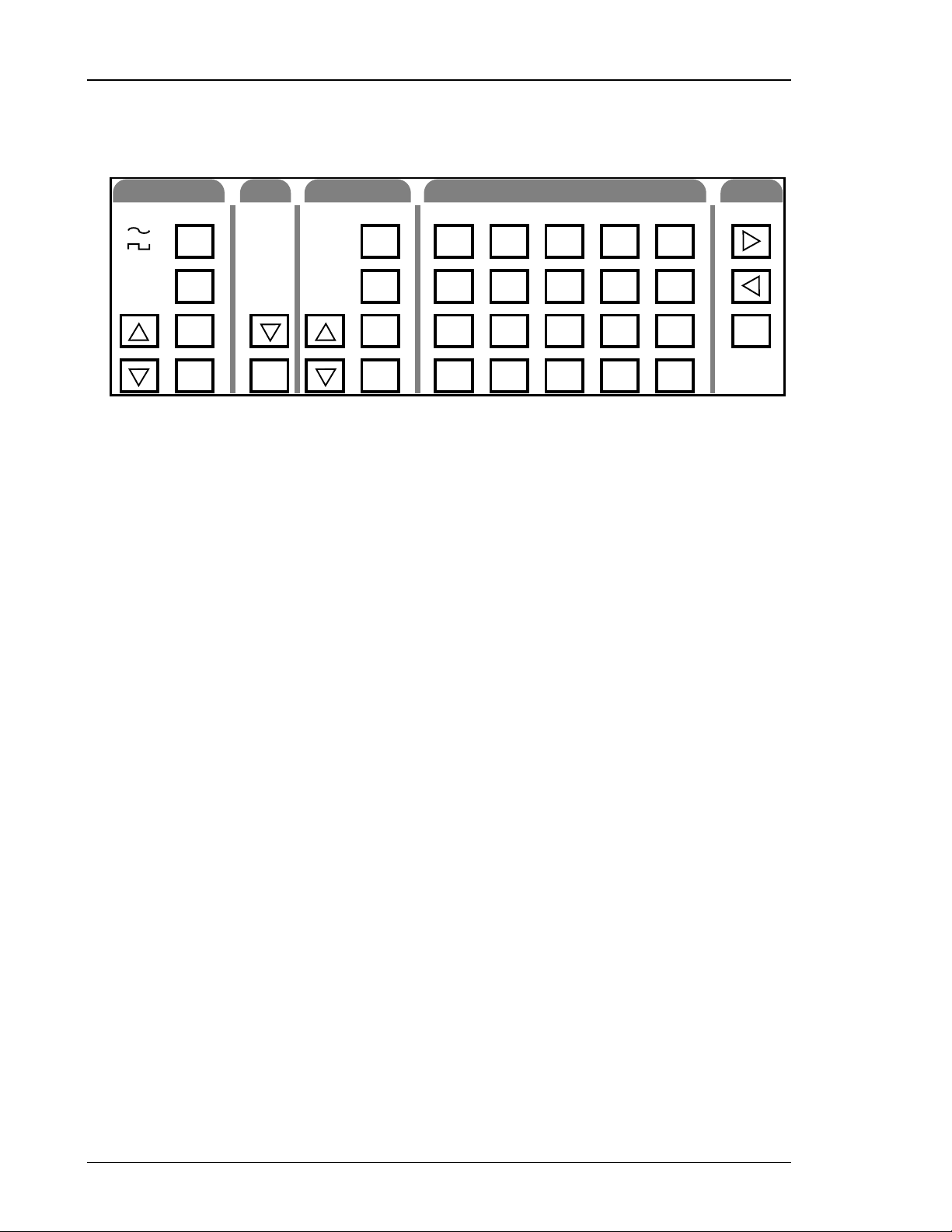
Keypad
FUNCTION
WHT NOISE
PINK NOISE
2-TONE
FREQ
AMPL
OFFST
ON/OFF
OUTPUT
UNBAL
BAL
DIGITAL
(SHIFT)
TRIGR
Function Keys
These keys control the main function output. The [∧] up and [∨] down function keys
select between the main output functions. [FREQ], [AMPL] and [OFFST] select the
output frequency, amplitude and DC offset voltage. [ON/OFF] turns the output on and
off.
Output Selection Key
SECONDARY MODIFYENTRY
LIN SWP
LOG SWP
BURST
BW NOISE
SWP/BURST
ON/OFF
TRIG SRC
START
CENTER
DEPTH
STOP
BW
BURST CNT
RATE
SHIFT
SHIFT STO RCL CLR
F STEP F STEP ENA DIG FREQ # BITS
+/-
GPIB RS232 CAL SRQ
.
T2 MODE
0
50 150 600
7
4
T1/T2
1
Figure 2-3 Keypad
HI Z
Vrms
%
DIG MODE
8
5
DIG 1 DIG 2 DIG 3
2
Vpp/DC
9
6
3
dB
DIG 0
dBm
kHz
dBV
Hz
LOCAL
DISP REL
REL
The [∨] key changes the output configuration from one of the three choices: unbalanced,
balanced and digital. Pressing the [∨] once moves one entry down the list; pressing the
[SHIFT](∧) moves one entry up the list.
Trigger Key
The [TRIGR] key begins singly triggered modified functions, like single sweeps or
bursts.
Modify Function Keys
These keys control the function output modification commands for sweeps, bursts or
bandwidth limited noise. The [∧] up arrow and [∨] down arrow keys select the
modification type. The [SWP/BURST] key turns the modification function on and off.
The other keys select different function modification parameters (start frequency, burst
depth).
Only modify functions that are allowable for the current function type (sine, square,
noise...) can be selected (i.e. sweep can be selected for sine or square, but not white
noise). Only modify parameters (START FREQ, STOP FREQ ...) that are valid for the
selected modify function can be changed. If a currently invalid modify parameter is
selected, the unit will beep and display “not APPL” (not applicable). If a function type
DS360 Ultra Low Distortion Function Generator
Page 29

Shift Key
Numeric Keys
Front Panel Features 2-7
change causes the currently displayed modify function to become invalid, the display
will revert to the frequency [FREQ] display.
The [SHIFT] key is used to select functions printed above the keys. Press the [SHIFT]
followed by the [function] key to select the desired function. When the shift key is
pressed, the shift LED will light. This indicates that the keypad is in “shifted” mode.
Pressing [SHIFT] a second time will deactivate shift mode. Note that in the manual,
whenever [SHIFT] is indicated, the desired function is printed above the key, not on
the key itself.
The numeric keypad allows for direct entry of the DS360’s parameters. To change a
parameter value, type the new value, followed by one of the [units] keys. A typing error
may be corrected by pressing the [CLR] key, which recalls the old value. The [+/-] key
may be selected at any time during numeric entry.
Units Keys
Cursor Keys
Rel Key
The units are used to terminate numeric entries. Press the key with the desired units to
enter the typed value. Some parameters have no particular units and any of the units keys
may be used. When the amplitude is displayed, pressing one of the units keys will cause
the display to change the units to the type pressed. This means that the amplitude display
can changed from Vpp, Vrms, dBm and dBV without entering a new value.
The [>] cursor right and [<] cursor left keys move the flashing digit to the right and left
of the display. They also switch between parameters which have a list of choices.
The [REL] key changes the amplitude display to the relative display mode. The
amplitude is displayed in dB relative to the value when [REL] was pressed. Pressing
[REL] a second time changes the amplitude display back to normal. Pressing
[SHIFT][REL] shows the Vpp amplitude that the display is rel’d to.
DS360 Ultra Low Distortion Function Generator
Page 30

2-8 Front Panel Features
Outputs
BNC OUTPUT
XLR OUTPUT
JACK OUTPUT
+
+
–
40V max.
Function Output
The three output types are connected in parallel. There are three separate sets of output
connectors: BNC, XLR and banana plugs. The different output signals are the positive
output, negative output, common and chassis ground. The connectors are configured as
listed below.
Function Output Connections
Output Signal BNC Connection XLR Connection Banana Plug
Positive Output
Negative Output
Common Both BNC Shields Pin 1 Common (black) jack
Ground Pin 4 Ground (green) jack
+ BNC Center contact
- BNC Center contact
–
Figure 2-4 Outputs
Pin 2 + (red) jack
Pin 3 - (white) jack
COMMON
40 VDC MAX.
GROUND
TRIGGER/GATE IN
SYNC OUT
TTL
TTL
The positive and negative outputs are both referenced to the common, which may be
floated +/-40 V
selectable. If the output is terminated into an incorrect impedance the output amplitude
will be incorrect and may exhibit increased distortion.
from the chassis ground. The output impedance of the outputs is
DC
Sync Output BNC
This output is a squarewave synchronized to the main function output. Its shield is
connected to chassis ground and cannot be floated.
Trigger / Gate In BNC
A low to high TTL signal on this input begins externally triggered bursts and sweeps.
For gated output, a TTL high gates the output on and a TTL low gates the output off. The
BNC shield is connected to chassis ground and cannot be floated.
DS360 Ultra Low Distortion Function Generator
Page 31

Indicators
Front Panel Features 2-9
STATUS
REM SRQ
ACT ERR
OUTPUT
ON
OFF
TRIG'D
IMPEDANCE
50
150
600
HI Z
Figure 2-5 Indicator LED’s
Status LEDs
These 4 LEDs indicate the DS360’s status.
Status LEDs
Name Function
REM
The DS360 is in GPIB remote status. The [>] cursor right key returns local control.
SRQ The DS360 has requested service on the GPIB.
ACT Flashes for RS232 or GPIB activity.
ERR Flashes on error in a command.
Configuration LEDs
These LEDs indicate the output configuration, source impedance and triggering mode of
the DS360.
TRIGGER
INT
EXT
SINGLE
GATE
FREQ
AMPL
STP/BWSTR/C
TONE 2TONE1
TRIGRCOUNT
OFFSET
REL
DEPTH
RATE
Configuration LEDs
Heading Display LED Parameter
OUTPUT ON
OFF
TRIG’D
IMPEDANCE 50
150
600
Hi-Z
TRIGGER INT
EXT
SINGLE
GATE
Output On
Output Off
Sweep or Burst Triggered
50 Ω Output Impedance
150 Ω Output Impedance
600 Ω Output Impedance
Hi-Z Output Impedance
Internal Trigger for Sweeps or bursts
External Trigger for Sweeps or Bursts
Single Trigger for Sweeps or Bursts
External Gate for Bursts only
DS360 Ultra Low Distortion Function Generator
Page 32

2-10 Front Panel Features
Parameter LEDs
These LEDs indicate which parameter is currently displayed in the parameter display.
Parameter LEDs
Display LED Parameter
FREQ Output Frequency
AMPL Output Amplitude
OFFSET Output Offset
STARTF Start Frequency for Sweeps
Center Frequency for Bandwidth Limited Noise
STOPF Stop Frequency for Sweeps
Cutoff Frequency for Bandwidth Limited Noise
REL Indicates that the amplitude display is in REL mode. Does not indicate a specific
display.
TONE1 Indicates that Amplitude and Frequency Displays refer to TONE 1. Does not
indicate a specific display.
TONE2 Indicates that Amplitude and Frequency Displays refer to TONE 2. Does not
indicate a specific display.
DEPTH Off Level Depth for Bursts
COUNT Burst Count for Bursts
TRIGR Trigger Source for Sweeps and Bursts
RATE Burst Rate for Bursts
DS360 Ultra Low Distortion Function Generator
Page 33

Display
Front Panel Features 2-11
Parameter Display
This 8 digit display shows the value of the currently displayed parameter. Error, status
messages and configuration information may also appear on the display.
Units LEDs
These LEDs indicate the units of the displayed value. If no LED is lit the number
displayed has no units or is seconds (for noise bursts).
Display LED Meaning
Vrms V
Figure 2-6 Display
Units LEDs
Hz Hertz
dB dB relative to preset value
V
P-P
kHz Kilohertz
dBV dB relative to 1 V
V
DC
% % (used with BURST DEPTH)
dBm dB relative to 1mW into selected source impedance
Volts Peak-to-Peak
Volts DC
RMS
into selected source impedance
RMS
Hz dB
kHz dBV
%dBm
Vp-p
VDC
Vrms
DS360 Ultra Low Distortion Function Generator
Page 34

2-12
Rear Panel Features
Power Entry Module
The power entry module is used to fuse the AC line, select the line voltage and block
high frequency noise from entering or exiting the instrument. The DS360 uses a
detachable three wire power cord for connection to the power source and the protective
ground. All exposed metal parts of the unit are tied to the outlet ground to protect against
electrical shock. Always use an outlet which has a properly connected protective ground.
Caution
CHASSIS
GROUND
AES/EBU
COAX OPTICAL
SPDIF
DIGITAL OUTPUT
FUSE
PULL
LINE : 48-66 Hz
FUSE :
1/2 A @ 100/120V
1/4 A @ 220/240V
STANFORD RESEARCH SYSTEMS
MODEL DS360 ULTRA LOW DISTORTION
SRS
FUNCTION GENERATOR. MADE IN U.S.A.
Verify that the LINE VOLTAGE SELECTOR card is set so the correct AC
input voltage value is visible. For continued protection against fire hazard
SWEEP OUT BURST TRIG OUT
WARNING
!
USE CORRECT FUSE.
WARNING
!
No user serviceable parts inside. Refer to user
manual for safety notice. Service by qualified
personnel only.
IEEE-488 STD PORT
RS232 (DCE)
Figure 2-7 Rear Panel
This instrument may be damaged if operated with the LINE VOLTAGE SELECTOR set
to the wrong AC line voltage, or if the wrong fuse is installed.
Do not attempt to service or adjust this instrument while it is plugged into a live outlet.
Line Voltage Selection
The DS360 operates from a 100, 120, 220 or 240 V
having a line frequency of 50 or 60 Hz. Before connecting the power cord to a power
source, verify that the LINE VOLTAGE SELECTOR card, located in the rear panel fuse
holder, is set so the correct AC input voltage is visible.
Conversion to other AC sources requires a change in the fuseholder voltage card position
and fuse value. Disconnect the power cord, open the fuse holder and rotate the fuse lever
to remove the fuse. Remove the small printed circuit board and select the operating
voltage by orienting it so the correct voltage is visible when pushed back into its slot.
Rotate the fuse-pull lever back to its normal position and insert the correct fuse into the
holder.
nominal AC power source
RMS
Line Fuse
Verify that the correct fuse is installed before connecting the line cord. For 100/120
V
use a 1 amp fuse. For 220/240 V
RMS
use a 1/2 amp fuse.
RMS
DS360 Ultra Low Distortion Function Generator
Page 35

Outputs and Computer Interface
WARNING
!
Verify that the LINE VOLTAGE SELECTOR card is set so the correct AC
input voltage value is visible. For continued protection against fire hazard
USE CORRECT FUSE.
Rear Panel Features 2-13
AES/EBU
COAX OPTICAL
DIGITAL OUTPUT
AES-EBU
The AES-EBU (XLR) interface supports the professional digital audio interface format
(IEC-958) and can transmit 16-20 bit wide data at data rates of 32, 44.1 and 48 kHz.
S/PDIF
The SPDIF/EIAJ coax and fiber optic outputs support the Sony-Philips Digital Interface
and EIAJ digital audio data formats. The transmitter sends 16 bit wide data at 32, 44.1
and 48 kHz.
IEEE-488 Connector
SWEEP OUT BURST TRIG OUT
SPDIF
Figure 2-8 Digital Outputs & Computer Interfaces
The 24 pin IEEE-488 connector allows a host computer to control the DS360 via the
IEEE-488 (GPIB) instrument bus. The GPIB address of the unit is accessed by pressing
[SHIFT][GPIB]. The [>] cursor right key is the instrument “local” key.
Serial RS232 Connector
The RS232 interface connector is configured as a DCE (transmit on pin 3, receive on pin
2). The Baud Rate is accessed by pressing [SHIFT][RS232]. The interface parameters
are: word length 8 bits, no parity and 2 stop bits.
Sweep Out
This output generates a short TTL pulse at the beginning of each sweep. It can be used to
synchronize an external device to a sweep. Its shield is connected to chassis ground and
cannot be floated.
DS360 Ultra Low Distortion Function Generator
Page 36

2-14 Rear Panel Features
Burst Out
This TTL output goes high for the “ON” portion of a burst and low for the “OFF”
portion. It can be used to synchronize an external device to a burst. Its shield is
connected to chassis ground and cannot be floated.
DS360 Ultra Low Distortion Function Generator
Page 37

3-1
Chapter 3
Operation
The following sections describe the operation of the DS360. The first section describes the basics of
setting a function, including setting the function type, amplitude, frequency and offset. The second
section explains setting the output configuration, including the output type and source impedance. The
third section explains sweeps, bursts and bandwidth limited noise. The final section explains storing and
recalling setups, running self tests and setting up the computer interfaces.
In this Chapter
Power On 3-3
Caution 1-3
Reset 1-3
Setting Functions 3-4
Function Type 3-4
Frequency 3-4
Amplitude 3-5
Unbalanced Amplitude Ranges 3-6
Balanced Amplitude Ranges 3-7
Offset 3-8
Function On/Off 3-8
Output Configuration
3-9
Output Type 3-9
Source Impedance 3-10
Modify Function 3-11
Modify Function Type 3-11
Modify Function On/Off 3-11
Modify Function Parameters 3-11
Sweeps 3-11
Bursts 3-13
Bandwidth Limited Noise 3-16
Instrument Setup 3-19
Default Settings 3-19
Storing and Recalling Settings 3-19
GPIB Setup 3-20
SRQ 3-20
RS-232 Setup 3-20
Self Tests 3-21
DS360 Ultra Low Distortion Function Generator
Page 38

3-2 Operation
Troubleshooting 3-23
GPIB Problems 3-23
RS232 Problems 3-23
Error Messages 3-24
Operational Messages 3-25
.
DS360 Ultra Low Distortion Function Generator
Page 39

Power On
Power On
When power is first applied to the DS360 the unit will display its serial number and
ROM version. Next the DS360 will initiate a series of self-tests of the internal circuitry
and stored data. The test should take about 3 seconds and end with the message “TEST
PASS”. If the self-test fails the DS360 will display an error message indicating the
nature of the fault (see the TROUBLESHOOTING section at the end of this chapter for
more details). The unit will attempt to operate normally after a self test failure; press any
key to clear the error message.
Caution
This instrument may be damaged if operated with the LINE VOLTAGE SELECTOR set
for the wrong AC line voltage or if the wrong fuse is installed.
Reset
3-3
Turn the power on while holding down the [CLR] key and continue to hold it down for at
least 1 second to reset the unit. The unit will perform its self-tests and assume its default
settings.
Attention
The DS360 has two distinct modes: analog and digital. These are selected as described in
the output configuration section. When the unit is in one mode (digital or analog),
parameters of the other mode cannot be selected or quarried from either the front panel
or the computer interface. This chapter describes the operation of the analog mode; for
information on the digital mode, see Chapter 5.
DS360 Ultra Low Distortion Function Generator
Page 40

3-4
Setting Functions
The following section describes how to set the parameters for the basic functions of the DS360, including
function type, frequency, amplitude, offset and function on/off.
Function Type
The DS360 output function type is selected using the [∧] up and [∨] down function
arrow keys. Press the appropriate key until the desired function LED is lit. The peak-topeak amplitude will remain the same between different functions. If the amplitude is
displayed in any other units, they will be adjusted to reflect a constant peak-to-peak
voltage. If the modify function is enabled and the type is incompatible with the new
function, the modify function will be changed to a legal value (the parameters will
remain unchanged).
The available functions are sinewaves, squarewaves, white noise, pink noise and twotones. Sinewaves and squarewaves are self explanatory. White Noise is a Gaussian
weighted distribution, filtered to 200 kHz and is flat in amplitude over that region. Pink
Noise extends from 10 Hz to 200 kHz with a -3 dB/octave amplitude response. There are
two types of 2-Tones; sine-sine 2-tones and sine-square 2-tones. To display the current
mode, press [SHIFT][T2 MODE]. To change modes, press the [>] right or [<] cursor
key, or turn the spin knob. When in 2-Tone, only one set of parameters (amplitude,
frequency) are available at a time. To toggle between displaying Tone 1 and Tone 2
parameters, press [SHIFT][T1/T2].
Frequency
To display the current output frequency, press the [FREQ] key. The frequency is
displayed in Hz or kHz, depending on which unit LED is lit. The DS360 has 6 digits of
frequency resolution or 1 mHz, whichever is greater. Any non displayed digits are zeroed
to avoid having slightly different output frequencies for a given display value.
The frequency ranges and resolution are shown in the table below.
Frequency Range of Functions
Function Frequency Range Frequency Resolution
Sinewaves 0.001 Hz - 200.000 kHz 0.001 Hz or 6 digits
Squarewaves 0.001 Hz - 200.000 kHz 0.001 Hz or 6 digits
White Noise 200 kHz White Noise (fixed)
Pink Noise 200 kHz Pink Noise (fixed)
Sine-Sine Two-Tone
Tone1 & Tone2 0.001 Hz - 200.000 kHz 0.001 Hz or 6 digits
Sine-Square Two-Tone
Tone1 (Sine)
Tone2 (Square)
0.001 Hz - 200.000 kHz
0.1 Hz - 5.0 kHz
0.001 Hz or 6 digits
2 digits
DS360 Ultra Low Distortion Function Generator
Page 41

Setting Functions
If the function is set to White Noise or Pink Noise the character of the noise is fixed,
unless a modification function is active. The frequency is not adjustable and displays
“noise”.
The frequency of both Tone1 and Tone 2 may be set. For Sine-Sine 2-Tones, both
frequencies are set the same as for normal sines, as is Tone1 for Sine-Square 2-Tones.
The squarewave in sine-square two-tones has limited frequency range and resolution. It
can be set from 0.1 Hz to 5.0 kHz with 2 digits of resolution (i.e. 4.9 kHz or 110 Hz, not
104 Hz).
To set the frequency of a function, type the new value on the keypad and complete the
entry with the appropriate units (Hz, kHz). Or change the frequency by using the spin
knob. If too high a value is entered, the DS360 will beep and display “Range Err”. If a
value less than 0.001 Hz is entered, the frequency is set to 0.001 Hz.
For output frequency settings only, the spin knob increment can set to a value other than
the normal single digit increment (set by the [>] right and [<] left cursor keys). To
display the step size mode, press [SHIFT][FSTEP ENA]. To toggle between the normal
and the special step size mode, turn the spin knob or press either of the cursor keys. To
display the current special step size, press the [SHIFT] [F STEP] keys. To set the special
step size, type a new value and complete the entry with the appropriate units (Hz, kHz).
The spin knob cannot be used to enter the step size.
3-5
Amplitude
To display the current amplitude, press the [AMPL] key. The amplitude may be set and
displayed in Vpp, Vrms, dBm, dBV and dB from a relative value. The current units are
indicated by the LEDs at the right of the display. dBm is defined as dB relative to 1 mW
of power into the selected source impedance. dBV is defined as dB relative to 1 Vrms
into the selected source impedance. (See the section on setting impedance and output
configuration for more detail).The amplitude resolution is 4 digits or 1 µV, whichever is
greater for Vpp and Vrms. For dBm, dB and dBV it is 3 digits or 0.1 dB, whichever is
greater.
The units of the amplitude display may be changed between Vpp, Vrms, dBm and dBV
without changing the amplitude by pressing the corresponding units key. When the
DS360 is switched from one function to another, the peak-to-peak amplitude remains the
same, but the values for other units will change to reflect the new function. To change
the amplitude, type a new value on the keypad, followed by the appropriate units (Vrms,
Vpp, dBm, dBV) key. Or use the spin knob to modify the current value. If the DS360s
attenuator setting changes, the output will briefly go to zero as the amplitude is changed.
2-Tone Amplitude
The amplitudes of Tone1 and Tone2 are maintained separately from the other function
amplitudes (i.e. when changing from another function to 2-Tone, the amplitudes will be
the last 2-Tone amplitudes set, not the value of the previous function). In addition to the
amplitude limits shown below, the amplitudes of Tone1 and Tone2 cannot differ by more
than 1:1000 or:
DS360 Ultra Low Distortion Function Generator
Page 42

3-6
Setting Functions
If the amplitude of either Tone1 or Tone 2 is set outside of these limits, the unit will
beep, display the message “Adj 2tA” (adjusting 2Tone Amplitude) and modify the other
Tone amplitude so it is within the allowable range.
Relative Amplitude
Amplitude may be set in dB relative to a user defined value for all functions except 2Tone. To make the currently displayed value the relative value, press [REL]. To set the
value in dB (relative to the previously entered rel’d value), type the new value, followed
by the [dB] key. The “rel’d” value can be displayed in Vrms, dBm or dBV, without
changing the amplitude, by pressing the appropriate key. To display the “rel’d” value in
Vpp, press [SHIFT][REL] which will display the Vpp value briefly. Pressing the [REL]
key a second time takes the amplitude out of relative mode, as does entering a value in
Vrms, dBm or dBV.
Unbalanced Output Amplitude
The amplitude range is limited by the DC offset, since
(V
For a DC offset of zero, the amplitude range for each function is shown in the tables
below for different source impedance’s.
) + |VDC| ≤ 20 V |VDC| ≤ (200 * V
AC PEAK
$PS7RQH
$PS7RQH
≤≤
AC PEAK
)
Unbalanced Hi-Z Output Amplitude Ranges
Function Vpp Vrms dBm dBV
Sine
Square
White Noise # 10 µV - 40.00 V 1µV - 5.714 V
Pink Noise # 10 µV - 40.00 V 2µV - 5.000 V
2-Tone *
10 µV - 40.00 V 4 µV - 14.14 V
10 µV - 40.00 V 5 µV - 20.00 V
10 µV - 40.00 V 3 µV - 14.14 V
Unbalanced 50 ΩΩΩΩ Output Amplitude Ranges
Function Vpp Vrms dBm dBV
Sine
Square
White Noise # 5 µV - 14.40 V 1 µV - 2.057 V
Pink Noise # 5 µV - 14.40 V 1 µV - 1.800 V
2-Tone *
5 µV - 14.40 V 2 µV - 5.091 V
5 µV - 14.40 V 3 µV - 7.200 V
5 µV - 14.40 V 2 µV - 5.091 V
-102 - 27.1 -115 - 14.1
-102 - 27.1 -112 - 17.1
-102 - 27.1 -125 - 4.2
-102 - 27.1 -126 - 2.7
-102 - 27.1 -115 - 14.1
-108 - 23.0
-106 - 26.0
-119 - 13.1
-120 - 11.5
-108 - 23.0
DS360 Ultra Low Distortion Function Generator
Page 43

Unbalanced 600 ΩΩΩΩ Output Amplitude Ranges
Function Vpp Vrms dBm dBV
Sine
Square
White Noise # 5 µV - 20.00 V 1 µV - 2.857 V
Pink Noise # 5 µV - 20.00 V 1 µV - 2.500 V
2-Tone *
5 µV - 20.00 V 2 µV - 7.071 V
5 µV - 20.00 V 3 µV - 10.00 V
5 µV - 20.00 V 2 µV - 7.071 V
Balanced Output Amplitude
Since there is no offset allowed for balanced output, the amplitude is only limited:
Setting Functions
-112 - 19.2 -115 - 17.0
-112 - 19.2 -112 - 20.0
-112 - 19.2 -125 - 7.0
-112 - 19.2 -126 - 5.5
-112 -19.2 -115 - 17.0
3-7
V
AC PEAK
The amplitude range for each function is shown in the tables below for different source
impedance’s.
≤ 40 V
Balanced Hi-Z Output Amplitude Ranges
Function Vpp Vrms dBm dBV
Sine
Square
White Noise # 20 µV - 80.00 V 3 µV - 11.43 V
Pink Noise # 20 µV - 80.00 V 3 µV - 10.00 V
2-Tone *
20 µV - 80.00 V 8 µV - 28.28 V
20 µV - 80.00 V 10 µV - 40.00 V
20 µV - 80.00 V 8 µV - 28.28 V
Balanced 50 ΩΩΩΩ and 150 ΩΩΩΩ Output Amplitude Ranges
Function Vpp Vrms dBm dBV
Sine
Square
White Noise # 10 µV - 28.80 V 2 µV - 4.114 V
Pink Noise # 10 µV - 28.80 V 2 µV - 3.600 V
2-Tone *
10 µV - 28.80 V 4 µV - 10.18 V
10 µV - 28.80 V 6 µV - 14.40 V
10 µV - 28.80 V 4 µV - 10.18 V
-96 - 33.2 -109 - 20.2
-96 - 33.2 -106 - 23.2
-96 - 33.2 -119 - 10.2
-96 - 33.2 -120 - 8.70
-96 - 33.2 -109 - 20.2
-103 - 29.0
-100 - 32.0
-113 - 19.1
-114 - 17.6
-103 - 29.0
Balanced 600 ΩΩΩΩ Output Amplitude Ranges
Function Vpp Vrms dBm dBV
Sine
Square
White Noise # 10 µV - 40.00 V 2 µV - 5.714 V
Pink Noise # 10 µV - 40.00 V 2 µV - 5.000 V
2-Tone *
* The maximum amplitude for 2-Tones is based on the sum of the two signals. Additionally the
difference between the two signals is limited to 1000:1 (i.e. the smaller of the two can be no smaller
than 1000x less than the larger).
10 µV - 40.00 V 4 µV - 14.14 V
10 µV - 40.00 V 6 µV - 20.00 V
10 µV - 40.00 V 4 µV - 14.14 V
-106 - 25.2 -109 - 23.0
-106 - 25.2 -106 - 26.0
-106 - 25.2 -119 - 13.1
-106 - 25.2 -120 - 11.5
-106 - 25.2 -109 - 23.0
DS360 Ultra Low Distortion Function Generator
Page 44

3-8
Setting Functions
# The rms, dBm and dBV values for White & Pink Noise are based on the total power in the output
bandwidth (200 kHz) at a given peak-to-peak setting.
Offset
Press the [OFFST] key to display the DC offset. The DC offset range is limited by the
amplitude, since
|V
AC PEAK
| + |VDC| ≤ 20 V |V
| ≤ (200 * V
offset
AC PEAK
).
The offset has three digits of resolution, however the smallest increment is determined
by the sum of the peak AC amplitude and the DC offset. The tables below show the
offset range and resolution for given amplitude settings. Offset is not active for balanced
outputs and is the same polarity for both unbalanced outputs (a +2 V
offset sets both
DC
the positive and negative offsets to +2 V) for unbalanced outputs.
Unbalanced Hi-Z
|V
AC PEAK
0 to 12.59 mV
12.60 mV to 125.9 mV
126.0 mV to 1.259 V 1 mV
1.260 V to 20.00 V 10 mV
| + |VDC| Offset Resolution (VDC)
10 µV
100 µV
Unbalanced 50 ΩΩΩΩ
|V
AC PEAK
0 to 6.319 mV
6.320 mV to 63.19 mV
63.2 mV to 0.6319 V 1 mV
0.6320 V to 7.200 V 10 mV
| + |VDC| Offset Resolution (VDC)
10 µV
100 µV
Unbalanced 600 ΩΩΩΩ
|V
AC PEAK
6.320 mV to 63.19 mV
63.20 mV to 0.6319 V 1 mV
0.6320 V to 10.00 V 10 mV
To set a new offset, type the desired value on the keypad, followed by the [V
use the spin knob to modify the currently displayed offset value.
| + |VDC| Offset Resolution (VDC)
0 to 6.319 mV
Function On / Off
The output may be switched on or off by pressing the [ON/OFF] key. The output status
is indicated on the main display under the OUTPUT heading. When the output is off, the
output connectors are terminated into the select source impedance.
DS360 Ultra Low Distortion Function Generator
10 µV
100 µV
] key. Or
DC
Page 45

Output Configuration
This section describes how to configure the output type and source impedance of the DS360.
Output Type
The DS360 has two different output types: unbalanced and balanced. The currently
selected output type is indicated by the LED in the OUTPUT section. To change to the
other output selection, press [∨] output down key. The significance of the different
output types is listed below.
Unbalanced Output
An unbalanced output signal refers to a signal that is referenced to a common DC
potential. Peak-to-peak or RMS voltages are measured to that common level. Most
normal function generators use this configuration. Both the positive and negative outputs
of the DS360 have the selected source impedance and output voltage amplitude present.
The two signals are equivalent, the only difference being that the positive signal is 180°
out of phase with the negative signal.
3-9
Digital Output
When the unbalanced output is selected, the amplitude limits are set to the unbalanced
output values. The offset function is available. Offsets are the same polarity for both
outputs (a +2 V
offset will offset both the positive and negative outputs by 2 volts).
DC
Balanced Output
A balanced output signal refers to a signal that is measured to another signal, not a
common DC potential, although one may be present. Peak-to-Peak or RMS voltages are
measured from signal to signal instead of signal to common. This configuration is used
for many audio applications. Typically the measured voltage will be twice the voltage (or
+6 dB) from each signal to a common signal. The output voltage and source impedance
is measured between the positive and negative outputs on the DS360. The signals are the
same as for the unbalanced case (albeit a different amplitude), however their amplitude is
measured differently.
When the balanced output is selected, the amplitude limits are set to the balanced output
values. The offset function is not active, since offset has no meaning for a balanced
output.
Pressing [SHIFT]
the front panel analog output and enables the rear panel digital output, indicated by the
OUTPUT LED’s. Pressing [SHIFT
analog output mode. See Chapter 5 for information on configuring and operating the
digital output.
[∨] output down key selects the DS360’s digital output. This disables
]
[∨] output down key again returns the unit to the
DS360 Ultra Low Distortion Function Generator
Page 46

3-10
Output Configuration
Source Impedance
The source impedance of the DS360 can be set to different values. When the output of
the DS360 is terminated into the selected source impedance, the amplitude set on the
front panel will be the amplitude seen by the load. If the output is not terminated into the
selected load, the amplitude set on the front panel will be incorrect. If one of the source
impedance’s is selected (not Hi-Z), and the unit is terminated into a high impedance, the
amplitude will be double the set value. The Hi-Z should be used when the output is
terminated into a high impedance. The Hi-Z amplitude will be correct (<1% error) for all
load impedance’s larger than 5 kΩ.
The output impedance changes for unbalanced and balanced. Each output (positive and
negative) has the selected source impedance for unbalanced outputs. For balanced
outputs, each output has 1/2 the selected source impedance.
Source Impedance Unbalanced Balanced
Source Impedance for + or - Output
50Ω 50Ω 25Ω
150Ω 75Ω
600Ω 600Ω 300Ω
Hi-Z
25Ω 25Ω
The selected source impedance is displayed under the IMPEDANCE heading to the left
of the display. To change the impedance, press [SHIFT][impedance], where impedance
is either 50Ω, 150Ω, 600Ω or Hi-Z. It is not necessary to press an entry key to select
source impedance’s.
If changing the source impedance from Hi-Z or 600Ω to 50Ω or 150Ω would cause an
out of range amplitude or offset, the following will occur. The DS360 will beep, display
the message Adj volt and adjust the amplitude to 14.4V
and the offset to 0 VDC..
PP
DS360 Ultra Low Distortion Function Generator
Page 47

Modify Function
This section describes how to set the modify functions on the DS360, including sweeps, bursts and
bandwidth limited noise.
Modify Function Type
Modify functions are associated with the different output functions. Only the options
available for the currently selected function type are accessible in the MODIFY FUNC
list. Sweeps are available for sine and square waves; bursts are available for sines,
squares, white and pink noise; bandwidth limited noise is available for white noise only.
No modify functions are active for 2-Tones. Press the [∧] up or [∨] down keys in the
MODIFY FUNC area until the desired selection is lit. If you cannot select the desired
type of modify function, verify that the selected function type allows that modify
function type.
Modify Function On/Off
To activate or deactivate the currently selected modification, press the [ON/OFF] key in
the MODIFY FUNC area. The SWP/BURST LED is lit to indicate that the
modification function is active.
3-11
Modify Function Parameters
The parameters for modify functions can be entered whether the function is currently
active or not. Only modify parameters (START FREQ, STOP FREQ ...) that are valid for
the selected modify function can be changed. If a currently invalid modify parameter is
selected, the unit will beep and display “not APPL” (not applicable). If a function type
change causes the currently displayed modify function to become invalid, the display
will revert to the frequency display.
Sweeps
Frequency sweeps are active for sine and square waves. Sweeps are increasing in
frequency and can be linear or logarithmic in nature. Frequency changes during the
sweep are phase continuous, including the wrap around from stop to start frequency. The
rate can be set from 0.01 Hz to 3.1 kHz, with 2 digits of resolution. Sweeps can be
continuous, externally triggered or singly triggered. The DS360 has a Sweep output on
the rear panel that can be used to synchronize an oscilloscope or other external device to
the DS360 sweep output. Use the MODIFY FUNC [ON/OFF] key to begin or end
sweeping.
Note
Sweeps have an amplitude rise at the wrap around point (stop frequency to start
frequency transition) due to ringing in the reconstruction filter. The effect is minimal for
stop frequencies below about 130 kHz. If high stop frequencies and large output
amplitudes (>30 Vpp, unbalanced) are used, it is possible to cause the output to clip. To
DS360 Ultra Low Distortion Function Generator
Page 48

3-12
Modify Function
minimize this, keep stop frequencies below 130 kHz when sweeping at maximum
amplitude.
Sweep Type
Press the [∧] up or [∨] down key in the MODIFY FUNC area until the LIN SWP or
LOG SWP LED is lit. The output frequency of a linear sweep changes linearly during
the sweep time. The output frequency of a log sweep changes exponentially during the
sweep time, spending equal time in each decade of frequency (for example, in a log
sweep from 1 kHz to 100 kHz, the sweep will spend half of the time in the 1 kHz to 10
kHz range and the other half in the 10 kHz to 100 kHz range).
Sweep Trigger Source
Sweeps can be continuously triggered, externally triggered or singly triggered. Internally
triggered sweeps use an internal sweep rate generator (see the SWEEP RATE described
below) to set the sweep repetition rate. Externally triggered sweeps begin on the rising
edge of a TTL signal supplied by the user to the TRIGGER/GATE IN BNC on the front
panel. Singly triggered sweeps begin by pressing the front panel [TRIGR] key or from
one of the computer interfaces.
The current trigger source is indicated by an LED under the TRIGGER heading next to
the frequency display. To view the current trigger source for modification, press the
[SHIFT][TRIG SRC] keys. To change the trigger source, use the spin knob or [>] right
or [<] left cursor keys.
While the DS360 is sweeping, the TRIG’D (triggered) LED is lit. It should be lit
continuously for internally triggered sweeps. For external or single triggered sweeps, it
will be lit for the duration of the sweep only. If a new trigger is received during an
external or single triggered sweep including the specified dead time (see SWEEP RATE
for details on dead time), the ERR LED will flash and any triggers will be ignored.
Sweep Rate
The sweep rate can be set continuously from 0.01 Hz (100 s) to 3.1 kHz ( 0.32 ms) with
2 digits of resolution (for example, you can set 1.1 kHz, but not 101 Hz). The period of a
sweep is simply 1/Sweep Rate.
To display the current sweep rate, press the [RATE] key. To change the sweep rate, type
a new value on the numeric keypad, followed by the appropriate units (Hz or kHz). Or
use the spin knob to modify the current value. If a non-valid rate is entered, (1.001 kHz
for example) the DS360 will round the value down to the nearest legal value. If an out of
range value is entered, the DS360 will beep, display “Rate Err” and flash the ERR LED.
Internal Trigger
There are no additional restrictions on internal sweep rates.
External or Single Trigger
The DS360 synchronizes the external (or single) trigger signal to its internal clock.
Because of this, there is an uncertainty of between 0 and 0.317 ms from the start signal
DS360 Ultra Low Distortion Function Generator
Page 49

Modify Function
(from the TRIGGER IN, computer interface or front panel) and the actual beginning of
the sweep. The SWEEP OUT BNC signal, which goes high at the beginning of the
sweep, should be used if it is necessary to synchronize the DS360 with an external
device, instead of the triggering signal. In addition, there is a dead time of between 0 and
0.317 ms between successive sweeps. If a trigger comes during a sweep or during the
dead time following a sweep, it will be treated as an error and ignored. These factors
limit the maximum rate that a sweep can be triggered externally (or singly) to somewhat
less than for internally triggered sweeps. To never miss a trigger, the maximum external
(or single) trigger rate is given by: 1/(Ext Sweep Freq) = 1/(Sweep Rate) + 0.634 ms.
Sweeps can be triggered somewhat faster than this if it is permissible to skip triggers.
Trigger errors simply indicate that a trigger has been ignored, but do not effect the output
signal in any way.
3-13
Start and Stop Frequencies
The DS360 can sweep over any portion of its frequency range, from 0.001 Hz to 200.000
kHz. To display the current start or stop frequency, press the [START] or [STOP] key.
To change the start or stop frequency, type a new value using the numeric keypad,
followed by the appropriate units (Hz or kHz). If an out of range frequency is entered,
the DS360 will beep, display “FREQ Err” and flash the ERR LED.
Bursts
Bursts are active for sinewaves, squarewaves, white noise and pink noise. A burst of
sines or squares consists of a certain number of complete cycles at a particular level (the
“ON” level), followed by another number of cycles at a reduced level (the “OFF” level).
Time intervals (instead of number of cycles) are used for noise signals. This pattern can
be triggered, either internally, externally, or on a single-shot basis. Additionally the
output can be gated on and off by an external signal.
Bursts are programmed in # of counts for sine and square waves and in seconds for noise
signals. The “ON” time is entered as the Burst Count. The Burst Rate is the combination
of both the “ON” and “OFF” times as shown below.
BURST RATE = BURST COUNT + OFF CYCLES
The burst “OFF” level is set in percent or dB relative to the “ON” level and can range
from 0 to 100% in 0.1% increments or from 0dB to -60dB in 0.1dB increments. The
DS360 has a BURST output on the rear panel that can be used to synchronize an
oscilloscope or other external device to the DS360 burst output. This signal remains a
TTL high for the duration of the “ON” time and a TTL low for the “OFF” time. Use the
MODIFY FUNC [ON/OFF] key to begin or end bursting.
Burst Trigger Source
Bursts can be continuously triggered, externally triggered or singly triggered. Internally
triggered bursts use an internal burst rate generator (see the BURST RATE described
below) to set the repetition rate. Externally triggered bursts begin on the rising edge of a
TTL signal supplied by the user to the TRIGGER/GATE IN BNC on the front panel.
Singly triggered bursts begin by pressing the front panel [TRIGR] key or from one of the
DS360 Ultra Low Distortion Function Generator
Page 50

3-14
Modify Function
computer interfaces. In addition, the output can be gated on and off from the
TRIGGER/GATE IN BNC, with TTL high setting the “ON” level and TTL low setting
the “OFF” level.
The current trigger source is indicated by an LED under the TRIGGER heading next to
the display. To view the current trigger source for modification, press the [SHIFT][TRIG
SRC] keys. To change the trigger source, use the spin knob or [>] right or [<] left cursor
keys.
During the “ON” time for bursts the TRIG’D (triggered) LED is lit. If a new trigger is
received during an external or single triggered burst the ERR LED will flash. Any
triggers received during an external or single triggered burst will be ignored. Trigger
errors only indicate that a trigger occurred during a burst; there is no effect on the output
waveform.
Sine and Square Wave Bursts
Internal Burst Rate
The burst rate is the total number of cycles in a burst, both the “ON” and “OFF” cycles,
when generating internally triggered bursts. It is set in integer number of cycles and can
range from 2 to 65535 (1 for the 1/2 cycle output. See below). In addition, it must be at
least one count greater than the Burst Count. To display the current burst rate, press the
[RATE] key. To modify the rate, type the new value in number of counts and press any
of the entry keys. Or use the spin knob to modify the displayed value. If an illegal value
is entered, the unit will beep, display “Range Er” and flash the ERR LED. If a value
that is less than the current burst count is entered, the unit will beep, flash the ERR LED,
display “AdjBur” (adjust burst), and adjust the Burst Count to one less than the Burst
Rate.
External Burst Rate
External or single triggered sine or square bursts are synchronized to the output zero
crossings. Because of this, there is an uncertainty of 0 to one cycle from the start signal
(from the TRIGGER IN, computer interface or front panel) and the actual beginning of
the burst. The BURST OUT BNC signal, which goes high at the beginning of the burst
should be used if it is necessary to synchronize the DS360 with an external device,
instead of the triggering signal. This limits the maximum rate that a burst can be
triggered externally (or singly) to somewhat less than for internally triggered bursts. To
never miss a trigger, the maximum external (or single) trigger rate is given by:
2XWSXW)UHT
([W7ULJ)UHT
Bursts can be triggered somewhat faster than this if it is permissible to skip triggers.
Burst Count
The burst count is the number of “ON” cycles (or high level) in a burst. It is set in
integer number of cycles and can range from 1 to 65534. In addition it must be at least
one count less than the Count Rate. To display the current Burst Count, press the
[SHIFT][BURST CNT]. To modify the count, type the new value in number of counts
and press any of the entry keys. Or use the spin knob to modify the displayed value. If an
illegal value is entered, the unit will beep, display “Range Er” and flash the ERR LED.
<
%XUVW&RXQW
+
DS360 Ultra Low Distortion Function Generator
Page 51

Modify Function
If a value that is greater than or equal to the current burst rate is entered the unit will
beep, display “BurRatEr” ( burst rate error) and flash the ERR LED.
3-15
Noise Bursts
Internal Burst Rate
The burst rate for noise is set in seconds. Any entry key may be used and no units are
displayed. The rate can vary between 20 µs to 600.0 s, with 4 digits of resolution. In
addition, the rate must be greater than and within 4 digits of the Burst Count. To display
the current burst rate, press [RATE]. To modify the rate, type the new value (in seconds)
and press any entry key. Or use the spin knob to modify the displayed value. If an illegal
value is entered, the unit will beep, display “Range ER” and flash the ERR LED. If a
value less than the current burst count is entered, the unit will beep, flash the ERR LED,
display “AdjBur” and adjust the Burst Count to 1/10 of the current Burst Rate. If the
Burst Rate is adjusted to a value more than 4 digits above the current Burst Count, the
Burst Rate is adjusted to the lowest allowable value (i.e. if the initial Burst Count is
0.001s, setting the Burst Rate to 600s will adjust the Burst Count to 0.1s).
External Bursts Rate
External noise bursts are not synchronized to anything, so there isn’t the uncertainty
from the TRIGGER IN signal and the start of bursts that there is for sine or square
waves. To never miss a trigger, the maximum external (or single) trigger rate is given
by:
([W7ULJ)UHT
<
%XUVW&RXQW
when the burst count is expressed in seconds.
Burst Count
The burst count for noise is the “ON” time in a noise burst. Any entry key can be used
and no units are displayed. The burst count can vary between 10 µs to 599.9 s, with 4
digits of resolution. In addition, the burst count must be less than and within 4 orders of
magnitude of the Burst Rate. To display the current burst count, press [SHIFT][BURST
CNT]. To modify the count, type the new value (in seconds) and press any entry key. Or
use the spin knob to modify the displayed value. If an illegal value or a value greater than
or equal the current burst rate is entered, the unit will beep, display “Range Er” and
flash the ERR LED.
Burst Depth
The burst depth is the attenuation of the “OFF” level compared to the “ON” level. To
enter a specific “OFF” level it is necessary to enter an “ON” level and calculate the
required attenuation to generate the desired “OFF” level. The burst depth on the DS360
can vary from 0 to 100%, with a 0.1% resolution. It can also be displayed or entered in
dB, ranging from -60.0 dB to 0 dB with 0.1 dB resolution. 0% depth (no output) can only
be set in percent. If 0% is set and the units are changed to dB, the display will show
“-999” as an overflow value since it cannot be displayed in dB.
To view the current depth, press [SHIFT][DEPTH]. To change the depth, type the new
value followed by the appropriate units key (% or dB). Or use the spin knob to modify
DS360 Ultra Low Distortion Function Generator
Page 52

3-16
Modify Function
the current value. If an out of range value is entered, the unit will beep, display “Depth
Err” and flash the ERR LED.
Gated Output
When the DS360 is set to gated output mode (see Burst Trigger Source) the output is
gated on and off from the TRIGGER/GATE IN BNC. A TTL high level outputs the
“ON” level and TTL low the “OFF” level. For sine and square waves, level changing
occurs at zero crossings. Because of this there is an uncertainty of between 0 and one
cycle from the rising edge of the TRIGGER/GATE IN BNC and the actual level change
of the output. Similarly there is an uncertainty at the falling edge. The BURST OUT
BNC signal, which is high while the “ON” level is active should be used if it is necessary
to synchronize the DS360 with an external device instead of the external gating signal.
This is not a problem for gated noise signals, since it isn’t synchronized to anything.
1/2 Cycle Burst
The DS360 has a special mode where it can output a 1/2 cycle burst of a sine or square
waves. The polarity is fixed (positive for the positive output; negative for the negative
output). To use the 1/2 cycle burst count, type .5, followed by an entry key. The spin
knob cannot be used to enter this value. The burst rate can be set to any legal value and
all triggering modes are valid.
Bandwidth Limited Noise
Bandwidth limited noise is active for white noise only. The purpose of bandwidth limited
noise is to maximize the noise power in the frequency of interest. The bandwidth limited
white noise in the DS360 maintains a constant RMS voltage over nearly all bandwidths
and center frequencies (see information in the CENTER FREQUENCY section below
for more information). The bandwidth limiting is accomplished using a 3-Pole
Butterworth Filter, for both the high and low pass filters. Use the MODIFY FUNC
[ON/OFF] key to begin or end bandwidth limited noise.
Bandwidth
The Bandwidth of the bandwidth limited noise can be set to any of the following values:
100 Hz, 200 Hz, 400 Hz, 800 Hz, 1.60 kHz, 3.20 kHz, 6.40 kHz, 12.8 kHz, 25.6 kHz,
51.2 kHz or 102.4 kHz. These correspond to 1/2 bandwidth frequency spans, starting
from the full bandwidth of the white noise.
To display the current bandwidth, press the [BW] key. To enter a new value, type the
value followed by the appropriate units key (Hz or kHz). Or use spin knob to modify the
current value. If the bandwidth is not entered exactly, the DS360 will round down to the
next legal value for all values above 100 Hz; below 100 Hz will round to 100 Hz. If an
out of range value is entered, the DS360 will beep, display “Freq Err” and flash the ERR
LED.
DS360 Ultra Low Distortion Function Generator
Page 53

Modify Function
3-17
Center Frequency
The center frequency can vary from 0 Hz to 200.000 kHz in 200 Hz increments. To
display the current center frequency, press the [CENTER] key. To change the center
frequency, type a new value using the numeric keypad, followed by the appropriate units
(Hz or kHz). If an out of range frequency is entered, the DS360 will beep, display “Freq
Err” and flash the ERR LED.
For bandwidth limited noise with high center frequencies and/or wide bandwidths there
can potentially be a reduction in noise power. When
CENTER FREQUENCY + 1/2 BANDWIDTH > 200 kHz
the amplitude will be slightly reduced. This is due to the fact that the white noise
generator has a bandwidth of 200 kHz, so any part of the noise bandwidth above 200 kHz
will be filtered.
DS360 Ultra Low Distortion Function Generator
Page 54

3-18
Modify Function
DS360 Ultra Low Distortion Function Generator
Page 55

Instrument Setup
3-19
Instrument Setup
This section describes the DS360’s default settings, storing and recalling settings, setting the computer
interfaces and running the self-tests.
Default Settings
Press [RCL][0] to recall the DS360’s default settings. This is a good place to begin
whenever you wish to start the instrument from a known state. The default settings are
listed below. See Chapter 5 for information on the default settings for the digital output.
Default Settings
Setting Default Value
Function Sine
Frequency 1.00000 kHz
Amplitude 1.000 Vrms
Offset 0.00 V
Output On/Off On
Output Type Unbalanced
Output Mode Analog
Output Impedance Hi-Z
Modify Function Linear Sweep
Modify Function On/Off Off
Start Frequency 1.000 Hz
Stop Frequency 100.000 kHz
Sweep Rate 1.0 kHz
Trigger Source Internal
Burst Depth 50%
Burst Count 1
Burst Rate 10
2-Tone Tone 1 Frequency 1.00000 kHz
2-Tone Tone 2 Frequency 10.0000 kHz
2-Tone Tone 1 Amplitude 1 Vrms
2-Tone Tone2 Amplitude 1 Vrms
2-Tone Mode Sine-Sine
Bandwidth Limited Noise Center Frequency 0 Hz
Bandwidth Limited Noise Bandwidth 3.2 kHz
GPIB Address 8
RS-232 Baud Rate 9600
DC
Storing and Recalling Settings
Storing Settings
The DS360 can store up to 9 independent instrument setups in non-volatile RAM,
separate from the default settings ([RCL][0]). To store the current instrument setup, press
[STO] followed by a location number (1-9). After any of the units keys are pressed, the
message “Store Done” will be displayed to indicate that the settings have been stored.
DS360 Ultra Low Distortion Function Generator
Page 56

3-20 Instrument Setup
Memory location 0 is the location of the defaults and cannot be stored to. Storing to it
will generate a range error.
Recalling Settings
To recall a stored setting, press [RCL] followed by a location number (0-9). After
pressing any of the units keys to enter the location, the message “Rcl Done” will be
displayed to indicate that the settings have been recalled. If nothing had been stored in
the selected location or if the stored settings had been corrupted, the message “Rcl Err”
will be displayed. Note that [RCL][0] recalls the default settings.
GPIB Setup
Press [SHIFT][GPIB] to display the current GPIB address. Use the spin knob to modify
the address or enter the number directly from the keypad and one of the entry keys. The
GPIB address can be set from 0 to 30.
Pressing [SHIFT][GPIB] a second time will display the last 256 characters of data that
has been received by the DS360. This display is a scrollable 3 character window into the
DS360’s input data queue. The data is displayed in ASCII hex format, where each
character is represented by 2 hexadecimal digits. The most recently received character is
indicated by the decimal point to the right of the digit. Turning the spin knob to the left
moves the window earlier into the data queue; turning it to the right moves later into the
queue. The display window cannot be moved later than the last character received.
SRQ
RS-232 Setup
The user may issue an user SRQ (service request) over the GPIB. Only one SRQ (user or
otherwise) can be active at a time; the host computer must acknowledge any pending
SRQ’s before a new one is sent. Note that the user SRQ is in addition to the usual service
requests based on the unit’s status.
To issue an user SRQ, press [SHIFT][SRQ], followed by any of the entry keys. The
message “Send SRQ” will appear prior to pressing the entry key. After the entry key is
pressed (assuming that no other SRQ is pending), the message” “Sent SRQ” will appear,
and the SRQ LED will appear. The SRQ LED will go off after the host computer does a
serial poll of the DS360.
See Chapter 4 on programming for additional information on the GPIB.
Press [SHIFT][RS232] to display the RS-232 baud rate setting. Use the spin knob to
modify the baud rate. The baud rate cannot be entered directly from the keypad. Baud
rates supported are 300, 600, 1200, 2400, 4800, 9600 and 19.2 k.
Pressing [SHIFT][RS232] a second time will display the last 256 characters of data that
has been received by the DS360. This display is a scrollable 3 character window into the
DS360’s input data queue. The data is displayed in ASCII hex format, where each
DS360 Ultra Low Distortion Function Generator
Page 57

Self-Tests
Instrument Setup
character is represented by 2 hexadecimal digits. The most recently received character is
indicated by the decimal point to the right of the digit. Turning the spin knob to the left
moves the window earlier into the data queue; turning it to the right moves later into the
queue. The display window cannot be moved later than the last character received.
See Chapter 4 on programming for additional information on the RS-232.
The self tests check out much of the internal circuitry, including the CPU, data memory,
ROM program memory, calibration constants integrity, stored settings integrity, DSP and
DSP memory. The self tests are executed on power-up and take about 3 seconds to run. If
all the self tests pass, the unit will display “tESt PASS” and operate normally. If they
fail, the unit will stop and display an error message. Pressing any key will cause the unit
to attempt to operate normally. Typically the user should power cycle the instrument to
attempt to clear the error. Some errors are transient in nature and will disappear. If the
problems continue, contact Stanford Research Systems for service information.
See the TROUBLESHOOTING section later in this chapter for a list and explanation of
error messages.
3-21
DS360 Ultra Low Distortion Function Generator
Page 58

3-22 Instrument Setup
DS360 Ultra Low Distortion Function Generator
Page 59

Troubleshooting
Nothing Happens on Power On
Make sure that the power entry module on the rear panel is set for the correct line
voltage, that the correct fuse is installed and that the line cord is inserted all the way into
the power entry module. The selected line voltage should be visible through the clear
window in the power entry module, just below the fuse, when the power cord is
removed.
Reset
If the unit becomes “hung” or inoperative, or displays no sensible message, a full reset
may fix the problem. To perform a full reset, hold down the [CLR] key while turning the
power on. This procedure initializes the RAM and recalls all factory calibration values. It
also distroys any stored settings. If you only want to return the instrument to it’s default
state, press [RCL][0], which doesn’t clear all stored data.
3-23
Unable to Set Parameters
Be certain that the unit is set for the correct mode (analog or digital) for the parameters
being adjusted (i.e. number of bits cannot be set in analog mode). This is true for both
front panel and computer operation. The output mode is indicated by the LED’s in the
OUTPUT section.
GPIB Problems
Make certain that the GPIB address of the DS360 matches what the controller expects.
The address can set to any address from 0 to 30, however the default address is 8. If
possible it is a good idea to use this address, unless you are otherwise constrained. To
display the address, press [GPIB], and use the keypad or spin knob to modify it.
The DS360 will ignore its front panel keypad when Remote Enable (REN) is asserted by
the GPIB. This “REMOTE” state is indicated by the REM LED. To return to LOCAL
operation (ie to return control to the front panel) press the [LOCAL] key. Controlling
programs may inhibit the ability to return to LOCAL operation by asserting the LocalLockout state (LLO). The only way to return from this state is to release it over the GPIB
or by performing a total reset.
A linefeed character is sent with an End Or Identify (EOI), to terminate strings from the
DS360. Be certain that your controller has been configured to accept this sequence.
DS360 Ultra Low Distortion Function Generator
Page 60

3-24
Troubleshooting
RS-232 Problems
Make certain that the baud rate of the controller and the DS360 agree. The baud rate can
be set from 300 to 19.2 k; the default is 9600. If it is practical, it is a good idea to use this
value. To display the baud rate press [RS232], and use the keypad or knob to modify the
value.The DS360 is configured to send or receive: 2 stop bits, 8 data bits and no parity
bits.When data is being recieved by the DS360, the ACT LED will flash. If this LED is
not flashing there is no data being recieved by the DS360.
When connecting the DS360 to a PC use a standard PC serial cable, not a “null modem”
cable. The DS360 is a DCE (Data Communications Equipment) device, and should be
connected with a straight cable to a DTE device (Data Terminal Equipment). The
“minimum” cable needs pins 2, 3 and 7. For hardware handshaking, pins 5 and 20 (CTS
and DTR) should also be passed. Occasionally pins 6 and 8 (DSR and CD) will be
needed; these lines are always asserted by the DS360.
Error Messages
The DS360 has two types of error messages, operational error messages and self test
error messages. Operational errors include entering out of range values or incorrect units.
Self test error messages only occur when the unit is running its internal self tests.
Operational Errors
Message Meaning
AC-DC ER The Vac+|Vdc| value exceeded the limit for the current setting.
AC ERR The amplitude entered is out of the allowable range.
BUR.RAT.ER Burst Rate Error. Burst Count > Rate Count.
NO.Cal.JPR No Cal jumper. Calbyte cannot be written without setting the calibration jumper.
NOT APPL The parameter is not applicable to the current instrument setting.
OFF ERR The offset entered is out of the allowable range.
OUTQ ERR Output queue error. The output queue is full.
RANGE ER The value entered is out of the allowed range for the current parameter.
RCL ERR Memory error found on power up or when recalling a stored setting. (Also
occurs when recalling a setting that hasn’t been previously stored)
SYN ERR The command syntax is invalid.
TOUT ERR Time out error when writing DSP memory.
UNITS ER The units set with AMPL, T1AA, T2BA or DPTH commands are not allowable
or nonexistent.
DS360 Ultra Low Distortion Function Generator
Page 61

Troubleshooting
3-25
Self-Test Errors
Message Meaning
CPU ERR The DS360 detected a problem with the CPU.
CODE ERR XX The DS360 detected a ROM checksum error. XX is the expected checksum
value.
SYSD ERR The DS360 failed its RAM read / write test.
CALD ERR The calibration data in RAM is corrupted. The factory calibration data will be
reloaded from PROM.
DSP 0 DSP not responding. The instrument must be power cycled.
DSP 1
followed by: xxxxxx
DSP 2
followed by: xxxxxx
TST n This message displays an encoded version of the bits 0-3 of the test register (see
DSP data bus error. The message is followed by a six digit (hex) code,
corresonding to each data line (of 24) that is in error.
DSP address bus and memory cell error. The message is followed by a six digit
(hex) code, made up of three words.
Bits 0-15 are DSP address lines 0-15.
Bits 16-18 are set if there is an error on the X, Y or P memory spaces.
Bits 19-21 are set if there is an error in the low (D0-7), middle (D8-15) or high
(D16-23) bytes of the memory space.
the *TST command).
Other Messages
The DS360 displays a number of messages to inform the user of its operational status or
of actions the unit has taken. All possible messages are listed below.
Operational Messages
Message Meaning
ADDR xx GPIB address. The value xx is the current GPIB address.
ADJ BUR The Burst count has been adjusted to be lower then the current Rate count.
ADJ DFR The digital output frequency has been adjusted to an allowable range after
changing the sampling frequency.
ADJ VOLT The amplitude and offset has been adjusted to an allowable value after changing
the source impedance.
ADJ 2TA The non-selected 2Tone amplitude has been adjusted to within a 1:1000 range of
the currently selected tone.
ADJ 2TAll Tone 1 and Tone 2 amplitudes and offset have been adjusted to an allowable
value after changing the source impedance.
ADJ 2TFR Tone 2 Frequency has been adjusted after the Tone 2 mode was changed to
squarewave.
BAUD xxxx RS232 baud rate. The value xxxx is the current baud rate.
CLEAR Second selection of the CAL menu. If the calibration jumper is set correctly,
pressing any unit key will recall the default calbytes from PROM.
DS360 Ultra Low Distortion Function Generator
Page 62

3-26
LD DONE This message occurs after succesfully loading the DSP memory.
RECALL Recall menu. It should be followed by a number between 0-9.
RCL DONE This message will be displayed for about 1 second after a succesfull recall.
STORE Store menu. Should be followed by a number between 1-9. (Store 0 will generate
STO DONE This message will be displayed for about 1 second after a succesfull store.
SEND SRQ SRQ menu. Pressing any units key will generate a GPIB SRQ, assuming no other
SRQ SENT This message is displayed for about 1 second after a SRQ is successfully sent.
SRC.INT
SRC.ETN
SRC.SNGL
SRC.GATE
STEP OFF (/ON) Frequency Step Enable. (Valid for FREQ and 2Tone FREQ).
Troubleshooting
a Range Error).
SRQ is pending.
The Trigger Source for sweeps (int, ext, single) or bursts (int, ext, single, gate).
DS360 Ultra Low Distortion Function Generator
Page 63

Chapter 4
Remote Programming
In this Chapter
Index of Commands 4-2
Introduction 4-5
Communication with GPIB 4-5
Communication with RS-232 4-5
Status Indicators and Queues 4-5
Command Format 4-6
Interface Ready and Status 4-6
GET (Group Execute Trigger) 4-7
4-1
Command Syntax 4-8
Function Output Control Commands 4-9
Function 4-9
Frequency 4-9
Amplitude 4-9
Offset 4-9
Output Commands 4-9
Relative Mode 4-10
Frequency Step 4-10
2-Tone Commands 4-10
Digital Output Control Commands 4-12
Function 4-12
Frequency 4-12
Amplitude 4-12
Output Mode 4-12
Digital Output Configuration 4-12
Frequency Step 4-13
2-Tone Commands 4-13
Number of Bits 4-13
Modify Function Commands 4-14
Trigger 4-14
Modify Function 4-14
Trigger Source 4-14
Sweep Commands 4-14
Burst Commands 4-15
DS360 Ultra Low Distortion Function Generator
Page 64

4-2 Index of Commands
Bandwidth Limited Noise Commands 4-16
Setup Control Commands 4-17
System Commands 4-17
Front Panel Commands 4-17
Status Reporting Commands 4-18
Hardware Test & Calibration Commands 4-19
Status Byte Definition 4-21
Example Programs 4-23
GPIB Communications in C 4-24
RS-232 Communications in BASIC 4-25
DS360 Ultra Low Distortion Function Generator
Page 65

Index of Commands 4-3
Index of Commands
Variables
i, j, k, n integers
x real numbers
Function Output Control Commands
FUNC (?) i 4-9 0=sin, 1=sqr, 2=wht noise, 3=pink noise, 4=2Tone.
FREQ (?) x 4-9 Sets Output Freq to x.
AMPL (?) x 4-9 Sets Ampl to x; must include VP, VR, dB, dV or dm.
OFFS (?) x 4-9 Sets Output Offset to x.
OUTE (?) i 4-9 Output Enable (i=1), Disable (i=0).
OUTM (?) i 4-9 Output Mode 0=unbal, 1=bal.
TERM (?) i 4-10
RELA (?) i 4-10 Sets Relative Amplitude Mode ON (i=1) or OFF (i=0).
STPE (?) i 4-10 Freq Step Enable (i=1) Disable (i=0).
FSTP (?) x 4-10 Sets Freq Step to x.
TTAA (?) x 4-10 Sets Tone A amp to x; must include VP, VR, dB, dV or dm.
TTBA (?) x 4-11 Sets Tone B amp to x; must include VP, VR, dB, dV or dm.
TTAF (?) x 4-11 Sets Tone A frequency to x.
TTBF (?) x 4-11 Sets Tone B frequency to x.
TTMD (?) i 4-11 Sets 2-Tone Mode to sine (i=0) or square (i=1).
Source Impedance 0=50Ω, 1=150Ω, 2=600Ω, 3=HiZ.
Digital Output Control Commands
FUNC (?) i 4-12 0=sin, 4=2Tone (1, 2, 3 not allowed in digital mode).
DFRQ (?) x 4-12 Sets Digital Output Freq to x.
DAMP (?) x 4-12 Sets Digital Ampl to x (in %).
OUTD (?) i 4-12 Digital Output Enabled (i=1) or Disabled (i=0).
DIGM (?) i 4-12 Digital Output Mode 0=Professional, 1=Consumer.
DIGF (?) i 4-12 Digital Sampling Frequency 0=48 kHz, 1=44.1 kHz, 2=32 kHz.
STPE (?) i 4-13 Freq Step Enable (i=1) Disable (i=0).
FSTP (?) x 4-13 Sets Freq Step to x.
DTAA (?) x 4-13 Sets Digital Tone A amp to x (in %).
DTBA (?) x 4-13 Sets Digital Tone B amp to x (in %).
DTAF (?) x 4-13 Sets Digital Tone A frequency to x.
DTBF (?) x 4-13 Sets Digital Tone B frequency to x.
DIGB (?) i 4-13
Modify Function Commands
*TRG 4-14 Triggers a single sweep or burst.
MENA (?) i 4-14 Modify Function Enable (i=1) or Disable (i=0).
MTYP (?) i 4-14 Sets the modify function type to Lin Swp, Log Swp, Burst, BWNoise
TSRC (?) i 4-14 Sets the trigger source to Int, Ext, Single or Gate for i=0,1,2,3.
STFR (?) x 4-14 Sets Sweep Start Frequency to x.
SPFR (?) x 4-14 Sets Sweep Stop Frequency to x.
Sets Digital Number of Bits (16 ≤ i ≤ 20).
for i=0,1,2,3.
DS360 Ultra Low Distortion Function Generator
Page 66

4-4 Index of Commands
RATE (?) x 4-14 Sets Sweep Rate to x.
BCNT (?) x 4-15 Sets Burst Count to x (i=.5, 1-65534).
RCNT (?) i 4-15 Sets Burst Rate to x (i=1-65535).
DPTH (?) x 4-15 Sets Burst Depth to x; must include DB or PR (%).
NBCT (?) x 4-15 Sets Noise Burst Count to x.
NRCT (?) x 4-15 Sets Noise Rate Count to x.
BNDW (?) x 4-16 Sets Noise BW to 100, 200, 400, 1.6k, 3.2k, 6.4k, 12.8k, 25.6k, 51.2k,
102.4k.
CENF (?) i 4-16 Sets BW Noise Center Frequency to x.
Setup Control Commands
*IDN? 4-17 Returns the DS360 device identification string.
*RCL i 4-17 Recalls stored setting number i (0 to 9).
*SAV i 4-17 Saves the current instrument setting as setting number i (1 to 9).
KEYS (?) i 4-17 Simulates the pressing of a front pannel key.
Status Reporting Commands
*CLS 4-18 Clears all status registers.
*ESE (?) i 4-18 Sets/Reads the Standard Event Status Byte Enable register.
*ESR? {i} 4-18 Reads the value of the Standard Event Status register {or bit i only}.
*PSC (?) i 4-18 Sets the value of the power on status clear bit.
*SRE (?) i 4-18 Sets/Reads the Serial Poll Enable register.
*STB? {i} 4-18 Reads the value of the Serial Poll Byte {or bit i only}.
DENA (?) i 4-18 Sets/Reads the value of the DDS enable register.
STAT? {i} 4-18 Reads the value of the DDS register {or bit i only}.
Hardware Test and Calibration Commands
*TST? 4-19 Starts self test and returns status when done.
$FCL 4-19 Recalls the factory calibration bytes.
$FIL (?) n 4-19 Sets the State variable Filter to the n-th filter.
$NOF (?) n 4-19 Sets the filter mode to n (0,1 or 2).
$PRE (?) n 4-19 Sets the DS360 pre-amplifier attenuators to range n (0 to 31).
$PST (?) n 4-20 Sets the DS360 post-amplifier attenuators to range n (0 to3).
$WRD (?) j,k 4-20 Sets the value of calibration word j to k.
DS360 Ultra Low Distortion Function Generator
Page 67

Introduction
The DS360 Ultra Low Distortion Function Generator may be remotely programmed via
either the RS232 or GPIB (IEEE-488) interfaces. Any computer supporting these
interfaces may be used to program the DS360. Both interfaces are receiving at all times;
the DS360 will respond to the interface that sent the query.
Communicating with GPIB
The DS360 supports the IEEE-488.1 (1978) interface standard. It also supports the
required common commands of the IEEE-488.2 (1987) standard. Before attempting to
communicate with the DS360 over the GPIB interface, the DS360’s device address must
be set. To display the present address, press [SHIFT][GPIB]. The new address can be
modified by using the keypad, followed by an entry key, or by using the spin knob.
Communicating with RS232
Remote Programming 4-5
The DS360 is configured as a DCE (transmit on pin 3, receive on pin 2) device and
supports CTS/DTR hardware handshaking. The CTS signal (pin 5) is an output indicating
that the DS360 is ready, while the DTR signal (pin 20) is an input that is used to control
the DS360’s data transmission. If desired, the handshaking pins can be ignored and a
simple 3 wire interface (pins 2, 3 and 7) may be used. The RS232 baud rate is displayed
by pressing [SHIFT][RS232]. A new baud rate can be entered using the spin knob only;
the baud rate cannot be entered using the numeric keys. The word length, parity and
number of stop bits are fixed and cannot be modified. They are configured as follows: 2
stop bits, 8 data bits and no parity.
Status Indicators and Queues
To assist in programming, the DS360 has 4 interface status indicators which are located at
the left side of the display. The REM LED is on when the DS360 is in a remote state
(front panel locked out). The ACT LED is on whenever data is being received by the
DS360. The ERR LED flashes when an error, such as an illegal command or out of
range parameter, has been detected. The SRQ LED is on when the DS360 generates a
service request. SRQ remains on until a GPIB serial poll is completed.
To help find programming errors, the DS360 can display the interface buffers on the
display. The GPIB queue is accessed by pressing [SHIFT][GPIB] twice in succession.
The RS232 queue is accessed by pressing [SHIFT][RS232] twice in succession. The last
256 characters received by each interface can be displayed in a scrollable 3 character
window. The data is displayed in ASCII hex format, where each character is represented
by 2 hexadecimal digits. The most recently received character is indicated by a decimal
point to the right of the digit. Turning the knob counterclockwise moves the data window
earlier into the data queue; turning the knob clockwise moves the data window later into
the queue. The window cannot be moved later than the last character received.
DS360 Ultra Low Distortion Function Generator
Page 68

4-6 Remote Programming
Command Format
Communication with the DS360 uses ASCII characters. Commands may be in either
UPPER or lower case. A command to the DS360 consists of a four character command
mnemonic with an optional ?, arguments if necessary and a command terminator. The
terminator must be a linefeed <lf> or carriage return <cr> on RS232, or a linefeed <lf> or
EOI on GPIB. No command processing occurs until a terminator is received. Commands
function identically on RS232 and GPIB whenever possible. Command mnemonics
beginning with an asterisk (*) are IEEE-488.2 (1987) defined common commands. These
also function identically on RS232. Commands may require one or more parameters.
Multiple parameters are separated by a comma (,). Multiple commands may be sent on
the same line by separating them with semicolons (;).
There is no need to wait between commands. The DS360 has a 256 character buffer and
processes commands in the order received. If the buffer fills, the DS360 will hold off
handshaking on the GPIB and attempt to hold off handshaking on RS232. Similarly the
DS360 has a 256 character output buffer to store output until the host computer is ready
to receive it. If either buffer overflows, both buffers are cleared and an error is reported.
The present value of a particular parameter may be determined by querying the DS360
for its value. A query is formed by spending a question mark (?) with the command
mnemonic and omitting the desired parameter from the command. Values returned from
the DS360 are sent as a string of ASCII characters terminated with a carriage return
<cr> on RS232 and by a linefeed <lf> on GPIB. If multiple query commands are sent on
one command line (separated by semicolons), the answers will be sent individually, each
with a terminator.
Examples of Commands:
FREQ 1000 <lf > Set the Output Frequency to 1.0 kHz
*TRG <lf> Trigger a sweep or burst
FUNC? <lf> Query the output function.
Interface Ready and Status
The No Command bit in the Serial Poll Status Byte signals that the DS360 is ready to
receive and execute commands. When a command is received, this bit is cleared,
indicating that command execution is in process. No other commands will be processed
until this command is complete. Commands received during this time are stored in the
buffer to be processed later. Only GPIB serial polling will generate a response while a
command is in progress. When all pending commands have executed, the No Command
bit is set again. By checking the No Command bit, a host computer can ensure that all
previously sent commands have finished before sending a new command.
Since most commands execute very quickly, the host computer does not need to
continually check the No Command bit. Commands can be sent one after another and
they will processed immediately. However some commands, such as self tests, may
require a long time to execute. In addition, the host computer may need to check that
these commands executed without error. In these cases, the status should be queried.
DS360 Ultra Low Distortion Function Generator
Page 69

SRQ
Remote Programming 4-7
When using the GPIB interface, serial polling may be used to check the No Command bit
while operation is in progress. After the bit becomes set, the ERR bit may be checked to
verify successful completion of the command.
If the RS232 interface is used, or serial polling is not available, then the *STB ? and *ESR
? status query commands may be used to query the Status Bytes. Since the DS360
processes one command at a time, the status query will not be processed until the
previous command is complete. Thus a response to the status query itself signals that the
previous operation is finished. The query response may then be checked for various
errors.
The user may issue an user SRQ (service request) over the GPIB. Only one SRQ (user
or otherwise) can be active at a time; the host computer must acknowledge any pending
SRQ’s before a new one is sent. Note that the user SRQ is in addition to the usual service
requests based on the unit’s status. See the section on status bytes later in this chapter for
more information.
GET (Group Execute Trigger)
The GPIB command GET will have the same effect as a *TRG command. If the DS360
is configured for a single triggered sweep or burst, then the GET bus command will trigger
a sweep or burst. If the DS360 is not configured for one these, the command will be
ignored.
DS360 Ultra Low Distortion Function Generator
Page 70

4-8 Remote Programming
Command Syntax
The four letter mnemonic in each command sequence specifies the command. The rest of
the sequence consists of parameters. Parameters shown in { } are not always required.
Generally, parameters in { } are required to set a value in the DS360. Multiple parameters
are separated by commas. Multiple commands may be sent on one command line by
separating them with semicolons (;).
The present value of a parameter may be determined by sending a query command.
Commands that may be queried have a question mark in parentheses (?) after the
mnemonic. Commands that may ONLY be queried have a ? after the mnemonic.
Commands that MAY NOT be queried have no ?. A query is formed by including the
question mark ? after the command mnemonic and omitting the queried parameter from
the command. The query parameters shown in { } are NOT sent with a query. The query
returns the value of these parameters. Values are returned as a string of ASCII
characters.
NOTE: Do NOT send ( ) or { } as part of the command.
Variables are defined as follows:
i, j, k, n integers
x real numbers
All numeric variables may be expressed in integer, floating point or exponential formats
(i.e. the number five can be either 5, 5.0 or 05E1). Strings are sent as a sequence of
ASCII characters.
DS360 Ultra Low Distortion Function Generator
Page 71

Remote Programming 4-9
Function Output Control Commands
Note: The analog output control commands may be selected only when the analog output type is selected.
If these commands are sent when the unit is in digital mode a “Not Appl” (not applicable) message
will be displayed on the screen and syntax error will occur. The command OUTD0 (analog
output) should be sent at the beginning of any program that uses the analog output. Also be aware
that a couple of commands share common mnemonics and values with the digital output (FUNC,
STPE, FSTP).
FUNC (?) i
The FUNC command sets the output function type to i as shown below. The
FUNC? query returns the current function.
i Function
0 Sine
1 Square
2 White Noise
3 Pink Noise
4 2 Tone
FREQ (?) x
AMPL (?) x
The FREQ command sets the frequency to x Hertz. The FREQ? query returns
the current output frequency. The frequency is set and returned with 1mHz
resolution. If the current waveform is NOISE , an error will be generated and the
frequency will not be affected. This command doesn’t set the frequencies for 2Tones. See TTAF and TTBF commands for 2-Tone frequencies.
The AMPL command sets the output amplitude to x. The value x must consist of
the numerical value and a units indicator. The units may be VP (Vpp), VR
(V
), DB (dB in relative mode only, see RELA command below), DM (dBm)
RMS
or DV (dBV). For example, the command AMPL1.0DM will set the output to 1.0
dBm. Setting the amplitude to 0 Volts will produce DC only, (no AC component),
with the output controlled by the OFFS command. For amplitude- offset limits, see
chapter 3.
The AMPL? query will return the amplitude in the currently displayed units. For
example, if the display shows 10.0 V
, the AMPL? query will return 10VR. If
RMS
the units indicator is sent along with the command (such as AMPL?VP), the
returned units will match the units indicator and the amplitude will be returned in
those units.
This command doesn’t set the amplitude for 2-Tones. See TTAA and TTBA
commands for 2-Tone amplitudes.
DS360 Ultra Low Distortion Function Generator
Page 72

4-10 Remote Programming
OFFS (?) x
The OFFS command sets the output DC offset to x volts. The OFFS? query
returns the current value of the DC offset. For amplitude-offset limits see
chapter 3.
OUTE (?) i
The OUTE command disables the output for i=0 and enables the output for i=1.
The OUTE? query returns the current status of the output.
OUTM (?) i
The OUTM command selects the output mode of the instrument. For i=0 the
output is unbalanced and for i=1 it is balanced. The OUTM? query returns the
current output mode.
TERM (?) i
The TERM command sets the output source impedence as indicated in the table
below. The TERM? query returns the current source impedance setting. An error
will be generated if the output impedance selected is not valid for the current
output mode.
RELA (?) i
STPE (?) i
FSTP (?) x
i Source
Impedance
0
50 Ω
1
150 Ω
2
600 Ω
3 Hi-Z
The RELA command sets (queries) the relative mode for the output amplitude.
For i=1, the relative mode is active, with the current amplitude setting as the
relative amplitude. New values are set using dB relative to this value. For i=0 (or
when setting a value in units other than dB) the relative mode is inactive. This
command has no effect when 2Tone is selected.
The STPE command enables (i=1) or disables (i=0) the usage of the frequency
step, which is set by the FSTP command. The STPE? query returns the current
step enable mode.
The FSTP command sets the frequency step to x Hertz. The FSTP? query
returns the current step frequency. The step is active only for the main frequency
(FREQ) and STPE (step enable) = 1. The value x may range between 1mHz and
200kHz.
When the frequency step is enabled, it becomes the knob increment value.
DS360 Ultra Low Distortion Function Generator
Page 73

TTAA (?) x
TTBA (?) x
Remote Programming 4-11
The TTAA command sets the Tone 1 amplitude to x. The value x must consist of
the numerical value and a units indicator. The units may be VP (Vpp), VR (V
DM (dBm) or DV (dBV). For example, the command TTAA1.0VP will set the
Tone 1 to 1.0Vpp. The maximum value for the sum of Tone 1 and Tone 2
amplitude, as well as the ratio of the two, is limited as described in chapter 3. If
the DS360 must modify the amplitude of either Tone 1 or 2, due to under or over
ranging, a message is sent on the front panel and bit 3 in the DDS register is set.
The TTAA? query will return the amplitude in the currently displayed units. For
example, if the display shows 10.0 V
, the TTAA? query will return 10VR. If
RMS
the units indicator is sent along with the command (such as TTAA?VP), the
returned units will match the units indicator and the amplitude will be returned in
those units.
The TTBA command sets the Tone 2 amplitude to x. The value x must consist of
the numerical value and a units indicator. The units may be VP (Vpp), VR (V
DM (dBm) or DV (dBV). For example, the command TTBA1.0VP will set the
Tone 2 to 1.0Vpp. The maximum value for the sum of Tone 1 and Tone 2
amplitude, as well as the ratio of the two, is limited as described in chapter 3. If
the DS360 must modify the amplitude of either Tone 1 or 2, due to under or over
ranging, a message is sent on the front panel and bit 3 in the DDS register is set.
RMS
RMS
)
)
TTAF (?) x
TTBF(?) x
TTMD (?) i
The TTBA? query will return the amplitude in the currently displayed units. For
example, if the display shows 10.0 V
, the TTBA? query will return 10VR. If
RMS
the units indicator is sent along with the command (such as TTBA?VP), the
returned units will match the units indicator and the amplitude will be returned in
those units.
The TTAF command sets the Tone1 frequency to x Hertz. The TTAF? query
returns the current Tone1 frequency. The frequency is set and returned with
1mHz resolution.
The TTBF command sets the Tone 2 frequency to x Hertz. The TTBF? query
returns the current Tone 2 frequency. The Tone 2 frequency must be a legal
value for the 2-Tone type selected (see TTMD). If Tone 2 is a sinewave, the
frequency is set and returned with 1mHz resolution. If Tone 2 is a squarewave,
the frequency is set and returned with 2 digits of resolution (ie. 4.8kHz or 110Hz,
but not 101Hz).
The TTMD command sets the Tone 2 mode to either sine (i=0) or square
(i=1).The TTMD? query returns the current Tone 2 mode.
DS360 Ultra Low Distortion Function Generator
Page 74

4-12 Remote Programming
Digital Output Control Commands
Note: The digital output control commands may be selected only when the digital output type is selected. If
these commands are sent when the unit is in analog mode a “Not Appl” (not applicable) message
will be displayed on the screen and syntax error will occur. The command OUTD1 (digital output)
should be sent at the beginning of any program that uses the digital output. Also be aware that a
couple of commands share common mnemonics and values with the normal analog output (FUNC,
STPE, FSTP).
FUNC (?) i
The FUNC command sets the output function type to i as shown below. The
FUNC? query returns the current function. Note that square, white noise and pink
noise (i=1,2,3) are not valid when the instrument is in digital mode. If the
instrument mode is changed from analog to digital while the function is set to
square, white or pink noise, the function will revert to sine.
i Function
0 Sine
4 2 Tone
DFRQ (?) x
DAMP (?) x
OUTD (?) i
DIGM (?) i
The DFRQ command sets the digital frequency to x Hertz. The DFRQ? query
returns the current digital output frequency. The frequency is set and returned
with 1mHz resolution. This command doesn’t set the frequencies for 2-Tones.
See DTAF and DTBF commands for 2-Tone frequencies.
The DAMP command sets the digital output amplitude to x percent (%). The
DAMP? query will return the digital amplitude in percent. The amplitude is sent
and returned with 0.00001% resolution. This command doesn’t set the amplitude
for 2-Tones. See DTAA and DTBA commands for 2-Tone amplitudes.
The OUTD command selects the output mode of the instrument. For i=0 the
output is analog, for i=1 it is digital.The OUTD? query returns the current output
mode.
The DIGM command selects the digital output format of the instrument. For i=0
the format is professional and for i=1 it is consumer.The DIGM? query returns
the current digital output format.
DS360 Ultra Low Distortion Function Generator
Page 75

DIGF (?) i
STPE (?) i
FSTP (?) x
Remote Programming 4-13
The DIGF command sets (queries) the digital sampling frequency for the digital
output, based on the table below.
i Frequency
0 48.0 kHz
1 44.1 kHz
2 32.0 kHz
The STPE command enables (i=1) or disables (i=0) the usage of the frequency
step, which is set by the FSTP command. The STPE? query returns the current
step enable mode.
The FSTP command sets the frequency step to x Hertz. The FSTP? query
returns the current step frequency. The step is active only for the main frequency
(FREQ) and STPE (step enable) = 1. The value x may range between 1mHz and
200kHz.
DTAA (?) x
DTBA (?) x
DTAF (?) x
DTBF(?) x
When the frequency step is enabled, it becomes the knob increment value.
The DTAA command sets the Tone 1 digital amplitude to x percent (%). The
maximum value for the sum of Tone 1 and Tone 2 amplitude is limited as
described in chapter 5. The DTAA? query will return the amplitude in percent
(%).
The DTBA command sets the Tone 2 digital amplitude to x percent (%). The
maximum value for the sum of Tone 1 and Tone 2 amplitude is limited as
described in chapter 5. The DTBA? query will return the amplitude in percent
(%).
The DTAF command sets the Tone1 digital frequency to x Hertz. The DTAF?
query returns the current Tone1 frequency. The frequency is set and returned
with 1mHz resolution.
The DTBF command sets the Tone 2 digital frequency to x Hertz. The DTBF?
query returns the current Tone 2 frequency. The frequency is set and returned
with 1mHz resolution.
DS360 Ultra Low Distortion Function Generator
Page 76

4-14 Remote Programming
Modify Function Commands
Note: Most of the modify function parameters may be selected at any time that the unit is in analog mode.
To observe the changes effecting the output, be sure that the appropriate modifying type is selected and
the modify function is on. Some of the parameters cannot be modified for all settings. These are indicated
below. When this occurs, a “Not Appl” (not applicable) message will be displayed on the screen and
syntax error will occur.
If these commands are sent when the unit is in digital mode a “Not Appl” (not applicable) message will be
displayed on the screen and syntax error will occur. The command OUTD0 (analog output) should be sent
at the beginning of any program that uses the analog output.
*TRG
The *TRG command triggers a burst or a single sweep.The trigger source must
be set to SINGLE.
MENA (?) i
The MENA command enables the modify function for i=1 and disables it if i=0.
The MENA? query returns the current modify function status.
MTYP (?) i
TSRC (?) i
The MTYP command sets the modify function type to i as described in the table
below. The MTYP? query returns the current type.
i Modify Function
0 LIN SWEEP
1 LOG SWEEP
2 BURST
3 BW NOISE
If the modify function is changed to a type which is incompatable with the
currently selected output waveform, a range error will be sent and the command
will be ignored.
If the parameter currently being displayed is undefined for the new MTYP (for
example: start freq and burst), the “Not Appl” message will appear, a range error
will be returned and the display will be changed to FREQ, regardless of what was
displayed previously.
The TSRC command sets the trigger source for bursts and sweeps to i as
described in the table below. The TSRC? query returns the current trigger
source.
DS360 Ultra Low Distortion Function Generator
Page 77

STFR (?) x
SPFR (?) x
RATE (?) x
Remote Programming 4-15
i Source
0 INTERNAL
1 EXTERNAL
2 SINGLE
3 GATE (burst only)
If the trigger source is set to gate when the unit is in burst mode and the unit is
changed to sweep mode, the trigger source will change to internal.
The STFR (?) command sets (queries) the sweep start frequency to x Hertz. An
error will be generated if the start frequency is higher than the current stop
frequency.
The SPFR (?) command sets (queries) the sweep stop frequency to x Hertz. An
error will be generated if the stop frequency is lower than the current start
frequency.
The RATE command sets the sweep rate to x Hz. The value x is rounded to 2
significant digits and may range from 0.01 Hz to 3.1 kHz. The RATE? query
returns the sweep rate in Hertz.
BCNT (?) x
RCNT (?) i
DPTH (?) x
NBCT (?) x
The BCNT command sets the burst count to x (1 to 65534). The BCNT? query
returns the current burst count. The maximum value of x is limited to 1 less than
the value of RCNT (see below). If this is exceeded a range error will occur. The
burst count can also be set to .5, for a 1/2 cycle burst. The string “.5” must be
sent without a leading zero (do not send “0.5”!).
The RCNT command sets the burst rate count to i (1 to 65535). The RCNT?
query returns the current burst rate count. Setting RCNT less than or equal to the
current BCNT will adjust BCNT to RCNT-1 (to .5 if RCNT is 1). An “ADJ
BUR” message will be displayed and bit 3 (parameter adjust) will be set in the
DDS status byte.
The DPTH command sets the burst depth to x. The value x must consist of the
numerical value and a units indicator. The units must be DB (dB) or PR (%). If a
0% value is set, a query of DB will return -999 as an overflow value. The range
for x is 0% to 100% or 0dB to -60dB. A query must be followed by one of the
units indicators, for example DPTH?DB.
The NBCT command sets the Noise Burst Count to x. The NBCT? query the
Noise Burst Count. The minimum value of x must be within 4 digits of NRCT; the
DS360 Ultra Low Distortion Function Generator
Page 78

4-16 Remote Programming
maximum must be less than NRCT (i.e. for NRCT=3s, NBCT ranges from 1ms
to 2.999s).
NRCT (?) x
The NRCT command sets the Noise Rate Count to x. The NRCT? query returns
the current value of this parameter. x may range from 2 µs to 600 s.
If NRCT is set to a value lower than NBCT, NBCT is adjusted to NRCT/10; if
NRCT is set to a value more than 4 digits above NBCT, NBCT is adjusted to the
lowest allowable in that range (i.e. if NBCT=1ms, setting NRCT to 600s will
adjust NBCT to 100ms). An “ADJ BUR” message is displayed and bit 3 in the
DDS Status Byte is set in this case.
BNDW (?) i
The BNDW command sets the white noise bandwidth to one of the following
frequencies:100 Hz, 200 Hz, 400 Hz, 800 Hz, 1.6 kHz, 3.2 kHz, 6.4 kHz, 12.8
kHz, 25.6 kHz, 51.2 kHz, 102.4 kHz. The value i is always expressed in Hz.
Values lower then 100 Hz will set BNDW to 100 Hz; all other values will be
rounded down.
CENF (?) i
The CENF command sets the white noise center frequency to i , which ranges
from 0 to 200kHz. The resolution of i is 200 Hz; all settings will be adjusted to i
modulo 200. CENF? query returns the currently set value.
DS360 Ultra Low Distortion Function Generator
Page 79

Setup Control commands
Key Name
Key Code
Key Name
Key Code
FUNCTION UP
1021
FUNCTION DOWN
2122
OUTPUT UP
3223
TRIGGER
4324
MODIFY FUNC UP
5425
FREQ
6526
AMPL
7627
OFFS
8728
FUNCTION ON/OFF
9829
MODIFY FNC DOWN
10930
SWP BURST ON/OFF
11
Vrms / %
31
START/CENTER
12
Vpp / Vdc / dB
32
STOP/BW
13
kHz / dBm
33
RATE
14
Hz / dBV
34
SHIFT
15
not used
35
STO16right arrow
36
RCL17left arrow
37
CLR18REL38+/-19not used
39
(.)20not used
40
*IDN?
The *IDN? common query returns the DS360 device identification string. This
string is in the format: “StanfordResearchSystems,DS360,sn,vn” where sn is the
five digit serial number of the particular unit and vn is a 3 digit firmware version
number.
*RCL i
The *RCL command recalls stored setting number i, where i may range from 0 to
9. If the stored setting is corrupt or has never had anything stored in it, an
execution error will be generated. RCL0 recalls the default setting of the
instrument (see Chapter 3 for the default settings).
*RST
The *RST common command resets the DS360 to its default configuration,
initializes the unit and runs the self tests. It behaves the same as cycling the
power off and on. The communication setup is not changed. All other modes and
settings are set to the default conditions and values. This command takes some
time to complete.
Remote Programming 4-17
*SAV i
KEYS (?) i
The *SAV command saves the current instrument settings as setting number i,
where i ranges from 1 to 9 (setting number 0 is the default setting). An error will
be generated if data is saved to setting 0.
The KEYS command simulates the pressing of a front panel key. The KEYS?
query returns the keycode of the most recently pressed key. Keycodes are
assigned as follows:
DS360 Ultra Low Distortion Function Generator
Page 80

4-18 Remote Programming
Status Reporting Commands
Note: See tables at the end of the programming section for Status Byte definitions.
*CLS
The *CLS common command clears all status registers. This command does not
affect the status registers.
*ESE (?) i
The *ESE command sets the standard event status byte enable register to
decimal value i.
*ESR? {i}
The *ESR common command reads the value of the Standard Event Status
Register. If the parameter i is present, the value of bit i is returned (0 or 1).
Reading this register will clear it, while reading bit i will clear just bit i.
*PSC (?) i
The *PSC common command sets the value of the power-on status clear bit. If
i=1, the power-on status clear bit is set and all status registers and enabled
registers are cleared at power on. If i=0, the bit is cleared and the registers
maintain their values at power on.
*SRE (?) i
*STB? {i}
DENA (?) i
STAT? {i}
The *SRE common command sets the serial poll enable register to the decimal
value of parameter i.
The *STB common query reads the value of the serial poll byte. If i is present,
the value of bit i is returned (0 or 1). Reading this register has no effect on its
value as it is a summary of other status registers.
The DENA command sets the status enable register to the decimal value of
parameter i.
The STAT? query reads the value of the DDS status byte. If i is present, the
value of bit i is returned (0 or 1). Reading this register will clear it while reading
bit i will clear just bit i.
DS360 Ultra Low Distortion Function Generator
Page 81

Remote Programming 4-19
Hardware Test and Calibration Commands
*TST?
The *TST? common query runs the DS360 internal self tests. After the tests are
complete, the test status is returned as a one byte decimal value. If the value is 0,
no errors have been detected, otherwise the returned value is the encoded value
of the status of the test register described below.
bit Meaning
0 CPU error detected
1 ROM checksum error
2 RAM error detected
3 CALD calibration data chksum err
4 DSP error detected
5 unused
6 unused
7 reserved
Note: The following commands are primarily intended for factory calibration of the DS360 and
should never be needed during normal operation. Incorrect use of some of these commands can
alter the calibration of the DS360. If this happens, perform a full reset, as described in chapter
3.
$FCL
The $FCL command recalls the factory calibration bytes. This command will
generate an error if the calibration jumper is not in the correct position.
$FIL (?) i
The $FIL command sets the State Variable Filter to the i-th filter, when a
previous $NOF1 or $NOF2 command has been sent. In the $NOF0 mode this
command is disabled and the filter number is selected as a function of frequency.
The $FIL? query returns the currently selected filter number. The range for i is 0
to 36, where 0 means no filter is selected.
$NOF (?) i
The $NOF command sets the filter mode to 0, 1 or 2. Mode 0 is normal, the Z80
sets the appropriate filter function of frequency and tells the DSP which filter is
set. In mode 1, the Z80 sets the filter function of $FIL command and tells the
DSP that filter 0 is set. In mode 2, the Z80 sets the filter function of $FIL
command and tells the DSP which filter is set. The $NOF query returns the
current mode.
$PRE (?) i
The $PRE command sets the DS360 pre-amplifier attenuators to range i. The
integer i is the attenuation range which takes values from 0 to 31. Each range sets
the pre-attenuators to -1.25*i dB. Setting the amplitude will return the attenuators
to their normal position. The $PRE? query returns the current attenuator position.
DS360 Ultra Low Distortion Function Generator
Page 82

4-20 Remote Programming
$PST (?) i
The $PST command sets the DS360 post-amplifier attenuators to range i. The
integer i is the attenuation range, which takes values from 0 to 3. Each range sets
the post-attenuators to -20*i dB. Setting the amplitude will return the attenuators
to their normal position. The $PST? query returns the current attenuator position.
$WRD (?) j, {k}
The $WRDj,k command sets the value of calibration word j to k. Parameter j may
have a value from 0 to 950, while k may range from - 3270 to 65535 (see chapter
6 for calibration information). This command will generate an error if the
calibration jumper is not enabled. NOTE: This command will alter the calibration
of the DS360. To recall the factory calibration, use the $FCL command (Factory
Calibration Calbytes). Calibration bytes cannot be altered unless the warm-up bit
has been set.
DS360 Ultra Low Distortion Function Generator
Page 83

Status Byte Definitions
The DS360 reports on its status by means of three status bytes: the Serial Poll
Byte, the Standard Status Byte and the DDS Status Byte.
Upon power on, the DS360 may either clear all of its status enable registers or
maintain them in the state they were in on power down . The *PSC command
determines which action will be taken.
The status bits are set to 1 when the event or state described in the tables below
has occured or is present.
Serial Poll Status Byte
Bit Name Set When
0 Mod Done No modify function in progress
1 Mod Enable Modify function enabled
2 User SRQ User sends a front panel SRQ
3 DDS An unmasked bit in DDS is set
4 MAV The gpib output queue non-empty
5 ESB An unmasked bit in ESB is set
6 RQS/MSS SRQ (service request) has occured
7 No Command No unexecuted commands in the input queue
Remote Programming 4-21
The DDS and ESB bits are set whenever any unmasked bit (a bit with the
corresponding bit in the byte enable register set) in their respective status
registers are set. Use DENA and *ESE commands to set the enable register bits.
The DDS and ESB bits are not cleared until ALL enabled status bits in DDS and
ESB status bytes are cleared (by reading the status bytes or using *CLS).
Using *STB? to Read the Serial Poll Status Byte
A bit in the Serial Poll Status Byte is NOT cleared by using *STB?. The bit stays
set as long as the status condition exists. This is true even for RQS. RQS will be
set whenever the same bit in the Serial Poll Status Byte AND Serial Poll enable
registers are set. This is independent of whether a serial poll has occured to clear
the service request.
Using Serial Poll
Except for SRQ, a bit in the Serial Poll Status Byte is NOT cleared by polling the
status byte.When reading the status byte using a serial poll, the RQS bit signals
that the DS360 is requesting service.The RQS bit will be set to 1 the first time the
DS360 is polled following the service request. The serial poll automatically clears
the service request. Subsequent serial polls will return RQS cleared (0) until
another service request occurs. Polling the status byte and reading it with *STB?
can return different values for RQS. When serial polled, RQS indicates a service
request has occured. When read with *STB?, RQS indicates that an enabled
status bit is set.
DS360 Ultra Low Distortion Function Generator
Page 84

4-22 Remote Programming
Standard Event Status Byte
Bit Name Set When
0 Unused
1 Unused
2 Query Error Set on output queue overflow
3 Unused
4 Execution Error A command cannot be executed (Range Error)
5 Command Error Command Syntax Error or unrecognized
6 URQ Set by any keypress
7 PON Set by Power ON
This status byte is defined by IEEE-488.2 (1987) and is used primarily to report
errors in commands received over the communications interface. The bits in this
register stay set and are cleared by reading them using the *ESR command or by
the *CLS command.
(Parameter out of range, command not valid, etc.)
command
DDS Status Byte
Bit Name Set When
0 Trig’d A burst or sweep is triggered
1 Trig Err A trigger rate error occurs
2 unused
3 Adjust Msg A 2-Tone or Burst parameter is adjusted
4 Warmup Warm-up period expired
5 Test Error A self test error occurs
6 Cal Enabled 1 = calibration enabled
7 Mem Error The stored settings where corrupt
The Warm-up bit will be set and remain set after the warm up period has expired.
The rest of the bits in this register are set when the corresponding event occurs
and remain set until cleared by reading this status byte (*ESR) or by the *CLS
command.
DS360 Ultra Low Distortion Function Generator
Page 85

Example Programs
Using Microsoft C with the National Instruments GPIB card on a PC
To succesfully interface the DS360 to a PC via the GPIB interface, the
instrument, interface card and interface drivers must all be configured properly.
To configure the DS360, the GPIB address must be set in the [SHIFT][GPIB]
menu.The default address is 8; use this address unless a conflict occurs with
other instruments in your system. The DS360 will be set to GPIB address 8
whenever a reset is performed (power on with the CLR key pressed).
Make sure that you follow all of the instructions for installing the GPIB card. The
National Instruments card cannot be simply unpacked and put into your computer.
To configure the card , you may need to set jumpers and switches on the card to
set the I/O address and the interrupt levels. You must run the program
“IBCONF” to configure the resident GPIB driver for your GPIB card. Please
refer to the National Instruments manual for more information. In these examples,
the following options must be set with IBCONF:
4-23
Device Name: DS360
Device Address: 8
EOS Character: 0Ah (linefeed)
Terminate Read on EOS: Yes
Once all the hardware and GPIB drivers are configured, use “IBIC”. This
terminal emulation program allows you to send commands to the DS360 directly
from the computer keyboard. If you cannot talk to the DS360 via “IBIC”, then
your programs will not run.
Use the simple commands provided by National Instruments. Use “IBWRT” and
“IBRD” to send and receive from the DS360. After you are familiar with these
simple commands, you can explore more complex programming commands.
DS360 Ultra Low Distortion Function Generator
Page 86

4-24 Programming Examples
Example1: GPIB Communication in C language
/*
C program to demonstrate communication with the DS360 via GPIB.
Written in Microsoft C and uses National Instruments GPIB card.
Assumes DS360 is installed as device name DS360.
Refer to National Instruments for Device Name setup.
*/
#include <stdio.h>
#include <string.h>
#include <stdlib.h>
#include <dos.h>
#include <decl.h> /* National Instruments header files */
void main(void);
int ds360;
void main()
{
char cmd[40];
char start[20];
char stop[20];
if ((ds360 = ibfind(“DS360”)) < 0) /* open National driver */
{
printf (“Cannot find DS360\n”);
exit(1);
}
/* Now that the driver is located, reset the DS360 */
sprintf (cmd,“*RST\n”);
ibwrt(ds360,cmd,strlen(cmd)); /* send command */
/* Setup the DS360 as follows:
50kHz,square wave,1.5Vpp, -1.0Volt offset,display offset */
sprintf (cmd, “FREQ50000”;FUNC1;AMPL1.5VP;OFFS-1.5;KEYS8\n”);
ibwrt(ds360,cmd,strlen(cmd)_; /* send command */
/* Now, query the DS360 for the sweep start and stop frequencies */
sprintf(cmd, “STFR?\n”); /* ask for start freq */
ibwrt(ds360,cmd,strlen(cm)); /* send query */
ibrd(ds360,start,20); /* read back start freq*/
sprintf(cmd, “SPFR?\n”); /* ask for stop freq */
ibwrt(ds360,cmd,strlen(cm)); /* send query */
ibrd(ds360,stop,20); /* read back start freq*/
printf(“\n\n\n\n **** DS360 Setup Demo ****”);
printf(“\n\nDS360 Sweep Start Frequency = %eHz\n\n”,atof(start));
printf(“\n\nDS360 Sweep Stop Frequency = %eHz\n\n”,atof(stop));
}
DS360 Ultra Low Distortion Function Generator
Page 87

Programming Examples 4-25
Example 2: RS232 communication in BASIC language
BASIC program to demonstrate communication with the DS360 via RS232.
Program assumes the DS360 BAUD rate is set to 9600.
10 OPEN “com2:9600,n,8,2,cs,ds,cd” FOR RANDOM AS #1 ‘ Setup com2’
20 PRINT #1, “ ”
30 PRINT #1, “*RST” ‘ Reset the DS360’
40 GOSUB 190 ‘ Query DS360 and display result’
50 PRINT #1, “FREQ123456” ‘ Set new frequency to 123.456kHz’
60 GOSUB 190 ‘ Query DS360 and display result’
70 PRINT #1, “*RST” ‘ Reset the DS360’
80 FOR I=0 TO 4 ‘ Step through all functions ‘
90 PRINT #1, “FUNC”,I
100 GOSUB 190 ‘ Query DS360 and display result’
110 NEXT I
120 PRINT #1, “*RST” ‘ Reset the DS360’
130 PRINT #1, “AMPL0VP” ‘ Set amplitude to 0 volts’
140 FOR I=-5 TO 5 ‘ Set offset from -5V to 5v’
150 PRINT #1, “OFFS”,I ‘ and query each time’
160 GOSUB 190 ‘ Query DS360 and display result’
170 NEXT I
180 END
‘ Routine to query the DS360 frequency,’
190 PRINT #1, “FREQ?” ‘ amplitude and offset and display them’
200 INPUT #1, F
210 PRINT #1, “AMPL?VP”
220 INPUT #1, A
230 PRINT #1, “OFFS?”
240 INPUT #1, O
250 PRINT “Freq=“ ;F; “ Ampl=“; A; “ Offs=“; O
260 RETURN
DS360 Ultra Low Distortion Function Generator
Page 88

4-26 Programming Examples
DS360 Ultra Low Distortion Function Generator
Page 89

5-1
Chapter 5
Digital Output
The following sections describe the operation of the digital output of the DS360. The first section describes
the general specifics of the two common digital audio formats, the professional mode (AES-EBU) and the
consumer mode (S/PDIF). This is a very basic description of the standards; for further detail the user
should obtain the revelant standards. The second section how to set the various parameters for the digital
output.
In this Chapter
Overview 5-3
Digital Audio Encoding 5-3
Channel Status Bytes 5-3
AES-EBU 5-3
S/PDIF 5-3
DS360 Functions 5-4
Setting the Digital Output 5-7
Output Type 5-7
Function Type 5-7
Frequency 5-7
Amplitude 5-8
Sampling Frequency 5-8
Number of Bits 5-9
Digital Mode 5-9
Inactive Functions and Parameters 5-9
Storing and Recalling Settings 5-9
Default Settings 5-10
DS360 Ultra Low Distortion Function Generator
Page 90

5-2
Digital Output
DS360 Ultra Low Distortion Function Generator
Page 91

Digital Output 5-3
Overview
The DS360 is capable of generating digital domain waveforms in two different digital audio formats. The
two formats are AES-EBU, the professional digital audio format and S/PDIF, the consumer digital audio
format.
The following description is provided to help user understand the operation of the DS360’s digital output. It
by no means completely describes any of the specifications. For complete information, the user should
obtain copies of the relevant standards (AES-EBU 1992, IEC 958, ANSI S4.40-1992 and EIAJ CP-340).
Digital Audio Data Encoding
The two formats of digital audio communication are very similar in terms of data format
and encoding. Both formats support data rate of 32 kHz, 44.1 kHz and 48 kHz. Each
audio sample is transmitted in a sub-frame. Each sub-frame consists of a preamble, 4 bits
of auxiliary data, 20 bits of audio data and one bit each of validity, user, channel and
parity. Two sub frames are combined to make a frame, 192 of which make up a block.
The channel bits of each sub-frame are combined to make up 24 eight bit bytes that
convey status information. The first four bytes contain most of the important status
information. The significance of the first four bytes of channel status bits of each
interface are indicated below.
Professional Mode Channel Status Bytes
byte bit 0 bit 1 bit 2 bit 3 bit 4 bit 5 bit 6 bit 7
0 Pro=1 Audio Emphasis Lock Sampling Frequency
1 Channel Mode User Management
2 AUX Use Word Length Reserved
3 Reserved
Consumer Mode Channel Status Bytes
byte bit 0 bit 1 bit 2 bit 3 bit 4 bit 5 bit 6 bit 7
0 Pro=0 Audio Copy Emphasis Mode
1 Category Code Gen Stat
2 Source Number Channel Number
3 Sampling Frequency Clock Accuracy Reserved
DS360 Ultra Low Distortion Function Generator
Page 92

5-4 Digital Output
AES-EBU
The AES-EBU digital audio interface format is described in AES3-1992 (also ANSI
S4.40-1992). It is a means of serially transmitting two channels of periodically sampled
audio signals on a single shielded twisted wire pair. The transmission rate is such that both
audio channels can be transmitted in one sample period. Error detection is provided and
there is a format for transmitting channel status (control) and user specific information.
The control and user specific data is transmitted at the rate of one bit per sample.
The electrical specifications of the AES-EBU interface require that the data is transmitted
as a differential signal over a shielded twisted pair of wire and are compatible with RS-
422. The signal level are specified for a 110Ω source impedance at 2-7 VPP into a load
impedance of 110Ω. The connector provided on the DS360 is an XLR connector (male
pins, female shell) with the signal on pins 2 and 3 and pin 1 grounded. Any high quality
XLR cable can connect the DS360 to the device under test.
The major difference between the professional format (AES-EBU) and the consumer
format (S/PDIF) is in the definition of the channel status bytes and the number of bits per
word of data. The professional format can support between 16 and 24 bits per word of
data (although the DS360 only supports 16-20 bits). The consumer format only supports
16 bits of data per word.
S/PDIF
The S/PDIF, or Sony-Phillips Digital Interface Format is described in IEC 958 (also EIAJ
CP-340). It is a means of serially transmitting two channels of periodically sampled audio
signals on a single shielded wire or over a fiber-optic link. The transmission rate is such
that both audio channels can be transmitted in one sample period. Error detection is limited
to parity checking and there is a format for transmitting channel status (control) and user
specific information. The control and user specific data is transmitted at the rate of one bit
per sample.
The electrical specifications of the S/PDIF require that the data is transmitted in an
unbalanced configuration with an output impedance of 75Ω and a voltage of 0.5 V
PP
±20% into a 75Ω load, with no cable. The connector provided on the DS360 is an RCA
phono socket. In addition there is an fiber optic connector (Sharp GP1F32T), compatible
with most consumer digital audio fiber optic cables (Sharp GP1C321 type or equivalent).
The major difference between the professional format (AES-EBU) and the consumer
format (S/PDIF) is in the definition of the channel status bytes and the number of bits per
word of data. The professional format can support between 16 and 24 bits per word of
data (the DS360 supports 16-20 bits). The consumer format only supports 16 bits of data
per word.
DS360 Ultra Low Distortion Function Generator
Page 93

DS360 Digital Functions
The DS360 is capable of generating sine waves and two sine 2 Tones at sampling rates of
32 kHz, 44.1 kHz and 48 kHz. The frequency, amplitude, number of bits and sampling rate
can be set. The following tables show the values that are set for the different status bits
in each format. These cannot be changed.
Bit Name Meaning Value
Validity Sample Valid (0) 0 (Sample always valid)
User User Data 0 (No user data)
Channel Byte 0, bit 0 Pro 1 (Professional mode)
Channel Byte 0, bit 1 Audio 0 (Audio)
Channel Byte 0, bit 2 - 4 Emphasis 000 (No emphasis)
Channel Byte 0, bit 5 Locked 0 (Locked)
Channel Byte 0, bit 6 - 7 Sample Frequency 01 = 44.1 kHz, 10 = 48 kHz,
Channel Bytes 1 thru 22 Other channel status Always 0
Channel Byte 23 CRCC Depends on data
Professional Format Status Bits
11 = 32 kHz (bit 7,6)
Digital Output
5-5
Consumer Format Status Bits
Bit Name Meaning Value
Validity Sample Valid (0) 0 (Sample always valid)
User User Data 0 (No user data)
Channel Byte 0, bit 0 Pro 0 (Consumer Mode)
Channel Byte 0, bit 1 Audio 0 (Audio)
Channel Byte 0, bit 2 Copy Protect 1 (Copy permitted)
Channel Byte 0, bit 3 - 5 Emphasis 000 (No emphasis)
Channel Byte 0, bit 6, 7 Mode 00 Always
Channel Byte 1 Category Code 0 Always
Channel Byte 2 Source Number 0 Always
Channel Byte 3, bits 0 - 3 Sample Frequency 0000 = 44.1 kHz,
0010 = 48 kHz,
0011 = 32 kHz (bits 3210)
Channel Byte 3, bits 4 - 7 Clock Accuracy 0000 Always
Channel Bytes 4 thru 23 Reserved 0 always
DS360 Ultra Low Distortion Function Generator
Page 94

5-6 Digital Output
DS360 Ultra Low Distortion Function Generator
Page 95

Digital Output 5-7
Setting the Digital Output
The following section describes how to set the parameters for the digital output functions of the DS360,
including function type, frequency, amplitude, mode, number of bits and digital sampling frequency. Please
note that in digital mode several analog mode functions are disabled and cannot be selected.
All parameters for the digital output are independent from their analog counterparts. When the digital
mode is entered, the last digital output frequency used will be recalled, not the one previously used for the
analog outputs. There are separate computer interface commands to set the various parameters as well.
Output Mode
The DS360 has two different output modes: analog and digital. The currently selected
output is indicated by the LED in the OUTPUT section (balanced / unbalanced or digital).
Pressing [SHIFT] [∨] output down key toggles between the two different modes.
The operation for the balanced and unbalanced outputs is described in Chapter 3.
When the digital mode is selected, the front panel analog output is disabled and the rear
panel digital output is enabled. Note that in digital mode several functions are disabled and
cannot be selected.
Function Type
The DS360 output function type is selected using the [∧] up and [∨] down function arrow
keys. Press the appropriate key until the desired function LED is lit. In digital mode only
sine waves and two sine 2 tone functions are available. Other functions cannot be
selected. When in 2-Tone, only one set of parameters (amplitude, frequency) are available
at a time. To toggle between displaying Tone 1 and Tone 2 parameters, press
[SHIFT][T1/T2].
Frequency
To display the current output frequency, press the [FREQ] key. The frequency is
displayed in Hz or kHz, depending on which unit LED is lit. The DS360 has 6 digits of
frequency resolution or 1 mHz, whichever is greater. Any non displayed digits are zeroed
to avoid having slightly different output frequencies for a given display value. The output
frequency for the digital output is maintained separately from that of the analog output
functions, so that when changing between digital and analog modes, the previous digital
frequency will be recalled.
The frequency ranges are shown in the table below. Frequency resolution is 6 digits or
0.001 Hz, whichever is larger.
DS360 Ultra Low Distortion Function Generator
Page 96

5-8 Digital Output
Frequency Range of Functions vs Sampling Frequency
Function 48 kHz 44.1 kHz 32 kHz
Sinewaves 0.001 Hz - 20.0 kHz 0.001 Hz - 20.0 kHz 0.001 Hz - 14.5 kHz
Two-Tones
(Tone1 & Tone2)
Amplitude
0.001 Hz - 20.0 kHz 0.001 Hz - 20.0 kHz 0.001 Hz - 14.5 kHz
The frequency of both Tone1 and Tone 2 may be set in the same manner as for normal
sines. To toggle between displaying Tone 1 and Tone 2 parameters, press
[SHIFT][T1/T2].
To set the frequency of a function, type the new value on the keypad and complete the
entry with the appropriate units (Hz, kHz). Or change the frequency by using the spin
knob. If too high a value is entered, the DS360 will beep and display “Range Err”. If a
value less than 0.001 Hz is entered, the frequency is set to 0.001 Hz.
For output frequency settings only, the spin knob increment can set to a value other than
the normal single digit increment (set by the [>] right and [<] left cursor keys). To display
the step size mode, press [SHIFT][FSTEP ENA]. To toggle between the normal and the
special step size mode, turn the spin knob or press either of the cursor keys. To display
the current special step size, press the [SHIFT] [F STEP] keys. To set the special step
size, type a new value and complete the entry with the appropriate units (Hz, kHz). The
spin knob cannot be used to enter the step size.
To display the current amplitude, press the [AMPL] key. The amplitude may be set and
displayed only in % (percent) of full scale, since volts or other units have no meaning in
the digital format. The current units (%) will be indicated by the LED at the right of the
display. The amplitude resolution is 0.00001%, with a range of 0 to 100.00000%. To
change the amplitude, type a new value on the keypad, followed by [%]. Or use the spin
knob to modify the current value. The amplitude for the digital output is maintained
separately from those of the analog output functions, so that when changing between
digital and analog modes, the previous digital amplitude values will be recalled.
2-Tone Amplitude
The amplitudes of Tone1 and Tone2 are maintained separately from the sine amplitude
(i.e. when changing from another function to 2-Tone, the amplitudes will be the last 2Tone amplitudes set, not the amplitude value of the sine). The amplitude limits for 2 tone
are a function of the sum of the two amplitudes. {i.e. 0 ≤ (Amp1 + Amp2) ≤ 100 %}
Digital Sampling Frequency
The digital sampling frequency can be set to three values: 48.0 kHz, 44.1 kHz and 32.0
kHz. These correspond to frequencies commonly used for digital audio tape, compact
disks and computer digital audio applications.
DS360 Ultra Low Distortion Function Generator
Page 97

To display the current sampling frequency, press [SHIFT] [DIG FREQ]. The message
“digF” will be displayed, followed by the sampling frequency in kHz. To change sampling
frequency, turn the spin knob to the left or right.
Number of Bits
The number of bits (of resolution) per word can be set from 16 to 20 for the professional
mode. For the consumer mode the number of bits should always be set to 16.
To display the current number of bits, press [SHIFT] [# BITS]. The message “bitS” will
be displayed, followed by the current number of bits. To change the number of bits, turn
the spin knob to the left or right.
Digital Mode
The digital mode can be set to either professional or consumer modes. See the overview
at the beginning of the chapter for more information about the two different formats.
To display the current digital mode, press [SHIFT] [DIG MODE]. The message “conS” or
“ProF” (for consumer and professional modes, respectively) will be. To change the mode,
turn the spin knob to the left or right.
Digital Output
5-9
Inactive Functions and Parameters
The following functions are inactive for digital mode. Pressing the keys of inactive
functions will cause the unit to beep and display “not Appl” (not applicable). All modify
functions are inactive and cannot be selected.
Inactive functions are:
Offset,
Output ON/OFF,
All Modify Function (cannot be selected),
All Modify Function Parameters,
All Source Impedance’s,
Trigger,
T2 Mode,
REL
Storing and Recalling Settings
Digital output settings are stored and recalled at the time as the analog output settings.
Settings can be stored in locations 1 through 9 and recalled in settings 0 through 9 with
location 0 being the default settings. Remember that the digital parameters (amplitude,
frequency) are independent of the analog parameters (i.e. different values are saved for
digital and analog output frequencies). The output mode (digital, balanced or unbalanced)
recalled will be the one the unit was in when the setting was saved.
DS360 Ultra Low Distortion Function Generator
Page 98

5-10 Digital Output
Default Settings
Press [RCL][0] to recall the DS360’s default settings. This is a good place to begin
whenever you wish to start the instrument from a known state. The default settings for
the digital output are listed below. For information on the default settings for the analog
output, refer to Chapter 3.
2-Tone Tone 1 Frequency 1.00000 kHz
2-Tone Tone 2 Frequency 2.00000 kHz
2-Tone Tone 1 Amplitude 50.0 %
2-Tone Tone2 Amplitude 50.0 %
Digital Output Default Settings
Setting Default Value
Function Sine
Frequency 1.00000 kHz
Amplitude 100.0 %
Output Mode Analog
Digital Mode Consumer
Sampling Frequency 44.1 kHz
Number of Bits 16
GPIB Address 8
RS-232 Baud Rate 9600
DS360 Ultra Low Distortion Function Generator
Page 99

Chapter 6
Performance Tests
The performance tests described in this section are designed to verify with a high degree of confidence
that the unit is performing within the specifications.
The results of each test should be recorded on a copy of the test sheet located at the end of this section.
In this Chapter
Getting Ready 6-3
Keypad 6-3
Knob 6-3
Reset 6-3
Serial Number 6-3
Firmware Revision 6-3
Necessary Equipment 6-4
Warm-up 6-4
Test Record 6-4
Distortion Measurements 6-5
6-1
1. Front Panel Test 6-7
2. Self Tests 6-8
3. Frequency Test 6-9
4. Amplitude Test 6-10
5. Harmonic Distortion 6-13
6. Waveform Test 6-15
7. Sweep Test 6-17
8. Burst Test 6-18
9. DC Offset Test 6-19
10. Output Impedance 6-21
Performance Record 6-23
DS360 Ultra Low Distortion Function Generator
Page 100

6-2 Performance Tests
DS360 Ultra Low Distortion Function Generator
 Loading...