


Stanford Research Systems DS360 Operating Manual And Programming Reference
Operating Manual and
Programming Reference
Model DS360
Ultra Low Distortion
Function Generator
email: infor@thinkSRS.com • www.thinkSRS.com
DS360 Ultra Low Distortion Function Generator Revision 1.9 (3/07)
1290-D Reamwood Avenue
Sunnyvale, CA 94089 U.S.A.
Phone: (408) 744-9040, Fax: (408) 744-9049
Copyright © 1999 by SRS
All Rights Reserved

Certification
Stanford Research Systems certifies that this product met its published specifications at the time
of shipment. Stanford Research Systems further certifies that its calibration measurements are
traceable to the United States National Institute of Standards and Technology (NIST).
Warranty
This Stanford Research Systems product is warranted against defects in materials and
workmanship for a period of one (1) year from the date of shipment.
Service
For warranty service or repair, this product must be returned to a Stanford Research Systems
authorized service facility. Contact Stanford Research Systems or an authorized representative
before returning this product for repair.
Information in this document is subject to change without notice.
Copyright © Stanford Research Systems, Inc., 1999. All rights reserved.
Stanford Research Systems, Inc.
1290-D Reamwood Avenue
Sunnyvale, California 94089
Printed in USA

i
Safety and Preparation for Use
WARNING!
Dangerous voltages, capable of causing injury or death, are
present in this instrument. Use extreme caution whenever the
instrument is cover is removed. Do not remove the cover while
the unit is plugged in to a live outlet.
Caution
This instrument may be damaged if operated with the LINE VOLTAGE SELECTOR set
for the wrong AC line voltage, or if the wrong fuse is installed.
Line Voltage Selection
The DS360 operates from a 100, 120, 220 or 240 Vrms AC power source having a line
frequency of 50 or 60 Hz. Before connecting the power cord to a power source, verify
that the LINE VOLTAGE SELECTOR, located in the rear panel fuse holder, is set so
that the correct AC input voltage is visible.
Conversion to other AC input voltages requires a change in the fuse holder voltage card
position and fuse value. Disconnect the power cord, open the fuse holder cover door and
rotate the fuse-pull lever to remove the fuse. Remove the small printed circuit board and
select the appropriate operating voltage by orienting the printed circuit board so that the
desired voltage is visible when pushed firmly into its slot. Rotate the fuse-pull lever back
into its normal position and insert the correct fuse into the fuse holder.
Line Fuse
Verify that the correct fuse is installed before connecting the line cord. For 100/120
VAC, use two ½ Amp fuses and for 220/240 VAC use two ¼ Amp fuses.
Line Cord
The DS360 has a detachable, three-wire power cord for connection to the power source
and to a protective ground. The exposed metal parts of the instrument are connected to
the outlet ground to protect against electrical shock. Always use an outlet which has a
properly connected protective ground.
Power Switch
The power switch is located on the front panel of the unit, in the lower right hand corner.
Turn on the unit by pressing the switch in.
Fan
The fan in the DS360 is required to maintain proper operation. Do not block the vents in
the chassis or the unit may not operate properly.
DS360 Ultra Low Distortion Function Generator
ii
DS360 Ultra Low Distortion Function Generator

Table of Contents iii
Table of Contents
Safety and Preparation For Use i
Table of Contents iii
Table of Figures v
Specifications vii
Abridged Command List xi
Chapter 1 Getting Started
Front Panel Operation 1-3
Continuous Waveforms 1-4
Frequency Sweeps 1-5
Tone Bursts 1-6
Chapter 2 Basics
Introduction 2-3
Front Panel Features 2-5
Rear Panel Features 2-12
Chapter 3 Operation
Power On 3-3
Setting Functions 3-4
Output Configuration 3-9
Modify Functions 3-11
Instrument Setup 3-18
Troubleshooting 3-21
Chapter 4 Programming
Index of Commands 4-2
Introduction 4-5
Command Syntax 4-8
Function Output Commands 4-9
Digital Output Commands 4-12
Modify Function Commands 4-14
Setup and Control Commands 4-17
Status Reporting Commands 4-18
Hardware Test and Calibration Commands 4-19
Status Byte Definition 4-21
Example Programs 4-23
Chapter 5 Digital Output (Opt. 01)
Overview 5-3
DS360 Digital Functions 5-4
Setting the Digital Output 5-6
Inactive Functions and Parameters 5-8
Default Settings 5-9
DS360 Ultra Low Distortion Function Generator

iv Table of Contents
Chapter 6 Testing
Getting Ready 6-3
Front Panel Test 6-7
Self Test 6-8
Frequency Test 6-9
Amplitude Test 6-10
Harmonic Distortion 6-13
Waveform Test 6-15
Sweep Test 6-17
Burst Test 6-18
DC Offset Test 6-19
Output Impedance Test 6-21
DS360 Performance Test Record 6-23
Chapter 7 Circuitry
Overview 7-3
Digital Board Description 7-3
Analog Board Description 7-6
Front Panel Description 7-9
Programmable Resistor Board Description 7-9
Digital Board Parts List 7-11
Analog Board Parts List 7-16
Front Panel Parts List 7-28
Distortion Filter Parts List 7-32
Miscellaneous and Chassis Parts List 7-33
Digital Board Schematics DIG-1 to DIG-7
Analog Board Schematics ANA-1 to ANA-7
Front Panel Schematics FP-1 to FP-2
Programmable Resistor Board Schematics PROGR1
DS360 Ultra Low Distortion Function Generator

Table of Contents v
Table of Figures
Figure 2-1 Block Diagram 2-4
Figure 2-2 Front Panel 2-5
Figure 2-3 Keypad 2-6
Figure 2-4 Outputs 2-8
Figure 2-5 Indicators 2-9
Figure 2-6 Display 2-10
Figure 2-7 Rear Panel 2-12
Figure 2-8 Rear Outputs 2-13
Figure 6-1 Distortion Filter 6-5
DS360 Ultra Low Distortion Function Generator

vi Contents
DS360 Ultra Low Distortion Function Generator

Specifications vii
Specifications
Waveforms
Sine Frequency 0.01 Hz to 200.000 kHz
THD 1 V
Frequency
Unbalanced, 2 V
RMS
Balanced
RMS
Typical Maximum
0.01 Hz - 5.0 kHz < -110 dB -106 dB
5.0 kHz - 20.0 kHz < -104 dB -100 dB
20.0 kHz - 40.0 kHz < -100 dB -96 dB
40.0 kHz - 100.0 kHz < -90 dB -85 dB
100.0 kHz - 200.0 kHz < -76 dB -68 dB
THD 10 V
Frequency
Unbalanced, 20 V
RMS
Balanced
RMS
Typical Maximum
0.01 Hz - 5.0 kHz < -109 dB -105 dB
5.0 kHz - 20.0 kHz < -103 dB -99 dB
20.0 kHz - 40.0 kHz < -98 dB -93 dB
40.0 kHz - 100.0 kHz < -88 dB -83 dB
100.0 kHz - 200.0 kHz < -76 dB -68 dB
Square Frequency 0.01 Hz to 200 kHz
Rise Time 1.3 µs
Even Harmonics <-60dBc (to 20 kHz)
White Noise Bandwidth DC to 200 kHz
Flatness < 1.0 dB pk-pk, 1 Hz to 100 kHz
Crest Factor 11 dB
Pink Noise Bandwidth 10 Hz to 200 kHz
Flatness < 3.0 dB pk-pk, 20 Hz - 20 kHz
(measured using 1/3 octave analysis)
Crest Factor 12 dB
Bandwidth Limited Noise Bandwidth 100 Hz, 200 Hz, 400 Hz, 800 Hz,
1.6 kHz, 3.2 kHz, 6.4 kHz, 12.8 kHz,
25.6 kHz, 51.2 kHz, 102.4 kHz
Center Frequency 0 Hz to 200.0 kHz, 200 Hz increments
Flatness (in band) < 1.0 dB pk-pk
Crest Factor Base Band (0 Hz Center Freq) 12 dB
Non Base Band 15 dB
DS360 Ultra Low Distortion Function Generator

viii Specifications
Two-Tone Type Sine-Sine, Sine-Square
Sine Frequency 0.01 Hz to 200.000 kHz
Square Frequency 0.1 Hz to 5.0 kHz
Square Resolution 2 digits
SFDR >90 dB
Sine or Square Burst ON Cycles 1/2, 1 to 65534 cycles
Repetition Rate 1 to 65535 cycles
Triggering Internal, External, Single, Externally Gated
OFF Level 0.0 % - 100.0 % (of ON Level)
OFF Resolution 0.1 %
Max OFF Attenuation 1 kHz -90 dBc
10 kHz -70 dBc
100 kHz -50 dBc
White or Pink Noise Bursts ON Time 10µs - 599.9s
Repetition Time 20µs - 600s
Triggering Internal, External, Single, Externally Gated
OFF Level 0.0% - 100.0% (of ON Level)
Resolution 0.1%
Sine or Square Sweeps Type Linear or Logarithmic
Range 0.01 Hz to 200.000 kHz
Rate 0.1 Hz to 3.1 kHz
Resolution 2 digits
Flatness +/- 0.1 dB (1%)
Frequency
Resolution (unless otherwise specified) 6 digits or 1 mHz, whichever is larger
Accuracy 25 ppm (0.0025%) + 4 mHz
from 20° to 40° C
Amplitude
Unbalanced Outputs
50Ω Load 5.0 µVpp - 14.4 Vpp
600Ω Load 5.0 µVpp - 20.0 Vpp
Hi-Z Load 10.0 µVpp - 40.0 Vpp
Balanced Outputs
50 Ω Load 10 µVpp - 28.8 Vpp
150 Ω Load 10 µVpp - 28.8 Vpp
600Ω Load 10 µVpp - 40.0 Vpp
Hi-Z Load 20 µVpp - 80.0 Vpp
Resolution V
dBm or dBV 0.1dB
Accuracy +/- 0.1 dB (1%)
PP
or V
4 digits or 1µV, whichever is greater
RMS
DS360 Ultra Low Distortion Function Generator

Specifications ix
Noise
Broadband Noise (for a 1 kHz sine wave into a high impedance).
40 Vpp - 1.26 Vpp <150 nV√Hz
1.26 Vpp - 126 mVpp <15 nV√Hz
126 mVpp - 12.6 mVpp <7.5 nV√Hz
<12.6 mVpp <4 nV√Hz
(Note: 4 nV√Hz is the measurement floor.)
Offset
Unbalanced Output 50Ω Load 0 - +/- 7.4 VDC
600Ω Load 0 - +/-10.0 V
Hi-Z Load 0 - +/-20.0 V
Balanced Output Not Active
Resolution 3 digits
Accuracy 1% of (Vpp/2+Offset) + Residual Offset
(Offset accuracy applies to + Output)
Residual Offset
(for all except pink noise) 25 mV for Vpp/2+Offset > 0.63V
2.5 mV for 0.63V > Vpp/2+Offset > 0.063V
250 µV for 63 mV > Vpp/2+Offset > 6.3 mV
25 µV for Vpp/2+Offset < 6.3 mV
(for pink noise) 200 mV for Vpp/2+Offset > 0.63V
20 mV for 0.63V > Vpp/2+Offset > 0.063V
2 mV for 63 mV > Vpp/2+Offset > 6.3 mV
200 µV for Vpp/2+Offset < 6.3 mV
DC
DC
Outputs
Configuration Balanced and Unbalanced
Connectors Floating BNCs, banana plugs and XLR Jack
Source Impedance Balanced 50 Ω ± 3%
150 Ω ± 2%
600 Ω ± 1%
Hi-Z (50 Ω ± 3%)
Unbalanced 50 Ω ± 3%
600 Ω ± 1%
Hi-Z (25 Ω ± 1 Ω)
Maximum Floating Voltage +/- 40 V
DC
DS360 Ultra Low Distortion Function Generator

x Specifications
Digital Output (Opt. 01)
Output Types Professional (AES-EBU) balanced XLR
Consumer (S/PDIF) RCA phone jack and optical
Sample Rate 32.0 kHz, 44.1 kHz and 48.0 kHz
Accuracy ±100ppm
Output Waveforms Sine and two sine 2-Tones
Output Frequency 32.0 kHz Sample Rate: 0.01 Hz to 14.5 kHz
44.1 kHz Sample Rate: 0.01 Hz to 20.0 kHz
48.0 kHz Sample Rate: 0.01 Hz to 20.0 kHz
Frequency Resolution 6 digits or 1 mHz, which ever is greater
Output Amplitude Range 0 % to 100 %,
Resolution 0.00001%
Number of bits per word AES-EBU 16 - 20
S/PDIF 16 only
Other Outputs
Sync TTL squarewave (same frequency and phase as output)
Burst Out TTL pulse marks burst (TTL high for ON time)
Trigger/Gate In TTL pulse starts sweep or burst. TTL hi activates gated burst.
Sweep TTL pulse marks beginning of sweep
General
Computer Interface GPIB and RS-232 standard. All instrument functions can be
controlled over the interfaces.
Size 17”W x 3.5”H x 16.25”D
Weight 17 lbs.
Warranty One year parts and labor on any defects in material or
workmanship.
DS360 Ultra Low Distortion Function Generator

Abridged Command List xi
Abridged Command List
Syntax
Commands which have a question mark in parentheses (?) after the mnemonic may be queried.
Commands that have a question mark without parentheses ‘? ‘ may only be queried. Commands without
a question mark may not be queried. Optional parameters are enclosed by {}.
Variables
i, j, k, n integers
x real numbers
Function Output Control Commands
FUNC (?) i 4-9 0=sin, 1=sqr, 2=wht noise, 3=pink noise, 4=2Tone.
FREQ (?) x 4-9 Sets Output Freq to x.
AMPL (?) x 4-9 Sets Ampl to x; must include VP, VR, dB, dV or dm.
OFFS (?) x 4-9 Sets Output Offset to x.
OUTE (?) i 4-9 Output Enable (i=1), Disable (i=0).
OUTM (?) i 4-9 Output Mode 0=unbal, 1=bal.
TERM (?) i 4-10
RELA (?) i 4-10 Sets Relative Amplitude Mode ON (i=1) or OFF (i=0).
STPE (?) i 4-10 Freq Step Enable (i=1) Disable (i=0).
FSTP (?) x 4-10 Sets Freq Step to x.
TTAA (?) x 4-10 Sets Tone A amp to x; must include VP, VR, dB, dV or dm.
TTBA (?) x 4-11 Sets Tone B amp to x; must include VP, VR, dB, dV or dm.
TTAF (?) x 4-11 Sets Tone A frequency to x.
TTBF (?) x 4-11 Sets Tone B frequency to x.
TTMD (?) i 4-11 Sets 2-Tone Mode to sine (i=0) or square (i=1).
Source Impedance 0=50Ω, 1=150Ω, 2=600Ω, 3=HiZ.
Digital Output Control Commands
FUNC (?) i 4-12 0=sin, 4=2Tone (1, 2, 3 not allowed in digital mode).
DFRQ (?) x 4-12 Sets Digital Output Freq to x.
DAMP (?) x 4-12 Sets Digital Ampl to x (in %).
OUTD (?) i 4-12 Digital Output Enabled (i=1) or Disabled (i=0).
DIGM (?) i 4-12 Digital Output Mode 0=Professional, 1=Consumer.
DIGF (?) i 4-12 Digital Sampling Frequency 0=48 kHz, 1=44.1 kHz, 2=32 kHz.
STPE (?) i 4-13 Freq Step Enable (i=1) Disable (i=0).
FSTP (?) x 4-13 Sets Freq Step to x.
DTAA (?) x 4-13 Sets Digital Tone A amp to x (in %).
DTBA (?) x 4-13 Sets Digital Tone B amp to x (in %).
DTAF (?) x 4-13 Sets Digital Tone A frequency to x.
DTBF (?) x 4-13 Sets Digital Tone B frequency to x.
DIGB (?) i 4-13
Modify Function Commands
*TRG 4-14 Triggers a single sweep or burst.
MENA (?) i 4-14 Modify Function Enable (i=1) or Disable (i=0).
MTYP (?) i 4-14 Sets the modify function type to Lin Swp, Log Swp, Burst, BWNoise
Sets Digital Number of Bits (16 ≤ i ≤ 20).
for i=0,1,2,3.
DS360 Ultra Low Distortion Function Generator

xii Abridged Command List
TSRC (?) i 4-14 Sets the trigger source to Int, Ext, Single or Gate for i=0,1,2,3.
STFR (?) x 4-14 Sets Sweep Start Frequency to x.
SPFR (?) x 4-14 Sets Sweep Stop Frequency to x.
RATE (?) x 4-14 Sets Sweep Rate to x.
BCNT (?) x 4-15 Sets Burst Count to x (i=.5, 1-65534).
RCNT (?) i 4-15 Sets Burst Rate to i (i=1-65535).
DPTH (?) x 4-15 Sets Burst Depth to x; must include DB or PR (%).
NBCT (?) x 4-15 Sets Noise Burst Count to x.
NRCT (?) x 4-15 Sets Noise Rate Count to x.
BNDW (?) x 4-16 Sets Noise BW to 100, 200, 400, 1.6k, 3.2k, 6.4k, 12.8k, 25.6k, 51.2k,
102.4k.
CENF (?) i 4-16 Sets BW Noise Center Frequency to i.
Setup Control Commands
*IDN? 4-17 Returns the DS360 device identification string.
*RCL i 4-17 Recalls stored setting number i (0 to 9).
*SAV i 4-17 Saves the current instrument setting as setting number i (1 to 9).
KEYS (?) i 4-17 Simulates the pressing of a front panel key.
Status Reporting Commands
*CLS 4-18 Clears all status registers.
*ESE (?) i 4-18 Sets/Reads the Standard Event Status Byte Enable register.
*ESR? {i} 4-18 Reads the value of the Standard Event Status register {or bit i only}.
*PSC (?) i 4-18 Sets the value of the power on status clear bit.
*SRE (?) i 4-18 Sets/Reads the Serial Poll Enable register.
*STB? {i} 4-18 Reads the value of the Serial Poll Byte {or bit i only}.
DENA (?) i 4-18 Sets/Reads the value of the DDS enable register.
STAT? {i} 4-18 Reads the value of the DDS register {or bit i only}.
Hardware Test and Calibration Commands
*TST? 4-19 Starts self test and returns status when done.
$FCL 4-19 Recalls the factory calibration bytes.
$FIL (?) n 4-19 Sets the State variable Filter to the n-th filter.
$NOF (?) n 4-19 Sets the filter mode to n (0,1 or 2).
$PRE (?) n 4-19 Sets the DS360 pre-amplifier attenuators to range n (0 to 31).
$PST (?) n 4-20 Sets the DS360 post-amplifier attenuators to range n (0 to3).
$WRD (?) j,k 4-20 Sets the value of calibration word j to k.
DS360 Ultra Low Distortion Function Generator

Getting Started 1-1
Chapter 1
Getting Started
These examples are designed to acquaint the first time user with the DS360 Ultra Low Distortion
Function Generator. The DS360 is a flexible generator, capable of producing continuous and modified
waveforms of exceptionally low noise and distortion, and high frequency accuracy and resolution. The
DS360 is also relatively easy to use; the following examples will lead you step-by-step through some
typical uses.
These examples require an oscilloscope to observe the output waveforms.
In this Chapter
Front Panel Operation 1-3
Keypad 1-3
Knob 1-3
Continuous Waveforms 1-4
Frequency Sweeps 1-5
Tone Bursts 1-6
DS360 Ultra Low Distortion Function Generator

1-2 Getting Started
DS360 Ultra Low Distortion Function Generator

Getting Started 1-3
Front Panel Operation
Parameters are set in the DS360 using the front panel keypad or the spin knob. Most parameters can be
set directly from the keypad, although it is often more convenient to use the spin knob. Keys are
referenced by brackets like this: [Key].
Keypad
Use the up and down arrow keys [∧], [∨] to change between functions. To set a
parameter, press the key with the desired parameter on it, ([FREQ] for example, to set
the frequency). The current value will be displayed. Most parameters are labeled on the
key itself; other parameters are labeled above the key in gray. To display these values,
first press the [SHIFT] key, then the desired key ([SHIFT] [TRIG SRC] to set the trigger
source). To change the value, press the appropriate numeric keys, followed by the correct
units key. If the value has no particular units, any of the units keys may be used. If an
error is made, press the [CLR] key to return to the current value. If the value entered is
outside the allowable limits the DS360 will beep and display an error message.
Knob
The spin knob can be used to modify most parameters. Display the current value as
described for the keypad and turn the knob to increment or decrement the parameter. The
decade that is being incremented (or decremented) will flash. To change the decade that
is being modified, use the left and right cursor keys [< ], [ >].
DS360 Ultra Low Distortion Function Generator

Getting Started 1-4
Continuous W aveforms
This section discribes how to set up different continuous waveforms, like sinewaves, squarewave or
noise. Connect the PLUS (+) output to an oscilloscope to observe the waveforms.
1. Turn the unit on while holding down [CLR].
Wait until the power-on tests are completed.
2. Press the [AMPL] key. Press [1][Vpp].
Press the [FREQ] key. Press [2][kHz].
(Or turn the spin knob until the frequency reads
2.00 kHz)
3. Press the left cursor [<] key several times until
the kHz position is flashing. Turn the spin knob
until the frequency reads 10.0000 kHz.
Press the function down [∨] key once.
Press the [OFFSET] key. Press [1][VDC].
4. Press the function down [∨] key once.
Press the [OFFSET] key. Press [0][VDC].
Press the [AMPL] key. Press [1][Vrms].
When the power is turned on with the [CLR] key
depressed, the unit returns to its default settings.
This places the unit in a known state.
Set the DS360 for a 1 Vpp, 2 kHz sinewave.
The oscilloscope should show a 2 kHz sinewave
with a 1 Vpp amplitude.
Set the DS360 for a 1 Vpp, 10 kHz, squarewave.
The oscilloscope should show a 10 kHz, 1 Vpp
squarewave.
A 1 VDC offset should be added to the waveform.
Set the DS360 for 1 Vrms white noise with no
offset.
The oscilloscope should show a noisy waveform of
about 7 Vpp.
DS360 Ultra Low Distortion Function Generator

Getting Started 1-5
Frequency Sweeps
This section discribes how to set up a linear or logarithmic frequency sweep. The DS360 can sweep the
output frequency of sine and square waves over any range of allowable frequencies. There are no
restrictions on minimum or maximum sweep span. The sweep rate may range from 0.1Hz (10 s) to
3.1kHz (0.32 ms). Sweeps can be triggered from the internal rate generator, an external rate, the front
panel or over the computer interface. The DS360 has a TTL sweep signal BNC on the rear panel that
marks the beginning of a sweep. Connect the SWEEP OUT BNC on the rear panel of the DS360 to the
second channel of the oscilloscope and set it to 2 V/div. The oscilloscope should be set to 0.2 ms/div and
to trigger on the rising edge of this signal.
1. Press [RCL][0].
2. Press the modify function down [∨] key once.
Press the [ON/OFF] key in the MODIFY FUNC
area.
3. Press the modify function up [∧] key once.
Press the [RATE][2][kHz] keys.
Press the [START][1][0][0][Hz] keys.
Press the [STOP][1][0][kHz] keys.
4. Press the function down [∨] key.
This places the DS360 in its default state.
Set DS360 for a logarithmic, 1kHz sweep of a
sinewave.
The oscilloscope should show two periods of a 1
ms long log sweep.
Set the DS360 for a 2kHz linear sweep, with a start
frequency of 100 Hz and a stop frequency of 10
kHz.
The oscilloscope should show 4 periods of a 0.5 ms
long linear sweep.
Change the output wave form to a square wave.
The oscilloscope should show the same frequency
sweep of a squarewave.
DS360 Ultra Low Distortion Function Generator

1-6 Getting Started
Tone Bursts
This section discribes how to set up tone bursts. The DS360 can produce a tone burst of between 1 and
65534 cycles of sine or square waves with a repetition rate of between 1 and 65535 cycles. It can also
produce bursts of noise. Bursts are generated by synchronously gating the output at zero crossings. The
“on” level of a burst may be any allowable output voltage; the “off” level can be set between 0 and 100%
of the “on” level in 0.1% increments. Bursts can be triggered from the internal rate generator, an external
rate, the front panel or over the computer interface. They can also be gated from an external source. The
DS360 has a TTL burst signal BNC on the rear panel that is high for the duration of the on level of a
burst and low otherwise. Connect the BURST OUT BNC on the rear panel of the DS360 to the second
channel of the oscilloscope and set it to 2 V/div. The oscilloscope should be set to 1 ms/div and to trigger
on the rising edge of this signal.
1. Press [RCL][0].
2. Press the modify function down [∨] key twice.
Press the [RATE] key, then [8][units key].
Press the [SHIFT][RATE] keys, then [3][units key]
Press the [SHIFT][DEPTH] keys, then [1][0][%].
3. Press the modify function [ON/OFF] key. The oscilloscope should show an 8 cycle burst,
4. Press the [SHIFT][DEPTH] keys, then [0][%]. Set the DS360 to 0% “off” level.
5. Press the [RATE] key, then [1][2][units key]. Observe that repetition rate is 12 cycles.
6. Press the [SHIFT][RATE] keys, then [5]
[units key].
7. Press the [FREQ] key, then [4][kHz] key.
This places the DS360 in its default state.
Set the DS360 to generate a 3 cycle burst,
repeating every 8 cycles, with a 10% off level.
Any of the 4 units keys can be used.
with 3 on cycles and 5 off cycles at 10% of the
“on” level.
Observe that the “off” level is now totally flat.
Observe that the “on” time is now 5 cycles.
Observe that the frequency changed, however the
relative “on” and “off” times haven’t changed.
DS360 Ultra Low Distortion Function Generator

Basics 2-1
Chapter 2
Basics
In this Chapter
Introduction 2-3
Traditional Function Generators 2-3
DS360 Function Generator 2-3
Front Panel Features 2-5
Power Switch 2-5
Reset 2-5
Spin Knob 2-5
Keypad 2-6
Function Output 2-8
Auxiliary Outputs 2-8
Indicators 2-9
Display 2-11
Rear Panel Features 2-12
Power Entry Module 2-12
Auxiliary Outputs 2-13
Computer Interfaces 2-13
DS360 Ultra Low Distortion Function Generator

2-2 Basics
DS360 Ultra Low Distortion Function Generator

Basics 2-3
Introduction to Precision W aveform Synthesis
The DS360 uses Direct Digital Synthesis and analog signal processing to generate an extremely pure
sinewave with extraordinary frequency resolution and stability. Traditional function generators typically
use one of several methods to generate sinewaves, each having one or more major limitations.
Traditional Generators
Frequency synthesized function generators typically use a phase-locked loop (PLL) to
lock to a stable reference, and use wave shaping circuits to produce the desired function.
This solution often has limited frequency resolution. Typically frequency resolution is
limited to about 1:10
Distortion performance is limited due to the wave shaping circuits, often to as low as
-40dB.
Arbitrary function generators eliminate the need for wave-shaping circuitry. Normally a
PLL is used to create a variable clock that increments an address counter. This counter
addresses memory location in a waveform RAM that produces data for a DAC. This
waveform RAM can be filled with any data, to create “arbitrary” waveforms, as well as
sines, squares or other common waveforms. Since this is a sampled data system, it
requires an anti-imaging filter to create an accurate waveform. Sampling theory states
that a waveform can be accurately reproduced, as long as it is sampled more than twice
as fast as its highest frequency component. Since arbitrary function generators vary their
clock frequency, they must also modify their output anti-imaging filter.
6
(some advanced PLL circuits have much higher resolution).
Direct digital synthesis, a relatively new technique, overcomes many of these problems.
DDS works by generating addresses to a waveform RAM to produce data for a DAC.
Unlike PLL based techniques, the clock is a fixed frequency reference. Instead of using a
counter to generate addresses, an adder is used. On each clock cycle, the contents of a
Phase Increment Register is added to the contents of the Phase Accumulator. The output
of the Phase Accumulator is the address to the waveform RAM. By changing the value
of the Phase Increment, the number of cycles required to step through the entire
waveform RAM changes, thus changing the output frequency. Since a fixed frequency
clock is used, only one anti-imaging filter is required. This technique features excellent
frequency resolution, as good as 1:10
-70dB.
Low distortion oscillators normally use some variety of R-C circuit in a Wein Bridge
configuration to generate a pure, low distortion sinewave. This solution suffers from
poor frequency accuracy, resolution and stability, due to component aging and drift.
Frequency stability and accuracy for these oscillators is normally measured in 100’s to
1000’s of PPM. Frequency resolution is typically between 0.1% to 1%. This technique
features excellent distortion performance, as low as -100 dB or better.
14
and reasonable distortion performance, down to
DS360 Ultra Low Distortion Function Generator
2-4 Basics
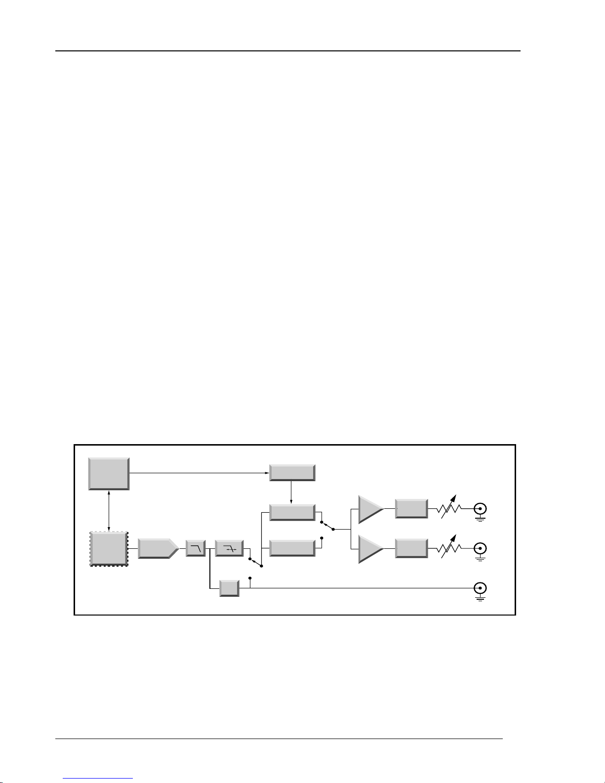
DDS with Advanced Signal Processing
A block diagram for the DS360 is shown in Figure 1. The DS360 utilizes direct digital
synthesis to generate its basic waveform. A Motorola DSP56002 advanced 24 bit digital
signal processor (DSP) acts as the phase accumulator and contains the internal waveform
RAM. The DSP chip gives the DS360 exceptional flexibility for generation of different
waveforms. A 32.333 MHz, 25 PPM crystal provides all clocking information for the
DS360, giving it exceptional frequency stability.
The DSP waveform RAM feeds an ultra low distortion 20 bit DAC, which is followed by
th
a 7
order Cauer anti-imaging filter to accurately reconstruct the sampled waveforms.
For sinewave generation, this is followed by a distortion reduction filter, that removes
nearly all of the remaining distortion components of the waveform. The output of this
filter passes through the fine amplitude control and to the low distortion balanced /
unbalanced power amplifier. The power amplifier is capable of generating a 40 Vpp
sinewave, with about -100dB of distortion in the unbalanced configuration and superior
performance at lower amplitudes. Finally the signal passes through output attenuators,
capable of 0, -20, -40 or -60 dB of attenuation.
Other waveforms follow slightly different paths. White noise skips the distortion
reduction filters, while pink noise adds the pink noise filter. Squarewaves and the
waveform sync signal are generated by discriminating the function with a high speed
comparitor. Burst signals are generated by passing any of the waveforms through the
burst DACs.
Main CPU
Display
Keys
Interfaces
56002
DSP Chip
Burst Control
20 bit D/A
Anti
Imaging
Filter
Distortion
Reduction
Filters
Comparator
Sine
Square
Logic
Burst Level
Fine Amplitude
Control
Burst
Normal
Power
Amplifier
+
_
Course
Attenuators
Attenuator
Attenuator
Source
Resistors
+
_
Sync
Figure 2-1 DS360 Block Diagram
DS360 Ultra Low Distortion Function Generator
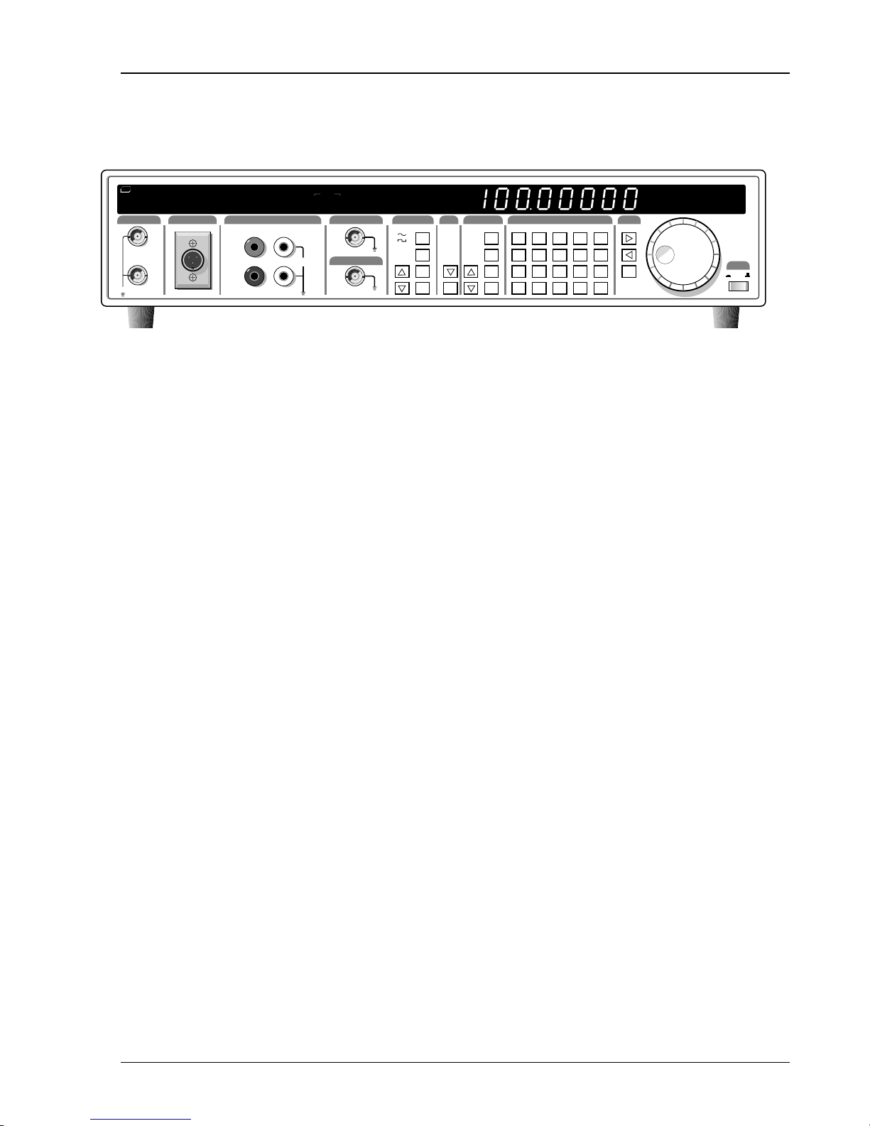
Basics 2-5
Front Panel Features
SRS
STANFORD RESEARCH SYSTEMS
MODEL DS360 ULTRA LOW DISTORTION FUNCTION GENERATOR
BNC OUTPUT
40V max.
XLR OUTPUT
+
–
JACK OUTPUT
+
–
COMMON
40 VDC MAX.
GROUND
STATUS
REM SRQ
ACT ERR
OUTPUT
TRIG'D
SYNC OUT
TRIGGER/GATE IN
TRIGGER
IMPEDANCE
ON
OFF
INT
50
EXT
150
SINGLE
600
GATE
HI Z
FUNCTION
WHT NOISE
TTL
PINK NOISE
2-TONE
TTL
ON/OFF
OFFSET
AMPL
FREQ
STP/BWSTR/C
REL
TONE 2TONE1
DEPTH
TRIGRCOUNT
RATE
OUTPUT
SECONDARY MODIFYENTRY
SWP/BURST
SHIFT
FREQ
AMPL
OFFST
DIGITAL
ON/OFF
LOG SWP
BAL
BURST
TRIG SRC
BW NOISE
START
CENTER
DEPTH
STOP
BW
BURST CNT
TRIGR
RATE
LIN SWP
UNBAL
50 150 600
SHIFT STO RCL CLR
F STEP F STEP ENA DIG FREQ # BITS
7
+/-
GPIB RS232
.
4
T2 MODE
T1/T2
0
1
DIG MODE
8
9
CAL SRQ
5
6
DIG 1 DIG 2 DIG 3
2
3
HI Z
Vrms
%
Vpp/DC
dB
DIG 0
dBm
kHz
dBV
Hz
LOCAL
DISP REL
Hz dB
Vp-p
kHz dBV
VDC
% dBm
Vrms
REL
POWER
ON/STBY
Figure 2-2 Front Panel
Power Switch
The power for the DS360 is turned on by depressing the power button. After turning the
power on the LED display will display the units serial number for about 2 seconds,
perform the internal self tests and begin operation.
Caution
This instrument may be damaged if operated with the LINE VOLTAGE SELECTOR set
for the wrong AC line voltage or if the wrong fuse is installed.
Reset
Spin Knob
Turn on the power while holding down the clear [CLR] key and continue to hold it for at
least 2 seconds to reset the unit. The unit will perform power on tests and assume the
default settings. Any stored settings will be lost.
The spin knob is used to modify the parameter currently displayed on the DS360 display.
The flashing digit indicates which digit is being incremented. The knob will modify all
numeric parameters, as well as parameters which have a list of choices.
DS360 Ultra Low Distortion Function Generator
2-6 Basics
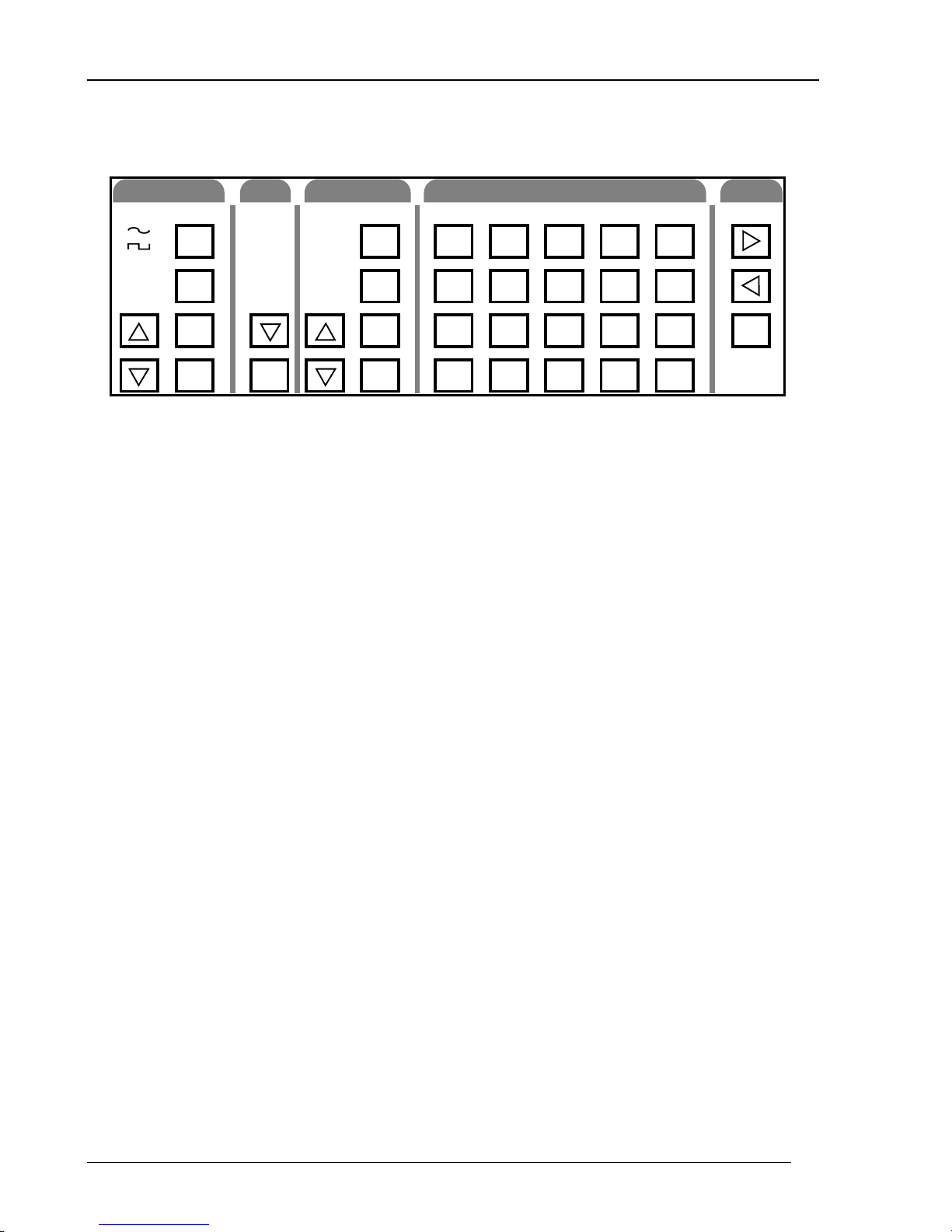
Keypad
FUNCTION
WHT NOISE
PINK NOISE
2-TONE
FREQ
AMPL
OFFST
ON/OFF
OUTPUT
UNBAL
BAL
DIGITAL
(SHIFT)
TRIGR
Function Keys
These keys control the main function output. The [∧] up and [∨] down function keys
select between the main output functions. [FREQ], [AMPL] and [OFFST] select the
output frequency, amplitude and DC offset voltage. [ON/OFF] turns the output on and
off.
Output Selection Key
SECONDARY MODIFYENTRY
SHIFT
SHIFT STO RCL CLR
F STEP F STEP ENA DIG FREQ # BITS
+/-
GPIB RS232 CAL SRQ
.
T2 MODE
0
50 150 600
7
4
T1/T2
1
LIN SWP
LOG SWP
BURST
BW NOISE
SWP/BURST
ON/OFF
TRIG SRC
START
CENTER
DEPTH
STOP
BW
BURST CNT
RATE
Figure 2-3 Keypad
HI Z
Vrms
%
DIG MODE
8
5
DIG 1 DIG 2 DIG 3
2
Vpp/DC
9
6
3
dB
DIG 0
dBm
kHz
dBV
Hz
LOCAL
DISP REL
REL
The [∨] key changes the output configuration from one of the three choices: unbalanced,
balanced and digital. Pressing the [∨] once moves one entry down the list; pressing the
[SHIFT](∧) moves one entry up the list.
Trigger Key
The [TRIGR] key begins singly triggered modified functions, like single sweeps or
bursts.
Modify Function Keys
These keys control the function output modification commands for sweeps, bursts or
bandwidth limited noise. The [∧] up arrow and [∨] down arrow keys select the
modification type. The [SWP/BURST] key turns the modification function on and off.
The other keys select different function modification parameters (start frequency, burst
depth).
Only modify functions that are allowable for the current function type (sine, square,
noise...) can be selected (i.e. sweep can be selected for sine or square, but not white
noise). Only modify parameters (START FREQ, STOP FREQ ...) that are valid for the
selected modify function can be changed. If a currently invalid modify parameter is
selected, the unit will beep and display “not APPL” (not applicable). If a function type
DS360 Ultra Low Distortion Function Generator

Basics 2-7
change causes the currently displayed modify function to become invalid, the display
will revert to the frequency [FREQ] display.
Shift Key
The [SHIFT] key is used to select functions printed above the keys. Press the [SHIFT]
followed by the [function] key to select the desired function. When the shift key is
pressed, the shift LED will light. This indicates that the keypad is in “shifted” mode.
Pressing [SHIFT] a second time will deactivate shift mode. Note that in the manual,
whenever [SHIFT] is indicated, the desired function is printed above the key, not on
the key itself.
Numeric Keys
The numeric keypad allows for direct entry of the DS360’s parameters. To change a
parameter value, type the new value, followed by one of the [units] keys. A typing error
may be corrected by pressing the [CLR] key, which recalls the old value. The [+/-] key
may be selected at any time during numeric entry.
Units Keys
Cursor Keys
Rel Key
The units are used to terminate numeric entries. Press the key with the desired units to
enter the typed value. Some parameters have no particular units and any of the units keys
may be used. When the amplitude is displayed, pressing one of the units keys will cause
the display to change the units to the type pressed. This means that the amplitude display
can changed from Vpp, Vrms, dBm and dBV without entering a new value.
The [>] cursor right and [<] cursor left keys move the flashing digit to the right and left
of the display. They also switch between parameters which have a list of choices.
The [REL] key changes the amplitude display to the relative display mode. The
amplitude is displayed in dB relative to the value when [REL] was pressed. Pressing
[REL] a second time changes the amplitude display back to normal. Pressing
[SHIFT][REL] shows the Vpp amplitude that the display is rel’d to.
DS360 Ultra Low Distortion Function Generator
2-8 Basics
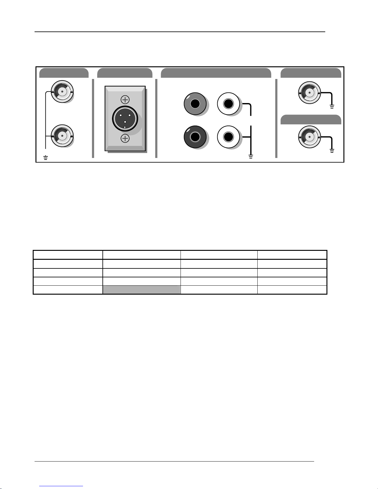
Outputs
BNC OUTPUT
XLR OUTPUT
JACK OUTPUT
+
+
–
40V max.
Function Output
The three output types are connected in parallel. There are three separate sets of output
connectors: BNC, XLR and banana plugs. The different output signals are the positive
output, negative output, common and chassis ground. The connectors are configured as
listed below.
Function Output Connections
Output Signal BNC Connection XLR Connection Banana Plug
Positive Output
Negative Output
Common Both BNC Shields Pin 1 Common (black) jack
Ground Pin 4 Ground (green) jack
+ BNC Center contact
- BNC Center contact
–
Figure 2-4 Outputs
Pin 2 + (red) jack
Pin 3 - (white) jack
COMMON
40 VDC MAX.
GROUND
TRIGGER/GATE IN
SYNC OUT
TTL
TTL
The positive and negative outputs are both referenced to the common, which may be
floated +/-40 V
DC
selectable. If the output is terminated into an incorrect impedance the output amplitude
will be incorrect and may exhibit increased distortion.
Sync Output BNC
This output is a squarewave synchronized to the main function output. Its shield is
connected to chassis ground and cannot be floated.
Trigger / Gate In BNC
A low to high TTL signal on this input begins externally triggered bursts and sweeps.
For gated output, a TTL high gates the output on and a TTL low gates the output off. The
BNC shield is connected to chassis ground and cannot be floated.
DS360 Ultra Low Distortion Function Generator
from the chassis ground. The output impedance of the outputs is

Basics 2-9
Indicators
STATUS
REM SRQ
ACT ERR
OUTPUT
ON
OFF
TRIG'D
IMPEDANCE
50
150
600
HI Z
TRIGGER
INT
EXT
SINGLE
GATE
FREQ
AMPL
STP/BWSTR/C
TONE 2TONE1
TRIGRCOUNT
OFFSET
REL
DEPTH
RATE
Figure 2-5 Indicator LED’s
Status LEDs
These 4 LEDs indicate the DS360’s status.
Status LEDs
Name Function
REM
The DS360 is in GPIB remote status. The [>] cursor right key returns local control.
SRQ The DS360 has requested service on the GPIB.
ACT Flashes for RS232 or GPIB activity.
ERR Flashes on error in a command.
Configuration LEDs
These LEDs indicate the output configuration, source impedance and triggering mode of
the DS360.
Configuration LEDs
Heading Display LED Parameter
OUTPUT ON
OFF
TRIG’D
IMPEDANCE 50
150
600
Hi-Z
TRIGGER INT
EXT
SINGLE
GATE
Output On
Output Off
Sweep or Burst Triggered
50 Ω Output Impedance
150 Ω Output Impedance
600 Ω Output Impedance
Hi-Z Output Impedance
Internal Trigger for Sweeps or bursts
External Trigger for Sweeps or Bursts
Single Trigger for Sweeps or Bursts
External Gate for Bursts only
DS360 Ultra Low Distortion Function Generator

2-10 Basics
Parameter LEDs
These LEDs indicate which parameter is currently displayed in the parameter display.
Parameter LEDs
Display LED Parameter
FREQ Output Frequency
AMPL Output Amplitude
OFFSET Output Offset
STARTF Start Frequency for Sweeps
Center Frequency for Bandwidth Limited Noise
STOPF Stop Frequency for Sweeps
Cutoff Frequency for Bandwidth Limited Noise
REL Indicates that the amplitude display is in REL mode. Does not indicate a specific
display.
TONE1 Indicates that Amplitude and Frequency Displays refer to TONE 1. Does not
indicate a specific display.
TONE2 Indicates that Amplitude and Frequency Displays refer to TONE 2. Does not
indicate a specific display.
DEPTH Off Level Depth for Bursts
COUNT Burst Count for Bursts
TRIGR Trigger Source for Sweeps and Bursts
RATE Burst Rate for Bursts
DS360 Ultra Low Distortion Function Generator