

Page 1

Operation and Service Manual
Precision DC Voltage Source
DC205
Stanford Research Systems
Revision 0.30 • February 22, 2019
Page 2

Certification
Stanford Research Systems certifies that this product met its published specifications at the time
of shipment.
Warranty
This Stanford Research Systems product is warranted against defects in materials and workmanship for a period of one (1) year from the date of shipment.
Service
For warranty service or repair, this product must be returned to a Stanford Research Systems
authorized service facility. Contact Stanford Research Systems or an authorized representative
before returning this product for repair.
Information in this document is subject to change without notice.
Copyrightc Stanford Research Systems, Inc., 2019. All rights reserved.
Stanford Research Systems, Inc.
1290–D Reamwood Avenue
Sunnyvale, CA 94089 USA
Phone: (408) 744-9040 • Fax: (408) 744-9049
www.thinkSRS.com • e-mail: info@thinkSRS.com
Printed in U.S.A. Document number 9-01745-903
DC205 Precision DC Voltage Source
Page 3

Contents
General Information iii
Safety and Preparation for Use ................ iii
Symbols ............................. iv
Notation ............................. v
Specifications .......................... vi
1 Getting Started 1 – 1
1.1 How to use this manual ................. 1–2
1.2 Preliminaries ........................ 1–2
1.2.1 Equipment needed ................ 1–2
1.3 First example: turning on the instrument ....... 1–2
1.4 User interface ....................... 1–4
1.5 Instrument settings .................... 1–5
1.5.1 Sense ........................ 1–5
1.5.2 Isolation ...................... 1–6
1.5.3 Scanning ...................... 1–7
1.6 Interlock .......................... 1–10
2 Operation 2 – 1
2.1 Navigating the front panel ................ 2–2
2.1.1 Power ....................... 2–2
2.1.2 Range ....................... 2–4
2.1.3 Select / Adjust ................... 2–4
2.1.4 Numeric Entry .................. 2–5
2.1.5 Sense ........................ 2–6
2.1.6 Config ....................... 2–6
2.1.7 Scan ........................ 2–7
2.1.8 Output ....................... 2–7
2.1.9 Status ........................ 2–8
2.1.10 Source Out ..................... 2–8
2.2 Theory of operation .................... 2–10
2.3 Scanning .......................... 2–10
2.4 Error messages ...................... 2–10
3 Remote Operation 3 – 1
3.1 Index of commands .................... 3–2
3.2 Alphabetic list of commands ............... 3–4
i
Page 4

ii Contents
3.3 Introduction ........................ 3–6
3.3.1 Interface configuration .............. 3–6
3.3.2 Buffers ....................... 3–6
3.4 Commands ......................... 3–7
3.4.1 Command syntax ................. 3–7
3.4.2 Notation ...................... 3–8
3.4.3 Examples ..................... 3–8
3.4.4 Configuration commands ............ 3–9
3.4.5 Setting commands ................ 3–10
3.4.6 Scan commands .................. 3–10
3.4.7 Setup commands ................. 3–13
3.4.8 Interface commands ............... 3–13
3.4.9 Status commands ................. 3–15
3.5 Status model ........................ 3–18
3.5.1 Status byte (SB) .................. 3–18
3.5.2 Service request enable (SRE) .......... 3–19
3.5.3 Standard event status (ESR) ........... 3–19
4 Field Calibration 4 – 1
4.1 Introduction to Field Calibration ............ 4–2
4.2 Equipment needed .................... 4–2
4.3 Detailed procedure .................... 4–2
A Fuse and ac Line A – 1
A.1 Power Entry module ................... A–1
A.2 ac voltage selector ..................... A–1
A.3 Fuse installation ...................... A–3
DC205 Precision DC Voltage Source
Page 5

General Information
Safety and Preparation for Use
WARNING
AC line voltage
CAUTION
Line cord
Dangerous voltages, capable of causing injury or death, are
present in this instrument. Do not remove the product covers
or panels. Do not apply power or operate the product without
all covers and panels in place.
The DC205 Precision DC Voltage Source operates from a 100 V, 120 V,
220 V–230 V, or 240 V nominal ac power source having a line frequency of 50 Hz or 60 Hz. Before connecting the power cord to a
power source, verify that the LINE VOLTAGE SELECTOR, located
in the rear panel power-entry module, is set so that the correct ac line
voltage value is visible. For operation with 230 V ac power, the LINE
VOLTAGE SELECTOR should be set to 220 V.
The DC205 Precision DC Voltage Source will be damaged if operated with the LINE VOLTAGE SELECTOR set for the wrong ac line
voltage, or if the wrong fuses are installed. Verify that the correct
line fuses are installed before connecting the line cord. Use two (2)
metric size 5 ×20 mm fuses. For 100 V/120 V, use 1 A fuses; for 220 V–
230 V/240 V, use 0.5 A fuses. See appendix A for detailed instructions.
Service
The DC205 Precision DC Voltage Source has a detachable, three-wire
power cord for connection to the power source and to a protective
ground. The chassis of the instrument is connected to the outlet
ground to protect against electrical shock. Always use an outlet
which has a properly connected protective ground.
The DC205 Precision DC Voltage Source does not have any user
serviceable parts inside. Refer service to a qualified technician.
Do not install substitute parts or perform any unauthorized modifications to this instrument. Contact the factory for instructions on
how to return the instrument for authorized service and adjustment.
iii
Page 6
iv General Information
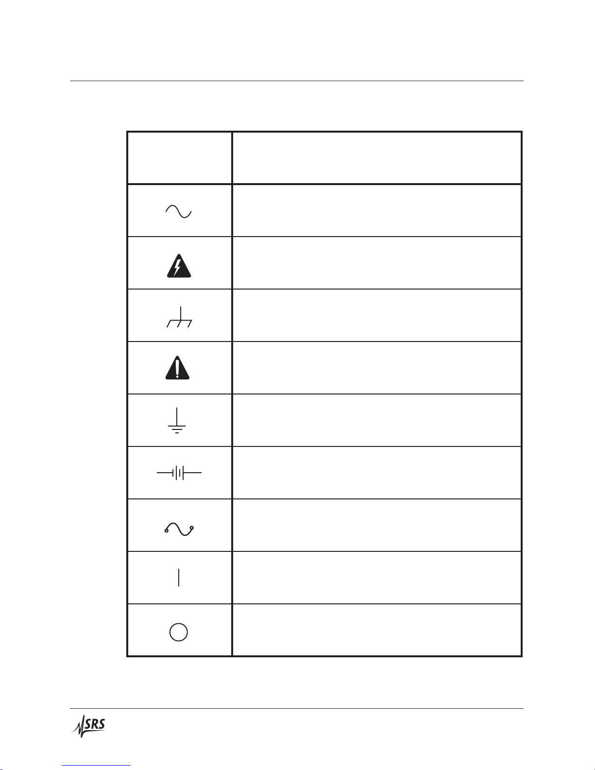
Symbols you may Find on SRS Products
Symbol Description
Alternating current
Caution - risk of electric shock
Frame or chassis terminal
Caution - refer to accompanying documents
Earth (ground) terminal
Battery
Fuse
On (supply)
Off (supply)
DC205 Precision DC Voltage Source
Page 7

General Information v
Notation
The following notation will be used throughout this manual.
WARNING
CAUTION
A warning means that injury or death is possible if the instructions
are not obeyed.
A caution means that damage to the instrument or other equipment
is possible.
Typesetting conventions used in this manual are:
• Front-panel buttons are set as [Button]
Knob
• Front-panel knobs are set as
• Front-panel indicators are set as Overload
• Remote command names are set as *IDN?
• Literal text other than command names is set as OFF
Remote command examples will all be set in monospaced font. In
these examples, data sent by the host computer to the DC205 are set
as straight teletype font, while responses received by the host
computer from the DC205 are set as slanted teletype font.
DC205 Precision DC Voltage Source
Page 8

vi General Information
Specifications
All performance specifications after 2 hour warm-up at 23◦C ±1◦C
ambient, unless otherwise specified.
Output
Accuracy and stability
Range
Full Resolution Max Time Settling
scale (1 ppm) current const.
†
V μV mA μs ms
1V ±1.010 000 1 50 160 50
10 V
100 V
±10.100 00 10 50 160 50
±101.000 0 100 25 400 100
†
Time required to settle to 63 % of final value
‡
Time to settle to 99.999 % of final value
Settling times measured for full-scale step into 10 MΩ load.
Range
Accuracy Stability
(23◦C ±5◦C) (±1◦C)
24 h 90 day∗1 year
∗
24 h
±( ppm setting + μV)
1V 7 + 2 12 + 6 25 + 10 1 + 1
10 V
100 V
7 + 6 12 + 15 25 + 20 1 + 3
8 + 60 12 + 80 25 + 100 1 + 20
∗
preliminary
time
‡
Noise and drift
Range
Temperature Noise
coefficient (typical)
0◦C–40◦C (0.1 – 10) Hz 10 Hz – 100 kHz
±( ppm setting + μV)/◦C μVrms
1V 1 + 1 0.5 9
10 V
100 V
1 + 2 1.5 12
1 + 15 12 50
DC205 Precision DC Voltage Source
Page 9

General Information vii
Remote Interfaces
General
RS-232
DB-9 connector, 9600 baud
USB USB type B receptacle; serial port emulation, 115,200 baud
Optical fiber Connection to SX199 Optical Interface Controller. Provides
isolated connectivity to GPIB, RS-232, and Ethernet.
Parameter
Specification
Temperature 0◦Cto40◦C, non-condensing
Power < 20 W, 100/120/220/240 VAC, 50/60 Hz
Dimensions 8.3W × 3.5H × 13D
Weight 10 lbs
Fuse two (2) metric size 5 × 20 mm
DC205 Precision DC Voltage Source
Page 10

viii General Information
DC205 Precision DC Voltage Source
Page 11

1 Getting Started
In This Chapter
This chapter provides step-by-step instruction to get started quickly
with the DC205 Precision DC Voltage Source. Refer to chapter 2 for
a more complete introduction to the DC205.
1.1 How to use this manual ................. 1–2
1.2 Preliminaries ....................... 1–2
1.2.1 Equipment needed ................ 1–2
1.3 First example: turning on the instrument ....... 1–2
1.4 User interface ....................... 1–4
1.5 Instrument settings .................... 1–5
1.5.1 Sense ........................ 1–5
1.5.2 Isolation ...................... 1–6
1.5.3 Scanning ...................... 1–7
1.6 Interlock .......................... 1–10
1–1
Page 12

1–2 Getting Started
1.1 How to use this manual
Two possible starting points are available to new users of the DC205.
Those who want to begin with an overview to the functional layout
of the instrument should turn to Chapter 2.
Users who prefer to jump in and begin using the DC205 first should
continue with this Chapter, where a series of step-by-step procedures
are given to verify the basic performance of the instrument. This will
also providea quick introductionto the DC205and how it isoperated.
Chapter 3 discusses remote operation of the DC205 over any of the
three remote interfaces: USB, RS-232, and optical fiber.
1.2 Preliminaries
The following sections provide step-by-step instructions for verifying the basic operation of the DC205. In addition to confirming
proper operation, it provides a good introduction to operating the
current source.
1.2.1 Equipment needed
To perform all the steps described in this chapter, you will need:
1. a collection of stacking banana plug test leads,
2. a precision voltmeter with at least 6 digits resolution,
3. a BNC 50 Ω terminator,
4. a dual banana-to-BNC (banana-male, BNC-female) adapter.
1.3 First example: turning on the instrument
This section describes the initial steps for first operating the DC205.
Please pay specific attention to the AC line voltage selector setting.
1. Before using the instrument, verify the rear-panel power entry
module is properly configured for the power line voltage in
CAUTION
your region. Applying power with improper setting of the
line voltage selector will result in significant damage to the
DC205.
2. Plug the AC line cord into the rear-panel power entry module,
and then into a grounded wall outlet.
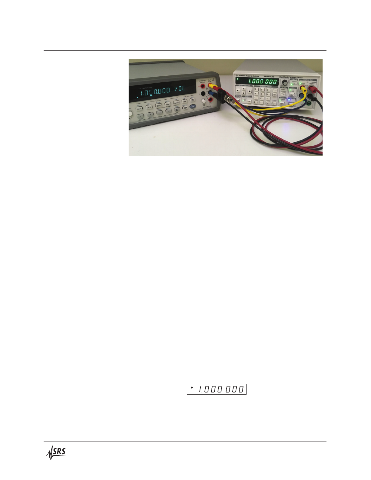
3. Using banana-plug test leads, connect the DC205 OUTPUT
terminals (HI and LO) to the voltmeter input terminals (HI and
LO). Turn on the voltmeter and set it to DCV, Autorange.
DC205 Precision DC Voltage Source
Page 13

1.3 First example: turning on the instrument 1–3
4. Restore the factory default settings by pressing the POWER [ ]
while holding the BACKSPACE [
] button depressed. This
will perform the power-on reset, clear any field calibration
data, and return the instrument to its factory default state.
After several seconds, the display will show
and then
.
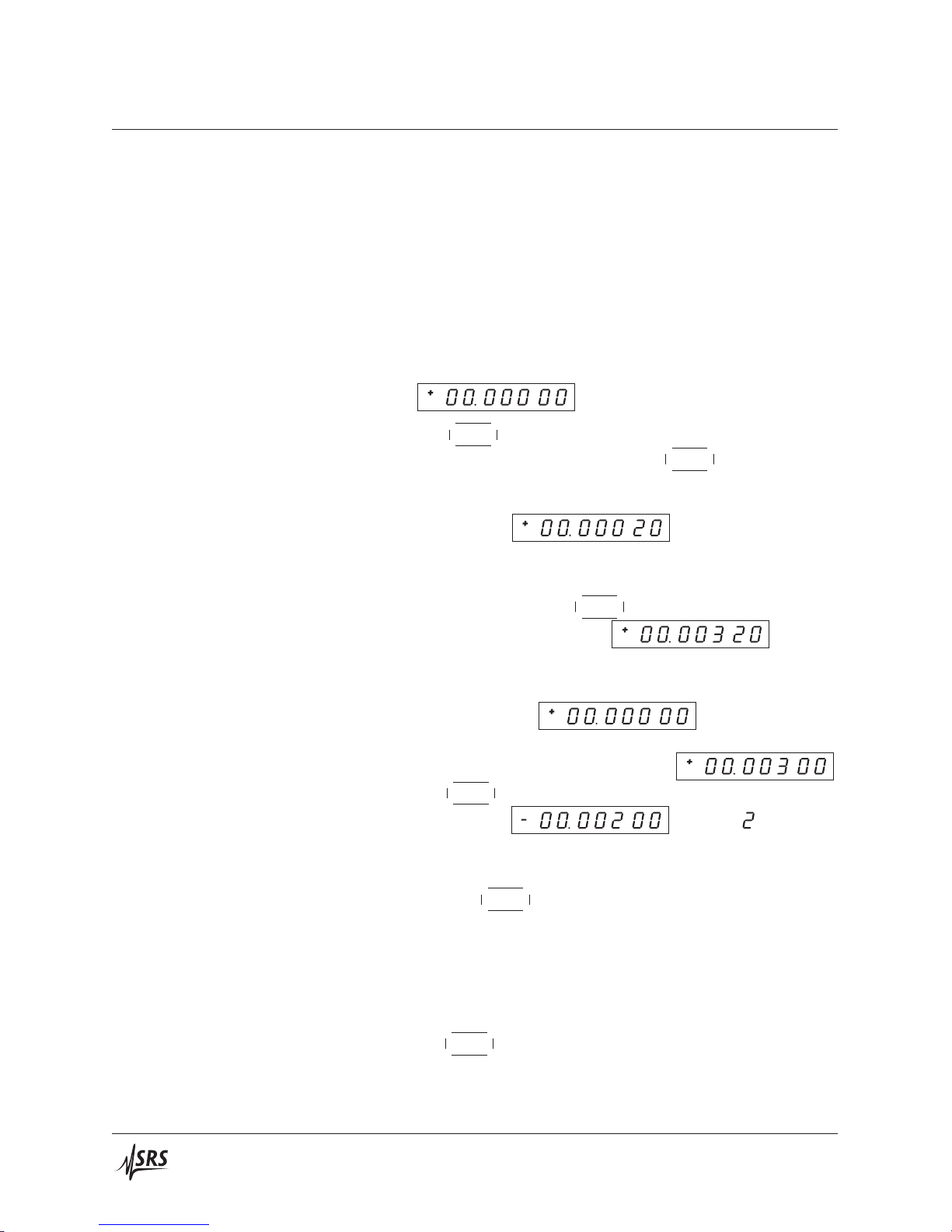
5. Key in the value 1.000000 V. Start by pressing the [1] and notice the display shows the polarity indicator + and digit 1 are
shown. Also, the Pending indicator begins blinking, indicating
the numeric value is awaiting entry.
6. Try pressing another digit, such as [3]. Note the value is not
added to the display, as the implied value (13) is out of range
for the current setting. Then press the decimal point button,
[.], and then press [0] three times. The display should show
and Pending should still be flashing.
7. Now press the [7] digit. The display will show
. We don’t actually want that last digit, so
now press the [
] button to erase the .
8. Press the [Enter/Start]. The Pending indicator should go dark,
and the display now shows
. The multi-
meter should not yet show any steady reading.
9. Finally, press the OUTPUT [On/Off] button. The On indicator should illuminate, and the multimeter should now show a
reading very close to +1.00000 V.
,
DC205 Precision DC Voltage Source
10. Allow the unit to warm up for 2 hour for full specified performance. Warm up is not needed to test basic functionality.
Page 14
1–4 Getting Started
1.4 User interface
This section explores the DC205 front-panel interface, and demonstrates the different methods for entering or modifying the voltage
setting.
1. If the OUTPUT is still On, turn it off by pressing the [On/Off]
button.
2. Change the RANGE to ±10V by pressing [Range] once. Set
the voltage to 0 by pressing [0] and then [Enter/Start]. Enable
the output by pressing OUTPUT [On/Off]. The display should
show
knob inwards. The least significant digit should
3. Press the
begin to blink. Now slowly turn the
.
knob clockwise. The
DC205 should click, and the least significant digit (tens of microvolts) begin incrementing. Continue turning the knob until
the display shows
4. Press the SELECT/ADJUST [] button two times. Notice that
with each press, the blinking digit moves one position to the
left. Now slowly turn the
The display should now show
knob for 3 more clicks clockwise.
, and the
multimeter should show the same voltage.
5. Now clear the output setting by pressing [0] and [Enter/Start].
The display returns to
, but notice the mil-
livolts digit is still blinking. Now press the [] button three
times. The display should now show
Turn the
should now show
knob counterclockwise for 5 clicks. The display
. and the (millivolts
position) is still blinking.
.
6. Press the [Cancel] button—now the blinking should stop. Carefully turn the
knob clockwise without depressing the shaft.
Note that there no clicks, and the setting does not change.
This brief exercise demonstrated the entry modes for the DC205, including the notion of active editing (indicated by the blinking digit),
and the use of the [Cancel] button to return to the display-idle state.
Note that the [] and [] buttons provide essentially the same func-
tionality as the
knob .
DC205 Precision DC Voltage Source
Page 15

1.5 Instrument settings 1–5
1.5 Instrument settings
This section will demonstrate the basic configurations of the DC205.
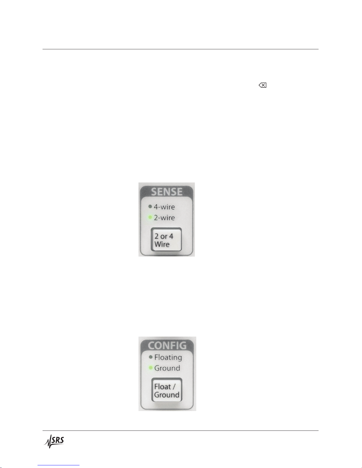
1.5.1 Sense
The SENSE setting selects 2-wire or 4-wire (remote sensing) for the
voltage source circuitry.
1. If the OUTPUT On indicator is lit, disable the DC205 OUTPUT
by pressing the [On/Off] button.
2. Connect a pair of banana test leads from the red and black
SENSE terminals on the DC205 to the input HI, LOW terminals
on the multimeter.
3. Connect a second pair of banana test leads from the red and
black OUTPUT terminals on the DC205, connecting the other
end of these test leads to the back of the corresponding stackable sockets on the banana leads at the multimeter. Be sure to
connect HI to HI, and LOW to LOW.
4. Plug the banana-to-BNC adapter into the back banana leads at
the multimeter. Be sure to align the Ground tab of the adapter
with the LOW side banana leads.
5. If not already so configured, press the [Range] button repeatedly until the ±1V range is selected. Press [Float/Ground] to
select Ground, and press [2 or 4 Wire] to select 2-wire.
6. Press [1] and [Enter/Start] to program the setting to 1.000 000 V.
Press [On/Off] to enable the output. Verify the multimeter
displays a voltage very close to 1.000 000 V.
knob to adjust the
7. Use the SELECT/ADJUST buttons or the
DC205 until the multimeter displays exactly 1.000 000 V, with a
minimum of 100 μV resolution.
8. Attach the 50 Ω BNC terminator to the banana-to-BNC adaptor.
Verify that the multimeter display drops by at least one or two
millivolts (the actual drop will depend on the length and wire
gauge of your banana test leads).
9. Now, press the [2 or 4 Wire] button. Verify that the 4-Wire
indicator and the SENSE indicator both become illuminated.
10. The multimeter should again be displaying exactly 1.000 000 V,
with a minimum of 100 μV resolution.
DC205 Precision DC Voltage Source
Page 16
1–6 Getting Started
This exercise demonstrated the function of remote sensing in the
DC205. When operated in simple 2-wire mode, the commanded
output voltage is controlled internally. When a significant load is
presented (in this case, 50 Ω), a current flows from the voltage source
through the circuit created by the output leads. In this case, with
1 V across 50 Ω, a total of 20 mA flows through the output relays and
the banana test leads. Even 10 mΩ of lead resistance in this case will
lead to a 200 μV potential drop.
1.5.2 Isolation
By enabling remote sensing in the 4-Wire mode, the DC205 controls
the potential as measured by the sense leads. By carefully arranging
the SENSE wiring to not carry any of the load current, the desired
output voltage is applied at the point of interest (in this case, at the
multimeter input terminals).
The CONFIG setting selects whether the output circuitry of the
DC205 is referenced to chassis ground or floating.
1. If the OUTPUT On indicator is lit, disable it by pressing the
[On/Off] button.
2. Connect a pair of banana test leads from the red and black OUTPUT terminals on the DC205 to the input HI, LOW terminals
on the multimeter.
3. Press the [Range] buttonto select ±1V. Press the[Float/Ground]
button to select Floating. Press [1] and then [Enter/Start] to set
the display to
.
4. Press the [On/Off] button to enable the output. Verify that
+1.0000 V appears on the multimeter.
5. Connect another banana test lead to the green chassis ground
terminal on the DC205 front panel. Connect the second end of
DC205 Precision DC Voltage Source
Page 17

1.5 Instrument settings 1–7
the test lead to the back of the red HI banana lead at the DC205.
Notice that the multimeter still displays +1.0000 V, even though
the HI terminal is now connected to chassis ground. The output of the DC205 is configured to float; by grounding the HI
terminal with the banana lead, the LOW terminal is now at
−1.0000 V with respect to ground.
6. Now press the [Float/Ground] button to select Ground.
Now notice that the multimeter display had dropped to a value
near 0 V (probably a few millivolts). Also, the red Overload
indicator on the DC205 is illuminated. With the DC205 in
Ground mode, the LOW terminal is internally tied to ground.
By grounding the HI terminal to with the third banana lead, we
are shorting the output. This causes the Overload to illuminate.
7. Carefully remove the third banana lead from the back of the
banana cable at the HI terminal. The Overload indicator should
turn off, and the multimeter again should display very close to
1.0000 V.
1.5.3 Scanning
In addition to generating a stable DC voltage, the DC205 is also able
to create linear sweeps of the output voltage. This example will
demonstrate one such sweep.
1. If the OUTPUT On indicator is lit, disable it by pressing the
[On/Off] button.
2. Connect a pair of banana test leads from the red and black OUTPUT terminals on the DC205 to the input HI, LOW terminals
on the multimeter.
3. Press the [Range] buttonto select ±1V. Press the[Float/Ground]
button to select Ground. Press the [2 or 4 Wire] button to select
2-wire.
4. Briefly press the [Setup Arm] button, entering the SCAN setup
mode. The display should now show
changing the display to
scan range selection to
. Press [] once.
. Press [] to return the
. Press [],
5. The display now shows the beginning voltage for the scan,
indicated with the
at the left side of the display. Key in
the value [0], [.], [1], and then press [Enter/Start]. The display
DC205 Precision DC Voltage Source
should show
. Press [] again.
Page 18

1–8 Getting Started
6. The display now shows the ending voltage for the scan, indicated with the
at the left side of the display. Key in the value
[0], [.], [8], and press [Enter/Start]. The display should now
show
. Press [] again.
7. The display now shows the time duration for the scan, indicated by the
at the left side of the display. Key in the value
[1] [0] and press [Enter/Start], to set the scan to 10 seconds. The
display should now show
. Press [] again.
8. The display now shows the scan shape setting, indicated
by the
choices are
at the left side of the display. The two
(a unidirectional ramp), and
(a bidirectional ramp). Press [] and
[] to switch between these options. Leave the setting
at
, and then press [] again.
9. The display now shows the scan repeat mode, indicated by
the
are
at the left side of the display. The two choices
(a single scan) and
(repeating until cancelled). Press [] and [] to switch between
these options. Leave the setting at
, and
then press [] again.
10. The display now shows the scan display mode, indicated by
the
at the left side of the display. The two choices are
(display is updated in near realtime during
the scan) and
(display is left static during the
scan). Press [] and [] to switch between these options. Leave
the setting at
11. The display will be back to the
to navigate backwards, to the
, and then press [] again.
setting. Pressthe []
setting. You can
navigate forward and backward through the scan parameters
with the [] and [] select buttons. Note, however, that if the
scan range is modified, then both the beginning and ending
scan voltages are reset to zero.
Press [Cancel] to exit SCAN setup mode. Set the output voltage to 0.5 V by pressing [0], [.], [5], [Enter/Start]. Then turn
the output On by pressing [On/Off]. The multimeter should
display a value close to 0.5000 V.
12. Now press and hold the [Setup Arm] button for at least 3 sec-
DC205 Precision DC Voltage Source
Page 19

1.5 Instrument settings 1–9
onds. The display will briefly show , and
then show
, which is the starting voltage
for the scan. Also, the Armed indicator comes on to show
that the scan is armed and ready, and the Pending indicator is
steadily illuminated. Press the [Enter/Start] button to start the
scan.
13. While the scan is running, notice that the multimeter and the
DC205 display are both smoothly sweeping from 0.1 V to 0.8 V.
After 10 seconds, the scan should end and the output voltage
settles at 0.8 V.
DC205 Precision DC Voltage Source
Page 20

1–10 Getting Started
1.6 Interlock
The DC205 is designed with a safety interlock circuit that must
be definitively activated for the ±100 V output range to be en-
WARNING
abled. The interlock is intended to support safe operation of
this instrument in a test system. Bypassing the interlock can
lead to a hazardous condition, possibly exposing the operator
to dangerous electrical potentials up to ±100 V, capable of causing injury or death.
Figure 1.1: The DC205 rear panel, shown with an interlock defeat plug.
For safety, the ±100 V range can only be enabled when the interlock
signal is asserted. To assert the interlock, a low impedance circuit
must be closed between pins 1 and 2 of the rear-panel INTERLOCK
socket. A mating plug is provided with the DC205.
When the interlockis asserted, the front panel Interlock indicator will
be illuminated. The interlock must be asserted to enable OUTPUT
On when the RANGE is ±100 V.
Note that the ±1V and ±10 V range settings can be enabled independent of the whether the interlock is asserted.
DC205 Precision DC Voltage Source
Page 21

2 Operation
In This Chapter
This chapter provides a basic overview of the DC205 Precision DC
Voltage Source.
2.1 Navigating the front panel ............... 2–2
2.1.1 Power ....................... 2–2
2.1.2 Range ....................... 2–4
2.1.3 Select / Adjust ................... 2–4
2.1.4 Numeric Entry .................. 2–5
2.1.5 Sense ........................ 2–6
2.1.6 Config ....................... 2–6
2.1.7 Scan ........................ 2–7
2.1.8 Output ....................... 2–7
2.1.9 Status ........................ 2–8
2.1.10 Source Out ..................... 2–8
2.2 Theory of operation ................... 2–10
2.3 Scanning .......................... 2–10
2.4 Error messages ...................... 2–10
2–1
Page 22

2–2 Operation
2.1 Navigating the front panel
The front panel of the DC205 is organized into distinct functional
sections. A picture of the entire front panel is in Figure 2.1, below.
2.1.1 Power
Figure 2.1: The DC205 front panel.
When the DC205 is connected to an AC power source, the power
supply will initially be in standby mode, indicated by the Standby
indicator in the POWER section. To turn the DC205 on, press and
hold the [
] button until Standby is no longer lit, and the rest of the
display comes on.
There are several special power-on modes accessable by holding a
second button depressed while pressing [
].
DC205 Precision DC Voltage Source
Page 23

2.1 Navigating the front panel 2–3
Stanford Research Systems Model DC205 Precision DC Voltage Source
STATUS SOURCE OUT
SELECT / ADJUST
POWER
Standby ±100 V
RANGE
±10 V
±1 V
Range
NUMERIC ENTRY
789
456
123
0
. +
/
–
Cancel
Enter /
Start
V
push to adj.
SCAN
Armed
hold to arm
Setup
Arm
CONFIG
Floating
GroundPending
Float /
Ground
Remote
Error
Interlock
SENSE
4-wire
2-wire
2 or 4
Wire
OUTPUT
On
On /
O
120 V
max
Floating
Overload
!
OUTPUTSENSE
2 V
max
HI
120 V
max
LO
2 V
max
250 V
max
Power /
Identify Field
Standby
2.1.1.1 Power-on factory reset
Pressing and holding the Input [
will restore the factory default configuration of the DC205. In addition to putting the instrument into the default configuration (see
*RST), this will also erase any saved field calibration data, and reset
the communications settings to factory defaults.
2.1.1.2 Communcations settings
Pressing andholding the [Setup/Arm] buttonwhile turning on power
will place the instrument in Communcations Configuration mode.
Here, you can set the default (power-on) baud rate for the DB-9
RS-232 port and the USB comm port.
2.1.1.3 Field calibration
Cal
Factory
Reset
Comm.
Settings
Figure 2.2: Power-on special modes on the DC205 front panel.
] button while turning on power
2.1.1.4 Power-on identification
DC205 Precision DC Voltage Source
Pressing and holding the [+/−] button while turning on power will
place the instrument in Field Calibration mode. You can read more
about this operating mode in chapter 4 (page4–1).
Pressing ahd holding the [] button while turning on power will
cause the instrument’s serial number and firmware revision number
Page 24

2–4 Operation
to be shown on the numeric display.
Initially the firmware revision will display for approximately 2 seconds, followed by the instrument’s serial number. The serial number
will remain on the display until the [Cancel] button is pressed.
2.1.2 Range
The Range button controls the DC205 output range setting. Each
press of [Range] will advance through the settings ±1V, ±10 V, and
±100 V. Pressing [Range] while in the ±100 V setting cycles back to
±1V.
2.1.3 Select / Adjust
Changing the range is only possible when the output is disabled.
Pressing [Range] while the output is On causes the Error indicator
to briefly light, and the DC205 will beep.
Note that while any range may be selected so long as the output is off,
it is not possible to enable the output onto the ±100 V range unless
the safety interlock is asserted.
The cluster of four arrow buttons in the SELECT / ADJUST block
provide a flexible interface to controlling the voltage setting of the
DC205.
When the display is in the “display-idle” state, the voltage setting
will be displayed and no digit will be blinking. Pressing any of the
DC205 Precision DC Voltage Source
Page 25

2.1 Navigating the front panel 2–5
four arrow buttons once will cause the most-recently selected digit
to begin blinking, indicating the focus for editing the setting.
Once a digit is blinking, that place value can be incremented (in a
signed sense) by pressing [], and decremented by pressing []. That
digit value can also be incremented by turning the
or decrementedby turning the
knob counterclockwise. The selected
knob clockwise,
digit place can be changed by pressing either the []or[].
The blinking function can be cancelled, and the display returned to
the display-idle state, by pressing [Cancel], or by briefly pressing the
knob inwards. When no digit is selected (blinking), turning the
knob will have no effect.
The arrow buttons are also used when navigating secondary instrument settings, such as scan parameters.
2.1.4 Numeric Entry
The numeric entry keypad is used to directly enter voltage settings
to the DC205. Values are implicitly positive unless the [+/−] button
is pressed, which will toggle the sign between positive and negative.
DC205 Precision DC Voltage Source
When entering a voltage setting through the numeric keypad, the
range limits are implicitly enforced during entry. This means, for
example, that when configured for the ±10 V range, the keypad will
not allow you to enter a value greater than 10.1 at any time.
Page 26
2–6 Operation
With the first press of either a digit key ([0] through [9]), or the
decimal point ([.]) or sign button ([+/−]), the display will switch into
numeric entry mode, with digits being added to the display as they
are pressed. To back up a single digit, use the [
] button.
While in numeric entry mode, the Pending indicator will blink. This
is to show the numeric value has not yet been set into the instrument.
Pressing the [Enter/Start] button will accept the currently displayed
value. To leave a pending numeric entry without causing the value
to be set, press the [Cancel] button.
2.1.5 Sense
The [2 or 4 Wire] button in the SENSE block controls whether the
DC205 uses local or remote feedback for controlling the voltage at
the load.
2.1.6 Config
Pressing [2 or 4 Wire] toggles between 2-wire and 4-wire. This operation can be performed at any time, regardless of the state of the
output.
The [Float/Ground] button in the CONFIG block controls whether
the output voltage LO terminal is electrically connected to chassis
ground, or isolated.
DC205 Precision DC Voltage Source
Page 27

2.1 Navigating the front panel 2–7
Pressing the [Float/Ground] button toggles between Ground (indicating the LO terminal is tied to chassis ground), and Floating (indicating the output is isolated from chassis ground. This operation
can be performed at any time, regardless of the state of the output.
2.1.7 Scan
The SCAN block of the front panel is the entry point for voltage
scanning for the DC205.
2.1.8 Output
Briefly pressing the [Setup Arm] button will bring the scan parameters onto the display. To navigate between parameters, use the []
and [] select buttons. Pressing [Cancel] will exit the parameters
mode.
Pressing and holding the [Setup Arm] button for more than 2 seconds
will attempt to arm the scan. In order to successfully arm a scan, the
output must already be on, and the instrument range must match the
scan range previously selected. Once armed, the output voltage is
changed to thebeginning scan voltage, and the Armed indicator is lit.
The Pending indicator is also lit steadily, indicating the scan is ready
and can be started by pressing the [Enter/Start] button. Pressing
[Cancel] when a scan is armed will “disarm” the scan, but the output
voltage will remain at the value from the scan beginning. While a
scan is running, pressing the [Cancel] button will halt the scan, and
the output voltage will be set to the most recent output value from
the scan.
Once armed, scans can also be started by applying a falling edge to
the −TRIG In BNC connector on the DC205 rear panel, or the remote
*TRG command.
DC205 Precision DC Voltage Source
The [On/Off] button in the OUTPUT block controls whether the voltage source is active.
Page 28

2–8 Operation
Pressing the [On/Off] button toggles between the On state and disabled state. When disabled, the DC205 loosely ties the HI and LO
output terminals together through a 10 MΩ resistance.
Note that the output cannot be enabled when the range is ±100 V
unlesss the safety interlock is asserted.
2.1.9 Status
The STATUS block of the front panel has three indicators to help
visualize the condition of the DC205.
2.1.10 Source Out
The Remote indicator illuminates whenever remote commands are
received by the DC205 from any of the three remote interfaces. The
indicator is not persistent—it will light for approximately one second
each time remote commands are received.
The Error indicator will illuminate red whenever a disallowed operation is attempted, or when an illegal remote command is received.
This indicator is also not persistent, and will illuminate for approximately 1 second each time an error occurs.
The Interlock indicator will be illuminated any time the safety interlock is asserted.
The SOURCE OUT block of the front panel contains the output terminals for the voltage source.
DC205 Precision DC Voltage Source
Page 29

2.1 Navigating the front panel 2–9
The red and black terminals at the right side of the block, labelled
OUTPUT, are the HI and LO output terminals of the source. When
the output is enabled, the programmed voltage is present between
these two nodes, with the red HI terminal at the greater potential
(when commanded to positive output).
The output is current limited, based on the range selection. If the
outside load tries to draw more than the current limit, the Overload
indicator will illuminate red to indicate the instrument is in current
limit mode, and the actual output voltage is not the commanded
value. Current limit values are shown in the Output specifications
table (page vi).
When 4-wire mode is selected for SENSE, the red and black terminals
under the SENSE label are used for four-wire (remote) sensing of the
output voltage. When these input terminals are active, the SENSE
indicator just above the terminals will be illuminated.
Note that when 4-wire mode is selected, the SENSE terminals are
weakly connectedto the output HIand LO terminals throughinternal
DC205 Precision DC Voltage Source
Page 30

2–10 Operation
499 kΩ resistors.
The green terminal at the bottom of the SOURCE OUT block is
chassis ground. Near the green terminal, two indicators show
whether the voltage source is configured as grounded or isolated.
When grounded, the lower green indicator is illuminated, graphically showing the connection between the black LO terminal and
chassis ground. When isolated, the yellow Floating indicator is lit,
graphically showing that LO is disconnected from chassis.
2.2 Theory of operation
2.3 Scanning
2.4 Error messages
When the DC205 first turns on, it performs a number of internal selfchecks before beginning operation. If one of these fails, the following
error messages may appear on the numeric display.
2.4.0.1 Firmware corruption
2.4.0.2 Configuration lost
2.4.0.3 Calibration lost
If the non-volatile program memory becomes corrupted, the DC205
may display the message “Err FL” indicating the flash memory is
invalid. This failure is unlikely, but the instrument will not operate
in this mode and must be returned to the factory for service.
If the memory recording the last configuration of the DC205 is determined to be corrupted upon power-up, the message “Err CF” is
displayed. This message may be cleared by pressing any button,
after which the instrument will begin operating from the default
configuration (as though *RTS had run).
If the memory recording the factory calibration values becomes corrputed, the DC205 the message “Err CL” will be displayed. This
message can be cleared by pressing any button, after which the nominal calibration values will be reloaded. In this case, the instrument
will operate but will not perform to specification. Return the instrument to the factory for recalibration.
DC205 Precision DC Voltage Source
Page 31

3 Remote Operation
In This Chapter
This chapter describes operating the DC205 over the remote interfaces.
3.1 Index of commands ................... 3–2
3.2 Alphabetic list of commands .............. 3–4
3.3 Introduction ........................ 3–6
3.3.1 Interface configuration .............. 3–6
3.3.2 Buffers ....................... 3–6
3.4 Commands ........................ 3–7
3.4.1 Command syntax ................. 3–7
3.4.2 Notation ...................... 3–8
3.4.3 Examples ..................... 3–8
3.4.4 Configuration commands ............ 3–9
3.4.5 Setting commands ................ 3–10
3.4.6 Scan commands .................. 3–10
3.4.7 Setup commands ................. 3–13
3.4.8 Interface commands ............... 3–13
3.4.9 Status commands ................. 3–15
3.5 Status model ....................... 3–18
3.5.1 Status byte (SB) .................. 3–18
3.5.2 Service request enable (SRE) .......... 3–19
3.5.3 Standard event status (ESR) ........... 3–19
3–1
Page 32

3–2 Remote Operation
3.1 Index of commands
Symbol Definition
f, g Floating-point value
i, j
z
Unsigned integer
Literal token
(?)
var
{var }
[var ]
Required for queries; illegal for set commands
Parameter always required
Required parameter for set commands; illegal for queries
Optional parameter for both set and query forms
Configuration
RNGE(?) {z} 3 – 9 Range
ISOL(?) {z} 3 – 9 Output isolation
SENS(?) {z} 3 – 9 Remote Sensing
SOUT(?) {z} 3 – 9 Output
Settings
VOLT(?) {f} 3 – 10 DC voltage
Scanning
SCAR(?) {z} 3 – 10 Scan Range
SCAB(?) {f } 3 – 11 Scan Beginning Voltage
SCAE(?) {f } 3 – 11 Scan Ending Voltage
SCAT(?) {f} 3 – 11 Scan Time
SCAS(?) {z} 3 – 12 Scan Shape
SCAC(?) {z} 3 – 12 Scan Cycle
SCAD(?) {z} 3 – 12 Scan Display
SCAA(?) {z} 3 – 13 Scan Arm
*TRG 3 – 13 Remote Trigger
Setup
KCLK(?) {z} 3 – 13 Key clicks
ALRM(?) {z} 3 – 13 Audible alarms
Interface
*IDN? 3 – 14 Identify
TOKN(?) {z} 3 – 14 Token Mode
*OPC(?) 3 – 14 Operation complete
*RST 3 – 14 Reset
DC205 Precision DC Voltage Source
Page 33

3.1 Index of commands 3–3
Status
ILOC? 3 – 15 Interlock
OVLD? 3 – 15 Overload
*STB? [i] 3 – 15 Status byte
*SRE(?) [i,] {j} 3 – 15 Service request enable
*ESR? [i] 3 – 16 Standard event status
*ESE(?) [i,] {j} 3 – 16 Standard event status enable
*CLS 3 – 16 Clear status
LEXE? 3 – 16 Last execution error
LCME? 3 – 17 Last command error
DC205 Precision DC Voltage Source
Page 34

3–4 Remote Operation
3.2 Alphabetic list of commands
*CLS 3 – 16 Clear status
*ESE(?) [i,] {j} 3 – 16 Standard event status enable
*ESR? [i] 3 – 16 Standard event status
*IDN? 3 – 14 Identify
*OPC(?) 3 – 14 Operation complete
*RST 3 – 14 Reset
*SRE(?) [i,] {j} 3 – 15 Service request enable
*STB? [i] 3 – 15 Status byte
*TRG 3 – 13 Remote Trigger
A
ALRM(?) {z} 3 – 13 Audible alarms
I
ILOC? 3 – 15 Interlock
ISOL(?) {z} 3 – 9 Output isolation
K
KCLK(?) {z} 3 – 13 Key clicks
L
LCME? 3 – 17 Last command error
LEXE? 3 – 16 Last execution error
O
OVLD? 3 – 15 Overload
R
RNGE(?) {z} 3 – 9 Range
S
SCAA(?) {z} 3 – 13 Scan Arm
SCAB(?) {f } 3 – 11 Scan Beginning Voltage
SCAC(?) {z} 3 – 12 Scan Cycle
SCAD(?) {z} 3 – 12 Scan Display
SCAE(?) {f } 3 – 11 Scan Ending Voltage
SCAR(?) {z} 3 – 10 Scan Range
SCAS(?) {z} 3 – 12 Scan Shape
SCAT(?) {f} 3 – 11 Scan Time
SENS(?) {z} 3 – 9 Remote Sensing
DC205 Precision DC Voltage Source
Page 35

3.2 Alphabetic list of commands 3–5
SOUT(?) {z} 3 – 9 Output
T
TOKN(?) {z} 3 – 14 Token Mode
V
VOLT(?) {f} 3 – 10 DC voltage
DC205 Precision DC Voltage Source
Page 36

3–6 Remote Operation
3.3 Introduction
Remote operation of the DC205 is through a simple command language documented in this chapter. Both set and query forms of most
commands are supported, allowing the user complete control of the
voltage source from a remote computer through USB or RS-232, or
through the optical fiber and the SX199 interface to GPIB, RS-232, or
ethernet interfaces.
Where applicable, the corresponding front-panel interface to each
command is also indicated. Most instrument settings are retained in
non-volatile memory. Upon power-on, these settings are restored to
their values before the power was turned off. Where appropriate, the
default value for parameters is listed in boldface in the command
descriptions.
3.3.1 Interface configuration
The USB interfaceis implemented as a serial port emulator, with fixed
TBD
baud rate of 115,200 . The RS-232 DB-9 and optical fiber interfaces
are both configured at power on as 9600 baud, 8-bit, no parity or flow
control. The USB and RS-232 interfaces can be commanded to different baud rates under program control with the BAUD command, but
the optical fiber interface is fixed at 9600 baud.
3.3.2 Buffers
TBD
The DC205 stores incoming bytes from the remote interfaces in separate 128-byte input buffers. Characters accumulate in the input
buffer until a command terminator (CR or LF) is received, at
which point the message is parsed and enqueued for execution.
Query responses from the DC205 are buffered in interface-specific
256-byte output queues. Queries are returned to the interface from
which they were received (RS-232 or optical).
If an input buffer overflows, then all data in the input buffer are
discarded, and an error is recorded in the ESR status register.
DC205 Precision DC Voltage Source
Page 37

3.4 Commands 3–7
3.4 Commands
This section provides syntax and operational descriptions for remote
commands.
3.4.1 Command syntax
The four letter mnemonic (shown in CAPS) in each command sequence specifies the command. The rest of the sequence consists of
parameters.
Commands may take either set or query form, depending on whether
the “?” character follows the mnemonic. Set only commands are
listed without the “?”, query only commands show the “?” after the
mnemonic, and optionally query commands are marked with a “(?)”.
Parameters shown in {}and [ ] are not always required. Parameters
in {}are required to set a value, and should be omitted for queries.
Parameters in [ ] are optional in both set and query commands. Parameters listed without surrounding characters are always required.
Do not send ( ) or {}or [ ] as part of the command.
tokens
Multiple parameters are separated by commas. Multiple commands
may be sent on one command line by separating them with semicolons (;) so long as the input buffer does not overflow. Commands
are terminated by either CR or LF characters. Null commands
and whitespaces are ignored. Execution of the command does not
begin until the command terminator is received.
Token parameters (generically shown as z in the command descrip-
tions) can be specified either as a keyword or as an integer value.
Command descriptions list the valid keyword options, with each
keyword followed by its corresponding integer value. For example,
to set the reference mode to internal, the following two commands
are equivalent:
RESP SLOW —or— RESP 1
For queries that return token values, the return format (keyword or
integer) is specified with the TOKN command.
DC205 Precision DC Voltage Source
Page 38

3–8 Remote Operation
3.4.2 Notation
The following table summarizes the notation used in the command
descriptions:
Symbol Definition
f, g Floating-point value
i, j
z
Unsigned integer
Literal token
3.4.3 Examples
(?)
var
{var }
[var ]
Required for queries; illegal for set commands
Parameter always required
Required parameter for set commands; illegal for queries
Optional parameter for both set and query forms
Each command is provided with a simple example illustrating its
usage. In these examples, all data sent by the host computer to the
DC205 areset as straight teletype font, while responses received
by the host computer from the DC205 are set as slanted teletype
font.
The usage examples vary with respect to set/query, optional parameters, and token formats. These examples are not exhaustive, and are
intended to provide a convenient starting point for user programming.
DC205 Precision DC Voltage Source
Page 39

3.4 Commands 3–9
3.4.4 Configuration commands
RangeRNGE(?) {z}
Set (query) the voltage range {to z=(RANGE1 0, RANGE10 1, RANGE100
2)}.
The RNGE command is equivalent to pressing the [Range] button.
RNGE sets the output range of the DC205 to one of the three range
settings: ±1V, ±10 V,or±1000 V.
Note that at each range, the source can be set to ±101 % of the nominal
full scale.
The RNGE command may not be set while the output is enabled.
RNGE?Example:
RANGE1
Output isolationISOL(?) {z}
Set (query) the output isolation configuration {to z=(GROUND 0, FLOAT
1)}.
The ISOL command is equivalent to pressing the [Float/Ground]
button. This command may be sent at any time.
ISOL 1Example:
Remote SensingSENS(?) {z}
Set (query) the remote sensing mode {to z=(TWOWIRE 0, FOURWIRE
1)}.
The SENS command is equivalent topressing the [2or 4 Wire] button.
This command may be sent at any time.
SENS FOURWIREExample:
OutputSOUT(?) {z}
Set (query) the voltage source output mode {to z=(OFF 0, ON 1)}.
The voltage source output is enabled or disabled using the SOUT
command. When set to SOUT OFF, the OUTPUT HI terminal is
disconnected from the output circuitry, and loosely connected to
OUTPUT LO through 10 MΩ impedance. If the source is configured
for ISOL GROUND, then the OUTPUT LO terminal remains connected
to chassis ground.
DC205 Precision DC Voltage Source
If the source range is set to RANG RANGE1 or RANG RANGE10, then
SOUT ON may be sent at any time. However, if the source range is set
Page 40

3–10 Remote Operation
to RANG RANGE100, then SOUT ON may only be sent while the safety
interlock is asserted.
The SOUT command is equivalent to pressing the OUTPUT [On/Off]
button.
3.4.5 Setting commands
DC voltageVOLT(?) {f}
Set (query) the commanded source voltage {to f}, in volts. The default
value is VOLT 0.0.
Note that the allowable range forVOLT dependson the RNGE setting:
Range Minimum Maximum
±1V −1.010 000 +1.010 000
±10 V
±100 V
−10.100 00 +10.100 00
−101.000 0 +101.000 0
The VOLT command may be set or queried at any time. Note that
if an output scan is currently armed or running, any VOLT settings
will be recorded but will have no effect, as the scan parameters then
determine the voltage setting.
3.4.6 Scan commands
The VOLT command is equivalent to the front panel numeric entry
keypad.
VOLT 1.25e-2Example:
The DC205 can perform linear voltage scans, either as a single-shot
or indefinitely repeating pattern. The following commands provide
the remote interface to this capability.
Scan RangeSCAR(?) {z}
Set (query) the scan range {to z=(RANGE1 0, RANGE10 1, RANGE100
2)}.
Scanning must be configured for a specific output range, which can
be set independent of the present value of the active output range
(see RNGE). At the time a scan is armed, the scan range SCAR must
match the output range RNGE.
When SCAR is modified, then both SCAB and SCAE (the beginning
and ending voltages for the scan) are reset to 0 V.
The SCAR command is equivalent to the
entry field under
SCAN Setup.
DC205 Precision DC Voltage Source
Page 41

3.4 Commands 3–11
SCAR RANGE10Example:
Scan Beginning VoltageSCAB(?) {f }
Set (query) the scan beginning voltage {to f }, in volts. The default
value is SCAB 0.0.
The value for SCAB must be within the valid range for the selected
scan range, SCAR. Limits are the same as for the VOLT command.
The SCAB command is equivalent to the
entry field under SCAN
Setup.
SCAB 0.125Example:
Scan Ending VoltageSCAE(?) {f }
Set (query) the scan ending {to f}, in volts. The default value is
SCAE 0.0.
The value for SCAE must be within the valid range for the selected
scan range, SCAR. Limits are the same as for the VOLT command.
The SCAE command is equivalent to the
entry field under SCAN
Setup.
SCAE 0.750Example:
Scan TimeSCAT(?) {f}
Set (query) the scan duration {to f }, in seconds. The default value is
SCAT 1.0.
The value for SCAT must be between 0.1 and 9999.9. Values are
rounded to the nearest 0.1 s.
DC205 Precision DC Voltage Source
The duration time set by SCAT is defined as the time to scan from
the beginning voltage to the ending voltage; if the scan shape is
up-down, then the total scan period will be twice the value of SCAT.
The SCAT command is equivalent to the
entry field under SCAN
Setup.
SCAT 3600Example:
Page 42

3–12 Remote Operation
Scan ShapeSCAS(?) {z}
Set (query) the scan shape {to z=(ONEDIR 0, UPDN 1)}.
Scans can be configured to either slew in one direction only, from
SCAB to SCAE (SCAS ONEDIR), or they can operate as a “round
trip” from SCAB to SCAE, and then back to SCAB (SCAS UPDN).
Note that for SCAS UPDN, there is no restriction on the the relation
between SCAB and SCAE—the actual scan can begin with voltage
either increasing or decreasing.
The SCAS command is equivalent to the
entry field under
SCAN setup.
SCAS?Example:
ONEDIR
Scan CycleSCAC(?) {z}
Set (query) the scan cycling mode {to z=(ONCE 0, REPEAT 1)}.
Scans can be configured to either execute a single time (SCAC ONCE),
or to repeat indefinitely (SCAC REPEAT).
When SCAC REPEAT is set, and the scan shape SCAS ONEDIR is selected, then the output voltage will change abruptly, from SCAE to
SCAB, at the conclusion of each cycle.
When SCAC ONCE is set, the output voltage remains at SCAE at the
conclusion of the scan.
The SCAC command is equivalent to the
entry field un-
der SCAN setup.
SCAC 0Example:
Scan DisplaySCAD(?) {z}
Set (query) the scan display mode {to z=(OFF 0, ON 1)}.
When a scan is in progress, the display can either show a (near) real
time update of the output voltage, or it can be configured to remain
static, displaying
The SCAD command is equivalent to the
.
entry field under
SCAN setup.
DC205 Precision DC Voltage Source
Page 43

3.4 Commands 3–13
Scan ArmSCAA(?) {z}
Set (query) the scan armed mode {to z=(OFF 0, ON 1)}.
Setting SCAA ON will arm the scan. In order to successfully arm
the scan, the DC205 must already have the output enabled. Also,
the present range setting (RNGE) must match the programmed scan
range (SCAR).
Sending the SCAA OFF command will disarm an already-armedscan.
When armed, the scan can be started by either pressing [Enter/Start],
sending the remote *TRG command, or by a falling logic edge on the
rear panel −TRIG In BNC connector.
SCAA ONExample:
Remote Trigger*TRG
Remotely start a scan.
Note that the scan must already be armed for *TRG to start a scan.
3.4.7 Setup commands
3.4.8 Interface commands
The *TRG command is equivalent to the [Enter/Start] button when
the scan system is Armed.
Key clicksKCLK(?) {z}
Set (query) audible key clicks {to z=(OFF 0, ON 1)}.
Note there is no corresponding front-panel method to access this
command; it is exclusive to the remote interface.
Audible alarmsALRM(?) {z}
Set (query) audible alarms {to z=(OFF 0, ON 1)}.
Note that all sounds that are not “key clicks” are considered“alarms”
for the purpose of the ALRM command. There is no corresponding
front-panel method to access this command; it is exclusive to the
remote interface.
DC205 Precision DC Voltage Source
Page 44

3–14 Remote Operation
Identify*IDN?
Query the DC205 identification string.
The response is formatted as:
Stanford
Research Systems,DC205,s/n********,ver#.##
where ******** is the 8-digit serial number, and #.## is the firmware
revision level.
*IDN?Example:
Stanford
Research Systems,DC205,s/n20512345,ver1.00
Token ModeTOKN(?) {z}
Set (query) the token response mode {to z=(OFF 0, ON 1)}.
Token response mode controls the formatting of response messages
generated by the DC205 to remote queries of token-type values.
When TOKN OFF, the DC205 responds with the numeric version
of the token quantity. When TOKN ON, the text version is returned.
TOKN?Example:
ON
Operation complete*OPC(?)
The set form, *OPC, will set the OPC bit in the Standard Event Status
register; the query form, *OPC?, will return the value 1.
*OPC is useful for pacing streams of remote commands; the *OPC
command will not be processed by the command execution of the
DC205 until all preceding commands have been executed.
*OPC?Example:
1
Reset*RST
Reset the DC205 to its default configuration.
The following commands are internally excecuted upon receipt of
the *RST command:
• RNGE RANGE1
• ISOL GROUND
• SENS TWOWIRE
• SOUT OFF
• VOLT 0.0
• SCAR RANGE1
• SCAB 0.0
DC205 Precision DC Voltage Source
Page 45

3.4 Commands 3–15
• SCAE 0.0
• SCAT 0.1
• SCAS ONEDIR
• SCAC ONCE
• SCAD ON
• SCAA OFF
• KCLK ON
• ALRM ON
The same reset to default configuration can also be performed by
holding the INPUT [Enable] button depressed while switching on
power.
3.4.9 Status commands
InterlockILOC?
Reads the current value of the interlock. If the safety interlock is
asserted, ILOC? returns 1; otherwise it returns 0.
ILOC?Example:
1
OverloadOVLD?
Reads the current value of the signal overload status. Returns 1 if
the output is overloaded (current limit mode), or 0 otherwise.
OVLD?Example:
0
Status byte*STB? [i]
Reads the Status Byte register [bit i].
*STB?Example:
0
Service request enable*SRE(?) [i,] {j}
Set (query) the Service Request Enable register [bit i] {to j}.
*SRE 0,1Example:
DC205 Precision DC Voltage Source
Page 46

3–16 Remote Operation
Standard event status*ESR? [i]
Reads the Standard Event Status Register [bit i].
Upon executing *ESR?, the returned bit(s) of the ESR register are
cleared.
*ESR?Example:
64
Standard event status enable*ESE(?) [i,] {j}
Set (query) the Standard Event Status Enable Register [bit i] {to j}.
*ESE 6,1Example:
ESE?
64
Clear status*CLS
*CLS immediately clears the ESR register.
*CLSExample:
Last execution errorLEXE?
Query the last execution error code. A query of LEXE? always clears
the error code, so a subsequent LEXE? will return 0. Valid codes are:
Value Definition
0 No execution error since last LEXE?
Illegal value
1
2
Wrong token
Invalid bit
3
4
Queue full
5
Not compatible
CURR 12.0; LEXE?; LEXE?Example:
1;0
The error (1, “Illegal value,”) is because the parameter value (12.0)
is too large for CURR. The second read of LEXE? returns 0.
DC205 Precision DC Voltage Source
Page 47

3.4 Commands 3–17
Last command errorLCME?
Query the last command error code. A query of LCME? always clears
the error code, so a subsequent LCME? will return 0. Valid codes are:
Value
Definition
0 No execution error since last LCME?
Illegal command
1
2
Undefined command
3
Illegal query
Illegal set
4
Missing parameter(s)
5
6
Extra parameter(s)
7
Null parameter(s)
Parameter buffer overflow
8
9
Bad floating-point
10
Bad integer
Bad integer token
11
Bad token value
12
13
Bad hex block
Unknown token
14
*IDNExample:
LCME?
4
The error (4, “Illegal set”) is due to the missing “?”.
DC205 Precision DC Voltage Source
Page 48

3–18 Remote Operation
3.5 Status model
The DC205 status registers follow the hierarchical IEEE–488.2 format.status registers
A block diagram of the status register array is given in Figure 3.1.
TBD
Figure 3.1: Status Model for the DC205 Precision DC Voltage Source
Status / register model not yet finalized
There are three categories of registers in the status model of the
voltage source:
Event Registers : These read-only registers record the occurrence of defined
events within the voltage source. If the event occurs, the corresponding bit is set to 1. Upon querying an event register, any
set bits within it are cleared. These are sometimes known as
“sticky bits,” since once set, a bit can only be cleared by reading
its value. Event register names end with SR or EV.
Enable Registers : These read/write registers define a bitwise mask for their cor-
responding event register. If any bit position is set in an event
register while the same bit position is also set in the enable
register, then the corresponding summary bit message is set in
the Status Byte. Enable register names end with SE or EN.
Status Byte : This read-only register represents the top of the status model,
and is populated with summary bit messages and interface
condition bits. Enabled bits within the Status Byte generate the
remote Request Service event.
3.5.1 Status byte (SB)
At power-on, all status registers are cleared.
The Status Byte is the top-level summary of the DC205 status model.
When enabled by the Service Request Enable register, a bit set in the
Status Byte causes the MSS (Master Summary Status) bit to be set.
Weight Bit Flag
1 0 undef (0)
1 undef (0)
2
4
2 undef (0)
8
3 undef (0)
16
4 undef (0)
32
5 ESB
6 MSS
64
128
7 undef (0)
DC205 Precision DC Voltage Source
Page 49

3.5 Status model 3–19
ESB : Event Status Bit. Indicates whether one or more of the enabled
events in the Standard Event Status Register is true.
MSS : Master Summary Status. Indicates whether one or more of the
enabled status messages in the Status Byte register is true.
This register is read with the *STB? query.
3.5.2 Service request enable (SRE)
Each bit in the SRE corresponds one-to-one with a bit in the SB register, and acts as a bitwise AND of the SB flags to generate MSS. Bit 6 of
the SRE is undefined—setting it has no effect, and reading it always
returns 0. This register is setand queried with the *SRE(?) command.
At power-on, this register is cleared.
3.5.3 Standard event status (ESR)
The Standard Event Status Register consists of 8 event flags. These
event flags are all “sticky bits” that are set by the corresponding
events, and cleared only by reading or with the *CLS command.
Reading a single bit (with the *ESR? i query) clears only Bit i.
Weight Bit Flag
1 0 OPC
1 undef (0)
2
4
2 QYE
8
3 DDE
4 EXE
16
5 CME
32
64
6 undef (0)
128
7 undef (0)
OPC : Operation Complete. Set by the *OPC command.
QYE : Query Error. Indicates data in the output queue has been lost.
DDE : Device-Dependent Error. Indicates an internal command
queue overflow.
EXE : Execution Error. Indicates the error in a command that was
successfully parsed. Out-of-range parameters are an example.
CME : Command Error. Indicates a command parser-detected error.
3.5.3.1 Standard event status enable (ESE)
The ESE acts as a bitwise AND with the ESR register to produce the
single-bit ESB message in the Status Byte Register (SB). The register
can be set and queried with the *ESE(?) command.
DC205 Precision DC Voltage Source
Page 50

3–20 Remote Operation
At power-on, this register is cleared.
DC205 Precision DC Voltage Source
Page 51

4 Field Calibration
In This Chapter
This chapter provides instructios for calibrating the DC205 Precision
DC Voltage Source in the field.
4.1 Introduction to Field Calibration ........... 4–2
4.2 Equipment needed .................... 4–2
4.3 Detailed procedure .................... 4–2
4–1
Page 52

4–2 Field Calibration
4.1 Introduction to Field Calibration
4.2 Equipment needed
4.3 Detailed procedure
DC205 Precision DC Voltage Source
Page 53
Appendix A Fuse Installation and ac Line Select
The DC205 operates from 100 V, 120 V, 220 V, or 240 V nominal ac
power having a line frequency of 50 Hz or 60 Hz, and requires metric size dual fuses for operation. This appendix provides detailed
instructions for modifying the input voltage selection and replacing
the line fuse.
A.1 Power Entry module
The line cord receptacle, fuse holder, and line voltage selector are all
part of the ”power entry module” located on the rear panel of the
DC205. Detailed instructions for changing the line voltage selection
and fuse replacement follow.
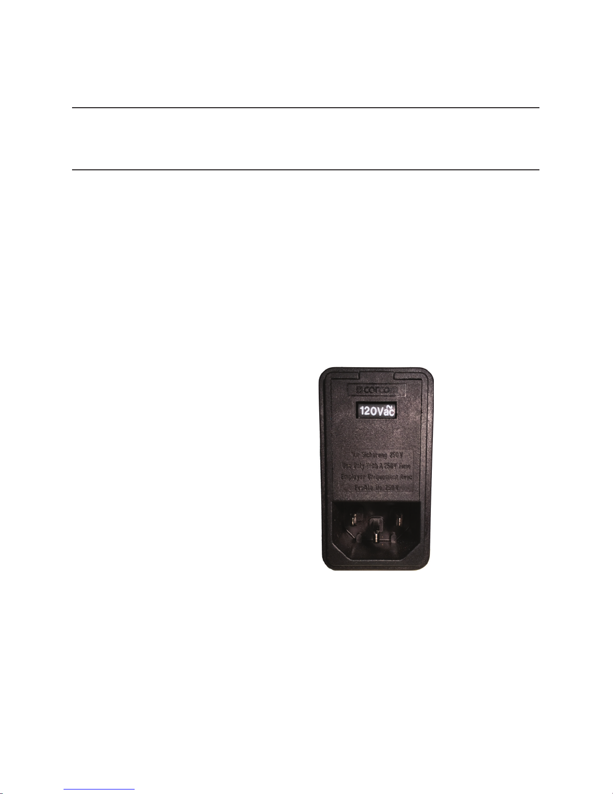
A.2 ac voltage selector
Figure A.1: The DC205 Power Entry module.
The DC205 line voltage selection is indicated by the white number
visible near the top of the power entry module. In the image above,
the line voltage selection is showing 120 V. Available settings are
100 V, 120 V, 220 V, and 240 V.
A–1
Page 54

A–2 Fuse and ac Line
The following steps describe how to change the line voltage selection:
1. Disconnect and remove the power cord.
2. Open the fuse cover using a small blade screwdriver or similar
tool, inserted at the point shown.
3. Insert the tool into the voltage selection slot and remove the
selector wheel from the housing.
4. Orient the selector wheel so that the desired line voltage will
show through the window.
5. Replace the wheel into the power entry module and close the
covor door, ensuring the selected voltage appears in the window.
6. If necessary, replace the fuse for the appropriate rating based
on line voltage.
DC205 Precision DC Voltage Source
Page 55

A.3 Fuse installation A–3
A.3 Fuse installation
The DC205 uses metric dual fuse installation. When installing or
replacing, be sure to replace both fuses.
The following steps describe how to install or replace the fuse:
1. Disconnect and remove the power cord.
2. Open the fuse cover using a small blade screwdriver or similar
tool.
3. Insert the tool into the right-hand side of each of the fuse holders, at the locations shown circled below. Gently extract the
two fuse holders.
DC205 Precision DC Voltage Source
4. Gently pry the old fuses out of the holders, and insert the new
fuses in their place. Be sure to use two (2) metric size 5 ×20 mm
fuses. The fuse should sit in the holder as shown:
5. Re-insert the fuse holders into the power entry module, being
sure to orient the white arrows as shown on the door. Push the
fuse holders all the way into the module.
6. Swing and push to snap the door back in place.
 Loading...