


Spencer® Vortex® |
|
|
Regenerative Blowers |
Serial No: |
|
|
|
|
|
|
|
|
|
|
|
Model No: |
|
|
|
|
|
|
|
Installation, Operation and |
|
|
Maintenance Instructions |
|
|
|
|
|
VB007
VB055
Important
Read and become familiar with this manual prior to uncrating and installing your Spencer Vortex Blower. Following the instructions detailed here will help you realize its full potential of efficient service and extended lifespan. Damage resulting from failure to follow correct procedure will void the warranty.
The Spencer Turbine Company Windsor, Connecticut 06095 |
Form ZZ15.1 |
Contents
I. General Page
Scope . . . . . . . . . . . . . . . . . . . . . . . . . . . . . . . . . 2
Limited Warranty . . . . . . . . . . . . . . . . . . . . . . . . . 2
Safety Precautions . . . . . . . . . . . . . . . . . . . . . . . 2
II. Installation
Locating, Mounting, Connecting . . . . . . . . . . . . . 2
Wiring . . . . . . . . . . . . . . . . . . . . . . . . . . . . . . . . . 3
III. Operation
Limits of Operation . . . . . . . . . . . . . . . . . . . . . 4-5
Temperature Rise . . . . . . . . . . . . . . . . . . . . . . . . 5
IV. Disassembly and Reassembly
General . . . . . . . . . . . . . . . . . . . . . . . . . . . . . . . . 5
Disassembly Procedure . . . . . . . . . . . . . . . . . . . 5
Reassembly Cautions . . . . . . . . . . . . . . . . . . . . . 5
Locknut Torque . . . . . . . . . . . . . . . . . . . . . . . . . . 6
V. Vortex Blower Data
Assembly Diagrams . . . . . . . . . . . . . . . . . . . . 6-17
Parts Lists . . . . . . . . . . . . . . . . . . . . . . . . . . . 6-17
Performance Curves . . . . . . . . . . . . . . . . . . . 6-17
VII. TroubleshootingGeneralGuide . . . . . . . . . . . . . . . . . . . . . 18
Scope
Information contained in this manual relates to Vortex Blowers standard and explosion-proof motor models VB001S, VB001, VB002S, VB002, VB003S, VB003, VB004S, VB004, VB007S, VB007, VB019S, VB019, VB030S, VB030, VB037S, VB037, VB055, VB075, and VB110.
Limited Warranty
We warrant that this product will be free from defects in material and workmanship for a period of 18 months from date of shipment or 12 months from date of startup, whichever comes first. Within the warranty period, we shall repair or replace F.O.B. our Factory such products that are determined by us to be defective.
This warranty will not apply to any product which has been subjected to misuse, negligence, or accident, or misapplied or improperly installed. This warranty will not apply to any product which has been disassembled, repaired, or otherwise altered by any persons not authorized by the Spencer Vortex Service Department.
On units which include thermal protection, the thermal protection must be connected as recommended.
The guarantee of the motor and control manufacturers will govern the extent of our guarantee on such equipment. Warranty work on motors and controls must be authorized by Spencer and must be performed in an authorized shop as designated by the manufacturers. The Spencer Turbine Company reserves the right to invoice all expenses incurred when repairs are made in the field at the specific request of the customer.
2
No assemblies or parts of assemblies will be accepted for repair or replacement under this warranty without prior authorization by The Spencer Turbine Company. For complete warranty information, obtain Spencerʼs Form 706, “Terms and Conditions of Sales.”
Safety Precautions
Power sources, protective devices, and grounding provisions must be in accordance with wiring instructions provided in this manual.
Blower becomes hot during operation and may cause burns if touched.
Do not operate the blower under load conditions which exceed the rated full-load amps on the nameplate.
Do not install the blower in any area which may have an explosive atmosphere or which may contain flammable gases or liquids. Always provide proper ventilation. Do not install in any area which may subject the blower to corrosive liquids. Excessive moisture may cause electrical failure; install the blower in areas free from water or rain. Do not operate blower without motor cooling fan cover, or without impeller end cover.
Before installing blowers with explosion-proof motors, the buyer must check federal, state and local codes to see if such motors are appropriate for the intended application environment. It is the buyerʼs responsibility to determine the suitability of any product for a particular purpose.
Storage
If machine is to be stored for an extended period of time, itIImust. Installationbe careful y pro ected from dampness and dirt. Locating, Mounting, Connecting
Ambient temperature at the installed location should not be less than -5˚ F or greater than 104˚ F. Relative humidity should not exceed 80%.
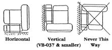
Mount the blower in a horizontal or vertical position as shown in Figure 1. For models VB055, VB075 and VB110, it is recommended to mount in the horizontal position only. Check with factory prior to mounting these models vertically.
Remove protective coverings, such as vinyl tape or plastic plugs, from the inlet and outlet ports. Models VB001, VB002 and VB003 are supplied with a patented (U.S. Patent 5,791,870) reversible flange with threaded pipe or tubing connections. Avoid excessive stress caused by pipe connector tightening or by misaligned pipe on the inlet and outlet ports. Support piping by brackets or other means.

In the event the blower is located where dust, fibers, drops of water, or other particulates may be in the airstream, use a filter on the suction side of the piping. If foreign matter enters the impeller, it may clog, jam, or otherwise impair the blower performance.
Wiring
Caution: Confirm that the power source is the same as that indicated on the unitʼs nameplate. Application of incorrect voltage or improper phase connection may cause motor failure or other damage.
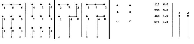
Use conductors and devices (such as the circuit breakers, starters, and switches shown in Figure 3) that are suitable for the applications shown in Tables 1 and 2 and are in compliance with the National Electric Code and applicable local codes and regulations. Motor terminal connections are shown below Table 1.
Provide protection from overheating of the motor windings. Some models are equipped with built-in thermal protectors (see Table 1). Where applicable, connect the leads from the pilot-duty thermal protector to the magnetic starter as shown in Fig. 3.
Check the direction of rotation of the blower. To reverse the direction or rotation:
1) for a single-phase motor, interchange motor leads 5 and 8.
2) for a three-phase motor, interchange any two of the three line connections.
Caution: Install a properly-sized overload device and disconnect in accordance with local codes and regulations and dedicated only to the Vortex Blower.
Furnish the Vortex Blower and all associated electrical devices with a proper ground in accordance with all local codes and regulations.
Fig. 3 Typical Wiring Diagram
The Spencer Turbine Company 600 Day Hill Road, Windsor, CT 06095 TEL 800-232-4321 860-688-8361 www.spencerturbine.com3
|
|
|
|
|
|
Table 1 Three-Phase Motor Data - Typical Values |
|
|
|
|
|
|
|
||||||||||||||||||||||||||
|
|
|
|
|
|
|
|
|
|
|
|
|
|
|
|
|
|
|
|
|
|
|
|
|
|
|
|
|
|
|
|
|
|
|
|
|
|
|
|
|
|
|
|
|
|
|
|
|
|
|
60 Hertz Operation |
|
|
|
|
|
|
|
|
|
|
|
|
|
|
|
|
|
|
|
|
|
|
|
|||||
|
Model No. |
|
VB001 |
|
|
|
|
VB002 |
|
|
|
VB003 |
|
|
|
|
|
VB004 |
|
|
|
|
|
|
|
|
VB007 |
|
|
VB019 |
|
|
|||||||
|
Power (hp) |
|
0.13 |
|
|
|
0.25 |
|
|
|
0.5 |
|
|
0.75 |
|
|
|
|
|
|
|
|
|
|
1.5 |
|
2.5 |
|
|
||||||||||
|
Voltage (V) |
|
200-230/460 |
|
|
200-230/460 |
|
|
|
208-230/460 |
|
|
200-230/460 |
|
|
|
200-230/460 |
|
200-230/460 |
|
|
||||||||||||||||||
|
FL Amp (A) |
|
.5-.48/.24 |
|
|
.86-.73/.37 |
|
|
|
1.8-1.6/.8 |
|
|
2.3-2.4/1.2 |
|
|
|
|
4.3-4/2 |
|
7.2-6.6/3.3 |
|
|
|||||||||||||||||
|
Voltage (V) |
|
|
|
|
|
|
575 |
|
|
|
575 |
|
|
575 |
|
|
|
|
|
|
|
|
|
|
575 |
|
575 |
|
|
|||||||||
|
FL Amp (A) |
|
|
|
|
|
|
.4 |
|
|
|
0.8 |
|
|
0.96 |
|
|
|
|
|
|
|
|
|
|
1.4 |
|
2.1 |
|
|
|||||||||
|
Model No. |
|
VB030 |
|
|
|
|
VB037 |
|
|
|
VB055 |
|
|
|
|
|
VB075 |
|
|
|
|
|
|
|
|
VB110 |
|
|
— |
|
||||||||
|
Power (hp) |
|
4 |
|
|
|
5 |
|
|
|
7.5 |
|
|
10 |
|
|
|
|
|
|
|
|
|
|
15 |
|
|
— |
|
||||||||||
|
Voltage (V) |
|
200-230/460 |
|
|
200-230/460 |
|
|
|
200-230/460 |
|
|
200-230/460 |
|
|
|
200-230/460 |
|
|
— |
|
||||||||||||||||||
|
FL Amp (A) |
|
10.6-10.2/5.1 |
|
|
13.2-12/6 |
|
|
|
19.8-17.2/8.6 |
|
|
27.5-27.2/13.6 |
|
|
39-37/18.5 |
|
|
— |
|
|||||||||||||||||||
|
Voltage (V) |
|
575 |
|
|
|
575 |
|
|
|
575 |
|
|
575 |
|
|
|
|
|
|
|
|
|
|
575 |
|
|
— |
|
||||||||||
|
FL Amp (A) |
|
3 |
|
|
|
4.8 |
|
|
|
7 |
|
|
9.6 |
|
|
|
|
|
|
|
|
|
|
13.5 |
|
|
— |
|
||||||||||
|
|
|
|
|
|
|
|
|
|
|
|
|
|
|
|
|
|
|
|
|
|
|
|
|
|
|
|
|
|
|
|
|
|
|
|||||
|
|
|
|
|
|
|
|
|
|
|
50 Hertz Operation |
|
|
|
|
|
|
|
|
|
|
|
|
|
|
|
|
|
|
|
|
|
|
|
|||||
|
|
|
|
|
|
|
|
|
|
|
|
|
|
|
|
|
|
|
|
|
|
|
|
|
|
|
|
|
|
|
|
|
|
|
|
|
|
|
|
|
Model No. |
|
VB001 |
|
|
|
|
VB002 |
|
|
|
VB003 |
|
|
|
|
|
|
VB004 |
|
|
|
|
|
|
|
|
|
VB007 |
|
|
VB019 |
|
||||||
|
Power (hp) |
|
0.13 |
|
|
|
0.21 |
|
|
|
0.5 |
|
|
0.63 |
|
|
|
|
|
|
|
|
|
|
1.25 |
|
2.1 |
|
|
||||||||||
|
Voltage (V) |
|
190-220/380-415 |
190-220/380-415 |
|
|
|
190/380-415 |
|
|
190/380-415 |
|
|
|
190/380-415 |
|
190/380-415 |
|
|
||||||||||||||||||||
|
FL Amp (A) |
|
.5-.52/.25-.26 |
|
|
.74-.66/.37-.34 |
|
|
|
2/1-.9 |
|
|
2.4/1.2-1.3 |
|
|
|
|
|
|
|
4/2 |
|
6.6/3.3-3.1 |
|
|
||||||||||||||
|
Model No. |
|
VB030 |
|
|
|
|
VB037 |
|
|
|
VB055 |
|
|
|
|
|
VB075 |
|
|
|
|
|
|
|
|
VB110 |
|
|
— |
|
||||||||
|
Power (hp) |
|
3.4 |
|
|
|
4.2 |
|
|
|
6.25 |
|
|
8.33 |
|
|
|
|
|
|
|
|
|
|
12.5 |
|
|
— |
|
||||||||||
|
Voltage (V) |
|
190/380-415 |
|
|
190/380-415 |
|
|
|
190/380-415 |
|
|
190/380-415 |
|
|
|
190/380-415 |
|
|
— |
|
||||||||||||||||||
|
FL Amp (A) |
|
10.2/5.2-5.1 |
|
|
11.8/5.9-5.6 |
|
|
|
17.6/8.8-8.2 |
|
|
27/13.5-14.5 |
|
|
|
36/18-17 |
|
|
— |
|
||||||||||||||||||
|
NOTE: Thermostats are provided on the VB004 and larger models. |
|
|
|
|
|
|
|
|
|
|
|
|
|
|
|
|
|
|
|
|
|
|
|
|
|
|
||||||||||||
|
|
|
|
|
|
|
|
|
|
|
|
|
|
|
|
|
|
|
|
|
|
|
|
|
|
|
|
|
|
|
|
|
|
|
|
|
|
|
|
|
|
|
|
|
|
|
|
MOTOR WIRING |
|
|
|
|
|
|
|
|
|
|
|
|
|
|
|
|
|
|
|
|
THERMOSTATS |
|
|
||||||||
|
|
|
|
|
|
|
|
|
|
|
|
|
|
|
|
|
|
|
|
|
|
|
|
|
|
|
|
|
|
||||||||||
|
|
Three-Phase |
|
|
|
|
Single-Phase |
|
|
Single-Phase |
|
|
|
|
|
VB004 AND LARGER |
|
|
|||||||||||||||||||||
|
Low Voltage |
|
High Voltage |
|
Low Voltage |
|
|
|
High Voltage |
|
|
Single Voltage |
|
|
|
|
|
Volts Amps |
|
Wiring |
|
|
|||||||||||||||||
|
|
|
|
|
|
|
|
|
50 Hertz Operation |
|
|
|
|
|
|
5 |
|
|
|
|
4 |
|
|
|
|
|
|
|
|
|
|
|
|
||||||
|
|
|
|
|
|
|
|
|
|
|
|
|
|
|
|
|
|
|
|
|
|
|
|
|
|
|
|
|
|
|
|
|
|
|
|||||
|
|
|
|
|
|
|
|
|
|
|
|
|
|
|
|
|
|
|
|
|
|
|
|
|
|
|
|
|
|
|
|
|
|||||||
|
|
|
|
|
|
|
|
|
|
|
|
|
|
|
|
|
|
|
|
1 |
|
|
|
8 |
|
|
|
|
|
|
|
|
|
|
|
|
|||
|
|
|
|
|
|
|
|
|
|
|
|
|
|
|
|
|
|
|
|
|
|
|
|
|
|
|
|
|
|
|
|
|
|
|
|
|
|
|
|
|
|
|
|
|
|
|
|
|
|
|
|
|
|
|
|
|
|
|
|
|
|
|
|
|
|
|
|
|
|
|
|
|
|
|
|
|
|
|
|
|
|
|
|
|
|
|
|
|
|
|
|
|
|
|
|
|
|
|
|
|
Line |
|
|
|
|
|
|
|
|
|
|
|
|
|
|
|
|
||
|
Line |
|
Line |
|
|
|
|
Line |
|
|
|
Line |
|
|
|
|
|
|
|
|
|
|
|
|
|
|
|
|
|
|
|
|
|
|
|
|
|
||
|
NOTES: (1) For three-phase, interchange any two line connections to reverse shaft rotation |
|
|
|
|
|
|
|
|
|
|
|
|
|
|
|
|
||||||||||||||||||||||
|
|
(2) For single-phase, interchange motor leads 5 and 8 to reverse shaft rotation |
|
|
|
|
|
|
|
|
|
|
|
|
|
|
|
|
|||||||||||||||||||||
|
|
|
|
|
|
|
|
|
|
|
|
|
|
|
|
|
|
|
|
|
|
|
|
|
|
|
|
|
|
|
|
|
|
|
|
|
|
|
|
|
|
|
|
|
|
|
|
|
|
|
|
|
|
|
|
|
|
|
|
|
|
|
|
|
|
|
|
|
|
|
|
|
|
|
|
|
|
|
|
|
|
|
|
|
|
Table 2 Single-Phase Motor Data - Typical Values |
|
|
|
|
|
|
|
||||||||||||||||||||||||||
|
|
|
|
|
|
|
|
|
|
|
|
|
|
|
|
|
|
|
|
|
|
|
|
|
|
|
|
|
|
|
|
|
|
|
|
|
|
|
|
|
|
|
|
|
|
|
|
|
|
|
60 Hertz Operation |
|
|
|
|
|
|
|
|
|
|
|
|
|
|
|
|
|
|
|
|
|
|
|
|||||
Model No. |
|
VB001S |
|
VB002S |
|
VB003S |
|
|
|
VB004S |
|
|
VB007S |
|
|
|
|
VB019S |
|
VB030S |
|
VB037S |
|
||||||||||||||||
Power (hp) |
|
0.13 |
|
0.25 |
|
|
0.5 |
|
|
|
0.75 |
|
|
1.5 |
|
|
|
|
|
|
|
|
2.5 |
|
|
|
4 |
|
|
5 |
|
|
|||||||
Voltage (V) |
|
115/230 |
|
115/230 |
|
115/230 |
|
|
|
115/208-230 |
115/208-230 |
|
115/208-230 |
|
115/208-230 |
|
230 |
|
|
||||||||||||||||||||
FL Amps (A) |
|
1.25/.63 |
|
2.3/1.15 |
|
5.2/2.6 |
|
|
|
9.6/5-4.8 |
|
|
13.4/6.7 |
|
22/11.5-11 |
|
34.8/18.5-17.4 |
|
20.8 |
|
|
||||||||||||||||||
|
|
|
|
|
|
|
|
|
|
|
50 Hertz Operation |
|
|
|
|
|
|
|
|
|
|
|
|
|
|
|
|
|
|
|
|
|
|
|
|||||
Model No. |
|
VB001S |
|
VB002S |
|
VB003S |
|
|
|
VB004S |
|
|
VB007S |
|
|
|
VB019S |
|
VB030S |
|
VB037S |
|
|||||||||||||||||
Power (hp) |
|
0.13 |
|
0.21 |
|
|
0.5 |
|
|
|
0.63 |
|
|
1.25 |
|
|
|
|
|
|
|
2.1 |
|
|
|
3.3 |
|
|
4.2 |
|
|
||||||||
Voltage (V) |
|
110/220 |
|
110/220 |
|
110/220 |
|
|
|
100-110/220 |
|
|
110/220 |
|
100-110/220 |
|
100-110/220 |
|
220 |
|
|
||||||||||||||||||
FL Amps (A) |
|
1.34/.67 |
|
2.1/1.05 |
|
5.6/2.8 |
|
|
|
9.9-11.6/5.8 |
|
|
15.4/7.7 |
|
22-21/10.5 |
|
42-38.6/19.3 |
|
19 |
|
|
||||||||||||||||||
4The Spencer Turbine Company 600 Day Hill Road, Windsor, CT 06095 TEL 800-232-4321 860-688-8361 www.spencerturbine.com
Year ofProduction
F
III. Operation
Limits of Operation
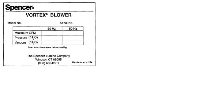
Operation at flows less than those indicated by the solid line on the applicable performance curve will cause overheating of the unit and is to be avoided. Throttling suction or discharge piping to reduce air volume increases differential pressure resulting in elevated temperature and increased power consumption. Use of pressure and/ or vacuum relief valve recommended. Maximum pressure and vacuum are indicated on the nameplate (see Fig. 4). These represent conditions at which the minimum allowable airflow (CFM) occurs. Check the operating pressure or vacuum to assure that the pressure or vacuum remains less than maximum. For continuous operation at low air volume (on the dotted portion of the performance curve), provide a bypass in the piping and operate at a lower pressure than maximum operating pressure. See Performance Curves, Section V.
Caution: Low flow conditions may produce heat levels which may cause burns. Do not touch the blower in operation.
Temperature Rise
A NEMA Class F insulation system is used in the motor. Maximum allowable winding temperature is 265˚F. If a thermal protector or thermal relay activates because the temperature rise of the motor is higher than usual, investigate and correct the problem. Explosion-proof motors use a NEMA Class B insulation. Typical causes of motor overheating are given in Section VI, Troubleshooting Guide.
IV. Disassembly and |
||
Reassembly |
|
|
A. General |
|
|
1. Precautions should be taken when disassembling |
||
or reassembling the blower. See Warranty Terms. |
||
2. Keep all parts clean. |
|
|
3. Do not overtighten bolts and screws. |
|
|
MOTOR |
|
|
“C” FACE |
IMPELLER |
|
|
HUB SHAFT |
THREADED |
|
|
PLATE |
|
|
BOLT |
|
SHIM BLOCK |
|
Fig. 5 Impeller Puller
B. Disassembly Procedure (Reassembly is performed in reverse order)
Caution: Shims are used to adjust the gap between the impeller and casing. When disassembling, take care to note the quantity of shims and their thickness. The shim stack replacement must be the correct thickness to assure proper clearance and to avoid degradation of performance.
1. Remove impeller cover; remove screws, pull cover away from case.
2. Unfasten lock washer; remove nut and washer.
3. Remove impeller from shaft by one of the following methods:
a. manually pull the impeller outward, OR
b. screw two bolts into tapped holes and pull on the bolts, OR (if the fit is tight)
c. use a puller assembly (not furnished) as shown in Fig. 5.
4. Remove motor shaft key.
5. Remove case from motor; if necessary remove screws holding case to base and motor to case.
6. Remove shims from motor shaft if necessary; do not discard them. See Note above.
Caution: Motors are heavy. Lift motor on models larger than VB002 by the eyebolt on the motor with an aid from a lifting device.
C. Reassembly Guidance
1. The gap between the impeller and case is essential for proper performance of the unit. The shims between the shaft collar and impeller hub establish the spacing of this gap. In reassembly, before installing the impeller cover, check the gap between the impeller and case to assure that the measurement conforms to the gap specification on the assembly drawing (on the following pages) for your unit.
The Spencer Turbine Company 600 Day Hill Road, Windsor, CT 06095 TEL 800-232-4321 860-688-8361 www.spencerturbine.com 5
2. For models VB001, VB002 and VB003, gap clearance between impeller and unibody case should be checked around entire periphery of the impeller in accordance with Item 18, impeller to case gap specification prior to securing impeller.
3 On models VB004 thru VB110 remove Item 23 Plug located on bottom of the case and check impeller gap with a feeler gauge. Remove impeller and adjust shims to meet gap specification. With adjustments and gap check complete, replace plug tightly to prevent air leakage.
4. Fasten impellers using lockwashers and locknuts. Torgue locknut to recommended torque values in Table 3. Bend a lockwasher tab down into a lockwasher slot.
5. Reattach the impeller cover.
|
|
|
Catalog No. |
Recommended |
|
Torque (Ft-Lb) |
||
|
||
VB001, VB001S, VB002 |
22 |
|
VB002S, VB003, VB003S |
||
|
||
VB004, VB004S |
31 |
|
|
|
|
VB007, VB007S |
36 |
|
|
|
|
VB019, VB019S |
36 |
|
|
|
|
VB030, VB030S |
44 |
|
|
|
|
VB037, VB037S |
44 |
|
|
|
|
VB055 |
77 |
|
|
|
|
VB075 |
90 |
|
|
|
|
VB110 |
90 |
|
|
|
|
Table 3 Locknut Torque |
||
V. Vortex Blower Data
Pages 7 through 17 present information about the various blower models. This information is important in understanding your blowerʼs performance, in using the blower in the proper operating range, and in ordering parts that might be needed.
A. Assembly Diagrams
At the top of each page is an assembly diagram of the unit. Items are identified by circled numbers around the diagram. Above each diagram is the gap specification.
B. Parts Lists
At the lower left of each diagram is a table giving the item number (shown on the Assembly Diagram), the Part No. for that item and the corresponding part description. In ordering parts, provide the model number, the part number and the description.
C. Performance Curves
At the lower right of each diagram are performance curves for 50Hz and 60Hz operation. The curves present the following information:
The upper line of each curve is pressure performance while the lower line is vacuum performance. The dashed portion at the left end of some of the curves indicates an intermittent-only operating area. See Operation Section on page 5.
D. Estimated Acoustical Noise Level at 1.5M, 60Hz
Model dba
VB001S 62
VB001 61
VB002S 61
VB002 61
VB003S 66
VB003 66
VB004S 63
VB004 63
VB007S 70
VB007 64
VB019S 70
VB019 73
VB030S 71
VB030 73
VB037S 74
VB037 76
VB055 82
VB075 81
VB110 80
6 The Spencer Turbine Company 600 Day Hill Road, Windsor, CT 06095 TEL 800-232-4321 860-688-8361 www.spencerturbine.com
 Loading...