


Spencer® Power Mizer®
Multistage Centrifugal
Cast Blowers
Operating and
Maintenance Manual
Serial No.
Model No.
Important
Read and become familiar with this manual prior to installing your Spencer blower. Following the instructions detailed here will help you realize its full potential of efficient service and extended lifespan. Damage resulting from failure to follow correct procedure will void the warranty.
Form WW6.4

Contents |
Page |
||
I |
Introduction................................................................... |
2 |
|
|
Product Description........................................................ |
3 |
|
II |
Limited Warranty.......................................................... |
3 |
|
III Safety Precautions and Operating Guidelines........... |
4 |
||
IV |
Handling and Storage................................................... |
4 |
|
|
Lifting and Moving........................................................... |
4 |
|
|
Storage........................................................................... |
5 |
|
|
Unpacking....................................................................... |
5 |
|
V |
Installation..................................................................... |
5 |
|
|
Location.......................................................................... |
5 |
|
|
Foundation...................................................................... |
5 |
|
|
Blower Setup.................................................................. |
5 |
|
|
1. |
Piping.................................................................... |
5 |
|
2. Flexible Connectors............................................... |
5 |
|
|
3. |
Butterfly Valve....................................................... |
6 |
|
4. |
Filters, Silencers and Filter Silencers.................... |
6 |
|
5. Check Valve.......................................................... |
6 |
|
|
6. |
Electrical................................................................ |
6 |
|
7. Coupling Alignment............................................... |
6 |
|
|
8. Bearing Lubrication............................................... |
7 |
|
|
9. Shaft Seals............................................................ |
7 |
|
|
10. Motor Rotation....................................................... |
7 |
|
VI |
Operation and Adjustments......................................... |
7 |
|
|
Startup Precautions........................................................ |
7 |
|
|
Blower Startup................................................................ |
8 |
|
|
Surge.............................................................................. |
8 |
|
|
Normal Operating Limits................................................. |
8 |
|
|
Periodic Operation.......................................................... |
8 |
|
|
Parallel Installation.......................................................... |
8 |
|
VII |
Lubrication.................................................................... |
8 |
|
|
Motor Bearings............................................................... |
8 |
|
|
Blower Bearings–Grease Lubricated.............................. |
8 |
|
|
Blower Bearings–Oil Lubricated..................................... |
9 |
|
|
Flexible Couplings........................................................ |
10 |
|
VIII |
Maintenance................................................................ |
10 |
|
|
Blower Bearing Removal and Replacement................. |
10 |
|
|
Bearing Illustrations...................................................... |
10 |
|
|
Labyrinth Seal Removal and Replacement.................. |
10 |
|
|
Field-Replaceable Parts............................................... |
13 |
|
|
Equipment Service........................................................ |
13 |
|
|
Material Safety Data Sheets......................................... |
13 |
|
|
Emergency Service....................................................... |
13 |
|
|
Service and Operating Assistance................................ |
13 |
|
IX |
Troubleshooting Guide.............................................. |
13 |
|
|
Insufficient Air or Gas................................................... |
13 |
|
|
Machine Noisy.............................................................. |
14 |
|
|
Motor Hot...................................................................... |
14 |
|
|
Vibrating Machine......................................................... |
15 |
|
|
Oil Leaks....................................................................... |
15 |
|
I. Introduction
Welcome as a Spencer customer and owner of a new Power Mizer centrifugal blower. Your blower incorporates the latest engineering and casting technology, based on more than a century of Spencer leadership in blower design and manufacture.
This manual contains the information you need for handling, installing, operating and maintaining your new equipment correctly, to ensure trouble-free operation and long service life. Please read it thoroughly.
If you have any questions about the procedures or recommendations presented, call your Spencer Representative for advice. The Spencer Service and Engineering Departments are also available to provide assistance.
Be sure the machine model number and serial number are correctly recorded in the boxes on the front cover of this manual. These numbers may be found on the nameplate (see sample below) located on the blower discharge head.
Having this information easily accessible will expedite parts orders and other communication with the factory. To serve your maintenance and repair needs promptly, Spencer maintains a large inventory of parts for all blower models. Fieldreplaceable parts are listed on page 13.
PowerMizer
Read instructions before handling and starting equipment
Serial No.
Model No.
Manufactured under the following Registered Trademarks: 62,801; 140,976; 652,701; 1,854,029; 134,026; 341,418; 1,348,270; 959,254; 595,312; 7,218,204; 7,218,205; 7,218,284
Use Original Factory Parts & Service
The Spencer Turbine Company, Windsor, CT 06095
800-232-4321 860-688-8361 www.spencerturbine.com
Made in U.S.A. |
Plate No. PLN90055 |
2

Product Description
Spencer Power Mizer blowers are multistage centrifugal units which handle air and other gases, working either as blowers or exhausters. They increase the pressure of the incoming air or gas by guiding it from one stage to the next through diffusers. They are centrifugal because the flow through the blower is turned perpendicular to the axis of rotation.
The blower casing has three main sections constructed of cast iron: inlet, return channels and discharge. The inlet and discharge are flanged and drilled to ANSI 125#/150# standards. External steel tie rods hold the return channels between the inlet and discharge sections. There are no external moving parts except the shaft that connects to the power source–typi- cally an electric motor, but other drivers such as a steam turbine or internal combustion engine are available.
The internal rotor assembly consists of a steel shaft supporting cast aluminum alloy impellers with varying combinations of radial and backward curved blades. The impellers are individually dynamically balanced, then keyed to the shaft and the impeller/spacer stack is secured with a locknut. Finally, the complete rotor assembly is checked to be sure the total amplitude of vibration is no more than 0.23 in/sec at the bearing housing.
The rotor assembly is supported at both ends by antifriction bearings designed for an L-10 bearing life of 100,000 hours. Depending on intended blower use, either labyrinth seals or carbon ring seals are provided. See page 7 for Shaft Seal discussion.
Series 7000 and 8000 blowers are also equipped with an internal balance piston. As the largest Power Mizer models, these blowers develop high differential pressures with correspondingly high thrust loads. The balance piston is designed to lessen the thrust load, protecting the bearings from overloading.
II. Limited Warranty
We warrant that this product will be free from defects in material and workmanship for a period of 18 months from date of shipment or 12 months from date of startup, whichever comes first. Within the warranty period, we shall repair or replace, F.O.B. our Factory, such products that are determined by us to be defective.
This warranty will not apply to any product which has been subjected to misuse, negligence or accident, or misapplied or improperly installed. This warranty will not apply to any product which has been disassembled, repaired or otherwise altered by any persons not authorized by the Spencer Service Department.
The guarantees of the motor, control and component manufacturers govern the extent of our guarantee on such equipment. Warranty work on motors, controls and components must be authorized by Spencer and must be performed in an authorized shop as designated by the motor, control and component manufacturers. The Spencer Turbine Company reserves the right to invoice all expenses incurred when repairs are made in the field at the specific request of a customer.
3
III. Safety Precautions and
Operating Guidelines
•Read and follow all instructions in this manual. If you have any questions, consult your Spencer Representative.
•Use appropriately rated lifting equipment for installation, removal, or disassembly of heavy components.
•Remove inlet and discharge covers, silica gel bags and crating materials prior to blower installation.
•Inspect all openings for tools and foreign matter before connecting accessories or piping.
•Perform all installing and operating procedures with care, following sound practices to avoid accidents and damage.
•Avoid climbing on or over the blower; use proper staging and ladders for exterior machine access.
•Be sure isolation pads are correctly located beneath the blower base. See page 5.
•Confirm that the blower is level so that oil level readings will be accurate.
•Install flexible connectors on inlet and discharge flanges to isolate piping loads from the blower.
•Ensure that piping, machine guards and accessories such as filters or valves are properly installed and fastened.
•Fill oilers of oil-lubricated blower bearings with recommended type of fresh oil as instructed on page 7.
•Install a filter on the inlet when the blower is used in pressure service and keep it clean.
•Allow only qualified electricians to work on electrical equipment.
•Lock electrical circuits open and tag them during servicing of equipment.
•Align the coupling as instructed on page 6.
•Remove alignment tools and replace coupling guard before restarting blower.
•Turn the blower shaft by hand to verify free rotation without rubbing or noise.
•Check motor rotation as instructed on page 7.
•Do not operate the blower where there is an ambient temperature above 104°F (40°C), unless it has been designed for such conditions.
•Operate blower with sufficient restriction at all times (via connected piping system or throttled butterfly valve) to avoid motor overloading.
•Do not allow blower operation in surge (unstable low flow) or damage may result.
•Rotate shaft of stored or inactive blowers a few times by hand every week.
•Use only genuine Spencer parts for repairs and service.
IV. Handling and Storage
Each Spencer blower is carefully balanced and tested at the factory. For optimum performance, it must be handled with care during unloading and installation.
Check the shipment for damage upon arrival; file any claims with the shipper and notify Spencer.
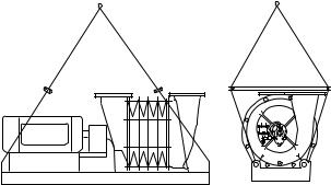
Lifting and Moving
Moving of this equipment is the customer’s responsibility and should be performed or directed by experienced riggers using accepted rigging practices and safety precautions. The blower/ motor assembly can be lifted and relocated with an overhead crane or hoist. Always use lifting equipment rated for the loads involved–see accompanying table of approximate machine weights.
Caution: Use of alternative lifting methods such as a forklift is not recommended, due to risk of equipment damage or misalignment.
Approximate Machine Weights
(blower and base without motor)
|
Weight |
|
|
|
Weight |
||
Model No. |
lb |
kg |
Model No. |
lb |
kg |
||
C13 |
177 |
80 |
C44 |
3487 |
1584 |
||
C14 |
188 |
85 |
C45 |
4115 |
1868 |
||
C15 |
200 |
91 |
C46 |
4544 |
2063 |
||
CS22 |
1047 |
475 |
C47 |
4997 |
2269 |
||
CS23 |
1224 |
555 |
C48 |
5425 |
2463 |
||
CS24 |
1404 |
637 |
C52 |
3852 |
1747 |
||
CS25 |
1625 |
737 |
C53 |
4518 |
2049 |
||
CS26 |
1805 |
819 |
C54 |
5344 |
2424 |
||
CS27 |
1986 |
901 |
C55 |
6010 |
2726 |
||
CS28 |
2217 |
1006 |
C56 |
6676 |
3028 |
||
CS29 |
2395 |
1086 |
C57 |
7542 |
3421 |
||
CS210 |
2576 |
1169 |
C58 |
8208 |
3723 |
||
C32 |
1917 |
870 |
C62 |
4914 |
2231 |
||
C33 |
2225 |
1009 |
C63 |
6064 |
2753 |
||
C34 |
2596 |
1178 |
C64 |
6989 |
3173 |
||
C35 |
2928 |
1328 |
C65 |
8049 |
3654 |
||
C36 |
3285 |
1490 |
C66 |
8926 |
4052 |
||
C37 |
3688 |
1673 |
C72 |
10150 |
4604 |
||
C38 |
4004 |
1816 |
C73 |
12100 |
5489 |
||
CS32 |
1980 |
898 |
C74 |
14600 |
6623 |
||
CS33 |
2319 |
1052 |
C75 |
17200 |
7804 |
||
CS34 |
2823 |
1281 |
C76 |
20300 |
9207 |
||
CS35 |
3162 |
1434 |
C81 |
14500 |
6577 |
||
CS36 |
3501 |
1588 |
C82 |
18000 |
8165 |
||
CS37 |
4019 |
1823 |
C83 |
21500 |
9752 |
||
CS38 |
4358 |
1977 |
C84 |
25000 |
11340 |
||
CS39 |
4697 |
2131 |
C85 |
28500 |
12927 |
||
C42 |
2630 |
1194 |
C86 |
32000 |
14515 |
||
C43 |
3058 |
1389 |
|
|
|
|
|
|
|
|
|
|
|
|
|
|
|
|
|
|
|
|
|
4

Use lifting eyes supplied on the blower base, along with a suitable quad leg chain sling or spreader bars with the smallest practical angle between the sling legs to minimize stress.
CAUTION: Do not use slings around the blower; they will bend or stress the tie rods. Never lift the blower by its shaft. Do not disturb the oilers or any electrical devices.
Storage
If a blower is stored for an extended period before use or between uses, protect it from dampness, dirt and vibration. Suspend bags of silica gel desiccant in the inlet and discharge. Cover the entire blower if possible or at least cover the inlet and discharge openings to keep out foreign matter. Rotate the blower shaft a few times by hand every week, keeping a log.
CAUTION: Failure to comply with the required storage provisions, including weekly shaft rotations, will void the warranty.
Unpacking
1.Uncrate the blower, saving all literature, boxes and parts.
2.Remove inlet and discharge protective caps and all packing materials.
3.Use the packing slip to check off and confirm the presence of all ordered components.
4.Read any instructional and warning labels on the machine before installation and operation.
V. Installation
NOTE: If any problems are encountered during installation or startup, consult your local Spencer Representative.
Location
CAUTION: Do not locate blower or controls where they will be subject to ambient temperatures above 104 °F (40 °C) during operation, unless specially equipped for higher temperatures.
Power Mizer blowers may be installed outdoors, preferably under cover, or indoors. When choosing an indoor location, be sure there is sufficient ventilation to allow unrestricted airflow to the blower. In addition, it is advisable to leave several feet of space around the blower and motor for ease of servicing. Inaccessibility can prove costly.
Consideration should be given to the noise generated by this equipment and its contribution to the ambient noise level. Optional noise reduction accessories include blower casing sound attenuation jackets, filter silencers or silencers for the blower inlet and/or discharge, and silencers for the motor.
NOTE: Duct noise attenuation is a customer responsibility.
Foundation
CAUTION: Oil-lubricated machines must be level or oil level readings will be inaccurate.
A level concrete pad is recommended, although any flat level surface that can support the machine weight is satisfactory. The blower base should be placed level on the furnished isolation pads or equivalent. The number and location of pads are important. Pads must be located directly under a support for maximum performance. Locate one pad under each supporting member of the blower.
Locate the motor pads under the vertical motor base supports, not necessarily directly under the motor feet. Four pads per side will avoid any springboard effect. Each pad must be shimmed, if necessary, to ensure that it is carrying its share of the load. If lag bolts and nuts are used to restrain the blower, hand-tighten only.
NOTE: Spencer does not favor grouting; however grouting may be used consistent with established practice. Do not use isolation pads when grouting.
Discharge
Inlet
Butterfly |
|
Check |
Valve |
|
|
|
Valve |
|
|
Flexible |
|
|
|
|
|
Connectors |
|
(Shim if necessary.)
Recommended Pad Locations
Blower Setup
CAUTION: Make sure blower inlet and discharge ports are unobstructed before connecting piping to blower.
1. Piping
All piping connected to the blower should be of ample size to minimize frictional loss. All system joints must be airtight; leaky pipes waste air and power.
All piping must be properly aligned and supported to avoid stress on the blower and restrained to prevent movement away from the blower caused by air pressure. Flexible connectors must be used to connect piping to the blower.
NOTE: The diagram above shows the proper orientation of a piping elbow in-line with the blower shaft. The butterfly valve should have its shaft at right angles to the blower shaft and the valve should open as indicated (counterclockwise in this example). These steps will assure uniform loading of the blower’s first stage.
2. Flexible Connectors
CAUTION: Connected piping must not touch the blower. Use flexible connectors (expansion joints or rubber sleeves) on both the inlet and discharge to create an isolating gap between blower and piping.
5
 Loading...