


Spencer® SOH, 4BOH |
|
|
Serial No: |
|
|
& 4BOB Multistage |
|
|
Model No: |
|
|
Centrifugal Blowers |
|
|
|
|
|
|
|
|
Operating and |
|
|
Maintenance Manual |
|
|
|
|
|
4BOB Four-Bearing Outboard
SOH Standard Overhung
4BOH Four-Bearing Overhung
Important
Read and become familiar with this manual prior to installing your Spencer blower. Following the instructions detailed |
|
here will help you realize its full potential of efficient service and extended lifespan. Damage resulting from failure to follow |
|
correct procedure will void the warranty. |
|
The Spencer Turbine Company Windsor, Connecticut 06095 |
Form AA15.4 |

Contents |
|
Page |
|
I |
Introduction . . . . . . . . . . . . . . . . . . . . . . . . . . . |
. . |
. . . .2 |
|
Product Description . . . . . . . . . . . . . . . . . . . . |
. . |
. . . .3 |
II |
Limited Warranty . . . . . . . . . . . . . . . . . . . . . . . . |
. . |
. . .3 |
III |
Safety Precautions & Operating Guidelines . . |
. . |
. . .3 |
IV |
Handling and Storage . . . . . . . . . . . . . . . . . . . . |
. . |
. . .4 |
|
Lifting and Moving . . . . . . . . . . . . . . . . . . . . . . |
. . |
. . .4 |
|
Storage . . . . . . . . . . . . . . . . . . . . . . . . . . . . . . . |
. . |
. . .4 |
|
Unpacking . . . . . . . . . . . . . . . . . . . . . . . . . . . . |
. . |
. . .4 |
V |
Installation . . . . . . . . . . . . . . . . . . . . . . . . . . . . . |
. . |
. . .4 |
|
Location . . . . . . . . . . . . . . . . . . . . . . . . . . . . . . |
. . |
. . .4 |
|
Foundation . . . . . . . . . . . . . . . . . . . . . . . . . . . . |
. . |
. . .4 |
|
Blower Setup . . . . . . . . . . . . . . . . . . . . . . . . . . |
. . |
. . .4 |
|
1. Piping . . . . . . . . . . . . . . . . . . . . . . . . . . . . . |
. . |
. . .4 |
|
2. Flexible Connectors . . . . . . . . . . . . . . . . . . |
. . |
. . .4 |
|
3. Butterfly Valve . . . . . . . . . . . . . . . . . . . . . . . |
. . |
. . .5 |
|
4. Filters, Silencers and Filter Silencers . . . . . |
. . |
. . .5 |
|
5. Check Valve . . . . . . . . . . . . . . . . . . . . . . . . |
. . |
. . .5 |
|
6. Electrical . . . . . . . . . . . . . . . . . . . . . . . . . . . |
. . |
. . .5 |
|
7. Coupling Alignment . . . . . . . . . . . . . . . . . . . |
. . |
. . .5 |
|
8. Shaft Seals . . . . . . . . . . . . . . . . . . . . . . . . . |
. . |
. . .7 |
|
9. Motor Rotation . . . . . . . . . . . . . . . . . . . . . . |
. . |
. . .7 |
VI |
Operation and Adjustments . . . . . . . . . . . . . . . |
. . |
. . .7 |
|
Startup Precautions . . . . . . . . . . . . . . . . . . . . . |
. . |
. . .7 |
|
Blower Startup . . . . . . . . . . . . . . . . . . . . . . . . . |
. . |
. . .7 |
|
Surge . . . . . . . . . . . . . . . . . . . . . . . . . . . . . . . . |
. . |
. . .8 |
|
Normal Operating Limits . . . . . . . . . . . . . . . . . |
. . |
. . .8 |
|
Periodic Operation . . . . . . . . . . . . . . . . . . . . . . |
. . |
. . .8 |
|
Parallel Installation . . . . . . . . . . . . . . . . . . . . . . |
. . |
. . .8 |
VII |
Lubrication . . . . . . . . . . . . . . . . . . . . . . . . . . . . . |
. . |
. . .8 |
|
Motor Bearings . . . . . . . . . . . . . . . . . . . . . . . . . |
. . |
. . .8 |
|
Blower Bearings, 4BOH & 4BOB . . . . . . . . . . . |
. . |
. . .8 |
|
Flexible Couplings, 4BOH & 4BOB . . . . . . . . . |
. . |
. . .9 |
VIII |
Maintenance . . . . . . . . . . . . . . . . . . . . . . . . . . . . |
. . |
. . .9 |
|
Replacement Parts . . . . . . . . . . . . . . . . . . . . . . |
. . |
. . .9 |
|
Equipment Service . . . . . . . . . . . . . . . . . . . . . . |
. . |
. . .9 |
|
Material Safety Data Sheets . . . . . . . . . . . . . . |
. . |
. . .9 |
|
Emergency Service . . . . . . . . . . . . . . . . . . . . . |
. . |
. . .9 |
|
Service and Operating Assistance . . . . . . . . . . |
. . |
. . .9 |
|
SOH Diagram and Recommended Spare Parts |
. . .10 |
|
|
SOH Disassembly/Reassembly Instructions . . |
. . |
. .11 |
|
4BOH Diagram and Recommended Spare Parts |
. .12 |
|
|
4BOH Disassembly/Reassembly Instructions |
. . . . .13 |
|
|
4BOB Diagram and Recommended Spare Parts . |
. .14 |
|
|
4BOB Disassembly/Reassembly Instructions |
. . . . .15 |
|
IX |
Troubleshooting Guide . . . . . . . . . . . . . . . . . . . |
. . |
. .16 |
|
Insufficient Air or Gas . . . . . . . . . . . . . . . . . . . . |
. . |
. .16 |
|
Machine Noisy . . . . . . . . . . . . . . . . . . . . . . . . . |
. . |
. .17 |
|
Machine Vibrating . . . . . . . . . . . . . . . . . . . . . . . |
. . |
. .17 |
|
Motor Hot . . . . . . . . . . . . . . . . . . . . . . . . . . . . . |
. . |
. .18 |
I. Introduction
Welcome as a Spencer customer and owner of a new centrifugal blower. Your blower incorporates exclusive Spencer engineering technology, based on more than a century of leadership in blower design and manufacture.
This manual contains the information you need for handling, installing, operating and maintaining your new equipment correctly, to ensure trouble-free operation and long service life. Please read it thoroughly. Illustrations and instructions contained here apply to three series of blowers; Standard Overhung (SOH), Four Bearing Overhung (4BOH) and Four Bearing Outboard (4BOB). If you need assistance in determining which model you have, please consult your Spencer Representative.
Your Spencer Representative will also answer any questions you may have about the procedures or recommendations presented in this manual. The Spencer Service and Engineering Departments can provide assistance as well.
Be sure the machine model number and serial number are correctly recorded in the boxes on the front cover of this manual. These numbers may be found on the nameplate (see samples below) located on the machine housing.
Having this information easily accessible will expedite parts orders and other communication with the factory. To serve your maintenance and repair needs promptly, Spencer maintains a large inventory of parts for all blower models.
2
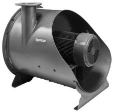
Product Description Standard Overhung Design These Spencer blowers are multistage centrifugal units which handle air and other gases, working either as blowers or exhausters. They increase the pressure of the incoming air or gas by guiding it from one stage to the next through diffusers. They are centrifugal because the flow through the blower is turned perpendicular to the axis of rotation.
The most prevalent Spencer blower configuration is the standard overhung type which has all the impellers mounted directly on an extended motor shaft.
The four-bearing overhung blower uses a standard shaft motor and an overhung impeller design. The rotating blower assembly is supported by a rigid ball bearing bracket and shaft, which is connected to the motor via a flexible coupling.
In four-bearing outboard blowers, the impellers are mounted on a shaft supported betw en two outbo rd be rings and driven by aIIstandard. Limitedshaft mo or throughWarrantya flexible coupli g.
We warrant that this product will be free from defects in material and workmanship for a period of 18 months from date of shipment or 12 months from date of startup, whichever comes first. Within the warranty period, we shall repair or replace, F.O.B. our Factory, such products that are determined by us to be defective.
This warranty will not apply to any product which has been subjected to misuse, negligence or accident, or misapplied or improperly installed. This warranty will not apply to any product which has been disassembled, repaired or otherwise altered by any persons not authorized by the Spencer Service Department. The guarantees of the motor, control and component manufacturers govern the extent of our guarantee on such equipment. Warranty work on motors, controls and components must be authorized by Spencer and must be performed in an authorized shop as designated by the motor, control and component manufacturers. The Spencer Turbine Company reserves the right to invoice all expenses incurred when repairs are made in the field at the specific request of a customer. For complete warranty information, refer to Form 706, “Spencer's Terms and Conditions of Sales.”
Ill. Safety Precautions
and Operating
Guidelines
• Read and follow all instructions in this manual. If you have any questions, consult your Spencer Representative.
• Use appropriately rated lifting equipment for installation, removal or disassembly of heavy components.
• Remove inlet and discharge covers, silica gel bags and crating materials prior to blower installation.
• Inspect all openings for tools and foreign matter before connecting accessories or piping.
• Perform all installing and operating procedures with care, following sound practices to avoid accidents and damage.
• Avoid climbing on or over the blower; use proper staging and ladders for exterior machine access.
• Be sure isolation pads are placed beneath the blower. See page 4.
• Install flexible connectors on inlet and discharge flanges to isolate piping loads from the blower.
• Ensure that piping, machine guards and accessories such as filters or valves are properly installed and fastened.
• Install a filter on the inlet when the blower is used in pressure service and keep it clean.
• Allow only qualified electricians to work on electrical equipment.
• Lock electrical circuits open and tag them during servicing of equipment.
• Align the coupling as instructed on page 5 (4BOH and 4BOB blowers only). Then remove alignment tools and replace coupling guard before restarting blower.
• Turn the blower shaft by hand to verify free rotation without rubbing or noise.
• Check motor rotation as instructed on page 7.
• Do not operate the blower where there is an ambient temperature above 104°F (40°C), unless it has been designed for such conditions.
• Operate blower with sufficient restriction at all times (via connected piping system or throttled butterfly valve) to avoid motor overloading.
• Do not allow blower operation in surge (unstable low flow) or damage may result.
• Rotate shaft of stored or inactive blowers a few times by hand every week.
• Use only genuine Spencer parts for repairs and service.
3

IV. Handling and
Storage
Each Spencer blower is carefully balanced and tested at the factory. For optimum performance, it must be handled with care during unloading and installation.
Check the shipment for damage upon arrival; file any claims with the shipper and notify Spencer.
Lifting and Moving
Moving of this equipment is the customerʼs responsibility and should be performed or directed by experienced riggers using accepted rigging practices and safety precautions. The blower/ motor assembly can be lifted and relocated with a forklift, overhead crane or hoist. Always use lifting equipment rated for the loads involved.
CAUTION: Do not lift the blower by its shaft or bearing housing; use the furnished lifting eyes or slots in the blower base.
Storage
If a blower is stored for an extended period before use or between uses, protect it from dampness, dirt and vibration. Suspend bags of silica gel desiccant in the inlet and discharge. Cover the entire blower if possible or at least cover the inlet and discharge openings to keep out foreign matter. Rotate the blower shaft a few times by hand every week, keeping a log.
CAUTION: Failure to comply with the required storage provisions, including weekly shaft rotations, will void the warranty.
Unpacking
1. Uncrate the blower, saving all literature, boxes and parts.
2. Remove inlet and discharge protective caps and all packing materials.
3. Use the packing slip to check off and confirm the presence of all ordered components.
4. Read a y in tructional nd warni g labels on the machine Vbefore. Installationi stallation nd operat on.
NOTE: If any problems are encountered during installation or startup, consult your local Spencer Representative.
Location
CAUTION: Do not locate blower or controls where they will be subject to ambient temperatures above 104°F (40°C) during operation, unless specially equipped for higher temperatures.
Spencer blowers may be installed outdoors, preferably under cover, or indoors. When choosing an indoor location, be sure there is sufficient ventilation to allow unrestricted airflow to the blower. In addition, it is advisable to leave several feet of space around the blower and motor for ease of servicing. Inaccessibility can prove costly.
4
Consideration should be given to the noise generated by this equipment and its contribution to the ambient noise level. Optional noise reduction accessories include blower housing sound attenuation jackets, filter silencers or silencers for the blower inlet and/or discharge, and silencers for the motor.
NOTE: Duct noise attenuation is a customer responsibility.
Foundation
A level concrete pad is recommended, although any flat level surface that can support the machine weight is satisfactory. The blower base should be placed level on the furnished isolation pads or equivalent. Each pad must be shimmed, if necessary, to ensure that it is carrying its share of the load. If lag bolts and nuts are used to restrain the blower, hand-tighten only.
NOTE: Spencer does not recommend grouting of machines.
|
|
Inlet |
Discharge |
|
|
Check |
|
Butterfly |
Valve |
Flexible |
Valve |
|
|
|
|
Connectors |
|
Blower Setup
CAUTION: Make sure blower inlet and discharge ports are unobstructed before connecting piping to blower.
1. Piping
All piping connected to the blower should be of ample size to minimize frictional loss. All system joints must be airtight; leaky pipes waste air and power.
All piping must be properly aligned and supported to avoid stress on the blower and restrained to prevent movement away from the blower caused by air pressure. Flexible connectors must be used to connect piping to the blower.
NOTE: The diagram above shows the proper orientation of a piping elbow in-line with the blower shaft. The butterfly valve should have its shaft at right angles to the blower shaft and the valve should open as indicated (counterclockwise in this example). These steps will assure uniform loading of the blowerʼs first stage.
2. Flexible Connectors
CAUTION: Connected piping must not touch the blower. Use flexible connectors (expansion joints or rubber sleeves) on both the inlet and discharge to create an isolating gap between blower and piping.
3. Butterfly Valve
To regulate (throttle) blower volume and/or pressure, a butterfly valve may be installed—preferably on the inlet. A valve may also be installed on the discharge as an isolation valve.
4. Filters, Silencers and Filter Silencers
Spencer blowers will accept a filter or filter silencer, typically on the inlet, and a silencer, typically on the discharge. Inlet filtration is recommended for pressure applications.
5. Check Valve
CAUTION: A check valve must be installed in the discharge line (downstream of any blow-off line) of each blower operating in parallel, or in the inlet line (upstream of any bleed line) of each vacuum producer operating in parallel to prevent reverse flow through idle units.
Orient the check valve during installation to equalize loading on the valve shutters. Usually, the hinge post of the check valve should be installed perpendicular to the blower shaft. If the check valve is installed in a horizontal piping line, position the valve shaft vertically. Make sure the internal moving parts can move freely.
6. Electrical
NOTE: All wiring and electrical adjustments or installations must be done by a qualified electrician in accordance with the National Electrical Code and local codes.
CAUTION: The electrical service at the installation site must supply the voltage stamped on the motor nameplate. Operation at an incorrect voltage may damage the motor and void its warranty.
In making electrical connections, follow the wiring instructions furnished. Wire and fuses should be of ample capacity to ensure that proper voltage is maintained at the motor terminals while starting and running. It is important that proper starting equipment is used. The starters should have thermal overload protection as well as true low-voltage protection.
Electrical Accessories. The following optional safety accessories are available from Spencer. For copies of the product bulletins listed, contact your Spencer Representative or www.spencerturbine.com.
• Load Control Safety Switch (LCSS)—Bult. No. TDS-223
• Electronic Modulating Bleed Control (EMBC)— Bult. No.
TDS-224
• Bearing Temperature Monitor Control (BTMC)— Bult. No.
TDS-222
• Standard Blower Safety Control Panels (LCSS, BTMC and VM, Vibration Monitor)—Bult. No. TDS-237 and TDS-236
NOTE: Use of a BTMC, vibration monitor and an LCSS or EMBC may be advisable in crucial or unattended applications, anywhere there are wide load fluctuations or where machines are operating at high pressure or vacuum.
Both the LCSS and EMBC are designed to prevent a blower or |
||
vacuum producer from operating in a low load (surge) condition. |
||
7. Coupling Alignment, 4BOH & 4BOB |
||
The coupling on this machine was carefully aligned at the factory |
||
and the coupling halves and shell(s) marked to indicate opti- |
||
mum relative position. However, transportation may have |
||
caused coupling misalignment. |
|
|
CAUTION: Check the motor and blower shafts for misalign- |
||
ment and carefully realign them if necessary after installa- |
||
ti on an d b ef or e s tart up , as m is al ig nm en t c an caus e |
||
destru cti ve v ibratio n. Co upl ing alig nmen t sh ould be |
||
rechecked again after an hourʼs operation. Final alignment |
||
should be made at average operating temperature. After |
||
each alignment check, add lubricant per instructions and |
||
replace coupling guard. |
|
|
WARNING: DISCONNECT AND LOCK OUT ELECTRICAL |
||
POWER BEFORE PERFORMING ALIGNMENT. |
||
On certain |
blowers, the coupling is disassembled after factory |
|
alignment and marking. The coupling halves are specially pro- |
||
tected against the elements during shipping. Prior to startup, |
||
assemble the coupling, align keyways using factory markings |
||
and lubricate as instructed. |
|
|
Coupling alignment lines up the motor shaft and blower shaft in |
||
horizontal and vertical planes. It also ensures an adequate |
||
clearance (gap) between the two coupling halves. Only quali- |
||
fied personnel should attempt to align a coupling. If problems |
||
arise, contact Spencer or your Spencer Representative. |
||
Sier Bath Gear-Type Couplings, manufactured to our rigid |
||
specifications, are most commonly supplied with Spencer |
||
equipment. |
|
|
|
Sier Bath |
Hub to Hub |
Coupling Size, in. |
Gap, in. |
|
|
7/8 |
1/8 |
|
1-1/2 |
1/8 |
|
2 |
1/8 |
|
2-1/2 |
1/4 |
|
3 |
1/4 |
|
3-1/2 |
1/4 |
|
4 |
1/4 |
|
4-1/2 |
1/4 |
|
5 |
1/4 |
Remove one snap ring and slide the sleeve off the hub halves. Using a feeler gage, verify that the gap between the coupling halves agrees with this table.
CAUTION: Some motor shafts are spring-loaded axially. Be careful when using the feeler gage to avoid compressing the shaft and disturbing the normal at-rest position.
Machinery Soft Foot
Imperfections or unevenness between the machine base and any foot of the motor or blower creates a condition known as soft foot, which may be parallel or angular. If uncorrected, soft foot leads to increased stress and high vibration. Although both the motor and blower feet were preset at the factory, each foot must be checked for soft foot prior to alignment. Any vertical or angular soft foot that exceeds .003” is excessive and must be corrected.
5
Laser Alignment Technique (Recommended)
Laser systems have significant advantages such as reduced maintenance costs and energy consumption; prolonged life for bearings, seals and couplings; decreased bearing temperatures and lower vibration levels. Many laser systems also identify and measure soft foot conditions.
NOTE: Consult an alignment specialist if laser equipment is not available.
Blower Shaft |
Motor Shaft |
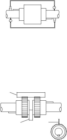
Reverse Indicator Method (Permissible)
This method may be done electronically following the instrument manufacturerʼs instructions or by means of dial indicators as follows:
1. Reinstall the coupling sleeve, seal and snap ring.
2. Clamp dial indicators on shafts 180° apart as shown. 3. Place indicator probes on opposite shafts as shown.
4. Rotate both shafts simultaneously in the correct operating direction, taking readings at 90° intervals.
5. Adjust motor to achieve parallel and angular alignment. If questions arise, contact the Spencer Service Department.
Straightedge
Blower Shaft |
Motor Shaft |
Feeler Gage |
Straightedge |
Motor
Shaft
Straightedge Method (Permissible)
1. Remove old lubricant and clean the hub teeth.
2. Set a machine shop quality straightedge across the coupling hubs (at the root diameter of the gear teeth).
3. Adjust the motor so the straightedge is evenly supported between the coupling hubs at the 3, 6, 9 and 12 oʼclock positions.
4. Using a feeler gage, measure the clearance between the coupling hubs at the 3, 6, 9 and 12 oʼclock positions.
5. Adjust the motor so the gap is identical at all four positions and in accord with the table of hub to hub gaps.
Coupling Alignment with Sleeve Bearing Motors
CAUTION: Complete the following procedures before attempting coupling alignment with sleeve bearing motors.
Use a flange-type gear coupling for both 1800 and 3600 RPM motors. Do not use a sleeve-type coupling.
Sleeve bearing motors have a specified end play. End play limits and the magnetic center (where motor will run) should be scribed on the shaft by the manufacturer.
Use the following procedure to align a sleeve bearing motor with a blower.
1. Make sure the motor shaft is level.
2. Position the motor so that when the rotor is pushed toward the blower as far as it will go, there will 0.030" clearance between the ends of the motor and blower shafts (or the alignment faces on the coupling hubs).
3. Proceed with coupling alignment using the appropriate instructions.
Alignment Tips
• Make sure the blower is level before alignment.
• Mark the axial location of the motor before alignment as a reference point to be sure it does not move.
• Avoid disturbing any factory-installed shims unless they are to be replaced.
• Do soft foot corrections first; loosen all mounting bolts before correcting any foot.
• During the final vertical adjustment of the motor, work on one side at a time, loosening the jack bolts first so the motor does not move laterally as mounting bolts are loosened.
• Use the smallest shim that will slide over the mounting bolts.
• Minimize the number of shims. One thick shim and 2-3 thin shims are usually satisfactory.
• Remove all traces of dirt or contaminants from shims and machine parts.
• Use stainless steel shims only.
• Never reuse shims.
CAUTION: After each alignment check, add coupling lubricant if required.
WARNING: REPLACE THE COUPLING GUARD BEFORE RESTARTING THE BLOWER.
6
 Loading...