


Spencer®
Vacuum
Cleaning Systems
Serial No:
Model No:
Filter Bags:
Handling, Installing and
Operating Instructions
Important
Do not operate machine in unstable, low-flow range (surge).
Read and become familiar with this manual prior to uncrating and installing your Spencer Vacuum equipment. This precision equipment is capable of extended service and lifespan. Realization of this potential can best be achieved through proper handling and adherence to the instructions detailed here. Damage resulting from failure to follow correct procedures will void warranty.
The Spencer Turbine Company Windsor, Connecticut 06095 USA www.spencerturbine.com |
Form EE9.1 |
Contents |
Page |
|
I |
General Instructions ........................................................ |
2 |
II |
Coupling Alignment ......................................................... |
4 |
III |
How to Order Replacement Parts ................................... |
5 |
IV |
Lubrication Instructions ................................................... |
6 |
V |
Standard Overhung ......................................................... |
8 |
VI |
Four Bearing Overhung ................................................ |
10 |
VII |
Four Bearing Outboard ................................................. |
12 |
VIII |
Centrifugal Separator .................................................... |
14 |
IX |
Tubular Bag Separator................................................... |
14 |
X |
Filter Bag Information..................................................... |
15 |
XI |
Wet Separator ................................................................ |
16 |
XII |
Portable Wet Separator.................................................. |
16 |
XIII |
Trouble Shooting Guide - Separators ............................ |
17 |
XIV |
Trouble Shooting Guide ............................................ |
18-19 |
I. General Instructions
Illustrations contained here apply to three types of Spencer Fabricated Vacuum Producers. Use the illustrations or consult factory to determine which machine you have, then read instructions paying particular attention to those which are unique to your machine. When in doubt, consult Spencer. For Power Mizer® Cast Centrifugal Vacuum Producers refer to Form WW for handling, installing and operating instructions.
Important
Read and become familiar with this manual prior to uncrating and installing or storing machinery—it is a precision piece of equipment capable of extended service and lifespan. Realization of this potential can best be achieved through proper handling and adherence to the following instructions. Damage resulting from failure to follow correct procedures will void warranty.
Spencer Service
Spencer service begins upon receipt of your request for equipment purchase. Our engineers welcome the opportunity to discuss your problems and will assist in determining specification requirements if so desired. To serve you promptly, we maintain a large inventory of electric motors and machine parts. Also, by combining under one roof the constantly supervised manufacturing, assembly, and test procedures, Spencer can assure you of a unit capable of optimum performance under the most severe service conditions. All Spencer machines are factory tested for load capacities and vibrational characteristics. This assures long, trouble-free operations.
Warranty
We warrant that this product will be free from defects in material and workmanship for a period of 18 months from date of shipment or 12 months from date of startup, whichever comes first. Within the warranty period, we shall repair or replace, F.O.B. our Factory or designated service center, such products that are determined by us to be defective.
This warranty will not apply to any product which has been subjected to misuse, negligence, or accident or, misapplied or improperly installed. This warranty will not apply to any product which has been disassembled, repaired or otherwise altered by any persons not authorized by our Service Department.
The guarantee of the motor, control, and component manufacturers govern the extent of our guarantee on such equipment.
Warranty work on motors, controls, and components must be authorized by Spencer and must be performed in an authorized shop as designated by the motor, control, and component manufacturers. The Spencer Turbine Company reserves the right to invoice all expenses incurred when repairs are made in the field at the specific request of the customer.
Handling
Caution: Do not lift by the shaft end or bearing housing; use lift rings or slots in base.
This machine has been carefully balanced and tested at our factory. It is essential that it be handled with care during installation in order that you may be assured satisfactory performance.
Storage
Caution: If machine is to be stored for an extended period of time, it must be carefully protected from dampness and dirt and the shaft should be rotated a few times by hand, every week.
On Four Bearing Overhung and/or Four Bearing Outboard type machines, bearings must be replaced at customer expense if start up occurs one year beyond date of shipment.
Failure to comply with any of the preceding will void warranty.
Location
Caution: Do not locate unit or controls in excessively hot area (> 104˚F) unless the equipment has been specifically designed for this condition.
Before placing the machine in its operating position, be sure that the vacuum system components are readily accessible for servicing by allowing several feet of clear space around the machine. Inaccessibility can prove costly in both time and labor.
Foundation
Caution: Vacuum Producers should not be bolted down.
No special foundation is necessary for Spencer Vacuum Producers. A level concrete floor or block is recommended, although any other substantial non-resonant floor will prove satisfactory. The Vacuum Producer’s base should be placed on the furnished cork isolating pads or equivalent. Level machine by inserting shims between cork pads and machine frame, if necessary.
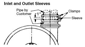
Tubing
Tubing should be properly aligned and supported so as not to produce any stress or strain on the machine casing. It is necessary that a flexible connector be used to connect the machine to the tubing system. It is necessary that tubing be restrained to prevent its movement away from the Vacuum Producer due to air pressure when it is operated.
2 Note: For complete warranty information, including our limitation of liability, consult Spencer’s Terms and Conditions of Sale - Form 706.

All tubing should be of ample size to minimize frictional loss. It is absolutely essential that all joints be airtight and that there be no leaks in the system. Leaky air pipes consume a surprising amount of power and impair the operating efficiency of the system.
A rubber connecting sleeve is supplied with most machines. It should be installed so that it covers a gap of approximately one inch as illustrated. The mounting clamps should be tightened to effect an airtight connection.
It is important that the tubing or piping not touch or butt the Vacuum Producer; there must be a gap between the machine and piping or tubing.
Electrical
Caution: Be sure motor, starter, controls and other electrical equipment is the proper type suitable for the application and environment and complies with all applicable codes.
Be sure that the motor furnished with this machine is rated for the same type of voltage available at the installation site. In making the electrical connections, follow the wiring instructions furnished. Wire and fuses should be of ample capacity to insure that proper voltage is maintained at the motor terminals while starting and running. It is important that proper starting equipment be used. All AC machines should be equipped with a magnetic contactor or a manual or automatic compensator depending on the machine size and the installation regulations of the local power company. The starters should have thermal overload protection as well as true low-voltage protection.
Start-Up
Coupling-Equipped Machines
Caution: Before start-up, the coupling must be aligned in accordance with the information contained in Section II, Coupling Alignment, or with the manufacturer’s instructions accompanying each coupling.
The following procedures apply to start-up of all Spencer Vacuum Producers.
Caution: The Vacuum Producer must be electrically wired with regard to the correct direction of rotation. A direction- of-rotation arrow is affixed to the casing. To check rotation direction depress start button, immediately depress stop button and observe that the motor drive shaft rotation coincides with the arrow attached to the casing. Available discharge positions (viewed from intake end) and the correct relationship of the discharge position to rotation are shown in the following diagram.
Under no circumstances should the Vacuum Producer be operated without being connected to the tube system with which it is used or motor overload will occur.
When starting up a Vacuum Producer it is recommended that a blast gate or other control device be closed. When first starting the Vacuum Producer, an ammeter should be connected to the motor circuit and the control device opened
until full load current is reached. At this point, the blast gate locking nut should be tightened. This prevents motor overload. The blast gate may then be used for throttling purposes. Current readings at motor must be compared with readings on ammeters (when furnished) to be sure they are the same. If readings are not the same, contact Spencer’s Service Department.
Periodic Operation
Caution: All Vacuum Producers should be operated periodically. This can be accomplished through bi-weekly alternate operation of the machine(s).
Parallel Operation
Caution: Check valves must be installed on the inlet of each Vacuum Producer connected in parallel to prevent air flow back through the unit not in operation. When operating two or more Vacuum Producers in parallel it is necessary to be sure that each machine carries its respective share of the load.
After accomplishing start-up of each machine, proceed as follows. Check the current reading at each motor to be sure they are the same. If current readings are approximately the same it indicates Vacuum Producers are sharing equal system load. It may be necessary to re-adjust the control device to attain similar readings on the ammeters.
In most cases low flow protection for the equipment is required.
Caution: Operation of Positive Displacement Vacuum Producers in parallel with Centrifugal Vacuum Producers is not recommended and may result in damage to the Centrifugal Vacuum Producer.
Surge (Unstable Low Flow)
Caution: Do not operate the Vacuum Producer below the minimum safe operating flow. Operation below the minimum flow will result in surge or in excessive discharge temperatures. Damage to the Vacuum Producer because of operating below minimum safe flow will not be covered by Spencer warranty.
A unit in surge can produce a breathing or pulsating discharge noise. It may also be detected by movement on an ammeter scale or manometer. Increasing the volume flow sufficiently should eliminate this condition. This may be accomplished by bleeding air into the Vacuum Producer.
3
II. Coupling Alignment
For Power Mizer® Cast Centrifugal Vacuum Producers refer to Form WW.
Caution: The coupling on this machine was carefully aligned at the factory and the coupling halves and shell(s) marked to indicate optimum relative position. However, transportation may have caused coupling misalignment. It is essential, therefore, that the motor and Vacuum Producer shafts be checked for misalignment and carefully realigned if necessary after installation and before start-up, as misalignment can cause destructive vibration.
Coupling alignment should be rechecked again after an hour’s operation. Final alignment should be made at average operating temperature. After each alignment check, add lubricant per instructions and replace coupling guard.
On certain Vacuum Producers, the coupling is disassembled after factory alignment and marking. The coupling halves are specially protected against the elements and the machine is shipped. Prior to start-up, it is necessary on these machines to assemble, align key ways using factory markings, and lubricate in accordance with the instructions supplied with the machine and contained here.
Coupling alignment provides for aligning, in the horizontal and vertical planes, the motor shaft with the blower shaft, and insuring adequate clearance (gap) between the two coupling halves. Only qualified maintenance personnel should attempt to align a coupling. If doubt exists as to competency or if problems arise contact The Spencer Turbine Company.
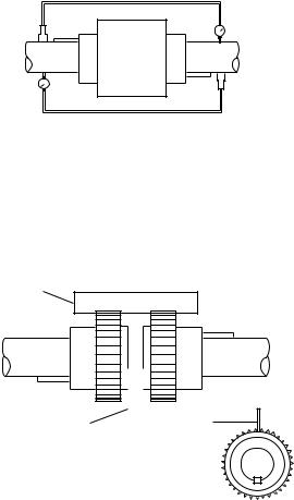
Sier Bath Coupling (See accompanying illustrations)
Sier Bath gear type couplings are the most common coupling supplied with Spencer equipment. These are manufactured to our rigid specifications.
Sier Bath |
Dimension “C” (hub to hub) |
|
Coupling Size |
Gap |
|
7/8 |
1/8 |
|
1 1/2 |
1/8 |
|
2 |
1/8 |
|
2 1/2 |
1/4 |
|
3 |
1/4 |
|
3 1/2 |
1/4 |
|
4 |
1/4 |
|
4 1/2 |
1/4 |
|
5 |
1/4 |
|
6 |
1/4 |
|
7 |
3/8 |
|
9 |
1/2 |
|
11 |
1/2 |
|
12 |
1/2 |
|
Remove one snap ring and slide the sleeve off the hub halves. Using a feeler gauge, verify that the gap between coupling halves, is in accordance with the chart above.
Caution: Be careful because some motor shafts are spring loaded axially. When using a feeler gauge take care not to compress the shaft and disturb the normal at-rest position.
To align this coupling, Spencer recommends one of the following procedures.
Blower Shaft |
Motor Shaft |
Reverse Indicator Method (Preferred)
1.Reinstall the coupling sleeve, seal and snap ring.
2.Clamp dial indicators on shafts, 180 degrees apart.
3.Place indicator probes on opposite shafts as shown.
4.Rotate both shafts simultaneously in the correct operating direction, taking readings at 90 degree intervals.
5.Adjust motor to achieve parallel and angular alignments. If questions arise, contact the Spencer Service Dept.
Straightedge
Blower Shaft |
Motor Shaft |
|
|
Straightedge |
Feeler Gauge |
|
Motor
Shaft
Straight Edge Method (Permissible)
1.Remove the old lubricant and clean the hub teeth.
2.Set a machine shop quality straight edge across the coupling hubs (at the root diameter of the gear teeth).
3.Adjust the motor so the straight edge is evenly supported between the coupling hubs at the 3, 6, 9, and 12 o’clock positions.
4.Using a feeler gauge, measure the clearance between the coupling hubs at the 3, 6, 9, and 12 o’clock positions.
5.Adjust the motor so that the gap is identical at the 3, 6, 9, and 12 o'clock positions and in accordance with the dimension “C”.
Caution: Be sure to relubricate coupling after alignment and before operation.
Coupling Alignment with Sleeve Bearing Motors
Caution: Where sleeve bearing motors are used, it is necessary to complete the following procedures before coupling alignment is attempted.
Unless otherwise specified by the customer, a flange type gear coupling should be used for both 1800 and 3600 RPM applications. Do not use a sleeve type coupling.
Sleeve bearing motors have a specified end play. End play limits and the magnetic center (where motor will run) should be scribed on the shaft by the manufacturer.
4

When aligning a sleeve bearing motor with a machine, use the following procedure:
1.The motor shaft must be level.
2.Position the motor so that when the rotor is pushed toward the machine as far as it will go, there will be 0.030 clearance
between the ends of the machine and motor shafts (or the alignment faces on the coupling hubs).
3.Proceed with the coupling alignment in accordance with applicable instructions.
III. Replacement Parts
How to order replacement parts
When ordering replacement parts, it is important that the information you furnish to Spencer is correct and complete. Be sure when reading nameplates that you obtain the correct information. Record nameplate information on one of the typical nameplates shown here and on the cover to use as a reference when ordering parts. Remember, the more complete the information, the quicker the order will be processed; incomplete information will result in unnecessary delays and expense through callbacks. When in doubt, consult the factory for further information.
To order replacement parts, furnish the following:
1.Record machine serial number and catalog/model number from machine nameplate.
2.Record motor horsepower from motor nameplate.
3.Measure and record the casing diameter.
4.Refer to applicable illustration in the instruction manual and locate needed item by its circled call-out number. Refer to call-out list for nomenclature and record.
5.When ordering impellers and deflectors be sure to include the letter designation shown on the applicable illustration. An alternate method would be to count the number of impellers from the end of the casing.
6.Include the form number from which you have extracted the nomenclature. The form number is shown in the bottom right corner of the cover page and will read AA, EE, etc.
Typical Nameplate
The following are recommended spare parts:
Tubular bag separator.
Complete set of replacement bags.
Standard Overhung (refer to drawing on page 9 for item numbers).
Item Number |
Nomenclature |
2 |
Division head packing |
4 |
Rope packing |
9 |
Interstage packing |
12 |
End head gasket |
15 |
Drive End motor bearing |
19 |
Opposite Drive End motor bearing |
Four Bearing Overhung (refer to drawing on page 11 for item numbers).
Item Number |
Nomenclature |
1 |
Flexible coupling |
5 |
Coupling End bearing |
5A |
Blower End bearing |
6 |
Division head packing |
14 |
Interstage deflector packing |
16 |
End head gasket |
18 |
Rope packing |
21 |
Drive End motor bearing |
23 |
Opposite Drive End motor bearing |
Four Bearing Outboard (refer to drawing on page 13 for item numbers).
Item Number |
Nomenclature |
2 |
Drive End motor bearing |
3 |
Flexible coupling |
10 |
Rope packing |
18A |
Outboard bearing(s) |
20 |
End head packing |
22 |
End head gasket |
25 |
Interstage deflector packing |
32 |
Division head packing |
34 |
Inboard bearing |
37 |
Opposite Drive End motor bearing |
38 or 39 |
Metallic packing (if machine equipped with |
|
packing box). |
5

IV. Lubrication
Instructions
For Power Mizer® Cast Centrifugal Vacuum Producers refer to Form WW.
Caution: Recommended bearing grease is Chevron SRI, Number 2. Use of any other grease will void warranty.
General
Proper lubrication procedure is important to Vacuum Producer maintenance. These instructions should be closely followed to assure trouble-free operation of the equipment.
Standard Overhung Lubrication
Spencer’s Standard Overhung Vacuum Producers do not require lubrication except for motor bearing lubrication required by the motor manufacturer. See paragraph entitled Motor
Bearing Lubrication.
Four Bearing Overhung and Four Bearing Outboard Bearing Lubrication
Spencer Four Bearing Overhung and Outboard Vacuum Producers are equipped with deep-groove radial ball bearings designed to carry the thrust and radial loads. These bearings are packed with the proper amount and grade of lubricant before the unit is shipped from the factory. For this reason, lubrication prior to first operation is not recommended and should not be attempted.
Bearing Lubrication Procedure and Frequency Guide
Lubrication is required based on operating frequency and conditions. Many bearing failures are caused by excess grease which results in over-heating and consequent bearing failure.
The Vacuum Producer bearings, as lubricated at the factory, carry an adequate amount of proper grade of grease for 1500 to 8000 hours of continuous operation prior to lubrication, depending upon atmospheric conditions and size. An average lubrication interval therefore should be established based on existing conditions. Several factors contribute to frequency of lubrication:
1.Operating temperatures (bearing)
2.Indoor or outdoor operation
3.Dusty or clean atmosphere
4.Ambient temperature
5.Predicted duty cycle
6.Bearing size and speed
6
Assuming an ideal 8000 hour lubrication interval, reduce the time factor by applying the preceding conditions as follows:
|
|
|
*Lubrication Interval |
Operating Condition |
Blower Bearings |
||
|
|
|
|
I. |
1. 120˚F to 170˚F bearing |
4000-6000 average |
|
|
|
temperature |
operating hours |
|
2. |
Indoor installation |
|
|
3. |
Clean atmosphere |
|
|
4. |
40˚F to 100˚F ambient |
|
|
|
temperature |
|
|
5. |
Continuous operation |
|
II. |
Same conditions as “I”, |
6000-8000 average |
|
|
above except: |
operating hours |
|
|
|
Intermittent operation |
|
III. |
1. 120˚F to 170˚F bearing |
3000-5000 average |
|
|
|
temperature |
operating hours |
|
2. |
Outdoor installation |
|
|
3. All atmosphere |
|
|
|
|
conditions |
|
|
4. |
0˚F to +120˚F ambient |
|
|
|
temperature |
|
|
5. |
Continuous operation |
|
IV. |
Same conditions as “III”, |
5000-7000 average |
|
|
above except: |
operating hours |
|
|
|
Intermittent operation |
|
|
|
|
|
*Note: Higher limits apply to smaller bearings (#308 and smaller). Lower limits apply to large bearings.
An extremely dirty atmosphere, in addition to the above factors, could decrease the lubrication period as much as 50%.The above chart serves only as a guide.
To lubricate blower bearings, proceed as follows:
1.Shut down machine.
2.Remove guards as necessary.
3.Inject the recommended grease (Chevron SRI No. 2) using a grease gun. The amount of grease will vary with bearing size.
4.Reinstall guards and restart the machine.
Caution: Do not run Vacuum Producer unless guards are properly installed.
Recommended Bearing Lubricant Type
The bearings of Four Bearing Outboard and Four Bearing Overhung Turbo Vacuum Producers are packed at the factory with Chevron SRI, Number 2 grease. The general specifications are:
Grade or consistency . . . . . . . . . . . . . . . . . . . . . . . . . . . . . . .#2 Thickener . . . . . . . . . . . . . . . . . . . . . . . . . . . . . . . . . . .polyurea ASTM Dropping Point . . . . . . . . . . . . . . . . . . . . . . . . . . . .480˚F Work Penetration . . . . . . . . . . . . . . . . . . . . . . . . . . . . . . . . .270 Base Oil Viscosity . . . . . . . . . . . . . . . . . . . . .600 SUS @ 100˚F Color . . . . . . . . . . . . . . . . . . . . . . . . . . . . . . . . . . . .Blue-Green
Chevron SRI, Number 2 is available from Spencer.
Note: The intermixing of incompatible greases will result in loss of lubrication and bearing failure which is NOT covered under the Spencer warranty.
 Loading...