

Page 1

Survey Pro Field Software
User Guide
From V5.2
Page 2

IMPORTANT, READ THIS AGREEMENT CAREFULLY. BY INSTALLING OR USING ALL OR ANY PORTION OF THE SOFTWARE, YOU ARE ACCEPTING ALL OF
THE TERMS AND CONDITIONS OF THIS AGREEMENT. YOU AGREE THAT
THIS AGREEMENT IS ENFORCEABLE LIKE ANY WRITTEN AGREEMENT.
IF YOU DO NOT AGREE TO ALL OF THESE TERMS AND CONDITIONS, DO NOT
USE OR ACCESS THE SOFTWARE. IF YOU HAVE PAID A LICENSE FEE FOR
USE OF THE SOF TWARE AND DO NOT AGREE TO THESE TE RMS, YOU MAY
RETURN THE SOFTWARE (ALONG WITH ANY HARDWARE ON WHICH IT WAS
EMBEDDED, IF APPLICABLE) FOR A FULL REFUND PROVIDED YOU (A) DO
NOT USE THE SOFT WARE AND (B) RETURN THE SOFTWARE WITHIN THIRTY
(30) DAYS OF YOUR INITIAL PURCHASE.
IF YOU WISH TO USE THE SOFTWARE AS AN EMPLOYEE, CONTRACTOR, OR
AGENT OF A CORPORATION, PARTNERSHIP OR SIMILAR ENTITY, THEN YOU
MUST BE AUTHORIZED TO SIGN FOR AND BIND THE ENTITY IN ORDER TO
ACCEPT THE TERMS OF THIS AGREEMENT. THE LICENSES GRANTED UNDER THIS AGREEMENT ARE EXPRESSLY CONDITIONED UPON ACCEPTANCE
BY SUCH AUTHORIZED PERSONNEL.
IF YOU HAVE ENTERED INTO A SEPARATE WRITTEN LICENSE AGREEMENT
WITH LICENS OR FOR USE OF THE SOFTWARE, THE TE RMS AND CONDITIONS OF SUCH OT HER AGREEMENT SH ALL PREVAIL OVER ANY CONFLICTING TERMS OR CONDITI ONS IN THIS AGREEMENT.
This End User License Agreement (“Agreement”) is between Trimble Navigation
Limited, located at 935 Stewart Drive, Sunnyvale, CA 94085 and/or its affiliates
(“Licensor”) and the customer (individual or entity) that has downloaded or otherwise procured the licensed Software (as defined below) for use as an end user
(“you”). This Agreement covers any Software and supporting technical documentation provided with the Software (“Documentation”).
1.Definitions
“Effective Date” means the earlier of the date you sign an Order Form or the date
on which the Software is first made available to you.
“Order Form” means any order which is entered into by Licensor (or an authorized distributor or reseller of Licensor) and you under which you are provided
the Software. Each Order Form for the Software shall be deemed a part of this
Agreement. This Agreement is binding on you whether or not you executed an
Order Form with Licensor. Order Forms may not vary the terms of this Agreement. Only a written agreement, signed by Licensor (not a Licensor distributor
or reseller) may vary the terms of this Agreement.
“Software” means the Licensor software product(s) provided in connection with
this Agreement in object code form (or as otherwise specified in any related Order Form). “Software” shall also include any releases provided to or purchased
by you under any separate support and maintenance agreement you may enter
into with Licensor. Unless otherwise noted, the Software and Documentation are
referred to collectively herein as “Software.”
“Third-Party Software” means any third-party software that is provided to you by
Licensor under this Agreement or under separate terms and conditions.
“Licensor Supplier” means either Licensor or an authorized distributor or reseller of Licensor products or services which has entered into an Order Form with
you.
2.License
2.1.Grant of License. Subject to all of the terms and conditions of this Agreement, Licensor grants you a non-transferable, non-sublicensable, non-exclusive
license to use the Software in machine-readable form on any computer and operating system for which it was intended, but solely (a) for your own internal
business purposes at the location specified in the applicable Order Form (the
“Site”); (b) in accordance with the Documentation; and (c) in accordance with
any additional license term, subscription term or other user, seat, computer,
field of use or other restrictions set forth in the applicable Order Form or otherwise specified upon purchase.
2.2.Installation and Copies. Licensor shall make available the Software and
Documentation by disk, other media, or as embedded in a device, or make it
available for download in electronic form. Licensor shall also provide you with
electronic passwords or other enabling mechanisms if necessary to permit the
licensed usage of the Software. All licenses shall commence, and delivery shall
be deemed to occur, as of the Effective Date (or, if later, such date on which the
Software and license keys are first made available to you). If your Order Form is
with a Licensor distributor or reseller, that distributor or reseller (and not Licensor) is solely responsible for delivery to you and Licensor has no liability for any
failure to deliver. If the Software requires license keys to operate as licensed to
you, Licensor or the applicable Licensor Supplier will deliver such license keys
to you.
SOFTWARE END USER LICENSE AGREEMENT
2.3.Software Intended to be Installed on Computers. You may copy and install
on your computers for use only by your employees the number of copies of the
Software for which you have paid the applicable license fee. You may transfer
the Software from one computer to another computer provided that the computer to which the Software is transferred is located at the Site and the Software is
completely removed and de-installed from the prior computer. If you are permitted to install the Software on a network server, and you transfer the Software
from the site to a new location, you must provide Licensor with written notice of
the new site prior to such transfer. You may also make a reasonable number of
copies of the Software for back-up and archival purposes. This Section 2.3 does
not apply to any software embedded on devices.
2.4.License Restrictions. You shall not (and shall not allow any third party to):
(a) decompile, disassemble, or otherwise reverse engineer the Software or attempt to reconstruct or discover any source code, underlying ideas, algorithms,
file formats or programming interfaces of the Software by any means whatsoever
(except and only to the extent that applicable law prohibits or restricts reverse
engineering restrictions); (b) distribute, sell, sublicense, rent, lease, or use the
Software (or any portion thereof) for time sharing, hosting, service provider, or
like purposes; (c) remove any product identification, proprietary, copyright, or
other notices contained in the Software; (d) modify any part of the Software, create a derivative work of any part of the Software, or incorporate the Software into
or with other software, except to the extent expressly authorized in writing by Licensor; (e) attempt to circumvent or disable the security key mechanism that
protects the Software against unauthorized use (except and only to the extent
that applicable law prohibits or restricts such restrictions); or (f) publicly disseminate performance information or analysis (including, without limitation,
benchmarks) from any source relating to the Software. If the Software has been
provided to you as embedded in any hardware device, you are not licensed to
separate the Software from the hardware device. If the Software has been: (i)
provided to you separately from a hardware device but is intended to be loaded
onto a hardware device specified by Licensor (such as a firmware update or other
Software programs that are designed for use on a specific hardware device such
as surveying software), or (ii) provided to you pre- loaded onto a specific hardware device, your license is limited to use of the Software on the device specified by Licensor, and for no other use.
2.5.Evaluation Software. Subject to the terms and conditions of this Agreement
and during the term of this Agreement, Licensor may, in its discretion, provide
you with pre-release, beta or other software on an evaluation basis (“Evaluation
Software”). You may use Evaluation Software solely for internal evaluation purposes for 30 days from receipt of the Evaluation Software (unless otherwise
agreed by Licensor in writing) (the “Evaluation Period”). Unless you pay the applicable license fee for the Software, the Evaluation Software may become inoperable and, in any event, your right to use the Evaluation Software automatically
expires at the end of the Evaluation Period. Evaluation Software shall be subject
to all restrictions on Software set forth in this Agreement. You shall treat all Evaluation Software as Confidential Information of Licensor and shall return or destroy any copies of Evaluation Software upon expiration of the applicable
Evaluation Period. Any and all suggestions, reports, ideas for improvement and
other feedback of any type you provide regarding the Evaluation Software are the
sole property of Licensor, and Licensor may use such information in connection
with any of its products or services without any obligation or restriction based on
intellectual property rights or otherwise. You acknowledge that all Evaluation
Software is provided “AS IS” and may not be functional on any machine or in
any environment. THE WARRANTIES OF SECTION 6 DO NOT APPLY TO EVALUATION SOFTWARE. LICENSOR AND ITS SUPPLIERS DISCLAIM ALL WARRANTIES RELATING TO THE EVALUATION SOFTWARE, EXPRESS OR
IMPLIED, INCLUDING, BUT NOT LIMITED TO, MERCHANTABILITY, FITNESS
FOR A PARTICULAR PURPOSE, TITLE OR NON-INFRINGEMENT.
2.6.Internet-Based Services Components. Licensor or its Suppliers or both, may
provide internet-based services with the Software which are used to transfer files
between a hardware device, Software and/or your personal computer which is
used in connection with a hardware device provided by Licensor. Licensor or its
Suppliers may change or cancel such services at any time. Your use of the Internet-based services will result in your consent to the transmission of information, with or without a separate notice of connection, between Licensor,
Licensor’s Supplier’s, or either of their service provider computer systems over
the Internet.
3.Ownership
Notwithstanding anything to the contrary contained herein, except for the limited license rights expressly provided herein, Licensor and its suppliers have and
will retain all rights, title and interest (including, without limitation, all patent,
copyright, trademark, trade secret and other intellectual property rights) in and
to the Software and all copies, modifications and derivative works thereof (including any changes which incorporate any of your ideas, feedback or suggestions). You acknowledge that you are obtaining only a limited license right to the
Page 3

Software and that irrespective of any use of the words “purchase”, “sale” or like
terms hereunder no ownership rights are being conveyed to you under this Agreement or otherwise.
4.Payment
You shall pay all fees associated with the Software licensed and any services purchased hereunder as set forth in the applicable Order Form. All payments shall
be made in U.S. dollars within thirty (30) days of your receipt of the applicable
invoice, unless otherwise specified in writing by the Licensor Supplier. Except
as expressly set forth herein, all fees are non-refundable once paid. You shall be
responsible for all taxes, withholdings, duties and levies arising from the order
(excluding taxes based on the net income of the Licensor Supplier). Any late
payments shall be subject to a service charge equal to 1.5% per month of the
amount due or the maximum amount allowed by law, whichever is less.
5.Term of Agreement
5.1.Term. This Agreement is effective as of the Effective Date and expires at
such time as all license and service subscriptions hereunder have expired in accordance with their own terms (the “Ter m”). Either party may terminate this
Agreement (including all related Order Forms) if the other party: (a) fails to cure
any material breach of this Agreement within thirty (30) days after written notice
of such breach; (b) ceases operation without a successor; or (c) seeks protection
under any bankruptcy, receivership, trust deed, creditors arrangement, composition or comparable proceeding, or if any such proceeding is instituted against
such party (and not dismissed within sixty (60) days)). If you have entered into
a separate written agreement with Licensor which governs the Software and that
agreement is terminated, then this Agreement automatically terminates and you
shall no longer have any right to use the Software. Termination is not an exclusive remedy and the exercise by either party of any remedy under this Agreement
will be without prejudice to any other remedies it may have under this Agreement, by law, or otherwise. For clarity, even if you have entered into an Order
Form with a Licensor distributor or reseller, Licensor is a third party beneficiary
to that Order Form and has the right to terminate this Agreement as set forth in
this Section 5 (Term of Agreement).
5.2.Termination. Upon any expiration or termination of this Agreement, you
shall cease any and all use of any Software and Evaluation Software and destroy
all copies thereof and so certify to Licensor in writing.
5.3.Surviv al. Sections 2.4 (License Restrictions), 3 (Ownership), 4 (Payment),
5 (Term of Agreement), 6.3 (Disclaimer of Warranties), 9 (Limitation of Remedies and Damages), 10 (Confidential Information), 11 (Export Compliance) and
12 (General) shall survive any termination or expiration of this Agreement.
6.Limited Warranty and Disclaimer
6.1.Limited Warranty. Licensor warrants to you that for a period of ninety (90)
days from the Effective Date (the “Warranty Period”) the Software shall operate
in substantial conformity with the Documentation. Licensor does not warrant
that your use of the Software will be uninterrupted or error-free or that any security mechanisms implemented by the Software will not have inherent limitations. Licensor’s sole liability (and your exclusive remedy) for any breach of this
warranty shall be, in Licensor’s sole discretion, to use commercially reasonable
efforts to provide you with an error-correction or work-around which corrects the
reported non-conformity, or if Licensor determines such remedies to be impracticable within a reasonable period of time, to refund the license fee paid for the
Software. A Licensor Supplier other than Licensor may fulfill Licensor’s warranty obligations hereunder on behalf of Licensor. Licensor Suppliers shall have no
obligation with respect to a warranty claim unless notified of such claim within
the Warranty Period.
Because the Software is inherently complex and may not be completely free of
nonconformities, defects or errors, you are advised to verify your work. Licensor
does not warrant that the Software will operate error free or uninterrupted, that
it will meet your needs or expectations, that all nonconformities can or will be
corrected, or the results obtained through use of the Software.
6.2.Exclusi ons. The above warranty shall not apply: (a) if the Software is used
with hardware or software not specified in the Documentation; (b) if any modifications are made to the Software by you or any third party; (c) to defects in the
Software due to accident, abuse or improper use by you; (d) to Software provided
on a no charge or evaluation basis; (e) to any Third Party Software; or (f) to any
Software obtained as freeware, whether from Licensor, a Licensor Supplier or
otherwise.
6.3.Disclaimer of Warranties. THIS SECTION 6 IS A LIMITED WARRANTY AND,
EXCEPT AS EXPRESSLY SET FORTH IN THIS SECTION 6, THE SOFTWARE
AND ALL SERVICES ARE PROVIDED “AS IS.” NEITH ER LICENSOR NOR ITS
SUPPLIERS MA KES ANY OTHER WARRANTIES, CONDITIO NS OR UNDERTAKINGS, EXPRESS OR I MPLIED, STATUTORY OR OTHERWISE, INCLUDING
BUT NOT LIMITED TO WARRANTIES OF TITLE, MERCHANTABILITY, FITNESS
FOR A PARTICULAR PURPOSE OR NONINFRINGEMENT. YOU MAY HAVE
OTHER STATUTORY RIGHTS. HOWEVER, TO THE FULL EXTENT PERMITTED
BY LAW, THE DURATION OF STATUTORILY REQUIRED WARRANTIES, IF ANY,
SHALL BE LIMITED TO THE LIMITED WARRANTY PERIOD. YOU ASSUME THE
ENTIRE RISK AS TO RESULTS AND PERFORMANCE OF THE SOFTWARE.
7.Support & Maintenance
Licensor shall provide the support and maintenance services, if any, as separately purchased by you and specified in the applicable Order Form. All support and
maintenance shall be provided pursuant to Licensor’s standard service terms
which are available upon request from Licensor. Licensor Suppliers may provide
additional support services under separate written agreement, but Licensor is
not responsible for any such support unless it is the contracting party.
8.Professional Services.
The Licensor Supplier shall provide the number of person-days, if any, of professional consulting services (“Professional Services”) purchased in the applicable
Order Form and related Statement of Work. If Licensor is providing Professional
Services, unless agreed in a separate written agreement all Professional Services
shall be provided pursuant to Licensor’s standard service terms which are available upon request from Licensor. If your Order Form is with a Licensor Supplier
other than Licensor, that party (and not Licensor) is solely responsible for providing Professional Services and Licensor has no liability related to such services.
9.Limitation of Remedies and Damages.
9.1.NEITHER LICENSOR NOR LICENSOR’S SUPPLIERS SHALL BE LIABLE
FOR ANY LOSS OF U SE, LOST DATA, FAILURE OF SECURITY MECHANISMS,
INTERRUPTION OF BUSINESS, OR ANY INDIRE CT, SPECIAL, INCIDENTAL,
OR CONSEQUENTIAL DAMAGE S OF ANY KIND (INCLUDING LOS T PROFITS),
REGARDLESS OF THE FORM OF ACTION, WHET HER IN CONTRACT, TORT
(INCLUDING NEGLIGENCE), STRICT LIABILITY OR OTHERWISE, EVEN IF INFORMED OF THE POSSIBILITY OF SUCH DAMAGES IN ADVANCE.
9.2.NOTWITHSTANDING ANY OTHER PROVISION OF THIS AGREEMEN T, LICENSOR AND ITS SUPPLIERS’ ENTIRE LIABILITY TO YOU UNDER THIS
AGREEMENT SHALL NOT EXCEED THE AMOUNT ACTUALLY PAID BY YOU TO
LICENSOR UND ER THIS AGREEMEN T.
9.3.THE SOFTWARE IS NOT FAULT TOLERANT AND IS NOT DESIGNED, MANUFACTURED OR INTENDED FOR USE IN LIFE SUPPORT, MEDICAL, EMERGENCY, MISSION CRITICAL OR OTHER STRICT LIABILITY OR HAZARDOUS
ACTIVITIES (“HIGH RISK ACTIVITIES”). LICENSOR SPECIFICALLY DISCLAIMS ANY EXPRESS OR IMPLIED WARRANTY OF FITNESS FOR HIGH RISK
ACTIVITIES. YOU REPRESENT AND WARRANT THAT YOU WILL NOT USE THE
SOFTWARE (OR PERMIT IT TO BE USED) FOR HIGH RISK ACTIVITIES, AND
AGREE THAT LICENSOR WILL HAVE NO LIABILITY FOR USE OF THE SOFTWARE IN HIGH RISK ACTIVITIES. YOU AGREE TO INDEMNIFY AND HOLD
HARMLESS LICENSOR FOR ANY DAMAGES, LIABILITIES OR OTHER LOSSES
RESULTING FROM SUCH USE.
9.4.The parties agree that the limitations specified in this Section 9 will survive
and apply even if any limited remedy specified in this Agreement is found to
have failed of its essential purpose.
10.Confidential Information.
Any software, documentation or technical information provided by Licensor (or
its agents) shall be deemed “Licensor Confidential Information” without any
marking or further designation. Except as expressly authorized herein, you will
hold in confidence and not use or disclose any Licensor Confidential Information. You acknowledge that disclosure of Licensor Confidential Information
would cause substantial harm to Licensor that could not be remedied by the payment of damages alone and therefore that upon any such disclosure by you, Licensor shall be entitled to appropriate equitable relief in addition to whatever
remedies it might have at law.
11.Export Compliance
You acknowledge that the Software may be subject to export restrictions by the
United States government and import restrictions by certain foreign governments. You shall not, and shall not allow any third party to, remove or export
from the United States or allow the export or re-export of any part of the Software
or any direct product thereof: (a) into (or to a national or resident of) any embargoed or terrorist-supporting country; (b) to anyone on the U.S. Commerce Department’s Table of Denial Orders or U.S. Treasury Department’s list of Specially
Designated Nationals; (c) to any country to which such export or re-export is restricted or prohibited, or as to which the United States government or any agency thereof requires an export license or other governmental approval at the time
of export or re-export without first obtaining such license or approval; or (d) otherwise in violation of any export or import restrictions, laws or regulations of any
Page 4

United States or foreign agency or authority. You agree to the foregoing and warrant that you are not located in, under the control of, or a national or resident of
any such prohibited country or on any such prohibited party list. The Software
is further restricted from being used for the design or development of nuclear,
chemical, or biological weapons or missile technology, or for terrorist activity,
without the prior permission of the United States government.
12.General.
12.1.Assignment. This Agreement will bind and inure to the benefit of each party’s permitted successors and assigns. Licensor may assign this Agreement to
any affiliate or in connection with a merger, reorganization, acquisition or other
transfer of all or substantially all of Licensor’s assets or voting securities. You
may not assign or transfer this Agreement, in whole or in part, without Licensor’s
written consent. Any attempt to transfer or assign this Agreement without such
written consent will be null and void.
12.2.Severability. If any provision of this Agreement shall be adjudged by any
court of competent jurisdiction to be unenforceable or invalid, that provision
shall be limited to the minimum extent necessary so that this Agreement shall
otherwise remain in effect.
12.3.Governing Law; Jurisdiction and Venue.
• 12.3.1.Unless you obtained this Software in Canada or the European
Union, this Agreement is governed by the laws of the State of California and
the United States without regard to conflicts of laws provisions thereof, and
without regard to the United Nations Convention on the International Sale
of Goods. In such case the jurisdiction and venue for actions related to the
subject matter hereof are the State of California and United States federal
courts located in Santa Clara County, California, and both parties hereby
submit to the personal jurisdiction of such courts.
• 12.3.2.If you obtained this Software in Canada, this Agreement is governed
by the laws of the Province of Ontario, Canada, excluding its rules governing conflicts of laws and without regard to the United Nations Convention
on the International Sale of Goods. In such case jurisdiction and venue for
actions related to the subject matter hereof are the courts of the Judicial
District of York, Province of Ontario and both parties hereby submit to the
personal jurisdiction of such courts.
• 12.3.3.If you obtained this Software in the European Union, this Agreement is governed by the laws of The Netherlands, excluding its rules governing conflicts of laws and without regard to the United Nations
Convention on the International Sale of Goods. In such case each jurisdiction and venue for actions related to the subject matter hereof are the
courts of The Hague, The Netherlands and both parties hereby submit to
the personal jurisdiction of such courts.
12.4.Attorneys’ Fees and Costs. The prevailing party in any action to enforce
this Agreement will be entitled to recover its attorneys’ fees and costs in connection with such action.
12.5.Notices and Reports. Any notice or report hereunder shall be in writing. If
to Licensor, such notice or report shall be sent to Licensor at the address above
to the attention of “Legal Department”. If to you, such notice or report shall be
sent to the address you provided upon placing your order. Notices and reports
shall be deemed given: (a) upon receipt if by personal delivery; (b) upon receipt
if sent by certified or registered U.S. mail (return receipt requested); or (c) one
day after it is sent if by next day delivery by a major commercial delivery service.
12.6.Amendments; Waivers. No supplement, modification, or amendment of
this Agreement shall be binding, unless executed in writing by a duly authorized
representative of each party to this Agreement. No waiver will be implied from
conduct or failure to enforce or exercise rights under this Agreement, nor will
any waiver be effective unless in a writing signed by a duly authorized representative on behalf of the party claimed to have waived.
12.7.Entire Agreement. This Agreement is the complete and exclusive state-
ment of the mutual understanding of the parties and supersedes and cancels all
previous written and oral agreements and communications relating to the subject matter of this Agreement. No provision of any purchase order or in any other
business form employed by you will supersede the terms and conditions of this
Agreement, and any such document issued by a party hereto relating to this
Agreement shall be for administrative purposes only and shall have no legal effect. Notwithstanding the foregoing, if you have entered into a separate written
license agreement signed by Licensor for use of the Software, the terms and conditions of such other agreement shall prevail over any conflicting terms or conditions in this Agreement.
12.8.Independent Contractors. The parties to this Agreement are independent
contractors. There is no relationship of partnership, joint venture, employment,
franchise or agency created hereby between the parties. Neither party will have
the power to bind the other or incur obligations on the other party’s behalf without the other party’s prior written consent.
12.9.Force Majeure. Neither party shall be liable to the other for any delay or
failure to perform any obligation under this Agreement (except for a failure to
pay fees) if the delay or failure is due to unforeseen events, which occur after
the signing of this Agreement and which are beyond the reasonable control of
the parties, such as strikes, blockade, war, terrorism, riots, natural disasters, refusal of license by the government or other governmental agencies, in so far as
such an event prevents or delays the affected party from fulfilling its obligations
and such party is not able to prevent or remove the force majeure at reasonable
cost.
12.10.Government End-Users. The Software is commercial computer software.
If the user or licensee of the Software is an agency, department, or other entity
of the United States Government, the use, duplication, reproduction, release,
modification, disclosure, or transfer of the Software, or any related documentation of any kind, including technical data and manuals, is restricted by a license
agreement or by the terms of this Agreement in accordance with Federal Acquisition Regulation 12.212 for civilian purposes and Defense Federal Acquisition
Regulation Supplement 227.7202 for military purposes. The Software was developed fully at private expense. All other use is prohibited.
12.11.Third-Party Software. If designated in the Documentation, the Software
may contain o r be provided with cer tain Third-Party Soft ware (including sof tware
which may be made available to you in source code form). Such Third-Party
Software is not licensed hereunder and is licensed pursuant to the terms and
conditions (“Third-Party License”) indicated in the Documentation and/or on
the Third-Party Software. Except as may be set forth in the Third-Party License,
neither Licensor nor Licensor Suppliers offer any warranty in connection with
any Third-Party Software and neither Licensor nor Licensor Suppliers shall be
liable to you for such Third-Party Software.
If an executed agreement exists between you and Licensor at any time regarding
the Software, the terms of that agreement shall supersede the terms of this
Agreement in its entirety. Thus, if you enter into a separate written agreement
with Licensor regarding the Software, that agreement (not this one) will control
your use of the Software; and further if that agreement is terminated, you will
not have the right to use the Software under the terms of this Agreement after
termination. Notwithstanding the foregoing, pre-printed terms and conditions
on your Order form shall not supersede this Agreement.
Trimble Navigation Limited d/b/a Spectra Precision
10355 Westmoor Drive
Westminster, Colora do 80021
Data Collector Warranty Program
Spectra Precision would like to make you aware of the warranty program. A new
data collector that has been purchased and is still under the one year factory
warranty or under an extended warranty will be authorized for software updates.
Data collectors that are not currently under a warranty plan are eligible to purchase an extended warranty. There are Survey Pro software only warranties that
will authorize the data collector for software updates, and there are warranties
that cover both the data collector hardware and Survey Pro software. The extended warranties are a good way to protect your investment in your equipment.
The Survey Pro installation program will use your internet connection to compare
the data collector's serial number against a data base that contains the warranty
status on all units. If the unit is under a valid warranty, the installation will proceed. If the unit is not covered under warranty, then a message will be displayed
informing you of this and the installation will stop.
To receive Survey Pro minor improvement releases, identified by the version
numbering system, you only need to be on the current version of the latest minor
update. In other words, if you have version 5.0.x you are authorized for a version
5.0.5 improvement release automatically. For minor updates, 5.0 to 5.1 for example, it is now required that the data collector or Survey Pro software be on a
current warranty plan.
The warranty plans are listed on Spectra Precision price lists. Data collector serial numbers are required in order to generate the proper registration codes for
your unit and to log the warranty plan into the database.
Page 5

Survey Pro User Guide Release Notes, October 2012
The content of this new Survey Pro User Guide reflects the changes and enhancements made to Survey Pro 5.2 compared to Survey Pro 5.1. The following
changes and add-ups have been introduced:
General:
1. You can now create a multitude of survey reports on your data collector
using the Job>View Report function (see Chapter 3, Creating a Job,
Generating Survey Reports section).
2. You can now share your files over the Internet using the File > Share function
(see Chapter 3, Creating a Job, Sharing Files Over the Internet section).
3. Survey Pro now accommodates Snap-To functions to help you make automatic point selections on the map (see Chapter 2, Introduction to the Sur-
vey Pro User Interface, Map View section). We also added a description of
the Zoom buttons in this section.
4. Survey Pro now offers a new stakeout routine called “Stake Skew Line”.
The new routine is introduced in Chapter 7, Stakeout Routines, Other
Stakeout Routines section.
Optical:
5. Backsight and foresight targets are now indifferently managed in a single
database. This is discussed in the Appendix Chapter, Managing Smart
Targets section.
6. Station setup on unknown point (resection) has been modified so that the
station location can be solved more accurately. This relies on a new
computation process using data you set on the Precision tab, now part of
the settings of optical instruments. This impacts Chapter 5, Optical
Surveying, Instrument Setup, Station Setup on Unknown Point, Resection
Method section).
GNSS:
7. The definition of what a receiver profile is has been extended so that
connecting to a GNSS receiver can be quicker and simpler. This is
discussed in Chapter 4, Connecting Survey Pro to an Instrument,
Connecting Survey Pro to a GNSS Receiver section). This also impacts the
Starting an RTK Base and Starting an RTK Rover sections in Chapter 6 and
the Appendix Chapter, Memo for GNSS Users section. Network profiles are
also described as a specific section in Chapter 4.
8. Post-processing survey functions have been merged with RTK survey
functions. This impacts Chapter 2, Introduction to the Survey Pro Interface
and Chapter 4, Connecting Survey Pro to an Instrument at different
locations.
9. A reference station database is now created to easily retrieve and use all
the reference stations you have used previously (see Chapter 6, GNSS
Surveying, Managing Reference Stations section). This impacts the
workflow when setting up an RTK rover (see Starting an RTK Rover section
in Chapter 6 as well).
10. You can collect data without the need for starting a survey. This is now possible using the Autonomous Rover mode. This is discussed in Chapter 6,
GNSS Surveying, Collecting Data out of a Survey section.
Page 6

Page 7

Table of Contents
1. Welcome to Survey Pro ..............................................................................................1
Scope......................................................................................................................1
Conventions Used .....................................................................................................2
2. Introduction to the Survey Pro User Interface ...............................................................3
Home Screen and Main Menu ....................................................................................3
Switching Between Home Screen and Main Menu........................................................4
Command Bar Description .........................................................................................4
How to Customize the Home Screen ...........................................................................5
Adding a Function .................................................................................................6
Removing a Function .............................................................................................6
Moving a Function.................................................................................................6
Home Screen Pages ..............................................................................................6
Screen Details ..........................................................................................................7
Map View .................................................................................................................8
3. Creating a Job.........................................................................................................11
Job Settings ...........................................................................................................12
Importing Data ......................................................................................................14
Editing Points ........................................................................................................14
Editing Polylines.....................................................................................................15
Editing Alignments .................................................................................................15
Exporting Data ......................................................................................................15
Generating Survey Reports.......................................................................................16
Sharing Files Over the Internet.................................................................................17
4. Connecting Survey Pro to an Instrument ....................................................................18
Instrument Icon and Options List .............................................................................18
Connecting Survey Pro to an Optical Instrument ........................................................19
Remote Control Screen ........................................................................................20
Connecting Survey Pro to a GNSS Receiver ...............................................................21
Introduction to Receiver Profiles ...........................................................................21
Adding Receiver Profiles ......................................................................................22
Managing Your Receiver Profiles ...........................................................................23
Modifying a Receiver Profile .................................................................................25
Managing Network Profiles...................................................................................26
Checking the GNSS Status ...................................................................................28
5. Optical Surveying ....................................................................................................29
Instrument Setup ...................................................................................................30
Station Setup on a Known Point ...........................................................................30
Station Setup on Unknown Point, Resection Method ..............................................33
Variants to the Basic Station Setup Procedures ......................................................35
Remote Elevation ................................................................................................36
Point Measurement.................................................................................................36
Introduction to Traverse / Sideshot........................................................................36
Sideshot.............................................................................................................37
Traverse .............................................................................................................38
Repetition Shots .................................................................................................39
6. GNSS Surveying......................................................................................................41
Starting an RTK Base .............................................................................................41
Page 8

Starting an RTK Rover ............................................................................................ 43
Collecting Data ...................................................................................................... 46
Collecting Points................................................................................................. 47
Collecting Features .............................................................................................49
Collecting Offset Points ....................................................................................... 50
Collecting Data Out of a Survey ............................................................................... 51
Solving Calibration ................................................................................................. 52
Introduction to Calibration ................................................................................... 52
Calibration Procedure, Illustrated ......................................................................... 53
Special Case of One-Point Calibration ................................................................... 56
How Survey Pro Deals With Base Location............................................................. 56
Unexpected Change of Base .................................................................................... 57
Managing Reference Stations .................................................................................. 57
Ending a Survey ..................................................................................................... 58
7. Stakeout Routines................................................................................................... 59
Staking Points With a Mechanical Optical Instrument ................................................ 59
Staking Points With a Robotic Optical Instrument .....................................................61
Staking Points With GNSS ...................................................................................... 63
Other Stakeout Routines ......................................................................................... 65
8. Survey Pro’s On-Board Version ................................................................................. 67
Working With No Job Open ...................................................................................... 67
Working With a Job Open ........................................................................................ 71
Appendix.................................................................................................................... 73
Descriptions .......................................................................................................... 73
Layers ................................................................................................................... 73
Features & Attributes.............................................................................................. 73
Memo for GNSS Users ............................................................................................ 74
Managing Smart Targets ......................................................................................... 75
Page 9
1. Welcome to Survey Pro
Congratulations on your decision to purchase a Spectra Precision product.
Spectra Precision is serious about providing the best possible products to its
customers and knows that you are serious about your tools. We are proud to
welcome you to the Spectra Precision family.
Scope This manual will guide you through your first steps using Survey Pro. Whether
you are using optical or GNSS equipment, you will find here key instructions
and explanations for a successful start.
If you are new to Survey Pro, reading the first three sections will help you
understand the organization and workflow of the software. Chapter 3 will also
give all the details to understand what a “receiver profile” is and how it is used
to easily connect to and configure a GNSS receiver for RTK and/or postprocessing data collection.
The rest of the guide is dedicated to helping you start your field work.
• Station setup is an essential step when surveying with an optical
instrument: this guide discusses the Known Point and Resection routines,
followed by a short description of a few standard surveying procedures
(traverse/sideshot, repetition).
• Choosing the right coordinate system before starting a job with GNSS is
also an essential step: the guide will take you through the different possible
scenarios, followed by a short description of standard data collection
procedures.
• Stakeout routines are functions common to optical and GNSS surveying.
These are introduced in 7. Stakeout Routines on page 59.
• The last section provides instructions specific to Survey Pro running on
Nikon Nivo and Spectra Precision FOCUS total stations.
From your first successful experience with Survey Pro, based on the
information provided in this guide, you will be able to extend your knowledge
of the software to its many other functions, relying on your own experience as
a surveyor and referring to the on-line Help whenever necessary.
1
Page 10

Conventions Used The following conventions are used:
• Text strings in bold font represent the names of software items such as
fields, buttons, check boxes, tabs, messages, screens, menus, etc.
• The symbol “>” is placed between menus, tabs and/or buttons to indicate
that you have to tap on these parts successively in that order.
• When referring to both optical instruments and GNSS receivers, the term
“instruments” will be used to encompass the two types of equipment.
The following acronyms and abbreviations are used:
• BS: Backsight
• EDM: Electronic Distance Meter
• NEE: Northing, Easting, Elevation (grid coordinates)
• HA: Horizontal Angle
• LLH: Latitude, Longitude, Height (geodetic coordinates)
• PPM: Part Per Million
• SD: Slope Distance
• SS: Side Shot
• ZA: Zenith Angle
The following conventions are used when inputting or outputting angles:
• Azimuths, latitudes, longitudes are entered in degrees-minutes-seconds
format and are represented as DD.MMSSsss, where:
– DD: One or more digits representing the degrees
– MM: Two digits representing the minutes
– SS: Two digits representing the seconds
– sss: Zero or more digits representing the decimal fraction part of the
seconds.
E.g.: 212.0805 would indicate 212 degrees, 8 minutes and 5 seconds.
• Bearings can be entered in either of the following formats:
– S32.0805W to indicate South 32 degrees, 8 minutes, 5 seconds West.
– 3 32.0805 to indicate 32 degrees, 8 minutes, 5 seconds in quadrant 3.
When a field accepts a time for its input, the time is entered in hours-minutesseconds format, which is represented as HH.MMSSsss, where:
– HH: One or more digits representing the hours
– MM: Two digits representing the minutes
– SS: Two digits representing the seconds
– sss: Zero or more digits representing the decimal fraction part of the
seconds.
2
Page 11
2. Introduction to the Survey Pro User Interface
Home Screen and
Main Menu
On launching Survey Pro, you will first be asked to open a job. When done, the
software will open at the Home screen. The home screen shows a selection of
the functions you will most frequently use in the field. You can customize the
Home screen based on your needs.
If this is your first time using Survey Pro, a message box will inform you how
you can customize the items and layout of the functions on the Home screen
(see How to Customize the Home Screen on page 5).
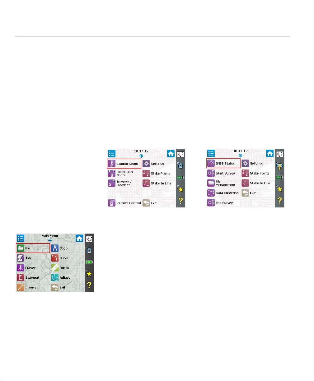
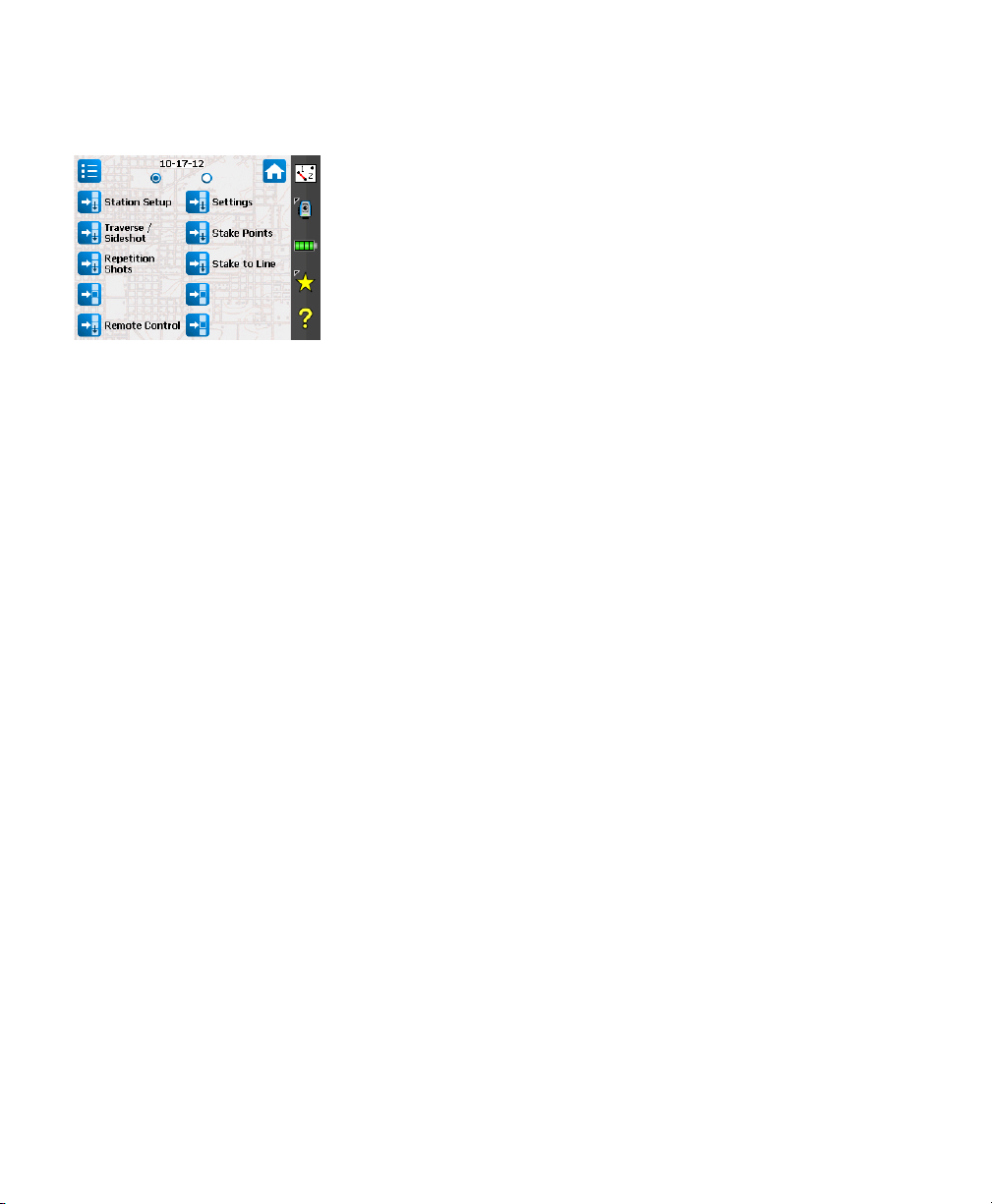
Because some of the available Survey Pro functions are mode dependent
(optical, GNSS), there is a different Home screen for each mode. That also
means there is a slightly different default Home screen depending on which
instrument is used. See below, from left to right: Optical, GNSS.
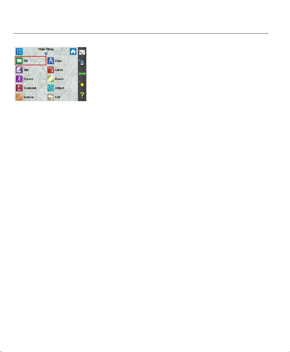
The functions available from the Home screen are taken from the Main Menu,
which contains all the possible Survey Pro functions.
You can access the functions available from each submenu by tapping the
corresponding submenu icon.
Each submenu, and all the functions attached to the submenu, are
represented by icons of the same background color. For example the File
submenu and its functions are all in green.
3
Page 12
Switching Between
Home Screen and
Main Menu
The table below lists the buttons allowing you to navigate between the Home
screen and the Main Menu and its submenus.
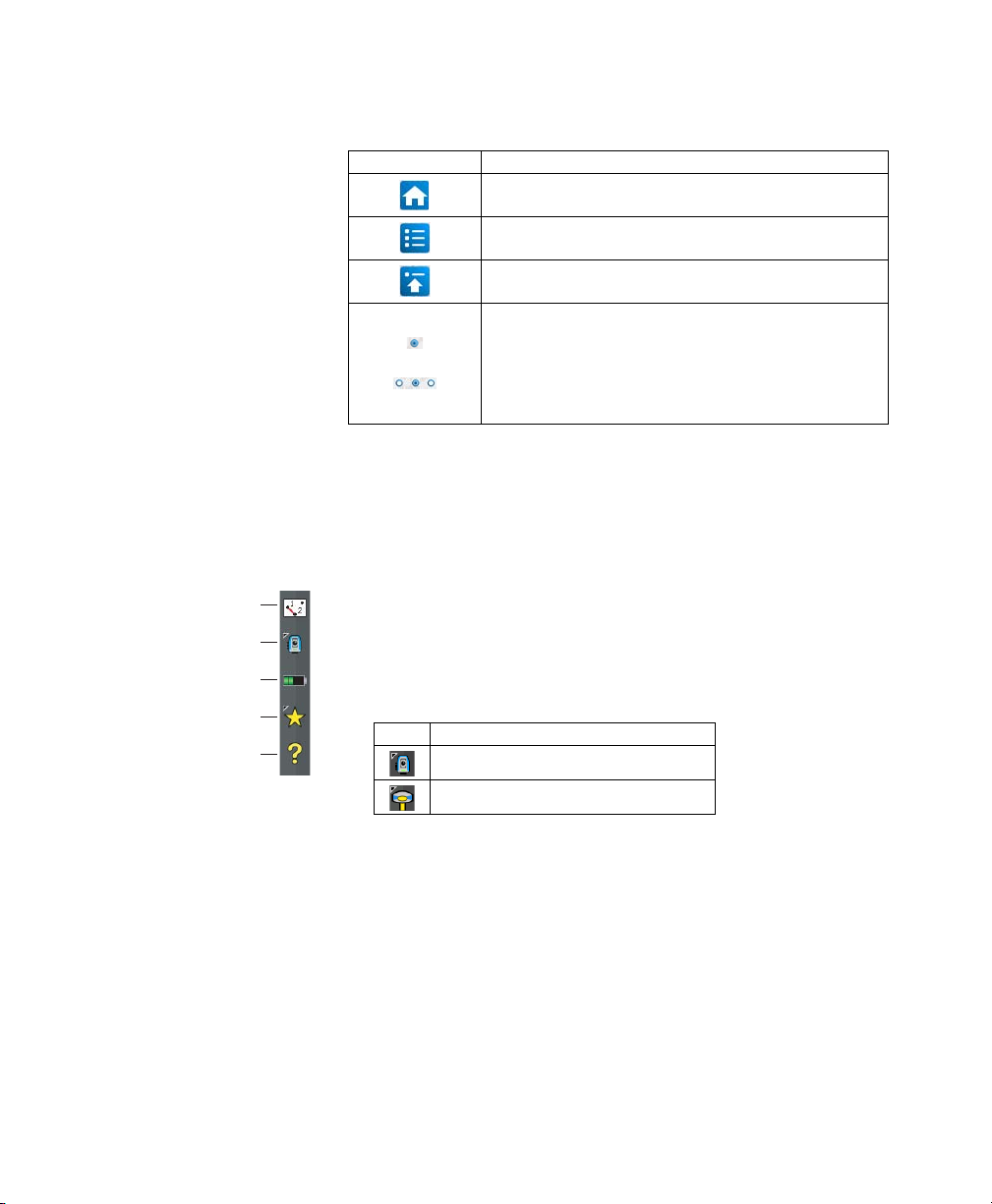
Icon / Check boxes Result
Takes you to the Home screen from the Main Menu or any submenu.
Takes you back to the Main Menu from the Home screen.
Takes you back to the Main Menu from an open submenu.
The default Home screen has only one page so there’s only one blue
dot (a radio button), and it is necessarily checked.
When adding functions through customization, other pages may be
created for the Home screen to accommodate all the added functions
(see How to Customize the Home Screen on page 5). In that case, tap
one of the radio buttons to display the desired page.
Command Bar
Description
[1]
[2]
[3]
[4]
[5]
The command bar is that portion of the Survey Pro screen that remains always
displayed whether the Home screen, the Main Menu or one of its submenus is
displayed. The command bar contains the following items:
• Map View [1]: This button will access the map view of the current job when
it is tapped. The map view is available from many screens (see Map View
on page 8).
• Instrument Used [2]: The Instrument icon indicates the mode (optical or
GNSS) that the software is in, and the type of instrument the software is
currently associated with.
Icon Current Instrument Selection
Optical instrument
GNSS receiver
This icon is also used to change the instrument and perform additional
settings on this instrument. See 4. Connecting Survey Pro to an Instrument
on page 18.
4
Page 13
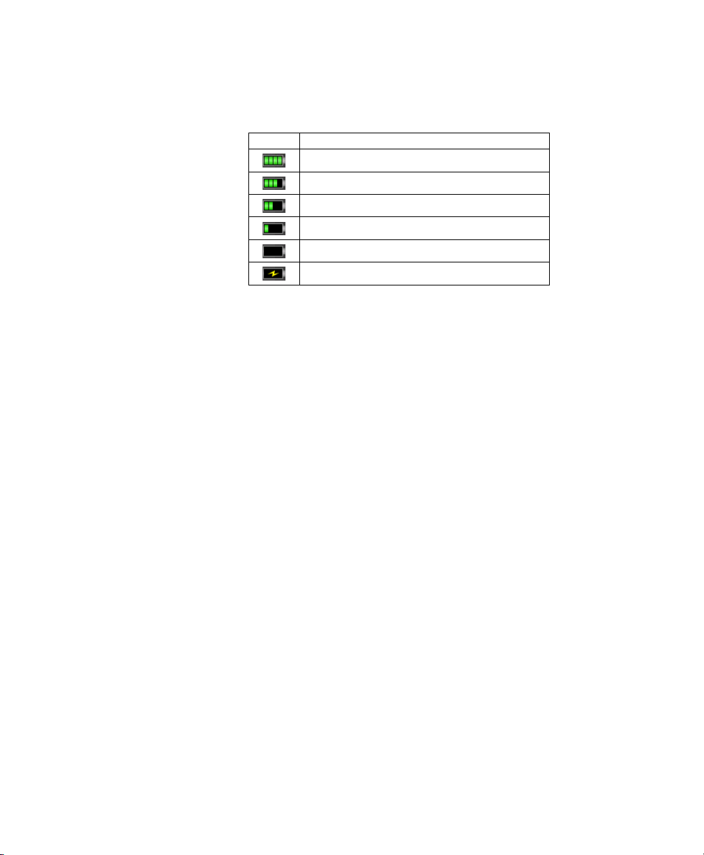
• Battery Level [3]: The battery icon displays the condition of the data
collector’s rechargeable battery. The icon has five variations depending on
the level of charge remaining, and a sixth variation to indicate battery
charging.
Icon Meaning
100% charge remaining
75% charge remaining
50% charge remaining
25% charge remaining
Less than 5% charge remaining
Battery charging from AC adaptor
Tapping the battery icon is a shortcut to the Windows Mobile Power
Settings screen.
• Quick Pick [4]: The Quick Pick button will open a customizable list of
routines. To quickly access a routine, just tap on it.
• Online Help [5]: This button opens the online help, which allows you to
access information for each screen.
How to Customize the
Home Screen
A message is displayed right after opening or creating a job asking you to “Tap
and hold on menu items to manage the Home screen”. This message prompts you
to customize the Home menu so that only the functions you will most
frequently be using in the field will be made available from this screen.
After you have become familiar with the customization process and next time
you launch Survey Pro, you can dismiss the message by checking the Don’t ask
this again prompt before tapping OK to close the message.
5
Page 14
Adding a Function
This is a three-step procedure:
• Go to the Main Menu, then to the submenu containing the function you
would like to add to the Home screen.
• Tap and hold the corresponding function item and select Ad d to Home.
Survey Pro then shows the Home screen with all the possible free locations
for the new function, all represented as unnamed icons. Note at this point
that all the icons are shown with the same background color (see example).
• Tap on a free icon (an unnamed one) or on the icon of an existing function.
The new function is inserted at the tapped location. Icon colors are then
restored.
If you tap on an existing function, this function and the next ones are
shifted down by one location. Survey Pro will automatically create a new
page of Home screen if the resulting number of functions on the screen is
greater that what the screen can accommodate.
Removing a Function
On the Home screen, tap and hold the function you want to remove and select
Remove Item. This instantly removes the function from the Home screen.
Moving a Function
• On the Home screen, tap and hold the function you want to move and select
Move Item. Apart from the function you want to move, which keeps its
original appearance, all other function items change color to blue.
• Tap on the location where you wish to move the function. This may be a free
location, or the location of an existing function. If you tap on an existing
function, the moved function will be inserted at the selected location and
the function at that location and the ones that follow will be moved down.
Home Screen Pages
The default home screen consists of a single page. You may add up to three
additional pages as part of the Home screen in order to make your many
favorite functions accessible from this set of pages.
• Adding a page is done by tapping and holding any function on the Home
screen and selecting Insert Page Before or Insert Page After.
• Switching from one page to the other is done by tapping on radio buttons
at the top of the screen.
• Removing a page is done by tapping any location on that page and selecting
Remove Page. This action requires user confirmation.
6
Page 15
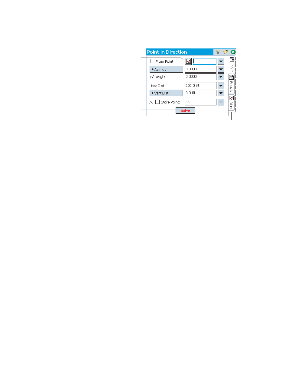
Screen Details The screen example below illustrates the different types of items you will
usually encounter on the screen when using the different Survey Pro functions:
[4]
[5]
[6]
[2]
[1]
[3]
[7]
• Input Field [1]: An area where you can enter a specific value.
• Output Field: Only displays a value that cannot be changed.
• Simple Button [2]: Typically used to run the function described by its
name. Just tap it to run the function. When the button name appears in red
characters, you can alternately press the Enter key on the keypad to
perform the same action.
• Power Button [3]: Typically used to provide context-sensitive functions to
modify the corresponding field. Once you have tapped on it, a drop-down
list will appear with several choices. Simply tap the desired choice from the
drop-down list.
• Choose From Map Button [4]: Always associated with a field where an
existing point is required. When the button is tapped, a map view is
displayed. To select a point for the required field, just tap it from the map.
NOTE: If you tap a point from the map view that is located next to other points,
another screen will open that displays all of the points in the area that was tapped.
Tap the desired point from the list to select it.
• Scroll buttons [5]: When a button label is preceded with the > symbol, it
indicates that the button label can be changed by tapping it, thus changing
the type of value that would be entered in the associated field. As you
continue tapping a scroll button, the label will cycle through all the
available choices.
• Check boxes [6]: Tap on these boxes to successively check or clear the
corresponding option.
•Tabs [7]: Many screens show tabs, which look like the tabs on index cards.
Tapping on a tab displays a subset of information part of the selected
screen.
7
Page 16
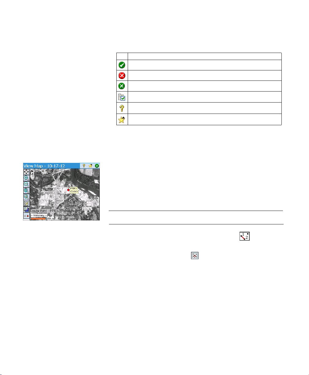
The following buttons will appear in the area usually occupied by the
command bar.
Item Function
OK button. Accepts the changes made and closes the window.
Cancels the changes made in the open window
Closes the current window
Quick access to the relevant Settings screen
Quick access to the Help system
Quick access to the Quick Pick list.
Map View The map view is a graphical representation of the objects in the current job. It
will show basemaps in the background if you are using one (see screen
example).
Basemap files may be either raster images (such as a georeferenced TIFF file,
or a JPG image with an associated world file) or CAD drawings (DXF files).
There are different map views depending on how the map view is accessed.
Each can display slightly different information, such as a vertical profile. A bar
is shown at the bottom of every map view that indicates the scale. The buttons
along the left edge of the screen allow you to change what is displayed in the
map view.
TIP: You can pan around your map by dragging your stylus across the screen.
The “main” map view is the one you get after tapping in the command
bar (from the Home screen or Main Menu).
From all those screens including a button, you will also display a map view
after tapping this button.
The “main” map view, as well as any map view accessible from a survey
routine, will also function as an “active” map. That means you can perform
several actions directly from the map. Tap and hold on the map to bring up a
context menu of available actions. The actions available will depend on what
you have selected at the tap-and-hold location.
8
Page 17
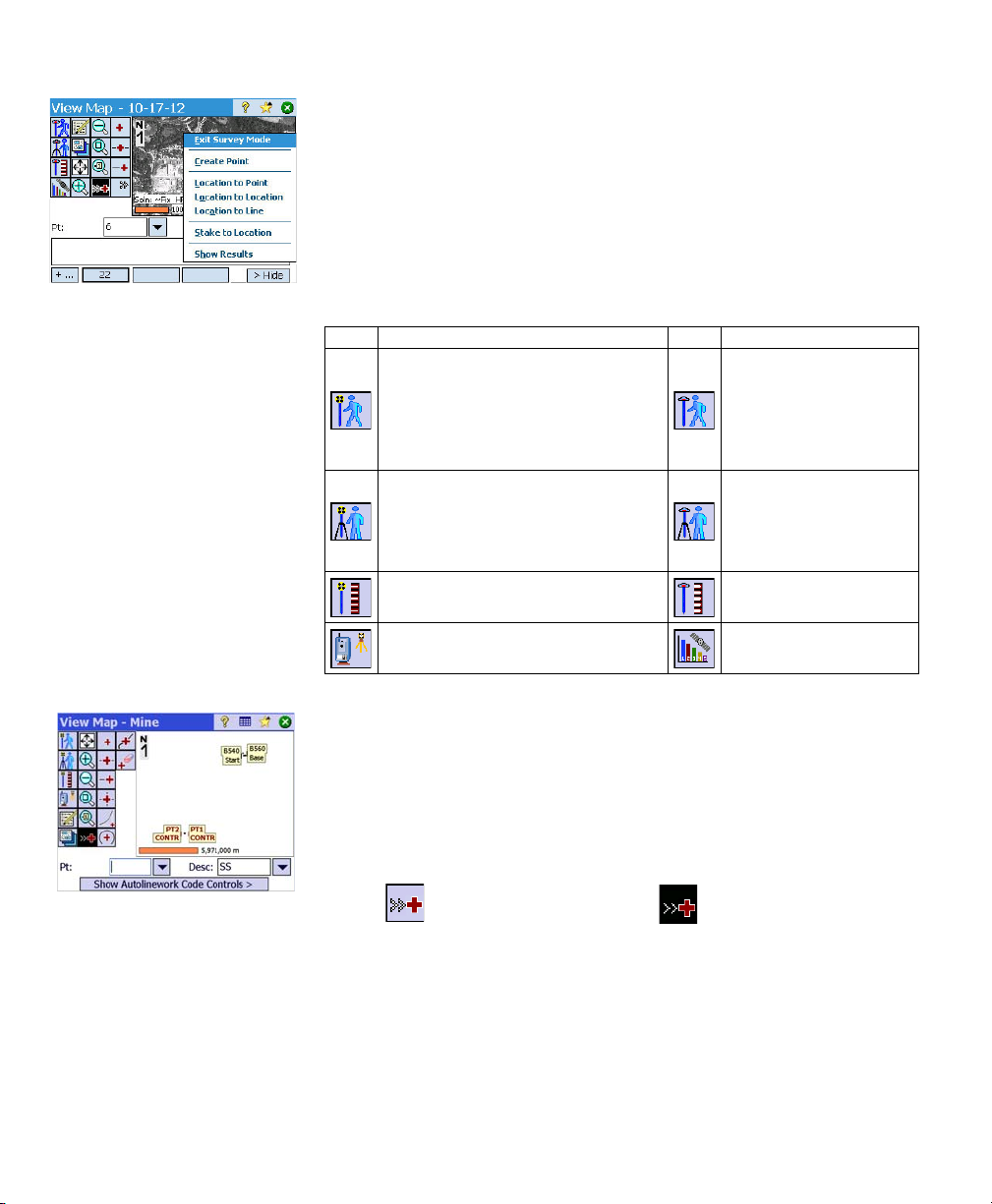
The main map can also function as an interface to collect measurements. Tap
and hold on the main map and choose Survey Mode to enable the Measurement
interface (see screen example for GNSS).
When in Survey Mode, you can collect data from the main map by tapping on
one of the available buttons (see table below).
You can also press the Enter key to trigger an observation. By default, the Enter
key will trigger a “Topo” observation. You can change the Enter key to trigger
a point observation by clearing the Survey Map Use Enter Button for Topo prompt
on the Job > Settings > Surveying tab.
Shortcut buttons are available to optimize your work. These are defined below:
Optical Function GNSS Function
- Mechanical optical instrument: Triggers the
instrument to take a shot in the current mode (fine
or coarse).
- Robotic optical instrument: Similar to GNSS, i.e.
takes the latest tracking mode data and stores a
point.
- Mechanical optical instrument: Takes a fine
mode observation.
- Robotic optical instrument: Opens up the remote
control screen where you will hit the Take Shot
button to take a fine mode observation.
Setting target height Setting antenna height
Station setup GNSS status
One-epoch point measurement
Multi-epoch point measurement
(static occupation)
The main map view includes two additional toolbars:
• The Zoom toolbar
• The Snap-To toolbar
These are described below.
Showing /hiding the two toolbars depends on the current survey mode status.
When the survey mode is inactive:
• The Zoom toolbar is always shown.
• Tap to show the Snap-To toolbar, to hide it.
9
Page 18
When the survey mode is active:
• Tap and select Show Snap To Options from the menu to show both the
Zoom toolbar and the Snap-To toolbar. Any of the zoom functions can also
be run directly from this menu.
• Tap to hide both of them.
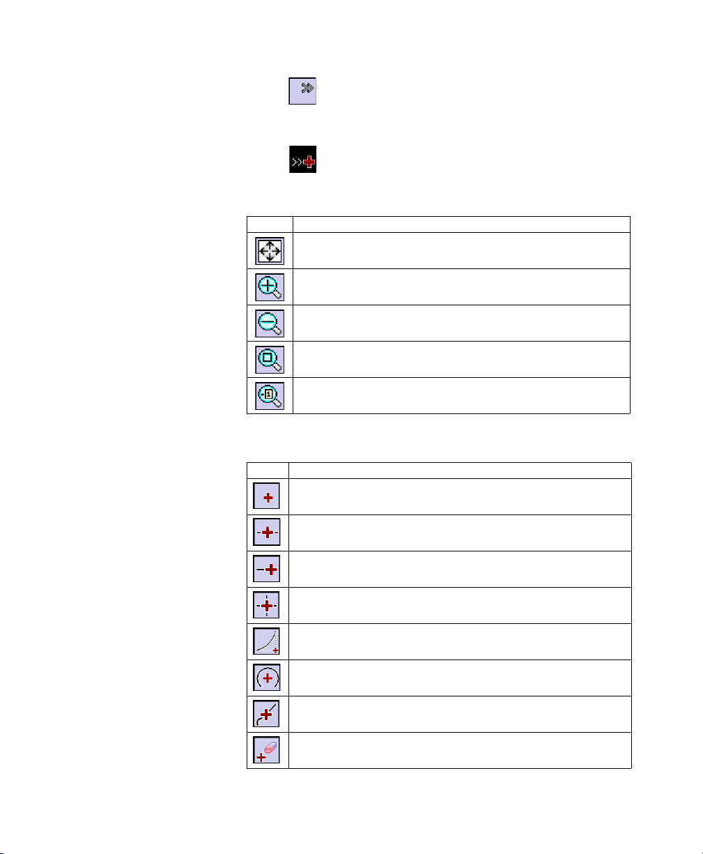
Zoom toolbar:
Button Function
Will change the scale of the screen so that all the points in the current job will fit on
the screen.
Will zoom the current screen in by approximately 25%.
Will zoom the current screen out by approximately 25%.
Allows you to drag a box across the screen. When your finger or stylus leaves the
screen, the map will zoom to the box that was drawn.
Prompts you for a point name and then the map view will be centered to the specified point with the point label displayed in red.
Snap-To toolbar:
10
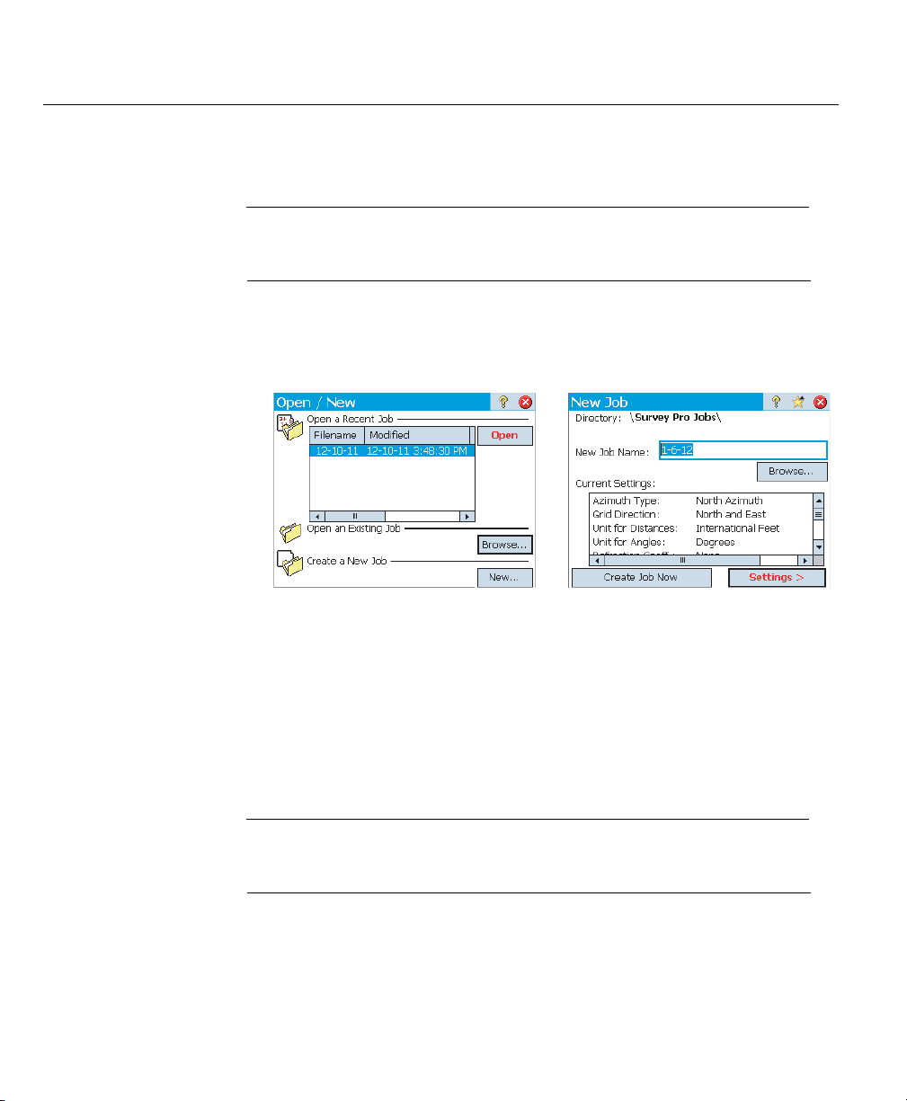
Button Function
Snap to nearby point.
Snap to the midpoint of the selected line segment.
Snap to the nearest of the begin point or the end point of the selected line segment.
Snap to the intersection of two straight line segments. You cannot snap to the intersection of line segments that are curves or spirals.
Snap to the point of intersection (PI) of the selected curve segment.
Snap to the radius point (RP) of the selected curve segment.
Snap to the nearest point on the selected straight line or curve segment.
Remove all of the Snap To temporary points created on this map.
Page 19
3. Creating a Job
12
Survey Pro cannot start without a job being open. Upon launching Survey Pro, the
Welcome to Survey Pro screen will guide you through the process of creating a new job
or opening an existing job.
NOTE: Upon launching the onboard version of Survey Pro, the initial screen allows you take
measurements without having to open a job. Refer to 8. Survey Pro’s On-Board Version on
page 67.
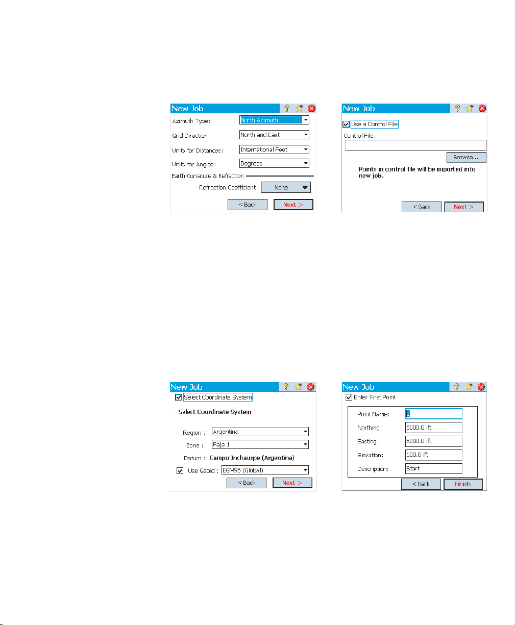
• Tap the New button. The New Job screen opens, which prompts you for a job name
where the current date is the default name.
• Either type in a new job name or accept the default name.
• You can create the job in two different ways:
1. Tap the Create Job Now button. The new job will be created with the current
default settings (as listed at the bottom of the screen) and will be stored in the
default directory (\Survey Pro Jobs\).
2. Tap the Settings button to access the different job settings (see below). After
you have gone through the different settings, tap the Finish button. This will
create and store the new job.
NOTE: The job names listed in the upper portion of the screen are those of the most recent jobs
you opened in Survey Pro. This list does not necessarily reflect the list of jobs stored in your data
collector. If you are looking for a job stored in your data collector, use the Browse button.
11
Page 20
Job Settings The settings and values entered for a new job become the default values for any
subsequent new jobs. A short description of the jobs settings is given below.
[1] [2]
• Units [1]: When creating a new job, set all the desired units for the job. You can
also enable the setting for Earth Curvature and Refraction correction for optical
measurements.
• Control File [2]: Control points can optionally be imported from another existing
job by checking the Use a Control File check box. After tapping Finish to create the
job, a message will indicate the number of imported points. If you are using a
control file, by default the coordinate system of this control file will be used for the
new job. You can override this default setting on the coordinate system page. A
control file can be imported from either a .Job or .Survey file.
12
[3] [4]
Page 21

• Select Coordinate System [3]: When you are using a control file, you can start the
job with the control file’s coordinate system, or you can pick a different coordinate
system from the database. If you don’t have a control file, you need to choose the
coordinate system for the job. To select the coordinate system for the new job:
– Clear the check box when you are doing an optical survey with a ground scale
factor of 1, or if you are doing a GNSS survey and there’s no known projection
or datum for your local grid coordinates.
– Check this box when your local grid coordinates are defined by some known
map projection and datum.
Understanding Scale Factor for your coordinate system:
– If your job has “no coordinate system”, Survey Pro automatically sets the scale
factor for optical measurements to “1.0”. This means that the distance
measured on the ground will be 1:1 to the distance on the grid. If you start a
GNSS survey, Survey Pro will use default Ground Calibration mode to calculate
your grid coordinates from GNSS measurements.
– If your job is using a map projection and datum, Survey Pro will automatically
calculate the correct scale factor for each station setup so the distance
measured on the ground will properly be reduced to the coordinate grid. If you
start a GNSS survey, Survey Pro will use the selected projection to calculate
grid coordinates from GNSS measurements.
NOTE: You can modify the default optical scale factor settings in the Job > Settings > Scale
Factor tab.
• First Point [4]: A default point name and coordinates are prompted to become the
first point in the job. You can freely change the name and coordinates of this point
before creating it. You may also clear the box if you do not want to create a new
point at this stage.
You may start your measurements now if you don’t need anything else in your job at
this time. In that case, go directly to 4. Connecting Survey Pro to an Instrument on
page 18.
If you need to add data (points, polylines, alignments, etc.) into your job before
starting, the sections below will tell you how to import or create/edit data from within
the open job. The last section lists the possible formats in which the data stored in
the job can be exported.
13
Page 22
Importing Data Use the File > Import function to add points to the open job. The points may be
imported from different file formats:
• Survey Pro native formats (*.Survey, *.JOB, *.JXL, *.CR5). JXL is the extension for
files in JobXML format, a Spectra Precision standard format for point, alignment,
and measurement data.
• LandXML (*.XML), an industry standard format for point, alignment, and
measurement data.
• Text format (*.TXT, *.CSV). An Import ASCII wizard will help you define the content
of every TXT file you will import.
Survey Pro will parse and import all the known elements from the chosen file. These
elements will be added to the current job as points, polylines and alignments. See the
definition of these elements in Editing Points on page 14, Editing Polylines on
page 15 and Editing Alignments on page 15.
The File > Import Control function is used to import points onto the control layer of your
job. Points on the control layer are protected from being modified. Control files should
be in *.Survey or *.JOB format.
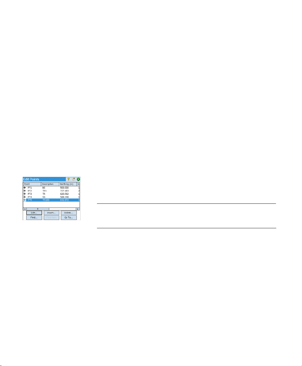
Editing Points A point in Survey Pro has coordinates and properties. A point’s coordinates can be
derived in one of two ways:
• Key-in point: The coordinates for this point were entered using the Job > Edit Points
function (Insert button) or this point was created by importing data to the job.
• Observed point: The coordinates for this point are calculated from measurements
in the current job.
14
NOTE: To see the current coordinates and properties of a point, you can tap the point on the
map. This will open the Point Details screen showing the Origin of the point, which describes
how the point was created.
You can use the Edit button of the Edit Points function to modify the description, layer,
picture and features of any single point. With a selection of multiple points, you can
use the same button to modify the description and layer of the entire selection.
Selecting several points not in sequence is obtained by first activating the Control key
and then tapping successively on the points to edit. The Control key is accessible from
either the virtual keyboard (CTL key on Nomad, Recon or ProMark 200) or the real
keyboard (CTRL key on Ranger). The Shift key can also be used to select several points
in sequence.
You can use the Edit button of the Edit Points function to modify the coordinates of any
key-in point in the job. The Location tab allows you to enter coordinates for the point.
You can enter Grid, global geodetic (WGS84 LLH) or local geodetic (Local LLH)
coordinates.
Page 23

• Grid: This point’s local grid coordinates are the Northing, Easting, Elevation values
that were keyed in or imported. This point’s global geodetic coordinates will be
calculated by transforming grid coordinates into latitude, longitude, height
coordinates using the current projection.
• Global geodetic: This point’s WGS84 coordinates are the latitude, longitude and
height values that were keyed in or imported. This point’s local grid coordinates
will be calculated by transforming geodetic coordinates into Easting, Northing,
Elevation coordinates using the current projection.
• Local geodetic: This point’s local geodetic coordinates are the latitude, longitude
and height values that were keyed in or imported. This point’s grid and global
geodetic coordinates will be calculated by transforming the local geodetic
coordinates with the current projection.
When there is no projection set or solved, there is no way to transform the keyed in
values into grid or geodetic coordinates. You will see these coordinates are missing
when you look at the point details.
If this point is derived from an observation, the Location tab will list its current
coordinates but these cannot be edited.
For more information on Descriptions, Layers and Features, see Appendix on page 73.
Editing
Polylines
Editing
Alignments
Exporting
Data
A polyline in Survey Pro is a line connecting points together. Each vertex of the line
is defined by an existing point, whether an observed or keyed in point. Points in
polylines can be connected with either straight segments or horizontal curves.
You can use the polyline editor to modify polylines (go to Job > Edit Polylines). The
polyline editor is described in the Online Help.
An alignment in Survey Pro is a line defined by vectors starting at a Point of Beginning
(POB). The POB can be an existing point in the job, or just location coordinates.
Alignments can have horizontal segments and optionally a vertical profile. Horizontal
segments can be straight segments, circular curves or spiral curves. A vertical profile
can be defined using a vertical curve and straight grade segments.
You can use the alignment editor to modify alignments (go to Job > Edit Alignments).
The alignment editor is described in the Online Help.
You can import alignments for staking, using Roads > Edit Roads menu. Alignments
imported using this function can be viewed in the alignment editor but cannot be
modified.
Use the File > Export function to export data from the open job to one of the supported
file formats. For most formats (Survey, JOB, TXT, CSV, XML, CR5 and DXF), you may
select the portion of the current job you wish to export. For export to Survey Pro 4.x
(Job/RAW) or JobXML format, the entire job database will always be exported.
15
Page 24
Generating
Survey Reports
Survey Pro can generate a report of your survey based on the content of the currently
open job and formatted according to the template you chose at the beginning of the
process.
Up to 18 templates are available (see list below) and most of them are customizable.
• Complete Survey Report, in html format
• Report in fbk format
• GNSS Points report in csv format
• Google Earth report in kml format
• LisCAD report in fld format
• Report in Nikon RAW format
• Optical observation report in htm format
• Two different points reports in csv format
• Nine different stakeout reports in csv or htm format
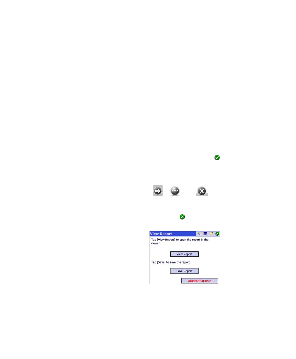
To generate, view, and save a survey report for the open job, follow the instructions
below:
• Go to the Main Menu and tap Job, then View Report.
• Select the desired template, then tap Next.
• Whenever prompted, customize the report, then tap to let Survey Pro generate
and then view the report.
• Depending on the chosen template, do the following to access the screen from
which you will be able to save the report:
– For html reports, tap , then . You then get the screen below.
– For Google Earth reports, in absence of an application capable of viewing the
generated report, Survey Pro will take you directly to the screen below.
– For all other types of reports, tap to access the screen below.
16
•Tap Save Report to save the report to the desired folder.
(On the same screen, the View Report button would take you back to the survey
report view, and the Another Report button would allow you to ask for a new report,
based on the same or a different template.)
Page 25
Sharing Files
Over the Internet
Survey Pro allows you to share files over the Internet. This requires that you first set
up an Internet connection on your data collector using Windows Mobile’s Settings >
Connections > Connections function.
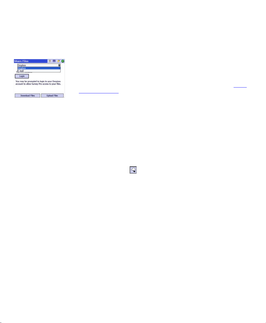
After the Internet connection has been established, go to File > Share and choose one
of the two options below depending on how you wish to share your files:
• DropBox, This option provides access to a web service that lets you post your files
in a shared folder. Using this service requires that you first create a DropBox
account and then you log in to it every time you open a session to upload or
download files. (The shared folder is in fact a remote folder that you can see
through the Internet connection.)
For more information on how to create an DropBox account, please refer to: https:/
/www.dropbox.com/. DropBox is a free service for volumes of shared data less than
2 Gigabytes.
• E-mail: Use this option to send e-mails to one or more recipients, with your files
attached to your e-mails. If several files are selected to be attached to an e-mail,
Survey Pro will automatically zip the files so there is always one single file attached
to the email.
Sending e-mails requires that you use an e-mail profile. You can set up your own
e-mail account (e.g. Gmail) or use one of the default e-mail profiles (SMS,
ActiveSync) set up by Windows Mobile. After you have set up your own e-mail
account, it will appear as an additional option in the E-mail Profile list.
The Share function can be called directly from many Survey Pro functions that
requires loading or saving a file (e.g. File > Save as).
Within these functions, tap to access the Share function.
17
Page 26
4. Connecting Survey Pro to an Instrument
Before you start taking new measurements in a job, you must tell Survey Pro
if an optical instrument or a GNSS receiver will be used to perform the job.
NOTE: Selecting an instrument only makes sense when Survey Pro is running on a data
collector. If it’s running in the instrument you are using (e.g. FOCUS 30), only this
instrument can be used in Survey Pro.
Before you make this choice, power on the instrument. This will allow the data
collector to detect it and establish a radio, Bluetooth or serial connection with
it when asked to do so.
With GNSS equipment, you may simply use a rover receiver, or both a base
receiver and a rover receiver. In the latter case, it’s good practice to start your
survey having both receivers running side by side. This way, you can complete
the setup of both receivers and ensure they are communicating on the data
link, and you are getting a fixed position at the rover.
When using a serial connection to start a base and rover, the data collector
must be connected to the base receiver first. Once the base is set, disconnect
the cable from the base and connect it to the desired rover.
Instrument Icon and
Options List
18
• Run Survey Pro.
• Open or create a job.
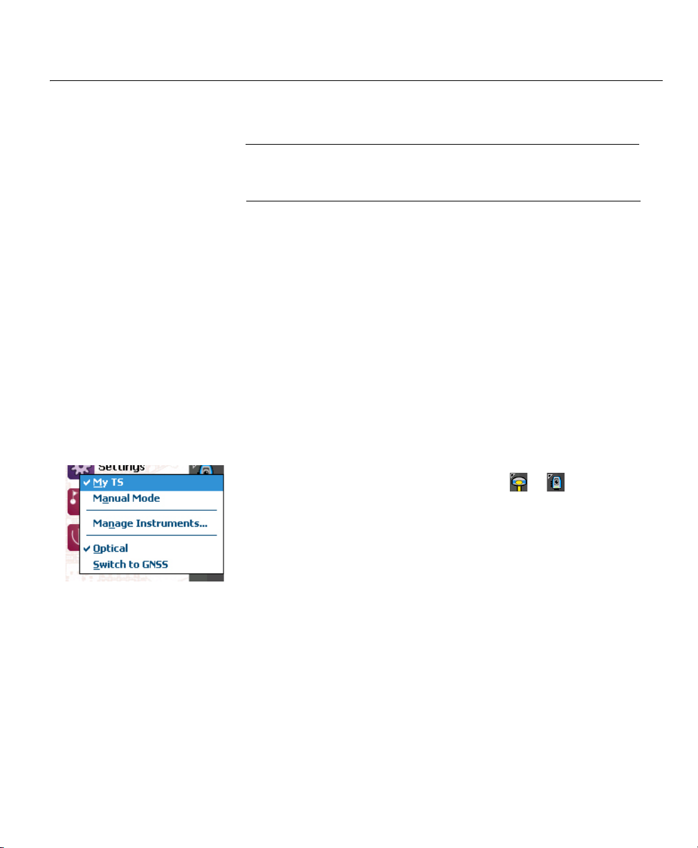
• Tap on the Instrument icon in the command bar.
(This icon may look like any of the following: or ).
This opens a list of options (see screen example).
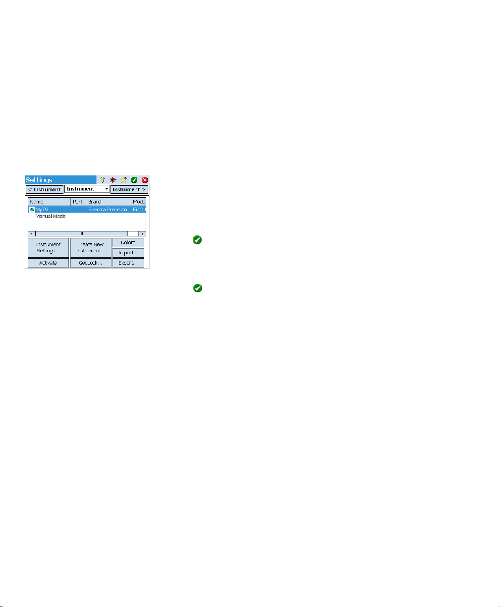
• Manage Instruments provides access to various functions allowing you to
declare a new instrument and make advanced settings for each instrument.
• The available options below the Manage In stru ments button are for selecting
the desired operating mode for Survey Pro:
– Optical for optical instrument (the selected one in the example)
– GNSS for GNSS receiver used in RTK or/and post-processing
• In the section above the Manage Instruments button is a list of all
instruments that have been added to Survey Pro for the currently selected
mode. The current active instrument is indicated with a check mark. An
additional option is available (“Manual Mode” for optical; “Demo Mode”
for GNSS) allowing you to use Survey Pro standalone, as if it were
connected to a real instrument.The ”Manual Mode” and “Demo Mode”
profiles cannot be deleted or renamed.
Page 27
In summary, tapping the Instrument icon allows you to:
• Select Optical or GNSS mode
• Quickly activate an instrument for use in the selected operating mode
• Quickly access the Instrument Settings screen
• Add a new instrument supported in the selected operating mode.
Connecting Survey
Pro to an Optical
Instrument
• Tap the Instrument icon and select Switch to Optical
• Tap the Instrument icon and select Manage Instruments. This opens the
Settings screen listing all the current instrument profiles.
• Tap the Create New Instrument button and define the new instrument: Choose
its brand and model, and then name it.
Depending on the model you select, additional settings may be required
(connection, radio, etc.) and status is also provided (port, connection, level
bubble, etc.). An Instrument Settings button is also available giving access
to advanced settings (collimation, EDM, lights, etc.).
• Tap to create the new instrument and close the Instrument Setup screen.
The new instrument is automatically selected in the list, as indicated by the
green spot shown before the instrument name. (You would use the Activate
button to activate another instrument after selecting it in the list.)
• Tap to close the Settings screen.
The Settings screen for optical instruments includes the following buttons:
• Instrument Settings: Gives quick access to the settings of the instrument
selected in the list. The type and number of settings depend on the brand
and model of the instrument selected. All instruments have a Precision tab
through which you can type in the expected precision values of the
instrument (angles, distances, PPM). These values are used in the
resection routine (see page 33) to weight the observations used in the
computation process.
• GeoLock: Allows you to enable or disable GeoLock, a GPS-assisted target
search function usable with some robotic instruments only.
• Export and Import: These buttons allow you to respectively save or load
instrument profiles. Survey Pro saves Instrument profiles as SPI files.
Importing an SPI file is a quick way of adding a preset instrument in Survey
Pro.
• Delete: Allows you to delete the instrument profile you select in the list.
19
Page 28

Remote Control Screen
If you are using a robotic total station, use the Survey > Remote Control function
to control the total station from the data collector running Survey Pro.
In addition to providing the same level of control as Survey Pro’s onboard
version, the Remote Control screen constantly provides information about:
• The charge status of the battery used in the total station
• The operating status of the total station (IDLE/ MEASURING/Locked)
• The quality of the radio link between the robotic total station and the data
collector.
The following buttons are also available from this screen to control the
instrument:
• GeoLock button: Launches a GPS-assisted search for the prism
• Search button: Launches a search for the prism starting at the current
instrument direction
• LockNGo button: Enables or disables the lock-and-go feature
• Stop button: Stops the current turn or search operation
• Turn To button: Opens up the “Turn To” screen where you can select a point
or angles to turn the instrument to.
The following icons are made available next to the title bar:
Item Function
Visible laser pointer off. Tapping on this icon will turn the laser pointer on.
Note: Standard safety precautions should be taken to ensure that persons do not look
directly into the beam.
Visible laser pointer on. Shown to indicate the visible laser is currently active. In the command bar, the instrument icon will then look like this:
20
Tapping will turn the laser pointer off.
Note: Standard safety precautions should be taken to ensure that persons do not look
directly into the beam.
Provides access to the Instrument settings screen.
Shows or hides the on-screen keyboard.
Provides access to Geolock activation, status and reset.
Page 29

Connecting Survey
Pro to a GNSS
Receiver
Introduction to Receiver Profiles
Survey Pro connects to a GNSS receiver through a receiver profile, which is a
convenient way of connecting to and configuring a GNSS receiver in one click,
using information previously saved as a receiver profile.
Receiver profiles allow you to use GNSS receivers for either RTK data
collection, post-processing data collection, or both simultaneously.
There are two ways of adding a receiver profile into Survey Pro:
•Using Spectra Auto-Configure. This procedure can only be used with Spectra
Precision receivers. Survey Pro uses Bluetooth to detect all the nearby
Spectra Precision receivers. For each detected receiver, Survey Pro will
offer to create a base, rover, and network rover profile using the default
settings for that receiver type. You can then choose the receiver profiles you
would like to create for the newly detected receivers.
•Using Manual Configuration. This procedure allows you to connect to a single
receiver either through a serial connection or over Bluetooth. This
procedure is suitable for any of the supported manufacturers and models
of GNSS receivers. Once the connection with the receiver is established,
you have to define your receiver profile by yourself (see Modifying a
Receiver Profile on page 25 for more information). In the last step, you will
name the receiver profile and save it.
NOTE: Adding a profile through one of these two procedures does not mean you
simultaneously set the receiver to operate according to this profile. Survey Pro just
identifies the type of the receiver so that it can prompt a default profile for this
receiver.
Example of Receiver Profiles List Later, when you start a survey, just select the desired receiver profile –and a
network profile if you are working in a a network; see also Managing Network
Profiles on page 26– before you ask Survey Pro to connect to the receiver you
are using. Survey pro will configure the receiver hardware according to the
settings defined in the selected receiver profile.
When you are using Bluetooth to communicate with receivers, you will typically
have a different profile for each receiver, since the Bluetooth address is part
of the profile. However, you can change the receiver a profile connects to by
changing the Bluetooth address.
You may have two or more different profiles for the same receiver. For example,
if you use receiver “x” as a rover with a radio base on some days, and as a
network rover with an NTRIP server on other days, then you would have two
different profiles for this same receiver.
Receiver profiles can be imported or exported as SPR files allowing you to
deploy consistent receiver profiles across your surveying crews.
Receiver profiles can be modified, renamed or deleted.
21
Page 30

Adding Receiver Profiles
• Tap the Instrument icon and select Switch to GNSS.
• Tap the Instrument icon and select Manage Instruments. This opens the
Settings screen listing the currently existing GNSS receiver profiles.
•Tap Add Receiver Profile, then use of the two procedures described below.
Example of Detected Receivers Adding Receiver Profiles Using Spectra Auto-Configure:
• Tap on the Start button in the Spectra Auto-Configure pane. Survey Pro then
scans automatically for new Spectra Precision GNSS receivers within
Bluetooth range. After a while, the screen lists the names of all the
detected receivers.
• Select each of the receiver for which you would like to add a receiver
profile.
Example of Selected Standard
Receiver Profiles
•Tap Next. Survey Pro will in sequence connect to each of the selected
receivers and will then return a list of standard receiver profiles, each of
them corresponding to a possible usable profile for that receiver.
• Check each of the receiver profiles you would like to add.
•Tap Finish. Survey Pro comes back to the Receiver Profiles screen on which
you can now see the added profile(s). Receiver profiles may be imported or
exported at this point (see Managing Your Receiver Profiles on page 23 for
more information).
• Tap to return to the Home screen.
Adding a Receiver Profile Using Manual Configuration:
Example of Serial Connection •In the Manual Configuration pane, do the following:
– Select the brand of your GNSS receiver
– Select the model of your GNSS receiver
– Select the type of connection to the receiver.
1) If it’s a Bluetooth connection, select Bluetooth and then tap the
Bluetooth Settings button. This button opens up the Bluetooth Instruments
screen, from which you can scan for Bluetooth devices supporting a
serial port service (or open up the Windows OS Bluetooth application).
Tap Start Scan and let the utility search for all the devices. When the
search is complete, select the device corresponding to your GNSS
receiver. Then tap Add Selected, change the Bluetooth name if you wish,
set the Bluetooth PIN if required,and tap .
Tap to return to the initial screen. The name of the chosen Bluetooth
device now appears in the Bluetooth Device field.
22
Page 31

NOTE: The Bluetooth Device field lists the names of the previously detected
Bluetooth devices. Use this field when the receiver you want to connect to was
detected beforehand, is still running nearby, or you know its Bluetooth name and
this name is still listed in the drop-down menu. Only in that case can you
directly select the Bluetooth name from that list and quickly establish a
connection with the receiver.
2) If it’s a serial connection, check Serial and select the port used on the
data collector side for this connection.
•Tap Connect. You can now define a receiver profile for use in the connected
receiver. Complete the four tabs (Survey, Modem, General, Reset). See
Modifying a Receiver Profile on page 25 for more information on receiver
profiles.
• Tap to save the new receiver profile. This profile is now available from
the list of receiver profiles. Receiver profiles may be imported or exported
at this point (see Managing Your Receiver Profiles on page 23 for more
information).
• Tap again to return to the Home screen.
Managing Your Receiver Profiles
Do the following to access the list of existing receiver profiles in Survey Pro:
• Tap the Instrument icon and select Switch to GNSS.
• Tap the Instrument icon and select Manage Instrum ents. Survey Pro lists the
receiver profiles as detailed below.
[3]
[4]
[2] [1]
[7]
[5] [6]
• [1]: Receiver profile name. By default, the name includes the receiver model
first, followed by its serial number (last four characters), then its survey
function.
23
Page 32

• [2]: Survey function icon: This may be one of the four icons below (see also
Modifying a Receiver Profile on page 25).
Icon Meaning
Rover.
Base.
Network Rover.
Network base.
• [3]: Connection icon: This may be one of the two icons below.
Icon Function
Shown when respectively a Bluetooth or cable connection has
been set between Survey Pro and the receiver.
If the Bluetooth icon is shown, tapping this icon will provide the
or
receiver brand and model as well as the receiver Bluetooth name.
If the Serial icon is shown, tapping this icon will provide the
receiver brand and model as well as the serial line settings.
• [4]: Settings icon: . Provides access to the receiver profile’s Survey,
Modem, General and Reset tabs. See Modifying a Receiver Profile on
page 25 for more information.
• [5]: Import. Tap on this button to import a receiver profile, then:
– Select the SPR file you want to import.
– Tap . Survey Pro returns the name of the receiver profile contained in
the file.
– Select the profile name to continue.
–Tap Import to complete the import sequence.
24
• [6]: Export. Tap on this button to export a receiver profile, then:
– Select the receiver profile you want to export.
–Tap Export.
– Name the file, then tap to export the profile and save it as an SPR
file in the chosen folder.
Page 33

Example of Receiver Information • [7]: This menu is displayed after you tap and hold a receiver profile in the
list. From this menu you can do the following:
– Receiver Info: Use this function to view more information on the receiver
connected to Survey Pro through this profile (see example). The possible
capabilities of a receiver (shown as icons) are identified below.
Icon Capability
The receiver has rover capability.
The receiver has base capability.
The receiver has data collection capability (for post processing).
– Rename: Used to rename the selected receiver profile.
– Delete: Used to delete the selected receiver profile. Then tap Yes to
confirm that you really want to delete the profile.
Modifying a Receiver Profile
Tap on the corresponding button in the receiver profiles list to make
changes to a receiver profile. The receiver profile is described on four different
tabs, the content of which is receiver-dependent.
IMPORTANT! All changes you make to a receiver profile will be effective only if a
receiver is connected to Survey Pro through this profile. In addition, the changes made
to a receiver profile will not be effective immediately in the connected receiver, but only
next time you start a survey using the modified receiver profile to connect to and
configure the receiver.
•The Survey tab is primarily used to define the following RTK survey
parameters:
Epoch 50’s Survey tab – Setup Type: Used to assign one of the four functions to the receiver:
1) Rover: Corrections received via radio.
2) Base: Corrections broadcast via radio.
3) Network Rover: Corrections received via a GSM modem.
4) Network Base: Corrections sent to an IP address.
– Elevation Mask: Limits the use of satellites to those that are high enough
in the sky, seen from the receiver antenna. All satellites located under
this zenith angle will be rejected (default: 10°).
– Corrections: Used to set the format of corrections received (rover) or
broadcast (base). This setting is not used for rover receivers that support
automatic detection of correction format.
– Use Station Index: Used to assign a station ID to a base, or identify the
base a rover is expected to use.
25
Page 34

– Set to Off mode: Sets the receiver idle, i.e. no more corrections are sent
out if the receiver is a base –or network base– or the receiver stops
listening for corrections if it’s a rover or network rover. There is an
exception with ProMark receivers, which in all cases will keep on
operating as rovers.
Epoch 50’s Modem tab • The Modem tab allows you to configure the RTK data link.
– If Setup Type = Rover or Base, allows you to enter the UHF radio settings
(i.e. baud rate, frequency channel and sensitivity for most radio
models).
– If Setup Type = Network Rover or Network Base, allows you to set the cell
modem used, either the one internal to the data collector (Current
Internet or Windows Networking option), the one internal to the receiver
(Internal GPRS Modem option), or an external cell phone (IP Modem
option).
Setting a cell modem mainly implies entering the service provider
information (APN) and your connection profile (username & password).
ProMark 800’s General tab • The General tab allows you to configure settings that are specific to the
brand and model of this receiver profile. For more information on brandand model-specific settings, see the online help.
• The Reset tab provides additional control over the connected receiver. Three
buttons may be available:
– Set Rx. to OFF mode: Same as Set to Off mode above.
– Soft Reset: Will reboot the receiver with its current settings.
– Hard Reset: Will reboot the receiver with its default settings (depends on
the model of receiver used).
26
Managing Network Profiles
Network profiles are managed the same way as receiver profiles. Network
profiles are required:
• To specify the source of RTK corrections a GNSS receiver acquires when it
is set as a network rover.
• To specify the destination of the RTK corrections a GNSS receiver will
generate when it is set as a network base.
Page 35

Example of Network Profile To add a new network profile:
• Tap the Instrument icon and select Switch to GNSS.
• Tap the Instrument icon and select Manage Instruments. This opens the
Settings screen listing the currently existing GNSS receiver profiles.
• Tap on the Networks tab
•Tap Add Network. Enter your network parameters (see below), then tap .
A network profile is defined by:
•A name
• An IP address
• An IP port
• A server type (NTRIP, Direct IP or Automatic)
• Additionally for Automatic or NTRIP server type, you need to set the Force
NTRIP password option. If this option is enabled, you will be prompted for
user name and password for every NTRIP mount point, even if the NTRIP
table specifies that they are not required. This option is to deal with poorly
formatted NTRIP tables, where the source table says that password is not
required, but the selected mount point actually requires one.
• Additionally for Direct IP server type, you need to specify the data format
of the corrections the network delivers.
When later starting a survey, you will be requested to specify the network your
receiver will work with. Choose the name of the network profile to specify this
network.
At this point, the Manage Networks button allows you to return to the list of
existing network profiles to make changes if necessary.
27
Page 36

Checking the GNSS Status
Checking the GNSS status of the connected receiver is recommended before
starting a job.This implies that the GNSS receiver is in real conditions of use,
preferably in an open sky environment.
Use the GNSS Status function on the Survey menu to read this information. The
GNSS status is split into six different tabs:
• Receiver: Provides additional information describing the position solution
computed by the receiver. In RTK, the Reset Ambiguities button allows you
to re-initialize the computation of the position. For more information, see
6. GNSS Surveying on page 41.
• Data Link: Describes how a rover is provided with RTK corrections, or the
type of RTK corrections generated by a base. For more information, see 6.
GNSS Surveying on page 41.
• Post Process: This tab is useful to help you conduct a Post Process survey.
The rest of the time, the tab is empty.
• Sky View: Provides a polar view of the sky showing the location and type of
each satellite being tracked (Lock) and the total number being used in
position solutions (see example). You may change the value of the elevation
mask on this screen. This will update the value read on the General tab as
well (see Managing Your Receiver Profiles on page 23).
• Sat Info: Shows the L1 signal strength (SNR) of each satellite in tabular and
graphic form. Depending on the receiver used, you may be given the ability
to reject some satellites you don’t want to use (because the signals received
from them are too weak for example, or because they are officially declared
unhealthy).
• Position: Provides the three coordinates of the position solution currently
computed by the GNSS receiver, the solution status, as well as heading and
speed if the receiver is currently moving. The position may be expressed in
WGS84 (always possible), in a local coordinate system (if selected and
solved) or as grid coordinates (if the grid is selected and solved).
28
Before going any further in your work, you should check that at least 6
satellites are received and used, each satellite providing a good signal level,
and the receiver delivers a 3D position solution.
Page 37

5. Optical Surveying
What you have done already:
• You have set up the optical instrument on a tripod over a point of your
choice and measured the instrument height.
• You have selected Optical from the instrument icon located on the Home
screen or Main Menu.
• You have activated the instrument for use with Survey Pro. See Connecting
Survey Pro to an Optical Instrument on page 19.
• You have configured the proper settings in the Job > Settings > Surveying tab.
This tab allows you to configure:
– Earth Curvature & Refraction correction: To adjust measured zenith angles
for the effects of earth curvature and refraction.
– PPM: To adjust the measured slope distances for the atmospheric effects
on the EDM.
– Survey with True Azimuths: Automatically sets the Circle on the
instrument to match the BS Azimuth that is set when pointed at the
backsight.
What you should do now: You have to position and orient the total station in
your local coordinate system before you start measuring points. This can be
done using one of the methods below, by choosing whichever is most
appropriate:
• Known Point: Station setup on a point with known coordinates.
• Unknown Point /Resection: Station setup on an unknown point using the
resection method to determine the position of the point.
• Use Last Setup: This method is made available only after a station has been
set up in the current job. Use it only if you are certain the tripod is still
exactly at the same location as when the last setup was performed, and the
same BS and Circle are being used.
The first two methods are described below. The point or points used should
have previously been stored in or imported into the job.
29
Page 38

Instrument Setup Station Setup on a Known Point
The name and coordinates of the known point where the station is set up can
be picked from within the open job. This method offers three different
scenarios:
• BS Azimuth [1]: Backsight azimuth. The station location will be set from the
coordinates of the known point. The circle is set using the value you enter
in the Backsight Circle field. The backsight azimuth will be the value you
enter.
Typically, this is an "assumed" backsight and the value will be 0 or North.
In most cases when using this method, the BS azimuth and the circle will
both be set at 0.
There are two variations on this, depending on whether the Survey with True
Azimuths setting is enabled or not. If it is enabled, then the circle will
always be set to what the BS Azimuth is. If not, then it's your choice what
to set.
• BS Point [2]: Backsight point. The station location will be set from the
coordinates of the known point. The station circle orientation will be set
from the azimuth between the station point and another known point
(backsight) in the job.
• New Point [3]: This is a variant of backsight azimuth in which the azimuth
is given to a new point you would like to measure and add to the job.
The diagram below illustrates the three possible scenarios.
30
[1]
Known Azimuth Direction
Known Station Point
[2]
Known Backsight Point
Known Station Point
[3]
New Backsight Point
Known Station Point
Page 39

Start the station setup as follows:
• Go to the Main Menu, then tap Survey > St ation Setup.
• Choose Setup Type= Known Point.
• Enter the name of the station setup point in the Occupy Point field. The
point name can be entered directly, or, picked from the map or point list
using the button.
• If you wish to ignore elevations in your job, check the 2D Survey box. You
will otherwise enter the HI (height of instrument) field.
•Tap Next.
Then, of the three possible options, choose the one that is suitable for your job:
1. If you choose BS Azimuth:
• Aim the instrument in the direction of a known or assumed azimuth.
• Enter the known or assumed value of azimuth.
• Enter the desired value of circle in this direction (typically “0” or the
true azimuth). If the Survey with T rue Azimuths setting is enabled, then
the circle value will automatically be set by Survey Pro.
•Tap Set Circle.
•Tap Next. The screen provides a summary of what you have just done and
prompts you to check the setup.
Check the Setup:
a. If you choose the By Angle option, just make sure the instrument is
still aimed in the direction of known azimuth, then tap Check. You
should read the previously set backsight circle.
b. If you choose the By Point option, enter the name of the point used
for checking, specify the target used on that point, correct the target
height if necessary and tap Check. A measurement is then made. Check
the delta values reported on the screen, which should be as close as
possible to zero.
c. You cannot use the By Distance option in this case.
• If you are satisfied with the read values, tap Finish. You can now start
measuring new points.
NOTE: Checking the backsight is an optional step that is enabled by default. If
you wish to skip backsight checks after station setup, you can turn this off in
the Job > Settings > Surveying tab.
31
Page 40

2. If you choose BS Point:
• Enter the name of the backsight point. It can also be picked from the
map or the list of points.
• Specify the type of target used at the backsight point (Fixed Target or
Roving Target).
A “roving target” is when you measure to the backsight with the same
rod and prism you will be using for your subsequent data collection.
A “fixed target” is when you have a tripod and prism that will remain at
the backsight and that will be different from the rod and prism you will
be using for subsequent data collection. See also Managing Smart
Targets on page 75 for more information on the Survey Pro target
database and the fixed backsight target.
• Using , select the name of this target. As a result, the HR (height of
rod) field is updated to provide the height of this target.
• Aim the instrument at the known backsight point.
• Enter the desired value of backsight circle in the direction given by the
backsight point (typically “0” or the true azimuth). If the Survey with True
Azimuths setting is enabled, then the circle value will automatically be
set by Survey Pro.
•Tap Set Circle.
•Tap Next. The screen provides a summary of what you have just done and
prompts you to check the setup.
As previously explained for BS Azimuth, you can in the same way check
the setup either By Angle or By Point (see Check the Setup above).
You can also use the By Distance option. Just make sure the instrument
is still aimed in the direction of the backsight point and tap Check. The
measured horizontal and vertical distance errors are reported on the
screen. They should be as close a possible to zero.
• If you are satisfied with the read values, tap Finish. You can now start
measuring new points.
32
NOTE: Checking the backsight is an optional step that is enabled by default. If
you wish to skip backsight checks after station setup, you can turn this off in
the Job > Settings > Surveying tab.
Page 41

3. If you choose New Point:
– Place a target at the unknown (new) backsight point.
– Aim the instrument at this point.
– Enter the known or an assumed value of azimuth along this direction.
– Enter the desired value of backsight circle for this direction (typically
“0” or true azimuth). If the Survey with T r ue Azimu ths setting is enabled,
then the circle value will automatically be set by Survey Pro.
–Tap Set Circle.
– Specify the type of target used at the backsight point (Fixed Target or
Roving Target).
– Using , select the name of this target. As a result, the HR field is
updated to provide the height of this target. Update the height value if
necessary.
–Tap Measure Backsight.
– After making sure the instrument is sill pointed at the backsight point,
tap OK.
– Enter a name and description for the new backsight point.
– Tap to measure and store the point.
–Tap Finish. You can now start measuring new points.
Station Setup on Unknown Point, Resection Method
The resection method is illustrated below.
PT1
PT3
PT4
At least two known points should be observed to solve the station setup (e.g.
PT1, PT2). Other known points (PT3, PT4,..) may be added to refine the
computation.
PT2
33
Page 42

• Go to the Main Menu, then tap Survey > Station Setup.
• Choose Setup Type= Unknown Point/Resection.
•Use the Store Pt and Description fields to enter respectively the name and
description of the point where the instrument is set up. (This is a new point,
with unknown coordinates.)
• If you will ignore elevations in your job, check the 2D Survey box. You will
otherwise enter the height of instrument in the HI field.
• You can take one or more shots of each point. Enter the desired number of
shots in the Shots per Resect Point field.
• You may want the instrument to perform either Direct and Reverse
measurements (recommended for station setup) or a Direct Only
measurement. Use the Sequence field to make this choice.
•Tap Next. This opens the St ation Setup screen on which you should define
the following parameters:
– Resect Point: Enter the name of the first point used (PT1 for example).
– Option: Define the type of measurement you will perform on the point
(Distance and Angle or Angle Only).
– Define the type of target used and its height (HR).
•Tap Observe then Take Shot to start a measurement. You are then taken back
to the Station Setup screen where the measured point is listed as the first
point involved in the station setup.
• Repeat the previous two steps for the next point (PT2 for example), and
then for additional points (PT3, PT4, etc.) for data redundancy.
As you get new points, Survey Pro tries to compute a solution for the station
location.
When a solution is available, the RMS values of the solution are shown in
the lower part of the screen. If not a good contributor to the solution, any
measured point may be removed from the process by clearing the
corresponding check box. You will immediately see the impact of this point
removal on the quality of the solution.
Likewise you may reject the horizontal or vertical contribution of a point by
tapping on the corresponding “Yes” which will then be changed into a
blank field. Again, you will immediately see the impact of this change on
the quality of the solution.
• When you are satisfied with the results, tap Next. The screen then shows
the properties of the station setup. If you scroll down the list of results, you
will see the components of the final error ellipse for the solved point.
On this screen, Survey Pro defines one of the control points you have just
used in the resection method as a backsight point.
34
Page 43

• At this stage, you can tap Finish to complete the station setup. The
instrument circle used for this setup will be the direct circle reading on the
first resection point used in the setup, unless you are surveying in true
azimuth mode.
In true azimuth mode, the instrument circle will be adjusted so that your
circle will now read the true azimuth when pointed at the first resection
point used in the setup.
Alternatively, you can tap Backsight to proceed to the normal backsight
setup, with your newly calculated station point as the setup point, and your
last resection point as the backsight point. It is a good practice to do a
backsight check after a resection to ensure the instrument circle is oriented
as you expected.
When this is done, tap Finish. You can now start measuring new points.
Variants to the Basic Station Setup Procedures
There are variants to the basic step-by-step procedures described above,
related to your current job settings (in Job > Settings > Surveying tab):
• Check Setup: You may shorten the BS Azimuth and BS Point routines by
checking the Skip check during Station Setup option.
• PPM Correction: By default, the PPM will not show up in the station setup
routine. But, if you check the box for Prompt for PPM during Station Setup, the
PPM will become the first step in your station setup routine.
The PPM correction is applied to all measured slope distances. This may
be achieved in one of two different ways:
1. You enter the PPM in the instrument which in return will provide Survey
Pro with slope distances corrected for the PPM.
2. Or you enter the PPM in Survey Pro, in which case the instrument will
return uncorrected slope distances (make sure the PPM is set to “0” in
the instrument). Survey Pro will apply the PPM correction to any slope
distances that will be used in further calculations.
NOTE: With some instruments (e.g. FOCUS 30 and S6), the PPM correction can
only be set using the second method.
For any station setup, you can also set the elevation of the station point
independently using the Remote Elevation routine (see Remote Elevation on
page 36).
35
Page 44

Remote Elevation
This routine will set the elevation coordinate of the station from a point with
known elevation. It is accessible from within the first station setup screen by
tapping the Remote Elevation button (provided the 2D Survey box is unchecked).
The point with known elevation is either:
• A point stored in the job. You will select it from the map or the list of points.
• A point not stored in the job, but its elevation is known, perhaps through
past results, by calculation, or printed on a data sheet.
Step-by-step procedure:
• Have a target set up on the point.
• Aim the instrument at the point.
•Go to Station Setup and then tap the Remote Elevation button.
• Enter the elevation according to the suitable method.
•Check the HI value.
• Select the target and check the HR value.
•Tap Take Shot.
Point Measurement Introduction to Traverse / Sideshot
•Tap Survey > Traverse / Sideshot. This screen allows you to make traverse and
sideshot measurements. It also provides access to the station setup via the
Backsight button allowing you to either check the current setup or start a
new setup. The current setup is summarized at the top of the screen.
• Enter the name (Foresight) and description (Desc.) of the point you will now
be measuring, as well as the type and height (HR) of the target used on that
point.
• The next step is choosing between sideshot or traverse.
Choosing “Sideshot” means you simply want to take a measurement of the
point. (See Sideshot on page 37.)
Choosing “Traverse” (see illustration below) means you are expected to
move the instrument to that point either immediately or after measuring
other points (sideshot).
36
[1]
PT1 PT2
Instrument Target
This implies a new station setup is required after moving the instrument.
(See Traverse on page 38.)
[2]
PT1 PT2
InstrumentTarget
Page 45

Sideshot
[1] [2]
• Be sure the instrument is pointed at the target placed over the point.
•Tap Sideshot. Survey Pro returns the results of the measurement in the
lower portion of the screen ([1]). The point name is automatically
incremented for the next measurement. Tapping on the Result tab will
provide more information on the measurement made ([2]).
Point: Point name
N: Point coordinate Y
E: Point coordinate X
Elev.: Point coordinate Z
Description: Point description
Angle Right: Azimuth angle measured from the occupy point to the foresight
point (measured in a horizontal plane)
Zenith: Zenith angle measured from the occupy point to the foresight point
(Zenith is measured in the vertical plane, relative to gravity, where 0 is
pointing straight up, parallel to gravity, and 90 is pointing straight ahead,
orthogonal to gravity.)
Slope Dist: Slope distance measured from the occupy point to the target
Horz Dist: Horizontal distance calculated from the occupy point to the target
Vert Dist: Vertical distance measured from the occupy point to the target.
• Repeat the above two steps until all your points have been measured.
37
Page 46

Traverse
• Be sure the instrument is pointed at the target placed over the point.
•Tap Traverse. The screen prompts you to measure a new point, or to pick a
point that was previously measured from the current station setup (Survey
Pro will display a list of appropriate points), and then move the instrument
to that point. If you create a new point to traverse to, you will then be asked
to enter the description of the point before measuring it.
• After the measurement is done or the point selected, Survey Pro provides a
summary of what the new station setup will be (see [1] below).
• Move the instrument to the new station point and level it on its tripod.
• Measure the new instrument height and enter the measured value (HI).
• Aim the instrument in the direction of the point you came from (now the
backsight point).
• Enter the type and height (HR) of the target used on the backsight point
(see [1]).
[1] [2]
38
•Tap Send Circle to set the circle. The New Backsight Circle will be preset to
zero, unless you are surveying with true azimuths.
In the true azimuth case, the circle will be the azimuth from the new
location occupied by the station back to its previous location, which is now
your backsight point.
•Tap Next and complete the station setup as you would normally do using the
Known Point (backsight) method (see [2]).
NOTE: The Station Setup routine can be used at any point to occupy any existing
point in the job at any time. It is up to you to determine if and when this is
appropriate.
Page 47

Repetition Shots
The Repetition shots function allows you to perform sideshots or traverse shots
using any number (between 1 and 99) of repeated measurements (“Sets”).
• Go to the Survey menu and tap Repetition Shots.
• Tap in the command bar to access the job settings relating to repetition
shots (equivalent to navigating to the Job > Settings > Repetition tab).
•Tap the Repetition tab. The Rep Shoot Sequence field allows you to choose the
desired sequence of repetitions (7 available):
– “FS” stands for “Foresight”:
– “BS” stands for “Backsight”
– The ">" symbol is used to denote the next shot coming in the sequence
using the same face of the instrument (direct or reverse).
– The "^" symbol is used to denote when in the sequence you will flip the
instrument to take observations in the opposite face.
The other parameters on this screen are self-explanatory. Set them to meet
your application. The Radial Sideshot Seq field allows you to specify the
sequence of observations to be taken in the Radial Side Shot routine. This
setting is NOT used for either regular repetition shots or multiple side
shots.
• Tap to return to the Repetition Shots window.
•Use the Foresight field to enter a name for the point you will measure
through repetition shots.
• Enter the number of Sets you want the sequence to be repeated.
• Select the type and enter the height (HR) of the target used on the foresight
point.
• Start the sequence by tapping either HA, ZA, SD or All, whichever is
appropriate in your case. Depending on the instrument used, run the series
of measurements manually or let the instrument do this automatically.
Results are displayed at the end of the sequence (see illustrated).
– Average of: Shows the average angle or distance to the point from all the
shots taken. The number in parenthesis is the total number of
repetitions performed.
– Worst Residual: Displays the worst residual calculated from all the sets
of the selected measurement type.
You may use one or more of the Toss buttons to remove from the solution
the set of measurements that provided the worst residual. A Toss button can
only be used if three or more sets have been collected.
When you tap HA, ZA, SD or All, Survey Pro will collect an additional
observation of that type (or all of them) and add it to the sets already
collected.
39
Page 48

EXAMPLE: If you had three complete sets, then selected to toss the worst HA, you
would now have two HA sets, three ZA sets and three SD sets. If you tapped HA, you
would collect an additional set of horizontal angles only, and on return to this screen,
you would now have three HA, three ZA, and three SD sets. If you hit HA again, on
return to this screen you would have four HA, three ZA and three SD sets.
• Additionally from this screen, you can either traverse to the point (tap
Traverse and then follow the usual traverse procedure) or tap Sideshot to
store a measurement of the point, based on all the data gathered during the
repetition shots, to store the point with the measurements taken.
NOTE: The Sideshot or Traverse buttons will not become active unless at least one
observation for each type of measurement (HA, ZA, SD) has been performed.
If you tapped Sideshot, the observation is used to store a new point, and you
view the results (see example). If you tapped Traverse, the traverse prompt
will open and you will be guided through moving and setting the instrument
on the new occupy station point. The traverse procedure is described above
(see Traverse on page 38).
Tap Sideshot if you plan to occupy the measured point at a later time. You
can use the Traverse button later to initiate moving the instrument to any
point measured from the current station.
Tap to quit the Repetition Shots function.
40
Page 49

6. GNSS Surveying
Starting an RTK Base NOTE: You don’t need to set up a base if you are working in a network. Just make sure
your rover is configured to receive network corrections, and actually receives them
before you start taking measurements in your job. See Starting an RTK Rover on
page 43.
What you have done already:
• You have set up the base GNSS receiver on a tripod over a point of your
choice and measured the antenna height.
• You have selected GNSS from the instrument icon located on the Home
screen or Main Menu.
• You have created a receiver profile that matches the use of your receiver as
a base (or network base) and the receiver has been reported as being
“base” capable. See Connecting Survey Pro to a GNSS Receiver on
page 21.
• You have made sure the GNSS status is correct at the location where the
base is to be operated. See Checking the GNSS Status on page 28.
What you should do now:
• Go to the Survey menu and tap Start Survey. You may also find the Start
Survey function on your Home screen.
• Unless already done, highlight the name of the receiver profile you intend
to use for operating your base.
For a “network base”, select the network to which the base will deliver its
corrections by selecting the relevant network profile name. For a “base”,
there may be additional settings required using the Configure Modem button
(the radio settings provided by the selected receiver profile may not match
your case of use).
•Tap Connect.
When creating a job, if you decided not to choose a coordinate system, you
will be asked to reconsider this choice when starting the base. The Start
Survey Prompt Projection screen will appear at this time with two possible
options:
1. Ground Calibration: Choose this option if there is no known projection or
datum to relate your local grid coordinates to geodetic coordinates
(through this choice, you confirm your decision to use local control to
set up a coordinate system). The selection of a geoid is possible after
making that choice.
41
Page 50

2. Mapping Plane: Tap on this button if you now wish to use a coordinate
system (i.e. known origin and type of projection + known datum) that
can either be keyed in or picked from Survey Pro’s coordinate system
database. For more information on the projection mode, refer to
Introduction to Calibration on page 52.
NOTE: If you always start your GNSS surveys with the same type of projection
mode, then you can tap Don't ask me agai n at this prompt, and Survey Pro will
start the GNSS survey with the settings you used to create the job.
• Survey Pro will poll for the base position. While Survey Pro does this, enter
the antenna height you measured previously (Measured field) and how you
measured it (To field).
You may ask the base to log raw data (for post-processing) by just specifying
a recording interval in the Post Processing Recording Interval field. When you
start a rover, by default it will automatically use the same recording interval
as the base you set. Set the recording interval to “Off” if you do not want
to record raw data.
•Tap Next. Survey Pro searches the point database for a location that
matches the current base position (the one that was checked on the
previous screen). If a matching point is found in the job, or else in the
reference station database (see Managing Reference Stations on page 57),
then Survey Pro offers this as the default base point. Tap Change to choose
a different point or to create a new point for the base setup.
•Tap Next. The base is now started. Survey Pro prompts you to start the rover
(as if you had tapped Start Survey on the Home screen). Underneath the
GNSS receiver profiles list, the name of the modem for the selected profile
is displayed).
42
NOTE: if you only want to set the base at this time, tap . Survey Pro will then exit
the Start Survey wizard and open the GNSS status page connected to the base.
Page 51

Starting an RTK Rover This section describes how to configure and start an RTK rover.
What you have done already:
• You have set up the GNSS receiver on a pole and measured the antenna
height.
• You have selected GNSS from the instrument icon located on the Home
screen or Main Menu.
• You have created a receiver profile that matches the use of your receiver as
a rover (or network rover) and the receiver has been reported as being
“rover” capable. See Connecting Survey Pro to a GNSS Receiver on
page 21.
• You have made sure the GNSS status is correct where you start your survey.
See Checking the GNSS Status on page 28.
What you should do now:
• Go to the Survey menu and tap Start Survey. You may also find the Start
Survey function on your Home screen.
• Unless already done, highlight the name of the receiver profile you intend
to use for operating your rover.
For a “network rover”, select the network from which the rover will receive
corrections by selecting the relevant network profile name. For a “rover”,
there may be additional settings required using the Configure Modem button
(the radio settings provided by the selected receiver profile may not match
your case of use).
•Tap Connect.
When creating a job, if you decided not to choose a coordinate system, you
will be asked to reconsider this choice when starting the survey (unless you
started your own base and you were already prompted to make a choice at
that time). The Start Survey Prompt Projection screen will appear at this time
with two possible options:
1. Ground Calibration: Choose this option if there is no known projection or
datum to relate your local grid coordinates to geodetic coordinates
(through this choice, you confirm your decision not to use any known
coordinate system). The selection of a geoid is possible after making
that choice.
2. Mapping Plane: Tap on this button if you wish to use a coordinate system
(i.e. known origin and type of projection + known datum) that can either
be keyed in or picked from Survey Pro’s coordinate system database. For
more information on the projection mode, refer to Introduction to
Calibration on page 52.
NOTE: If you always start your GNSS surveys with the same type of projection
mode, then you can tap Don't ask me again at this prompt, and Survey Pro will
start the GNSS survey with the settings you used to create the job.
43
Page 52

• While the rover receives data (corrections and position) from the base, enter
the rover antenna height you measured previously (Measured field) and how
you measured it (To field).
You may ask the rover to log raw data (for post-processing) by just
specifying a recording interval in the Post Processing Recording Interval field.
If you earlier set up a base doing the same, then make sure you are using
the same recording interval for both receivers. Select “Off” if data logging
is not required.
•Tap Next.
• Confirm or change the point where the base is located.
For most receivers, the height of the base antenna is broadcast over the
data link, so you do not need to change the base antenna height displayed
on this page.
NOTE: The broadcast height will be reduced to the antenna phase center, and will
show as an “Unknown” antenna brand.
If your rover receiver does not get the base antenna height from the data
link (Measured= ”0.000”, Base Brand= “Unknown” and Antenna Type=
“Unknown Broadcast”), you need to specify the antenna brand and type
used at the base, enter the measured height and specify the mark used to
measure the height (tap on the Change button to access the base’s Antenna
Height definition screen).
NOTE: Next time you run your rover, Survey Pro will automatically query the Base
Info list (see Managing Reference Stations on page 57) for the suitable base to use
with the rover, thus skipping the base location selection step described here.
If both the base location and antenna type match, Survey Pro will automatically use
the antenna parameters stored in the Base Info list for that base, and not the
antenna parameters broadcast by the base.
The message Rover is read y to s et wi t h r ef er en ce s t ati o n “ x”. will indicate that the base
was picked from the reference station data base, whereas the message Rover is ready
to start a survey with base point ‘x’. will indicate it was found in the survey file.
Any time a VRS (Virtual Reference Station) survey is started, excluding a PRS
(Physical Reference Station) in a VRS survey, automatic base selection will be done
as well. The message Rover is ready to start a su rvey with virtual base ‘x’ will be displayed
in this case.
44
• If the Finish button is displayed, this means the coordinate system is fully
solved, and you are ready to collect data.
Page 53

If the Next button is displayed instead, this means you are working in
Default Ground mode, where a calibration is always required, or you are
working in mapping plane mode but you started your base on a new point
with a new autonomous position. Tap this button. You will see a new screen
asking for occupation of control points (see screen example).
For the sake of clarity, calibration is discussed in a separate section (see
Solving Calibration on page 52).
NOTE: Solving the calibration is optional when your coordinate system is a known
map projection and datum, and your base was setup on a known point.
At this stage, you may tap Start Now to begin surveying with a temporary
calibration solution, which will solve your translation, but the scale and
orientation parameters will remain unknown. You can collect data points;
their local coordinates will be calculated with this temporary calibration.
At any time during the survey, you can collect the required number of GNSS
control points and solve the proper calibration for your site. After you solve
the calibration, any data collected points will automatically be recalculated
using the latest solution of coordinate system.
Some routines, such as point stakeout or offset points, cannot be run until
the calibration is properly solved.
• Before starting data collection, tap in the command bar. This directly
opens the Meas. Mode tab (part of the Job Settings screen) where you can set
the acceptance criteria for different types of point collection:
–On the Data tab, define the criteria for all the points you will collect
using Point from the Data Collection screen or from the active survey map.
–On the Topo tab, define the criteria for all the points you will collect
using Topo SS from any measurement screen or from the active survey
map. Topo criteria are also used for feature collection.
–On the Check tab, define the criteria for all the points you will collect
after tapping successively Control (on the Data Collection screen), then
Check.
–On the Control tab, define the criteria for all the points you will collect
after tapping successively Control (on the Data Collection screen), then
Control.
–On the Stakeout tab, define the criteria for all the points you will collect
through any stakeout routine.
45
Page 54

Independently for each type, you can set the following criteria:
– Solution quality: “Fixed only” or “Code, Float or Fixed”
– Max. tolerated HRMS and VRMS values
– Max. tolerated PDOP value
– Minimum number of satellites required (Min SV).
– Minimum position averaging time, in seconds (Average for)
– Automatically accept data collection or not when criteria are met.
NOTE: The last two criteria make sense when the receiver is set to static to give
the best averaged position. Since in Topo SS point collection Survey Pro is
allowed to store a point using the single latest epoch of data, these two criteria
are irrelevant in that case (compare the two screen examples on the left).
If you enabled raw data logging for post processing, the Post Process tab is
also accessible through which you will set the RTK autonomous points field
as follows:
– Allow in PPK Survey: Choose this option to allow Survey Pro to store an
autonomous solution for a data point. This will happen during an RTK
survey in case of intermittent or prolonged data link failure. By doing
this, you will be able, after the survey and through post-processing, to
calculate a precise solution for the point using the data from the GNSS
raw data file (PPK logging file).
– Do Not Store: No autonomous point will be stored.
• Tap to save your settings. Survey Pro displays the Data Collection screen.
46
Collecting Data Standard data collection routines are presented below. Keep in mind that you
may have to solve the calibration before your measured GNSS coordinates are
properly transformed into your local grid (see Solving Calibration on page 52).
Remember also that you can access the data collection functions from the
active map after you have tapped and held on the map and selected Survey
Mode from the popup menu.
Page 55

From the Data Collection screen, you can perform several types of point
collection:
• Point: Tap this button to collect the averaged position of a point after a
timed, static occupation on that point. The acceptance criteria defined on
the Data tab will apply. (The corresponding markers will be inserted into the
GNSS raw data file if raw data logging for post-processing is activated.)
• Topo SS: Tap this button to collect the “instant” position solution of a point.
The acceptance criteria defined on the Topo tab will apply.
• Feature: Tap this button to collect points at regular intervals of time or
distance as you walk along a feature. The acceptance criteria defined on
the Topo tab will also apply in this case.
• Offset: Tap this button to collect the position of a point you cannot
physically occupy. Azimuth and distance information to that point from the
reference point (i.e. a nearby point you can occupy) will be necessary to
collect the position of the offset point. Ancillary equipment (e.g. laser range
finder) will be required to collect this additional information.
• Control: Tap this button to collect control points. Used for solving
calibration. See Solving Calibration on page 52.
• Traverse: Follow this routine to measure a new point with the GNSS rover,
and then move the base to this new point, similar to an optical survey
traverse.
Collecting Points
Place the pole in vertical position over the point to be surveyed and tap Point.
to start collecting data on this point.
The workflow of this routine will depend on the choice you made for the
following acceptance criteria:
• Average for checked and a minimum averaging time (in seconds) requested:
After tapping Point, you will see screen type [1] on which the lower-left
button label will show Survey Pro counting down from the requested
averaging time (Wait xx). After that time, Accept is restored as the button
label so you can decide on what to do: Accept the point collection now or
wait more time for an even better averaged position.
NOTE: You can tap the Wait xx button to accept the point before the minimum
duration has expired. You will in return be informed that the minimum duration is
not yet met, at which point you can discard the warning by tapping Accept anyway.
• Average for cleared: Screen type [2] will be displayed for an unlimited
period of time, until you tap Accept. Point collection is then complete,
unless some other acceptance criteria are not met in which case you will
see screen type [3] after you tap Accept. You can also choose to accept the
point before the wait time expires.
47
Page 56

• Automatically accept when criteria is met checked: The use of this parameter
makes sense when it is combined with Average for checked. Survey Pro will
automatically store the point at the end of the averaging time, unless some
other acceptance criteria are not met. In that case, at the end of the count
down, the Accept button will be restored on the screen and when you tap
on it, you will see screen type [3].
[1]
[2]
[3]
When screen type [3] is displayed, you can either ignore the warning message
(tap Accept Anyway), or ask for more data collection on the point (tap Keep
Measuring) until you are satisfied with the collected data (you will then tap
Accept to end the point collection).
48
Page 57

Collecting Features
Tap Feature on the Data Collection screen. Features can be collected using one
of the methods below. In all methods, each new point name is incremented
automatically to the next available name.
• Time Interval: After accepting the first point, additional points will
automatically be stored after the specified time interval (in seconds) has
elapsed.
• Dist Interval - 2D or 3D: After accepting the first point, additional points will
automatically be stored after traveling the specified 2D or 3D distance.
• Hold Still For: After accepting the first point, additional points are
automatically stored when the pole is held in the same spot for the
specified interval of time (in seconds).
• Manual: Prompt Once: Will store points in the same way as Topo SS from the
Data collection screen, incrementing the point name automatically after
each stored point.
• Manual: Prompt Every Point: Same as Manual: Prompt Once except that you are
prompted for a new description, layer and attribute with each point stored.
When shown, Interval is the field where you should enter the time or distance
interval used for continuous data collection.
Use the Update Rate field to set the speed at which the rover receiver should
deliver position solutions. When Five Hz is selected, the receiver will compute
positions five times a second minimizing the measurement latency.
49
Page 58

Collecting Offset Points
1
2
3
1
2
3
1
2
3
•Tap Offset on the Data Collection screen.
• Enter the offset point name and description.
•Tap Azimuth/Bearing to indicate that you will be measuring either the
azimuth or bearing angle from the occupy point to the offset point. Then
tap Zenith/Vertical Dist to indicate that you will be measuring either the
zenith angle and slope distance or the vertical and horizontal distances
from the occupy point to the offset point
You can take these measurements using a compass and a tape, or a laser
range finder. The laser interface is shown in the lower-right corner: Enter
the instrument height before taking a shot.
•Tap Occupy GNSS to collect the position of the occupy point. The
acceptance criteria are those defined for Data.
•Tap Store to collect the offset point.
Another method exists to measure the direction from the occupy point to the
offset point which is to collect another point (3) aligned with the offset point
(1) and the “occupy” point (2). See diagrams below:
– Choose a suitable point (3) and place the pole over it.
–Tap Direction from two Po ints to collect this additional point. The acceptance
criteria are those defined for Data.
– You will then be asked to define the location of this point compared to the
offset and occupy points. This is to allow Survey Pro to determine the
correct angle: Choose In Front if the offset point is located at one end of the
line connecting the three points (see the two diagrams above, left), or
choose In Between if the offset point is located somewhere between the
occupy point and the additional point (see diagram above, right).
– Then you can collect occupy point (2) and then store offset point (1).
50
Page 59

Collecting Data
Out of a Survey
If you tap Data Collection on the Survey menu without having first started a
survey, Survey Pro will invite you to choose between two options:
• Start the survey first, then collect data (this is the recommended way of
using Survey Pro).
• Start collecting data right away (and possibly running any stakeout
routines) using your receiver in Autonomous Rover mode, that is, with the
receiver only capable of delivering autonomous position solutions. You will
need to confirm this choice.
Working in this mode means you will collect LLH coordinates in the open
job regardless of the chosen acceptance criteria in the Data Collection
function.
NOTE: Most receiver models will provide autonomous position solutions in that
mode. However some may keep the ability to deliver more accurate solutions (i.e.
DGPS, Float or Fixed).
If you are using such a receiver, to remind you at all times that you are working with
no survey started, position solutions will be reported with a tilde character (~) placed
before the position status if better than Autonomous (e.g. “~Float” instead of
“Float”, “~Fixed” instead of “Fixed”).
51
Page 60

Solving Calibration Introduction to Calibration
A GNSS calibration is a 2D similarity transformation. The GNSS LLH
coordinates are transformed using a map projection into XY mapping plane
coordinates. The XY mapping plane coordinates are then translated, scaled
and rotated into your local grid using the calibration.
Your choice of projection mode will determine the mapping plane used for this
procedure:
1. If you started your job with no coordinate system, then there is no
projection and no datum available to relate the LLH coordinates to the local
grid coordinates. In this case, Survey Pro will initialize a default map
projection when you collect your first GNSS control point. This default
projection will be created to give ground distances at the height of the first
control point.
Because the orientation of your local grid relative to geodetic North is
unknown, you must collect at least two GNSS control points to solve the
scale, rotation, and translation between the default map projection and
your local grid coordinates.
2. If you started your job with a map projection and datum, then the measured
LLH coordinates can be transformed into local coordinates using this
selected map projection. In this case, because the scale and orientation is
defined by the map projection, you need only to solve for the translation
parameter.
If you set your base on a known point, then no calibration will be required.
If you set your base on a new autonomous point, then you must collect at
least one GNSS control point to solve the translation parameter.
A calibration with multiple points can still be performed to give extra
redundancy to the calibration solution.
52
A calibration is solved by collecting GNSS control points. A GNSS control point
is a point with an accurate local grid coordinate that you occupy with the GNSS
rover. The LLH from the GNSS measurement is combined with the accurate
grid point to form a calibration point pair. The calibration is then solved from
these control points to give you the best fit between your GNSS measurements
and the local ENE grid coordinate system.
Page 61

Calibration Procedure, Illustrated
Base on a New Point, GNSS Resection Case
Survey Pro Will
Automatically Advance
to Step 2
Base on a Known Point, GNSS Backsight Case
YesNo
Collected
Enough
Control Points for
Unique Solution?
The calibration procedure can be split into three distinct steps. These are
described below as flowcharts:
• Step 1: When you start a survey, Survey Pro will report the need for
calibration on the Calibration Status page, which will guide you through the
process of collecting the minimum amount of control points required for a
unique solution of the calibration.
53
Page 62

• Step 2: The Calibration check page will guide you through the process of
Base on a New Point, GNSS Resection Case
Survey Pro Will
Automatically Advance
to Step 3
Base on a Known Point, GNSS Backsight Case
YesNo
Check Point
Successfully
Collected?
collecting an additional GNSS control point to check the solution, and to
provide redundancy for the best fit least squares solution.
54
Page 63

Tap Finish to accept
the good calibration
Tap Finish to accept the solution anyway
Tap Add Point to collect more
control points, as in Step 2.
Yes
Yes No
No
From Step 2
To Step 2
Blunders
Detected
Control points
are spaced evenly
and have good
geometry?
Blunder
Detection Runs
No Blunders
Detected
• Step 3: The calibration results page will solve the calibration and display
the results.
You can change the contribution of your control points to the calibration
solution by tapping on the columns next to each point name in the list:
–Tap in the H column to deselect or select a point to be used in the
horizontal calibration.
–Tap in the V column to deselect or select a point to be used in the
vertical calibration.
Any time you change the contribution of a control point, the Finish button
will change to a Re-Solve button. Tap this button to re-solve the calibration
using the new contribution of that control point.
55
Page 64

After you have solved the calibration as part of the Start Survey wizard, you can
use the Survey > Control > Control routine, or the Survey > Projection > Solve
Calibration > Add Point routine to add additional GNSS control points, re-solve
the calibration, and have all the collected points updated with the latest
calculation.
Special Case of One-Point Calibration
When you are using the Default Ground Calibration projection mode, and you
have started a new job with no points, or only one point in it, you have the
option of doing a one-point calibration to create the coordinate system for your
job. If these conditions are met, the screen will look as illustrated.
You can tap One Point to set up the calibration for a ground level survey at the
reference height displayed on this screen. Since there is only one point in the
job to start, the orientation is not fixed by the local grid coordinates, so only
the translation needs to be solved, which is possible from a single point.
How Survey Pro Deals With Base Location
With no known coordinate system used:
• If you set up the base on a known point, a geodetic point will be created for
the base location, using the autonomous LLH coordinates from the GNSS
receiver as the geodetic position for the base.
56
EXAMPLE: Base location “B1” will have for geodetic counterpart a point named
“B1_GNSS” with description “B1”.
This point will automatically become a GNSS control point, with the known
grid location of the base paired with its new geodetic coordinates.
• If you set up the base on an unknown point, Survey Pro will create a default
point named “BASE_1” using the autonomous LLH coordinates from the
GNSS receiver as the geodetic position for the base. This point is not
eligible as a GNSS control point, because the grid coordinates are not
known until they can be calculated with a calibration solution. Until the
calibration is available, the grid coordinates of this point will be “-- -- --”.
NOTE: You can set only one new autonomous base position in each job.
Page 65

With a known coordinate system used:
• If you set up the base on a known point, the selection of a known coordinate
system will allow Survey Pro to compute and attach the equivalent geodetic
(LLH) coordinates to that point.
• If you set up the base on an unknown point: Same as with no coordinate
system used.
Unexpected
Change of Base
Managing Reference
Stations
Typically when working in a VRS network, your rover may detect a change of
base location in the corrections it receives. In that case Survey Pro will warn
you of that change. Tap OK to acknowledge the warning message. This will take
you to the Start GNSS Survey screen where you should re-define the base
location and antenna before you are allowed to continue your survey.
Survey Pro keeps up to date a list of reference stations that the software uses
to enhance the search for base points when starting a survey. To view this list:
• Go to the Main Menu.
•Tap Survey, then Base Info.
The Current Base tab shows the properties of the base point currently used in
the survey.
The Ref Stn List tab lists all the base points Survey Pro has been using so far.
The list includes:
• Base point names followed by the term “(database)”: These are read from
the reference station database. By default, any NTRIP station set up in a
survey –whether a single base, or a PRS in a VRS survey– is automatically
saved to that database (in addition to being part of the survey). This is done
because it is assumed that these stations are likely to be re-used in other
survey jobs to provide the required base points.
• Base point names followed by the term “(survey)”: These are read from the
current survey and so belong to the survey file. These are considered to be
temporary base points (reference stations using radios) not likely to be reused. That’s why they are not by default saved to the reference station
database. You may however do so if you wish (see below).
From the Ref Stn List tab, you can:
• Tap to view all the properties of any reference station: base point name,
geodetic location, antenna used, and if applicable, additional information
about the NTRIP mount point used.
• For a “re-usable” reference station (<base point name> (database)), you
can use the context menu (tap and hold the base point name) to either
rename or delete the reference station, or edit the properties of its antenna.
57
Page 66

• For a “temporary” reference point (<base point name> (survey)), you can
use the context menu to save the reference point to the reference station
database.
Ending a Survey Go to the Home screen and tap End Survey. Confirm the end of survey by
tapping End.
A survey in progress implies that either a base or a rover or both are running.
You will need to end the currently running survey if you wish to reset the base
or rover.
Opening an existing job or creating a new one while a survey is in progress will
automatically end the current survey.
When an RTK rover or/and an RTK base is used in a survey, then ending this
survey will cause the rover to stop listening for corrections, and/or the base to
stop sending out corrections. (ProMark will however continue to operate as
rovers.)
58
Page 67

7. Stakeout Routines
This section introduces the basic stakeout routines with optical and GNSS
instruments. When you become familiar with these routines, you will be able
to extend your knowledge on more specific stakeout routines, such as stake to
line, slope staking, etc.
What you should have done already:
• You should have now completed the station setup with your optical
instrument.
• You should have now solved the calibration with your GNSS receiver.
• If the points to stake are not in your job, you can use the File > Import
function to import your points to the job (see Importing Data on page 14).
Staking Points With a
Mechanical Optical
Instrument
• Go to the Stakeout menu and tap Stake Points.
•Use the Design Point field to enter the name of the first point you want to
stake.
• Enter an integer in Increment. This will allow Survey Pro to automatically
select the next design point to stake once the current one will have been
staked.
e.g. “ST101” first staked and Increment= 2, then next point will be “ST103”.
(Tapping the Next Point button will instantly select the next point from the
list, based on the Increment value.)
• Choose the type of target used and set the height of the rod (HR field). The
information underneath describes the current station setup.
(You may use the Backsight button to check the station setup or start a new
setup.)
•Tap Solve. The Stake Points screen now indicates the angle and distances
the instrument should measure with the target placed exactly over the
design point.
It may be convenient at this point to change the circle setting so that it
reads zero when the total station is facing toward the design point. This can
be done by tapping the Cir cle Ze ro button. The first time you tap this button
during a stakeout session, a message will warn that the original backsight
reference will be lost.
59
Page 68

The following appears when zeroing the circle:
– A new backsight circle value is computed, sent to the instrument and
stored in the raw data.
–The Angle Right value is changed to zero to reflect the change (see
example). The instrument now needs to be turned horizontally to zero to
face the design point.
– To prevent errors, the backsight setup is invalidated when exiting the
Stakeout function. You will need to reset your backsight circle to the
proper reference after exiting stakeout before collecting any new data.
• Whatever your choice about the circle setting, orient the instrument as
requested so the instrument is facing the target.
•Tap Stake then Shot to take a measurement. The screen returns the results
of the measurement, providing information to adjust the position of the
target (see screen example):
– FORWARD / BACK: Indicates if the rod must move forward (toward the
instrument) or backward (away from the instrument).
– Go RIGHT / Go LEFT: Indicates if the rod must move to the right or left
from the instrument’s point of view.
NOTE: You can also get the reverse indication (i.e. displaying directions from the
rod’s viewpoint) by clearing the View From Instrument to Rod (non-remote) option in
Job > Settings > Stakeout tab.
– CUT / FILL: Displays the required amount of cut or fill to bring the stake
point to the design point’s elevation.
– Rod Elev: Displays the elevation at the rod’s location computed from the
last shot.
60
• When you are satisfied with the location of the target, stake the point and
then do one of the following:
1. Before moving on to the next point, you may want to store the location
of the as-staked point: While still standing on the target, tap Store, name
and describe the point, then tap to collect the point.
2. Or If you wish to stake the next point without storing the results of this
staked point, tap Stake Next.
Page 69

Staking Points With a
Robotic Optical
Instrument
• Go to the Stakeout menu and tap Stake Points.
•Use the Design Point field to enter the name of the first point you want to
stake.
• Enter an integer in Increment. This will allow Survey Pro to automatically
select the next design point to stake once the current one has been staked.
e.g. “ST101” first staked and Increment= 2, then next point will be “ST103”.
(Tapping the Next Point button will instantly select the next point from the
list, based on the Increment value.)
• Choose the type of target used and set the height of the rod (HR field). The
information underneath describes the current station setup.
(You may use the Backsight button to check the station setup or start a new
setup.)
•Tap Stake. This opens the Remote Staking screen.
If the status on that screen indicates that robotic tracking is not locked on,
you can tap the Remote button to open up the Remote Control screen, where
you can initiate a search for the target. Then tap to close this screen.
The Remote Staking screen (illustrated) will guide you to the design point.
The screen provides information on how far you are from the design point:
– FORWARD / BACK: Indicates if the rod must move forward (toward the
instrument) or backward (away from the instrument).
– Go RIGHT / Go LEFT: Indicates if the rod must move to the right or left
from the rod’s point of view. This requires that you have cleared the View
From Instrument to Rod (remote) option in Job > Settings > Stakeout tab,
otherwise you will get the reverse indication, i.e. directions from the
instrument’s viewpoint.
– CUT / FILL: Displays the required amount of cut or fill to bring the stake
point to the design point’s elevation.
– Rod Elev: Displays the elevation at the rod’s location computed from the
last shot.
• Walk toward the design point following the instructions on the screen:
Symbol Meaning
Design point location.
Your current location.
Instrument location.
Scale used on the graphic. Represents the circle radius.
FORWARD/BACK: xxx
Go LEFT/Go RIGHT: xxx
FILL/CUT: xxx
Horizontal and vertical components of the distance still to go.
61
Page 70

When you get closer to the design point, the graphic will change to assist
you in more precisely locating the design point. The point to stake becomes
the fixed center of the display and the rod becomes the object that is
moving. This aids in precisely positioning the rod over the point. A red arrow
indicates the direction in which to go.
1. Distance to go is between 3.0 and 0.3 m (10 and 1 ft): Four dark-green
spots appear around the graphic.
2. Distance to go is less than 0.3 m (1 ft): The spots around the graphic
turn light green.
• When you are satisfied with the location of the target, tap Done to access
the Stake Points screen. The screen indicates how close you are to the
design point.
• Stake the point and then do one of the following:
1. Before moving on to the next point, you may want to store the location
of the as-staked point: While still standing on the target, tap Store, name
and describe the point, then tap to collect the point.
2. Or If you wish to stake the next point without storing the results of this
staked point, tap Stake Next.
Whatever your choice, you will then be taken back to the Stake Points screen
with the next point to stake automatically selected, (based on the Increment
value you entered previously).
62
NOTE: At this stage, you may:
- Change the elevation of the design point after tapping Change.
- Tap the Turn button to automatically turn the instrument toward the design point.
- Tap the Shot button to re-measure the point.
- Collect a Topo SS point using the Topo SS button.
WARNING: Be sure you are using the Store button to store stakeout data. The Topo
SS button only stores sideshot data.
Page 71

Staking Points
With GNSS
• Go to the Stakeout menu and tap Stake Points
•Use the Design Point field to enter the name of the first point you want to
stake.
• Enter an integer in Increment. This will allow Survey Pro to automatically
select the next design point to stake once the current one has been staked.
e.g. “ST101” first staked and Increment= 2, then next point will be “ST103”.
(Tapping the Next Point button will instantly select the next point from the
list, based on the Increment value.)
• Set the rover antenna height.
•Tap Stake. This opens the screen that will guide you to the point. Survey Pro
offers two different navigation modes to help you walk to the design point.
[1] [2]
NOTE: In the example above, the direction to follow is provided as Go North / Go East
instructions. Survey Pro can instead provide Azimuth / Distance to the point if it’s
more convenient for you. Go to Job > Settings > Stakeout tab to change the setting of
the Display Directions As field. Point tolerance (different from acceptance criteria)
can also be set on this tab.
Tap on the / button to select one of these modes:
– : The top of the screen will always show the selected reference point
or azimuth you select through the Ref... button ([1]).
– : The top of the screen will always show the direction in which you
are walking ([2]). A large red arrow will appear as you walk. The North
(N) and South (S) directions will be shown as well. You can also define
a reference point or azimuth using the Ref... button. The resulting
direction will appear as a blue line starting from your current position.
• Walk toward the design point following the instructions on the screen (see
table below).
63
Page 72

Remember the rover receiver is always in dynamic mode (>ROVING button
displayed) as you navigate to the design point:
Symbol Meaning
Design point location.
Your current location.
Reference point or azimuth.
Scale used on the graphic. Represents the circle radius.
Go N/S: xxx
Go E/W: xxx
FILL/CUT: xxx
NOTE: You can use the Topo SS button any time along the way to store any point of
interest. Survey Pro will ask you to name and describe that point before storing it.
Horizontal and vertical components of the distance still to go.
When you get closer to the design point, the graphic will change to assist
you in more precisely locating the design point. The point to stake becomes
the fixed center of the display and the rod becomes the object that is
moving. This aids in precisely positioning the rod over the point. A red arrow
indicates the direction in which to go.
64
1. Distance to go is between 3.0 and 0.3 m (10 and 1 ft): Dark-green spots
appear around the graphic.
2. Distance to go is less than 0.3 m (1 ft): The spots around the graphic
turn light green.
3. Your current position is within the acceptance criteria defined on the
Stakeout tab: The rover and the design point are practically
superimposed at the center of the graphic.
Page 73

• When you have located the design point and you wish to collect a static RTK
occupation at this point in order to get a more precise position averaged
from multiple epochs, you should toggle to occupying mode by tapping the
>ROVING button (which is then changed into an >OCCUPYING button). This
will turn the receiver into static mode for the occupation.
• When you are satisfied with the occupation results, you can tap Accept to
finish the stakeout measurement. Depending on the acceptance criteria
you set on the Stakeout tab, the button label may show Wait xx before it
becomes an Accept button. The screen then shows the results of the
position computation for the staked point.
NOTE 1: At this stage, you may tap Shot to re-measure the point. You may also
change the elevation of the design point by tapping Change.
NOTE 2: If you are simultaneously collecting raw data for post-processing, the asstaked point is automatically stored when you tap Accept on the previous screen,
provided you did a static occupation on the point.
WARNING: Be sure you are using the Store button to store stakeout data. The Topo
SS button only stores sideshot data.
• Stake the point and then do one of the following:
1. Before moving on to the next point, you may want to store the location
of the as-staked point: While still standing on the target, tap Store, name
and describe the point, then tap to collect the point.
2. Or If you wish to stake the next point without storing the results of this
staked point, tap Stake Next.
Whatever your choice, you will then be taken back to the Stake Points screen
with the next point to stake automatically selected, (based on the Increment
value you entered previously).
Other Stakeout
Routines
You can use Survey Pro for other stakeout routines:
• Stake List of Points: Is used to stake points from a specified list of points.
Points can also be selected by description or polyline.
• Stake DTM: Allows you to stake an area and get cut/fill information between
the point being staked and a reference DTM surface at the same horizontal
coordinates.
• Define a Location: Is used to manually enter the distance and direction to a
new point from any existing reference point and then stake out the new
point.
• Where is Next Pt?: Provides instructions to locate the next point in the job
taking into account the current location of the operator (or rodman) and a
reference point.
65
Page 74

• Stake to Line: Allows you to locate any position in relation to a predefined
line. The line can be defined by two points, a point and direction, a polyline
or the centerline of an alignment. Distance, direction and cut/fill
information is provided so the rod/the rover can locate the line by traveling
the shortest possible distance (a perpendicular offset to the line).
Compared to point stakeout, the guidance screen (illustrated) will be
automatically restored after you have stored a point, ready for storing the
next point. This routine is often used to keep the rod on-line while clearing
line along a property boundary.
• Navigation: Allows you to navigate to existing points using autonomous
positions from a GPS receiver that outputs a NMEA signal. The routine also
allows you to store coarse-precision GPS points.
• Offset Staking: Is used to stake the center of a road, the road edge, the curb/
ditch edge, or any offset at fixed intervals. An existing polyline, alignment,
or a specified point range can define the centerline of the road.
• Slope Staking: Is used to locate the catch points for a roadway in any terrain.
The first screen is used to define or select the line that describes the
centerline of the road to be slope staked. An existing polyline or alignment
can be selected, or a series of existing points can be entered to define the
centerline.
• Stake Skew Line: is used to stake a usually short straight line (a skew line)
intersecting the current polyline at a given point and with a given skew
angle (for example this function is useful for staking a culvert going under
a road).
• Point Slope Staking: Is a simplified version of the Slope Staking routine.
• Line and Offset, Curve and Offset and Spiral and Offset: Are used to stake
stations at fixed intervals on respectively a line, curve or spiral, or at an
offset to it.
• Show Station: Allows you to see where the rodman/rover standing anywhere
near a polyline, a range of points that define a line, or an alignment is
located in relation to the line.
• Store Offset Points: Is used to store points in the current job at a specified
offset from an existing polyline or alignment at a specified interval.
• Road Stakeout: This function provides access to the complete road staking
menu for more advanced roadway stakeout (e.g. staking any segment of a
road profile at any station).
66
Page 75

8. Survey Pro’s On-Board Version
Survey Pro is used on board a Nikon Nivo or Spectra Precision FOCUS total
station. After you have powered on the instrument, wait until the screen
displays the desktop. Then do the following:
• Double-tap the Survey Pro icon: . Survey Pro starts initializing the
instrument. The Level Bubble screen is then shown (see screen example).
• Level the instrument and enable or disable the compensator, as required.
• Tap when done. This opens the Quick Shot screen.
You may take measurements with Survey Pro without opening a job. You may
also create or open a job where you can collect all your measurements and/or
use as reference other measurements you collected earlier in that job.
NOTE: The onboard version of Survey Pro will always start with no job open regardless
of whether you ended your last Survey Pro session with a job open or not.
Working With
No Job Open
The Quick Shot screen you get at startup can be split into different parts:
• Command bar ([1] to [9])
• Function buttons ([10] to [13])
• Result pane ([14])
• Target management ([15])
• Other control buttons ([16] to [18]).
Robotic Instrument:
[1] [2] [3] [4] [5] [6] [7] [8] [9]
[10]
[14]
[15]
[16] [17] [18]
[11]
[12]
[13]
67
Page 76

Mechanical Instrument:
[1] [3] [4] [5] [6] [7] [8] [9]
[10]
[14]
[13]
[15]
[16] [17]
Command bar:
• [1]: Provides access to on-board help.
• [2]: (Robotic instrument only) Denotes keyboard used in numeric mode.
• [3]: Provides status of visible laser pointer:
– : Off. Tapping this icon will toggle it On.
NOTE: Standard safety precautions should be taken to ensure that persons do
not look directly into the beam.
– : On. Tapping this icon will toggle it Off.
For safety reasons, this button is always accessible so that at all times you
can easily disable the laser pointer whatever the screen you are on.
• [4]: Battery status. This icon provides access to the power off setting
through which you can set an idle time at the end of which the instrument
will be turned off automatically.
• [5]: Provides access to the instrument settings (specific to each
instrument).
• [6]: This icon allows you to switch to another data collection mode (using
a data collector through a serial cable, Bluetooth or in Robotic mode).
• [7]: Quick Pick function: Provides quick access to common Survey Pro
functions. About and Level Bubble are the only two selections available
unless a job is open. After a job is opened, the list will populate with
available functions.
68
Page 77

• [8]: Provides access to Survey Pro settings:
– Units tab: Used to set distance and angle units, directions, azimuth type
and the order in which to display/deliver coordinates.
– Format tab: Used to set the number of decimal places displayed by the
instrument for each type of measurement.
– Quick Shot tab: Used to choose which results to display (HA, ZA, SD or
HA, HD, VD) and which function to assign to the Measurement key
(Measure Only or Measure and Store). Measure and Store requires an open
job. See Working With a Job Open on page 71.)
• [9]: Used to exit.
Function buttons:
(More functions are available from these buttons with a job open. See Working
With a Job Open on page 71.)
The left-arrow button located before each function button opens a related
menu. Tapping directly on the function button is equivalent to selecting the
first option on the menu.
• [10]: Sets the circle to 0 or to any value you specify.
• [11]: (Robotic instrument only) Turns to angles you specify, or to flip the
instrument.
• [12]: (Robotic instrument only) Starts the search target or LockNGo
function or stops the one you last activated.
• [13]: Opens or creates a job where measurements will be stored.
Result pane:
(Item [14]) on the screen example.)
Depending on how you set the Display field on the Quick Shot tab (see [8]
above), this pane will either provide the measured values of:
• Horizontal angle (HA), zenith angle (ZA) and slope distance (SD)
• Or horizontal angle (HA), horizontal distance (HD) and vertical distance
(VD).
Tapping on the display over these labels will also toggle between the display
modes.
69
Page 78

Target management:
(Item [15]) on the screen example.)
• HR field: Enter the height of rod for the selected target
• / button: Specify the type of target used. Also provides access to the
management of smart targets.
• Choose the EDM measurement mode. This is an instrument-dependent
setting but these are the usual available options:
– Standard: (Focus 30) Precise measurement mode, activated only when
you trigger a measurement
– Tracking: (Focus 30) EDM continuously measuring distances
– Normal: (Nivo) Normal measurement mode
– Precise: (Nivo) Precise measurement mode
Other control buttons:
• [16]: A button equivalent to and bigger than button [3].
• [17]: Turns on or off the instrument’s track light. The track light is for
helping the rodman stay online when staking. It will flash more quickly
when the instrument is locked to the target.
The track light is instrument dependent. For example, the Focus 30 has
two different colors (green and red) located on either side of the
instrument. Nivo has two red colors, one that flashes and the other that
doesn’t.
• [18]: Instrument dependent. Shows LockNGo status (IDLE, MEASURING
or Locked). Also shows if the current measuring mode uses a prism or
reflectorless target.
70
Page 79

Working With
[10]
[11]
[12]
[19]
[20]
[13]
a Job Open
If you open or create a job using button [13], the Quick Sh o t screen will then
show different options.
Robotic Instrument:
Mechanical Instrument:
[10]
[13]
[19]
[20]
The differences are listed below:
• [10]: With a job open, the Quick Stake screen can be accessed through this
button. The Stakeout, Station Setup and Check Setup functions can be
accessed by clicking on the arrow to the left of this button.
• [11] and [12]: Same as with no job open.
• [13]: With a job open, a sideshot can be taken and stored by pressing this
button. The Sideshot and Traverse functions can be accessed by clicking on
the arrow to the left of this button.
• [19]: The current station setup status is reported in this area.
• [20]: Use this area to name and describe each point you will be measuring
and storing in the job. Make sure MSR Key= Measure and Store on the Quick
71
Page 80

Shot tab if you plan to store measurement data (see [8] described earlier in
this section).
With a job open, you can perform a lot of the most commonly used functions
from the Quick Shot screen. To access the full set of Survey Pro functions, you
can close the Quick Shot screen and access the Survey Pro main menu.
NOTE: To access the Quick S hot screen at any time, simply press the “star”/F1 hard key
on the instrument.
72
Page 81

Appendix
[2][1]
Descriptions A description may be defined for each point you store in a job (e.g. tree,
pavement). You can create a description list to automate the task of entering
descriptions for points when they are stored. This is particularly useful when
the same description is used frequently.
A description list is stored in Survey Pro as a description file (a TXT file you
store in /Survey Pro Jobs/ for example), which may be in two different formats.
Choosing one rather than the other determines how descriptions are entered:
• Description list without codes [1]: Only contains the list of descriptions you
want to use.
• Description list with codes [2]: Similar to the previous one except a short
code precedes each description (with a space or tab in between). Tapping
the code rather than the full description will speed up entering
descriptions.
You can use simultaneously two lists, one of each type. Use the Power button
located near the Description field to manage your lists.
Layers Layers help you manage the data in a job. Any number of layers can exist in a
job and any new objects (points, polyline alignments) can be assigned to any
particular layer.
The visibility of any layer can be toggled on and off, which gives full control
over the data that is displayed in a map view. This is useful to reduce clutter
in a job that contains several objects.
Layers can be added, deleted and renamed with the exception of Layer 0 and
the Control Layer. Layer 0 is a special layer that must exist in every job for
compatibility with AutoCAD and for storing objects not assigned to any other
layer. The Control layer is a special layer used by Survey Pro to denote control
points in the job. Control points are protected and cannot be modified.
Use the Power button located near the Layer field to manage your layers. Use
the Set Active button on the Manage Layers screen to set the default layer used
in your measurements.
Features & Attributes Feature codes can be used to describe objects quickly and in more detail than
a standard text description, particularly when data is collected for several
points that fit into the same category.
Once a particular feature is selected, any number of descriptions can be made
from sub-categories to the selected feature. These sub-categories are called
attributes. In general, a feature describes what an object is, and attributes
describe the details of that object.
Use the Feature tab when editing points to manage your feature codes.
73
Page 82

Memo for GNSS Users Assuming the following:
• A receiver profile has been created previously so you can use your RTK rover
in a network.
• If you are using a “network rover”, a network has also been defined
previously for the purpose of receiving corrections from an IP server. (No
network profile needs to be created if you are using a “rover” receiving
corrections from a base via radio.)
• A new job file needs to be created in which a known coordinate system and
a geoid are used.
Then proceed as indicated below:
• Turn on your receiver.
• Start Survey Pro on the data collector.
• Create a job in which you select the coordinate system and geoid used.
• Tap the instrument icon and select Switch to GNSS.
•Go to Survey >Start Survey.
• Select the receiver profile prepared earlier for your rover.
• Select the network used (skip this step if you are using a “rover”, and not
a “network rover”).
•Tap Connect.
• Wait until the rover receives data from the base.
• Confirm/change the point where the base is located.
• Set acceptance criteria for all your measurements.
• Make sure the receiver continuously delivers a “Fixed” position solution.
(You may also go to Survey > GNSS Status to check the GNSS reception
status and then come back to Survey > Data Collection.)
• Start collecting your data (points, offset points, lines). Data may be
collected using one epoch of data (always the case when collecting data
along a line), or by averaging the position through a static occupation on
each point.
• When finished, select End Survey on the Home screen.
74
Page 83

Managing Smart
Targets
In earlier versions of Survey Pro, there was a separate list for backsight and
foresight targets. With Survey Pro 5.2, there is now a single list of optical
targets, so you can choose to take an observation to any target from any
measurement routine.
This enhancement makes certain routines, such as repetition, multiple
sideshots and shoot from two ends, much easier to use.
With all optical targets now managed from a single list of targets, you will
notice some changes to the way “height of target” edit fields are handled in
the case where you have a fixed backsight target defined in the station setup:
When you choose your fixed backsight target as the target for the current
observation, the edit field disappears and the height of the fixed backsight
target is shown in static text next to the smart target selector. This prevents
you from changing the height of the fixed backsight target.
When you upgrade to Survey Pro 5.2, you will notice that all of your optical
targets are now merged into a single target selection list. There is no longer a
separate list of backsight and foresight targets.
75
Page 84

Index
Numerics
2D Survey 31, 34, 36
3D position solution 28
A
Accept Anyway 48
Acceptance criteria (GNSS) 45
Activate 19
Active map 8
Add Receiver 22
Add to Home 6
Alignments 15
All 39
Allow in PPK Survey 46
Angle only 34
Angle Right 37
Angle right 60
Antenna type 44
Attributes 73
Automatically accept when criteria is
48
met
Autonomous rover mode 51
Average for 46, 47
Average of 39
Azimuth 50
Azimuth (entering) 2
Azimuth/Distance 63
B
Backsight 35, 36
Base (change) 57
Base (Start Base) 41
Base brand 44
Base capability 25
Base location 56
Basemap files 8
Battery level 5
Battery status 68
Bearing 50
Bearing (entering) 2
Bluetooth 22
BS 2
BS Azimuth 30, 31
BS Point 30
By Angle 31
By Distance 31
By Point 31
C
CAD 8
Calibration (Introduction to) 52
Calibration (one-point) 56
Calibration (procedure) 53
Calibration (solve) 56
Calibration requirements 45
Check 31
Check box 7
Check Setup 35
Circle 69
Circle Zero 59
Collecting data out of a survey 51
Collimation 19, 68
Command bar 4
Compensator 67
Control (data collection) 47
Control file 12
Coordinate system (select) 13
Corrections 25
CR5 (file format) 14, 15
Create New Instrument 19
CSV 14, 15
CSV format 16
Curve and Offset 66
Customize (home screen) 5
CUT/FILL 60, 61
D
Data collection 44, 46
Data collection capability 25
Data Link 28
Datum 13
Define a Location 65
Demo mode 18
Descriptions 14, 15, 73
Design Point 59, 61, 63
Direct and Reverse 34
Direct only 34
Direction from two Points 50
Display Directions as 63
Dist Interval.. 49
Distance and Angle 34
Do Not Store 46
DropBox 17
DXF (file format) 8, 15
E
Earth Curvature & Refraction 29
Earth curvature & refraction 12
Edit points 14
EDM 2, 19, 68, 70
Elevation Mask 25
E-mail 17
End survey 58
Error ellipse 34
Export data 15
F
FBK format 16
Feature (data collection) 47, 49
Features 15, 73
First point 13
Fixed Target 33
FLD format 16
Foresight 36, 39
Format 69
FORWARD/BACK 60, 61
G
Geolock 19, 20
Global geodetic 15
GNSS 18, 41, 43
GNSS reception status 28
Go North/Go East 63
Go RIGHT/Go LEFT 60, 61
Google Earth 16
Grid 13, 15
Ground calibration 13, 41, 43
H
HA 39, 69
HD 69
HI 31, 34, 36, 38
Hold Still For 49
Home screen 3
Horizontal distance 37
HR 33, 34, 36, 38, 59, 61, 70
HRMS 46
HTML format 16
I
Import data 14
In Between 50
In Front 50
Increment 59, 61, 63
Insert Page Before (or After) 6
Instrument icon 4
Instrument Settings 19
Instrument settings 19
J
JOB (file format) 14, 15
Job settings 12
Jobs 11
JobXML 14, 15
JPG 8
JXL (file format) 14
K
Keep Measuring 48
Key-in points 14
KML format 16
Page 85

Known Point 29
L
LandXML 14
Layer 14
Layers 14, 15, 73
Level bubble 19, 67
Lights 19, 68
Line and Offset 66
LisCAD 16
LLH 2
Local geodetic 15
LockNGo 69, 70
LockNgo 20
M
Main menu 3
Manage Instruments 18, 22, 23, 24,
25, 27
Manual
Prompt Every Point
Manual Configuration 21
Manual mode 18
Manual Prompt Once 49
Map projection 13
Map view 4, 8
Mapping plane 42, 43
Meas. Mode 45
Measure and Store 69, 71
Measure Backsight 33
Measure Only 69
Min SV 46
Move Item 6
MSR key 71
49
N
Navigation 66
NEE 2
Network profile 21, 41, 43
Network profile (Manage) 26
New Backsight Circle 38
New Point 30, 33
Next Point 59, 61, 63
Normal 70
O
Observe 34
Observed points 14
Occupy GNSS 50
Occupy Point 31
OCCUPYING 65
Offset (data collection) 47, 50
Offset Staking 66
On-line help 5
Optical 18
Origin (of a point) 14
P
PDOP 46
POB 15
Point (data collection) 47
Point Details screen 14
Point Slope Staking 66
Polylines 15
Position (GNSS) 28
Post Process 46
Post Processing 18, 28
Post Processing Recording Interval
42, 44
Power button 7
PPM 2, 29
PPM Correction 35
Precise 70
Precision tab (optical equipment) 19
Profile 15
Prompt for PPM during Station Setup
35
Q
Quick Pick 5, 68
Quick Shot 67, 69, 71, 72
R
Radial Sideshot Seq 39
Radio 19
RAW format 16
Receiver profile 1, 41, 43
Receiver profile (Add) 22
Receiver profile (Export) 24
Receiver profile (Import) 24
Receiver profile (introduction to) 21
Receiver profile (Manage) 23
Receiver profile (Modify) 25
Ref... button 63
Reference station database 42, 57
Refraction 12
Remote Control screen 20, 61
Remote Elevation 36
Remote Staking 61
Remove Item 6
Remove Page 6
Rep Shoot Sequence 39
Repetition shots 39
Resect Point 34
Resection 29, 33
Reset Ambiguities 28
Road Stakeout 66
Roads 15
Rod Elev. 60, 61
Rover (Start Survey) 42, 43
Rover capability 25
ROVING 64
Roving Target 33
RTK 28
RTK autonomous points 46
S
Sat Info 28
Scale factor 13
Scroll button 7
SD 39, 69
Search 20, 68, 69
Send Circle 38
Sequence 34
Serial connection 23
Set Circle 31, 33
Set circle 69
Set to Off mode 26
Setup Type 31, 34
Sharing files over the Internet 17
Shots per Resect Point 34
Show Station 66
Sideshot 37, 40, 71
Skip check during Station Setup 35
Sky View 28
Slope distance 37
Slope Staking 66
Smart targets 32, 75
Snap-To toolbar 10
Solution quality 46
Solve 59
Spectra Auto-Configure 21
SPI files 19
Spiral and Offset 66
SS 2
Stake DTM 65
Stake List of Points 65
Stake Next 60, 62, 65
Stake Points 59, 61, 62, 63
Stake Skew Line 66
Stake to Line 66
Stakeout 71
Stakeout, GNSS 63
Stakeout, mechanical 59
Stakeout, robotic 61
Standard 70
Start Manual Setup 22
Start Now 45
Start Survey Prompt Projection 43
Station Setup 31, 34, 71
Stop 20
Page 86

Store Offset Points 66
Store Pt 34
Submenus 3
Survey (file format) 14, 15
Survey Mode 46
Survey reports (generate) 16
T
Tab 7
Take Shot 34
Tap and hold on menu items to
manage the Home screen
TIFF 8
Time Interval 49
Topo SS (acceptance criteria) 45
Topo SS (data collection) 47
Toss 39
Track light 70
Tracking 70
Traverse 36, 38, 40, 71
Traverse (data collection) 47
Traverse/Sideshot 36
True Azimuths 29
Turn To 20
Turn to 69
TXT 14, 15
5
U
Units 12, 69
Unknown Point/Resection 29, 34
Update Rate 49
Use Last Setup 29
Use Station Index 25
V
VD 69
Vertical distance 37, 50
View From Instrument to Rod (non-
60
remote)
View From Instrument to Rod
61
(remote)
Visible laser pointer 20
Visible laser pointer status 68, 70
VRMS 46
W
Wait xx 65
Wait.. 47
Where is Next Pt? 65
Worst Residual 39
X
XML (file format) 15
Z
ZA 39, 69
Zenith 37, 50
Zoom toolbar 10
Page 87

Page 88

Survey Pro User Guide
SPECTRA PRECISION
Survey Support:
Email: support@spectraprecision.com
technical@ashtech.com
US & Canada: +1 888 477 7516
Latin America: +1 720 587 4700
Europe, Middle East and Africa: +49 7112 2954 463
Australia: +61 7 3188 6001
New Zealand: +64 4 831 9410
Singapore: +65 3158 1421
China: 10 800 130 1559
Contact Information:
SPECTRA PRECISION DIVISION
10355 Westmoor Drive,
Suite #100
Westminster, CO 80021, USA
www.spectraprecision.com
©2012 Trimble Navigatio n Limited. All righ ts reser ved. Spectr a Precision is a Di vision of Trimble Naviga tion Limited. Sp ectra Preci sion and the Spe ctra Precisio n
logo are tradem arks of Trimble Navigation Limited or it s subsidiaries . October 2012
Rue Thomas Edison
ZAC de la Fleuriaye, BP 60433
44474 Carquefou Cedex, FRANCE
 Loading...