

Page 1

Main Menu
Home Screen
Main Menu
File Menu
Job Menu
Survey Menu
Survey Menu for GNSS
Survey Menu for GNSS Post Processing
Stakeout Menu
Stakeout Menu for GNSS
Inverse Menu
COGO Menu
Curve Menu
Roads Menu
Adjust Menu
Miscellaneous Screens
Appendix
Survey Pro Help 5.00
1
Page 2

Home Screen
The Home Screen allows you to create customized menus with your frequently used functions.
You can navigate to the Home Screen
from any menu in Survey Pro by tapping on the home icon at the upper left
corner of the screen. If you are on the Home Screen
you can return to the main menu by tapping the menu icon at the
upper left corner of the screen. If you are currently on a sub menu screen, you can return to the main menu by tapping
on the menu up icon at the upper right corner of the screen.
You can tap and hold on any Survey Pro sub menu item to add it to the home screen. When you tap and hold on a
menu item, select Add to Home to place this menu item on your home screen. When you do so, the home screen will
appear in the edit mode, and the following icons appear on the home screen positions:
Open square: Tap at this location to place the new menu item in an unused position on the home screen. When
the home screen is in edit mode, you can change pages to access a different page to place the item on.
Closed square: Tap at this location to place the new menu item in an already occupied position on the home
screen. The existing menu item at this location will be moved down.
You can tap and hold on the home screen to bring up a context menu to customize the placement of items and pages of
the home screen. The menu allows you to:
Move Item: Places the home screen in edit mode, and you can move items to a different location, including to a
different page of the home screen.
Remove Item: Removes the selected menu item from the home screen.
Insert Page Before: Adds a new home screen page before the current page. You can have a maximum of four
pages on your home screen.
Insert Page After: Adds a new home screen page after the current page. You can have a maximum of four
pages on your home screen.
Remove Page: Removes the current page from the home screen. If the current page has items on it, you will be
prompted before you can remove it. You can not remove the last page of the home screen.
Survey Pro Help 5.00
2
Page 3
Main Menu
The Main Menu is the starting point where all the other screens described in this manual are accessed.
The area at the bottom of the screen is called the command bar. The small buttons in the command bar are used as
follows:
Map View
Opens a Map View of the current job can be displayed by tapping the button.
Surveying Mode
The instrument icon indicates which collection mode the software is running in. There are three possible surveying
modes:
Conventional
RTK GNSS
Post Processing GNSS
Tapping this icon will open a list of options to do any of the following:
Switch to another instrument mode.
Select a different instrument profile.
Quickly access the Instrument Settings screen.
Battery Level
The battery icon at the bottom of the Main Menu displays the condition of the data collector’s rechargeable battery.
The icon has five variations depending on the level of charge remaining:
100%, 75%, 50%, 25%, 5%
and
charging.
Tapping the battery icon is a shortcut to the Microsoft Power Settings
screen. You can get more information while
viewing this screen from the online help.
Quick Pick
The (Quick Pick) button is used to quickly access any of a variety of commonly-used routines. The list of routines
available is customizable using the Quick Pick Editor
.
Online Help
Tapping the button opens the online help, which allows you to access information similar to the information you
would find in the reference manual for each screen.
Other Command Bar Buttons
The following command bar buttons are available in screens other than the Main Menu. Each is described below.
(OK): Performs the desired action then closes the current screen.
(Cancel): Closes the current screen without performing the action intended by the screen.
Survey Pro Help 5.00
3
Page 4

(Close): Closes the current screen.
(Settings): Opens the Settings screen associated with the current screen.
(GPS Status): This is used to view the current status and access the settings for a GPS receiver when using the
GeoLock feature. It is only available from the Remote Control and Remote Shot screens when using a Trimble or
Geodimeter robotic total station.
Survey Pro Help 5.00
4
Page 5

File Menu
The File Menu contains routines to open or create a new job, import and export different file formats, and transfer files
between the Data Collector and another device.
Open/New Index
Save As
Import Index
Export Index
Import Control Index
Backup & Restore Index
Transfer
Register Modules
About
Exit
Main Index
Open/New Job Index
Open / New Screen
Create New Job - File Name Screen
Create New Job- Units and Format Screen
Create New Job - Select Control File Screen
Create New Job - Select Coordinate System Screen
Create New Job- Units and Format Screen
Create New Job- Enter First Point Screen
Open File
File Menu Index
Main Index
Import Data Index
Import Coordinates
Import Survey Pro version 5 Coordinates
Import Survey Pro version 4 Coordinates
Import .CR5 Coordinates
Import .TXT Coordinates
Import .TXT Coordinates- Screen 2
Import LandXML
Import JobXML
Confirm Point Replace
File Menu Index
Main Index
Survey Pro Help 5.00
5
Page 6

Export Data Index
Export Coordinates
Export Coordinates - Select Points
Export Survey Pro version 5 (.survey) Coordinates
Export Survey Pro version 4 (.JOB) Coordinates
Export Survey Pro version 4 .JOB/.RAW File Pair
Export Survey Pro version 4 .JOB/.RAW Settings
Export .CR5 Coordinates
Export .TXT Coordinates
Export .TXT Coordinates- Format
Export .CSV Coordinate
Export LandXML File
Export JobXML File
File Menu Index
Main Index
Import Control Index
Import Control
File Menu Index
Main Index
Backup & Restore Index
Backup / Restore Job
Backup / Restore- Archive Properties
Backup / Restore- Backup
Backup / Restore- Create a Snapshot
Backup / Restore- Restore
File Menu Index
Main Index
Open / New
[File] [Open / New]
The Open / New
screen is used to open a recent job or create a new one. This screen also appears when the software is
first started.
[Open]: opens the job selected in the Open a Recent Job list.
[Browse…]: will open the Open
screen where an existing job to open can be selected.
[New…]: will open the New
screen where a new job can be created.
Survey Pro Help 5.00
6
Page 7
New Job
[File] [Open / New] [New…]
The New Job
screen is used to create a new job.
Create a New Job - File Name Screen
Directory: displays the directory where the current job will be stored.
Job Name: is where the name of the new job is entered. The default name is the current date.
[Browse…]: allows you to select a different directory where to store the new job.
Current Settings: displays the last used settings for creating a job. These settings will be used to create a new job
when you tap [Create Job Now].
[Create Job Now]: creates a new job with the job name using the current new job settings.
[Settings >]: opens the Units and Format Screen
where you can modify the default settings for creating a new job.
(Cancel): cancels the creation of a new job and brings you back to the Main Menu.
Create a New Job – Units and Format Screen
Azimuth Type: specifies if you are surveying with a North Azimuth or South Azimuth.
Grid Direction: specifies if your grid coordinates are increasing positive in the North East or the South West direction.
Units for Distances: specifies if your distances will be entered in International Feet, US Survey Feet, or Meters.
Note: You can enter a distance in any distance field in units other than what is set for the job by appending the
distance value with the following characters:
f or ft or ift = International Feet
usf or usft = US Survey Feet
i or in = Inches
m = Meters
cm = Centimeters
mm = Millimeters
c or ch = Chains
Once the cursor leaves that field, the distance will be converted automatically. (A space between the value and the unit
abbreviation is optional.)
Units for Angles: specifies if angles will be entered in Degrees or Grads.
Earth Curvature & Refraction: Allows you to select the earth curvature and refraction correction coefficient. Select
None to turn Earth Curvature & Refraction correction off.
Survey Pro Help 5.00
7
Page 8

Note: To use a scale factor with a job, go to the Scale Settings card to configure the scale factor mode. If you select a
mapping plane coordinate system, your scale settings will automatically be configured.
[Next >]: opens the Select Control File Screen
, where you can select a control file to load into the new job.
(Cancel): cancels the creation of a new job and brings you back to the Main Menu.
Create a New Job – Select Control File Screen
Use a Control File: check to import control points into the new job.
[Browse…]: allows you to select a .JOB or a .SURVEY file to import control points from.
[<Back]: returns you to the Units and Format Screen
.
[Next >]: opens the Select Coordinate System Screen
, where you can specify the coordinate system to use for the new
job.
Create a New Job – Select Coordinate System Screen
Select Coordinate System: check to select a coordinate system from the database. Leave this box unchecked if you
are doing a survey in a flat earth plane coordinate system.
Note: If you are doing a GNSS survey and there is no projection and no datum to relate your local coordinates to
latitude, longitude and height, then leave this box unchecked and the GNSS survey will start in Default Ground
Calibration mode.
If [Select Coordinate System] is checked, select the coordinate system from the data base using the following
controls:
[Region]: select the coordinate system region.
[Zone]: select the coordinate system zone.
[Datum]: displays the datum for the selected zone, or, allows you to select a datum for zones in the database that have
no preset datum.
[Use Geoid]: check to use a geoid model with the selected coordinate system.
[Geoid]: select the geoid model to use with the zone when [Use Geoid] is checked.
[<Back]: returns you to the Select Control File Screen
.
Next >]: opens the Enter First Point Screen
where you can enter a coordinate for your first point in the new job.
Create a New Job – Enter First Point Screen
Enter First Point: when this box is checked, the additional fields will appear allowing you to create a new point.
Survey Pro Help 5.00
8
Page 9
Note: You can create a job with no initial point.
Point Name: is the name of the initial point.
Northing: is the Y-coordinate of the initial point.
Easting: is the X-coordinate of the initial point.
Elevation: is the elevation of the initial point.
Description: is the description of the initial point.
Note: When you are doing a survey in a south west grid system, the meaning of the X/Y axes are reversed, so the
south coordinate is labeled on the X axis and the west coordinate is labeled on the Y axis .
[< Back]: returns you to the Select Coordinate System Screen
.
[Finish]: creates the new job and stores the .survey file with the initial settings.
(Cancel): cancels the creation of a new job and brings you back to the Main Menu.
Open
[File] [Open/New] [Browse…]
The Open
screen is used to open any existing job and is required to open a job that is not listed in the Recent Job list
in the Open / New
screen.
A list of all the jobs in the current directory is displayed. Simply tap on the job name that you want to open and then
tap
.
Note: A *.CR5 file can be opened just like any *.JOB file. When a *.CR5 file is opened, it is automatically converted
and stored to a *.JOB file with the same name. If a matching *.RW5 raw data file exists, it too will be converted and
saved to a *.RAW file with a note inserted indicating that the conversion took place.
When a job is being opened, the Loading JOB file
screen will open briefly and display the status of the loading
process.
Save As
[File] [Save As]
The Save As
screen allows you to save a copy of the current job under a new name. The copy that is created will then
become the current job.
The Save As
screen is identical to that found in other Windows applications. Simply enter a new name for the current
Survey Pro Help 5.00
9
Page 10
job and then tap the [Save] button.
Note: It is not necessary to include the .survey extension since it will automatically be added for you.
Import
[File] [Import]
The Import
screen is used to add the points from another source into the current job or import the data from a
LandXML file to the current job.
Warning: Coordinate values can change when they are imported!
Importing coordinates from any source other than a Survey Pro file (*.survey | *.JOB | *.JXL) requires that the
distance units used in the source file be specified. It is not necessary to specify the distance units when importing
coordinates from a Survey Pro file since those units are written within the file.
If importing coordinates where the distance units in the source file are different than the distance units for the current
job, the imported coordinates will be converted to the current job’s distance units when they are imported. This is
normally the desired result, but it can cause a problem if any distance units were set incorrectly. This situation can
most commonly occur when working with International Feet and US Survey Feet where the conversion from one to
the other is not always obvious.
Usually the difference between International Feet and US Survey Feet is negligible (2 parts per million), but when
dealing with State Plane or UTM mapping plane coordinates, which are often very large in magnitude, the difference
can be substantial if the coordinates are converted from one format to the other.
If importing coordinates from a source, such as an HP 48, where you are not sure if the units are in International Feet
or US Survey Feet into a job that is set to International Feet or US Survey Feet, you will usually just want to import
them without any conversion being performed. To do this, be sure to select the same distance units for the source file
as those set for the current job.
Coordinates from a variety of file types can be imported into the current job. The first Import
screen is used to select
from the file types listed below. The next screen that opens depends on the selection made here.
Survey Files (*.survey): import coordinates from a Survey Pro version 5 file.
Job Files (*.JOB): import coordinates from a Survey Pro version 4 file.
Coordinate Files (*.CR5): import coordinates from a CR5 coordinate file.
Text Files (*.TXT): text files can contain coordinates in several different possible formats. The Import ASCII
Wizard is used to define the format of the text file being imported.
Text Files (*.CSV): this is a simplified text file import routine where the source file is comma delimited and has
a *.CSV extension.
LandXML Files (*.xml): imports points, alignments, polylines, and parcels from a LandXML file.
JobXML Files (*.jxl): imports points and coordinate system from a JobXML file.
Import Survey Pro version 5 (*.survey) Coordinates
When importing coordinates from another *.survey file, the Import screen is used.
Survey Pro Help 5.00
10
Page 11
A list of all the .survey files available in the current directory is displayed. Simply tap on the job name that you want to
import and then tap
the
button. The points in the selected job will be added to the points in the current job.
Import Survey Pro version 4 (*.JOB) Coordinates
When importing coordinates from another *.JOB file, the Import screen is used.
A list of all the jobs available in the current directory is displayed. Simply tap on the job name that you want to import
and then tap
the
button. The points in the selected job will be added to the points in the current job.
Import *.CR5 Coordinates
The Import CR5 screen will open when importing coordinates from a *.CR5 coordinate file after selecting a layer.
Simply select the distance units that the coordinates were stored in and tap
.
Import *.TXT Coordinates
Since the coordinates in an ASCII *.TXT file can be stored in a variety of formats, two screens are used to define the
format of the file that is being imported once a layer is selected. The source *.TXT file can contain either plane
coordinates or geodetic coordinates.
Delimiters: is the character that separates each column of text in the ASCII file.
Units: are the units that the distances in the file were stored in.
Coordinates: is used to specify if the coordinates are plane coordinates, geodetic coordinates in degrees-minutes-
seconds format, or geodetic coordinates in decimal format.
Skip the first row: should be checked if the first line in the ASCII file contains non-coordinate information, such as a
heading.
[Next >]: opens the second screen
.
Import *.TXT Coordinates – Screen Two
[> Name Column No.] / [> Start Point Name]: When the first option is selected here, the column number used for
the name field in the *.TXT file is specified here. When the second option is selected, it is assumed that the *.TXT file
does not contain point names and will assign the first point the name specified here and increment to the next available
point name for the remaining points.
Columns: is where the column number for each specified coordinate exists in the source *.TXT file. The coordinates
types displayed here can either be for plane coordinates or geodetic coordinates depending on the selections made in
the previous screen. If a coordinate has a checkbox, which is unchecked, it is assumed that the source *.TXT file does
not contain columns for that type of coordinate.
Survey Pro Help 5.00
11
Page 12

Specify Missing Elevation Threshold: if the source file was created from coordinates with no elevations, but the file
contains an elevation column with values, such as 0, check this box and indicate the value in the field that will appear
to the right.
[Preview]: opens the ASCII Import Preview window containing all the point data that will be imported. This is useful
to check for errors before actually importing new data.
[< Back]: returns to the previous screen
.
[Finish]: imports the new point data into the current project.
Import LandXML Coordinates
Points, alignments, polylines, and parcels can be imported from a LandXML file.
The way the LandXML data is imported depends on how the data is stored in the source file and how the settings are
configured in the screens described here.
Consult the User’s Manual for more information on the conditions that affect how the data is imported.
On specified layer: will import all the data on the specified layer.
On different layers by groups: will import points, alignments, and parcels to layers named by the group name for the
data in the source file. If the group name is an invalid layer name (e.g., it is empty or contains invalid characters), the
data will be stored to the active layer.
[Next >]: opens the second configuration screen.
Import polylines, alignments and parcels: When this is checked, polylines, alignments and parcels will be imported,
as well as the points. When unchecked, only the points will be imported.
Import parcels to the specified layer: When this is checked, imported parcels will be stored to the selected layer. If
unchecked, parcels will be stored to the layer specified in the previous screen.
For more information on how parcels are imported, consult the User’s Manual.
Point and Line Descriptions: You can select what information to use as the description for imported lines and points
in the corresponding two fields.
Lines can either be assigned the name or description from the source file and points can either be assigned the
description or code from the source file.
[Back]: returns to the previous screen.
[Import]: imports the specified data into the current project. A results screen will open listing the details of the
imported data.
Import JobXML Coordinates
Points and coordinate system information can be imported from a JobXML file.
Once a *.JXL file is selected, you will be prompted to select the layer where you want to put the imported points.
Survey Pro Help 5.00
12
Page 13

Layer: will import all the data on the specified layer.
If no coordinate system is configured for the current job, a dialog asks if you want to set the coordinate system for the
current job to the coordinate system used in the *.JXL source file.
Confirm Point Replace
If a point being imported has the same name and the same coordinates as a point that is already in the current job, it is
ignored and a message will be displayed after the remaining points are imported indicating this.
If an imported point is encountered with the same name, but with different coordinates as a point in the current project,
the Confirm Point Replace
screen will open.
[Yes]: will replace the point in the current job with the point being imported.
[Yes to All]: will replace the point in the current job with the point being imported and perform the same action for
any remaining duplicate points.
[No]: will not import the duplicate point, keeping the coordinates for the existing point unchanged.
[No to All]: will not import the duplicate point, keeping the coordinates for the existing point unchanged and perform
the same action for any remaining duplicate points.
[Rename]: will store the new point in the current job under the name specified in the Starting At field.
[Rename All]: will store the new point in the current job under the name specified in the Starting At field and
perform the same action for any remaining duplicate points, storing them with the next available point name.
Starting At: is the point name assigned to the imported point when using the [Rename] or [Rename All] functions.
[Compare Coordinates…]: will open a screen showing the coordinates for the duplicate points to assist in making a
decision of how to handle the new point.
[Stop Importing]: will not import the current duplicate point and will stop importing any remaining points. (All
previous points will still be imported into the current job.)
Export
[File] [Export]
The Export
screen allows you to export selected points from the current job to a new job or to a coordinate file in
another format. This first screen is used to specify the type of file that you want to export data to.
Note: If you are exporting to a LandXML file, or to a Survey Pro version 4 .JOB/.RAW file pair, you do not select
points for export as the entire contents of the current job are exported.
Survey (.survey) File: when selected, the chosen points and lines are exported to a Survey Pro version 5 format file.
Job (.JOB) File: when selected, the chosen points and lines are exported to a Survey Pro version 4 format file.
Survey Pro Help 5.00
13
Page 14
Survey Pro 4.x (.JOB / .RAW) File: when selected, the entire job is exported to a Survey Pro version 4 format
.JOB/.RAW file pair.
Coordinate (.CR5) File: when selected, the chosen points are exported to a CR5 coordinate file format.
Text (.TXT) File: when selected, the chosen points are exported to an ASCII text file.
CSV (.CSV) File: when selected, the chosen points are exported to an ASCII text file that is comma delimited and the
file is automatically given a *.CSV extension.
LandXML (.XML) File: when selected, all points and lines in the job are exported to a Land XML file.
JobXML (.JXL) File: when selected, all points, lines, and observation raw data in the job are exported to a JOB XML
file.
[Next >]: opens the Export Select Points Screen
unless exporting to LandXML or to Survey Pro version 4 .JOB/.RAW
file pair .
Export Select Points Screen
The second Export screen will open for any file type that was selected in the previous screen except LandXML or
Survey Pro version 4 .JOB/.RAW file pair. This screen is used to select the points from the current project that you
want to export to the selected file type.
[To/From…]: allows you to specify a range of points to export.
[Tap Points…]: allows you to select the points to export by tapping them from a map view.
: The power button provides additional point selection options, which include selecting all control points, all non-
control points and selection by description.
[< Back]: returns to the previous screen.
[Next >]: opens the next screen, which depends if the file type selected is *.survey
*.JOB, *.CR5, *.TXT, or *.CSV.
Export *.survey Coordinates
When exporting to another *.survey file, the Save As screen is opened where the file name and location is entered for
the new *.survey file.
Export *.JOB Coordinates
When exporting to another *.JOB file, the Save As screen is opened where the file name and location is entered for the
new *.JOB file.
Export a Survey Pro version 4 .JOB/.RAW file pair
This option is used to export the Survey Pro version 5 (.survey) file contents as a Survey Pro version 4 .JOB/.RAW
Survey Pro Help 5.00
14
Page 15

file pair, which you could then import into third party software that uses the old format Survey Pro files.
If your job does not have any auto line work feature codes or any feature code attributes, the Save As screen is opened
where the file name and location is entered for the .JOB/.RAW file pair.
If your job does have auto line work or feature code attributes, you will see the Job Raw Export Settings Screen where
you can specify how you want your codes to be converted into the .RAW file.
Export Survey Pro version 4 .JOB/.RAW Settings
This screen is used to specify how to translate your auto linework codes into the .RAW file.
Export Codes in Foresight Format: use this option to export your codes to be parsed by Foresight office software.
Export Codes in 3rd party Format: use this option to export your codes to be parsed by common third party
software.
Export: opens the Save As
where the file name and location is entered.
Export *.CR5 Coordinates
The Export CR5 screen will open when exporting coordinates to a CR5 coordinate file.
CR5 File Options: specifies if the resulting file should be Sequential or Non-Sequential. (The HP 48 data collector
can only use sequential coordinate files.)
[< Back]: returns to the previous screen
.
[Export]: exports the selected coordinates to the new CR5 file.
Export *.TXT Coordinates
Since the coordinates in an ASCII *.TXT file can be stored in a variety of formats, two screens are used to define the
format of the resulting file.
Delimiters: is the character that separates each column of text in the ASCII file.
Coordinates: is used to select if the resulting coordinates should be plane coordinates, geodetic coordinates in degrees-
minutes-seconds format, or geodetic coordinates in decimal format.
Units: are the distance units that will be written to the resulting TXT file. These units are automatically set to the same
units that are set for the current job.
Headers in the first row: When checked, a heading describing each column is inserted in the first row. For example,
the following header could be inserted:
Name,Northing,Easting,Elevation,Description
[< Back]: returns to the previous screen.
Survey Pro Help 5.00
15
Page 16

[Next >]: opens the second screen.
Export *.TXT Coordinates – Format
Select the desired order and format for the resulting TXT file from the list of options.
[Finish]: exports the selected points to the TXT file.
Export *.CSV Coordinates
This routine is identical to the Export *.TXT Coordinates routine, described above with the exception that the
formatting for the exported file is automatically set to comma delimited and the extension for the file name will be
*.CSV.
Export LandXML (.XML) File
The LandXML export routine allows you to export points along with polylines and alignments.
Export polylines and alignments: will export the points in the current project as well as any polylines and
alignments. If this is unchecked, only the points will be exported.
Export polylines on the specified layer as parcels: will export the polylines on the selected layer as parcels.
(Polylines on other layers will still be exported, only not as parcels.)
Export point description as: allows you to select to export the point descriptions as LandXML descriptions or codes.
Export JobXML (.JXL) File
The JobXML export routine will export points, coordinate system, and all survey raw observation data from the job to
a JobXML file.
Import Control
[File] [Import Control]
This screen is used to select a Survey Pro file (.survey / .JOB) to import control point coordinates:
[Import]: opens up the file browse dialog where you can select a Survey Pro version 5 (.survey) or a Survey Pro
version 4 (.JOB) file to import control coordinates into the current job.
Backup / Restore Job
Survey Pro Help 5.00
16
Page 17

[File] [Backup / Restore]
The Backup / Restore wizard consists of a series of screens that are used to backup or restore all the files associated
with the current job.
The routine also gives you the option of storing a snapshot of a customized map view to the archive. This can then be
used to visually identify an archive.
Any number of backups can be created for a particular job. All the existing backups for the current job are listed in the
main Backup / Restore
screen, along with other information including the date the backup was created, the number of
files stored in the archive and if the archive includes a snapshot. Archives that include a snapshot are shown with a
icon, while those without a snapshot have a icon. A new (empty) archive has a icon.
All of the backups for a particular job are physically stored to a single compressed file located in the \Survey Pro Jobs
directory on the data collector. This file will have the same filename as the current job, only the *.Backup extension is
appended to the name. For example, the backups for a job with a filename of Smith.survey will be stored in a file
called Smith.survey.Backup.
[New Archive…]: opens the New Archive
screen where a name is entered for the new backup archive being created.
Once created, an empty archive will be listed in the main Backup / Restore
screen, which can then be selected to
backup the current job.
[Delete Archive…]: opens a prompt asking if you are sure. If you select Yes at the prompt, the archive selected from
the main Backup / Restore
screen will be deleted.
[Properties…]: opens the Archive Properties
screen.
Backup: when selected, tapping [Next>] will begin the backup routine where the data for the current job will be
stored to the selected archive.
Restore: when selected, tapping [Next>] will begin the restore routine where the data from the selected archive will
be restored, overwriting the current job.
[Next>]: opens the next screen.
Backup / Restore - Archive Properties
[File] [Backup / Restore] [Properties…]
The Archive Properties
screen lists the files stored within the selected archive along with other information.
The file sizes listed in this screen are in bytes. Since all backup archives are compressed, the file sizes displayed
represent the compressed files, or the amount of space actually being used by the file(s) on the data collector.
[View Snapshot…]: will display the snapshot from the selected archive if one was included when the archive was
originally created.
Backup / Restore – Backup
When performing a backup, all the files associated with the current job are listed and will be included in the archive.
Create Snapshot: When checked, the next screen will prompt you to create a snapshot of the current job’s map view,
Survey Pro Help 5.00
17
Page 18
which will then be included in the archive.
[< Back]: returns to the previous screen.
[Backup]: opens the next screen.
Backup / Restore - Create a Snapshot
The Create a Snapshot screen is a map view that is used to configure the map as desired and the resulting image will
be saved in the archive as a snapshot along with the job files.
(OK): will create the archive along with a snapshot of the map as it is configured on the screen.
(Cancel): will create the backup archive without a snapshot.
Backup / Restore - Restore
When restoring the job files from an archive, the archived files will replace the existing files of the current job.
Warning: If you do not want to lose any new data that was collected after the archive being restored was created, you
should first backup the current job to a new archive before restoring an older archive.
[< Back]: will return to the previous screen.
[Restore]: will restore the backed up job from the selected archive. The current job is then deleted and replaced by the
backup job.
Transfer
[File] [Transfer]
The Transfer
screen allows you to transfer files between the data collector and another device running the survey
software.
Connecting to: specifies which device you are communicating with from the following options:
HP48: if you are connecting to a Hewlett Packard HP48 calculator.
Husky: if you are connecting to a Husky FS-series data collector.
Survey Pro (WM/WinCE): if you are connecting to a Windows device running Survey Pro.
Windows PC: if you are connecting to a personal computer that is running Windows CE Services.
COM Port: specifies which COM port you are using on the local machine. (COM 1 is the only available serial port on
a Ranger.)
Baud Rate: specifies the communications speed. The baud rate must match in both units for successful
communications.
Parity: specifies the parity. The parity must match in both units. When in doubt, select None here. All transfers are
controlled from the PC when in this special mode.
Survey Pro Help 5.00
18
Page 19

[Enter Server Mode]: places the data collector in server mode where all file transfers are controlled from a PC
running either TDS Survey Link or TDS ForeSight. Tapping [Cancel] will disconnect server mode.
[Send File…]: will open the Open screen where the file that you want to send can be selected. Once selected, the file
is sent from the data collector to the specified device. A progress bar will be displayed that indicates how much of the
file has been transferred. Tapping (Cancel) will stop the file transfer.
Note: The [Send] routine should be initiated shortly after issuing the receive command on the other device.
[Receive File…]: allows you to receive a file from another device. This should be tapped prior to issuing the Send
command on the other device. Tapping [Cancel] will stop the file transfer.
Register Modules
[File] [Register Modules]
The Register Modules screen is used to upgrade the software. Refer to the User’s Manual for more information on
registering additional modules.
If no modules have been registered, the software will run in Demo Mode. When running in Demo Mode, users are
able to test and use every routine available in the software. Although, Demo Mode limits all jobs to no more than 25
points. If a job exists on the data collector that contains more than 25 points, it cannot be opened while running in
Demo Mode.
Registered: Indicates that the corresponding module has been added.
[Enter Registration Code]: Opens the Register screen where the registration number for a particular module can be
entered.
About
[File] [About]
The About screen displays the version of the software.
[Hardware Information]: is a shortcut to the Windows System Information screen.
Survey Pro Help 5.00
19
Page 20

Job Menu Index
Settings Index
Edit Points Index
Edit Polylines Index
Edit Alignment Index
Auto Linework
View Raw Data Index
DTM Index
Manage Layers
Job Information
Calculator
Manage Pictures
Take Pictures
Main Index
Settings Index
Instrument Settings Index
GNSS Module Settings Index
Units Settings
Format Settings
Files Settings
Descriptions Settings
Surveying Settings
Scale Factor Settings
Scale Settings
Calculate Scale
Stakeout Settings
Repetition Settings
Date/Time Settings
NMEA GPS Settings
Data Out settings
Buttons Settings
General Settings
Job Menu Index
Main Index
Instrument Settings Index
Instrument Settings - Screen 1
Instrument Settings - Screen 2
GNSS Module Settings Index
Survey Pro Help 5.00
20
Page 21

GNSS Receiver Settings
Receiver Communication
Add Receiver
Data Modem Settings Card
Modem Serial Communications
Radio Settings
Cell Phone Settings Screen
IP Modem Settings Screen
General Receiver Settings
Network Settings
Measure Mode Settings
Post Process Settings
Job Menu Index
Main Index
Edit Points Index
Edit Points
Edit Points- Multiple Point Editing
Edit Point
Edit Points- General
Edit Point- Location
Point Feature Attributes
Job Menu Index
Main Index
Edit Polylines Index
Edit Polylines
Edit Polylines- New Polyline
Edit Polylines- Polyline Editor
Edit Polylines- Add/Edit Curve
Job Menu Index
Main Index
Edit Alignment Index
Edit Alignments
Add/Edit Alignments
Edit Alignments
Edit Segment
Edit Segment- Line Card
Edit Segment- Arc
Edit Segment- Spiral Card
Edit Segment- Vertical Grade Card
Edit Segment- Vertical Curve
Survey Pro Help 5.00
21
Page 22

Job Menu Index
Main Index
View Raw Data Index
View Raw Data
Find Point
Edit Station
Edit Target
Edit GNSS Base
Edit GNSS Antenna
Job Menu Index
Main Index
DTM Index
View DTM
Layers for Staking DTM
Choose Polyline
Add/Edit Break-lines
Edit Break-lines Polylines
Points on DTM Layer
3D View
3D View Settings
Job Menu Index
Main Index
Instrument Settings
[Job] [Settings]
The Settings
screen consists of several separate screens where each individual screen accesses different types of
settings.
Tap on the index card style tabs at the bottom of the screen to access different Settings screens. If the desired tab is not
in view, tap the small arrow buttons to scroll through the available tabs.
The Instrument Settings
screen is the first of multiple screens used to identify and configure the instrument(s) you are
using with the software. The correct settings must be configured for successful communications between the data
collector and the instrument.
The upper portion of the first Instrument Settings
screen lists the names of all the instrument profiles on the data
collector. The other columns list the COM Port, Brand, and Model of the instrument defined in each profile.
Manual Mode: A special profile that cannot be deleted. When activated, all surveying is performed without being
connected to an instrument and all shot data must be entered manually.
Survey Pro Help 5.00
22
Page 23

Note: When running in leveling mode, the [Instrument Settings…] can be selected for Manual Mode to open the
Level Method
screen.
[Instrument Settings]: Opens the next Instrument Settings
screen where the settings in the selected instrument profile
can be modified.
Note: When editing an existing instrument profile, you cannot modify the instrument brand or model.
[Create New Instrument]: Opens the next Instrument Settings
screen where you can configure the settings for a new
instrument and create a new instrument profile.
[Activate]: Activates the selected instrument profile.
[GeoLock]: Opens the GeoLock Settings
screen.
[Delete]: Deletes the selected instrument profile.
[Import]: Imports an instrument profile from an instrument profile file that was previously loaded on the data
collector.
[Export]: Saves the selected instrument profile to a file, which can then be transferred to another data collector and
then imported.
Instrument Settings – Screen Two
The second Instrument Settings
screen opens whenever a new instrument profile is being created, or when an existing
profile is being edited.
The options available on this screen will vary slightly depending on the total station model selected.
Name: The name of the instrument profile being created or changed. This is the name that appears in the list on the
first Instrument Settings
screen.
Brand: Specify the manufacturer of the instrument that you are using from a dropdown list.
Model: Specify the model of the instrument that you are using from a dropdown list.
Serial Port: The serial port on the data collector used for communications with the total station. (Bluetooth can also be
selected on a Recon or Ranger 500X for wireless communication between the data collector and a compatible total
station.)
Baud Rate: The speed at which communication occurs with the total station. This must match the baud rate
configured within the total station.
Parity: The parity used for communication with the instrument. This must match the parity setting configured within
the total station.
PIN: (applicable only when using Bluetooth with a Recon or Ranger 500X and a supported total station) The Personal
Identification Number that was entered in the total station. These numbers must match for successful communications.
[Bluetooth…] (applicable only when using Bluetooth with a Recon or Ranger 500X and a supported total station):
Survey Pro Help 5.00
23
Page 24
Opens the Bluetooth configuration screen that comes with the Bluetooth driver software where you can quickly check
or change the virtual COM port and favorites.
Note: See the User Manual for more information on configuring Bluetooth with a Recon or Ranger 500X and
supported total station.
[Defaults]: Set the Serial Port, Baud Rate and Parity to their default values based on the selected total station.
[Instrument Settings…]: Opens the settings that are specific for the selected total station. See Notice
.
[Send to Instrument]: (applicable only to specific total stations) Sends the selected instrument settings to the total
station. This is particularly useful with robotic total stations after the total station has been reset.
NOTICE:
The settings that are available after tapping the [Instrument Settings…] button in non-leveling mode directly control
the settings that are built into the selected total station. Since total station manufactures release new models every year,
we cannot maintain the necessary set up documentation for every existing model and the models that are not yet
available. The set up procedure for your particular total station is better handled by the total station manufacturer, or
your instrument’s dealer.
If you have specific questions on the set up of your total station you should refer to the documentation that was
included with your total station.
GNSS Receiver Settings
[Job] [Settings] [GNSS Receivers]
Add or delete receiver profiles and change receiver profile settings. Profiles are associated with a specific receiver and
use the receiver serial number as a unique identifier. From left to right the receiver profile shows:
Profile name: Name of the receiver.
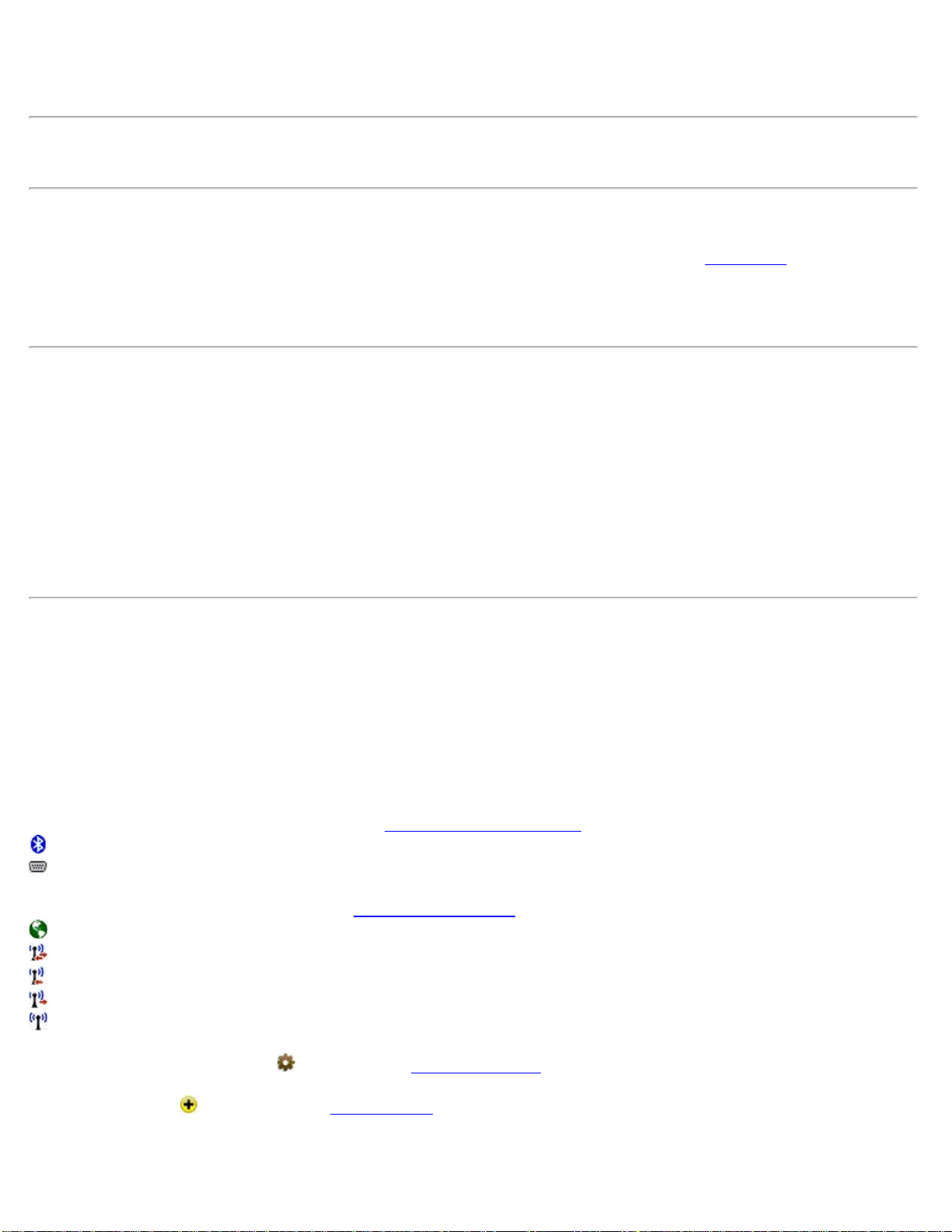
Communications Settings icon: Tap to access Receiver Communications
settings. The following icons may appear:
: The receiver is set for Bluetooth communications.
: The receiver is set for serial communications.
Data Modem Settings icon: Tap to access Data Modem Settings
. The following icons may appear:
: Internet data modem.
: Data modem that supports both base and rover operations.
: Data modem that supports only rover operations.
: Data modem that supports only base operations.
: Unknown data modem.
General Receiver Settings icon : Tap to access Receiver Settings.
Add Receiver icon : Tap to open the Add Receiver wizard.
Tap and hold the receiver profile to show the context-sensitive menu:
Survey Pro Help 5.00
24
Page 25

Receiver Info: Select to launch the Receiver Info dialog.
Rename: Select to rename the receiver profile.
Delete: Select to delete the selected receiver profile.
Receiver Communication
This dialog appears in serial mode or Bluetooth mode, depending on the icon you tap in the Add Receiver dialog.
Serial mode
In serial mode, the Receiver Comms screen includes the following:
Port: Select the COM port required to connect to your receiver from the drop-down list.
Baud Rate: Select the baud rate required to connect to your receiver from the drop-down list.
Parity: Select the parity required to connect to your receiver from the drop-down list.
[Defaults]: Tap to return all the serial port settings to their Survey Pro defaults.
[Autodetect]: Tap to automatically detect the serial port settings for your receiver.
[Change on Receiver]: Tap to change the serial port settings on your receiver. In order for this to work, you must first
have the correct serial port settings to communicate with your receiver.
Bluetooth mode
In Bluetooth mode, the Receiver Comms
screen includes the following:
Bluetooth Device: Select the Bluetooth device associated with your receiver. If your receiver is not in the list, tap
[Bluetooth Settings] to launch the Windows Bluetooth application and scan for the required Bluetooth receiver. When
you return to the Communications Settings dialog, the Bluetooth device you added to Windows is automatically
selected.
Add Receiver
[Job] [Settings] [GNSS Receivers] [Add Receiver ]
or Connect to Receiver
[Add Receiver…]
You can set up a receiver automatically or manually:
[Start Epoch Scan >]: Tap to open the Epoch Scan dialog. This automatically starts a scan that searches for all
EPOCH receivers in the area and configures them. When the scan is complete, tap [Save All] to save all the receivers
scanned and return to the GNSS Receivers tab, or the Connection prompt. Tap [Rescan] to repeat the scan.
[Start Manual Setup >]: Tap to open the Start Manual Setup
dialog. You can now set up the receiver profile manually
(see below). Use this option to configure any brand of receiver for serial or Bluetooth communication. When the scan
is complete, tap [Save] to save the setup.
For manual setup, complete the screen:
Brand: The brand of this receiver.
Model: The model of this receiver.
Bluetooth / Serial: Select the communication mode for this receiver.
If you select Bluetooth, continue as follows:
Bluetooth Device: Select the Bluetooth receiver from the Bluetooth Device list. If your receiver is not in the list, tap
Survey Pro Help 5.00
25
Page 26
[Bluetooth Settings].
[Bluetooth Settings]: Launches the Windows Bluetooth application. Enables you to create a Bluetooth profile for
your receiver.
If you select Serial, continue as follows:
Port: The data collector port used to communicate with the receiver.
Baud Rate: The baud rate used by the data collector for receiver communications.
Parity: The parity used by the data collector for receiver communication.
Note: If you do not know the receiver's settings, leave the default values. If the program fails to connect, it attempts to
auto-detect the correct settings.
Note: If a profile already exists for a receiver scanned this way, you are prompted to modify the existing profile or
discard the changes. If you choose to modify the profile, this changes the connection settings only.
[Connect]: Tap to establish a connection to the receiver and verify its capabilities. This opens the last dialog of the
Add Receiver
wizard.
The confirmation dialog shows:
Name: Receiver profile name. Default to receiver model name and last four digits of the receiver serial number but can
be overtyped.
Capabilities: The icons show that the receiver is capable of:
: RTK rover operations.
: RTK base operations.
: Post-processing operations.
[Save]: Save the new receiver.
Data Modem Settings
The Data Modem card is used to view and configure the settings for the modem used to transmit RTK base corrections
or receiver RTK rover corrections.
Modem: Select the type of modem. There will be several options here, depending on your brand and model. If the
modem you are using is not in the list of known devices, select Generic Serial to set the communication parameters to
work with just about any external data modem. The icon to the left of the modem selection list indicates the RTK
capabilities of the data modem. The following icons indicate that the data modem:
: Supports Internet modem.
: Supports both base and rover operations.
: Supports only rover operations.
: Supports only base operations.
The fields that appear on the screen change, depending on the modem you select:
Modems connected through a serial cable
Baudrate: Displays the baud rate the receiver uses to communicate with the modem.
Parity: Displays the parity the receiver uses to communicate with the modem.
Serial Port: Displays the serial port the receiver uses to communicate with the modem.
Survey Pro Help 5.00
26
Page 27

[Configure]: Opens the Modem Serial Comms. screen where you can change the settings for communication between
the receiver and the data modem.
Modems where you can set the channel and configure radio settings
Serial Port fields
Baudrate: Displays the baud rate the receiver uses to communicate with the modem.
Parity: Displays the parity the receiver uses to communicate with the modem.
Serial Port: Displays the serial port the receiver uses to communicate with the modem.
[Configure]: Opens the Modem Serial Comms.
screen where you can change the settings for communication between
the receiver and the data modem.
Radio Settings fields
Channel: Displays the last radio channel when applicable.
Sensitivity: Displays the last radio sensitivity when applicable.
[Configure]: Establishes communication with the radio firmware and opens the Radio Settings
screen where you can
change the radio channel and sensitivity settings.
Modems where you cannot configure COM settings, but can configure channel settings
Channel: Displays the last radio channel when applicable.
Sensitivity: Displays the last radio sensitivity when applicable.
[Configure]: Establishes communication with the radio firmware and opens the Radio Settings
screen where you can
change the radio channel and sensitivity settings.
Cellphone modem settings
Serial Port fields
Baudrate: Displays the baud rate the receiver uses to communicate with the cellphone.
Parity: Displays the parity the receiver uses to communicate with the cellphone.
Serial Port: Displays the serial port the receiver uses to communicate with the cellphone.
[Configure]: Opens the Modem Serial Comms.
screen where you can change the settings for communication between
the receiver and the cellphone.
Select modem fields
Select Modem: Select the specific cellphone modem that applies.
[Edit Modem]: Edit the existing modem parameters.
[Manage Modem]: Manage saved GSM modems.
Base Phone #: Enter the telephone number of the RTK base receiver’s cell phone.
Internet Protocol modem settings
Survey Pro Help 5.00
27
Page 28

Serial Port fields
Baudrate: Displays the baud rate the receiver uses to communicate with the cellphone.
Parity: Displays the parity the receiver uses to communicate with the cellphone.
Serial Port: Displays the serial port the receiver uses to communicate with the cellphone.
[Configure]: Opens the Modem Serial Comms.
screen where you can change the settings for communication between
the receiver and the cellphone.
Select modem fields
Select Modem: Select the required IP modem.
[Create Modem]: Create a new modem.
[Edit Modem]: Edit the existing modem parameters.
[Delete Modem]: Delete the existing modem parameters.
Windows networking settings
Dial-up Connection: Select the required connection from the drop-down list.
[Manage Connections]: Manage all existing connections.
[Show Advanced Settings]: Show advanced settings.
Modem Serial Comms Screen
The Modem Serial Comms. screen is used to change the settings for communication between the base or rover receiver
and the data modem.
GNSS Receiver Port: Select the serial port the receiver will use to communicate with the modem.
Baudrate: Select the baud rate the receiver will use to communicate with the modem.
Parity: Select the parity the receiver will use to communicate with the modem. This setting disabled for receivers that
do not support user defined parity setting.
[Defaults]: Automatically sets all the selectable values to their defaults based on the current receiver hardware.
[Receiver Set]: Sets the selected modem communication settings for the specified port on the receiver.
Note: The modem communication settings are also set in the receiver during the base and rover setup procedure.
Therefore, you will not usually have to use the [Receiver Set] button on this page.
Radio Settings Screen
The Radio Settings screen is used to configure settings of the base or rover radio modem. All settings available are
described below. However, not all radios support all of the described settings, so if you do not see one of these fields,
it is because the radio type does not support it.
Survey Pro Help 5.00
28
Page 29

Channel: Select the channel the radio will use to communicate with the other radio.
Sensitivity: Select the sensitivity of the radio.
Mode: Select the transmit format used by the base radio. The rover radio must be listening for same format the base is
broadcasting.
Baud: Displays the baud rate the radio is currently set to. There is no way for the software to change this value, so
you must set the receiver to radio communications to match what you see here.
Parity: Displays the parity the radio is currently set to.
[Set]: Sends commands to the radio firmware to configure the settings selected on this screen.
Note: Some settings on the radio cannot be modified with the software. To fully program the radio modems, you need
to PC software that should be supplied with the radio.
Cell Phone Settings
[Edit Modem]
or [Manage Modems ... ] [Edit]
The Cell Phone Settings
screen is used to create or modify a cell phone data modem configuration.
Auto Answer Command: Alternate Hayes AT command to use for auto answering.
Note: The default auto answer command (ATE0S0=1), default dial command (ATE0DT), and hang up command
(ATH0) are entered by default on a new configuration. See IP Modem Settings.
Number to Dial: Enter the telephone number of the RTK base receiver’s cell phone.
Hang Up: Alternate Hayes AT command to use for hanging up.
Dial Command: Alternate Hayes AT command to use for dialing.
IP Modem Settings
The IP Modem Settings screen is used to create or modify an IP modem configuration for a network server. (You can
only configure in IP modem when RTK Rover is selected for the receiver.)
Connect Command: AT modem command to connect to the base server. Default it "ATE0&D0DT".
Disconnect Command: AT modem command to disconnect from the Internet. Default is "ATH0".
General Receiver Settings
Survey Pro Help 5.00
29
Page 30

The General tab enables you to change general settings on the receiver.
Every receiver has the option to change the elevation cutoff angle and the option to set the receiver to Off Mode.
Models which have special settings available are described below.
Elevation cutoff: Keep receiver from using satellites in its position calculation that are below the given angle. The
elevation angle is given in degrees above the horizon and can be anywhere from 0 degrees (use all satellites) to 90
degrees (use no satellites).
[Set Rx. to OFF Mode]: Tap to set your receiver to Off mode. This is where your receiver does not output or accept
base corrections, effectively stopping RTK operations. This may be necessary in order to configure the radio.
Settings for Spectra Precision Receivers
If the current profile is for Promark 500/800 receiver, the general page also shows the following settings:
Storage Location: Select Internal Memory to store post processing data to the receiver's internal memory. Select USB
Memory to store post processing data a USB storage device connected to the receiver.
NMEA Outputs: Select On to enable NMEA outputs on the receiver COM port at 9600 baud, 8 data bits, and no
parity. Select Off to disable NMEA outputs.
If the current profile is for Promark 200 receiver, the general page also shows the following settings:
Storage Location: Select Internal Memory to store post processing data to the Promark device's internal memory.
Select SD Card to store post processing data a SD card in the Promark device.
NMEA Outputs: Select On to enable NMEA outputs on the Promark device's COM port. Select Off to disable
NMEA outputs.
If the current profile is for an Epoch 50 receiver, the general page also shows the following settings:
NMEA Outputs: Select On to enable NMEA outputs on receiver COM port 2 at 9600 baud, 8 data bits, and no parity.
Select Off to disable NMEA outputs.
Note: NMEA outputs are only possible when your RTK mode is NTRIP with windows networking.
Settings for Spectra Precision Receivers
If the current profile is for an Epoch 35 receiver, the general page also shows the following settings:
SBAS Tracking: Select On to enable tracking SBAS satellites. Select Off to disable tracking SBAS satellites.
Confidence Level: Select High to have the receiver ambiguity resolution use a high confidence level. This is the
desired setting for the most robust ambiguity resolution, but will result in the inability to get a fixed RTK position in
challenging GNSS environments. Select Low to have the receiver ambiguity resolution use a low confidence level.
This setting should only be used in challenging GNSS environments, and you should be aware of the possibility that
the RTK solution may fix on incorrect ambiguities.
Settings For Trimble Receivers
If the current profile is for a Trimble receiver, the general page also shows the following settings:
Log post process data to: Select handheld or receiver memory.
Survey Pro Help 5.00
30
Page 31

Glonass tracking: Select On or Off.
Settings for Thales (Ashtech) Receivers
If the current profile is for a Thales (Ashtech) receiver, the general page also shows the following settings:
Canopy: is where you set a parameter to describe the multi-path environment. This command is relevant for ROVER
mode or RVP. Choices are:
Open Sky (default)
Under Canopy (forest, urban canyon)
Confidence Level: is where you set the confidence level for ambiguity fixing. The values here are the statistical
confidence level in percent. The higher the confidence level, the more certainty that the ambiguities are fixed correctly.
But the longer it will take to fix them choices are:
99.0%
99.9%
Settings for Topcon (Javad) Receivers
If the current profile is for a Topcon (Javad) receiver, the general page also shows the following settings:
Co Op Tracking: Set the ‘common loops’ mode of the receiver. For more information on ‘common loops’ mode, see
http://www.topcongps.com/images/coop_tracking.pdf. There are two choices:
Off
On
Multi Path Reduction: Set to use C/A code phase multipath and C/A carrier phase multipath reduction. This feature
is only applicable if your receiver has the “_MRP” option enabled. There are two choices:
Off
On
Confidence Level: Set the statistical criteria to use in the RTK engine’s fixed ambiguity resolution algorithm. The
settings of ‘Low’, ‘Medium’, and ‘High’ correspond to confidence levels of %95, %99.5, and %99.9 respectively.
There are three choices:
Low
Medium
High
Note: It is recommended you set this value to High. This will usually mean the RTK engine may take longer to
resolve a fixed position. It might even mean not being able to resolve a fixed solution in some situations. However,
the consequence of a lower confidence level is that it makes it more likely to resolve an incorrect fixed ambiguity. The
results of using an incorrect fix are usually much worse than the results of using a float solution.
Antenna: Set the source for antenna input. There are two choices:
Internal
External
Survey Pro Help 5.00
31
Page 32

Note: This setting is only available when your receiver model is Hiper .
Network Settings
[Job] [Settings] [Networks Card]
To add a new network to the list, tap the add network icon
in the Networks tab.
Name: Enter a unique name for the network server.
Address: Enter the IP address for the network server.
Port: Enter the IP port for the network server.
[Save]: Tap to save the network.
To rename a network, tap the gear icon
and change the Address and Port if required.
Measure Mode Settings
[Job] [Settings] [Measure Mode]
The Measure Mode
card is used to configure the RTK data collection settings.
Accept Solution Quality: Control the solution quality acceptable for storing measurements. You have two options:
Fixed RTK only: Allows storage of fixed solution only.
Code, Float, or Fix: Allows storage of any differential solution.
Use Acceptance Criteria: Select to apply criteria to measurement acceptance. When checked, only measurements
with RMS and/or PDOP values below the threshold will be accepted. To use less than all three criteria, check this box
but enter 0.0 for the criteria you do not wish to apply.
H RMS: Horizontal RMS threshold for automatic acceptance or warning on point acceptance.
V RMS: Vertical RMS threshold for automatic acceptance or warning on point acceptance.
PDOP: PDOP threshold for automatic acceptance or warning on point acceptance.
Automatically Accept Data Collection: Select to automatically accept data collection points when the criteria is met.
When checked, both the data and Offset Shots screens will automatically accept points once the measurement is better
than the specified criteria. Data collection routines will always collect at least 5 seconds worth of data before
automatically accepting points based on criteria.
Epoch Averaging: Set a number of epochs to average in the software. If this number is greater than one, the software
will use the number of epochs specified to calculate the final position using a simple (non weighted) average.
Note: This function is not appropriate for every receiver. Some receivers, when dynamics are set to ‘static’, use
Kalman filtering and other superior techniques to calculate an average position. In this case, the position returned
from the receiver is better with each epoch and you may degrade your result by averaging with the software. You
should check with your receiver manufacturer for specific recommendations on field procedure.
Survey Pro Help 5.00
32
Page 33

Post Process Settings
[Job] [Settings] [Post Process]
The Post Process
card is used to configure the settings for logging post processing data, and the collecting and storing
of post processing points in the software.
RTK Autonomous Points: Specify action to take when accepting autonomous points during RTK data collection.
There are three options.
Do not store: Select to prohibit acceptance of autonomous points in RTK data collection routines.
Allow in PPK Survey: Select to allow storing of autonomous points when in an RTK survey that is also storing
PPK data to a post processing file.
Session Monitor: Select to use the session monitoring thresholds when collecting data with the Static / Rover Session
screen. To have the software display warnings during post processing data collection, check Warn me if, and specify
threshold values for the number of SV, HDOP and memory.
Units Settings
The Units Settings card defines the units that are used within the software, sent from the total station, entered from the
keypad and displayed on the screen. You can select the following settings for your project from the following
dropdown lists.
Units for Distances: Defines the units used for length as Meters, International Feet, or US Survey Feet.
Display Feet/Inches: Allows you to view distances in feet and inches. Available only if the current distance is
International Feet or US Feet. If selected, you can then choose the required fractions of an inch (2, 4, 8, 16, 32, 64).
Note: You can enter a distance in any distance field in units other than what is set for the job by appending the
distance value with the following characters:
f or ft or ift = International Feet
usf or usft = US Survey Feet
i or in = Inches
m = Meters
cm = Centimeters
mm = Millimeters
c or ch = Chains
Once the cursor leaves that field, the distance will be converted automatically. (A space between the value and the unit
abbreviation is optional.)
Warning: When creating a new job, it is important that the Units for Distances field be set to the correct units. This
allows you to seamlessly switch between different units in mid-job.
Problems can arise if these units are inadvertently set to the incorrect units when entering new data. For example,
assume you created a control file by hand-entering a list of coordinates in a new job where the job was set to
International Feet and the coordinates being entered were in US Survey Feet. Now assume you created another new
job and correctly set it to US Survey Feet. If you then selected the previous job as a control file for the new job, the
Survey Pro Help 5.00
33
Page 34

display of all of the coordinates in the control file would be converted from International Feet to US Survey Feet.
Units for Angles: Defines the units used for angles as Degrees or Grads (gons).
Display Directions as: Display directions as a Bearing or Azimuth.
Azimuth type: Defines if you are using a North Azimuth or a South Azimuth.
Grid Direction: specifies if your grid coordinates are increasing positive in the North East or the South West direction.
Coord. Order: Allows you to customize the labeling and order for coordinates used throughout the software. You can
select any of the following formats:
N, E, Elev. (Northing, Easting, Elevation)
X, Y, Z
E, N, Elev. (Easting, Northing Elevation)
Y, X, Z
Note: When you are doing a survey in a south west grid system, the meaning of the X/Y axes are reversed, so the
south coordinate is labeled on the X axis and the west coordinate is labeled on the Y axis .
Format Settings
The Format Settings card defines the number of places beyond the decimal point that are displayed for various values
in all screens, and how stations are defined. (All internal calculations are performed using full precision.)
Northings / Eastings: Allows you to display from zero to six places passed the decimal point for northing and easting
values.
Elevations: Allows you to display from zero to six places passed the decimal point for elevations.
Sq feet / meters: Allows you to display from zero to four places passed the decimal point for square feet or square
meter values.
Acres / Hectares: Allows you to display from zero to four places passed the decimal point for acre or hectare values.
Distances: Allows you to display from zero to six places passed the decimal point for distances.
Angles: Allows you to include from zero to two fractional seconds with angle values.
Stations: Allows you to display stations in any of the following formats:
12+34.123: Displays stations where the number to the left of the + advances after traveling 100 feet or meters.
1+234.123: Displays stations where the number to the left of the + advances after traveling 1,000 feet or meters.
1,234.123: Displays standard distances rather than stations.
Files Settings
The Files Settings card allows you to select a feature code definition file.
Survey Pro Help 5.00
34
Page 35

Feature Code File: Displays the selected feature code file (*.FXL) to use with the current job. FXL files can be
created and customized with the Spectra Precision Feature Definition Manager.
[Browse]: Opens a dialog to select a feature code file to use with the current job. Tap the filename and then tap
[Open].
[Clear]: Closes the currently selected file so that it is no longer used with the current job.
Descriptions Settings
[Job] [Settings] [Descriptions]
or
(from any Description field), Description Settings…
The Descriptions Settings
card allows you to select description code files and configure how descriptions are handled.
Use Description Code File: Mark this item to use a description file that contains codes and click the associated
[Browse] button to navigate to and select the file.
Description code files contain one code/description pair per line where the code and description are separated by a
space or a tab. (The code cannot contain spaces.)
Use Description List File: Mark this item to use a description file containing a list of descriptions without codes –
one description per line and click the associated [Browse] button to navigate to and select the file.
Load Description List from Job File: Marking this item results in descriptions used in the current job, as well as any
new descriptions entered, to be included in the description list. Add New Descriptions to Description List: Marking
this item results in only new descriptions entered since marking this box to be included in the description list. (If the
preceding box is marked, new descriptions are added whether or not this item is marked.)
Show Description List Automatically: Marking this item results in a drop-down list of descriptions being displayed
as soon as text is entered into a Description: If unmarked, the list can be displayed by selecting Show Description
List using the
power button associated with a Description field. Double-clicking a description in the list will
replace the entered text with the selected description.
Surveying Settings
The Surveying Settings card allows you to select various options that affect how data collection is performed.
Prompt for PPM during Station Setup: When checked, you will be prompted to enter the PPM correction factor as
part of your conventional station setup.
Prompt for Description: When checked, a prompt for a description will appear before any new point is stored from
only the routines under the Survey
menu.
Note: Descriptions can be no longer than 256 characters.
Prompt for Height of Rod: When checked, a prompt for the rod height will appear before any new point is stored.
Prompt for Layer: When checked, a prompt to select a layer will appear before any new point is stored from only the
Survey Pro Help 5.00
35
Page 36

routines under the Survey menu.
Prompt for Attributes: When checked, a prompt to select feature information will appear before any new point is
stored from only the routines under the Survey
menu. This also requires that a feature file be selected from the Files
Settings card.
Prompt for Picture: When checked, a prompt will appear before storing a point where you have the option of taking
one or more pictures associated with the current point. (Only available when running on a Nomad or a Ranger 3 with a
digital camera.)
Survey Map Use Enter Button for Topo: When checked, the enter key on the active survey map will take a topo
shot. When unchecked, the enter button on the active survey map will take a normal shot.
Detect Duplicate Shots: When checked, a prompt will appear before attempting to store a second shot to the same
location. This helps to catch when robotic total stations have lost lock while surveying. The distance tolerances set in
the Repetition Settings
screen are used in determining when two shots are at the same location.
Survey with True Azimuths: Automates the process of adjusting the circle on the total station when traversing so that
you can survey with azimuths rather than horizontal angles.
Skip Check during Station Setup: Select this checkbox to skip the check during the station setup procedure.
Earth Curvature & Refraction: Allows you to select the earth curvature and refraction correction coefficient. Select
None to turn Earth Curvature & Refraction correction off.
Scale Factor Settings
The Scale Factor card shows you the current scale factor mode for scaling ground to grid distances.
[ Setup Scale …]: opens up the Scale Settings
screen where you can select the desired method to use for scaling
ground to grid distances.
Note: Scaling of ground to grid distances is usually only required when your coordinate system is set to some kind of
conformal mapping plane. For a simple plane survey using a flat earth model, where ground measured distances are
1:1 to coordinate grid distances, you should leave your scale factor turned off.
Scale Settings
[Job] [Settings] [Scale Factor] [Setup Scale]
The Scale Settings
screen is the starting point for setting up a mapping grid scale factor. Once configured, you will
return to the Surveying Settings screen where you must then tap to save the scale settings.
Do not use a scale factor: Disable any mapping plane scaling that is currently enabled.
Use a single combined scale factor: Uses a single combined scale factor that is provided for you, or one can be
computed with the Calculate Scale
wizard.
Use a grid factor with sea level correction: Uses a mapping plane scale factor that is adjusted for elevation changes.
Use automatic map plane grid factor with sea level correction: Uses a combined scale factor that is adjusted for
Survey Pro Help 5.00
36
Page 37

elevation changes.
Use map plane ground coordinates: When selected, you can configure the job to use map plane ground coordinates.
Combined Factor: Enter a combined scale factor if already known, otherwise is the combined scale factor computed
from the Calculate Scale
wizard.
Grid Factor: Enter a map plane scale factor if already known, otherwise is the scale factor computed from the
Calculate Scale wizard.
[Calculate Scale]: Opens the Calculate Scale
wizard, which is used to calculate a combined scale factor or map plane
scale factor.
[Setup Map Ground Coordinates]: First checks that a map projection is selected and if not, prompt you to select one.
Next, opens a wizard where after providing an origin point and ground system offset coordinates, the entire job
northing/easting database will be updated with the ground coordinate system transformation.
[Change Map Zone]: Opens the Select Coordinate System
wizard where you can choose a mapping plane zone or
calibrated site from the coordinate system database file. You can also create a new zone and datum with user-specified
parameters.
Calculate Scale
[Job] [Settings] [Scale Factor] [Setup Scale] [Calculate Scale]
The Calculate Scale
wizard is available when Use a single combined scale factor or Use a grid factor with sea level
correction is selected in the Scale Settings
screen and is used to compute a scale factor. If a map zone is not currently
selected, you will first be required to set one up
before continuing.
Projection: Displays the details about the current map zone.
Select Point: Specify a reference point.
[Calc Scale >]: Opens Screen Two if Use a single combined scale factor was selected. If Use a grid factor with sea
level correction was selected, you will return to the Scale Settings
screen and the computed grid factor will be entered
for you.
- Screen Two Ellipsoid Height: The height of the ground above the ellipsoid surface.
[< Back]: Returns to the previous screen.
[Solve >]: Opens Screen Three.
- Screen Three Mapping Plane Scale Factor: Displays the scale factor that will correct for the effects of map projection distortion.
Ellipsoid Scale Factor: Displays the scale factor to correct for the geometric effect of your height above the ellipsoid
surface.
Ground to Grid: Displays the combined scale factor that will be used for ground to grid calculations. Grid to Ground:
displays the inverse of the combined scale factor for grid to ground calculations.
Survey Pro Help 5.00
37
Page 38

[< Back]: Returns to the previous screen.
[Solve >]: Returns to the Scale Settings
screen where the combined scale factor will be entered for you.
Stakeout Settings
The Stakeout Settings card contains the setting that control how stakeout is performed. (The settings available depend
on if you are running in conventional or GNSS mode.)
Stake “Corners,” Not Just Even Intervals: When staking by stations, locations where a line segment changes, such
as from a straight section to a curve, will also be staked when this is checked.
Stake Bisector of Non-tangent Corners: When staking an offset to a centerline that contains a corner, this option,
when checked, will stake the corner point where the two offsets intersect.
Always Start Stakeout With Coarse Mode: When checked, the EDM mode toggle button found in all stakeout
screens will initially be set to coarse mode (fast shot). This instructs the total station to measure distances faster, but
with slightly less accuracy.
Use Manual Updating (Remote Control): When checked, a [Shot] button in the stakeout screens must be tapped to
take a shot. When this not checked, shots are continuously taken in the stakeout screens. (This is only valid when
running in remote mode, using a robotic total station.)
Design Elevation from Offset Segment: Determines where the cut/fill value is computed from in the Offset
and Road
Stakeout screens when the Offset checkbox is checked and a non-zero offset is entered. When checked, the cut/fill
value is calculated from the design elevation of the node you are staking to. When unchecked, the cut/fill value is
calculated from the design elevation at the specified offset location.
Note: If the specified offset extends beyond the end of the road profile, the cut/fill value is always computed from the
design elevation of the node you are staking to.
View from Instrument to Rod (non-remote): When checked, the move left or right information will be presented
from the rod person’s point of view. When unchecked it will be presented from the total station’s point of view. (This
option only applies when a robotic total station is selected in the Instrument Settings
.)
View from Rod to Instrument (remote): When checked, the move left or right information will be presented from
the rod person’s point of view. When unchecked it will be presented from the total station’s point of view. (This
option only applies when a non-robot total station is selected in the Instrument Settings
.)
Prompt for Layer: When checked, a prompt to select a layer will appear before any new point is stored from the
routines under the Stakeout
menu.
Prompt for Attributes: When checked, a prompt to select feature information will appear before any new point is
stored from only the routines under the Stakeout
menu. This also requires that a feature file be selected from the Files
Settings card, described earlier.
Note: There is no Prompt for Description checkbox as in the Surveying Settings
card because you are always prompted
for a description when storing a point from a stakeout routine.
Prompt for Picture: When checked, a prompt will appear before storing a point where you have the option of taking
Survey Pro Help 5.00
38
Page 39

one or more pictures associated with the current point. (Only available when running on a Nomad or Ranger 3 that has
a digital camera.)
Use Perfect Stationing: When checked, staking locations will be computed at perfect stationing intervals. For
example, if your starting station was 0+15 and your station interval was 100, your next stakeout location will occur at
1+00 instead of 1+15.
Use Design Point Description as Descriptor: When checked, the descriptor for a staked point that is stored will
automatically be set to the same descriptor used for the design point. When unchecked, the descriptor for a stored stake
point will automatically be set to the point number of the design point that you are staking.
Point Tolerance: Affects the Remote Staking
routine. When performing Remote Stakeout, the final graphic screen that
is displayed when you are near the stake point will occur when you are within the distance to the stake point specified
here.
Line Tolerance: Affects the Stake to Line
routine. When staking to a line and the prism is located at a perpendicular
distance to the specified line that is within the range set here, a message will state that you are on the line.
Horizontal Distance Tolerance: Affects the GNSS staking routines. When you are within the specified distance to the
location you are staking, you are considered on that location.
Turn instrument to design point: Applies only to motorized total stations. The following options are available:
2D (HA only): A motorized total station will turn horizontally toward the design point after tapping the Turn
Instrument button in the particular stakeout screen.
3D (HA and ZA): A motorized total station will turn horizontally and vertically toward the design point after
tapping the Turn Instrument button in the particular stakeout screen.
Automatic 2D (HA only): A motorized total station will automatically turn horizontally toward the design point
when the stakeout screen opens.
Automatic 3D (HA and ZA): A motorized total station will automatically turn horizontally and vertically toward
the design point when the stakeout screen opens.
Cut Sheet Offset stored: The cut sheet offset information can be stored to the raw data file in either of the following
formats when performing any offset staking routine:
Design Offset: When selected, a cut sheet report will list the design-offset values.
Actual Offset: When selected, a cut sheet report will list the measured-offset values.
Display Directions As: Guides you to the GNSS stakeout location using one of the following formats:
Northing / Easting: Suggests you Go South/Go North and Go West/Go East.
Distance / Azimuth: Displays the necessary Azimuth and Distance to the stakeout location.
Forward / Back: Suggests you go FORWD/BACK and Go Left/Go Right when you are within 3 meters to the
location. When you are farther than 3 meters, a distance and azimuth is used.
Repetition Settings
The Repetition Settings card contains the settings that control how repetition shots are performed and acceptable
tolerances.
Horizontal Tolerance: A warning message will be displayed if a horizontal angle exceeds the tolerance entered here
during a repetition shot.
Survey Pro Help 5.00
39
Page 40

Zenith Tolerance: A warning message will be displayed if a vertical angle exceeds the tolerance entered here during a
repetition shot.
Distance Tolerance: A warning message will be displayed if a distance exceeds the tolerance entered here during a
repetition shot.
Shoot Distance To Backsight: When checked, a distance will be measured to each shot to the backsight. When
unchecked, only the angles are measured.
Do Not Shoot Reverse Distances: When checked, distances are not measured during reverse shots.
Enable Automatic Repetition: When checked, all remaining shots after the first shot to the backsight and foresight
will occur automatically when using a motorized instrument.
Shooting Sequence: Specifies the order that the shots are taken from the following options:
BS > FS ^ FS > BS: Backsight, Foresight, flop Foresight Backsight
BS > FS ^> BS > FS: Backsight, Foresight, flop Backsight, Foresight
BS ^ BS > FS ^ FS: Backsight, flop Backsight, Foresight, flop Foresight
FS ^ FS > BS ^ BS: Foresight, flop Foresight, Backsight, flop Backsight
FS > BS ^ BS > FS: Foresight, Backsight, flop Backsight, Foresight
FS > BS ^> FS > BS: Foresight, Backsight, flop Foresight, Backsight
BS ^ BS ^ > FS ^ FS ^: Backsight, flop, Backsight, flop, Foresight, flop, Foresight, flop
Date/Time Settings
The Date/Time Settings card is used to set the date and time in the data collector.
Time: Displays the current time.
Date: Displays the current date.
Format: Select Local to display your local time, or UTC to display Coordinated Universal Time.
DUT Correction: The polar wandering correction factor, in seconds, used to convert UTC to
UT1. (UT1=UTC+DUT)
Note: The date, time and UTC are computed using Window CE's Date/Time properties.
[Set Date]: Sets the system date with the date that is entered.
[Set Time]: Sets the system time with the time entered.
[Synchronize]: Zeros the fractional portion of the current time and advance to the nearest second so that the time can
be set more accurately.
NMEA GPS Settings
The NMEA GPS card is used to configure the settings for a NMEA GPS receiver for use with the GeoLock and
Navigation
routines.
Survey Pro Help 5.00
40
Page 41

Turn On NMEA GPS Receiver: When checked, enables the GPS receiver.
Model: Select Shared GPS to use the GPS receiver settings configured in the Windows operating system (see [Shared
GPS…] below) or select Generic NMEA and configure the settings from this screen.
Serial Port: The serial port on the data collector used to communicate with the GPS receiver.
Device (available only when using a Bluetooth GPS receiver and Bluetooth is selected for the Serial Port): Select the
Bluetooth device that represents your GPS receiver here.
[Bluetooth…] (available only when using a Bluetooth GPS receiver and Bluetooth is selected for the Serial Port):
Accesses the Bluetooth configuration screen where you can quickly check or change Bluetooth settings. See the User’s
Manual for more information on configuring Bluetooth.
Baud Rate: The speed that communication takes place. This must match the baud rate set in the GPS receiver.
Parity: This must match the parity set in the GPS receiver – usually None.
[Shared GPS…]: Shortcut to the
> Settings > GPS screen. You can get more information while viewing this
screen by tapping
then .
Data Out settings
The Data Out Settings card is used to configure settings for exporting data to a serial port or file.
Enable Data Out: When selected, enables export of external data output to a serial port or to a file.
To Serial Port: Select to export data to the serial port on the data collector. You must enter the Serial Port, Baud Rate,
and Parity. If you select Bluetooth as the serial port, you can check or change the Bluetooth settings.
To File: Select to export data to a file. You must enter the output file name.
Send Point Coordinates: Select to export point coordinates. For conventional surveys, the plane (N, E, Elev)
coordinates for each stored point are exported. For GNSS surveys, the plane (N, E, Elev) and geodetic (Lat, Lng, Ht)
coordinates for each stored point are exported.
Send Observations: Select to export setup and observation records. This will enable you to calculate solved
coordinates from raw observations.
Serial Port: (available when the output method is ‘To Serial Port’) Select the serial port on the data collector for the
external data output. This cannot be the same port as the current active instrument (conventional or GNSS).
Baud Rate: The baud rate for the external data output port.
Parity: The parity of the external data output port.
[Bluetooth]: (available when the port for external data output is set to Bluetooth) Opens the Bluetooth configuration
screen where you can quickly check or change Bluetooth settings. See the User Manual for more information on
configuring Bluetooth technology.
Path: (available when the output method is ‘To File’) Shows the location of the saved file. To select a different path,
click [Browse].
Survey Pro Help 5.00
41
Page 42

File: (available when the output method is ‘To File’) Enter the file name for saving the external data output. To select
a different file type, click [Browse].
[Browse]: (available when the output method is ‘To File’) Click to open a file browse dialog where you can select the
file name and path for the output file. The default file extension is .XML, but you can use any extension.
Buttons Settings
The Buttons Settings card is used to customize the function for the physical buttons located on the data collector.
The upper half of the screen lists all of the customizable button’s current assignments. A particular button must be
selected from this list prior to changing its settings from the lower half of the screen.
Assignment Within Survey Program: Select the function for the selected button when it is used within the software.
The function of the button will switch back to its global assignment when it is used outside the software. Selecting
<Global> from this field will result in the global assignment also being used from within the software.
Global Assignment: Select the function for the selected button when it is used outside the software.
[Survey Defaults]: Set all assignments in the Assignment Within Survey Program field to the software's default
settings.
[System Defaults]: Set all assignments in the Global Assignment field to the system default settings and set all the
assignments in the Assignment Within Survey Program field to <Global>.
General Settings
The General Settings card contains the following miscellaneous settings:
Auto time stamp every: When checked, a note will be entered into the .survey file consisting of the current time each
time the number of minutes specified passes. This can help track when specific events occurred.
Remind to backup job every: When checked, a prompt will occur each time the specified number of hours passes
reminding you to backup your job.
Use Enter Key to Move Between Fields: When checked, the [Enter] key will move the cursor to the next field in all
screens. When unchecked, the [Enter] key will perform a different function depending on the field selected.
Note: The arrow keys can also be used to move the cursor between fields.
Allow Alphanumeric Point Names: When checked, numeric or alpha character can be used for point names. If
unchecked, only numeric point names are valid.
Beep When Storing Points: When checked, a beep will sound whenever a new point is stored.
Beep On Control Activation: When checked, a beep occurs when any button, checkbox, or other control is tapped.
Prompt for Description: When checked, a prompt for a description will appear before any new point is stored from
any routine other than those included in the Survey
and Stakeout menus.
Survey Pro Help 5.00
42
Page 43

Prompt for Layer: When checked, a prompt to select a layer will appear before any new point is stored from any
routine other than those included in the Survey and Stakeout menus.
Prompt for Attributes: When checked, a prompt to select feature information will appear before any new point is
stored from any routine other than those included in the Survey and Stakeout menus. This also requires that a feature
file be selected from the Files Settings
card, described earlier.
Prompt for Picture: When checked, a prompt will appear before storing a point where you have the option of taking
one or more pictures associated with the current point. (Only available when running on a Nomad or a Ranger 3 with a
digital camera.)
Prompt to Backup When Closing Job: When checked, you will be reminded to backup the current job prior to
closing it.
Prompt for Elevation of 2D Cogo Points: When checked, a majority of the COGO routines will prompt you for an
elevation before storing a 2D point. When unchecked, 2D points will be stored without the prompt.
Always Use ALL CAPS in Edit Fields: When checked, characters will always be entered using capital letters in edit
fields, regardless of the keyboard setting.
Log Serial Port Traffic: When checked, all serial port traffic will be logged to a text file called TDS-Log.txt for
troubleshooting purposes and is stored in the Jobs folder. The file is automatically overwritten when logging traffic on
a date that is different from the previous date.
Use Smart Soft Input Panel Activation: When checked, the SIP will automatically open when the cursor is inside an
input field and close when the cursor is moved outside an input field. (Not available on Ranger data collectors.)
Edit Points
[Job] [Edit Points]
The Edit Points
screen allows you to add, edit, and delete any points in the current job.
[Edit…]: If only a single point is selected, this will open the point in the Edit Point Screen
where the details of the
point can be modified. If more than one point is selected, the Edit Points Screen
will open where the description, layer,
and elevation for the selected points can be modified simultaneously.
Note: Multiple points can be selected by tapping the first point in a range, then tap the shift key from a soft input
panel, and lastly tap the last point in the point range. Individual points in a point range can be selected/unselected by
tapping the control key from a soft input panel and then tapping the desired points.
Note: Double tapping on a point will open that point in the editor.
[Insert…]: Opens a screen where a new point can be added.
[Delete…]: Delete the selected point.
[Find…]: Search for a point by its description.
[Find Next]: Find the next point that contains the description entered when using the [Find…] button.
[Go To…]: Opens a dialog box where any point can be quickly located by the entered point name.
Survey Pro Help 5.00
43
Page 44
Edit Points - (multiple point editing)
[Job] [Edit Points] [Edit…]
(When more than one point is selected.)
This screen is accessed after tapping [Edit…] when more than one point is selected. The change made in this screen
will be applied to all the selected points.
Description: When checked, allows you to change all the selected point's descriptions to the Description entered in the
description edit field.
Layer: When checked, allows you to move the selected points to the layer selected in the layer edit control.
Note: Only user entered points (key in or imported) can be placed on the Control layer. If any of the points in the
selection are derived from measurements, then the control layer will not be an option in the layer edit box.
Elevation: When checked, allows you to move the selected points to the elevation entered into the elevation edit field.
Note: You can only change the elevation of multiple points if all of the points in the selection are derived from user
input (key in or imported). If any of the points in the selection are derived from observations, the Location
card will
not be displayed.
Edit Point
[Job] [Edit Points] [Edit…]
The Edit Point
screen is used to modify point properties.
There are three cards on the Edit Point
screen:
General Edit Point - General Card
Location Edit Point - Location Card
Feature Edit Point - Feature Card
Edit Point - General
[Job] [Edit Points] [Edit…] [General]
The General
card of the Edit Point screen is used to modify the description, layer and picture information for the
selected point.
Point Name: Displays the selected point's name.
Description: The description for the selected point.
Layer: The layer for the selected point.
Survey Pro Help 5.00
44
Page 45

Note:; Only user entered points (key in or imported) can be assigned as control points. If the point selected for editing
is derived from a measurement, then you will not see the Control layer in the layer edit box.
Picture: Displays a list of pictures associated with a point. You can click the drop-down list to see the pictures
associated with the job. Use the Power button to view or delete any of the pictures associated with a point. Use the
camera button to open the camera application and take additional pictures for a point.
Note: When you delete a picture using the menu item, the picture is disassociated from this point in the job, but the
picture file is not removed from the disk. To get rid of the actual picture file, you must use the file explorer to delete
the file.
Note: The camera button is only available on a Nomad or Ranger 3 data collector that has an integrated digital
camera.
Edit Point - Location
[Job] [Edit Points] [Edit…] [Location]
The Location
card is used to modify the coordinate of a user entered point, or to show the point detail information for
any point derived from a survey measurement.
If the selected point was entered by the user (or imported from an external file), you can edit the coordinate values:
Coordinate Type is used to select what kind of coordinate is entered for this point:
Grid enter a northing, easting, elevation coordinate for this point.
WGS84 LLH enter a latitude, longitude, height coordinate in the global geodetic datum for this point.
Local LLH enter a latitude, longitude, height coordinate in the local datum for this point.
If the point was derived from a survey measurement, then this card shows point details for the selected point
[GNSS Control Point]: Opens up the GNSS Control Point Pair Screen
.
GNSS Control Point Pair
[Job] [Edit Points] [Edit…] [Location] [GNSS Control Point]
The GNSS Control Point Pair
screen is used to associate a pair of points together to form a GNSS control point. One
of the points must be a local grid point, and one point must be a GNSS point.
[Use as Calibration Control Point]: check this box if you wish to use the selected point as a GNSS calibration
control point.
[GNSS Point / Grid Point]: choose a point to pair with the selected point to form a calibration point pair.
[Use for Horizontal Calibration]: check this box if the calibration point pair is suitable to use for horizontal
calibration.
Survey Pro Help 5.00
45
Page 46

[Use for Vertical Calibration]: check this box if the calibration point pair is suitable to use for vertical calibration.
Edit Point - Feature
[Job] [Edit Points] [Edit…] [Feature]
The Feature
card is used to modify the feature code and line work control code associated with the point.
Any feature codes for the selected point are shown in the list of codes. Each line of the list of codes shows:
Code Icon: Icon for the code. If you are using a FXL feature file, this icon will show whether the code is for a
point feature or a line feature. If you are not using a FXL feature file, or if this code is not defined in the FXL
file, the icon will be blank showing that it is a user entered feature.
Code Name: The abbreviated code string for this code.
Line work Icon: An icon representing the state of the auto line work for the point with this code.
Attribute: If this code also has feature attributes defined for it, the attribute icon will show if the attributes have
been entered.
Delete: Tap the x to remove this code from the point.
[+]: opens up the Pick a Feature Screen
where you can key in any code you wish or select one from a list of codes
defined in the Feature File (.FXL).
Pick a Feature
The Pick a Feature screen is used to enter a feature code string. You can pick a feature code from the list of codes, or
you can enter the string directly into the edit field. If you are using a Feature Code File (.FXL), you can pick from the
list of codes defined in the file, or you can enter any other code string to define a new feature. If you are not using a
Feature Code File, you can simply enter any string you wish to define the feature code for a point.
Filtered By: shows the current selection filter. You can tap on the filter icon to change the view filter.
[Feature Code]: enter the text string for a code, or double tap on the list to select the code string for an existing code.
Note: You can enter a code and the line work control code separated by a space in the [Feature Code] edit field, or
you can enter just the feature code and then assign the line work code with by tapping the line work icon next for that
feature code in the list of codes for this point.
Edit Polylines
[Job] [Edit Polylines]
The Edit Polylines
screen is used to add, edit, and delete polylines in the current job.
The first screen will display a list of all the polylines that are stored in the current job. Selecting any of the polylines
listed will display a horizontal (overhead) and vertical (side) view of that polyline.
[Edit…]: Open the selected polyline in the New Polyline
screen, described below.
Survey Pro Help 5.00
46
Page 47

[Delete…]: Delete the selected polyline.
[New…]: Open the Polyline Editor where a new polyline can be created.
Import PL5: Import polylines. Available on the Power menu button item. Tap the down arrow to open this menu from
the Edit Polylines screen.
Export PL5: Export polylines. Available on the Power menu button item. Tap the down arrow to open this menu from
the Edit Polylines screen.
New Polyline
The second screen is used to define all of the points that are used in the polyline. Any curve information will be
entered later, but the end points must still be selected at this point.
The current polyline is shown on color displays with bold red lines and all other polylines are shown using thin black
lines. Only the current polyline data can be edited.
[Tap Points…]: Opens a map view where the points in your polyline can be tapped. They must be tapped in the order
that they occur in the polyline.
[To/From…]: Allows you to define a range of points to define a polyline.
[Edit…]: Opens the third screen, described next, where the current polyline can be modified.
[Clear]: Removes the current polyline.
[Properties]: Allows you to enter a Description and select a Layer for the Polyline. If you have a feature code
loaded, you can also add [Attributes].
Polyline Editor
Once the initial points are selected for the current polyline, the third screen allows you to modify the polyline and
define any curve and grade information for the polyline sections.
Selecting any point in the left column of the screen will select that point and the line segment that follows it up to the
next point. The selected section is then highlighted in the map portion of the screen. Any edits will occur on the
selected section.
[Remove]: Remove the selected point and the line segment that follows it. The previous line segment will be
automatically joined to the following point. The change will only be saved if you then tap
. Tapping will return to
the previous screen without saving the changes.
[Clear All]: Completely removes the current polyline. The change will only be saved if you then tap
. Tapping
will return to the previous screen without saving the changes.
[Curves…]: Opens the fourth screen, described below, where a horizontal, vertical, or spiral curve can be added to the
selected polyline segment.
Horizontal / Vertical: Toggles between showing the map in a Horizontal (overhead) view or a Vertical (side) view.
[<- Insert]: Insert a point, or a group of points in front of the selected point. The change will only be saved if you then
Survey Pro Help 5.00
47
Page 48

tap . Tapping will return to the previous screen without saving the changes.
Note: if <End> is selected in the list, the [<-Insert] button will change to an [<-Append] button to indicate that
additional points will be appended to the end of the list.
Add/Edit Curve
The fourth screen is used to modify a selected polyline segment that occurs between two points. A horizontal, vertical,
and/or spiral curve can be applied to the polyline segment.
Adding a Horizontal Curve Tap the [Arc / Spiral] tab.
Curve: Set to Arc to enter a horizontal curve.
[Radius] | [Delta] | [Degree Arc] | [Degree Chord]: Allows you to specify the radius of the curve using a variety of
methods.
[Turn]: Specifies if the curve turns toward the Right or Left as you occupy the initial point and face the end point.
[Arc]: Specifies if the arc of the curve is Small (less than 180°) or Large (greater than 180°).
Adding a Spiral: Tap the [Arc / Spiral] tab.
Curve: Set to Spiral to enter a spiral curve.
Radius: The radius of the spiral curve. (The same radius of the circular curve adjacent to the spiral.)
Length: The length of the spiral, measured along the curve from the TS to the SC.
Turn: Specifies if the spiral curve turns to the Right or Left as you occupy the initial point and face the end point.
Direction: Specifies if the curve runs from where the tangent intersects with the spiral toward where the spiral
intersects with the curve (TS->SC) or if the curve runs from where the curve intersects with the spiral toward where
the spiral intersects with the tangent (CS->ST).
Adding a Vertical Curve: Tap the [Parabolic Curve] tab.
Apply Curve: Checked to enter a vertical at curve.
Grade at EVC / BVC is the known grade at either the end of vertical curve or beginning of vertical curve. The grade
entered here is determined by the selection made in the Auto-Compute field.
Auto-Compute: Automatically compute the grade at the selected point and display it on the screen. The grade at the
point that is not checked here must be specified in the field defined above.
Edit Alignments
The Edit Alignments screen is used to create and edit alignments, which can then be used with routines such as Offset
Staking, Offset Points, Offset Lines and Road Layout.
Alignments are used to describe all of the horizontal and vertical details of a road's centerline. An alignment does not
Survey Pro Help 5.00
48
Page 49

use existing points to define any particular locations on the alignment, although a point can be used to anchor the
starting location, which is the same location for both the horizontal and vertical parts of the alignment. Any location on
an alignment where a change occurs is called a node.
An alignment can contain straight sections, grades, horizontal, vertical, and spiral curves. The horizontal and vertical
portions of an alignment are defined separately and independently, but they are both combined within the software to
create a single alignment with horizontal and vertical characteristics.
Add / Edit Alignments
[Job] [Edit Alignments] or [Roads] [Edit Alignments]
The Add / Edit Alignments
screen displays a list of all the existing alignments in the current job. The right portion of
the screen shows a graphic of the horizontal and vertical portion of the selected alignment.
[New…]: Opens the Edit Alignment screen where a new alignment can be created from scratch.
[Edit…]: Opens the Edit Alignment
screen where the details of the selected alignment can be edited.
[Delete…]: Used to delete the selected alignment.
: The power button opens the following routines:
Create Points: Opens the Create Points screen where points can be stored that coincide with the selected
alignment.
Import .RD5 File: Opens the Open screen and lists all the *.RD5 alignment files in the Jobs directory. Select
the desired file and tap .
Export .RD5 File: Opens the Save As screen where the current alignment can be saved to a *.RD5 file.
Edit Alignment
[Job] [Edit Alignments] [Edit…]
or [Job] [Edit Alignments] [New…]
The Edit Alignment screen is used to edit an existing alignment or create a new one.
Edit Alignment Screen – HAL Tab
The HAL (Horizontal ALignment) tab in the Edit Alignment screen is used to enter or modify only the horizontal
details of an alignment.
[Insert…]: Opens the Edit Segment
screen where a new horizontal alignment segment can be inserted prior to the
selected segment.
[Edit…]: Opens the Edit Segment screen where the selected horizontal segment can be modified.
[Remove]: Removes the selected segment and automatically joins the next segment with the previous segment.
Note: The station and azimuth at the beginning of the selected horizontal segment are displayed at the bottom of the
screen.
Survey Pro Help 5.00
49
Page 50

Edit Alignment Screen – VAL Tab
The VAL (Vertical ALignment) tab in the Edit Alignment
screen is used to enter or modify only the vertical details of
an alignment.
Note: The total horizontal length of the VAL must be equal to or greater than the total horizontal length of the HAL
when the alignment is used for road layout.
[Insert…]: Opens the Edit Segment
screen where a new vertical segment can be inserted prior to the selected segment.
[Edit…]: Opens the Edit Segment
screen where the selected vertical segment can be modified.
[Remove]: Removes the selected segment and automatically joins the next segment with the previous segment.
Note: The station and elevation at the beginning of the selected vertical segment are displayed at the bottom of the
screen.
Edit Alignment Screen – POB Tab
The POB (Point Of Beginning) tab in the Edit Alignment
screen is used to define the starting location of the
alignment. The first horizontal and vertical segment will always begin at this location.
[Location]: Starting location for the horizontal and vertical alignments will be at the specified North, East and Elev
coordinates.
[Point]: Starting location for the horizontal and vertical alignments will be at the specified Point.
Start Station: The station on the alignment that corresponds with the starting location or point.
Edit Alignment Screen – General Tab
The General tab in the Edit Alignment
screen is used to describe the alignment and select the layer where it is located.
Description: The description of the alignment.
Layer: The layer where the alignment will be located.
[Attributes]: Opens the Point Feature Attributes
screen where the feature attributes for the alignment can be selected.
Edit Segment
The Edit Segment screen is accessed anytime an existing horizontal or vertical segment is added or edited. A variety of
segment editing screens are possible depending on the type of segment being edited or created. Each segment editor is
discussed below.
Edit Segment - Line Card
The Line card is used to add a straight horizontal line segment in the alignment.
Survey Pro Help 5.00
50
Page 51

Length: The horizontal length of the line.
Make this segment tangent to previous: When checked, the specified line will be tangent to the ending tangent of the
previous segment.
Note: When making a new horizontal segment tangent to the previous segment, the new segment will appear in the
Edit Alignment screen tagged with a (P). This means that if the previous horizontal segment is edited or deleted, where
the orientation changes, all subsequent horizontal segments that have the (P) tag will also be adjusted so they will
remain tangent to the previous segments. This does not hold true for vertical alignment segments. Vertical segments
will always begin with the specified starting grade unless they are manually modified.
[Azimuth] / [Bearing]: Used to enter a known azimuth or bearing of the line.
: Adds the line to the current horizontal alignment.
Edit Segment - Arc (Horizontal Curve) Card
The Arc card is used to add a horizontal curve to the alignment.
The curve can be defined by two of the following:
[Radius]: The distance from the radius point to the curve
[Delta]: The internal angle from center to tangent points.
[Degree Arc]: The internal angle equivalent to a 100-ft arc length.
[Degree Chord]: The internal angle equivalent to a 100-ft chord length.
[Length]: The arc length.
[Chord]: The chord length.
[Tangent]: The distance from the PC or PT to the PI.
[Mid Ord]: The distance between the curve and the chord at the center of the curve's length.
[External]: The minimum distance between the PI and the curve.
Turn: Specifies if the curve turns to the Left or Right as you face the curve from the beginning.
Make this segment tangent to previous: When checked, the start of the specified curve will be tangent to the ending
tangent of the previous segment.
[Azimuth] / [Bearing]: Used to enter a known azimuth or bearing at the start of the curve.
: Adds the curve to the current horizontal alignment.
Edit Segment - Spiral Card
The Spiral card is used to add a spiral curve to the alignment.
Radius: The radius of the spiral. (This equals the radius of the horizontal curve tangent to the spiral.)
Length: The length of the spiral.
Turn: Specifies if the curve turns to the
Left or Right as you face the curve from the beginning.
Survey Pro Help 5.00
51
Page 52

Dir: Specifies if the curve runs from TS to SC (Tangent to Spiral, to Spiral to Curve) or CS to ST (Curve to Spiral, to
Spiral to Tangent).
Make this segment tangent to previous: When checked, will automatically turn the spiral so the beginning is tangent
to the end of the previous segment.
[Azimuth] / [Bearing]: Used to specify a known azimuth or bearing of the start of the spiral.
Edit Segment - Vertical Grade Card
The Vertical Grade card is used to enter a segment with any grade.
Length: The horizontal length of the segment.
Grade: The grade (slope) of the segment.
Get Previous Grade: Automatically enter a grade equal to the grade at the end of the previous segment.
Edit Segment - Vertical Curve
The Vertical Curve card is used to enter a parabolic vertical curve to the alignment. Length: is the horizontal length of
the vertical curve.
Start Grade: The starting grade of the vertical curve.
End Grade: The ending grade of the vertical curve.
[Get Previous Grade]: Automatically enter a Start Grade equal to the grade at the end of the previous segment.
Auto Linework
[Job] [Auto Linework]
The Auto Linework
screen is used to display the current state of active feature coded auto linework. The list of current
lines shows:
[Code]: The code string defining the linework.
[Status]: The status of the line, indicating the current and pending linework control state.
[Points]: A list of the points currently used for this line.
[View]: Opens up the View Polyline
screen where you can view all of the segments making up the selected line.
View Raw Data
[Job] [View Raw Data]
The View Raw Data
screen displays the raw observation data of the current job. You can use this screen to attach a
note to the job, or to any specific record. You can also edit certain raw records and reprocess the job coordinates.
Survey Pro Help 5.00
52
Page 53

The raw data is displayed in a tree view, with the root nodes of the tree showing a record of each survey action taken
in the current job. You can expand a tree node by tapping on the [+] next to the node or double tapping on the node.
This will show you the individual fields of the selected record.
You can navigate through the raw data view using the navigation buttons:
[Up]: Navigate to the beginning of the records.
[Down]: Navigate to the end of the records.
[Left]: Navigate to the previous record in your navigation history.
[Right]: Navigate to the next record in your navigation history.
[Find Point]: Opens up the Find Point screen where you can enter the name of a point to search for in the
records
[Find Next Point]: Searches for the next reference to the point name selected by the Find Point screen.
You can tap and hold on selected records to open up a screen to edit that specific record. The following records can be
edited:
[Conventional Setup]: Opens up the Edit Station Setup screen.
[Conventional Target]: Opens up the Edit Target screen.
[GNSS Base Setup]: Opens up the Edit GNSS Base screen.
[GNSS Antenna]: Opens up the Edit GNSS Antenna screen.
You can tap and hold on any record to attach a note to this specific record. You can also append a note to the end of
the file by tapping the [Note...] button.
[Note…]: Opens the Raw Data Note
screen.
[Time]: Appends the current date and time in the form of a note to the end of the raw data records.
Raw Data Find Point
[Job] [View Raw Data] [Find Point]
The Raw Data Find Point
screen allows you to enter an existing point name to search for in the raw data records.
[Point]: Enter the name of the point to search for.
Raw Data Edit Station
[Job] [View Raw Data] [Edit Station]
The Raw Data Edit Station
screen allows you to edit the conventional station setup.
[Occupy Point]: Enter the occupy point for this station setup.
Note: If you wish to change the station setup point, you can only choose a user entered point (key in or imported) as
the new station point for this setup. If you wish to use a point derived from a survey measurement, you must first go to
the Edit Points
screen and insert a copy of that point.
[HI]: Enter the height of instrument for this setup.
Survey Pro Help 5.00
53
Page 54

[Backsight]: Enter the backsight azimuth or backsight point name for this setup.
Note: If you wish to change the backsight point, you can only choose a user entered point (key in or imported). If you
wish to use a point derived from a survey measurement, you must first go to the Edit Points
screen and insert a copy
of that point.
[Apply PPM]: Check this box if you wish to apply a PPM correction to measured slope distances. Enter the PPM
correction factor in the edit box.
[Calculate]: (Survey Pro On Board only) Opens up the Calculate PPM
screen.
[Earth Curvature and Refraction]: Set the earth curvature and refraction correction coefficient. Select [None] to turn
earth curvature and refraction correction off for all observations from this station setup.
Raw Data Edit Calculate PPM
[Job] [View Raw Data] [Edit Station] [Calculate]
(Survey Pro On Board only)
The Calculate PPM
screen allows you to calculate the PPM correction factor from the given temperature and pressure
inputs.
[Pressure]: Enter the atmospheric pressure, and set the units for pressure.
[Temperature]: Enter the temperature, and set the units for temperature.
[PPM]: The calculated PPM value.
[Calculate]: triggers the instrument to calculate the PPM correction factor from the given pressure and temperature
inputs.
Raw Data Edit Target
[Job] [View Raw Data] [Edit Target]
The Raw Data Edit Target
screen allows you to edit the conventional target and height of rod.
[HR]: Enter the height of rod.
[Add Offset]: Enter any vertical offset for the height of rod.
[Prism Constant]: Enter the prism constant, in millimeters.
[Select Observations]: Select the survey observations that you wish to apply this edit to.
[Select All]: Select all of the observations currently using this target record.
[Unselect All]: Clears the selection of observations.
Survey Pro Help 5.00
54
Page 55

Note: If you selected the target record to edit from the root of the record tree, by default all observations that use that
target will be updated with the new target. If you selected the target record to edit from an individual observation, by
default only that observation's target will be updated.
Raw Data Edit GNSS Base
[Job] [View Raw Data] [Edit GNSS Base]
The Raw Data Edit GNSS Base
screen allows you to edit the GNSS base setup.
[Base Point]: Enter the base point for this setup.
Note: If you wish to change the base setup point, you can only choose a user entered point (key in or imported). If you
wish to use a point derived from a survey measurement, you must first go to the Edit Points
screen and insert a copy
of that point.
Note: To edit the antenna height for the base setup, tap and hold on the antenna record under the GNSS base record
and choose Edit GNSS Antenna
.
Raw Data Edit GNSS Antenna
[Job] [View Raw Data] [Edit GNSS Antenna]
The Raw Data Edit GNSS Antenna
screen allows you to edit the GNSS antenna height for the base or rover setup.
[Antenna]: Displays the antenna type for this antenna record.
[Measured]: Enter the measured antenna height.
[To]: Enter the measure to mark for this antenna measurement.
[Serial #]: Enter the antenna serial number for record keeping purposes.
[Select Observations]: Select the survey observations that you wish to apply this edit to.
[Select All]: Select all of the observations currently using this GNSS antenna record.
[Unselect All]: Clears the selection of observations.
Note: If you selected the GNSS antenna record to edit from the root of the record tree, by default all observations that
use that antenna will be updated with the new antenna. If you selected the GNSS antenna record to edit from an
individual observation, by default only that observation's antenna will be updated.
Raw Data Note
[Job] [View Raw Data] [Note...]
Survey Pro Help 5.00
55
Page 56

The Raw Data Note screen is used to append a note to an individual raw data record or to the end of the raw data
records in the job. The note can consist of any string of text.
The buttons in the lower portion of the screen can be tapped to quickly enter any of ten default Foresight linework
commands. These buttons can also be customized, or new buttons can be created.
[Write Now!]: Appends the text in the upper portion of the screen to selected record or to the end of the raw data
records in the job.
Code Page
The Code
page lists the default line work command code buttons and/or customized buttons. Tapping any button will
enter the text associated with that button to the upper portion of the screen.
[Customize]: Toggles the page between normal mode and customize mode. When in customize mode, any of the
default line work command buttons can be customized or new buttons created.
[Default] (only available after tapping [Customize]): Restores the default contents of the Code
page. Any customized
buttons will be lost.
History Page
The History
page provides a quick way to enter a note that was used earlier. The page lists up to the last 30 notes used.
Notes that were entered from the buttons on the Code
page are excluded from this list to reduce clutter since those
notes are already easily accessible.
Sort: Allows you to sort the list of previous notes using a variety of methods.
Select: Copies the note currently selected from the list into the upper portion of the screen where it can then be
appended to the raw data file using the [Write Now!] button.
: Removes the selected note from the list.
Code Edit
[Job] [View Raw Data] [Note...] [Code] [Customize] click a button
Tapping any of the 16 available buttons while in customize mode will open the contents of that button in the Code Edit
screen where it can be modified as desired.
Button Label: This is the text that will appear on the selected button. A maximum of 5 characters can be entered here.
Actual Text: This is the text that will be entered in the upper portion of the Raw Data Note
screen when the selected
button is tapped. A maximum of 127 characters can be entered here.
: Saves the changes and returns to the previous screen.
: Cancels any changes made and returns to the previous screen.
Note: Custom code buttons remain intact even when switching or creating new jobs because the details of these
buttons are stored to a text file in the program's folder called NoteCode.ini. If you want to copy custom code buttons
to another data collector, you must copy this file to the same folder on the other data collector.
Survey Pro Help 5.00
56
Page 57

View DTM
[Job] [View DTM]
Before viewing a DTM, the Setup DTM 3D screen will open where the DTM layers must be defined. This screen is
also used to define other parameters for the DTM.
[Layers]: Opens the Layers for Staking DTM
screen where the DTM layers are selected.
[Boundary]: Opens the Choose Polyline screen where a polyline can be selected that defines the boundary of the
DTM.
Exclude points…: Move any points that exist outside the selected boundary to the Auxiliary layer. If a point is later
stored outside the boundary, they will also be moved to the Auxiliary layer.
Discard the boundary…: Initially moves any points that exist outside the boundary to the Auxiliary layer. If a point
is later stored outside the boundary, the selected boundary is automatically unselected.
[Clear]: Unselect the selected boundary and move it to the Auxiliary layer.
[Breaklines…]: Open the Add/Edit Break lines
screen where DTM break lines can be added or edited.
[Points…]: Open the Points on DTM Layer screen where the points on the DTM layer can be viewed, new points can
be imported, and existing points can be deleted (moved to the Auxiliary layer).
[3D View…]: Open the 3D View screen where the DTM can be viewed from any angle.
Layers for Staking DTM
[Job] [View DTM] [Layers…]
The Layers for Staking DTM screen is used to select the non-reference DTM layer and an optional layer where invalid
objects are stored.
Select DTM Layer: The non-reference DTM layer used for stake points that are stored and other objects that exist on
the surface you are staking. These points will be used to generate a DTM surface to compare to the reference DTM
surface.
Select Auxiliary Layer: If this is checked and a point is stored that is located outside the selected DTM boundary, the
point is automatically stored on the Auxiliary layer. If left unchecked, a prompt will appear when storing a point
outside the boundary where you must specify the layer to store the new point.
Layer (Auxiliary): The layer that all points will be stored to if they cannot be stored to the DTM layer.
Choose Polyline
[Job] [View DTM] [Boundary…]
The Choose Polyline screen is used to select an existing polyline that defines a boundary for your non-reference DTM
surface.
Survey Pro Help 5.00
57
Page 58

All the polylines in the current job are displayed. Select the appropriate polyline and tap .
Add/Edit Break- lines
[Job] [View DTM] [Breaklines…]
The Add/Edit Break-lines
screen is used to select, edit, create, or delete the break lines that will be used when
computing the DTM. The break lines that will be used when computing the DTM are listed in this screen.
[Edit…]: Opens the Edit Polyline
screen where the selected polyline can be modified or a new polyline can be
created.
[Delete…]: Move the selected polyline to the Auxiliary layer.
[Add Existing…]: Displays all the polylines in the current job. Selecting a polyline and tapping will move the
selected polyline to the DTM layer.
Note: If a boundary is defined, only polylines that fall within the boundary can be added.
[New…]: Opens the New Polyline
screen, which is identical to the Edit Polyline screen and is used to create a new
polyline.
Edit Polyline
[Job] [View DTM] [Break-lines] [Edit…] or [Job] [View DTM] [Break-lines] [New…]
The Edit Polyline
screen is used to perform some preliminary editing to a polyline prior to accessing the polyline
editor with the [Edit…] key.
[Tap Points…]: Allows you to tap points to define a new polyline. If a polyline was already selected prior to
accessing this screen, it will be replaced by the polyline being created.
[To / From…]: Allows you to define a range of points that define a polyline. If a polyline was already selected prior
to accessing this screen, it will be replaced by the polyline being created.
[Edit…]: Opens the Polyline Editor
where the polyline can be further edited.
[Clear]: Permanently removes the selected polyline from the job.
[Properties…]: Opens the New Line screen where the description, layer and feature attributes can be modified.
: Opens the Map Display Options screen to select what is displayed on the screen.
Points on DTM Layer
[Job] [View DTM] [Points…]
Survey Pro Help 5.00
58
Page 59

The Points on DTM Layer screen displays all the points on the DTM layer and allows you to add points from another
layer or delete (move) points to a different layer.
[Delete]: Move the selected point(s) to the Auxiliary layer. If the Auxiliary layer is not specified, you will be prompted
to select the layer to move the points to.
Note: Points on a boundary or break line cannot be deleted.
[GoTo]: Quickly find and select the specified point.
[Add From To]: Opens the Select Point(s) screen where a point range can be entered. The points will then be moved
to the DTM layer.
[Del From To]: Opens the Select Point(s) screen where a point range can be entered. The points will then be moved
to the Auxiliary layer.
3D View
[Job] [View DTM] [3D View…]
The 3D View
screen is used to view the DTM from any angle.
[Settings]: Opens the 3D View Settings
screen, described below, where the information displayed in the 3D view can
be configured.
[Volume]: Displays the total cut and fill volume between the area that has been staked and a reference datum, whose
elevation is specified in the 3D View Settings
screen; or the total cut and fill between the area that has been staked and
the selected DTM.
Datum: Displays the datum elevation set in the 3D View Settings screen.
: Toggles to display or hide the point names and descriptions.
: When this button is activated, dragging within the 3D View will result in the image being rotated to any angle.
: When the button is activated, dragging within the 3D View will pan the image.
3D View Settings
[Job] [View DTM] [3D View…] [Settings]
The 3D View Settings
screen is used to configure the information displayed in the 3D View screen.
Height Exaggerated to the Maximum: When checked, the height exaggeration is automatically set to a high value.
When unchecked, the height exaggeration can be set manually in the next field.
Height Exaggeration Ratio: The value that the height is multiplied by in the 3D view. Higher values mean more
exaggeration; a value of 1.0 would result in no exaggeration.
Survey Pro Help 5.00
59
Page 60

Hidden-line Removal: When checked, will hide all the lines that occur behind other surfaces in the 3D View. The
image shown here is identical to the image shown on except the hidden lines are not removed.
Display the Difference: This applies only to DTM stakeout. When checked, the vertical portion (z-axis) of the 3D
View screen is computed by the elevation differences between the non-reference DTM surface and the reference DTM
surface. This will result in any objects that occur above or below the reference DTM to clearly stand out as hills and
valleys and the volume information provided in the 3D View
screen will be between the staked points and the
reference DTM.
When unchecked, the Datum field can be set to a reference elevation. Cut and fill volumes in the 3D View
screen will
then be based on the difference of a horizontal plane at the elevation specified here and the non-reference DTM
surface.
Datum: When the Display the Difference checkbox is unchecked, cut and fill volumes will be computed in the 3D
View screen based on the difference of a horizontal plane at the elevation specified here and the staked points.
View Direction (from view point to the center): Allows you to specify the exact horizontal and vertical angle in
which to view the DTM.
Manage Layers
[Job] [Manage Layers]
The Manage Layers
screen is used to manage the layers for the current job. All existing layers are displayed along with
which layers are visible and how many objects are on each layer.
[Set Active]: Set the selected layer as the active layer. The active layer is marked with a
symbol.
[New…]: Opens the New Layer
screen where a new layer can be added. You are prompted for a name and if the new
layer should be visible.
[Edit…]: Opens the Edit Layer
screen where the selected layer can be edited. The layer name and visibility can be
changed.
Note: You can toggle layer visibility by tapping on the [Visible] column of the layer list.
[Delete]: Delete the selected layer.
Note: Only layers that contain no objects can be deleted. Layer 0 is required and cannot be deleted or renamed.
Tip: To move several points from one layer to another, select the desired points in the Edit Points
screen and tap
[Edit]. Select the layer you want to move them to and tap
.
Job Information
[Job] [Job Info]
The Job Information
screen displays details of the current job and allows you to remove wasted space in the current
Survey Pro Help 5.00
60
Page 61

job file.
Filename: Displays the current job file name.
Feature Code File: Displays the feature code filename used in the current job.
Folder: Displays the directory where the current job file is located.
Size: Displays the size of the current job.
Created: Displays the date that the current job was created.
Points: Displays the first and last point names and if alphanumeric point names are being used.
Lines: Displays the number of polylines and alignments that are in the current job.
Roads: Displays the number of roads in the current job and the filenames associated with them.
Basemaps: Displays the number of basemaps in the current job and the filenames associated with them.
Attributes Collected: Displays the number of point and line attributes used in the current project.
Pictures: Displays the number of pictures used in the current project.
Total Storage: Displays the total amount of memory that is installed on the data collector.
Available Storage: Displays the amount of free memory that is available to use for jobs.
Wasted Space: Displays the amount of empty space that is being used by the current job. This space can be recovered
as described below.
[Recover Wasted Space Now]: As you add and remove points and lines in a job, empty gaps can result within the job
file. These gaps use storage space. This button will remove any gaps in the job file, thus recovering the wasted space.
Note: The software checks for low memory situations every minute. When the available system memory falls below
256K of RAM, a warning is displayed.
Calculator
[Job] [Calculator] or , Calculator (where applicable)
The Calculator
screen behaves exactly like any other RPN-format calculator. It consists of a stack that can contain any
number of values and buttons that perform various operations. When a value is being entered from the keypad, it is
displayed in a special area called the active area. This value is then place in Level 1 of the stack after tapping the Enter
key.
Tapping a button on the display performs the corresponding operation on either the last value in the display, or the last
two values, depending on the operation. Each button is explained below where the value in Level 1 is x and the value
in Level 2 is y.
+: Adds x and y.
÷: Divides y by x.
Survey Pro Help 5.00
61
Page 62

-: Subtracts y from x.
×: Multiplies x and y.
[Enter]: Moves the active value to Level 1 of the stack, or duplicates Level 1 if there is no active value.
Swap: Swaps positions of x and y in the stack.
Drop: Drops (removes) x from the stack.
Edit: Moves the value in Level 1 to the active area where it can be edited.
±: Changes the sign of x.
1/x: Inverse of x.
pi: Enters 3.141592654 to the stack.
Clr: Clears the stack.
\/¯x: Square root of x.
Sin
-1
: Arc sine of x.
Cos
-1
: Arc cosine of x.
Tan
-1
: Arc tangent of x.
°>dms: Converts x in decimal degrees to degrees.minutes-seconds.
x
n
: Raises x to the power of n.
x
2
: Squares x.
Sin: Sine of x.
Cos: Cosine of x.
Tan: Tangent of x.
dms>°: Converts x, in degrees.minutes-seconds to decimal degrees.
Ln: Natural logarithm (base e) of x.
Log: Common logarithm (base 10) of x.
°>R: Converts x, in decimal degrees to radians.
G>R: Converts x, in Grads to radians.
P>R: Converts the polar coordinates (y,x) to rectangular coordinates.
dms -: Subtracts x in degrees.minutes-seconds from y in degrees.minutes-seconds.
x
Survey Pro Help 5.00
62
Page 63

e : Raises 2.718281828 to the power of x.
10x: Raises 10 to the power of x.
R>°: Converts x, in radians to decimal degrees.
R>G: Converts x, in radians to Grads.
R>P: Converts the rectangular coordinates (y,x) to polar coordinates.
dms +: Adds x in degrees.minutes-seconds and y in degrees.minutes-seconds.
Manage Pictures
[Job] [Manage Pictures]
The Manage Pictures
screen is used to manage pictures that are associated with the current job.
The list of pictures is sorted by the picture names by default, but they can also be sorted by point association, date, or
file size by tapping the desired column’s heading. For example, tap [Date] to sort all the pictures by date. Tapping
[Date] again will reverse the sort order.
Various icons are used to indicate the type of point the corresponding pictures is associated with.
[View]: Opens the selected picture in the Windows Mobile® Pictures & Video application. Tap [ok] to return to the
software. Additional options are available from the [Send] and [Menu] buttons, but are not related to the software and
are not covered in this manual.
[Del]: Deletes the selected picture.
Take Pictures
[Job] [Take Picture]
The Take Picture
routine is only available on a Nomad or Ranger 3 with a built-in camera. The routine is used to take
a new picture and optionally associate it with an existing point.
Align the shot in the first Take Still Picture screen and when ready, press [Enter] on the data collector to take the
picture. The picture will be displayed on the second screen automatically. The first two screens of the routine are part
of the Windows Mobile® Pictures & Video application.
The second screen is used to preview the picture. You must tap [ok] or press [Enter] on the data collector button to
continue to the final screen. If the picture is unacceptable, you can cancel from the third screen and start over.
Note: The options available from the bottom of this screen are part of the Windows Mobile® Pictures & Video
application and are not supported in the software.
The third screen is used to name and describe the picture.
New Picture File Name: Enter the picture name here. The previous name entered will initially be entered in this field
for you, except the number will be advanced by one.
Survey Pro Help 5.00
63
Page 64

Point Associated with Picture: You can specify an existing point in this field to associate the picture with the
specified point. Raw Data Note: Any text entered here will be stored to the job as a note along with the picture details.
: can be used to cancel out of the routine without saving the picture.
: Saves the picture and closes the routine.
Survey Pro Help 5.00
64
Page 65

Survey Menu
The Survey Menu contains the routines used for collecting data with a conventional or robotic total station.
Station Setup
Check Setup
Traverse/Sideshot Index
Repetition Shots
Multiple Sideshots
Radial Sideshots
Distance Offsets
Horizontal Angle Offset
Vertical Angle Offset
Auto Collect
Quick Codes
Corner & 2 Lines
Corner & Angle
Corner & Offset
Corner & Plane
Surface Scan
Shoot From Two Ends
Record Mode
Remote Elevation
Check Point
Solar Observation
Remote Control
On Board Index
Main Index
Station Setup Index
Station Setup
Station Setup - Known Point
Station Setup - Resection
Station Setup - Use Last
Check Setup
Survey Menu Index
Main Index
Traverse Index
Traverse/Sideshot
Point Exists Screen
Traverse Results
Traverse Now Screen
Traverse Wizard
Survey Pro Help 5.00
65
Page 66

Survey Menu Index
Main Index
Offsets Index
Distance Offsets
Horizontal Angle Offset
Vertical Angle Offset
Survey Menu Index
Main Index
AutoCollect Index
Auto Collect
Auto Collect- Part 2
Survey Menu Index
Main Index
Corners Index
Corner & 2 Lines
Corner & Angle
Corner & Offset
Corner & Plane
Survey Menu Index
Main Index
Surface Scan Index
Surface Scan
Surface Scan Statistics
Surface Scan Results
Survey Menu Index
Main Index
Solar Observation Index
Solar Observation
Taking Shots
Enter Shot Data Screen
Sun Shot Procedure
Survey Pro Help 5.00
66
Page 67

Results
Survey Menu Index
Main Index
Remote Control Index
Remote Control
Remote Shots
Results Card
Video Card
Video Display Options
Video Settings
Map Card
Aim Card
Foresight Card
Turn To
Sky Plot
GeoLock Settings
Survey Menu Index
Main Index
On-board Software Index
On-board builds of the Survey Pro software have enhanced features to take advantage of the platform.
Quick Shot routine
Quick Stake routine
Live Update fields
MSR/MSR2 key support
Survey Menu Index
Main Index
Station Setup
[Survey] [Station Setup]
The Station Setup wizard is used to set the occupy point and orient the instrument.
PPM Correction: If you have Prompt for PPM set on the Survey Settings
card, then you start your station setup on
the PPM Correction
screen.
Setup Type: Select the type of setup to do with this wizard. You can choose from: Known Point
, Unknown Point
(Resection), and Use Last Setup.
Station Setup PPM Correction
Survey Pro Help 5.00
67
Page 68

The following screens are used to setup PPM correction parameters for the station setup.
Apply PPM [In Instrument] : Use this option if you set the instrument to apply the PPM correction. In this case, the
distances returned to Survey Pro by the instrument have already been corrected for PPM.
[Record PPM values to file ...]: Opens up the PPM Booking
screen where you can record the temperature and
pressure values entered into the instrument for book keeping purposes.
Apply PPM [In Survey Pro] : Use this option if you set the instrument to 0 PPM correction, and you want to have
Survey Pro correct measured slope distances for PPM.
[Pressure]: Enter the atmospheric pressure and pressure units.
[Temperature]: Enter the temperature and temperature units.
[PPM]: Enter the parts per million correction factor for measured slope distances.
Certain instruments use the Survey Pro application to control PPM correction, if you are connected to an instrument of
this type, the PPM correction page will show the following controls:
[PPM Off] : Use this option to disable PPM correction of measured slope distances.
[PPM On] : Use this option to enable PPM correction of measured slope distances.
[Pressure]: Enter the atmospheric pressure and pressure units.
[Get Pressure]: (if available) Gets the atmospheric pressure from the barometer built into the instrument.
[Temperature]: Enter the temperature and temperature units.
[Get Temperature]: (if available) Gets the temperature from the thermometer built into the instrument.
[Calculate]: Triggers the instrument to calculate the PPM correction factor from the input values.
[PPM]: Enter the parts per million correction factor for measured slope distances.
Station Setup PPM Correction
The PPM Booking screen is used to record the temperature, pressure, and PPM values that were set on the instrument
for the case where the instrument is applying the PPM correction.
Note: The PPM correction values entered on this page are for book keeping purposes only. When PPM is being
applied in the instrument, the instrument will correct measured slope distances for PPM and the corrected distance is
returned to Survey Pro.
[Pressure]: Enter the atmospheric pressure and pressure units.
[Temperature]: Enter the temperature and temperature units.
[PPM]: Enter the parts per million correction factor for measured slope distances.
Survey Pro Help 5.00
68
Page 69

Station Setup Known Point
The following screens are used when the setup type is set to Known Point.
Station Setup Known Point – Enter Occupy Point
+ Occupy Point: Select a point to setup on. You can enter a point name, select from a list or from the map. If you
enter a new point name here, you will have to enter known coordinates for that point and store it before proceeding
with the wizard.
2D Survey: Check this box to conduct a 2D survey. This option will allow you to select a 2D point for the occupy
point, and will disable the height of instrument and rod controls in setup and measurement taking user interface.
Information: Shows the location (N, E, Elev) and description of the selected occupy point.
HI: Enter the height of instrument if you are doing a 3D survey.
[Remote Elevation]: This button is available when using 3D survey Mode. Tap this button to open the Remote
Elevation screen where you can calculate the height of the instrument from a shot on the rod on a different point.
[Check Setup]: This button is only available when there is already a station setup in place. Tap Check Setup to open
the Station Check
screen.
[Next >]: Advances to the Orient Instrument
page.
Station Setup Known Point – Orient Instrument
New Point/BS Point/BS Azimuth: Select the type of backsight used to orient the instrument. You can choose
between: New Point
, BS Point, BS Azimuth
Station Setup Known Point – Orient Instrument – New Point
BS Azimuth / BS Bearing: Enter the azimuth or bearing to the new backsight point.
Backsight Circle: Enter the circle reading you would like to set on the backsight line.
[Read Circle]: Tap to read the circle from the instrument
[Send Circle]: Sends the entered Backsight Circle to the instrument.
Fixed Target / Roving Target: Select the target type at the backsight point. Choose fixed target if you will use a
dedicated target at the backsight. Choose Roving Target if you will use the same target at the backsight as you will for
foresight points.
HR: Enter the height of the backsight target.
[Measure Backsight]: Triggers a measurement from the total station, and stores the new backsight point.
[Finish]: Records the setup and exits the wizard.
Survey Pro Help 5.00
69
Page 70

Station Setup Known Point – Orient Instrument – BS Point
BS Point: Enter the point name to use for the backsight point.
BS Azimuth: Displays the grid direction to the backsight point.
Fixed Target / Roving Target: Select the target type at the backsight point. Choose fixed target if you will use a
dedicated target at the backsight. Choose Roving Target if you will use the same target at the backsight as you will for
foresight points.
HR: Enter the height of the backsight target.
[Read Circle]: Tap to read the circle from the instrument
[Send Circle]: Sends the entered Backsight Circle to the instrument.
[Next >]: Advances to the Check Setup
page. This button shows up when you are using check backsight as part of
the station setup work flow.
[Finish]: Records the setup and exits the wizard. This button only shows up when you have Skip Check during
Station Setup checked on the Surveying card
of the Job Settings pages.
Station Setup Known Point – Orient Instrument – BS Azimuth:
BS Azimuth: Enter the azimuth to the known azimuth reference mark.
[Read Circle]: Tap to read the circle from the instrument
[Send Circle]: Sends the entered Backsight Circle to the instrument.
[Next >]: Advances to the Check Setup
page. This button shows up when you are using check backsight as part of
the station setup work flow.
[Finish]: Records the setup and exits the wizard. This button only shows up when you have Skip Check during
Station Setup checked on the Surveying card
of the Job Settings pages.
Station Setup Resection
The following screens are used when the setup type is set to Unknown Point / Resection.
Station Setup Resection – Enter Store Point
Store Pt: Enter the name for the new point to be stored as a result of the resection.
Description: Enter the description of the new point to be stored as a result of the resection.
HI: Enter the height of instrument if you are doing a 3D survey.
2D Survey Check this box to conduct a 2D survey. This option will allow you to select a 2D point for the occupy
point, and will disable the height of instrument and rod controls in setup and measurement taking user interface.
Shots per Resect Point: Enter the number of repetition sets you will collect for each point.
Survey Pro Help 5.00
70
Page 71

Sequence: Select the mode to shoot each set of the resection measurements. You can choose between: Direct and
Reverse, or Direct Only.
[Check Setup]: This button is only available when there is already a station setup in place. Tap Check Setup to open
the Station Check
screen.
Station Setup Resection – Observations
Resect Point: Enter the name of the known point to observe next in the resection.
Option: Select the measurement option. You can choose between: Distance and Angle, and Angle Only.
HR: Enter the height of rod for each observation.
Observe: Triggers the instrument to take an observation, and adds the results
Point List: Shows the points observed so far, and the residuals of those points in the current resection solution if it is
solved. You can tap on the check box to the left of each point name to enable or disable the use of that point in the
resection solution. The solution is automatically resolved each time you change the resection point assignments.
[Next >]: Advances the wizard to the resection Results screen. You must have enough observations to solve the
resection before you can advance.
Station Setup Resection – Results
Occupy Point: Displays the name of the point to be stored at the occupy location as a result of the resection.
Description: Displays the description of the point to be stored at the occupy location as a result of the resection.
North / East / Elevation: Displays the coordinate to be stored for the occupy point.
Solution Angular RMS: Displays the root mean squared of the angular measurements used in the resection.
Solution Distance RMS: Displays the root mean squared error of the distance measurements used in the resection.
[Store >]: Stores the point, and advances to the Station Setup wizard in BS Point mode
, where you can complete the
station setup for the newly stored occupy point.
Station Setup Use Last
The following screens are used when the setup type is set to Use Last.
Station Setup Use Last – Enter HI
HI: Enter the height of instrument if you are doing a 3D survey.
[Check Setup]: This button is only available when there is already a station setup in place. Tap Check Setup to open
the Station Check
screen.
[ Next > ]: Advances to the Station Setup Use Last – Send Circle Page
.
Station Setup Use Last – Send Circle
Survey Pro Help 5.00
71
Page 72

Fixed Target / Roving Target: Select the target type at the backsight point. Choose fixed target if you will use a
dedicated target at the backsight. Choose Roving Target if you will use the same target at the backsight as you will for
foresight points.
HR: Enter the height of the backsight target.
[Send Circle]: Sends the Backsight Circle for this setup to the instrument.
[Next >]: Advances to the Check Setup
. This button shows up when you are using check backsight as part of the
station setup work flow.
[Finish]: Records the setup and exits the wizard. This button only shows up when you have Skip Check during
Station Setup checked on the Surveying card
of the Job Settings pages.
Check Setup
This screen is used to verify the backsight by measuring the distance between the occupy point and the backsight
point, or taking a measurement to a third point.
Check Type: Select the method to check the backsight. You can choose between: By Angle, By Distance, and By
Point.
By Angle: Use this method to check the current backsight circle compared to the set backsight circle.
By Distance: Use this method to check the distance between the occupy point and the backsight point, plus the current
backsight circle compared to the set backsight circle.
By Point: Use this method to measure to a third point and check the closure to that point.
[Check]: Triggers the instrument to take a measurement appropriate for the check type you are performing.
Traverse / Sideshot
[Survey] [Traverse / Sideshot]
The Traverse / Sideshot
screen is the main screen used for data collection.
Foresight: The point name that will be used for the next stored point.
Description: The description for the next stored point.
HR: The height of the rod.
: Opens the Smart Target options.
[Side Shot]: Opens the Traverse Now
screen where you can choose to observe a new point to traverse to, or select a
point you have previously occupied from this setup.
[Traverse]: Triggers the total station to take a shot to the prism. The new point is stored as a traverse shot in the data
collector and a The Traverse Now
screen will open. If you choose to traverse now, the occupy point will automatically
Survey Pro Help 5.00
72
Page 73

change to the previous foresight point and the backsight point will automatically change to the previous occupy point.
Note: Prior to storing a point, you may then be prompted for description, rod height, layer, and/or feature information
depending on the selections made in the Surveying Settings
screen.
[Backsight…]: Opens the Station Setup screen where you can set and check your station occupy point and backsight.
: A shortcut to the Surveying Settings screen.
Traverse Results
Angle Right: The horizontal angle right around the Occupy Point from the Backsight to the Foresight Point.
Azimuth: The azimuth from the Occupy Point to the Foresight Point.
Zenith: The zenith angle measured by the total station to the prism.
Slope Dist: The slope distance measured by the total station to the prism.
Horz Dist: The horizontal distance from the Occupy Point to the Foresight Point.
Vert Dist: The vertical distance from the Occupy Point to the Foresight Point.
Point: The name of the stored point.
Desc: The description of the stored point.
Location N: The Y-coordinate of the stored point.
Location E: The X-coordinate of the stored point.
Location Z: The elevation of the stored point.
Traverse Now
Before taking a shot with the [Traverse] button, the Traverse Now screen will open where you can choose to take a
new observation as your traverse point, or you can choose among any of the observations already taken from this
station setup as your traverse point.
[Measure and Traverse Now]: This option will trigger the instrument to take a new observation, and then open the
Traverse Wizard
to guide you through moving the station setup to the forward point.
[Traverse to an Existing Point]: Shows a list of points already observed from this station setup. Select any point
from the list and then tap:
[Pick a point and Traverse To...] opens the Traverse Wizard
to guide you through moving the station setup to the
forward point.
Traverse Wizard
Survey Pro Help 5.00
73
Page 74

[Survey] [Traverse / Sideshot] [Traverse] [Traverse Now]
This wizard is used to setup the occupy point and backsight after a traverse observation.
Note: If you have Prompt for PPM turned on in the Survey Settings
, the the Traverse Wizard will start with the PPM
Setup screen.
HI: Enter the height of the instrument at the new setup point.
New Occupy Point: Displays the name of the traverse to point. This would be the name of the point you shot with
the Traverse button.
New Backsight Point: Displays the name of the new backsight point. This would be the point you were just
occupying.
Fixed Target / Roving Target: Select the target type at the backsight point. Choose fixed target if you will use a
dedicated target at the backsight. Choose Roving Target if you will use the same target at the backsight as you will for
foresight points.
HR: Enter the height of the backsight target.
[Send Circle]: Sends the entered Backsight Circle to the instrument.
[Next >]: Advances to the Check Setup
page. This button shows up when you are using check backsight as part of
the station setup work flow.
[Finish]: Records the setup and exits the wizard. This button only shows up when you have Skip Check during
Station Setup checked on the Surveying card
of the Job Settings pages.
Point Exists Screen
[Survey] [Traverse / Sideshot] [Traverse] or [Side Shot]
When performing a traverse or side shot and the foresight point name already exists, the Point Exists
screen will open
where you select how to handle the new point.
[Overwrite Existing]: Overwrite the existing point with the new coordinates.
[Store Observation]: Stores the observation data, but does not update the point coordinate. The observation results
will show you the differences between the observed coordinate and the existing coordinate.
[Compute Average]: Computes an average coordinate using this new observation and all other observations
(conventional and GNSS). You will see a prompt showing you the agreement between this observation and the
previous coordinate for the point. If you accept the prompt, the point will be updated with the new averaged
coordinate.
[Use Next Available]: Store the coordinates using the next available point name.
Note: Certain points are protected and cannot be changed. If you are taking an observation to a protected point, the
option to overwrite or compute average will not be available.
Survey Pro Help 5.00
74
Page 75

Remote Shot Screen (Remote Mode)
[Survey] [Traverse / Sideshot] [Traverse] or [Side Shot]
When running in remote mode, tapping the [Traverse] or [Side Shot] button from the Traverse / Sideshot
screen will
open the Remote Shot
screen.
The Remote Shot
screen is identical to the Remote Control screen with the addition of a [Take Shot] button that
allows you to trigger the total station to take a shot.
[Take Shot]: After the total station is properly aiming toward the prism, this will trigger the total station to take a shot.
If you are performing a side shot, you will remain in the Remote Shot
screen once the shot is completed. If you are
performing a traverse shot, you will return to the Traverse / Sideshot
screen when the shot is completed.
Repetition Shots
[Survey] [Repetition Shots]
The Repetition Shots
screen is used to perform side shots or traverse shots using any number of repetitions.
Note: The sequence that the repetition shots are performed is selected in the Repetition Settings
screen.
Foresight: The name of the point that will be stored.
Number of Sets: The desired number of sets to shoot to the backsight and foresight.
Note: One set is equivalent to two shots to the backsight and foresight point.
HR: The rod height.
: Opens the Smart Target options.
Average (of): Shows the average angle or distance to the foresight from all the shots taken. The value in parenthesis is
the total number of repetitions performed.
Worst Residual: Displays the worst residual calculated from all the sets of the selected measurement type.
Description: The description for the point that is being stored. This field appears prior to storing the new point.
Note: A residual is the difference between a single measurement and the average of all the measurements.
Note: If a residual exceeds the tolerances set in the Repetition Settings
screen, that value is displayed in bold text.
[HA], [ZA], [SD]: Allows you to replace the current repetition data for the corresponding button with new data. Once
tapped, the repetition data for the tapped button will be deleted. You will then need to perform all sets defined in the
Number of Sets field again, where the new data will replace the corresponding deleted data.
[All]: Open a screen that asks if you want to add an additional set to those already done or start over.
Survey Pro Help 5.00
75
Page 76

[Toss]: Delete the corresponding set that has the worst residual.
Note: A set can only be “tossed” when three or more sets have been collected.
[Side Shot]: Use the repetition data gathered to create a new side shot point. The foresight point will automatically
advance to the next available point.
[Traverse]: Use the repetition data gathered to create a new traverse point. The occupy point will automatically update
to the previous foresight point and the backsight point will automatically update to the previous occupy point.
[Backsight…]: Opens the Station Setup
screen where the current backsight can be modified.
: A shortcut to the Surveying and Repetition Settings screens.
Multiple Sideshots
[Survey] [Multiple Sideshots]
The Multiple Sideshots
screen is used to perform multiple side shots using any number of repetitions to each foresight
without the need to re-shoot the backsight.
Foresight: The point name that will be stored.
Description: The description for the next stored point.
HR: The length of the rod.
: Opens the Smart Target options.
Number of Sets: The desired number of sets to shoot to the backsight or foresight.
[Shoot Backsight]: Used to shoot the backsight. You will be required to shoot the number of sets to the backsight
entered in the Number of Sets field.
Note: The backsight can be re-shot at any time, but it must be shot before the first side shot can be shot.
[Side Shot]: Used to shoot a side shot. Once the final set is complete, the new point is stored and the foresight point
will automatically advance to the next available point.
[Backsight…]: Opens the Station Setup
screen. where the current backsight can be modified.
: A shortcut to the Surveying and Repetition Settings screens.
Radial Sideshots
[Survey] [Radial Sideshots]
The Radial Sideshots
routine combines the functionality of the Multiple Sideshots routine with the accuracy of the
Repetition Shots
routine. It is used to perform repetition shots to a backsight and any number of foresights (side shots)
Survey Pro Help 5.00
76
Page 77

from the same occupy point.
: Accesses the Surveying Settings screen and Radial Sideshot Settings screen, which is identical to the Repetition
Settings screen with the exception of the choices for the Shooting Sequence. Select B>F1>..>Fn^F1>..>Fn>B to
shoot all Face 2 side shots in the same order as the Face 1 side shots, or B>F1>..>Fn^Fn>..>F1>B to shoot the Face 2
side shots in reverse order.
Option: When shooting the first set, measuring a distance and angle for each shot is required, but when starting all
subsequent sets, Angle Only can also be selected for this field.
Number of Sets: Where the desired number of sets is specified.
[Done with SS >]: Used when you are finished shooting side shots. This is only available while taking Face 1 side
shots for the first set.
[Shoot] / [Shoot BS]: Used to shoot the current point. If the shot was already performed, the [Next >] button will be
enabled. Tapping [Shoot] again will throw out the results of the last shot and re-shoot it.
[Next >]: Used to take the next required shot in the routine. The button label will contain additional information to
help indicate which shot is required next.
Distance Offset
[Survey] [Distance Offset]
The Distance Offset
screen is used to store a new point that is a known distance away from the rod location. This
screen is useful when the rod cannot occupy the new point’s location.
Foresight: The point name that will be stored.
Desc.: The description for the offset shot that is stored.
HR: The length of the rod.
: Opens the Smart Target options.
Offset: The offset distance that is to the left (when
L is selected) or right (when R is selected) of the prism from
the total station’s point of view.
Horz Dist Offset: The offset distance that is beyond the prism (positive value) or in front of the prism (negative value)
from the total station’s point of view.
Elevation Offset: The offset distance that is below the prism (negative value) or above the prism (positive value).
Note: Multiple offsets can be applied simultaneously.
[Shoot]: Take a shot to the prism, apply the offset(s) entered, and then store the new point.
[Backsight…]: Opens the Station Setup
screen. where the current backsight can be modified.
: A shortcut to the Surveying Settings screen.
Survey Pro Help 5.00
77
Page 78

Horizontal Angle Offset
[Survey] [Horizontal Angle Offset]
The Horizontal Angle Offset
screen allows you to compute and store the location of a new point that cannot be
occupied, such as at the center of large tree.
The routine shoots a prism positioned at the side of the new point and then reads the horizontal angle when aiming
toward the center of the new point to compute the new point’s location.
Foresight: The point name that will be used when storing the new point.
Description: The description for the offset shot that is stored.
[Backsight…]: Opens the Station Setup
screen..
[Aim Center]: Record the horizontal angle from the total station, which should be facing the center of the new point.
[Shoot Prism]: Take a shot to the prism, which is located at the side of the new point.
: A shortcut to the Surveying Settings screen.
Note: The new point will have the same elevation as the point occupied by the prism.
Note: The prism only needs to occupy the location at the side of the new point. A prism is not necessary when
shooting the location directly in front of the new point.
Vertical Angle Offset
[Survey] [Vertical Angle Offset]
The Vertical Angle Offset
screen allows you to compute and store the location of a new point that exists directly above
or below the rod location, but cannot be occupied, such as the top of a utility pole.
The new point will have the same coordinates as the rod location, but with a different elevation.
Foresight: The point name that will be used when storing the new point.
Description: The description for the offset shot that is stored.
[Shoot Prism]: Take a shot to the prism.
[Aim Zenith]: Read the vertical angle measured by the total station, which should be facing the new point’s location.
[Backsight…]: Opens the Station Setup
screen..
: A shortcut to the Surveying Settings screen.
Auto Collect
Survey Pro Help 5.00
78
Page 79

[Survey] [Auto Collect]
The Auto Collect
screen allows users with robotic total stations to automatically collect points either at a specified time
interval or after the rod has moved a specified horizontal distance.
Note: This routine only works when used with a robotic total station in remote control mode.
Foresight: The point name that will be used when storing the first new point. Each successive point name will
automatically be incremented by the next available point number.
Description: The description that will be assigned to all the points that are stored from this routine.
Time: When this radio button is selected, a point will automatically be stored after each time specified in the
corresponding field passes.
Distance: When this radio button is selected, a point will automatically be stored each time the prism is moved
from the last stored point by the horizontal distance specified in the corresponding field.
Note: The accuracy that a point will be stored when auto collecting by Distance will vary depending on how frequently
the total station measures a distance and how fast the prism is traveling.
: A shortcut to the Surveying Settings screen.
[Backsight…]: Opens the Station Setup
screen..
[Next >]: Opens the next Auto Collect
screen.
Auto Collect - Screen 2
The second Auto Collect screen displays information related to the points that have been stored and when the next
point will be stored.
The box in the upper-left corner displays the direction and distance the total station is aiming relative to the backsight.
The upper-right corner displays the next store point number and when the next point will be stored in either seconds or
distance.
The lower-left corner is a graphic that shows the current total station position, the current prism position, and when
collecting by distance, the approximate location of the next store point (represented by an X) based on the speed and
direction the prism is moving from the previous store point. Previous stored points are also displayed as dots in this
part of the screen.
The lower-right corner of the screen displays the number of points that have been stored and the speed and direction
the prism is traveling.
[Store Now]: Stores a point at the current prism location, even if the time / distance criteria are not yet met.
[< Back]: Returns to the previous Auto Collect
screen.
[Start / Stop]: Toggles between starting or stopping the Auto Collect
routine.
Survey Pro Help 5.00
79
Page 80

Quick Codes
[Survey] [Quick Codes]
The Quick Codes
screen is used to rapidly take shots with different description codes.
Foresight: Is where you enter the foresight point name.
Note: If you specify an existing point in the Foresight field, you are prompted to overwrite or use the next available
point. You will not have the option to store an observation.
HR: The height of the rod.
: Opens the Smart Target options.
[Backsight]: Opens the Station Setup
screen where you can set and check your station occupy point and backsight.
Tap any of the buttons to take a shot and store the point with the description of the button label. This shot is taken
using the current smart target and all relevant settings. The point is stored with the description labeled on the button,
for example, [Ditch] or [TOPO]. You can also tap [Enter] to take a shot with the last used button.
Note: Storing points in this routine does not change the last user-specified description used in any survey routine.
Note: To enter a new description, or edit an existing button description in the Quick Codes
screen, tap and hold the
button. The Quick Code button labels are saved in the \Program Files\Survey Pro\QuickCodes.ini file. You can copy
these files from one data collector to another to preload the list.
Corner & 2 Lines
[Survey] [Corner & 2 Lines]
The Corner and 2 Lines
screen is used to store a point at the corner of a structure using a reflectorless total station
where a direct measurement to the point is not possible, but two points on two intersecting lines can be shot.
Foresight: The name of the point that will be stored.
Description: The description for the point that will be stored.
HR: 0.000: Shows that no rod height will be used with this routine since all shots are direct reflectorless.
[Shoot Line 1]: Prompts you to take two shots on Line 1, which intersects with Line 2 at the point you want to store.
Note: Each shot for a line can be in any location on the same line. (Shot 1 can be to the left or the right of Shot 2.)
[Shoot Line 2]: Prompts you to take two shots on Line 2, which intersects with Line 1 at the point you want to store.
Note: After all shots are done, the computed elevation is displayed for the new point. You can either enter a different
elevation or tap
to accept the computed elevation.
Survey Pro Help 5.00
80
Page 81

[Backsight]: Opens the Station Setup screen you can set and check your station occupy point and backsight.
Corner & Angle
[Survey] [Corner & Angle]
The Corner and Angle
screen is used to store a point that cannot be shot on a reference line using a reflectorless total
station where two other points on the same line can be shot.
Foresight: The name of the point that will be stored.
Description: The description for the point that will be stored.
HR: 0.000: Shows that no rod height will be used with this routine since all shots are direct reflectorless.
[Shoot Line]: Prompts you to take two shots on a line that intersects with the point you want to store.
Note: Each shot can be in any location on the line. (Shot 1 can be to the left or the right of Shot 2.)
[Aim at Corner]: Prompts you to aim at the corner (the point that you want to store). Although no shot is taken, the
angles to the point will be used to compute its location.
Note: After all shots are done, the computed elevation is displayed for the new point. You can either enter a different
elevation or tap to accept the computed elevation.
[Backsight]: Opens the Station Setup
screen where you can set and check your station occupy point and backsight.
Corner & Offset
[Survey] [Corner & Offset]
The Corner and Offset
screen is used to store a point using a reflectorless total station for a point that cannot be shot
directly, but the offset(s) to the point can be measured from a reference line that can be shot.
Foresight: The name of the point that will be stored.
Description: The description for the point that will be stored.
HR: 0.000: Shows that no rod height will be used with this routine since all shots are direct reflectorless.
Horiz Offset: The horizontal distance on the line from Shot 1 to the new point. Select
L if the new point falls to the
left of Shot 1, or select
R if it falls to the right.
Perpendicular Offset: The horizontal distance, perpendicular to the reference line, from the line to the new point (see
diagram). A positive value extends away from the total station where a negative value is closer to the total station.
Elevation Offset: The vertical offset from the line to the new point. (See diagram.) A positive value will result in a
new point above the reference line and a negative value results in a new point below the reference line.
[Shoot Line]: Prompts you to take two shots on the horizontal reference line.
Note: Each shot can be in any location on the reference line (Shot 1 can be to the left or the right of Shot 2), but the
Survey Pro Help 5.00
81
Page 82

Horiz Offset is always measured from Shot 1.
[Backsight]: Opens the Station Setup screen where you can set and check your station occupy point and backsight.
Note: After each shot is complete, the computed elevation is displayed for the new point. You can either enter a
different elevation or tap
to accept the computed elevation.
Corner & Plane
[Survey] [Corner & Plane]
The Corner and Plane
screen is used to store a point using a reflectorless total station for a point that cannot be shot,
but three points on the same plane can be shot.
Foresight: The name of the point that will be stored.
Description: The description for the point that will be stored.
HR: 0.000: Shows that no rod height will be used with this routine since all shots are direct reflectorless.
[Shoot Plane]: Prompts you to take three shots on the same flat surface that the new point is located.
Note: Each shot can be in any location on the same plane, but they must not form a straight line and they should not
be grouped close together.
[Aim at Corner]: Prompts you to aim at the corner (the point that you want to store). Although no shot is taken, the
angles to the point will be used to compute its location.
Note: After all shots are done, the computed elevation is displayed for the new point. You can either enter a different
elevation or tap
to accept the computed elevation.
[Backsight]: Opens the Station Setup screen you can set and check your station occupy point and backsight.
Shoot From Two Ends
[Survey] [Shoot From 2 Ends]
The Shoot From 2 Ends
screen is used observe a traverse leg from both ends to eliminate the effects of curvature and
refraction. The routine requires that a foresight point is shot, but it is not stored until after it is occupied and another
shot is taken to the previous occupy point. The coordinates for the foresight point are computed from an average of
data gathered at each occupy point.
Note: Because the shoot from two ends procedure eliminates the effects of earth curvature and refraction, the
individual observations from each end are not reduced with the curvature and refraction parameter set on the Surveying
Settings card. Instead, curvature and refraction are eliminated by averaging the observations from both ends of the
traverse leg.
Foresight: The name given to the next stored point.
Survey Pro Help 5.00
82
Page 83

Description: The description given to the next stored point.
HR: The length of the rod.
: Opens the Smart Target options.
Number of Sets: The desired number of sets required when shooting each foresight. You must select at least one set.
[Traverse]: Prompts you to shoot the Foresight point. After each set is performed, the Move To Other End
dialog box
will open and prompt you to set up on the new point and enter a new instrument and rod height. The Traverse Wizard
screen will then open to guide you through the setup on the forward point.
[BS Setup…]: Opens the Station Setup
screen where the current backsight can be modified.
: A shortcut to the Surveying Settings and Repetition Settings screens.
Record Mode
[Survey] [Record Mode]
When running in Record Mode, all control of the total station is performed from the total station's keypad. The data
collector will simply log each shot that is taken from the total station.
This routine is typically used for topo work, where the total station remains over a single occupy point during all shots.
Note: Not all total stations support record mode.
Foresight: The point name that will be used when storing the next point. Once a point is stored, it will be incremented
to the next available point.
Description: The description for all the shots that are stored.
HR: The length of the rod.
: Opens the Smart Target options.
Start Recording]: Starts recording all shots performed from the total station.
[Stop]: Stops record mode.
[Backsight…]: Opens the Station Setup
screen. where the current backsight can be modified.
: A shortcut to the Surveying Settings screen.
Remote Elevation
[Survey] [Remote Elevation]
The Remote Elevation
screen will compute the elevation for the occupy point by shooting a foresight with a known
elevation, or it will compute the elevation for a foresight when the occupy elevation is known.
Survey Pro Help 5.00
83
Page 84

Known Elevation Is…: Where you specify if the Occupy point or the Foresight point has a known elevation.
Elevation: The known elevation for the selected point.
Shoot: Defines if you want to perform a Direct shot only, or Direct & Reverse shots to the foresight.
HR: The length of the rod.
: Opens the Smart Target options.
Store Pt: When checked, the elevation of the point specified here will be replaced with the computed elevation.
[Take Shot…]: Computes the elevation for the point that had an unknown elevation and optionally writes that
elevation to the specified Store Pt.
Results
OCC Elevation: Displays the elevation for the occupy point.
FS Elevation: Displays the elevation for the foresight point.
Check Point
[Survey] [Check Point]
The Check Point
screen compares the rod location with an existing point in the project. This routine is similar to the
Check Setup
routine and is used to verify that the rod and/or the total station is over the correct point. This routine
does not store a new point.
Point: The point from the project that will be compared to the observed point (rod location).
Height of Rod: The length of the rod.
[Backsight…]: Opens the Station Setup
screen..
[Take Shot]: Takes a shot and displays the deltas between the observed point and the selected point. High delta values
can indicate either the rod and/or total station is over the wrong point. The deltas can also be viewed in the Results
screen and Map screen.
: A shortcut to the Surveying Settings screen.
Solar Observation
[Survey] [Solar Observation]
The Solar Observation
screen is used to compute the azimuth to an arbitrary backsight based on the position of a
celestial body; typically the sun.
Input Card WARNING! Direct viewing of the sun without a proper filter will cause serious eye damage.
Pointing a total station directly toward the sun without a solar filter can also damage the EDM components.
Survey Pro Help 5.00
84
Page 85

: A shortcut to the Date/Time Settings screen.
Lat. / Long.: The latitude and longitude of the total station. These values can be scaled from a map, such as a
U.S.G.S. 7.5-minute quadrangle sheet or collected with a handheld GPS unit.
Aim: Selects the portion of the celestial body that where you intend to aim. You can select Left Edge of Center,
Center, or Right Edge of Center.
Note: Typically Left Edge of Center is selected when performing a sun shot in the northern hemisphere and Center is
selected for star shots.
[Corrections]: Displays which corrections are currently selected with an N for no, or a Y for yes. When tapped, the
Corrections
screen opens where the following corrections are configured.
Non-linear Declination Correction: Applies a correction for the linear interpolation of the declination of the
sun for the time that an observation is taken. This error is usually negligible, but is removed when this is
checked. (This should only be checked when performing sun shots.)
Correct to State Grid: When selected, the computed azimuth is referenced from the local State Plane grid
rather than true north.
Center Meridian / Zone Constant: These values are used to adjust the computed azimuth to the local State
Plane grid. Appendix A lists these values for the United States.
GHA0: The Greenwich Hour Angle of the sun at zero hour Universal Time, Greenwich, on the current date.
Decl0: The declination of the sun at zero hour on the current date.
GHA24: The Greenwich Hour Angle of the sun at zero hour Universal Time, Greenwich, on the following day (24-
hours later).
Decl24: The declination of the sun at zero hour on the following day.
Solar Semi-Diameter: The semi-diameter of the sun, expressed in minutes and seconds.
Shots Card
Number of sets: The number of sets that will be taken to the celestial object.
Reverse Shots: When checked, reverse shots will be required with each set. When unchecked, only direct shots are
required.
[Shoot]: Opens the Enter Shot Data screen, described below, where the shot data is entered for the selected
observation.
[Toss] / [Incl]: Toggle the selected observation so that it will be hidden or un-hidden, respectively. When an
observation is hidden, it will not be used when calculating the final azimuth.
Note: The [Toss] / [Incl] buttons perform the same function as checking / un-checking the checkbox in front of each
observation.
Note: A backsight observation cannot be tossed.
[Del]: Permanently deletes the most current observation if it is selected allowing you to shoot that shot again.
Survey Pro Help 5.00
85
Page 86

[Reset]: Permanently deletes all observations. A warning prompt will appear before the observations are deleted.
The Enter Shot Data Screen
Horizontal Angle: Displays the horizontal angle measured by the total station. This value is updated with the [Take
Shot] button, described below.
Current Date / Time: Displays the current date, time, and DUT. These settings can be changed from the Date/Time
Settings screen.
Date: If incorrect, the current date should be entered here.
Time: Where the precise time that the observation occurred is entered.
Hrs to GMT: The number of hours that the time at the current location differs from Greenwich Mean Time.
Take Shot: Records the horizontal angle from the total station.
[Get Local Time]: Fills in the Time field with the current time that is set in the data collector. This function is not
available when shooting the backsight.
Sun Shot Procedure Summary
Point the telescope ahead of the path of the sun and lock the horizontal movement of the total station.
Immediately record the horizontal angle from the total station using the [Take Shot] button.
When the target becomes properly aligned with the cross-hairs, record the current time as accurately as possible.
The time can be automatically read from the data collector using the [Get Local Time] button, or measured
from an external time piece and manually entered in the appropriate fields.
When finished, tap the button to complete the current observation.
When all observations are complete, the Results
page displays the computed azimuth to the backsight.
Results Card
BS D/R: The horizontal angle recorded to the backsight for the particular direct/reverse observation.
Azi D/R: The computed azimuth to the backsight for the particular direct/reverse observation.
Avg: The computed average azimuth of the backsight, relative to true north.
Grid Avg: The computed average azimuth of the backsight, relative to the local State Plane grid.
This field is only displayed when a state grid correction is applied.
Note: See the User Manual for more information on the usage of the Solar Observation routine.
Remote Control
[Survey] [Remote Control]
Remote control mode is a special mode that makes it easier for users to control fully robotic total stations from a
remote data collector.
Survey Pro Help 5.00
86
Page 87

Note: The remote control functions are available only after a supported robotic total station is selected and enabled in
the Instrument Settings
screen.
The Remote Control
screen allows you to turn the total station in any direction using the arrow buttons on the keypad
and control the tacking functions.
The arrow keys are typically used to get the total station to aim in the general vicinity of the prism prior to initiating a
search. The total station will continue to turn in the direction of the button as long as the button remains pressed.
[^]: Aims the scope upward.
[v]: Aims the scope downward.
[>]: Turns the scope to the right (as you face the total station from the data collector).
[<]: Turns the scope to the left.
[GeoLock]: This button is available when GeoLock is enabled and when a supported total station has lost lock on the
prism. Tapping it will turn the total station to the area of the prism computed by the GPS solution, followed by a prism
search. (See the User’s Manual for more information on using GeoLock.)
[Search]: Starts the search routine where the total station searches in a specific pattern until it “sees” the prism and
then stops.
[Lock]: Puts the total station in track mode where it will track the movements of the prism.
[Stop]: Stops the total station from tracking or searching.
[Turn To]: Opens the Turn To
screen where the total station can be turned to a specified direction or quickly flipped
between face one and face two.
EDM Mode: Allows you to select from various EDM modes. The options available depend on the total station being
used. Consult the total station’s documentation for more information on the EDM modes that it supports.
[Results]: Displays the Results
card.
[Map]: Displays the Map
card.
[Aim]: Displays the Aim
card.
[Foresight]: Displays the Foresight
card.
The satellite icon in the Command Bar indicates the status of the satellite connection when using GeoLock. Tapping
this icon will display a pop-up list with the following items:
Sky Plot: Opens the Sky Plot screen.
Settings: Opens the GeoLock Settings screen.
Reset: Resets the GPS localization solution.
Sats: An output-only field that will display one of the following messages, which will change along with the
color of the satellite icon:
GREEN: On - Ready: GeoLock is active and a localization solution exists.
YELLOW: On - Collecting Data: GeoLock is active but a localization solution does not yet exist.
RED: No GPS Data or GeoLock requires Backsight set: No NMEA data is available or the backsight has not yet been
Survey Pro Help 5.00
87
Page 88

set.
GRAY: Off: GeoLock is not enabled.
Results Card
[Survey] [Remote Control] [Results]
The Results
card displays live angle data from the total station and live distance data is displayed depending on the
current EDM mode.
[HD/VD] / [ZA/SD]: Toggles the data displayed from the total station between HA, HD and VD, or HA, ZA and SD.
Map Card
[Survey] [Remote Control] [Map]
The Map
card displays a live map showing the total station position relative to the current foresight and backsight.
Aim Card
[Survey] [Remote Control] [Aim]
The Aim
card is used to precisely aim the instrument. Tapping around the total station graphic will turn the instrument
to the location corresponding to the horizontal and vertical scale bars.
[> By Angle] / [> By Distance]: Toggles between turning by angles or by distances, respectively. The scales in the
scale bars will also switch between angles or distances. The scales in the scale bars are calculated using the last
distance that was measured.
Foresight Card
[Survey] [Remote Control] [Foresight]
The Foresight
card is available only if the backsight is solved. It displays live coordinates for the current foresight.
Turn To
[Survey] [Remote Control] [Turn To]
The Turn To
screen is used to turn a robotic total station to a specified horizontal and zenith angle, or to a specified
point.
Horizontal Angle: The horizontal angle that the total station will turn to.
Zenith Angle: The zenith angle that the total station will turn to.
Survey Pro Help 5.00
88
Page 89

[Turn to Angles]: Turns the total station to the specified horizontal and zenith angles.
Existing Point: The point from the current job that the total station will turn to.
[Turn to Point]: Turns the total station to the specified point.
[Turn to Backsight]: Turns the total station to the backsight point.
[Flip]: Quickly rotates the total station from face one to face two, or vice versa.
Sky Plot
[Survey] [Remote Control] [ ] [Sky Plot]
The Sky Plot
screen displays the relative location of the visible satellites in the sky, as well as if they are being used to
calculate a position.
Satellites with a usable signal are shown with red flashing indicators.
The Elevation Mask
is the minimum angle above the horizon where locked satellites are used for a solution. This area
is indicated on the screen by the inner circle.
GeoLock Settings
[Survey] [Remote Control] [ ] [Settings]
or [Job] [Settings] [Instrument] [GeoLock]
The GeoLock Settings screen is used to enable/disable GeoLock and displays the current setting of the NMEA GPS
receiver. (The GPS receiver settings are configured on the Job > Settings > NMEA GPS page.)
Enable GeoLock: When checked, enables the GeoLock feature.
Use 3D GeoLock…: When checked, the GPS elevation will also be used to compute your location and adjust the
vertical angle of the total station accordingly. GPS is generally less precise vertically than horizontally so unless you
are using GeoLock while in very steep terrain, this item should remain unchecked.
Surface Scan
[Survey] [Surface Scan]
The Surface Scan
screen takes advantage of a robotic, reflectorless total station to automatically take a sequence of
shots of a surface. PC software can then use the data to generate a 3-D raster image of the surface or a DTM surface
to compute volume information. Consult the User’s Manual for more information on performing a surface scan.
Select Type of Surface Scan: Select the type of surface scan to perform here. The option selected will determine how
you will define your perimeter and distance intervals.
Distance Grid:
[Point 1], [Point 2], [Point 3]: Are the point names that will be used when storing the upper-left, upper-right and
lower points that define the surface perimeter.
Survey Pro Help 5.00
89
Page 90

Note: If any points defining your perimeter already exist, the point names can be entered in these fields without reshooting them.
[Shoot 1] , [Shoot 2], [Shoot 3]: Shoots and stores the corresponding point.
Horizontal Distance Interval: The horizontal distance between each shot taken during the surface scan.
Vertical Distance Interval: The vertical distance between each shot taken during the surface scan.
Angle Grid:
[> HA/ZA] / [> Point]: Allows you to define the corners of your perimeter by taking a shot to measure the horizontal
and zenith angles to each corner (or enter them in by hand), or by selecting existing points from the current job,
respectively.
Horizontal Angle Interval: The horizontal angle that will be turned between each shot taken during the surface scan.
Vertical Angle Interval: The vertical angle that will be turned between each shot taken during the surface scan.
HR: The rod height, which should typically be set to zero since all shots taken are reflectorless (no rod).
[Show Outline]: This will cause the total station to scan the perimeter of the defined surface. This is useful to visually
check the perimeter of your surface when the laser pointer is activated on the total station.
[Show Unit]: This will cause the total station to scan a single horizontal/vertical interval. This is useful to visually
check your interval settings when the laser pointer is activated on the total station.
[Next >]: Opens Surface Scan Statistics
screen.
Surface Scan Statistics
[Survey] [Surface Scan] [Next >]
The Surface Scan Statistics
screen displays details about the surface that was just defined.
Store Pts: This box should be checked to store the points that are shot during the surface scan. Enter the starting point
number in the corresponding field.
[Back]: Returns to the previous screen
.
[Go >]: Opens the Surface Scan Results
screen
Surface Scan Results
[Survey] [Surface Scan] [Next >] [Go >]
The Surface Scan Results
screen contains two cards that detail the progress of the surface scan. The Map card shows
the points that were shot in green, points that have not yet been shot in gray and rejected points in red.
[Stop] (Results card): Will stop the surface scan.
Survey Pro Help 5.00
90
Page 91

[> X,Y View] / [> X,Z View] (Map card): Changes the orientation of the current view.
Quick Shot routine
Opens when you start the software, or when you press the STAR key from anywhere in the application.
This includes the following:
No Job mode
Job mode
Quick Shot Settings
Shell to external mode
No Job mode
On starting Survey Pro On board, the No Job Mode screen appears. You can:
Take measurements, but not store points.
Change instrument settings.
Allow for the setting of circle.
HA: Horizontal angle.
ZA: Vertical angle.
SD (or HD/VD): Bold for current shot for 3 seconds to show the shot is new; then normal to show the data is old.
Note: SD ( or HD/VD ) from a shot initiated by the MSR2 key is prefaced with “*”.
The icons on the screen are used as follow:
Circle: Select one of the following:
Circle 0: The horizontal angle is set to 0. You are prompted to accept.
Circle Az: You are prompted for the new horizontal angle reading. The instrument is set to this reading.
Turn to: Appears if the instrument supports motorized turning. There are two options:
Turn To: Launch the Turn To screen.
Flip: Change the face of the instrument.
Search: Appears if the instrument supports auto lock. There are three options:
Search: Find a prism and lock onto it.
LockNGo: Lock onto a prism and follow it.
Stop: Stop tracking prism.
Open/New: Opens the Open/New Job
screen.
Laser Pointer/Tracklight: Toggle between using the laser pointer or tracklight.
Lock: Toggle the prism lock state.
Close: Tap to exit the application.
Survey Pro Help 5.00
91
Page 92

Job mode
Once you have opened a job, you can:
Perform station setup.
Go to stakeout mode.
Store sideshot or traverse shots or angle offset shots.
HA: Horizontal angle.
ZA: Vertical angle.
SD (or HD/VD): Current shot is bold until it is stored as a point. Non-bold values cannot be stored and the user is
prompted to take a new shot.
Note: SD ( or HD/VD ) from a shot initiated by the MSR2 key is prefaced with “*”.
The icons on the screen are used as follow:
Station setup: There are three options:
Stakeout: Launches the Quick Stake dialog.
Station Setup: Launches the Station Setup wizard.
Check Station: Launches the Check Setup dialog.
Turn to: Appears if the instrument supports motorized turning. There are two options:
Turn To: Launch the Turn To dialog.
Flip: Change the face of the instrument.
Search: Appears if the instrument supports auto lock. There are three options:
Search: Find a prism and lock onto it.
LockNGo: Lock onto a prism and follow it.
Stop: Stop tracking prism.
Store Sideshot: There are two options:
Sideshot: Store the currently displayed data as a sideshot, and invalidate the distance.
Traverse: Store the currently displayed data as a traverse shot, and invalidate the distance.
Laser Pointer/Tracklight: Toggle between using the laser pointer or tracklight.
Lock: Toggle the prism lock state.
Close button: Tap to go to the Survey Pro main menu.
Note: Taking a shot can be a two-step process, depending on the setting for the MSR key. First, initiate a
measurement with the MSR key. Once the shot has returned data, it appears on the dialog. You can then store the
displayed values as a sideshot or a traverse shot.
Quick Shot dialog settings
Survey Pro Help 5.00
92
Page 93

To open the dialog, tap the settings icon in the title bar.
Display: Options are HA,ZA,SD or HA,HD,VD. Controls the values that appear in the Quick Shot screen.
MSR Key: There are two options:
Measure Only: When the MSR key is pressed, a measurement is initiated but no shot is stored.
Measure and Store: When the MSR key is pressed, a measurement is initiated and a sideshot is stored if a JOB
is open.
Note: The MSR2 key always operates in Measure and Store mode.
Shell to External Mode
Tap the Data Collector icon to open the Data Collection mode screen. This enables you to use an external data
collector.
[Exit and Go Robotic…]: Tap to change the radio channel and ID before the software is set to the internal radio and
exits the software.
[Exit and Go RS232 / USB]: Exits the application.
Quick Stake Routines
Quick Stake enables you to quickly and simply stake out and store a point and will work for both motorized
instruments with AutoLock capability and conventional mechanical total stations:
Quick Stake States
Operating Quick Stake
Stakeout settings
Note: For a description of common controls, see Quick Shot.
Quick Stake States
Blank: When no valid design point has been entered when it first started.
ANGLE TO TURN TO, DISTANCE: Once a valid point has been entered and an angle reading is received from the
instrument, Angle to Turn To appears with an arrow icon and the angle itself is in the current angle unit. When the
instrument is turned to the left by hand, the instrument operator sees the angle count down to 0 and past 0 and the
angle increases while the left arrow icon changes to a right arrow icon .
Note: If the instrument has servo motors, tap the turn icon so that the instrument can turn to 0 by itself.
COME/GO, LEFT/RIGHT, CUT/FILL: Tap the MSR button to shoot the target. If a slope distance is available, it
Survey Pro Help 5.00
93
Page 94

goes into the third state and shows stakeout information of Come/Go, Left/Right, and Cut/Fill.
The icons on the screen are used as follow:
Survey: There are two options:
Survey: Return to Quick Shot quickly.
Check Station: Launches the Check Setup dialog.
Turn to: Appears if the instrument supports motorized turning. There are two options:
Turn To Line: Turn the instrument to turn point 2D.
Turn to: Starts the Turn To dialog.
Search: Appears if the instrument supports AutoLock. There are three options:
Search: Find a prism and lock onto it.
LockNGo: Lock onto a prism and follow it.
Stop: Stop tracking prism.
Store: There are two options:
Store: Store the staked point with a description.
Store Sideshot: Store the point just shot as a sideshot point with sideshot raw data records, but not as a staked
point.
Note: The Design point name will be incremented by 1, to allow convenient staking of the next point.
The following icons may appear:
(Green arrow, left) GO LEFT within Point Tolerance you specified in Stakeout Settings.
(Green arrow, right) GO RIGHT within Point Tolerance you specified in Stakeout Settings.
(Yellow arrow, left) GO LEFT, larger than Point Tolerance; less than 0.3 meters (1 foot) in horizontal distance.
(Yellow arrow, right) GO RIGHT, larger than Point Tolerance; less than 0.3 meters (or 1 foot) in horizontal distance.
(Red arrow, left) GO LEFT, larger than than 0.3 meters (or 1 foot) in horizontal distance.
(Red arrow, right) GO RIGHT, larger than than 0.3 meters (or 1 foot) in horizontal distance.
(Green arrow, down) COME, within Point Tolerance you specified in Stakeout Settings.
(Green arrow, up) GO, within Point Tolerance you specified in Stakeout Settings.
(Yellow arrow, down) COME , larger than Point Tolerance; less than 0.3 meters (1 foot) in horizontal distance.
(Yellow arrow, up) GO, larger than Point Tolerance; less than 0.3 meters (or 1 foot) in horizontal distance.
(Red arrow, down) COME, larger than 0.3 meters (or 1 foot) in horizontal distance.
(Red arrow, up) GO, larger than 0.3 meters (or 1 foot) in horizontal distance.
(Brown triangle, plus sign) FILL, that is, the point shot is below the Design point.
(Blue triangle, minus sign) CUT, that is, the point shot is above the Design point.
Operating Quick Stake
Prerequisites: Open a job. Make sure that backsight and occupying have been solved.
1. Pick a design point: Enter the point, tap the map button to pick it from a map, or select the map from the drop-
down list.
2. Turn to the design point: Turn the instrument to the angle as its reading counts down to zero degree. If the
instrument has servo motors built-in, tap the Turn To Line icon.
Survey Pro Help 5.00
94
Page 95

3. Tap the MSR key to measure to the rod: Quick Stake goes into COME/GO, LEFT/RIGHT mode and shows a
CUT/FILL.
4. Store the staked point: Tap Enter or the stake icon. You are prompted to store the point as a new point. A
description defaults, based on one of the following selections:
Design point’s description.
PT and the design point name.
5. Stake Next, exit: When you have stored the point, a new design point is already entered into the Design Point
field and ready to be staked. The dialog has already been changed from “COME/GO, LEFT/RIGHT,
CUT/FILL” to “ANGLE TO TURN TO, DISTANCE”.
Stakeout settings
To change the stakeout settings, tap the Settings icon.
Live update fields
This option enables you to update fields automatically with live data from the instrument. A [Start / Stop] button
allows you to toggle the field between live mode and data entry mode. When a field is in live mode, it is updated
constantly and cannot be edited.
Only one field can be live at a time.
Hotkeying to a new dialog and starting a live field, will stop any live fields on the previous dialog.
Angle/Direction fields: Populated with angle and direction information.
Distance fields: Populated when new shot data comes in (either from a continuous measurement, or a single
measurement initiated by the user). The fields are populated with the HD or VD converted from the returned SD (
adjusted for earth curve, PPM, and prism constant ). HI and HT are not taken into account.
Location/Elevation fields: Only show Start/Stop once a Backsight setup is completed. After a Backsight setup is
completed, the fields populate when shot data comes in (either from a continuous measurement, or a single
measurement initiated by the user ). These fields do take HI and HT into account.
MSR/MSR2 Key Support
The following table lists the routines that support MSR/MSR2 keys to take shots:
The MSR key takes a shot with the currently selected SmartTarget.
The MSR2 key takes a reflectorless shot with a 0.0 prism constant and a 0.0 height of rod. It also stores the shot
as a Sideshot (if able) when used in the Traverse/Sideshot
and Quick Shot routines.
Note: For Spectra Precision Focus 30 Stakeout functions, if you want to use the MSR key to update shot data, you
must set Use Manual Updating (Remote Control) option for MSR key support in the Stakeout Settings
.
Routine MSR
Supported
MSR2
Supported
Survey Pro Help 5.00
95
Page 96

Live Fields Yes Yes
Quick Shot Yes Yes
Quick Stake Yes No
Repetition Shots ( Shot Prompt ) Yes No
Remote Shot Yes No
Survey\Traverse/Sideshot Yes Yes
Stakeout\Stake Points Yes No
Stakeout\Stake List of Points Yes No
Stakeout\Stake To Line Yes No
Stakeout\Offset Staking Yes No
Stakeout\Slope Staking Yes No
Stakeout\Point Slope Staking Yes No
Stakeout\Line and Offset Yes No
Stakeout\Curve and Offset Yes No
Stakeout\Spiral and Offset Yes No
Stakeout\Show Station Yes No
Stakeout\Stake DTM Yes No
Stakeout\Station Staking Yes No
Roads\Road Stakeout Yes No
Roads\Slope Staking Yes No
Roads\Show Station Yes No
Survey Pro Help 5.00
96
Page 97

The items available in the Survey Menu with the GNSS module depend the current state of the setup. There are four
states:
No RTK survey is setup.
Base is set up, but the rest of the RTK survey is not set up.
Base and rover are setup, but the required calibration is not yet solved.
Setup complete (base, rover, and calibration).
The Survey Menu contents are listed below for each of the four states.
Survey Menu
RTK GNSS Mode
(Survey not in Session)
GNSS Status Index
Start Survey Index
Start Base Index
Projection Index
Import GNSS Control
Receiver Information
Projection Calculator Index
File Management
Survey Menu
RTK GNSS Mode
(Base Set Up, but Survey not in Session)
GNSS Status Index
Start Survey Index
Base Info
End Survey
Projection Index
Import GNSS Control
Receiver Information
Projection Calculator Index
File Management
Survey Menu
RTK GNSS Mode
(Base and Rover Set Up, but required calibration not yet solved)
GNSS Status Index
Solve Calibration Index
Base Info
End Survey
Projection Index
Survey Pro Help 5.00
97
Page 98

Import GNSS Control
Receiver Information
Projection Calculator Index
File Management
Survey Menu
RTK GNSS Mode
(Survey in Session)
GNSS Status Index
Traverse Base
Data Collection Index
Resume Survey
End Survey
Control Points Index
Quick Codes
Base Info
Projection Index
Remote Elevation
Import GNSS Control
Receiver Information
Projection Calculator Index
File Management
Main Index
Survey Menu
Post Processing Mode
GNSS Status Index
Start Static
Occupy (Static)
Start Stop/Go
Occupy (Stop/Go)
End Recording
Receiver Information
File Management
Main Index
Start Survey at Base Index
Start Survey at Base
Connect to Base
Projection Prompt
Set Base Receiver
Survey Pro Help 5.00
98
Page 99

Receiver Antenna
Select Base Point
Connect to Rover
Set Rover Receiver
GNSS Resection / Backsight
Occupy Control Set Up
Occupy Control Point
Check GNSS Resection/Backsight
Occupy Check Setup
Occupy Check Point
Solve Calibration Results
Start Survey Index
Start Survey at Rover
Connect to Rover
Projection Prompt
Set Rover Receiver
Select Base Point at Rover
GNSS Resection / Backsight
Occupy Control Set Up
Occupy Control Point
Check GNSS Resection/Backsight
Occupy Check Setup
Occupy Check Point
Solve Calibration Results
Start Survey Solve Calibration Index
GNSS Resection / Backsight
Occupy Control Set Up
Occupy Control Point
Check GNSS Resection/Backsight
Occupy Check Setup
Occupy Check Point
Solve Calibration Results
GNSS Status Contents
GNSS Status
Receiver Card
Data Link Card
Cell / IP Modem Card
Post Process Card
Sky View Card
Sat Info Card
Position Card
Survey Pro Help 5.00
99
Page 100

GNSS Data Collection Contents
Data Collection
Traverse Base
Feature Collection
Offset Shots
Occupy Data Points
Control Points Contents
Control Points
Check Control Point
Occupy Control Point
Projection Contents
Projection
Default Ground Calibration Mode
Calibration Set Zone
Mapping Plane
Select Coordinate System
Key In Zone
Ground Coordinates
Projection Details
Solve Calibration
Select Database
Projection Calculator Contents
Projection Calculator
Rotation
Scale – Height Correction
Scale
GNSS Status
[Survey] [GNSS Status]
The GNSS Status
screen contains several index card-format screens providing real time status of the active receiver.
Receiver
The Receiver card displays information about the receiver mode and GNSS solution quality.
Survey Pro Help 5.00
100
 Loading...