

Page 1

SURVEY PRO
for Ranger
Reference Manual
© 2007 Tripod Data Systems, Inc.
All Rights Reserved
Page 2

IMPORTANT: BY OPENING THE SEALED MEDIA PACKAGE, YOU ARE AGREEING TO BE BOUND BY THE TERMS AND CONDITIONS OF
THE LICENSE AGREEMENT AND LIMITATIONS OF LIABILITY ("Agreement"). THIS AGREEMENT CONSTITUTES THE COMPLETE
AGREEMENT BETWEEN YOU AND TRIPOD DATA SYSTEMS, INC. ("Licensor"). CAREFULLY READ THE AGREEMENT AND IF YOU DO
NOT AGREE WITH THE TERMS, RETURN THE UNOPENED MEDIA PACKAGE AND THE ACCOMPANYING ITEMS (including written
materials and binders or other containers) TO THE PLACE WHERE YOU OBTAINED THEM FOR A FULL REFUND.
LICENSE. LICENSOR grants to you a limited, non-exclusive license to (i) install and operate the copy of the computer program contained in this
package ("Program") on a single computer (one central processing unit and associated monitor a nd keyboard) and (ii) make one archival copy of the
Program for use with the same computer. LICENSOR retains all rights to the Program not expressly granted in this Agreement.
OWNERSHIP OF PROGRAMS AND COPIES. This license is not a sale of the original Program or any copies. LICENSOR retains the ownership of
the Program and all subsequent copies of the Program made by you, regardless of the form in which the copies may exist. The Program and
accompanying manuals ("Documentation") are copyrighted works of authorship and contain valuable trade secrets and confidential information
proprietary to LICENSOR. You agree to exercise reasonable efforts to protect LICEN SOR'S p roprietary interest i n the Progra m and D ocumenta tion
and maintain them in strict confidence.
USER RESTRICTIONS. You may physically transfer some Programs from one computer to another provided that the Program is operated only on
one computer. Other Programs will operate only with the computer that has the same security code and cannot be physical ly transferre d to another
computer. You may not electronically transfer the Program or operate it in a time-sharing or service bureau operation. You agree not to translate,
modify, adapt, disassemble, de-compile, or reverse engineer the Program, or create derivative works based on the Program or Documentation or any
portions thereof.
TRANSFER. The Program is provided for use in your internal commerci al busi ness operations a nd must r ema in a t all time s upon a single computer
owned or leased by you. You may not rent, lease, sublicense, sell, assign, pledge, transfer or otherwise dispose of the Program or Documentation, on
a temporary or permanent basis, without the prior written consent of LICENSOR.
TERMINATION. This License is effective until terminated. This License will terminate automatically without notice from LICENSOR if you fail to
comply with any provision of this License. Upon termination you must cea se all use of the Program an d Documentation and ret urn them, and any
copies thereof, to LICENSOR.
GENERAL. This License shall be governed by and construed in accordance with the laws of the State of Oregon, United States of America.
LICENSOR grants solely to you a limited warranty that (i) the media on which the Program is distributed shall be substantially free from material
defects for a period of NINETY (90) DAYS, and (ii) the Program will perform substantiall y in accordance with the material descriptions in the
Documentation for a period of NINETY (90) DAYS. These warra nti es commence on th e day you first obtain the Program and extend only to you, the
original customer. These limited warranties give you specific legal rights, and you may have other rights, which vary from state to state.
Except as specified above, LICENSOR MAKES NO WARRANTIES OR REPRESENTATIONS, EXPRESS OR IMPLIED, REGARDING THE
PROGRAM, MEDIA OR DOCUMENTATION AND HEREBY EXPRESSLY DISCLAIMS THE WARRANTIES OF MERCHANTABILITY AND
FITNESS FOR A PARTICULAR PURPOSE. LICENSOR does not warrant the Program will meet your requirements or that its operations will be
uninterrupted or error-free.
If the media, Program or Documentation are not as warranted above, LICENSOR will, at its option, repair or replace the nonconforming item at no
cost to you, or refund your money, provided you return the item, with proof of the date you obtained it, to LICENSOR within TEN (10) DAYS after
the expiration of the applicable warranty period. If LICENSOR determines that the particular item ha s been damag ed by a ccident, a buse, misuse or
misapplication, has been modified without the written permission of LICENSOR, or if any LICENSOR label or serial number has been removed or
defaced, the limited warranties set forth above do not apply and you accept full responsi bility for the product.
The warranties and remedies set forth above are exclusive and in lieu of all others, oral or written, express or implied. Statements or
representations which add to, extend or modify these warranties are unauthorized by LICENSOR and should not be relied upon by you.
LICENSOR or anyone involved in the creation or delivery of the Program or Documentation to you shall have no liability to you or any third party
for special, incidental, or consequential damages (including, but not limited to, loss of profits or savings, downtime, damage to or replacement of
equipment and property, or recovery or replacement of programs or data) arising from claims based in warranty, contract, tort (including
negligence), strict liability, or otherwise even if LICENSOR has been advised of the possibility of such claim or damage. LICENSOR'S liability for
direct damages shall not exceed the actual amount paid for this copy of the Program.
Some states do not allow the exclusion or limitation of implied warranties or liability for incidental or consequential damages, so the above
limitations or exclusions may not apply to you.
If the Program is acquired for use by or on behalf of a unit or agency of the United States Government, the Program and Documentation are provided
with "Restricted Rights". Use, duplication, or disclosure by the Government is subject to restri ctions as set forth in subparagraph (c)(1)(ii) of the
Rights in Technical Data and Computer Software clause at DFARS 252.227-7013, and to all other regulations, restrictions and limitations applicable
to Government use of Commercial Software. Contractor/manufacturer is Tripod Data Systems, Inc., PO Box 947, Corvallis, Oregon, 97339, United
States of America.
Should you have questions concerning the License Agreement or the Limited Warranties and Limitation of Liabi lity, please contact in writing:
Tripod Data Systems, Inc., PO Box 947, Corvallis, Oregon, 97339, United States of America.
Ranger, the TDS triangles logo, the TDS icons and Survey Pro are trademarks of Tripod Data Systems, Inc. ActiveSync, Windows and the Windows
logo are trademarks or registered trademarks of Microsoft Corporation in the United States and/or other countries. Bluetooth and the Bluetooth
symbol are registered trademarks of Bluetooth SIG Inc. USA. Socket is a registered trademark of Socket Communications, Inc. All other names
mentioned are trademarks, registered trademarks or service marks of their respective companies. This software is ba sed in part on the work of the
Independent JPEG Group.
900-0032-XXQ 090407
TRIPOD DATA SYSTEMS SOFTWARE LICENSE AGREEMENT
LIMITED WARRANTIES AND LIMITATION OF LIABILITY
U.S. GOVERNMENT RESTRICTED RIGHTS
TRADEMARKS
ii
Page 3

Table of Contents
Reference
Welcome..................................................................................................1
Main Menu .............................................................................................3
File Menu................................................................................................7
Open / New ..............................................................................8
New Job...................................................................................... 8
Save As.....................................................................................14
Import....................................................................................... 15
Export....................................................................................... 22
Import Control Points............................................................ 26
Backup / Restore Job ............................................................. 27
Transfer.................................................................................... 31
Register Modules.................................................................... 32
About Survey Pro................................................................... 33
Exit............................................................................................ 33
Job Menu..............................................................................................35
Settings..................................................................................... 36
Edit Points................................................................................58
Edit Polylines........................................................................... 64
Edit Alignments......................................................................68
Auto Linework........................................................................75
View Raw Data File................................................................79
View DTM................................................................................ 80
Manage Layers........................................................................87
Job Information....................................................................... 88
Calculator................................................................................. 90
Job Menu – GPS..................................................................................93
Settings..................................................................................... 94
Job Menu – Basic GPS......................................................................109
Settings................................................................................... 110
Survey Menu......................................................................................117
Backsight Setup..................................................................... 118
iii
Page 4

Traverse / Sideshot.............................................................. 124
Repetition Shots.................................................................... 130
Multiple Sideshots................................................................132
Radial Sideshots.................................................................... 133
Distance Offset Shot............................................................. 134
Horizontal Angle Offset ...................................................... 135
Vertical Angle Offset............................................................ 136
Auto Collect........................................................................... 137
Corner & 2 Lines................................................................... 139
Corner & Angle..................................................................... 140
Corner & Offset..................................................................... 141
Corner & Plane...................................................................... 142
Surface Scan........................................................................... 143
Video Scan .............................................................................147
Shoot From Two Ends.......................................................... 151
Record Mode......................................................................... 152
Resection................................................................................ 153
Remote Elevation.................................................................. 155
Check Point............................................................................ 156
Solar Observation .................................................................157
Remote Control.....................................................................162
Survey Menu – GPS..........................................................................171
GPS Status.............................................................................. 172
Start GPS Survey................................................................... 178
Data Collection...................................................................... 190
Control Points........................................................................195
Post Processing...................................................................... 199
Base Setup..............................................................................204
Rover Setup ........................................................................... 205
Projection ...............................................................................205
Remote Elevation.................................................................. 229
Import GPS Control.............................................................. 231
Receiver Information............................................................ 235
Adjust with Projection.........................................................236
Projection Calculator............................................................241
iv
Page 5

File Management ..................................................................243
Survey Menu – Basic GPS...............................................................245
GPS Status.............................................................................. 246
Start GPS Survey................................................................... 246
Data Collection...................................................................... 253
Control Points........................................................................254
Post Processing...................................................................... 255
Projection ...............................................................................255
Receiver Information............................................................ 256
File Management ..................................................................256
Leveling Menu...................................................................................257
Select/Create Loop............................................................... 258
2 Peg Test............................................................................... 268
Adjustment............................................................................ 269
Leveling Remote Control..................................................... 271
Stakeout Menu ..................................................................................273
Stake Points............................................................................ 274
Stake List of Points Screen................................................... 280
Stake to Line.......................................................................... 282
Offset Staking........................................................................ 286
Slope Staking.........................................................................293
Point Slope Staking............................................................... 299
Stake Line and Offset........................................................... 303
Stake Curve and Offset........................................................ 306
Stake Spiral and Offset......................................................... 310
Show Station.......................................................................... 314
Store Offset Points................................................................ 316
Stake DTM............................................................................. 319
Station Staking ...................................................................... 324
Define a Location..................................................................328
Where is Next Point.............................................................. 330
Stakeout Menu – GPS and Basic GPS...........................................333
Stake Points............................................................................ 334
Stake to Line.......................................................................... 336
Slope Staking.........................................................................339
Line and Offset...................................................................... 342
v
Page 6

Curve and Offset................................................................... 342
Spiral and Offset................................................................... 342
Show Station and Offset ......................................................343
Store Offset Points................................................................ 344
Stake DTM............................................................................. 345
Where is Next Point.............................................................. 347
Inverse Menu..................................................................................... 349
Inverse Point to Point........................................................... 350
Inverse Point to Line ............................................................ 351
Inverse Point to Polyline...................................................... 352
Inverse Point to Multiple Points......................................... 354
Inverse Point to Location / Point.......................................355
Cogo Menu.........................................................................................357
Point in Direction.................................................................. 358
Intersection............................................................................359
Offset Line.............................................................................. 361
Offset Points ..........................................................................362
Station Offset.........................................................................363
Corner Angle.........................................................................364
Compute Area.......................................................................365
Triangle Solutions................................................................. 366
Map Check............................................................................. 367
Predetermined Area.............................................................370
HD/VD to SD/ZA ............................................................... 372
SD/ZA to HD/VD ............................................................... 373
AU Conversion ..................................................................... 374
Curve Menu........................................................................................375
Curve Solution......................................................................376
Known PI and Tangents......................................................378
Three Point Curve................................................................. 379
Compute Radius Point......................................................... 381
Line Tangent to Circle.......................................................... 383
Curve Layout......................................................................... 384
Traverse on Curve................................................................ 388
Parabolic Curve..................................................................... 390
Parabolic Layout................................................................... 392
vi
Page 7

Straight Grade....................................................................... 394
Spiral....................................................................................... 395
Spiral Layout......................................................................... 396
Traverse on Spiral................................................................. 397
Roads Menu.......................................................................................399
Add/Edit Templates............................................................400
Edit Alignments....................................................................403
Add/Edit Roads ...................................................................403
Road Stakeout ....................................................................... 415
Road Slope Staking............................................................... 421
Road Station and Offset.......................................................424
Station Equation.................................................................... 427
Adjust Menu......................................................................................429
Scale........................................................................................ 430
Translate.................................................................................431
Rotate...................................................................................... 433
Traverse Adjust..................................................................... 434
Miscelaneous Screens ......................................................................439
Past Results............................................................................ 440
Create Points Screen............................................................. 440
Trimble Slant HR -> HR ...................................................... 441
Convert Slant HI to HI.........................................................441
Quick Pick Editor.................................................................. 442
Point List Editor.................................................................... 443
Map View............................................................................... 444
Map Display Options...........................................................446
Manage Basemaps................................................................ 447
Edit Basemaps....................................................................... 448
Smart Targets ........................................................................ 449
Disable Touch-Screen........................................................... 453
Appendix A
Transverse Mercator Zones.................................................A-1
Lambert Zones ......................................................................A-2
vii
Page 8

Page 9

Welcome
Congratulations on your decision to purchase a Tripod Data Systems
product. TDS is serious about providing the best possible prod ucts to
our customers and know that you are serious about your tools. W e are
proud to welcome you to the TDS family.
The TDS Survey Pro team is continually improving and updating
Survey Pro. Please take a few minutes to register your copy so that
you will be eligible for upgrades. You can do this either by completing
and returning the product registration card or by visiting our Web
site (www.tdsway.com).
R-1
Page 10

Page 11
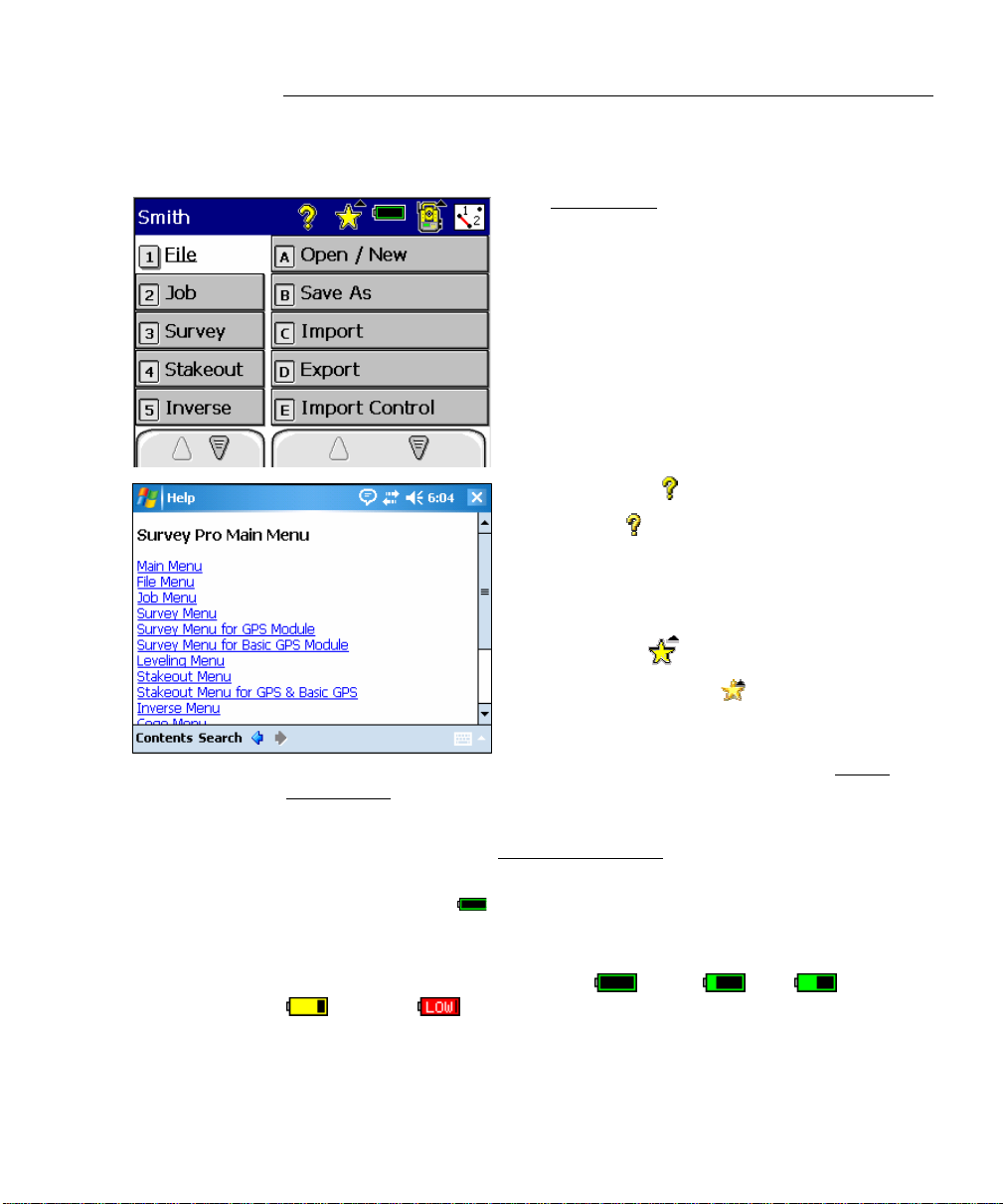
Main Menu
The Main Menu is the starting point where
all the other Survey Pro screens described in
this manual are accessed.
The area at the top of the screen is called the
command bar. The small buttons in the
command bar are used as follows:
Online Help
Tapping the button opens the online help,
which allows you to access information
similar to the information you would find in
the reference manual for each screen.
Quick Pick
The Quick Pick button is used to quickly
access any of a variety of commonly-used
Survey Pro routines. The list of routines
available is customizable using the Quick
Pick Editor (Page R-442).
The User’s Manual also contains more information on using the
Quick Pick button and Quick Pick Editor
.
Battery Level
The battery icon indicates the condition of the data collector’s
rechargeable battery. The icon has five variations depending on the
level of charge that is remaining:
25% and 5%.
100%, 75% 50%,
R-3
Page 12
Survey Pro Reference Manual
Tapping the battery icon is a shortcut to the Microsoft Power Settings
screen. You can view the online help for this screen on a Ranger
300X/500X by tapping
then
, or on a Ranger by tapping .
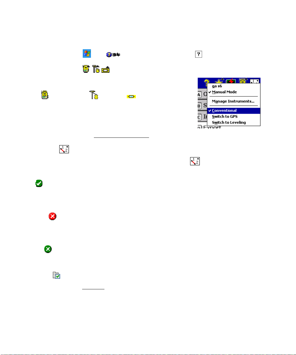
Surveying Mode
The instrument icon indicates which collection mode the
software is running in. There are three possible surveying
modes:
this icon will open a list of options to do any of the following:
Conventional, GPS, and Leveling. Tapping
• Switch to another instrument mode.
• Select a different instrument profile.
• Quickly access the Instrument Settings
screen (Page R-38).
Map View
A map view of the current job can be displayed by tapping the
button. This screen is described on Page R-444.
OK
This button performs the desired action then closes the current
screen.
Cancel
This button is red in color and closes the current screen without
performing the action intended by the screen.
Close
This button is green in color and closes the current screen.
Settings
This button opens the Settings screen associated with the current
screen.
R-4
Page 13

Main Menu
GPS Status
This is used to view the current status and access the settings for a
GPS receiver when using the GeoLock feature (Page R-162). It is
only available from the Remote Control
when using a Trimble or Geodimeter robotic total station.
and Remote Shot screens
R-5
Page 14

Page 15

File Menu
The File Menu contains routines to transfer files between the data
collector and another device.
A: Open / New
B: Save As
C: Import
D: Export
E: Control Panel
F: Backup / Restore Job
F: Transfer
H: Register Modules
I: About Survey Pro
J: Exit
R-7
Page 16
Survey Pro Reference Manual
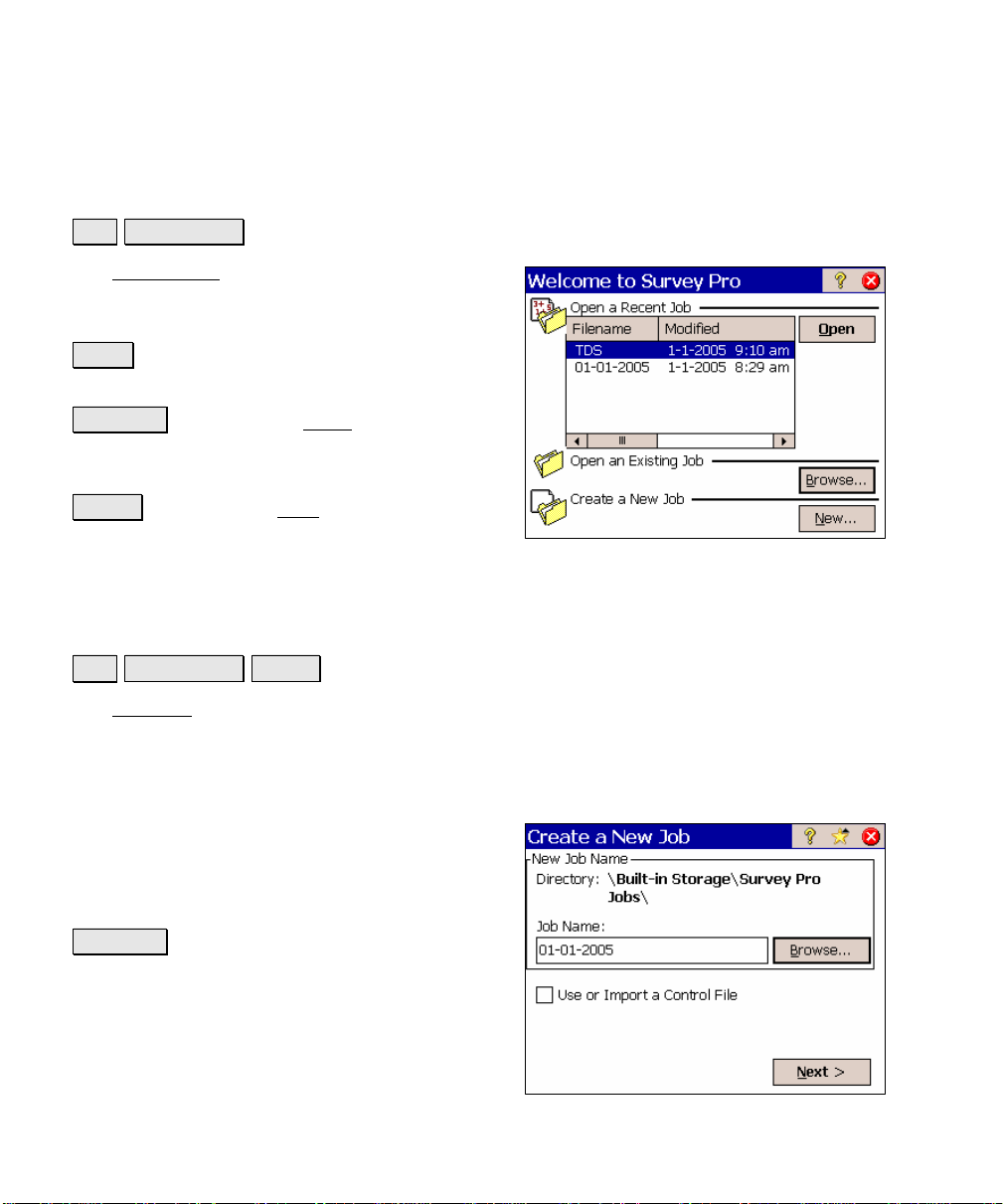
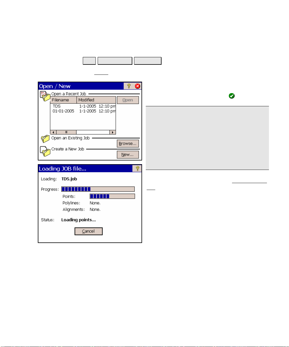
Open / New
File Open / New.
The Open / New screen is used to open an
existing job or create a new one. This screen
also appears when Survey Pro is first started.
Open : will open the job selected in the Open a
Recent Job list.
Browse… : will open the Open screen (Page R-
13) where an existing job to open can be
selected.
New… : will open the New screen (Page R-8)
where a new job can be created.
New Job
File Open / New New….
The New Job wizard is used to create a new job.
Create a New Job 1
Directory: displays the directory where the
current job will be stored.
Job Name: is where the name of the new job is
entered. The default name is the current date.
Browse… : allows you to select a different
directory where to store the new job.
Use or Import a Control File: when checked,
you can select an external control file or import
the points from a different job as control
points.
R-8
Page 17
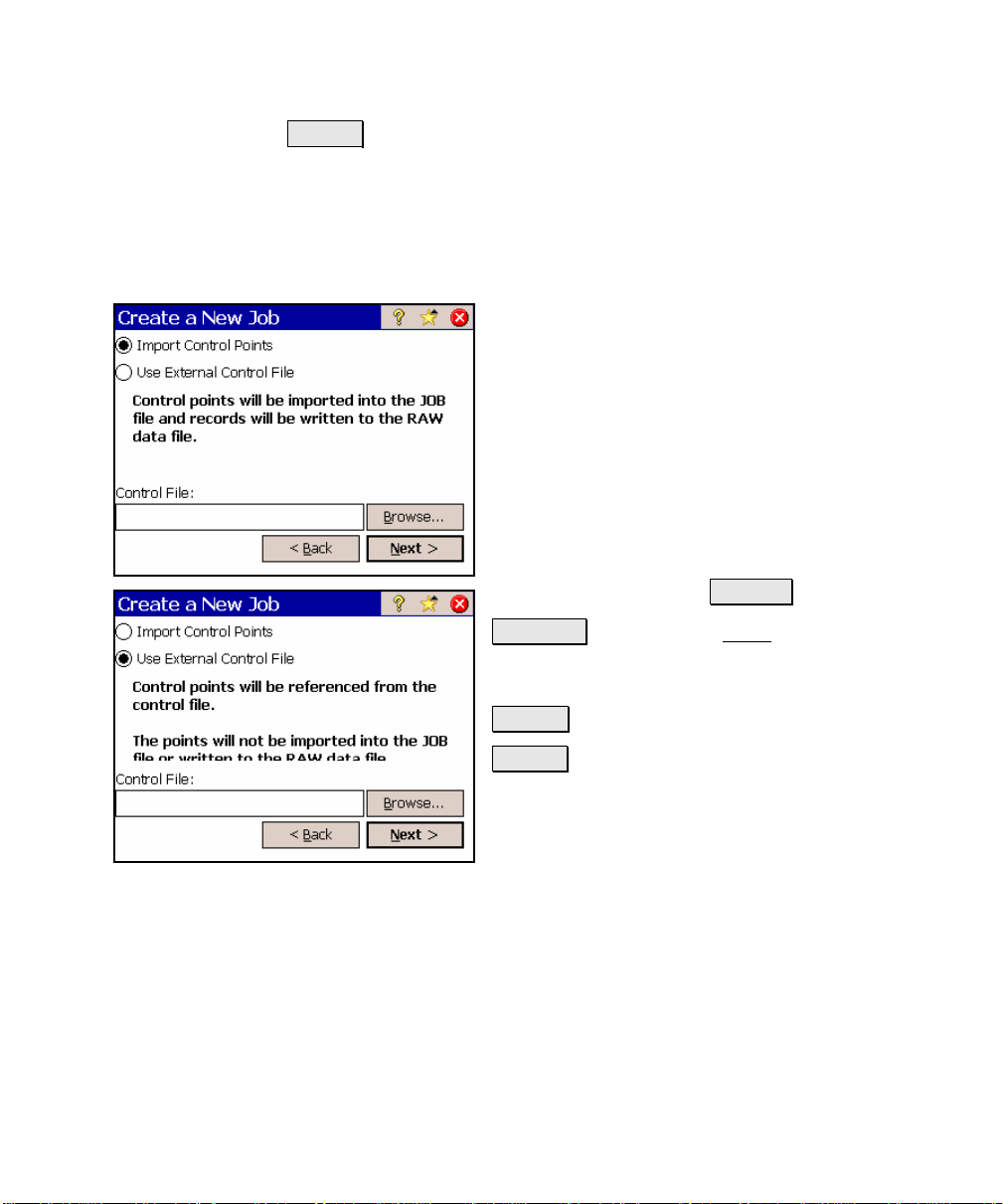
File Menu
Next > : opens the next screen. The screen that opens depends on if
a control file will be used.
Create a New Job 2 – (Imported or External Control File)
This screen will only open next when a control
file will be used or imported.
Import Control Points: When selected, the
points in the control file will be imported into
the new job.
Use External Control File: When selected, the
control points in the control file will be
accessible from the new job, but will not be
imported.
Control File: displays the path and control file
name selected with the Browse… button.
Browse… : will open the Open screen (Page R-
13) where an existing job can be selected as a
control file.
< Back : returns you to the previous screen.
Next > : opens the next screen.
R-9
Page 18
Survey Pro Reference Manual
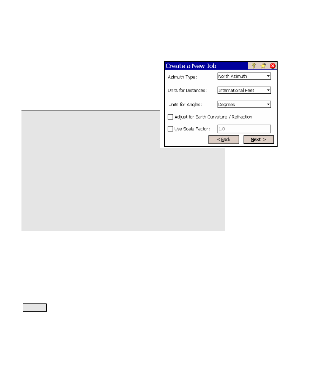
Create a New Job 3
Azimuth Type: specifies if you are surveying
with a North Azimuth or South Azimuth.
Units for Distances: specifies if your distances
will be entered in International Feet, U.S. Feet,
or Meters.
Note: You can enter a distance in any distance
field in units other than what is set for the job
by appending the distance value with the
following characters:
y f or ft or ift International Feet
y usf or usft US Survey Feet
y i or in Inches
y m Meters
y cm Centimeters
y mm Millimeters
y c or ch Chains
Once the cursor leaves that field, the distance will be converted
automatically. (A space between the value and the unit abbreviation
is optional.)
Units for Angles: specifies if angles will be entered in Degrees or
Grads.
; Adjust for Earth Curvature / Refraction: when checked, the
elevations recorded from all shots will be adjusted to compensate for
earth curvature and refraction.
; User Scale Factor: when checked, all horizontal distances when
taking shots will be adjusted by the scale factor entered here.
Next > : opens the final screen, which can be one of two different
possible screens depending on if a control file is being imported.
R-10
Page 19
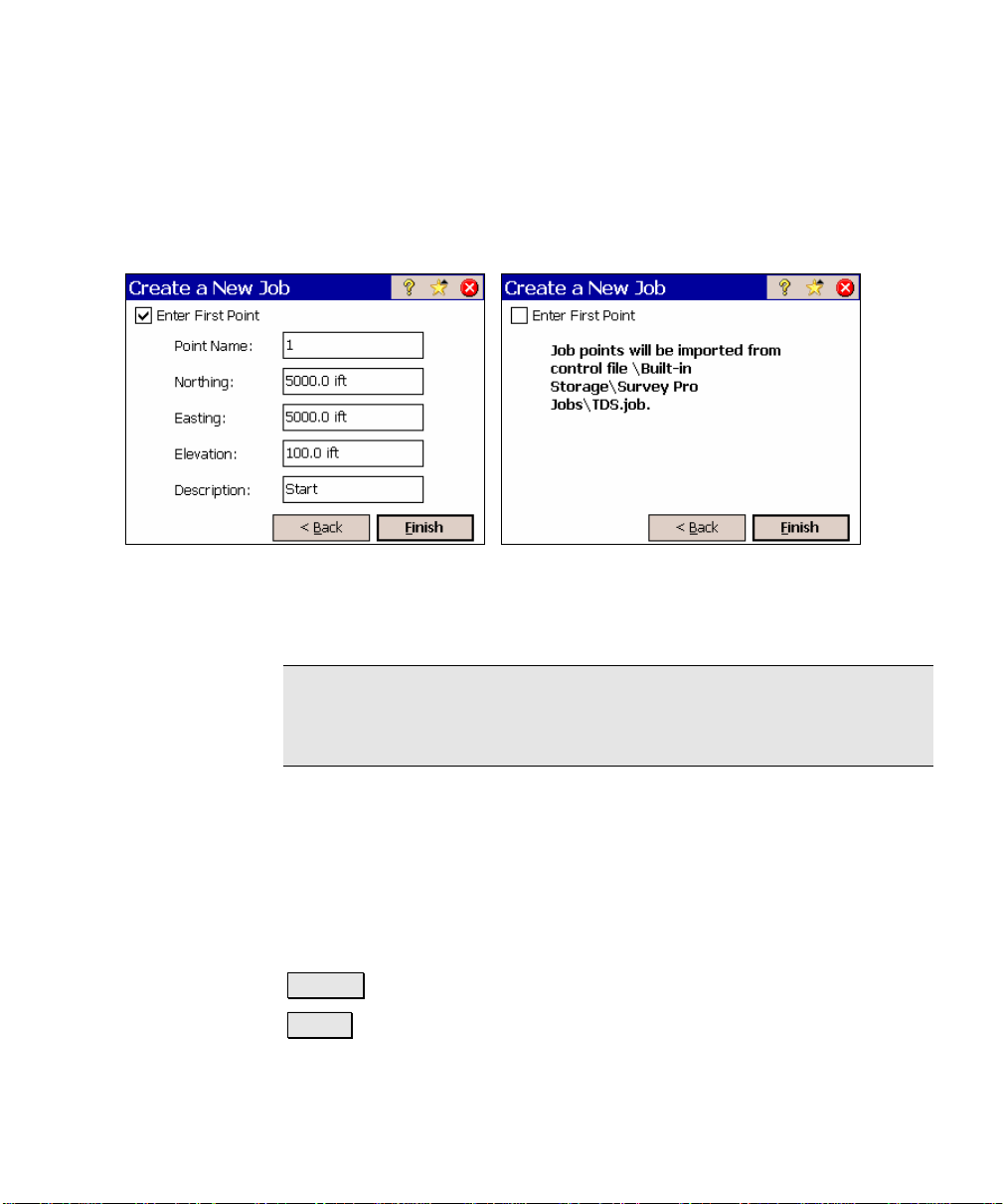
Create a New Job 4 – (Imported Control File)
This screen will only open when a control file is being import ed.
Screen when checkbox is unchecked. Screen when checkbox is checked.
Enter First Point: when this box is checked, the additional fields will
appear allowing you to create a new point.
File Menu
Note: Although all new jobs must have at least one point, creating a
new point when importing a control file is optional since p oi nts are
already being loaded into the job in the form of control points.
Point Name: is the name of the initial point.
Northing: is the Y-coordinate of the initial poi n t.
Easting: is the X-coordinate of the initial point.
Elevation: is the elevation of the initial point.
Description: is the description of the initial point.
< Back : returns you to the previous screen.
Finish : stores a new job file and raw data file using the specified
information.
R-11
Page 20
Survey Pro Reference Manual
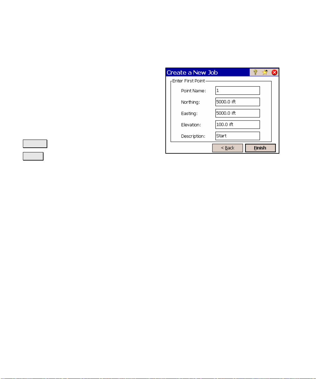
Create a New Job 5 – (External or No Control File)
Point Name: is the name of the initial point.
Northing: is the Y-coordinate of the initial
point.
Easting: is the X-coordinate of the initial point.
Elevation: is the elevation of the initial point.
Description: is the description of the initial
point.
< Back : returns you to the first screen.
Finish : stores a new job file and raw data file
using the specified information.
R-12
Page 21
Open
File Open / New. Browse….
The Open screen is used to open an existing job.
A list of all the jobs in the current directory is
displayed. Simply tap on the job name that
you want to open and then tap
Note: TDS CR5 files can be opened just like
any Survey Pro JOB file. When a CR5 file is
opened, it is automatically converted and
stored to a JOB file with the same name. If a
matching RW5 raw data file exists, it too will
be converted and saved to a Survey Pro RAW
file with a note inserted indicating that the
conversion took place.
When a job is being opened, the Loading JOB
file screen will open and display the status of
the loading process.
File Menu
.
R-13
Page 22
Survey Pro Reference Manual
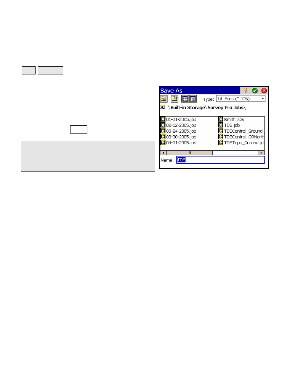
Save As
File Save As.
The Save As screen allows you to save a copy of the current job under
a new name. The copy that is created will then
become the current job.
The Save As
found in the Windows operating system.
Simply enter a new name for the current job
and then tap the Save button.
Note: It is not necessary to include the .JOB
extension since it will automatically be added
for you.
dialog box is identical to that
R-14
Page 23

File Menu
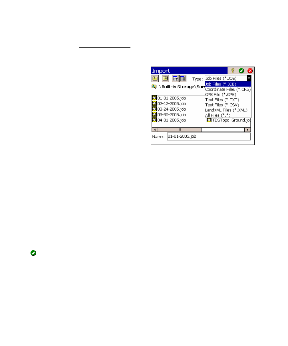
Import
File Import.
The Import screen is used to add the points from another source into
the current job or import the data from a LandXML file to the current
job.
Warning: Coordinate values can change when they are imported!
Importing coordinates from any source other than a JOB file requires
that the distance units used in the source file be specified. It is not
necessary to specify the distance units when importing coordinates
from a JOB file since those units are written within the file.
If importing coordinates where the distance units in the source file
are different than the distance units for the current job, the imported
coordinates will be converted to the current job’s distance units when
they are imported. This is normally the desired result, but it can
cause a problem if any distance units were set incorrectly. This
situation can most commonly occur when working with International
Feet and US Survey Feet where the conversion from one to the other
is not always obvious.
Usually the difference between International Feet and US Survey
Feet is negligible (2 parts per million), but when dealing with State
Plane or UTM mapping plane coordinates, which are often very large
in magnitude, the difference can be substantial if the coordinates are
converted from one format to the other.
If importing coordinates from a source, such as an HP 48, where you
are not sure if the units are in International Feet or US Survey Feet
into a job that is set to International Feet or US Survey Feet, you will
usually just want to import them without any conversion being
performed. To do this, be sure to select the same distance units for
the source file as those set for the current job.
R-15
Page 24
Survey Pro Reference Manual
Coordinates from a variety of file types can be imported into the
current job. The first Import Coordinates
from the file types listed below. The next screen that opens depends
on the selection made here.
• Job Files (*.JOB): import coordinates from
another Job file.
• Coordinate Files (*.CR5): import
coordinates from a TDS CR5 coordinate
file.
• GPS Files (*.GPS): import coordinates
from a TDS GPS coordinate file.
• Text Files (*.TXT): text files can cont ain
coordinates in several different possible
formats. The Import ASCII Wizard
to define the format of the text file being imported.
• Text Files (*.CSV): this is a simplified text file import routine
where the source file is comma delimited and has a *.CSV
extension.
• LandXML Files (*.xml): imports points, alignments, polylines,
and parcels from a LandXML file.
screen is used to select
is used
Import *.JOB Coordinates
When importing coordinates from another *.JOB file, the Import
Coordinates screen is used, described above.
A list of all the jobs available in the current directory is displayed.
Simply tap on the job name that you want to import and then tap
the
button. The points in the selected job will be added to the
points in the current job.
R-16
Page 25
File Menu
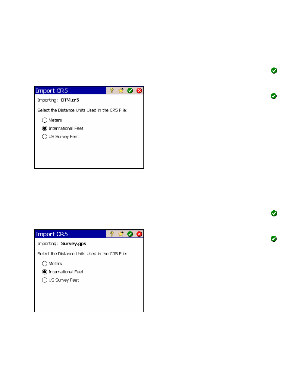
Import *.CR5 Coordinates
When importing a CR5 file, you will first be prompted to select the
layer where you want the new data stored. Select a layer and tap
to continue.
In the next screen, select the distance units
that the coordinates were stored in and tap
Import *.GPS Coordinates
.
When importing a GPS file, you will first be prompted to select the
layer where you want the new data stored. Select a layer and tap
to continue.
In the next screen, select the distance units
that the coordinates were stored in and tap
When importing coordinates from both a TDS
CR5 and GPS file from the same job, the GPS
coordinate will be linked to the coor dinates in
the CR5 file. For more information on this,
refer to the GPS User’s Guide.
R-17
.
Page 26
Survey Pro Reference Manual
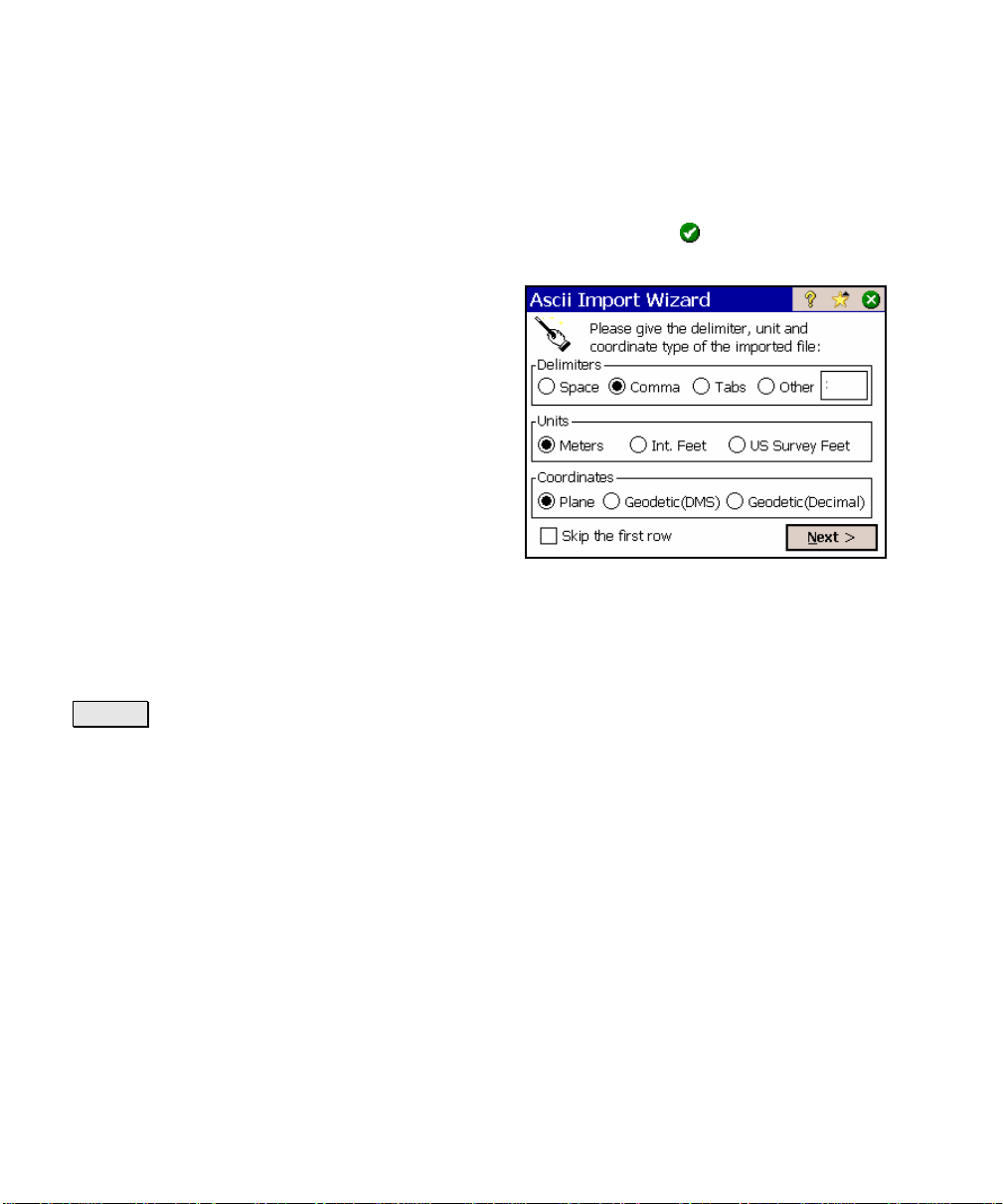
Import *.TXT Coordinates
When importing a TXT file, you will first be prompted to select the
layer where you want the new data stored. Select a layer and tap
to continue.
Since the coordinates in an ASCII TXT file can
be stored in a variety of formats, two screens
are used to define the format of the file that is
being imported once a layer is selected. The
source TXT file can contain either plane
coordinates or geodetic coordinates.
Delimiters: is the character that separates
each column of text in the ASCII file.
Units: are the units that the distances in the
file were stored in.
Coordinates: is used to specify if the
coordinates are plane coordinates, geodetic coordinates in degreesminutes-seconds format, or geodetic coordinat es in decimal format.
; Skip the first row: should be checked if the first line in the ASCII
file contains non-coordinate information, such as a heading.
Next > : opens the second screen.
R-18
Page 27
File Menu
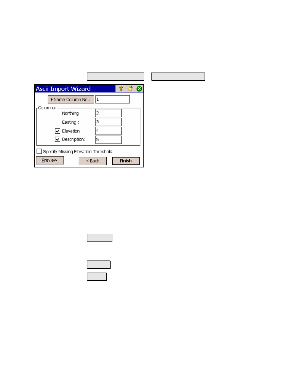
Import *.TXT Coordinates – Screen Two
Name Column No. / Start Point Name.
When the first option is selected here, the
column number used for the name field in the
*.TXT file is specified here. When the second
option is selected, it is assumed that the *.TXT
file does not contain point names and will
assign the first point the name specified here
and increment to the next available point name
for the remaining points.
Columns: is where the column number for each
specified coordinate exists in the source *.TXT
file. The coordinates types displayed here can
either be for plane coordinates or geodetic coordinates depending on
the selections made in the previous screen. If a coordinate has a
checkbox, which is unchecked, it is assumed that the source *.TXT
file does not contain columns for that type of coordinate.
; Specify Missing Elevation Threshold: if the source file was
created from coordinates with no elevations, but the file contains an
elevation column with values, such as 0, check this box and indicate
the value in the field that will appear to the right.
Preview : opens the ASCII Import Preview window containing all the
point data that will be imported. This is useful to check for errors
before actually importing new data.
< Back : returns to the previous screen.
Finish : imports the new point data into the current project.
R-19
Page 28
Survey Pro Reference Manual
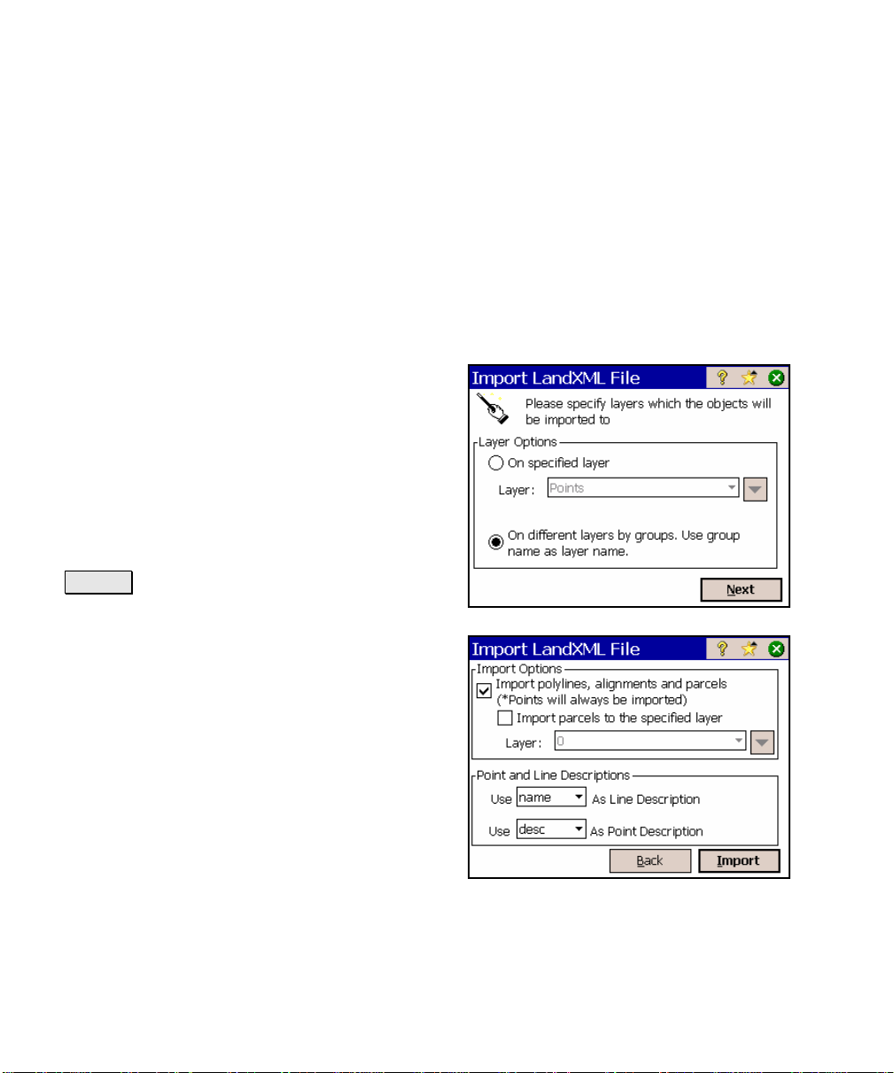
Import LandXML Coordinates
Points, alignments, polylines, and parcels can be imported from a
LandXML file.
The way the LandXML data is imported depends on how the data is
stored in the source file and how the settings are configured in the
two screens described below.
Consult the User’s Manual for more information on the conditions
that affect how the data is imported.
On specified layer: will import all the data on
the specified layer.
On different layers by groups: will import
points, alignments, and parcels to layers
named by the group name for the data in the
source file. If the group name is an invalid
layer name (e.g., it is empty or contains invalid
characters), the data will be stored to the
active layer.
Next > : opens the second configuration
screen.
Import polylines, alignments and parcels:
When this is checked, polylines, alignments
and parcels will be imported, as well as the
points. When unchecked, only the points will
be imported.
Import parcels to the specified layer: When
this is checked, imported parcels will be stored
to the selected layer. If unchecked, parcels will
be stored to the layer specified in the p r evious
screen.
For more information on how parcels are
imported, consult the User’s Manual.
Point and Line Descriptions: You can select what information to use
as the description for imported lines and points in the corresponding
two fields.
R-20
Page 29
File Menu
Lines can either be assigned the name or description from the source
file and points can either be assigned the description or code from the
source file.
Back : returns to the previous screen.
Import : imports the specified data into the current project. A
results screen will open listing the details of the imported data.
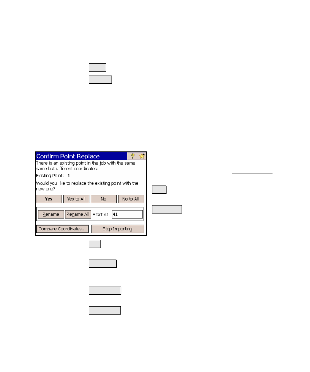
Confirm Point Replace
If a point being imported has the same name and the same
coordinates as a point that is already in the current job, it is ignored
and a message will be displayed after the remaining points are
imported to indicate this.
If an imported point is encountered with the
same name, but with different coordinates as a
point in the current job, the Confirm Point
Replace screen will open.
Yes : will replace the point in the current job
with the point being imported.
Yes to All : will replace the point in the current
job with the point being imported and perform
the same action for any remaining duplicate
points.
No : will not import the duplicate point, keeping the coordinates for
the existing point unchanged.
No to All : will not import the duplicate point, keeping the
coordinates for the existing point unchanged and perform the same
action for any remaining duplicate points.
Renumber : will store the new point in the current job under the
name specified in the Starting At field.
Renum All : will store the new point in the current job under the
name specified in the Starting At field and perform the same action for
any remaining duplicate points, storing them with the next available
point name.
R-21
Page 30
Survey Pro Reference Manual
Start At: is the point name assigned to the imported point when
using the Renumber or Renumber All functions.
Compare coordinates… : will open a dialog box showing the
coordinates for the duplicate points to assist in making a decision of
how to handle the new point.
Stop Importing : will not import the current duplicate point and will
stop importing any remaining points. All previous points will still be
imported into the current job.
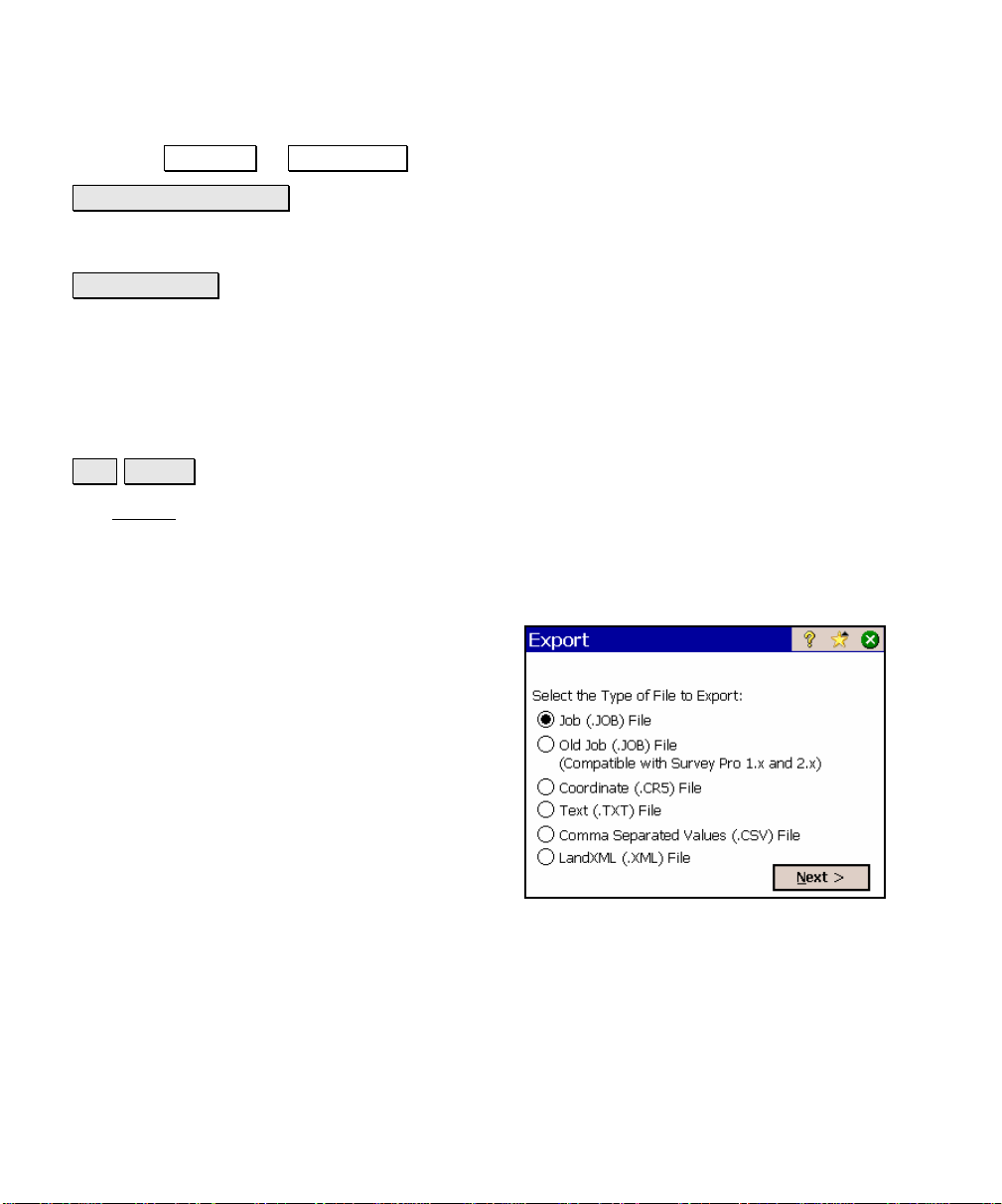
Export
File Export.
The Export screen allows you to export selected points from the
current job to a new job or to a coordinate file in another format. You
can also export all the objects in the current job to a LandXML file.
This first screen is used to specify the type of file that you want to
export data to.
Job (.JOB) File: when selected, the points are
exported to a TDS JOB file.
Old Job (.JOB) File: when selected, the points
are exported to a TDS JOB file that is
compatible with versions of Survey Pro earlier
than 3.0.
Coordinate (.CR5) File: when selected, the
points are exported to a TDS CR5 coordinate
file format.
Text (.TXT) File: when selected, the points are
exported to an ASCII text file.
Comma Separated Values (.CSV) File: when selected, the points are
exported to an ASCII text file that is comma delimited and the file is
automatically given a *.CSV extension.
LandXML (.XML) File: when selected, the data is exported to a
LandXML file and automatically given an *.XML extension.
R-22
Page 31

File Menu
Next > : opens the next screen, which is determined by the selected
file type.
Export – Screen Two
The second Export screen will open for any file type that was selected
in the previous screen except LandXML. This screen is used to select
the points from the current project that you want to export to the
selected file type. (Exporting to a LandXML file is described later.)
To/From… : Opens the Point List screen (Page
R-443) where a point list can be created.
Tap Points… : allows you to select the points to
export by tapping them from a map view.
: The power button provides additional point
selection options, which include selecting all
control points, all non-control points and
selection by description.
< Back : returns to the previous screen.
Next > : opens the next screen, which is
determined by the selected file type.
Export *.JOB Coordinates
When exporting to another *.JOB file, the Save As screen is opened
where the file name and location is entered for the new *.JOB file.
Export Old *.JOB Coordinates
This option functions exactly as the Export *.JOB routine, described
above, only the resulting file is written to be compatible with the
Survey Pro Version 2.x format, and earlier.
R-23
Page 32

Survey Pro Reference Manual
Export *.CR5 Coordinates
The Export CR5 dialog box will open when exporting coordinates to a
TDS CR5 coordinate file.
CR5 File Options: specifies if the resulting file
should be Sequential or Non-Sequential. (The
HP 48 data collector can only use sequential
coordinate files.)
< Back : returns to the previous screen.
Export : exports the selected coordinates to the
new CR5 file.
Export *.TXT Coordinates
Since the coordinates in an ASCII *.TXT file can be stored in a
variety of formats, two screens are used to define the format of the
resulting file.
Delimiters: is the character that separates
each column of text in the ASCII file.
Coordinates: is used to select if the resulting
coordinates should be plane coordinates,
geodetic coordinates in degrees-minutesseconds format, or geodetic coordinates in
decimal format.
Units: are the distance units that will be
written to the resulting TXT file. These units
are automatically set to the same units that
are set for the current job.
; Headers in the first row: When checked, a heading describing
each column is inserted in the first row. For example, the foll owing
header could be inserted:
Name,Northing,Easting,Elevation,Description
< Back : returns to the previous screen.
R-24
Page 33

File Menu
Next > : opens the second screen.
Export *.TXT Coordinates – Screen Two
Select the desired order and format for the
resulting TXT file from the list of options.
Finish : exports the selected points to the TXT
file.
Export *.CSV Coordinates
This routine is identical to the Export *.TXT Coordinates routine,
described above with the exception that the formatting for the
exported file is automatically set to comma delimited and the
extension for the file name will be *.CSV.
R-25
Page 34

Survey Pro Reference Manual
Export LandXML (.XML) File
Unlike the other export routines, which only export points, the
LandXML export routine allows you to export points along with
polylines and alignments.
Export polylines and alignments: will export
the points in the current project as well as any
polylines and alignments. If this is unchecked,
only the points will be exported.
Export polylines on the specified layer as
parcels: will export the polylines on the
selected layer as parcels. (Polylines on other
layers will still be exported, only not as
parcels.)
Export point description as: allows you to
select to export the point descriptions as
LandXML descriptions or codes.
Import Control Points
File Import Control.
The Import Control screen is used to manage a
control file for the current job.
Import… : opens the Open screen (Page R-13)
where an existing job can be selected as a
control file. The control points will then be
imported into the current job and stored to the
CONTROL layer.
External Control File: displays the path and
file for the current external control file (if one
is used).
Clear : clears the current external control file.
Browse… : opens the Open screen (Page R-13) where an existing job
can be selected as an external control file. (If any point names in the
R-26
Page 35

File Menu
external control file are also used in the current job, the control file
cannot be used.)
Backup / Restore Job
File Backup / Restore.
The Backup / Restore wizard is a series of
screens that are used to backup or restore all
the files associated with the current job.
The routine also gives you the option of storing
a snapshot of a customized map view to the
archive. This can then be used to visually
identify an archive.
Any number of backups can be created for a
particular job. All the existing backups for the
current job are listed in the main Backup /
Restore screen, along with other information
including the date the backup was created, the number of fil es stored
in the archive and if the archive includes a snapshot. Archives that
include a snapshot are shown with a
snapshot have a
been created, but a backup has not yet been stored to it.
icon. The icon is used when a new archive has
icon, while those without a
All of the backups for a particular job are physically stored to a single
compressed file located in the \Built-in Storage\Survey Pro Jobs
directory on the data collector. This file will have the same filename
as the current job, only the *.Backup extension is appended to the
name. For example, the backups for a job with a filename of
Smith.Job will be stored in a file called Smith.Job.Backup.
New Archive… : opens the New Archive dialog box where a name is
entered for the new backup archive being created. Once created, an
empty archive will be listed in the main Backup / Restore
which can then be selected to backup the current job.
Delete Archive… : opens a prompt asking if you are sure. If you select
Yes at the prompt, the archive selected from the main Backup /
Restore screen will be deleted.
screen,
R-27
Page 36

Survey Pro Reference Manual
Properties… : opens the Archive Properties screen.
Backup: when selected, tapping Next> will begin the backup
routine where the data for the current job will be stored to the
selected archive.
Restore: when selected, tapping Next> will begin the restore
routine where the data from the selected archive will be restored,
overwriting the current job.
Next> : opens the next screen.
Backup / Restore - Archive Properties
File Backup / Restore Properties….
The Archive Properties screen lists the files
stored within the selected archive along with
other information.
The file sizes listed in this screen are in bytes.
Since all backup archives are compressed, the
file sizes displayed represent the compressed
files, or the amount of space actually being
used by the file(s) on the data collector.
View Snapshot… : will display the snapshot
from the selected archive if one was included
when the archive was originally created.
R-28
Page 37

File Menu
Backup / Restore – Backup
When performing a backup, all the files
associated with the current job are listed and
will be included in the archive.
; Create Snapshot: When checked, the next
screen will prompt you to create a snapshot of
the current job’s map view, which will then be
included in the archive.
< Back : returns to the previous screen.
Backup : opens the next screen.
Backup / Restore - Create a Snapshot
The Create a Snapshot screen is a map view
that is used to configure the map as desired
and the resulting image will be saved in the
archive as a snapshot along with the job files.
: will create the archive along with a
snapshot of the map as it is configured on the
screen.
: will create the backup archive without a
snapshot.
R-29
Page 38

Survey Pro Reference Manual
Backup/Restore – Restore
When restoring the job files from an archive,
the archived files will replace the existing files
of the current job.
Warning: If you do not want to lose any new
data that was collected after the archive being
restored was created, you should first backup
the current job to a new archive before
restoring an older archive.
< Back : will return to the previous screen.
Restore : will restore the backed up job from the selected archive.
The current job is then deleted and replaced by the backup job.
R-30
Page 39

File Menu
Transfer
File Transfer.
The Transfer screen allows you to transfer files between the data
collector and another device running TDS software.
personal computer that is running Windows CE Services.
• Geodimeter 600: if you are connecting to a Geodimeter 600-
series total station running TDS onboard software.
COM Port: specifies which COM port you are using on the local
machine.
Connecting to: specifies which device you are
communicating with from the following options:
• HP48: if you are connecting to a
Hewlett Packard HP48 calculator.
• Husky: if you are connecting to a Husky
FS-series data collector.
• Ranger / TSCe / ACU / Pocket PC: if you
are connecting to any of the devices
listed.
• Windows PC: if you are connecting to a
Baud Rate: specifies the communications speed. The baud rate must
match in both units for successful communications.
Parity: specifies the parity. The parity must match in both units.
When in doubt, select None here. All transfers are controlled from
the PC when in this special mode.
Enter Server Mode : places the data collector in server mode where all
file transfers are controlled from a PC running either TDS Survey
Link or TDS ForeSight. Tapping Cancel will disconnect server mode.
Send File… : will open the Open dialog box where the file that you
want to send can be selected. Once selected, the file is sent from the
data collector to the specified device. A progress bar will be displayed
R-31
Page 40

Survey Pro Reference Manual
that indicates how much of the file has been transferred. Tapping
Cancel will stop the file transfer.
Note: The Send routine should be initiated shortly after issuing the
receive command on the other device.
Receive File… : allows you to receive a file from another device. This
should be tapped prior to issuing the Send command on the other
device. Tapping Cancel will stop the file transfer.
Register Modules
File Register Modules.
The Register Modules screen is used to upgrade the Survey Pro
software. Refer to the User’s Manual for more information on
registering additional modules.
If no modules have been registered, Survey Pro
will run in Demo Mode. When running in
Demo Mode, users are able to test and use
every routine available in the software, as if
the Survey Pro Max module was purchased.
Although, Demo Mode limits all jobs to no more
than 25 points. If a job exists on the data
collector that contains more than 25 points, it
cannot be opened while running in Demo
Mode.
Registered: Indicates that the corresponding
module has been added.
R-32
Page 41

Enter Registration Code : Opens the Register
screen, shown here, where the registration
number for a particular module can be entered.
About Survey Pro
File About Survey Pro.
The About screen displays the version of the
Survey Pro software and the versions of several
of the Survey Pro software files, which can be
updated from the TDS Website.
File Menu
Hardware Information : is a shortcut to the
Microsoft System Properties screen.
Exit
File Exit.
This will close the Survey Pro software and return you to the
operating system installed on your data collector.
R-33
Page 42

Page 43

Job Menu
A: Settings
B: Edit Points
C: Edit Polylines
D: Edit Alignments
E: Auto Linework
F: View Raw Data File
G: View DTM
H: Manage Layers
I: Job Information
J: Calculator
R-35
Page 44

Survey Pro Reference Manual
Settings
Job Settings.
See Page R-94 if running in GPS mode.
The Settings
where each individual screen contains different types of settings.
There are two ways to navigate to the various screens. The first
method is to tap the
screens and then tap on the desired screen from the list to open it.
An alternate method is to tap the buttons to the side of the screen
title, which will open the previous or next screen respectively.
Repeatedly tapping either of these buttons will cycle through all the
available screens.
screen actually consists of several separate screens
button to drop down the list of available
Instrument Settings
Job Settings Instrument Settings.
The Instrument Settings screen is actually the
first of multiple screens used to identify and
configure the instrument(s) you are using with
Survey Pro. The correct settings must be
configured for successful communications
between the data collector and the instrument.
The upper portion of the first Instrument
Settings screen lists the names of all the
instrument profiles on the data collector. The
other columns list the COM Port, Brand, and
Model of the instrument defined in each profile.
Manual Mode: is a special profile that cannot be deleted. When
activated, all surveying is performed without being connected to an
instrument and all shot data must be entered manually.
R-36
Page 45

Job Menu
Note: When running in leveling mode, the Instrument Settings… can
be selected for Manual Mode to open the Level Method screen
described on Page R-41.
Instrument Settings : opens the next Instrument Settings screen
where the settings in the selected instrument profile can be modified.
Note: When editing an existing instrument profile, you cannot modify
the instrument brand or model.
Create New Instrument : opens the next Instrument Settings screen
where you can configure the settings for a new instrument and create
a new instrument profile.
Activate : activates the selected instrument profile.
GeoLock : opens the GeoLock Settings screen (Page R-162).
Delete : deletes the selected instrument profile.
Import : imports an instrument profile from an instrument profile
file that was previously loaded on the data collector.
Export : saves the selected instrument profile to a file, which can
then be transferred to another data collector and then imported.
Warning: Performing a hard reset on the data collector will result in
all the user-created instrument profiles to be deleted. It is
recommended that all instrument profiles be exported to files so in
the event of a hard reset they can be recovered using the Import
routine.
R-37
Page 46

Survey Pro Reference Manual
Instrument Settings – Screen Two
The second Instrument Settings screen opens whenever a new
instrument profile is being created, or when an existing profile is
being edited.
The options available on this screen will vary slightly dependin g on
the total station model selected.
Name: is the name of the instrument profile
being created or changed. This is the name
that appears in the list on the first Instrument
Settings screen.
Brand: is where you specify the manufacturer
of the instrument that you are using from a
dropdown list.
Model: is where you specify the model of the
instrument that you are using from a
dropdown list.
Instrument Settings… : opens the settings that
are specific for the selected total station.
Send to Instrument : (applicable only on specific total stations) will
send the selected instrument settings to the total station. This is
particularly useful with robotic total stations after the total station
has been reset.
Serial Port: is the serial port on the data collector used for
communications with the total station. (Bluetooth can also be selected
for wireless communication between the data collector and a
compatible total station.)
Baud Rate: is the speed at which communication occurs with the
total station. This must match the baud rate configured within the
total station.
Parity: is the parity used for communication with the instrument.
This must match the parity setting configured within the total
station.
PIN: (applicable only when using Bluetooth with a Recon and a
supported total station) is the Personal Identification Number that
R-38
Page 47

Job Menu
was entered in the total station. These numbers must match for
successful communications.
Bluetooth… : (applicable only when using Bluetooth with a supported
total station) accesses the Bluetooth configuration screen that comes
with the Bluetooth driver software where you ca n quickly check or
change the virtual COM port and favorites.
Note: See the User’s Manual for more information on configur ing
Bluetooth with a supported total station.
Defaults : will set the Serial Port, Baud Rate and Parity to their default
values based on the selected total station.
Instrument Settings… : accesses the settings that are specific for the
selected total station.
Send to Instrument : (applicable only on specific total stations) will
send the selected instrument settings to the total station. This is
particularly useful with robotic total stations after the total station
has been reset.
R-39
Page 48

Survey Pro Reference Manual
NOTICE:
The settings that are available after tapping the
Instrument Settings… button directly control the settings that are
built into the selected total station. Since total station manufactures
release new models every year, TDS cannot maintain the necessary
set up documentation for every existing model and the models that
are not yet available. The set up procedure for your particular total
station is better handled by the total station manufacturer, or your
instrument’s dealer.
If you have specific questions on the set up of your total station y ou
should refer to the documentation that was included with your total
station. The numbers listed below are provided for your c onv enience:
Trimble: 800-538-7800
Zeiss: 800-538-7800
Geodimeter: 800-538-7800
Leica: 800-327-4773
Nikon: 516-547-8500
R-40
Pentax: 800-729-1419
Topcon: 800-223-1130
Page 49

Job Menu
Level Method
Job Settings Instrument (select Manual Mode) Instrument Settings…
The Level Method screen is used to select the
leveling method you want to use while running
in leveling mode and while using Manual Mode.
This will affect the type of data you are
prompted for when taking shots.
Three Wire: Prompts for shot data will require
upper, center, and lower wire readings.
Single Wire: Prompts for shot data will require
center wire readings only.
Electronic: Prompts for shot data will require a
vertical and horizontal distance.
Trigonometric: Prompts for shot data will require a zenith angle and
horizontal distance.
Units Settings
Job Settings Units.
The Units Settings card defines the units that
are used within the software, sent from the
total station, entered from the keypad and
displayed on the screen. You can select the
following settings for your project from the
following dropdown lists.
Units for Distances: defines the units used for
length as Meters, International Feet, or US
Survey Feet.
R-41
Page 50

Survey Pro Reference Manual
Note: You can enter a distance in any distance field in units other
than what is set for the job by appending the distance value with the
following characters:
y f or ft or ift International Feet
y usf or usft US Survey Feet
y i or in Inches
y m Meters
y cm Centimeters
y mm Millimeters
y c or ch Chains
Once the cursor leaves that field, the distance will be converted
automatically. (A space between the value and the unit abbreviation
is optional.)
Warning: When creating a new job, it is important that the Units for
Distances field be set to the correct units. This allows you to
seamlessly switch between different units in mid-job.
Problems can arise if these units are inadvertently set to the incorrect
units when entering new data. For example, assume a new job was
created by hand-entering a list of coordinates where the job was set to
International Feet and the coordinates being entered were in US
Survey Feet. Now assume you created another new job and correctly
set it to US Survey Feet. If you then imported the hand-entered points
from the other job, they would be converted to different units when no
conversion should have taken place. Depending on the magnitude of
the imported coordinates, the error after the conversion could be
significant.
Units for Angles: defines the units used for angles as Degrees or
Grads (gons).
Display Directions as: will display directions as a Bearing or
Azimuth.
Azimuth type: defines if you are using a North Azimuth or a South
Azimuth.
R-42
Page 51

Job Menu
Format Settings
Job Settings Format.
The Format Settings card defines the number of places beyond the
decimal point that are displayed for various values in all screens, and
how stations are defined. (All internal calculations are performed
using full precision.)
Northings / Eastings: will allow you to display
from zero to six places passed the decimal point
for northing and easting values.
Elevations: allows you to display from zero to
six places passed the decimal point for
elevations.
Sq feet / meters: allows you to display from
zero to four places passed the decimal point for
square feet or square meter values.
Acres / Hectares: allows you to display from
zero to four places passed the decimal point for
acre or hectare values.
Distances: allows you to display from zero to six places passed the
decimal point for distances.
Angles: allows you to include from zero to four fractional seconds
with angle values.
Stations: allows you to display stations in any of the following
formats:
• 12+34.123: displays stations where the number to the left of
the + advances after traveling 100 feet or meters.
• 1+234.123: displays stations where the number to the left of
the + advances after traveling 1,000 feet or meters.
• 1,234.123: displays standard distances rather than stations.
R-43
Page 52

Survey Pro Reference Manual
Files Settings
Job Settings Files.
Description File: allows you to select a
description file to use with the current job.
; This file uses codes: check this box if the
description file contains codes and associated
descriptions. Leave the box unchecked if the
description only contains descriptions (no
codes).
Feature Code File: displays the selected
feature code file to use with the current j ob.
See the User’s Manual for more information on
feature codes.
Browse : Allows you to select a file to use with the current job.
Simply tap on the filename and then tap Open .
Clear : closes the currently selected file so that it is no longer used
with the current job.
R-44
Page 53

Job Menu
Surveying Settings
Job Settings Surveying.
The Surveying Settings card allows you to select various options that
affect how data collection is performed.
; Prompt for Description: When checked, a
prompt for a description will appear before any
new point is stored from only the routines
under the Survey
Note: Descriptions cannot exceed 16
characters.
; Prompt for Height of Rod: When checked,
a prompt for the rod height will appear before
any new point is stored.
; Prompt for Layer: When checked, a prompt to select a layer will
appear before any new point is stored from only the routines under
the Survey
menu (Page R-117).
menu (Page R-117).
; Prompt for Attributes: When checked, a prompt to select feature
information will appear before any new point is stored from only the
routines under the Survey
a feature file be selected from the Files Settings
above.
; Detect Duplicate Shots: when checked, a prompt will appear
before attempting to store a second shot to the sam e location. This
helps to catch when robotic total stations have lost lock while
surveying. The distance tolerances set in the Repetition Settings
screen are used in determining when two shots are at the same
location.
; Adjust for Earth Curvature / Refraction: when checked, the
elevations for new points are adjusted to compensate for the
curvature of the earth and refraction.
menu (Page R-117). This also requires that
card, described
R-45
Page 54

Survey Pro Reference Manual
; Survey with True Azimuths: automates the process of adjusting
the circle on the total station when traversing so th at you can survey
with azimuths rather than horizontal angles (see Page R-127).
; Use Scale Factor: when checked, horizontal distances to all new
points will be scaled by the factor entered here. (Elevations are not
affected.) This defaults to unchecked when a new job is created.
Calc. Scale : allows you to automatically compute the scale factor
from a selected map projection. If a mapping plane is not already
selected, you will first be prompted to select one.
; Prompt to Reset Scale on New Setups: if checked when a map
projection is selected and you set up over a new location, the specified
scale factor is compared to the scale factor defined for your current
location in the mapping plane. If the scale factor is different, you will
be prompted to use the new scale factor.
R-46
Page 55

Job Menu
Stakeout Settings
Job Settings Stakeout.
The Stakeout Settings card contains the setting that control how
stakeout is performed. (The settings available depend on if you are
running in conventional or GPS mode.)
; Stake “Corners,” Not Just Even
Intervals: when staking by stations,
locations where a line segment changes, such
as from a straight section to a curve, will also
be staked when this is checked.
; Stake Bisector of Non-tangent Corners:
When staking an offset to a centerline that
contains a corner, this option, when checked,
will stake the corner point where the two
offsets intersect.
; Always Start Stakeout With Coarse
Mode: When checked, the EDM mode toggle button found in all
stakeout screens will initially be set to coarse mode (fast shot). This
instructs the total station to measure distances faster, but with
slightly less accuracy.
; Use Manual Updating (Remote Control): When this is checked, a
Shot button in the stakeout screens must be pressed to take a shot.
When this not checked, shots are continuously taken in the stakeout
screens. (This is only valid when running in remote mode, using a
robotic total station.)
; Design Elevation from Offset Segment: Determines wher e the
cut/fill value is computed from in the Offset
screens when the Offset checkbox is checked and a non-zero offset is
entered. When checked, the cut/fill value is calc ulated from the design
elevation of the node you are staking to. When unchecked, the cut/fill
value is calculated from the design elevati on at the specified offset
location.
and Road Stakeout
R-47
Page 56

Survey Pro Reference Manual
Note: If the specified offset extends beyond the end of the road
profile, the cut/fill value is always computed from the design
elevation of the node you are staking to.
; Write Cut Sheet Data Only (No Store Point): When checked, as-
built points are not stored to the JOB file when staking points; only
the raw data is written to the RAW file.
; View from Gun to Rod (non-remote): When checked, the move
left or right information will be presented from the rod person’s point
of view. When unchecked it will be presented from the total station’s
point of view. (This option only applies when a robotic total station is
selected in the Instrument Settings
.)
; View from Rod to Gun (remote): When checked, the move left or
right information will be presented from the rod person’s point of
view. When unchecked it will be presented from the total station’s
point of view. (This option only applies when a non-robot total station
is selected in the Instrument Settings
.)
; Prompt for Layer: When checked, a prompt to select a layer will
appear before any new point is stored from only the routines under
the Stakeout
menu.
; Prompt for Attributes: When checked, a prompt to select feature
information will appear before any new point is stored from only the
routines under the Stakeout
file be selected from the Files Settings
menu. This also requires that a feature
card, described earlier.
Note: There is no Prompt for Description checkbox as in the Surveying
Settings card because you are always prompted for a description
when storing a point from a stakeout routine.
Use Perfect Stationing: When checked, staking locations will be
computed at perfect stationing intervals. For example, if your
starting station was 0+15 and your station interval was 100, your
next stakeout location will occur at 1+00 instead of 1+15.
Point Tolerance: this setting affects the Remote Staking
routine
(Page R-279). When performing Remote Stak eout, the final graphic
R-48
Page 57

Job Menu
screen that is displayed when you are near the stake point will occur
when you are within the distance to the stake point specified here.
Line Tolerance: this setting affects the Stake to Line
routine (Page
R-282). When staking to a line and the prism is located at a
perpendicular distance to the specified line that is within the range
set here, a message will state that you are on the line.
Horizontal Distance Tolerance: This setting affects the GPS staking
routines. When you are within the specified distance to the location
you are staking, you are considered on that location.
Turn gun to design point: only applies to motorized total stations.
The following options are available:
• 2D (HA only): A motorized total station will turn horizontally
toward the design point after tapping the Turn Gun button in
the particular stakeout screen.
• 3D (HA and ZA): A motorized total station will turn
horizontally and vertically toward the design point after
tapping the Turn Gun button in the particular stakeout
screen.
• Automatic 2D (HA only): A motorized total station will
automatically turn horizontally toward the design point when
the stakeout screen opens.
• Automatic 3D (HA and ZA): A motorized total station will
automatically turn horizontally and vertically toward the
design point when the stakeout screen opens.
Cut Sheet Offset stored: The cut sheet offset information can be
stored to the raw data file in either of the following formats when
performing any offset staking routine:
• Design Offset: when selected, a cut sheet report will list the
design-offset values.
• Actual Offset: when selected, a cut sheet report will list the
measured-offset values.
Display Directions As: will guide you to the GPS stakeout location
using one of the following formats:
R-49
Page 58

Survey Pro Reference Manual
• Northing / Easting: will suggest you Go South/Go North and Go
West/Go East
• Distance / Azimuth: will display the necessary Azimuth and
Distance to the stakeout location.
• Forward / Back: will suggest you go FORWD/BACK and Go
Left/Go Right when you are within 3 meters to the location.
When you are farther than 3 meters, a distance and azimuth
is used.
Level Settings
Job Settings Level.
The Level Setting screen is only available when running in leveling
mode. It is used to configure all of the settings for performing a level
loop. The scroll bar allows you to view additional settings.
BS1…BSn>FS1…FSn: This sequence requires
that you take all the shots for each set to the
backsight, turn to the foresight, and then shoot
all the shots for each set to the foresight.
[BS1 FS1>FS2 BS2]n: A single set in this
sequence requires that you shoot the backsight,
turn and shoot the foresight, shoot the
foresight again, turn and shoot the backsight.
Repeat for all remaining sets.
Number of Sets (n): is the number of sets you
want to shoot from each setup.
Stadia Constant: is the scale of the upper and lower stadia (wires) in
the telescope. The vertical distance measured between these stadia
multiplied by the value entered here (usually 100) equals the
horizontal distance to the rod.
V Dist Tolerance: is the maximum change in vertical distance that
can occur between all the shots to any specific point from a single
setup. If this value is exceeded, a warning will occur.
R-50
Page 59

Job Menu
H Dist Tolerance: is the maximum change in horizontal distance
that can occur between all the shots to any specific point from a single
setup. If this value is exceeded, a warning will occur.
; BS-FS Sight Length < Per Shot: When checked, a warning will
occur whenever the horizontal distance of each leg in any given setup
differs by more than this value.
; BS-FS Sight Length < Per Loop: When checked, the sum of the
horizontal distances measured to all the backsight shots are
compared to the sum of the horizontal distances to all the foresight
shots. If the difference exceeds this value, a warning will occur.
; Max Sight Lengths: When checked, a warning will occur
whenever the horizontal distance measured to any point exceeds this
value.
; Min Ground Clearance: When checked, a warning will occur if a
shot is taken at a location on the rod that is within this distance to
the ground.
; Max Loop Misclosure: When checked, the error computed after a
level loop is closed will be surrounded with exclamation points in the
Close Loop
screen and Level Notes screen if the error exceeds this
value.
; Upper-Lower Wire Reading <: When checked a warning will
occur if the difference between the upper stadia and crosshair exceeds
the difference between the crosshair and lower stadia by this value.
(This only applies to the Three Wire level method.)
Load FGCS Defaults : Opens the FGCS Defaults screen, described
below, where the default tolerances for a specified level loop order
and class can be loaded.
R-51
Page 60

Survey Pro Reference Manual
FGCS Defaults
Job Settings Level Load FGCS Defaults.
The FGCS Defaults screen is used to load the default FGCS
tolerances in the Level Settings
loop specified here.
Order: indicates the order of the level loop that
you want to load the default tolerances for.
Class: indicates the class of the level loop that
you want to load the default tolerances for.
screen for the order and class of level
Tapping
Level Settings
specifications for the order and class selected.
(These tolerances can still be manually
changed later.)
Note: It is important to recognize that Survey Pro can only display a
warning if tolerances are not met. It is up to the surveyor to
determine if the level loop meets the criteria for a particular
standard.
will load the tolerances into the
screen based on the FGCS
R-52
Page 61

Job Menu
Repetition Settings
Job Settings Repetition.
The Repetition Settings card contains the settings that control how
repetition shots are performed and acceptable tolerances.
Horizontal Tolerance: a warning message will
be displayed if a horizontal angle exceeds the
tolerance entered here during a repetition shot.
Zenith Tolerance: a warning message will be
displayed if a vertical angle exceeds the
tolerance entered here during a repetition shot.
Distance Tolerance: a warning message will
be displayed if a distance exceeds the tolerance
entered here during a repetition shot.
; Shoot Distance To Backsight: When
checked, a distance will be measured to each
shot to the backsight. When unchecked, only the angles are
measured.
; Do Not Shoot Reverse Distances: When checked, distances are
not measured during reverse shots.
; Enable Automatic Repetition: When checked, all remaining shots
after the first shot to the backsight and foresight will occur
automatically when using a motorized instrument.
Shooting Sequence: specifies the order that the shots are taken
from the following options:
• BS > FS ^ FS > BS: Backsight, Foresigh t, flop Foresight
Backsight
• BS > FS ^> BS > FS: Backsight, Foresight, flop Backsight,
Foresight
• BS ^ BS > FS ^ FS: Backsight, flop Backsight, Fores ight, flop
Foresight
• FS ^ FS > BS ^ BS: Foresight, flop Foresight, Backsight, flop
Backsight
R-53
Page 62

Survey Pro Reference Manual
• FS > BS ^ BS > FS: Foresight, Backsight, flop Backsight,
Foresight
• FS > BS ^> FS > BS: Foresight, Backsight, flop For esight,
Backsight
• BS ^ BS ^ > FS ^ FS ^: Backsight, flop, Backsight, flop,
Foresight, flop, Foresight, flop
Date/Time Settings
The Date/Time Settings card is used to set the date and t ime in the
data collector.
Date: displays the current date.
Time: displays the current time.
Format: Select Local to display your local time,
or UTC to display Coordinated Univers al Time.
Note: The date, time and UTC are computed
using Pocket PC’s Date/Time properties.
Set Date : will set the system date with the
date that is entered.
Set Time : will set the system time with the time entered.
DUT Correction: is the polar wandering correction factor, in seconds,
used to convert UTC to UT1. (UT1=UTC+DUT)
Synchronize : when pressed, will zero the fractional portion of the
current time and advance to the nearest second so that the time can
be set more accurately.
R-54
Page 63

Job Menu
Buttons Settings
This screen is available on the Ranger 300X/500X only.
The Buttons Settings
physical buttons located on the data collector.
from within Survey Pro.
Global Assignment: is where you select the function for the sele cted
button when it is used outside Survey Pro.
TDS Defaults : will set all assignments in the Assignment Within
Survey Pro field to the TDS default settings.
System Defaults : will set all assignments in the Global Assignment
field to the system default settings and set all the assignments in the
Assignment Within Survey Pro field to <Global>.
card is used to customize the function for the
The upper half of the screen lists all of the
customizable button’s current assignments. A
particular button must be selected from this
list prior to changing its settings from the
lower half of the screen.
Assignment Within Survey Pro: is where you
select the function for the selected button when
it is used within Survey Pro. The function of
the button will switch back to its global
assignment when it is used outside of Survey
Pro. Selecting <Global> from this field will
result in the global assignment also being used
R-55
Page 64

Survey Pro Reference Manual
General Settings
The General Settings card can contain the following miscellaneous
settings:
; Use Enter Key to Move Between Fields:
When checked, the [Enter] key will move the
cursor to the next field in all screens. When
unchecked, the [Enter] key will perform a
different function depending on the field
selected.
Note: The arrow keys and the [Tab] key can
also be used to move the cursor between fields.
; Allow Alphanumeric Point Names: When
checked, you can assign either numeric or alphanumeric nam es to
new points. When unchecked, all point names must be numeric.
; Always Prompt for Backsight Check: When checked, if you exit
the Backsight Setup
Check Backsight
are sure.
(Page R-118) screen without performing the
routine (Page R-122), a prompt will first ask if you
; Use Classic Backsight Setup: when checked, the backsight setup
routine functions as it did in versions of Survey Pro before 4.0.
Basically the Backsight Solved
your backsight. The Check Backsight
can still be accessed manually from the Backsight Setup
; Beep When Storing Points: When checked, an audible beep
occurs when a point is stored.
; Beep On Control Activation: when checked, a sound occurs when
an active area of the screen is tapped, such as a button or checkbox.
; Prompt for Description: When checked, a prompt for a description
will appear before any new point is stored from any routine other
than those included in the Survey
R-56
screen will not appear after solving
and Backsight Circle screens
screen.
and Stakeout menus.
Page 65

Job Menu
; Prompt for Layer: When checked, a prompt to select a layer will
appear before any new point is stored from any routine other than
those included in the Survey
and Stakeout menus.
; Prompt for Attributes: When checked, a prompt to select feature
information will appear before any new point is stored from any
routine other than those included in the Surv ey
and Stakeout menus.
This also requires that a feature file be selected from the Files
Settings card, described earlier.
; Prompt to Backup When Closing Job: When checked, a reminder
will open to backup the current job prior to closing it.
; Write Point Attributes to Raw Data: When checked, point
feature and attribute information will be written to the raw data file.
; Prompt for Elevation of 2D Cogo Pionts: when checked, a
majority of the COGO routines will prompt you for an elevation
before storing a 2D point. When unchecked, 2D points will be s tored
without the prompt.
; Auto time stamp every ___ min: When checked, will store a note
record to the raw data file containing the current date and time each
time the specified number of minutes passes. This is useful for
tracking down when specific raw data records were written to the file.
; Remind to backup job every ___ hrs: When checked, will open a
reminder to backup the current job after every specified number of
hours passes.
; Log Serial Port Traffic: When checked, all serial port traffic will
be logged to a text file called TDS-Log.txt for troubleshooting
purposes and is stored in the Jobs folder. The file is automatically
overwritten when logging traffic on a date that is different from the
previous date.
R-57
Page 66

Survey Pro Reference Manual
Edit Points
Job Edit Points.
The Edit Points screen allows you to add, edit, and delete any points
in the current job.
Edit… : if only a single point is selected, this
will open the point in the Edit Point - General
screen (Page R-60) where the details of the
point can be modified. If more than one point
is selected, the next Edit Points
open where the description and layer for the
selected points can be modified simultaneously.
Note: as with most Windows applications, a
series of points can be selected by holding down
the shift key while selecting the first and last
point within a range of points. Miscellaneous points can be
selected/unselected by holding down the control key while tapping
them.
screen will
Note: Double tapping on a point will also open the point in the editor.
Note: The current occupy and backsight points cannot be edited.
Insert… : opens a dialog box where a new point can be added to the
current job.
Delete… : will delete the selected point.
Find… : will search for a point by its description.
Find Next : will find the next point that contains the description
entered when using the Find… button (above).
R-58
Page 67

Job Menu
Go To… : opens a dialog box where any point can be quickly located
by the entered point name.
Edit Multiple Points – General
Job Edit Points Edit… General.
The General and Location cards of the Edit Points screen are
accessed after pressing Edit… when more than one point is selected.
The changes made in these screens will be applied to all the selected
points.
Change Descriptions: When checked, allows
you to change all the selected point’s
descriptions to the Description entered in the
next field.
Description: is the new description that will
replace the existing descriptions for the
selected points.
Change Layers: When checked, allows you to
move the selected points to the layer selected in
the next field.
Layer: is the layer where the selected points will be moved.
R-59
Page 68

Survey Pro Reference Manual
Edit Multiple Points – Location
Job Edit Points Edit… Location.
Elevation: when checked, this allows you to
enter an elevation that will be applied to all
selected points.
Edit Point – General
Job Edit Points Edit… General.
The General card of the Edit Point screen is used to modify the
description, layer and feature information for the selected point.
Point Name: displays the selected point’s
name.
Description: is the description for the selected
point.
Layer: is the layer for the selected point.
Feature: displays the feature assigned to the
selected point, which can be modified using the
Attributes button.
Attributes : opens the Point Feature Attributes
screen (Page R-61) where the feature attributes
for the point can be modified.
R-60
Page 69

Job Menu
Point Feature Attributes
Job Edit Points Edit… General Attributes….
The Point Feature Attributes screen is
available from the above path or whenever a
point is stored when Prompt for Attributes is
checked in the Surveying Settings
R-45).
Recently Used: when checked will arrange
the order of the available features so the most
recently used features are listed first. Any
feature in the current feature file can be
selected from the corresponding drop-down l ist.
The content displayed in the main portion of
the window fully depends on the attribute information associated
with the selected feature.
screen (Page
Edit Point – Location
Job Edit Points Edit… Location.
The Location card is used to modify the
northing, easting and elevation of the selected
point.
R-61
Page 70

Survey Pro Reference Manual
Edit Point – Geodetic
Job Edit Points Edit… Geodetic.
The Geodetic card applies primarily to Survey Pro with GPS users.
Refer to the GPS Reference Manual for more information on this
card.
; Has Geodetic Data: when checked, this
allows you to edit the geodetic coordinates for a
point.
Advanced… : will open the Edit GPS Point
Flags screen to select the advanced settings for
the selected point.
R-62
Page 71

Job Menu
Edit GPS Point Flags Screen
Survey Control Points Edit Point Set Flags.
The Edit GPS Point Flags screen is used to select the advanced
settings for the selected point.
Set Up Group: is the set up group of the point.
(See the User’s Manual for more information on
set up groups.)
GPS Control Point: When checked, will include
the selected point in the list of localization
control points.
Use for Horizontal Localization: When
checked, will use the point for horizontal
control in the localization solution.
Use for Vertical Localization: When checked,
will use the point for vertical control in the
localization solution.
: accepts the screen selections and returns to the previous screen.
R-63
Page 72

Survey Pro Reference Manual
Edit Polylines
Job Edit Polylines.
The Edit Polylines screen is used to add, edit, and delete polylines in
the current job.
The first screen will display a list of all the
polylines that are stored in the current job.
Selecting any of the polylines listed will display
a horizontal (overhead) and vertical (side) view
of that polyline.
New… : will open the Polyline Editor where a
new polyline can be created.
Edit… : will open the selected polyline in the
New Polyline screen, described below.
Delete… : will delete the selected polyline.
Screen Two – New Polyline
The second screen is used to define all of the points that are used in
the polyline. Any curve information will be entered later, but the end
points must still be selected at this point.
The current polyline is shown on color displays
with bold red lines and all other polylines are
shown using thin black lines. Only the current
polyline data can be edited.
Tap Points… : opens a map view where the
points in your polyline can be tapped. They
must be tapped in the order that they occur in
the polyline.
To/From… : Opens the Point List screen (Page
R-443) where a point list can be created.
R-64
Page 73

Job Menu
Edit… : Opens the third screen, described next, where the current
polyline can be modified.
Clear : removes the current polyline.
Screen Three – Polyline Editor
Once the initial points are selected for the current polyline, the third
screen allows you to modify the polyline and define any curve and
grade information for the polyline sections.
Selecting any point in the left column of the
screen will select that point and the line
segment that follows it up to the next point.
The selected section is then highlighted in
the map portion of the screen. Any edits will
occur on the selected section.
Remove : will remove the selected point and
the line segment that follows it. The
previous line segment will be automatically
joined to the following point. The change will
only be saved if you then tap
will return to the previous screen without
saving the changes.
. Tapping
Clear All : will completely remove the current polyline. The change
will only be saved if you then tap . Tapping will return to the
previous screen without saving the changes.
Curves… : Opens the fourth screen, described below, where a
horizontal, vertical, or spiral curve can be added to the selected
polyline segment.
Horizontal / Vertical: toggles between showing the map in a
Horizontal (overhead) view or a Vertical (side) view.
<- Insert : allows you to insert a point, or a group of points in front of
the selected point. The change will only be saved if you then tap .
Tapping
changes.
will return to the previous screen without saving the
R-65
Page 74

Survey Pro Reference Manual
Note, if <End> is selected in the list, the <-Insert button will change
to an <-Append button to indicate that additional points will be
appended to the end of the list.
Screen Four – Add/Edit Curve
The fourth screen is used to modify a selected polyline segment that
occurs between two points. A horizontal, vertical, and/or spiral curve
can be applied to the polyline segment.
Adding a Horizontal Curve
Tap the Arc / Spiral tab.
Curve: must be set to Arc to enter a horizontal curve.
Radius | Delta | Degree Arc | Degree Chord : allows you to
specify the radius of the curve using a variety of methods.
Turn: specifies if the curve turns toward the
Right or Left as you occupy the initial point and
face the end point.
Arc: specifies if the arc of the curve is Small
(less than 180°) or Large (greater than 180°).
R-66
Page 75

Job Menu
Adding a Spiral
Tap the Arc / Spiral tab.
Curve: must be set to Spiral to enter a spiral
curve.
Radius: is the radius of the spiral curve. (The
same radius of the circular curve adjacent to
the spiral.)
Length: is the length of the spiral, measured
along the curve from the TS to the SC.
Turn: specifies if the spiral curve turns to the
Right or Left as you occupy the initial point and
face the end point.
Direction: specifies if the curve runs from where the tangent
intersects with the spiral toward where the spiral intersects with the
curve (TS->SC) or if the curve runs from where the curve interse c ts
with the spiral toward where the spiral intersects with the tangent
(CS->ST).
Adding a Vertical Curve
Tap the Parabolic Curve tab.
; Apply Curve: must be checked to enter a
vertical at curve.
Grade at EVC / BVC is the known grade at
either the end of vertical curve or beginning of
vertical curve. The grade entered here is
determined by the selection made in the AutoCompute field.
Auto-Compute: will automatically compute
the grade at the selected point and display it at
the bottom of the screen. The grade at the
point that is not checked here must be specified
in the field defined above.
R-67
Page 76

Survey Pro Reference Manual
Edit Alignments
The Edit Alignments screen is used to create and edit alignments,
which can then be used with routines such as Offset Staking
Points, Offset Lines and Road Layout.
Alignments are used to describe all of the horizontal and vertical
details of a road’s centerline. An alignment does not use existing
points to define any particular locations on the alignment, alth ough a
point can be used to anchor the starting location, which is the same
location for both the horizontal and vertical parts of the alignment.
Any location on an alignment where a change occurs is called a node.
An alignment can contain straight sections, grades, horizontal,
vertical, and spiral curves. The horizontal and vertical portions of an
alignment are defined separately and independently, but they are
both combined within the software to create a single alignment with
horizontal and vertical characteristics.
Add / Edit Alignments
Job Edit Alignments or Roads Edit Alignments.
, Offset
The Add / Edit Alignments screen displays a
list of all the existing alignments in the current
job. The right portion of the screen shows a
graphic of the horizontal and vertical portion of
the selected alignment.
New… : opens the Edit Alignment screen
where a new alignment can be created from
scratch.
Edit… : opens the Edit Alignment screen
where the details of the selected alignment can
be edited.
Delete… : is used to delete the selected alignment.
: The power button opens the following routines:
R-68
Page 77

• Create Points: opens the Create Points
where points can be stored that coincide with the selected
alignment.
screen (Page R-440)
Job Menu
• Import .RD5 File: opens the Open
*.RD5 alignment files in the Jobs directory. Select the
desired file and tap
• Export .RD5 File: opens t h e Save As screen where the
current alignment can be saved to a *.RD5 file.
.
screen and lists all the
Edit Alignment
Job Edit Alignments Edit…. or
Job Edit Alignments New….
The Edit Alignment screen is used to edit an existing alignment or
create a new one.
Edit Alignment Screen – HAL Tab
The HAL (Horizontal ALignment) tab in the
Edit Alignment
modify only the horizontal details of an
alignment.
Insert… : opens the Edit Segment screen
where a new horizontal alignment segment can
be inserted prior to the selected segment.
screen is used to enter or
Edit… : opens the Edit Segment screen where
the selected horizontal segment can be
modified.
Remove : removes the selected segment and automatically joins the
next segment with the previous segment.
Note: The station and azimuth at the beginning of the selected
horizontal segment are displayed at the bottom of the screen.
R-69
Page 78

Survey Pro Reference Manual
Edit Alignment Screen – VAL Tab
The VAL (Vertical ALignment) tab in the Edit
Alignment screen is used to enter or modify
only the vertical details of an alignment.
Note: The total horizontal length of the VAL
must be equal to or greater than the total
horizontal length of the HAL when the
alignment is used for road layout.
Insert… : opens the Edit Segment screen
where a new vertical segment can be inserted
prior to the selected segment.
Edit… : opens the Edit Segment screen where the selected vertical
segment can be modified.
Remove : removes the selected segment and automatically joins the
next segment with the previous segment.
Note: The station and elevation at the beginning of the selected
vertical segment are displayed at the bottom of the scre en.
Edit Alignment Screen – POB Tab
The POB (Point Of Beginning) tab in the Edit
Alignment screen is used to define the starting
location of the alignment. The first horizontal
and vertical segment will always begin at this
location.
Location : the starting location for the
horizontal and vertical alignments will be at
the specified North, East and Elev coordinates.
Point : the starting location for the horizontal
and vertical alignments will be at the specified
Point.
R-70
Page 79

Job Menu
Start Station: is the station on the alignment that corresponds with
the starting location or point.
Edit Alignment Screen – General Tab
The General tab in the Edit Alignment screen
is used to describe the alignment and select the
layer where it is located.
Description: is the description of the
alignment.
Layer: is the layer where the alignment will be
located.
Attributes : opens the Point Feature Attributes
screen (Page R-61) where the feature attributes
for the alignment can be selected.
Edit Segment
The Edit Segment screen is accessed anytime an existing horizontal
or vertical segment is added or edited. A variety of segment editing
screens are possible depending on the type of s egment being edited or
created. Each segment editor is discussed below.
Edit Segment – Line Card
The Line card is used to add a straight
horizontal line segment in the alignment.
Length: is the horizontal length of the line.
; Make this segment tangent to previous:
When checked, the specified line will be
tangent to the ending tangent of the previous
segment.
R-71
Page 80

Survey Pro Reference Manual
Note: When making a new horizontal segment tangent to the
previous segment, the new segment will appear in the Edit
Alignment screen tagged with a (P). This means that if the previous
horizontal segment is edited or deleted, where the orientation
changes, all subsequent horizontal segments that have the (P) tag
will also be adjusted so they will remain tangent to the pr evious
segments.
Azimuth / Bearing : is used to enter a known azimuth or bearing
of the line.
: adds the line to the current horizontal alignment.
Edit Segment – Arc (Horizontal Curve) Card
The Arc card is used to add a horizontal curve to the alignment.
The curve can be defined by two of the
following:
• Radius : The distance from the radius
point to the curve
• Delta : The internal angle from center
to tangent points.
• Degree Arc : The internal angle
equivalent to a 100-ft arc length.
• Degree Chord : The internal angle
equivalent to a 100-ft chord length.
• Length : The arc length.
• Chord : The chord length.
• Tangent : The distance from the PC or PT to the PI.
• Mid Ord : The distance between th e curve and the chord at
the center of the curve’s length.
• External : The minimum distance between the PI and the
curve.
R-72
Page 81

Job Menu
Turn: specifies if the curve turns to the
the curve from the beginning.
; Make this segment tangent to previous: When checked, the
start of the specified curve will be tangent t o the ending tangent of
the previous segment.
Azimuth / Bearing : is used to enter a known azimuth or bearing
at the start of the curve.
: adds the curve to the current horizontal alignment.
Left or Right as you face
Edit Segment – Spiral Card
The Spiral card is used to add a spiral curve to the alignment.
Radius: is the radius of the spiral. (This
equals the radius of the horizontal curve
tangent to the spiral.)
Length: is the length of the spiral.
Turn: specifies if the curve turns to the
Right as you face the curve from the
beginning.
Dir: specifies if the curve runs from
(Tangent to Spiral, to Spiral to Curve) or
to ST (Curve to Spiral, to Spiral to Tangent).
; Make this segment tangent to previous: When checked, will
automatically turn the spiral so the beginning is tangent to the end of
the previous segment.
Azimuth / Bearing : is
used to specify a known
azimuth or bearing of the
start of the spiral.
Left or
TS to SC
CS
R-73
Page 82

Survey Pro Reference Manual
Edit Segment – Vertical Line Card (Grade)
The Vertical Line card is used to enter a
segment with any grade.
Length: is the horizontal length of the
segment.
Grade: is the grade (slope) of the segment.
Get Previous Grade : will automatically enter a
grade equal to the grade at the end of the
previous segment.
Edit Segment – Vertical Curve
The Vertical Curve card is used to enter a parabolic vertical curve to
the alignment.
Length: is the horizontal length of the vertical
curve.
Start Grade: is the starting grade of the
vertical curve.
End Grade: is the ending grade of the vertical
curve.
Get Previous Grade : will automatically enter a
Start Grade equal to the grade at the end of the
previous segment.
R-74
Page 83

Job Menu
Auto Linework
Job Auto Linework.
The Auto Linework screen is used to set up
custom descriptors that can be used to generate
various polylines between points as they are
shot. These features can than be exported and
used in the TDS ForeSight software.
Note: The auto linework information described
below is not written to the raw data file. If
using a conversion routine that only uses a raw
data file, all linework commands must be
manually entered into the raw data file in the
form of a note by using the Add Note Quick
Pick. (See the User’s manual for details on customizing the Quick
Pick list.)
Description: lists the descriptions defined from using the Add…
button, which when used during data collection, will generate the
specified polyline segment (linework).
The following two wildcards can be appended to a description where
each one performs a special function.
• Asterisk (*): when a description entry ends with an asterisk,
any description entered during data collection that begins
with the same characters before the asterisk will be joined to
the previous linework entry. For example, if CURB* were
used as in the screen shown here, and a description for a
point was called CURB5 or CURBSIDE, the line segment
associated with CURB* would be appended to the previous
line segment.
• Pound sign (#): when a description entry ends with a pound
sign, any description entered during data collection that
begins with the same characters before the pound sign will
generate the associated line segment type, but if the next
R-75
Page 84

Survey Pro Reference Manual
description is at all different from the previous use, a new
independent line segment will be drawn. For example, if
LOT# were used as in the screen shown above, all entries of
“LOT10” would be connected. If LOT15 were also used as a
description during data collection, any future use of LOT15
would connect to the previous LOT15 entry.
Note: Linework descriptions are case sensitive.
Cmd: lists the current type of line segment (linework) that will be
created after shooting the required points and storing them with the
associated Description. The following linework command options are
selected by repeatedly tapping the appropriate button:
• Line : creates a straight line between the next two points
stored with a description associated with Line.
• P-Crv : creates a curve through the next 3 points stored
with a description associated with P-Crv.
• R-Crv : creates a curve between the
next two points that are stored with a
description associated with R-Crv.
After the second R-Crv point is shot,
the prompt shown will open and is used
to define the details of the curve.
R-76
Page 85

Job Menu
• T-Crv : creates a curve with a
specified incoming tangent from the
next two points that are stored with a
description associated with T-Crv.
When the second point is stored, the
prompt shown here appears where the
incoming azimuth or bearing is
specified.
• Rect : will compute and store the
fourth and final point that forms a
rectangle or parallelogram after three
points are stored with a description associated with Rect.
Note: At any time, the line type for any linework command can be
changed while collecting linework for a particular feature. For
example, a feature called FENCE might primarily use the Line
linework command, but might also contain a curved section. To add a
curve to the fence, you would use the Ctrl-L Quick P ick to open the
Auto Linework screen and toggle Line to R-Crv prior to storing the
first point of the curve. Once the second point of the curve is stored,
the curve is defined and appended to the FENCE polyline. This
routine is enhanced with the Props command, described below.
; On: When checked, activates the associated linework command. If
a particular polyline is created and then this is unchecked for that
linework command, future points stored with the same description
would not result in any change to that polyline. But if this is then
activated again later, all future points collected using the same
linework command will be appended to the original polyline.
End: Toggles between the following two functions, giving you control
in collecting data for two or more separate features that use the same
linework command:
When the map icon is displayed for this button, a polyline has
been created for the associated linework command. Tapping the
button will then allow you to detach future points using this linework
command from the current polyline, resulting in future points being
added to a new polyline.
R-77
Page 86

Survey Pro Reference Manual
If the button is blank and the current job contains at least one
polyline, you will be prompted to select an existing polyline. Once
selected, future points stored with this linework command will be
appended to the selected polyline.
Props: A single polyline can contain different
line types. The Props command will open the
Auto Linework Properties
dialog box, shown
here, where when the checkbox is checked, the
linework command will always switch back to
the specified default linework command after
changing and storing a different line type for a particular feature.
Add… : allows you to create a new linework command.
Remove… : removes the selected linework command.
Remove All… : removes all the existing linework commands.
Note: All linework shots require at least two points with a particular
linework command before a polyline segment is created. If only the
initial point has been stored, no polyline segment is yet created.
R-78
Page 87

Job Menu
View Raw Data File
Job View Raw Data.
The View Raw Data File screen displays the raw data file of the
current job and allows you to append a note or current time entry.
Tapping any line in the raw data file will toggle
a bookmark in front of that line. The active
bookmark is shown as a green circle. An
inactive bookmark is shown in red.
First : jumps to the first line of the file.
Last : jumps to the last line of the file.
Prev. : jumps to bookmark above the active
bookmark.
Next : jumps to the bookmark below the active
bookmark.
Clear All : clears all bookmarks.
Time : appends the current date and time in the form of a note to the
end of the raw data file.
Note… : opens the Raw Data Note screen where any note, up to 127
characters, can be appended to the raw data file.
R-79
Page 88

Survey Pro Reference Manual
Raw Data Note
Enter any note to append to the raw data file.
You can use the buttons to insert common line
work commands.
When finished, tap Write Now! to append the
note to the end of the raw data file.
View DTM
Job View DTM.
Before viewing a DTM, the Setup DTM 3D screen will open where the
DTM layers must be defined. This screen is also used to define other
parameters for the DTM.
Layers : opens the Layers for Staking DTM
screen where the DTM layers are selected.
Boundary : opens the Choose Polyline screen
where a polyline can be selected that defines
the boundary of the DTM.
Exclude points…: will move any points that
exist outside the selected boundary to the
Auxiliary layer. If a point is later stored
outside the boundary, they will also be moved
to the Auxiliary layer.
Discard the boundary…: will initially move any points that exist
outside the boundary to the Auxiliary layer. If a point is later stored
outside the boundary, the selected boundary is automatically
unselected.
Clear : will unselect the selected boundary and move it to the
Auxiliary layer.
R-80
Page 89

Job Menu
Breaklines… : will open the Add/Edit Break-lines screen where DTM
break-lines can be added or edited.
Points… : will open the Points on DTM Layer screen where the points
on the DTM layer can be viewed, new points can be import ed, and
existing points can be deleted (moved to the Auxiliary layer).
3D View… : will open the 3D View screen where the DTM can be
viewed from any angle.
Layers for Staking DTM
Job View DTM Layers….
The Layers for Staking DTM screen is used to
select the non-reference DTM layer and an
optional layer where invalid objects are stored.
Select DTM Layer: is the non-reference DTM
layer used for stake points that are stored and
other objects that exist on the surface you are
staking. These points will be used to generate a
DTM surface to compare to the reference DTM
surface.
Select Auxiliary Layer: if this is checked and a
point is stored that is located outside the
selected DTM boundary, the point is automatically stored on the
Auxiliary layer. If left unchecked, a prompt will appear when storing
a point outside the boundary where you must specify the layer to
store the new point.
Layer (Auxiliary): is the layer that all points will be stored to if they
cannot be stored to the DTM layer.
R-81
Page 90

Survey Pro Reference Manual
Choose Polyline
Job View DTM Boundary….
The Choose Polyline screen is used to select an
existing polyline that defines a boundary for
your non-reference DTM surface.
All the polylines in the current job are
displayed. Select the appropriate polyline and
tap
.
Add/Edit Break-lines
Job View DTM Breaklines….
The Add/Edit Break-lines screen is used to
select, edit, create, or delete the break-lines
that will be used when computing the DTM.
The break-lines that will be used when
computing the DTM are listed in this screen.
Edit… : opens the Edit Polyline screen where
the selected polyline can be modified or a new
polyline can be created.
Delete… : will move the selected polyline to
the Auxiliary layer.
Add Existing… : will display all the polylines in the current job.
Selecting a polyline and tapping will move the selected polyline to
the DTM layer.
Note: If a boundary is defined, only polylines that fall within the
boundary can be added.
New… : opens the New Polyline screen, which is identical to the Edit
Polyline screen and is used to create a new polyline.
R-82
Page 91

Job Menu
Edit Polyline
Job View DTM Breaklines… Edit… or
Job View DTM Breaklines… New….
The Edit Polyline screen is used to perform some preliminary editing
to a polyline prior to accessing the polyline editor with the Edit… key.
Tap Points… : allows you to tap points to define
a new polyline. If a polyline was already
selected prior to accessing this screen, it will be
replaced by the polyline being created.
To / From… : allows you to define a range of
points that define a polyline. If a polyline was
already selected prior to accessing this screen,
it will be replaced by the polyline being created.
Edit… : opens the Polyline Editor, described on
Page R-65, where the polyline can be fu rther
edited.
Clear : will permanently remove the selected polyline from the job.
Properties… : opens the New Line dialog box where the description,
layer and feature attributes can be modified.
: opens the Map Display Options screen (Page R-443) to select
what is displayed on the screen.
R-83
Page 92

Survey Pro Reference Manual
Points on DTM Layer
Job View DTM Points….
The Points on DTM Layer screen displays all the points on the DTM
layer and allows you to add points from another layer or delete (move)
points to a different layer.
Delete : will move the selected point(s) to the
Auxiliary layer. If the Auxiliary layer is not
specified, you will be prompted to select the
layer to move the points to.
Note: Points on a boundary or break-line
cannot be deleted.
GoTo : will quickly find and select the
specified point.
Add From To : opens the Select Point(s) screen where a point range
can be entered. The points will then be moved to the DTM layer.
Del From To : opens the Select Point(s) screen where a point range
can be entered. The points will then be moved to the Auxiliary lay er.
R-84
Page 93

3D View
Job View DTM 3D View….
The 3D View screen is used to view the DTM
from any angle.
Setting : opens the 3D View Settings screen,
described below, where the information
displayed in the 3D view can be configured.
Volume : displays the total cut and fill
volume between the area that has been
staked and a reference datum, whose
elevation is specified in the 3D View Settings
screen; or the total cut and fill between the
area that has been staked and the selected DTM.
Job Menu
Datum: displays the datum elevation set in the 3D View Settings
screen.
: Toggles to display or hide the point names and descriptions.
: When this button is activated (pressed in), dragging within the
3D View will result in the image being rotated to any angle. When
the button is not activated, dragging within the 3D View will move
the image to any location.
3D View Settings
Job View DTM 3D View… Setting.
The 3D View Settings screen is used to
configure the information displayed in the 3D
View screen.
; Height Exaggerated to the Maximum:
When checked, the height exaggeration is
automatically set to a high value. When
unchecked, the height exaggeration can be set
manually in the next field.
R-85
Page 94

Survey Pro Reference Manual
Height Exaggeration Ratio: is the value that the height is
multiplied by in the 3D view. The higher this value, the more
exaggeration, where 1.0 would result in no exagg eration.
; Hidden-line Removal: When checked, will hide
all the lines that occur behind other surfaces in the
3D View. The image shown here is identical to the
image shown on Page R-85 except the hidden lines
are not removed.
; Display the Difference: This applies only to DTM
stakeout. When checked, the vertical portion (z-axis)
of the 3D View
screen is computed by the elevation
differences between the non-reference DTM surface
and the reference DTM surface. This will result in any objects that
occur above or below the reference DTM to clearly stand out as hills
and valleys and the volume information provided in the 3D View
screen will be between the staked points and the reference DTM.
When unchecked, the Datum field can be set to a reference elevation.
Cut and fill volumes in the 3D View
screen will then be based on the
difference of a horizontal plane at the elevation specified here and the
non-reference DTM surface.
Datum: When the Display the Difference checkbox is unchecked, cut
and fill volumes will be computed in the 3D View
screen based on the
difference of a horizontal plane at the elevation specified here and the
staked points.
View Direction (from view point to the center): allows you to
specify the exact horizontal and vertical angle in which to view the
DTM.
R-86
Page 95

Job Menu
Manage Layers
Job Manage Layers.
The Manage Layers screen is used to manage the layers for the
current job. All existing layers are displayed along with which layers
are visible and how many objects are on each layer.
Set Active : will set the selected layer as the
active layer. The active layer is marked with a
symbol.
New… : opens the New Layer dialog box where
a new layer can be added. You are prompted for
a name and if the new layer should be visible.
Edit… : opens the Edit Layer dialog box where
the selected layer can be edited. The layer
name and visibility can be changed.
Delete : will delete the selected layer.
Note: Only layers that contain no objects can be deleted. Layer 0 is
required and cannot be deleted or renamed.
Tip: To move several points from one layer to another, select the
desired points in the Edit Points screen (Page R-57) and tap Edit.
Select the layer you want to move them to and tap .
R-87
Page 96

Survey Pro Reference Manual
Job Information
Job Job Info.
The Job Information screen displays details of
the current job and allows you to remove
wasted space in the current job file.
Filename: displays the current job file name.
Control file: displays the control filename used
in the current job.
Feature Code File: displays the feature code
filename used in the current job.
Folder: displays the directory where the
current job file is located.
Size: displays the size of the current job.
Created: displays the date that the current job was created.
Points: displays the first and last point names and if alphanumeric
point names are being used.
Lines: displays the number of polylines and alignments that are in
the current job.
Roads: displays the number of roads in the current job and the
filenames associated with them.
Attributes Collected: displays the number of point and line
attributes used in the current project.
Total Storage: displays the total amount of memory that is installed
on the data collector.
Available Storage: displays the amount of free memory that is
available to use for jobs.
Wasted Space: displays the amount of empty space that is being
used by the current job. This space can be recovered as described
below.
R-88
Page 97

Job Menu
Recover Wasted Space Now : As you add and remove points and lines
in a job, empty gaps can result within the job file. These gaps use
storage space. This button will remove any gaps in the job file, thus
recovering the wasted space.
Note: Survey Pro checks for low memory situations every minute.
When the available system memory falls below 256K of RAM, a
warning is displayed.
R-89
Page 98

Survey Pro Reference Manual
Calculator
Job Calculator. or
The Calculator screen behaves exactly like an y
other RPN-format calculator. It consists of a
stack that can contain any number of values
and buttons that perform various operations.
When a value is being entered from the
keypad, it is displayed in a special area called
the active area. This value is then place in
Level 1 of the stack after tapping the Enter
key.
Tapping a button on the display performs the
corresponding operation on either the last
value in the display, or the last two values,
depending on the operation. Each button is explained below where
the value in Level 1 is x and the value in Level 2 is y.
+: Adds x and y.
×: Multiplies x and y.
Swp: Swaps positions of x and y in the stack.
−: Subtracts y from x.
, Calculator (where applicable)
÷: Divides y by x.
Drp: Drops (removes) x from the stack.
↵: Moves the active value to Level 1 of the stack, or duplicates Level 1
if there is no active value.
±: Changes the sign of x.
Clr: Clears the stack.
Edit: Moves the value in Level 1 to the active ar ea where it can be
edited.
π: Enters 3.141592654 to the stack.
2
: Squares x.
x
R-90
Page 99

Job Menu
√x: Square root of x.
n
: Raises y to the power of x.
x
1/x: Inverse of x.
Sin: Sine of x.
Cos: Cosine of x.
Tan: Tangent of x.
x
: Raises 10 to the power of x.
10
x
: Raises 2.718281828 to the power of x.
e
-1
: Arc sine of x.
Sin
-1
: Arc cosine of x.
Cos
-1
: Arc tangent of x.
Tan
Log: Common logarithm (base 10) of x.
Ln: Natural logarithm (base e) of x.
R>P: Converts the rectangular coordinates (y,x) to polar coordinates.
P>R: Converts the polar coordinates (y,x) to rectangular coordinates.
°>R: Converts x, in decimal degrees to radians.
R>°: Converts x, in radians to decimal degrees.
G>R: Converts x, in Grads to radians.
dms→°: Converts x, in degrees.minutes-seconds to decimal degrees.
°→dms: Converts x in decimal degrees to degrees.minutes-seconds.
dms −: Subtracts x in degrees.minutes-seconds from y in
degrees.minutes-seconds.
dms +: Adds x in degrees.minutes-seconds and y in degrees.minutes-
seconds.
R>G: Converts x, in radians to Grads.
R-91
Page 100

 Loading...