

Page 1

SURVEY PRO
for Windows® CE
GPS User’s Manual
2002 Tripod Data Systems, Inc.
All Rights Reserved
Page 2

GPS User’s Manual
IMPORTANT: BY OPENING TH E SEALED MEDIA PACKAGE, YOU ARE AGREEIN G TO BE BO UND BY THE TERMS AND CO NDITIO NS OF
THE LICENSE AGREEMENT AND LIMITATIONS OF LIABILITY ("Agreement"). THIS AGREEMENT CONSTITUTES THE COMPLETE
AGREEMENT BETWEEN YOU AND TRIPOD DATA SYSTEMS, INC. ("Licensor"). CAREFULLY READ THE AGREEMENT AND IF YOU DO
NOT AGREE WITH THE TERMS, RETURN THE UNOPENED MEDIA PACKAGE AND THE ACCOMPANYING ITEMS (including written
materials and binders or other containers) TO THE PLACE WHERE YOU OBTAINED THEM FOR A FULL REFUND.
LICENSE. LICENSOR grants to you a limited, non-exclusive license to (i) install and operate the copy of the computer program contained in this
package ("Program") on a single computer (one central processing unit and associated monitor and keyboard) and (ii) make one archival copy of the
Program for use with the same computer. LICE NSOR retains all rights to the Program not expressly granted in this Agreement.
OWNERSHIP OF PROGRAMS AND COPIES. This license is not a sale of the original Program or any copies. LICENSOR retains the ownership of
the Program and all subsequent cop ies of the Program made by you, regardless of the form in which the copies may exist. The Program and
accompanying manuals ("Documentation") are copyrighted works of authorship and contain valuable trade secrets and confidential information
proprietary to LICENSOR. You agree to exercise reasonable efforts to protect LICENSOR'S proprietary interest in the Program and Documentation
and maintain them in strict confidence.
USER RESTRICTIONS. You may physically transfer some Programs from one computer to another provided that the Program is operated only on
one computer. Other Programs will operate only with the computer that has the same security code and cannot be physically transferred to another
computer. You may not electronically transfer the Program or operate it in a time-sharing or service bureau operation. You agree not to translate,
modify, adapt, disassemble, de-compile, or reverse engin eer the Program, or create derivative works based on the Program or Documentation or any
portions thereof.
TRANSFER. The Program is provided for use in your internal commercial business operations and must remain at all times upon a single computer
owned or leased by you. You may not rent, lease, sublicense, sell, assign, pledge, transfer or otherwise dispose of the Program or Documentation, on
a temporary or permanent basis, without the prio r written consent of LICENSOR.
TERMINATION. This License is effective until terminated. This License will terminate automatically without notice from LICENSOR if you fail to
comply with any provision of this License. Upon termination you must cease all use of the Program and Documentation and return them, and any
copies thereof, to LICENSOR.
GENERAL. This License shall be governed by and construed in accordance with the laws of the State of Oregon, United States of America.
LICENSOR grants solely to you a limited warranty that (i) the media on which the Program is distributed shall be substantially free from material
defects for a period of NINETY (90) DAYS, and (ii) the Program will perform substantially in accordance with the material descriptions in the
Documentation for a period of NINETY (90) DAYS. These warranties commence on the day you first obtain the Program and extend only to you, the
original customer. These limited warranties give you specific legal rights, and you may have other rights, which vary from state to state.
Except as specified above, LICENSOR MAKES NO WARRANTIES OR REPRESENTATIONS, EXPRESS OR IMPLIED, REGARDING THE
PROGRAM, MEDIA OR DOCUMENTATION AND HEREBY EXPRESSLY DISCLAIMS THE WARRANTIES OF MERCHANTABILITY AND
FITNESS FOR A PARTICULAR PURPOS E. LICENSOR d oes not warran t the Program will meet your requirements or that its operations will be
uninterrupted or error-free.
If the media, Program or Documentation are not as warranted above, LICENSOR will, at its option, repair or replace the nonconforming item at no
cost to you, or refund your money, provided you return the item, with proof of the date you obtained it, to LICENSOR within TEN (10) DAYS after
the expiration of the applicable warranty period. If LICENSOR determines that the particular item has been damaged by accident, abuse, misuse or
misapplication, has been modified without the written permission of LICENSOR, or if any LICENSOR label or serial number has been removed or
defaced, the limited warranties set forth above do not apply and you accept full responsibility for the product.
The warranties and remedies set forth above are exclusive and in lieu of all others, oral or written, express or implied. Statements or
representations, which add to, extend, or modify these warranties are unauthorized by LICENSOR and should not be relied upon by you.
LICENSOR or anyone involved in the creation or delivery of the Program or Documentation to you shall have no liability to you or any third party
for special, incidental, or consequential damages (including, but not limited to, loss of profits or savings, downtime, damage to or replacement of
equipment and property, or recovery or replacement of programs or data) arising from claims based in warranty, contract, tort (including
negligence), strict liability, or otherwise even if LICENSOR has been advised of the possibility of such claim or damage. LICENSOR'S liability for
direct damages shall not exceed the actual amount paid for this copy of the Program.
Some states do not allow the exclusion or limitation of implied warranties or liability for incidental or consequential damages, so the above
limitations or exclusions may not apply to you.
If the Program is acquired for use by or on behalf of a unit or agency of the United States Government, the Program and Documentation are provided
with "Restricted Rig hts". Use, dup lication, or d isclosure by th e Government i s subject to restrictio ns as set forth in subparagraph (c)(1)(ii) of the
Rights in Technical Data and Computer Software clause at DFARS 252.227-7013, and to all other regulations, restrictions and limitations applicable
to Government use of Commercial Software. Contractor/manufacturer is Tripod Data Systems, Inc., PO Box 947, Corvallis, Oregon, 97339, United
States of America.
Should you have questions concerning the License Agreement or the Limited Warranties and Limitation of Liability, please contact in writing:
Tripod Data Systems, Inc., PO Box 947, Corvallis, Oregon, 97339, United States of America.
Survey Pro is a registered trademark of Tripod Data Systems, Inc. Windows CE is a registered trademark of Microsoft Corporation.
.MAN-CESURVPROGPS 10152002
TRIPOD DATA SYSTEMS SOFTWARE LICENSE AGREEMENT
LIMITED WARRANTIES AND LIMITATION OF LIABILITY
U.S. GOVERNMENT RESTRICTED RIGHTS
TRADEMARKS
ii
Page 3

Table of Contents
Introduction........................................................................................... 1
GPS Coordinates................................................................................... 2
Datums .......................................................................................2
Horizontal Datums....................................................................................4
Vertical Datums.........................................................................................6
Coordinate Systems..................................................................8
Horizontal Coordinate Systems.............................................................10
Vertical Coordinate Systems..................................................................14
Survey Pro Coordinate System Database.............................................16
GPS Measurements............................................................................17
Pseudo-Range Positioning.....................................................17
Differential GPS.......................................................................................17
Differential GPS with Survey Pro.........................................19
RTK Data Collection..........................................................................21
Setting Projection Mode.........................................................21
Projection Mode Summary.....................................................................22
Mapping Plane Setup..............................................................................24
Selecting Geoid Model ............................................................................27
Using Ellipsoid Heights ..........................................................................28
Receiver Setup.........................................................................28
General Hardware Configuration.........................................................28
Base Station Receiver Setup ...................................................................30
Rover Receiver Setup..............................................................................33
Solve Localization...................................................................34
Localization with Control Points...........................................................35
Localization Parameters Explained.......................................................41
One Point Localizations..........................................................................46
RTK Data Collection...............................................................49
Measure Mode .........................................................................................49
Data Collection Methods........................................................................51
RTK Stake Out.........................................................................55
Bluetooth Communication.....................................................56
Configuring the Bluetooth Settings.......................................................56
Bluetooth Limitations..............................................................................58
Recovering from Signal Loss..................................................................59
iii
Page 4

GPS User’s Manual
Bluetooth Error Messages ......................................................................59
Projection Utilities..............................................................................61
Projection Calculator ..............................................................61
Scale Factor Calculator ...........................................................................61
Convergence Calculator .........................................................................62
Readjust Points........................................................................62
Geodetic to Plane.....................................................................................62
Plane to Geodetic .....................................................................................63
Managing GPS Coordinates with TDS...........................................66
Survey Pro................................................................................66
Manual Mode...........................................................................................66
Edit Points ................................................................................................67
Import a .GPS File ...................................................................................68
Survey Link..............................................................................69
File Import................................................................................................69
File Export ................................................................................................70
Post Processing Data Collection.......................................................71
Field Procedure .......................................................................71
Turn On Post Processing........................................................................71
Start Recording in Receiver....................................................................72
Data Collection ........................................................................................72
Office Procedure......................................................................74
Tutorial Jobs ........................................................................................75
Trouble Shooting................................................................................87
References............................................................................................91
iv
Page 5

Introduction
This book is divided into two parts. The first part is the user’s
manual. The second part is the reference manual.
The users manual includes a brief explanation of the basic concepts of
GPS coordinate systems and GPS measurements. The following
sections cover step-by-step instructions on how to use Survey Pro
GPS for RTK and post processing data collection. At the end of the
user's manual are some tutorial jobs you can do to illustrate the
instructions in the book.
The reference manual contains descriptions and illustrations of every
Survey Pro GPS screen. The reference ma nual is divided into
sections based on the S u rvey Pro GPS menus. To find the description
of a particular screen, simply refer to the section dealing with that
menu and screen.
Page 6

GPS Coordinates
To represent positions in space you need two things. First, you need
a datum to define an origin, an orientation, and a scale. Second, you
need a coordinate system to specify the locations in the datum. GPS
positions are in a global geocentric datum, us ing latitude and
longitude angles to specify location. Most engineering and surveying
jobs require positions in a 2D Cartesian coordinate system. In order
to use GPS with most coordinate systems, we must transform the
GPS measurements into local coordinates.
Some jobs require a coordinate system based on a specified mapping
plane and geodetic datum, such as a UTM. For this case, the section
below describes how Survey Pro converts WGS84 GPS positions into
local north and east coordinates. Other jobs have an arbitrary
coordinate system, such as a re-survey of an old conventional traverse
or starting a new job from scratch. For this case, you can use TDS
Localization, and you will not need to know the details of anything in
this section.
Datums
A datum consists of three components: an origin, an orientation, and
a scale. The origin defines the start point, the orientation defines the
direction of the bearings, and the scale defines the relative magnitude
of the distance units. For example, a surveyor shows up at a new job
site, places a monument in the ground and calls it (5000, 5000, 100).
This establishes the origin of the datum. The surveyor does a sun
shot and calculates the azimuth to a reference object. Astronomic
north at this meridian establishes the orientati on of the datum.
Finally, the surveyor begins measuring distances with a total station.
The EDM establishes the scale of th e datum.
GPS measurements are taken in a global geocentric da tum, the World
Geodetic System of 1984 (WGS84). The WGS84 datum has its origin
at the earth’s center of mass, its orientation defined by the earth’s
spin axis and the int ersection of the mean meridian of Greenwich
with the mean equatorial plane, and its scale defined by metric
standard measurement.
2
Page 7

GPS Coordinates
Geocentric datums such as WGS84 use a rotational ellipsoid to model
the shape of the earth. The WGS84 ellipsoid was based on and is
virtually identical to the Geodetic Reference System of 1980 (GRS80)
ellipsoid. The ellipsoid origin is at the earth’s center of mass. Its
minor axis corresponds with the earth’s rotation axis and its major
axis corresponds to the mean equatorial plane.
WGS84 Geodetic v. Local Geodetic
When the coordinate system i s a mapping plane in a datum ot her
than WGS84, positions measured in WGS84 latitude, longitude and
height, must be transformed into local latitude, longitude, and height
before they can be used to calculate nort hing and easting with the
specified map projection.
There are three methods of datum transformation supported by
Survey Pro.
• Molodensky Transformation: Is the most commonly used
transformation. Three parameters specify an X,Y,Z s h ift between
WGS84 and the local datum origin. Survey Pro uses the
Molodensky datum transformation algorithms specified in the
National Imagery and Mapping Agency T echnical Report
8350.2.1.
• Similarity Transformation: The most precise method of datum
transformation. The seven-parameter similarity transformation,
also called the Helmert transformation, uses a shift of XYZ origin,
a rotation about XYZ axes, and a scale to transform from WGS84
and the local datum.
• Grid File Datum Transformation: Is used when the datum
differences are not consistent over large areas. A grid file datum
transform uses a data set of shift values. For any location, an
approximate shift can be calculated by interpolating from the
data set.
For many surveying applications, the horizontal and vertical datums
are separate. This is because GPS heights are measured on the
ellipsoid with its origin at the earth's center of mass, while elevation
is a function of local gravity field, which is influenced by the unequal
distribution of mass in the earth.
1
http://164.214.2.59/GandG/tr8350_2.html
3
Page 8

GPS User’s Manual
Below is a description of some common horizontal and vertical
datums used by Survey Pro.
Horizontal Datums
•
NAD27
The North American Datum of 1927 (NAD27) horizontal datum was
established in t h e early part of the twentieth century to define a
horizontal coordinate system in North America. The datum
originated at a central point, Meades Ranch in Kansas. From there,
conventional triangulation and trilateration networks radiated
outward to establish new monuments in the system. The datum was
based on the Clarke 1866 ellipsoid, which was the best fitting
ellipsoid for the North American continent at the time.
Survey Pro performs a grid transformation for NAD27 in the United
States using the NADCON datum sets in *.DGF (datum grid file)
format. Several specific Molodensky datum transformations are also
available for other areas in North America.
Note: To use a grid datum, you must have the pair of *.dgf files for
latitude and longitude shift the Disk\Geodata directory.
•
NAD83 = WGS84
Later in the twentieth century, satellite and Very Long Baseline
Interferometry (VLBI) measurements were a dded to the numerous
conventional measurement networks and re-adjusted to define the
North American Datum of 1983 (NAD83). NAD83 was created to
conform to the new global datum, WGS84, and uses the same
reference ellipsoid.
Survey Pro uses no datum transformation for NAD83. Therefore,
NAD83 = WGS84 in Survey Pro projection calculations.
•
NAD83 ≠ ITRF WGS84(1996.0 , 1997.0 , …)
Continuing improvements in GPS and VLBI technology as well as
increased cooperation among world wide agencies, like the
International Earth Rotation Society (IERS), led to a much better
solution for the Earth’s center of mass and spin axis. The IERS’s
solution is adopted as the International Terrestrial Reference Frame
4
Page 9

GPS Coordinates
(ITRF). Because the earth’s center of mass and spin axis drift over
time, you will often see the WGS84 datum followed by brackets
(1996.0). The date in the brackets indicates the epoch defining the
datum.
This is all quite confusing. Fortunately, for most RTK GPS
applications, you do not need to worry about these WGS84
differences. The significant part of the datum difference is a shift,
and you correct this when you specify the GPS base position. The
other part of the datum difference is the small rotation of the axes.
These rotations are small enough to ignore except for the most precise
first order applications.
If your Survey Pro job requires a local datum in one epoch of WGS84
and the WGS84 datum in a different epoch, you can setup a sevenparameter similarity transformation. For the transformation
parameters of any epoch of WGS84 an d for a more detailed
description of the simila rity transformation and WGS84, see NGS
web site
•
2
.
High Accuracy Reference Network (HARN)
In the United States, the bulk of the measurements used to establish
NAD83 were conventional. These measurements contain sli ght
systematic errors that conflict with GPS measurements, which are
more precise over long distances. To address this problem in the
U.S.A., in 1988 the National Geodetic Survey (NGS) began to update
NAD83 coordinate datums with HARN GPS surveys on a state-bystate basis. These HARN surveys determined small (< 5_cm)
corrections to the location of A and B order control monuments across
the states.
Survey Pro performs a grid transformation for HARN networks in the
United States using the NADCON datum files in *.DGF format.
Note: To use a grid datum, you must have the pair of *.dgf files for
latitude and longitude shift the Disk\Geodata directory.
2
Snay, R. How CORS Positions and Velocities Were Derived.
http://www.ngs.noaa.gov/CORS/Derivation.html
Appendix B.
5
Page 10

GPS User’s Manual
•
Custom Datum Transformations
Most North American and international datums are pre programmed
into the Survey Pro coordinate system database. If you require a
datum not programmed into the database, you can use the Projection
Key In Wizard to create a custom Molodensky or similarity datum
transformation.
Vertical Datums
GPS satellites orbit the Earth’s center of mass, while objects on the
surface of the planet are affected by the force of the local gravity field.
Although it is possible to accurately model the orbits of satellites
about the Earth’s center of mass, modeling the local gravity field is
much more difficult because of the unequal distribution of masses
within the earth.
We all know that water flows downhill from a higher elevation to a
lower one. However, water will not always flow from a higher
ellipsoid height to a lower one. Ellipsoid height is simply the altitude
above the reference surface, and may not match the slope of the local
gravity field. When surveying with GPS, we need to correct for the
local gravity field to convert measured ellipsoid heights (h) into
orthometric elevations (H). This is usually done with a geoid model.
Survey Pro can use several different geoid models to convert local
ellipsoid heights into elevations in a particular vertical datum. Most
geoid models are initially based on the global equipotential surfac e
used in the definition of the initial WGS84 datum. Below is a
description of some vertical geoid models and datums.
Vertical Datums
•
EGM96
The National Imagery and Mapping Agency publishes the globa l
geopotential model EGM96
generate the worldwide 15-minute geoid height grid data file,
WW15mGH.grd. This file contains geoid separation values at 15minute intervals for the entire globe and provides a good esti mate of
geoid slope corrections.
3
http://164.214.2.59/GandG/wgs-84/egm96.html
6
3
. This geopotential model was used to
Page 11

GPS Coordinates
•
NGVD29
The first continental height datum in the United States was the
National Geodetic Vertical Datum of 1929 (NGVD29). According to
the technology of the day, this datum was based on normal gravity,
that is, the gravity field at the instrument when it was leveled.
Points along the coast were chosen and their elevation above sea level
was determined from a network of tide gauges. Spirit level networks
were then run across the country and closed on the opposite coast.
This datum contained a number of systematic errors including unmodeled local gravity effects and refraction errors. Also, it was later
discovered that the “mean sea level” from the Atlantic to the Pacific
Oceans was not the same.
•
NAVD88
In an effort to address these errors, the North American Vertical
Datum of 1988 (NAVD88) was realized from a single datum point in
Rimouski, Quebec. This datum is based on actual gravity, which
provides a better representation of true orthometric elevations. The
primary consideration in the choice of this datum point was to
minimize the recompilation of national mapping products. A side
effect of this choice is that the NAVD88 datum and the theoretical
level surface used to define GRS80 do not agree. The offset b etween
the NAVD88 vertical datum and the ITRF global geopotential model
is in the neighborhood of 0.27m
4
.
Survey Pro does not require choice of a specific vertical datum. For
RTK applications, elevations are solved relative to the base using the
vertical localization adjustment. Therefore, the vertical datum is
established by the datum of the base elevation.
4
Milbert D.G. Converting GP S Height into NAVD88 Elevation with
the GEOID96 Geoid Height Model
http://www.ngs.noaa.gov/PUBS_LIB/gislis96.html
p. 4
7
Page 12
GPS User’s Manual
Coordinate Systems
A coordinate system is a way to describe positions in a datum.
Coordinate systems range from simple Cartesian (y,x) or (N,E)
positions on a flat plane to complex geodetic lati tudes and longitudes
on a reference ellipsoid.
Below is a description of some coordinate systems common in
surveying:
•
Northing, Easting, Elevation
Survey projects usually use simple plane coordinates. We assume our
local datum models a flat earth, and we calculate coordinat es in a
Cartesian syst em where the simple laws of plane t rigonometry apply.
When a vertical coordinate is required, most survey projects require
orthometric elevations.
•
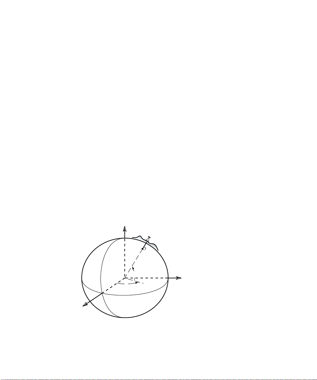
Lat, Lng, Ht
Geodetic horizontal coordinates are usually expressed as two angles
called latitude and longitude (φ, λ). Geodetic vertical coordinates are
usually expressed as the distance above the ellipsoid called height.
The angles describe a point’s position on the surface of the reference
ellipsoid. The height describes the altitude normal to the surface of
the reference ellipsoid.
X
c
h
M
e
r
i
d
i
a
n
Z
G
r
e
e
n
w
i
h
φ
λ
r
o
t
a
u
q
E
Y
8
Fig. 1: Ellipsoidal Geodetic
Coordinates
Page 13
GPS Coordinates
•
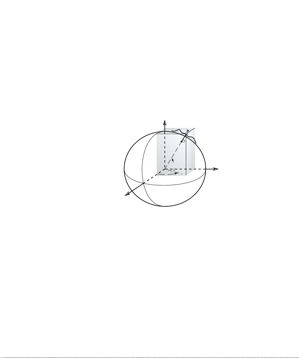
ECEF XYZ
Geodetic coordinates are some times given in the Earth Centered
Earth Fixed (ECEF) Cartesian coordinate system. This coordinate
system has its origin at the Earth’s center of mass, the primary (Z)
axis is the earth’s spin axis; the secondary (X) axis is the intersection
of the equatorial plane an d the mean meridian of Greenwich; the
tertiary (Y) axis is orthogonal in a right handed system. An ECEF
XYZ coordinate can be converted into the corresponding lat, lng, ht
using standard formulas.
i
c
h
M
e
r
i
d
i
a
n
X
Z
y
G
r
e
e
n
w
λ
a
u
q
E
x
h
z
φ
r
o
t
Y
Fig. 2: Earth Centered Earth
Fixed Geodetic Coordinates
For many surveying applications, the horizontal and vertical
coordinate systems are separate. Below are descriptions of common
horizontal and vertical coordinate systems used in surveying and
mapping.
9
Page 14

GPS User’s Manual
Horizontal Coordinate Systems
Survey projects use horizontal coordi nates on either a local plane or a
map projection. For small projects, you can assume a simple flat
earth plane and calculate coordinates directly with measured
distances. Use TDS localization mode for this procedure. For large
projects, a mapping plane is used to accurately represent the curved
surface of the earth on a flat plane and conventionally measured
distances need to be scaled to the mapping plane grid.
Map Projections
A map projection uses equations to transform local lat itude and
longitude into (y,x) Cartesian coordinates on a flat plane. Map
projections attempt to minimize distortions to the following
properties
•
A map projection is conformal when local angles are preserved.
Conformal maps are important for surveying because, for second
order surveys, angles measured on the ground are angles on the map.
Meridians (lines of longitude) and parallels (lines of latitude)
intersect at right angles and shape is preserved locally. The physical
characteristic of conformality is that the scale factor at any point on
the map is the same in all directions.
5
:
Conformality
•
Distance
A map projection is equidistant when it correctly plots distances from
the center of the projection to any other place on the map. Most map
projections involve some distortion of scale. Consequently, when
converting distances measured on the ground to distances on the grid,
a scale factor must be applied.
•
Direction
A map projection is azimuthal when azimuths (angles from a point on
a line to another point) are correctly plotted in all directions.
5
http://www.colorado.edu/geography/gcraft/notes/gps/gps_f.html
10
Page 15

GPS Coordinates
•
Area
A map projection is equi-areal when it correctly plots areas over the
entire map. That is, all mapped areas have the same proportional
relationship to the areas on the Earth that they represent.
Common Conformal Map Projections in Surveying
•
Transverse Mercator
The Transverse Mercator (TM) projection results from projecting the
ellipsoid onto a cylinder tangent to a central meridian. Scale
distortion is maximum from east to west and minimum from north to
south, so the TM projection is often used to portray areas with large
north-south extent. Distortion of scale, distance, direction and area
increase away from the central meridian.
Many national grid systems are based on the TM projection. The
Universal Transverse Mercator grid system divides the world into 60
6-degree zones. About half of the U.S. states use a TM projection for
their State Plane Coordinate Systems. The British National Grid
(BNG) is a TM projection with origin at 49 degrees north lat itude and
2 degrees west longitude.
•
Oblique Mercator
The Oblique Mercator projection is similar to the Transverse
Mercator projection; the ellipsoid is projected onto a cylinder.
However, instead of the cylinder tangent to the ellipsoid along a
meridian, it is tangent to the ellipsoid along any great circle other
than the Equator or a meridian. This makes the Oblique Mercator
projection appropriate for regions centered along lines, which are
neither meridians nor parallels.
The Oblique Mercator projection is used for Alaska State Plane zone
1, which covers the panhandle.
•
Lambert Conformal Conic
The Lambert Conformal Conic projecti on results from projecting a
sphere onto a cone tangent at two (or one) parallels of longitude.
Scale distortion is maximum from north to south and minimum from
east to west, so the Lambert projection is used to map areas of large
east-west extent. Distortion of scale, distance, direction and area
increase as you move away from the standard parallels.
11
Page 16

GPS User’s Manual
Lambert projections are used for about half of the State Plane
Coordinate System zones in the USA.
•
Stereographic
The Stereographic projection results from projecting an ellipsoid onto
a plane. Directions are true from the center point and distortions in
scale, area and shape increase uniformly away from the central point.
The stereographic projection is azimuthal.
Because the scale is distorted somewhat uniformly in all directions,
stereographic map projections are a good representation of a
surveyor’s typical flat earth ground coordinate system. For this
reason, the stereographic ma p projection is used by the TDS
localization algorithm to convert (lat,lng) into local ground level
coordinates. For more information on localization, see page 35.
Scale Factors
When converting distances on a map to distances on the ground, you
must correct for two different scale distorti ons. First, the effects of
the map projection distortion must be corrected with the mapping
plane scale factor. Second, the geometric effect of your height above
the reference surface (ellipsoid height) must be corrected with the
ellipsoid scale factor. Generally, these two scale factors are
multiplied together into the combined scale factor.
Mapping Plane Scale Factor
This scale factor accounts for the distortions caused by the mapping
plane equations as they fit a curved surface onto a flat plane. It is a
function of the mapping plane equations and its exact value depends
on your location on the map. Although the scale factor is computed
with differential equations of the map projection, one can vis u alize it
in a geometric sense. Consider the following diagrams:
12
Page 17
K=1.0 K=1.0
K>1.0
Mapping Plane
d
i
o
s
p
i
l
l
E
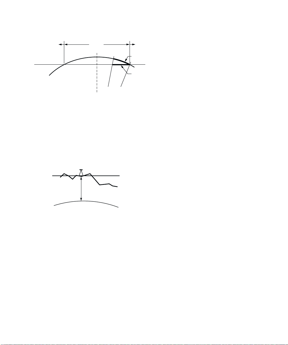
Fig. 3: Transverse Mercator Mapping Plane
K<1.0
K=0.9996
Central Meridian
K>1.0
Distance on Ellipsoid
Distance on Map
A side view of the cylinder shows the effect of scale
distortion.
•
Mapping
Plane
TDS Localization Stereographic Projection
The scale factor at the start location (usua lly the first
GPS base station in a project) is calculated for
h
Terrain
ground distances at the base height. The scale factor
increases more or less uniformly in all directions as
you move away from the base. The scale factor does
not change appreciable within the range of RTK
Ellipsoid
GPS, so this map projection is an excellent way to
model simple flat earth ground level
Fig. 4: Localization Stereographic Mapping
Plane
coordinate systems.
A side view of the ellipsoid and
stereographic mapping plane show the
scale calculated for ground distances at
the base height.
GPS Coordinates
•
Universal Transverse Mercator
Projection
The scale factor at th e central
meridian (CM) is 0.9996. The
scale factor is 1.0 approximately
170-km east and west of the CM.
The scale factor is less than one
between the CM and the point of
tangency. The scale factor is
greater than one beyond the point
of tangency. Therefore, at the
central meridian, a geodetic
distance of 100m scales into a
mapping plane distance of
99.96m.
13
Page 18
GPS User’s Manual
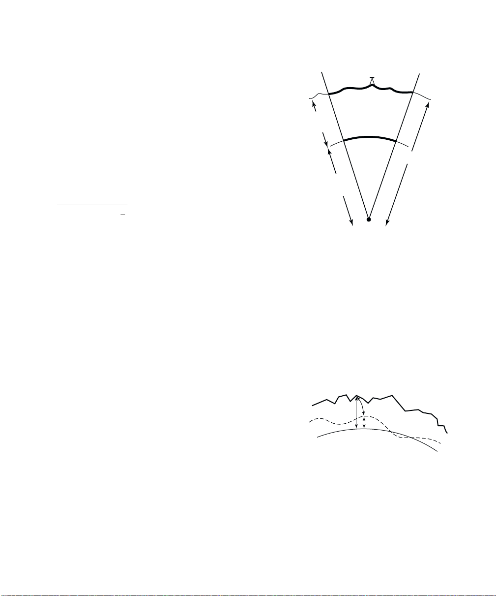
φ
Ellipsoid Scale Factor
This scale factor accounts for the height of the ground
above the reference surface (the ellipsoid). This scale
factor is defined geometrically: Consider the following
diagram:
dist
dist
k
elip
R
/(R+h) = dist
ground
/dist
elip
ground
= R/ (R+h)
=
a
e
−
/R
elip
= R/(R+h)
1
22
2
)sin1(
Ellipsoid
Height, h
Radius of
Ellipsoid, R
Fig. 5: Ellipsoid Scale Factor
Combined Scale Factor
Generally, the two scale factors are multiplied together into a
combined scale factor. The combined scale factor is then a pplied to
grid distances to get ground distances:
k
cf
dist
= k
grid
* k
elip
= dist
map
ground
* k
cf
Distance on
Ground
Distance on
Ellipsoid
R+h
Vertical Coordinate Systems
GPS measurements provide ellipsoid heights. Most
survey projects require orthometric elevations. To
convert heights into elevations, you need to correct
for the difference between the surface of the
reference ellipsoid and the level surface representing
the gravity field.
The procedure to convert heights (h) to elevations (H)
involves the use of a geoid model. The geoid is a
theoretical surface that approximates mean sea
level. If one knows the separation between the reference ellipsoid
and the geoid, called the geoid undulation (N), then one can
determine orthometric elevations from ellipsoidal heights.
14
Terrain
Geoid
Ellipsoid
H
h
N
h=H+N
Fig. 6: The Height Equation
Page 19

GPS Coordinates
Geoid Models in TDS Software
Survey Pro has several geoid models in the coordinate syst em
database. All of the geoid models use data files in geoid grid file
(*.GGF) format.
Note: To use a geoid model, geoid data files (*.GGF) must be in t he
Geodata directory.
• Users in the U.S.A., Mexico, and the Caribbean can use either the
NGS Geoid96 or the NGS Geoid99 models. This coverage
includes the continental United States, Alaska, Hawaii, Mexico,
and the Caribbean.
• Users in Canada can use the Geodetic Survey Division CGG2000
model. See the GSD web site for available data sets.
• Users anywhere in the world can use the NIMA worldwide 15-
minute geoid height grid data file, WW15mGH.ggf. This file
covers the entire globe on a 15’ x 15’ grid.
• Users in Australia can use the AUSGEOID98 data set. This data
set is available in several overlapping sub grid files in the *.GGF
format at the TDS web site.
Note: To use any of these geoids with Survey Pro, you need to
convert the files from their native format into the *.GGF format. This
is done with the Geoid Sub Grid function in survey Link. T h e
required NGS and the NIMA geoid model data files are supplied free
of charge on the TDS Survey Works CD. The Canadian GSD geoid
models are a licensed data set, so you have to contact Natural
Resources Canada to obtain the data in the NGS.bin format to use
with the Survey Link Geoid Sub Grid extraction utility. The
Australian geoid model is available in *.GGF format for download at
the TDS web site on the GPS page.6
6
Go to www.tdsway.com and select Downloads.
15
Page 20

GPS User’s Manual
Survey Pro Coordinate System
Database
Survey Pro uses a Coordinate System Database file (*.CSD) to store
the map projection and datum transformation parameters for many
different coordinate systems around the world. Also, horizontal and
vertical localization adjustments are stored as site records in the
database. Below is a list of the terminology used to describe the
different records in the coordinate system database.
• Zone: Is the basic record type. A zone record specifies the type of
map projection and its parameters. Most zone records have
datum and ellipsoid records, and usually a geoid record, already
in the database.
• Site: Is a zone record with a horizontal and/or vertical
localization adjustment added. Localizations are usually used to
correct GPS positions starting from an autonomous base. They
can be computed from control points or from manual input of
parameters.
• Zone Group: Is a collection of zone and/or site records used to
keep the database organized and user selection easier.
• Datum: Is a type of datum transformation and its parameters. A
datum record will always have an ellipsoid record already in the
database.
• Ellipsoid: Are the two parameters specifying the ellipsoid of the
datum.
• Geoid: Is a geoid model and its associated data file.
16
Page 21

GPS Measurements
This section gives a brief explanation of GPS measurements. First, a
discussion of the basic theory of differential positioning will
familiarize you with different solution types and their expected
precision. Next, step-by-step instructions will describe how to
configure Survey Pro with GPS receivers to perform either Real Time
Kinematic (RTK) GPS or data collection for post processing
differential GPS.
Pseudo-Range Positioning
GPS solutions are computed using pseudo-range positioning: Position
is determined from multiple pseudo-range measurements to different
satellites (or space vehicles SV) at a single measurement epoch. The
position of the GPS receiver antenna is computed by intersecting the
pseudo-ranges from the known SV position in a manner similar to
survey resection. Four SVs are required to determine three position
dimensions and time. Posit ion dimensions are computed by the
receiver in Earth-Centered, Earth-Fixed X, Y, Z (ECEF XYZ)
coordinates.
A pseudo-range solution will be one of two types: autonomous, or
differential. A single GPS receiver can compute an autonomous
position from ranges to four or more SV. This single receiver position
is extremely coarse. One can expect errors in the order of 100-m on a
bad day. For this reason, any precise GPS must be performed using
differential positioning.
Differential GPS
Differential GPS (DGPS) positioning involves subtracting a
combination of ranges measured to various satellites from multiple
receivers. When the signals are subtracted, the major error sources
cancel each other out. However, becaus e you are computing a
difference in ranges, the DGPS measurement solves for a coordinate
difference and not a coordinate. To compute a coordinate using a
coordinate difference, you must specify a starting point.
17
Page 22

GPS User’s Manual
Differential Solutions: Types and Quality
Code Differential
Code differential solutions use the Coarse Acquisition (C/A)
navigation code transmitted on the GPS carrier wave. Because the
wavelength of the code segment is long (300m), code differential is the
least precise differential solution. Accuracies of 1-10 meters are
possible with DGPS using C/A code differential positioning.
Carrier Phase Differential
Highly precise coordinate differences can be measured using pseudorange positioning with the carrier signal wave. Because t h e
wavelength of the carrier wave is only 19 cm, mm level positioning is
possible. When the signal arrives at the antenna, we can measure
the fractional part of the ca rrier wave. If we can then calculate the
whole number of wavelengths between the SV and the antenna (the
ambiguity), we can add it to the fractional part and multiply by the
length of one cycle to measure a precise range.
Calculating the exact number of wavelengths uses a complicated least
squares process, which is often called ambiguity resolution. The
ambiguity resolution will yield either a float or a fixed solution.
•
Fixed Solution
We know the number of wavelengths will be a whole number.
Techniques are used to constrain the least squares solution to yield a
whole number. If we get an acceptable solution, we say that this
solution is fixed. A fixed solution will generate coordinate differences
precise to about 15-ppm (si n gle frequency) or 5-ppm (dual frequency),
which translates into 15-mm or 5-mm over a 1-km base line.
Several things may prevent you from achieving a fixed solution: bad
multi-path, low number of satellites and bad constellation geometry,
poor radio link for corrections (RTK).
•
Float Solution
If the constraint algorithm does not produce an acceptable fixed
solution, then the ambiguity is allowed to be a decimal (float)
number. A float solution will generate coordinate differences precise
to about 100 to 500-ppm, which translates into 0.1-m to 0.5-m over a
1-km base line.
18
Page 23

GPS Measurements
Differential GPS with Survey
Pro
DGPS requires raw data measured from separate receivers to be
combined into a single range difference. For Real Time Kinematic
(RTK) data collection, the raw data can be broadcast using a radio
link or cell phones and the differential solution is solved in real time.
For Post Processing data collection, the raw data is collected in each
receiver’s internal memory and downloaded to a PC. Then, software
is used to combine the raw data and produce the differential solution.
Survey Pro supports three different modes of differential GPS data
collection: RTK, Post Processing, and Simultaneous RTK and Post
Processing data collection.
Selecting Data Collection Mode
1. Go to Settings from the Job menu.
2. On the Receiver
drop down box.
Mode
3. Tap 2..
Note: This switch controls the display of the Survey
GPS mode. In RTK mode, the Survey menu contains items to
configure a base and rover receiver for RTK data collection. When in
RTK mode with post processing turned on, you will get simultaneous
post processing data collection every time you occupy a point. In Post
Process mode, the survey menu contains items to configure a st atic or
a stop and go receiver for post processing data collection.
card, select
RTK
or
Post Process
in the
menu when in
GPS
19
Page 24

GPS User’s Manual
RTK Settings
If you are using Survey Pro for RTK, or RTK and post processing
simultaneous data collection, the following cards of the Job, Settings
screen contain settings specific to RTK:
• Measure Mode
occupations and the type of GPS raw data to store for each point.
You can also specify measurement acceptance criteria. For more
information see the Reference Manual.
• Projection
projection type and specify the path to geodetic data files. For
more information see the Reference Manual.
: is where you select the receiver dynamic for point
: is where you set your horizontal and vertical
Post Processing Settings
If you are using Survey Pro for post processing data collection, the
following settings apply.
• Post Process
by specifying a recording interval for the receiver’s internal
memory. You can also specify how to deal with a utonomous
positions and select a special layer to store autonomous points on.
For more information see the Reference Manual.
: is where you turn on post processing data collection
20
Page 25

RTK Data Collection
RTK data collection uses differential GPS corrections broadcast by a
base receiver to solve for coordinates at a rover receiver in real time.
This section describes how to use Survey Pro for RTK GPS data
collection. Topics include:
How to select a projection method
¾
How to configure the base and rover hardware
¾
How to set a base point in the Survey Pro software
¾
How to collect control points and solve the horizontal and
¾
vertical projections
How to collect data and stake out measurements
¾
Setting Projection Mode
When you open a new job in Survey Pro, the
Ground - TDS Localization
ground coordinates in any arbitrary coordinate system, such as a
resurvey of an old job or a brand new job from a single start point.
Using
datum or map projection. Survey Pro will automatically initialize a
default projection for ground level dist ances when you configure the
first RTK base station in the job.
If your job requires a specified map projection and datum from the
coordinate system database, then you should switch
to
projection zone from the database or creates a custom zone and
datum transformation using Survey Pro.
In either horizontal projection mode, the user can choose one of two
methods for vertical projection:
Heights
vertical coordinate to be orthometric elevations.
to use the GPS measured height as the local vertical coordi nate.
Ground - TDS Localization
Mapping Plane
. Use
. In
Localization (+Geoid)
. This is the default mode to produce
, the user does not need to select a
Mapping Plane
mode the user selects a map
Localization (+Geoid)
mode when you want the local
Projection Mode
Projection Mode
, or
Use Ellipsoid Heights
is set to
Ellipsoid
21
Page 26

GPS User’s Manual
Projection Mode Summary
Horizontal
Ground - TDS Localization
• Local coordinates are at ground level, based on the project height.
• Distances shot with EDM are at ground scale, so are 1:1 with
coordinates solved by the projection.
• Default map projection and datum are automatically initialized
with RTK base setup.
Mapping Plane
• Local coordinates are on a conformal map projection grid.
• Distances shot wi th EDM are usually scaled by the combined
scale factor to distances on the map projection grid.
• User selects map projection zone.
Vertical
Localization (+Geoid)
• Vertical coordinate is orthometric elevation.
• User must solve transformation from ellipsoid heights to
elevations. This is done with Localization on control points, or
using a geoid model, or a combination of both.
Ellipsoid Heights
• Vertical coordinate is ellipsoid height.
• This mode requires no transformation setup. Use this mode when
vertical coordinates do not need to be elevations.
If you are using
projection mode, and you are not using a geoid model, Survey Pro is
ready to start the RTK survey upon opening the new job. No
projection setup is necessary, so you should move ahead to the next
section on Configuring Receivers.
22
Ground- TDS Localization
for your horizontal
Page 27
RTK Data Collection
Note: If you are using
projection mode, and you want to use a geoid, you only need to select
the geoid model once. Survey Pro remembers the geoid model you
last used and will automatically assign this geoid in a new job's
Localization map projection zone. You can go directly to Receiver
Setup after opening a job.
If you are using a map projection zone and/ or you want to use a geoid,
but have never selected one, you will need to choose a zone and/or
geoid record from the user interface. The following section describes
how to select a map projection and geoid model from the coordinate
system database.
1. Go to Projection
at the top of the screen to open the Projection card of the Settings
screen. Select the appropriate Horizontal and Vertical Projection
Mode and tap OK.
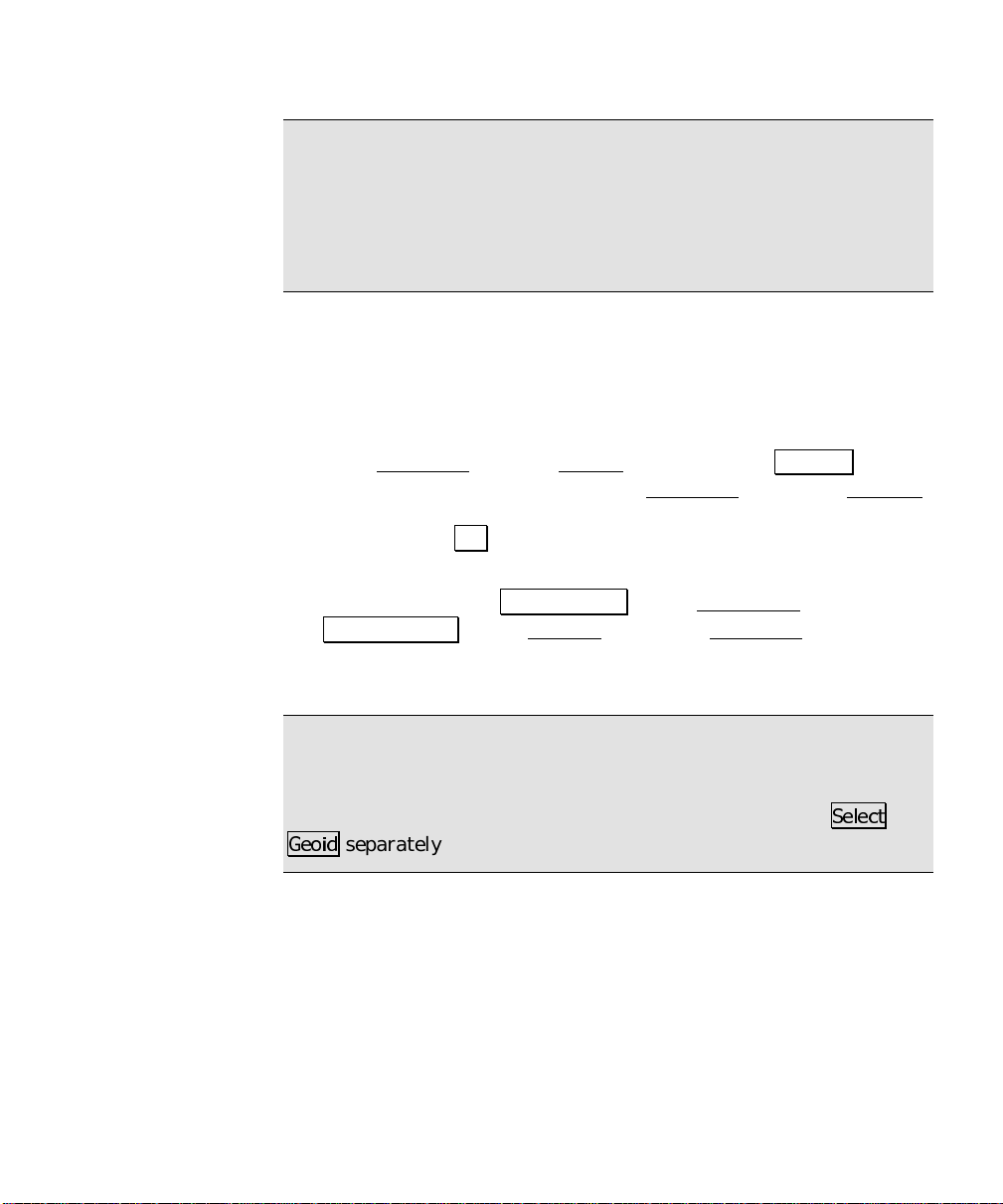
2. If you selected either
them up now. Tap Select Zone… on the Horizontal
Select Geoid… on the Vertical card of the Projection screen. You
can also wait and you will be automatically prompted to set them
before the first operation th at requires these settings.
Ground- TDS Localization
from the Survey menu. Tap the Settings button
Mapping Plane
or
for your horizontal
Geoid Model
, you can set
card and
Note: In Mapping Plane mode, when you select a zone record from
the coordinate system database, it may have a geoid model attached.
If the selected record has a geoid model attached, this record will
become the geoid for the job file and you do not need to tap
*HRLG
separately.
6HOHFW
23
Page 28
GPS User’s Manual
Mapping Plane Setup
Use the Mapping Plane Setup screen to either select a map projection
zone from one of the zone groups, or select a local ized map projection
site from the database. This screen is also used to open the Projection
Key In Setup wizard where you can key in the parameters of a
custom map projection and datum.
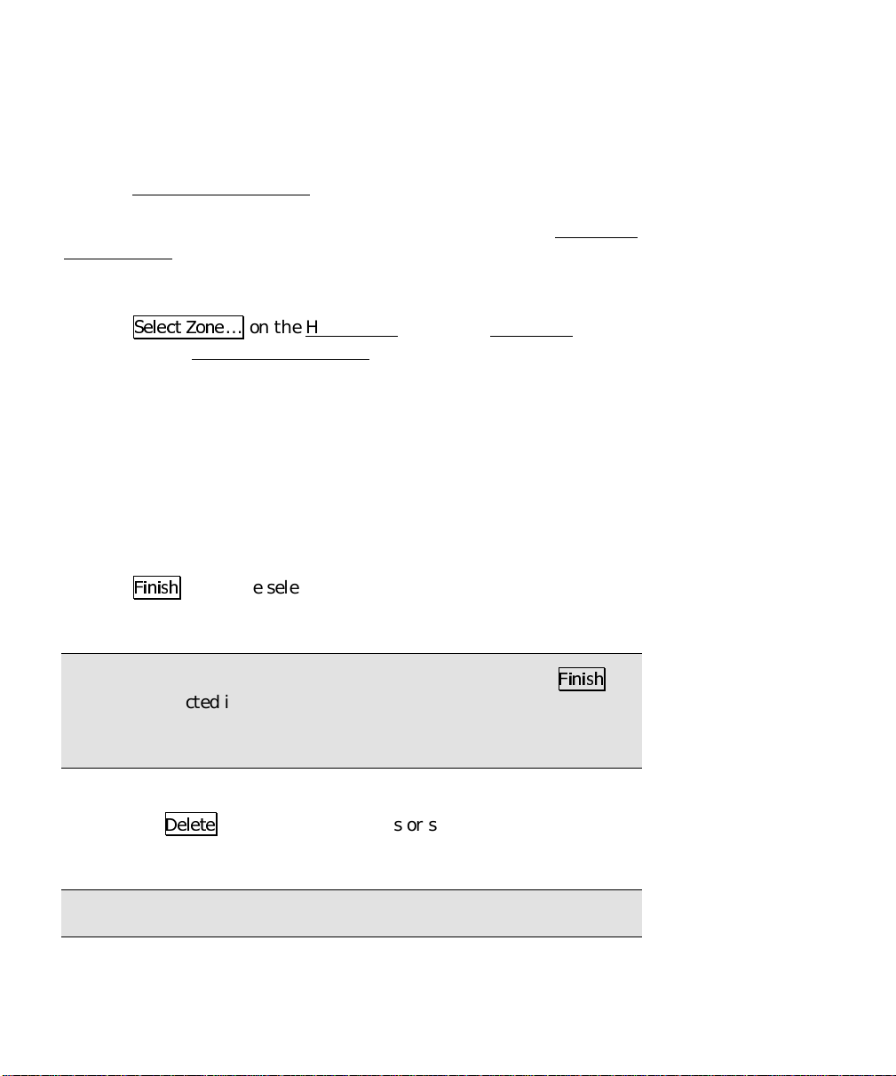
1. Tap
2. To pick a map projection zone from the database, tap
3. If you are picking a map projection z one, select the
4. Select the
5. If you have selected a zone with a datum and a geoid model
6. Tap
6HOHFW =RQH
to open the Mapping Plane Setup screen.
in the
Data Base
the database, tap
from the drop down list.
attached, the datum and geoid name will be displayed. If you
have selected a UTM zone, you must select a
down list.
)LQLVK
record.
… on the Horizontal
box. To pick a localized map project ion site from
View Sites
or
Zone
to set the selected zone or site as the current projection
Site
in the box.
from the drop down list.
card of the Projection screen
View Zones
Zone Group
from the drop
Datum
Note: When you select a zone with no datum, after you tap
the datum selected in the drop down list will be added to a copy of the
selected zone record and you will be prompted to save the new zone
record with a unique name.
• Use the
You can only delete user created sites, you cannot delete the
original 'system' records in the database.
Note: You cannot undo the deletion of a zone.
24
'HOHWH
button to delete zones or sites from the database.
)LQLVK
,
Page 29

RTK Data Collection
• Use the Key In Parameters button to open the Projection Key In
Setup screen where you can configure a custom map projection
and datum.
Projection Key In Setup
Use the Projection Key In Setup screen to create a custom map
projection and a custom datum transformation to use as the selected
mapping plane zone:
1. Tap Select Zone… on the Horizontal
to open the Mapping Plane Setup screen.
2. Tap Key In Parameters > on the Mapping Plane Setup
open the Projection Key In Setup screen.
3. Pick the
zone types are:
•
•
•
•
•
4. Pick the
datum are:
5. Select the
are:
6. Select the
projection zone. Choices for grid direction a re:
Zone Type
Transverse Mercator
Lambert 1 parallel
Lambert 2 parallel
Stereographic
Oblique Mercator Angle
Datum Type
•
Pick from Data Base
from the coordinate system database.
•
Custom Molodensky
three-parameter datum transformation.
•
Custom Similarity
seven-parameter datum transformation.
Azimuth
•
North Azimuth
grid.
•
South Azimuth
Grid
for the new map projection zone. Supported
(oblique and polar)
for the new map projection zone. Choices for
. Select this choice to use a datum
. Select this choice to enter a custom
. Select this choice to enter a custom
type for the new map projection zone. Choices
. Select this choice to have a north azimuth
. This choice to have a south azimuth grid.
direction for positive coordinates in the new map
card of the Projection screen
screen to
25
Page 30
GPS User’s Manual
•
North\East Grid
increase positive in the north and east directions.
•
South\West Grid
increase positive in the south and west direct ions.
Note: The geodetic calculation engine and the Survey Pro coordinate
geometry engine are separate components. While the geodetic engine
can properly handle southwest grid systems, Survey Pro can only
operate on a northeast grid system. However, since a southwest grid
with a south azimuth is a mirror image of a northeast grid with a
north azimuth, Survey Pro can handle this configuration with the
following work around: You must set the
Azimuth
north as south and east as west, and the coordinates will be correct
for a southwest grid and south azi muth zone.
on the Units
. Select this choice to have coordinates
. Select this choice to have coordinates
Azimuth Type to North
card of the Job, Settings screen. You then treat
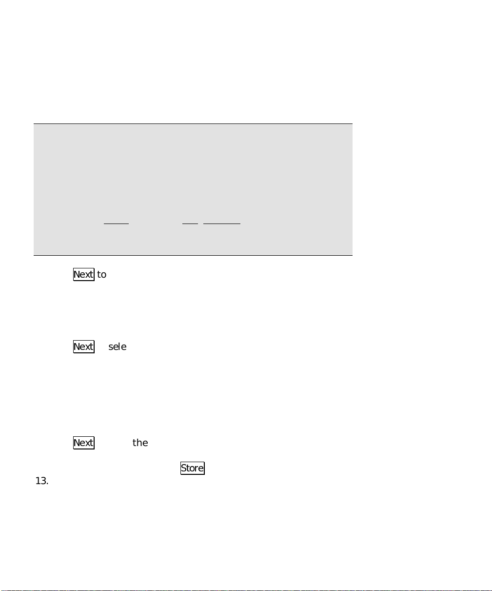
7. Tap
8. Key in the five or six paramet ers for your new map projection
9. If your zone is Oblique Mercator Angle, the next screen is used to
10. Tap
11. If you selected
12. Tap
13. If you are using a custom datum, enter the datum translations
26
1H[W
to enter the zone parameters for the new map
projection.
zone.
pick the
1H[W
on the datum type you specified on the first screen.
the list. If you selected either
Similarity
Ellipse from Data Base
database, or you can select
a custom ellipse.
1H[W
datum, the next screen displays the parameters for the new map
projection zone and you can
from WGS84 to Local.
and
Origin
to select the datum. The screen that opens will depend
, then select an ellipse for the new datum. You can select
to open the next screen. If you are using a database
Azimuth
Pick from Data Base
values.
, pick the database
Custom Molodensky
to use an ellipsoid record from the
Key In Ellipse
6WRUH
the record.
to input parameters for
or
Datum
Custom
from
Page 31

RTK Data Collection
Note: Note the sign of the datum shift and rotation parameters.
Some datum transformations are given in terms of local datum to
WGS84. Survey Pro always assumes datum transformation
parameters are WGS84 to local. You might need to reverse the sign
of the datum parameters you have to use them in Survey Pro.
14. Tap
15. If you are using a
16. Tap
1H[W
. If you are using a
screen will be the final screen where you can
Custom Similarity
from WGS84 to Local. Also enter the scale, in parts per million
from WGS84 to the local datum.
1H[W
to open the final screen where you can review the
parameters for the new map projection zone and where you can
6WRUH
the record to save it in the coordinate system database file.
Custom Molodensky
datum, enter the rotation
datum, the next
6WRUH
the record.
Selecting Geoid Model
Use the Geoid Model Setup screen to select a geoid model and data
file to use with either the localization zone or the selected map
projection zone. This screen is also used to remove the geoid from the
current projection record.
1. Tap Select Geoid… on the Vertical
to open the Geoid Model Setup screen.
2. Select a
3. If there are no data files for the selected geoid model, the
control will display "No .ggf files for this geoid." If there is only
one data file for the selected geoid, the
that .GGF file name. If there are multiple data files for the
selected geoid, select the geoid you wish to use from the list.
When there is a geoid file displayed, the
displays the data file name from the .GGF file header.
4. Tap Accept to set the geoid for the current projection record
and/or change the data file used by the current geoid model.
• Use the Remove Geoid From Zone button to remove the geoid
model from the current projection record.
Geoid Model
to use from the list.
card of the Projection screen
File
control will display
File
File Name
control
27
Page 32

GPS User’s Manual
Using Ellipsoid Heights
Ellipsoid height is a method that stores the local ellipsoid height
measurement as the vertical coordinate. Use ellipsoid heights if the
vertical is not important to the project, or when you intend to
transform heights to eleva tions in the office using a s eparate
program.
1. Set the
card to
2. Tap 2.. Using vertical ellipsoid heights requires no additional
projection solution.
Vertical Projection Mode
Ellipsoid Height.
on the Job
, Settings, Projection
Receiver Setup
General Hardware Configuration
1. Connect the power cable or insert
the internal battery in to the GPS
receiver.
2. Connect the antenna cable.
3. Plug the data collector serial
cable into a receiver comm. port.
4. If your receiver does not have an
internal radio, plug the radio
serial cable into a receiver comm.
port. An external radio may need
its own power supply. If the radio
comm. port does not supply
power, plug the radio into
external power.
5. Turn the receiver power on.
+-
Battery
Radio
Data Collector
Some systems do not require an external battery.
The baud rates can be different on each serial port.
Fig. 7: General Hardware Configuration
Power
Serial
Serial
GPS Antenna
Receiver
GPS Antenna
28
Page 33

6. Plug the data collector into the receiver.
RTK Data Collection
7. Go to the Receiver
5HFHLYHU 6HWWLQJV
Data Collector to Receiver Communications
8. We will automatically attempt to connect to the receiver. If we
can not connect to the receiver, you will be prompted to auto
detect the correct baud rate and receiver port. Tap 2. at the
prompt or tap
9. If the port and baud rate detected are not appropriate for your
receiver, correct them now. If this is not the correct port, then
plug the serial cable into the correct port on the receiver and redo
$XWR 'HWHFW
baud and tap
10. Communications is now set. Tap
Format for RTK Corrections
11. Select your
the combo box.
Receiver to Radio Communications
12. Select the type of radio modem you are using.
. If this is not the correct baud, then select the correct
Format for RTK Corrections
card from the Job, Settings screen. Tap
.
&KDQJH
5HFHLYHU 6HW
and then
.
$XWR 'HWHFW
2.
on the Receiver card.
from one of the choices in
13. Make sure the baud; parity; and port is correct for the radio. On
the Base/Rover Radio
correct, tap
14. Depending on your modem type selected, you may be able to
configure certain parameters of the modem using Survey Pro.
Tap the
screen.
General Settings
15. Set the elevation cutoff. On the General
cutoff to be used when you configure the receiver.
&RQILJXUH 6HULDO
&RQILJXUH 0RGHP
card, verify the settings. If settings are not
and set the correct values.
button to open the Radio Settings
card, select the elevation
29
Page 34

GPS User’s Manual
16. Set any other parameters specific to your brand and model. On
the General
available.
17. Hardware configuration is complete. Tap 2. twice to return to
the Base Setup screen.
RTK Configurations
Note: The following step is only necessary if you need to use
different COM port settings for your base and rover RTK receivers.
18. Set the base or rover configuration. If this receiver is the RTK
base, tap
RTK rover, tap
automatically set the switch to
configuration
Survey menu, the correct COM port and settings will be set
automatically.
card, different receiver brands have special settings
6DYH FXUUHQW UHFHLYHU DV 57. %DVH
6DYH FXUUHQW FRQILJXUDWLRQ DV 57. 5RYHU
Auto Connect RTK with saved
. When you tap
6HW %DVH
. If this receiver is the
or
6HW 5RYHU
from the RTK
. This will
Base Station Receiver Setup
Use the Base Setup screen to configure a GPS receiver to be an RTK
base station and to set the base reference position in Survey Pro.
1. Tap
Pick the Base Point
2. Tap
30
%DVH 6HWXS
Base screen where information about the current setup is
displayed. Tap
6HWXS +5
or vertical height of the antenna.
on the Survey
6HWXS
… to start the Base Setup
to select your antenna type and measure the slant
menu to open the Current GPS
wizard.
Page 35

RTK Data Collection
Note: If this receiver has already set an antenna with Survey Pro,
the measurement and settings will be recalled from the registry, so
you will not have to do this step again.
3. Enter a name for the
from the job or you can enter a new point name for the job. If you
select:
• An existing point with geodetic coordinates, we send t hese
reference coordinates to the GPS receiver and configure the
base coordinate in Survey P ro.
• An existing point with plane only (N,E,Elev) coordinates , we
calculate geodetic coordinates from the current projection,
then send this reference position to the GPS receiver and
configure the base coordinate in Survey Pro.
• A new point, or, an existing plane point when no projection is
solved, we start from an autonomous position. You will GET
an autonomous position from the GPS receiver for your first
base setup. You then SET this reference position in the GPS
receiver and configure the base coordinate in Survey Pro.
Note: It is strongly recommended that you use only one autonomous
GPS base position in a job. If you must use multiple autonomous
setups in a single job, you will be prompted to setup and select a
separate site record for each setup group.
4. Tap
1H[W
.
Base Point
. You can select an existing point
Set the Base
The final step of the Base Setup
chosen. If the base (lat, lng, ht) is known or can be computed, the
final step is to SET the base at the known geodetic position. If the
base (lat, lng, ht) is not known, the final step is to GET an
autonomous position to SET the base with.
wizard will depend on the base point
31
Page 36

GPS User’s Manual
SET Base at Known Geodetic Coordinate
5. Tap
Note: If you have post processing data collection turned on, the
receiver will now open a file (with the next available default name),
start recording GPS raw data, and enter the station and antenna
information for this setup.
6. When done, you will return to the Current GPS Base screen
7. Tap
GET Autonomous Base Position
If you are starting from a new point i n the job, you can GET an
autonomous GPS position from the receiver to SET the base reference
position and configure the base coordinate in Survey Pro.
8. Tap
9. Check the results displayed in the edit boxes. If it looks good, tap
6(7
to configure the base receiver with this position and
begin broadcasting RTK corrections over the radio link.
where the base stat ion details are displayed.
&ORVH
to return to the Survey
*(7 3RVLWLRQ )URP 5[
receiver. If you wish to get an averaged position, enter a number
in
Average position [n] epochs before GET
6(7
to configure the base receiver with this position and begin
broadcasting RTK correcti ons over the radio link.
to get an autonomous position from the
menu.
.
Note: If you have post processing data collection turned on, the
receiver will now open a file (with the next available default name),
start recording GPS raw data, and enter the station and antenna
information for this setup.
32
Page 37

RTK Data Collection
Rover Receiver Setup
Use the Rover Setup screen to configure a GPS receiver to be an RTK
rover.
1. Go to Rover Setup
Rover setup procedure depends on how the base was set. If the base
was set with this data collector, the base reference position is already
known in Survey Pro and you can simply SET the rover to start your
survey. If the base was set with a different data collector, you need to
GET the base reference position from the radio link to configure the
base coordinate in Survey Pro and start your RTK survey.
SET Rover with Known Base Position
2. Tap
Note: If this receiver has already set an antenna with Survey Pro,
the measurement and settings will be recalled from the registry, so
you will not have to do this step again.
3. Tap
Note: If you have post processing data collection turned on, the
receiver will now open a file (with the next available default name),
start recording GPS raw data, and enter the antenna information for
this setup.
6HWXS +5
or vertical height of the antenna.
6(7 5RYHU
base information over the radio link.
from the Survey menu.
to select your antenna type and measure the slant
to configure the receiver and begin receiving RTK
4. You will return to the Survey menu when this is complete.
GET Base Position from Radio Link
a. Tap
b. Tap
6HWXS +5
or vertical height of the antenna.
*(7 IURP %DVH
RTK base information over the radio link.
to select your antenna type and measure the slant
to configure the receiver and begin receiving
33
Page 38

GPS User’s Manual
c. Note: If you have post processing data collection turned on, the
receiver will now open a file (with the next available default
name), start recording GPS raw data, and enter the antenna
information for this setup.
d. Once the base station location is received over the radio link, you
are prompted to set the base reference position is Survey Pro. If
the base coordinate already exists in your job file, then that point
is chosen by Survey Pro as the base point. If the coordinate is new
to the job file, then you are prompted to give this new point a
name and Survey Pro will create the new base point.
e. The Base Setup
displayed.
f. If your receiver does not support antenna height configuration,
Survey Pro will attempt to calculate the height. You must verify
that the values are correct.
g. Tap
h. When done, you will return to the Survey
1H[W!
displayed. Tap
position in Survey Pro.
wizard opens with the chosen
and the base position received from the radio link is
6(7
to configure the base station reference
Base Point
menu.
name
Solve Localization
When you start a GPS survey from an autonomous base position, you
need to solve a Localization to adjust GPS measurements into local
coordinates. This is the case for both horizontal projecti on modes.
Using
Ground - TDS Localization
relate your arbitrary GPS start point into your non-geodetic local
system. Using a
shift the autonomous GPS start point into accurate geodetic
coordinates.
In either horizontal mode, the procedure is the same. Starting from
an autonomous GPS base setup, you measure GPS positions on
control points with know local plane (N,E) coordinates. The
parameters for a 2D similarity transformation are calculated with a
Mapping Plane
, you need to solve a localization to
, you need to solve a localization to
34
Page 39

RTK Data Collection
least squares solution using the control points. These parameters are
added to the zone record (selected map plane zone or defa ult
Localization zone) to create a zone based site record.
Vertical Localizations, with or without a geoid model, uses the same
field procedure. Starting from an au tonomous GPS base setup, you
measure GPS positions on control points with know l ocal elevations.
The vertical adjustment parameters are calculated from the control
points. The vertical adjustment will be either a shift to correct geoid
elevations to local elevations, or an inclined plane to correct for
vertical shift and tilts.
Note: If you are starting a new job in
mode, you do not need control points. Simply set the base on your
first job file point and solve the projection at the prompt. For a more
detailed description of the easiest way to start a new job using Survey
Pro, see the section on One P oint Localizations . See Page 46.
Ground - TDS Localization
Localization with Control Points
Horizontal localization is a simple 2D similarity transformation from
mapping plane coordinates in an intermediate system to coordinates
in your local system. In
intermediate system is the default map projection initialized for
ground distances at the base height. In
intermediate system is the inaccurate map projection calculat ed from
the autonomous GPS base.
Vertical localization is a correction from measured ellipsoid heights or
geoid elevations calculated from heights, into local elevations. This
correction can be a simple shift or a three-parameter inclined plane.
Localization with Control Points: Summary
Select horizontal and vertical projection methods on the
¾
Projection
Configure the hardware and set up the base and rover
¾
receivers.
card of the Job, Settings screen.
Ground - TDS Localization
Mapping Plane
mode, the
mode, the
35
Page 40

GPS User’s Manual
Take GPS measurements to a minimum of two horizontal
¾
control points, and either one vertical control point (to
calculate shift for geoid model) or three vertical control points
(to calculate an inclined plane).
Go to Projection
¾
/RFDOL]DWLRQ «
Select the points to use for horizontal and vertical control and
¾
tap
6ROYH!
.
from the Survey menu. Tap
6ROYH
Verify solution residual or misclosure quality. Tap
¾
review the parameters and tap
Occupy additional local points as check points to verify
¾
solution quality. If desired, additional points can be added as
control points and included in solution.
Note: When you resolve the localization, all of your GPS measured
points will automatically be recalculated based on the latest solution.
Therefore, your local coordinates derived from GPS measurements
will always be calculated using the latest solution.
Detailed Procedure
Since the field procedure is the same for both horizontal and vertica l
localization solutions, the instructions below cover both cases.
1. After choosing the projection settings (see page 21) and
configuring the base and rover receivers (see page 24), go to
Control Points
2. Select a control point to occupy and enter the name into the
control. Horizontal control points must have a valid northing and
easting coordinate in the local system. Vertical control points
may have a valid horizontal coordinate (although it is not used in
the calculation) but must have a valid elevation.
from the Survey menu.
$FFHSW
to finish setup.
1H[W!
to
Point
36
Page 41

RTK Data Collection
Note: If you select a point from the job’s control file, you will be
prompted to make a local copy of the point. Control point collection
will add a geodetic coordinate to the point record and points in the
job’s control file cannot be modified.
Note: If
Store GPS Raw
Settings screen is set to
Data on the Measure Mode
EP + Rx Raw
(or + OBN for Ashtech users),
card of the Job,
when you begin a point occupation the control point name is checked
as a valid site ID for the receiver. If it is not a valid site ID, we will
use a modified point name in th e receiver’s internal file and make a
note of the modified name in the job’s .RAW file. The point name in
Survey Pro is not changed.
3. Occupy the point and tap
4. When you are happy with the measurement, tap
&RQWURO 3RLQW
to begin data collection.
$FFHSW
.
5. Check the Results tab for details of th e previous measurement.
Check the Map
tab to see the number and position of control
points for this set up group.
6. Collect a minimum of 2 control points to solve horizontal
localization. Collect a minimum of three vertical control points to
solve vertical localization. Collect one vertical control point to
solve just the localization vertical shift when using a geoid model.
7. When you have collected the minimum number of control points,
tap
3URMHFWLRQ
to open the Projection
screen.
37
Page 42

GPS User’s Manual
8. Tap
Note: If you are using localization for the vertical transform mode,
then the next screen will look like the illustration below. If you are
using ellipsoid heights, then the vertical column will be missing.
9. In the list box, control points collected
Note: If your base was set up on a known point, that point is an
eligible control point. If your base was set up on a new point, then it
is not visible on the control point list.
6ROYH /RFDOL]DWLRQ
will be identified with an H and/or V.
Points marked H will be used to solve
horizontal localization. Points marked
with a V will be used to solve vertical
localization. You can select or deselect
any point by highlig hting that point and
then: tap the H and/or V column beside
that point; press H and/or V on the
keyboard.
to open the Solve Localization
wizard.
10. If you wish to hold the scale of the GPS measurements, but you
want the localization adjustment to correct for a rotation, check
the
Solve Rotation Only
11. Double check the selection of control points and tap
localization parameters are computed using the selected control
points, and the next screen is opened with solution RMS values.
12. For both horizontal and vertical, the solution type and RMS value
from the control points are displayed. The solution type will be
one of:
38
control in the
Fix H Scale to 1.0
6ROYH !
box.
. The
Page 43

RTK Data Collection
•
Unique
using less than the minimum number
of control points (1 horizontal or 2
vertical). In this case, there is no least
squares solution so the numbers in the
N Err, E Err
misclosures calculated from the
control points not used in the solution.
: the solution was calculated
, and/or
columns are
V Err
•
and/or
solution.
13. If you are not happy with the solution residual or misclosure
values for any point, you can change the control points used by
tapping in the H and/or V columns. This will change the
button to a
the solution and update the residual / misclosure display.
14. When you are happy with the solution quality, tap
review the parameters.
15. Examine the scale and rotation values to verify they are
reasonable. See the expla n ation of localization parameters (page
48) to determine what is reasonable.
16. When you are happy with the solution, tap
horizontal and/or vertical adjustment. If this is the first
localization solved, you will be prompted to name the site record.
If you are resolving a localization, the parameters of the existing
site will be updated.
columns show residuals for each point used in the
V Err
6ROYH!
button. Tap the
: the solution was calculated with
LSQ
at least the minimum number of
control points (2+ horizontal and/or 3+
vertical). In this case the
6ROYH!
button to recalculate
$FFHSW
N Err, E Err
1H[W!
1H[W!
to
to set the
,
17. Tap
&ORVH
to return to the Control Points
screen.
39
Page 44

GPS User’s Manual
Manual Entry of Parameters
Manual entry of parameters is used when you already know the
appropriate horizontal and vertical localization parameters for a site.
Use manual entry of parameters to key in the site parameters and set
it as the current projection record.
If you already know the scale, rotation, translation, and origin for a
horizontal site, or if you know the slope, shift and origin of a vertical
site, you can manually set the localization parameters.
1. After receiver setup, go to Projection
2. Tap
3. Enter the
4. Enter the
5. Tap
6. Review the results and tap
40
6ROYH /RFDOL]DWLRQ
then tap
horizontal system.
adjustment.
entered.
0DQXDO (QWU\!
Scale, Rotation, Translations
Slope N, Slope E, Separation
6ROYH!
to show the horizontal and vertical parameters
to open the Solve Localization
.
$FFHSW
when you are done.
from the Survey menu.
wizard and
, and
, and
of the
Origin
of the vertical
Origin
Page 45

RTK Data Collection
Localization Parameters Explained
Before you accept a localization solution, you should evaluate the
parameters and the quality of the solution. This section describes the
meaning and the expected values for the six horizontal and five
vertical localization parameters. Guidelines for the quality and
geometry of control points plus the solution redundancy and residuals
are also described.
Ground - TDS Localization Mode:
Scale: is the scale difference between the
intermediate mapping plane and the local
system. Scale s h ould be very close to 1.0. A
value of 1.0 corresponds to ground level
distances at the base reference height.
Scale values are often reduced to parts per
million in order to relate the factor to a
distance. One ppm (the sixth decimal place ie.
1.000001 or 0.999999) is equal to 1mm in
1km; this is well below RTK precision.
Fifteen ppm (1.000015 or 0.0.999985) is equal
to 15mm in 1km; this is a usual RTK
precision, so anything in this range is expected. A scale value
significantly greater or smaller than 1.0 may indicate problems with
the control point accuracy and/or the control measurement precision.
It might also indicat e a base reference height too high or low for the
survey area, or a scale bias in the control point local coordinates.
Rotation: is the rotation between the Localization map projection
zone and the local system. The rotation represents th e difference
between grid north and geodetic north at the meridian passing
through the origin of the Localization transformation.
Origin: is the coordinate on the intermediate mapping plane of the
centroid of the control points. It is calculated by average of (N, E)
coordinate of all control points.
Translation: is the shift between the origin and the local coordinate
of the centroid of the control points
41
Page 46

GPS User’s Manual
Mapping Plane Mode:
Scale: is the scale difference between t h e intermediate mapping
plane using the autonomous GPS position and the actual mapping
plane control coordinates. Scale should be very close to 1.0. A value
of 1.0 corresponds to grid distances on the selected conformal
mapping plane.
A scale value significantly greater or smaller than 1.0 may indicate
problems with the control point accuracy and/or the control
measurement precision. It might also indicate a scale bias in the
control point plane coordinates, which you may want to correct by
solving a fixed scale transformation.
Rotation: will be 0.0 for Localized map projections.
Origin: is the coordinate on the intermediate mapping plane of the
centroid of the control points. It is calculated by average of (N, E)
coordinate of all control points.
Translation: is the shift between the origin and the local coordinate
of the centroid of the control points. This value represents the shift
from the inaccurate autonomous GPS start point and the actual
coordinates for that position. This value should be less than 15 m
with Selective Availability turned off.
Vertical:
Slope: is the North and East tilt of the
inclined plane adjustment. These values are
given in parts per million, and represent the
radian angle values of the deflection between
the ellipsoid normal and the local gravity
vector. These values ar e also called
'deflection of the vertical'.
Separation: is the shift between the local
elevation and the vertical reference surface
(geoid elevations when using a geoid model
or ellipsoid height when using Localization vertical only).
Origin: is the local coordinate of the first point used in the control
point list. The slope values are applied from this point.
42
Page 47

RTK Data Collection
Normal to
Ellipsoid
Separation
Normal
to Geoid
Deflection (a,b)
S
d
i
o
e
G
i
o
s
p
i
l
l
E
e
c
a
f
r
u
e
c
a
f
r
u
S
d
Fig. 9: Vertical Localization
Three control points calculate a plane to model the deflection and shift
between the geoid and ellipsoid surface.
Vertical Calibration and Geoid Modeling
If you do not use a geoid model, vertical localization will solve for
slope and separation using the measured heights and the control
elevations. If you do use a geoid model, vertical localization will solve
for the separation between the geoid elevation and your control
elevation. Geoid elevations are computed from measured heights and
geoid undulation using the height equation (see page 14):
h = H + N
Quality of Localization Solution:
Starting from an autonomous GPS base position and solving a
Localization with control points is like starting a conventional survey
from an unknown setup and solving a resection. The quality of the
solution depends on both the precision of the measurements to the
control points and the accuracy of the control point coordinates.
When solving a Localization with control points, the following
guidelines should be followed:
• Quality of control points: the control point coordinates should be
at least as precise as the specified survey requirements.
43
Page 48

GPS User’s Manual
• Geometry of control points: the control points should be
distributed evenly surrounding the survey area.
Fig. 10: Good Control Point
Geometry
Three control points surround the
project area.
• Check points: after solving for localization parameters with a
minimum number of control points, you should occupy an
independent checkpoint to verify the solution quality. If you
desire, this point can be added as a control point and used for
subsequent solutions. If the checkpoint measurement is within
the tolerance, this step should not be necessary.
• Redundancy and residuals: After solving localization parameters
with more than the minimum number of control points, you
should examine the solution residuals. The residuals should be
close to the measurement precision of your instrument and the
control points.
Fig. 11: Poor Control Point
Geometry
Three control points in one corner of
the project area. Also, for vertical
localization, the three control points
are close to co-linear.
44
Page 49

RTK Data Collection
φ
Ground - TDS Localization Explained:
When the horizontal projection mode is
default map projection is automatically set up to produce ground
coordinates at the base station height. The TDS Localization map
projection is an oblique stereographic map projection with the
following parameters:
o
Origin is at the initial base station location
o
False northing and false easting of 100000.0 m
o
Scale at the origin of t h e stereographic map projection zone is
calculated to produce ground scale distances at the height of
the first GPS setup. This projection scale factor is simply the
inverse of the ellipsoid scale factor described earlier (see page
12).
Origin Scale (k
R
=
e
−
Localization Setup Groups
When you set up different base stations with autonomous positions
from a GET, each position is only accurate to +- 30m (+- 10 m with
Selective Availability (SA) turned off). Geodetic coordinates
measured from your first autonomous base will not be accurately
connected to geodetic coordinates from a different autonomous base.
Although the localization parameters will accurately transform both
sets of data to the local coordinate system, it is not possible to
compare the geodetic coordinates from the different sets of data.
map
a
22
) = (R+h)/ R
1
2
)sin1(
Ground - TDS Localization
, a
Survey Pro solves this problem by assigning a set up group each time
a new autonomous base is set. A set up group is a unique flag
attached to each point record generated by GPS. Setup groups are
assigned as follows:
When you set a new base point with an autonomous GET, Survey
•
Pro creates a new set up group for this point.
45
Page 50

GPS User’s Manual
• When you collect geodetic measurements, each new point is
assigned the set up group of the current base station.
• When you set the base on an existing point with geodetic
coordinates, the point’s existing set up group is used as the new
base station set up group.
• When you set the base on a point with existing plane coordinates
and compute geodetic coordinates using the ‘Move Base’
algorithm, the existing base station set up group is used as the
new base station set up group.
One Point Localizations
When you open a new job and you want to do a ground level survey
starting at the coordinate of the first point, you can do a one-point
localization when using
Below is a description of the easiest way to setu p a new job projection
and start a survey.
1. Open a new job and assign the desired local north, east, and
elevation to the first point.
TDS Localization
horizontal projection mode.
2. Set the GPS base receiver up on this point and GET an
autonomous position and SET the base.
3. At the projection prompt, choose
Localization screen. With your base as the one control point, tap
6ROYH!
4. Review the parameters of the solution.
• Scale factor of 1.0 means coordinates will be at ground level at the
base station height. Distances measured with an EDM at this
height will be 1:1 with GPS measured coordinates.
• Rotation of 0.0 means that the coordinate system's grid north is
equal to geodetic north at the meridian of the initial base. This is
equivalent to using a sun shot azimuth as grid bearing through
this meridian.
46
.
6ROYH 1RZ
to open the Solve
Page 51

RTK Data Collection
• Delta N and E are the translations between the desired local start
coordinate and the origin of the TDS Localization map projection
(100000, 100000) m.
5. Tap
$FFHSW
. You are now ready to start data collection.
Localization Calculator
Note: The Localization calculator is used to provide the field
procedure for a workflow supported in Survey Pro versions prior to
3.5. This routine is similar to a one-point Localization, except that
rotation is calculated parallel to a selected map projection. The
easiest way to start a ground survey is with the one point
Localization procedure described above.
1. After choosing the projection settings and configuring the base
and rover receivers, go to Projection
2. Tap
Note: The vertical card will be the vertical manual parameter screen
described in the previous section.
6ROYH /RFDOL]DWLRQ«
then tap
&DOFXODWRU!
to open the Solve Localization wizard and
.
from the Survey menu
3. Leave the scale at 1.0. For an explanation of the scale factor or to
review the reference height used for ground scale, tap the
6FDOH
button.
4. Calculate the rotation for this setup. Tap
the Localization Calculator. If you have not already selected a
mapping plane, you will be prompted to do so now.
5. Tap
6ROYH 5RWDWLRQ!
origin in the selected map projection zone.
to calculate rotation for the localization
&DOF 5RWDWLRQ
&DOF
to open
47
Page 52

GPS User’s Manual
6. Examine the results. The
convergence between the central meridian of the selected map
projection zone and the base point.
7. If you set your base up on a known point, then the base station
coordinates are already entered into the
Coordinate
parameters. Tap
Projection screen.
8. If you set your base up on a new point, you need to tap
2FFXS\ &RQWURO
and
opened. You need to select and occupy a single control point.
When you are done, tap
screen and the calculated coordinates are returned to the
and
fields. Tap
Rotation
fields.
East
$FFHSW
. You will be prompted to make sure your
are correct before the Control Points screen is
Rotation
6ROYH!
to finish setup and return to the
$FFHSW
is the negative of meridian
Base Station Local
to calculate the localization
Scale
to return to the Solve Localization
North
9. Tap
48
6ROYH!
done. You will be prompted to name the new localization site and
save the record in the database.
. Examine the results and tap
$FFHSW
when you are
Page 53

RTK Data Collection
RTK Data Collection
Once your horizontal and vertical projections are solved, you are
ready to collect data. The different measure mode settings and data
collection options are described below.
Measure Mode
1. Go to Data Collection from the Survey menu. Tap
top of the screen.
2. Select the receiver dynamics.
¾
Static on occupy
point occupations. When in static mode, the receiver
assumes no antenna movement and uses advanced
averaging techniques to compute the most precise position
possible.
¾
Dynamic always
for point occupations.
3. Select how to
¾
Lat, Lng, Ht
each point accepted.
¾
EP + Bl,CV
(dX,dY, dZ) and variance covariance information in the
.RAW file.
¾
EP + Bl,CV + Rx Raw
base line and variance covariance information in the
.RAW file, and send the station information to the
receiver’s internal file for post processing.
¾
EP + Rx Raw
send the station information to the receiver’s internal file
for post processing.
Store GPS Raw Data
will set the receiver to ‘static’ mode for
will leave the receiver in ‘dynamic’ mode
.
will store an EP record in the .RAW file for
will store an EP record, plus the raw base line
will store an EP record, plus the raw
will store an EP record in the .RAW file and
6HWWLQJV
at the
Note: Ashtech users store an Ashtech format .OBN record in a
separate file and do not store BL,CV records in the .RAW file.
49
Page 54

GPS User’s Manual
Note: Raw data types
only available when
Receiver Dynamics
+ Rx Raw
(and/or
is set to
+ OBN
for Ashtech users) are
Static on occupy
.
Note: All receivers need to be in static mode to record Rx. Raw, and
some receivers always record Rx Raw when in static mode. If the
combination of settings you select is not compatible for your receiver,
you will be prompted to change the settings..
4. Select the
¾
Fixed RTK only
Code, Float, or Fix
Accept
filter.
will reject all positions that are not fixed.
will allow you to accept any position
accept autonomous or invalid data.
Note: If you are collecting simultaneous RTK and post processing
data, you can accept an autonomous position based on the
Job/Settings, Post Process card. If enabled, you will either be
prompted to put the autonomous position on a separate layer, or it
will automatically be stored on a separate layer.
5. Set the
Acceptance Criteria
.
¾
Acceptance Criteria
is used to check each solution you
accept. If the measurement exceeds the criteria, you will
be prompted to accept or reject the point. Check this box
if you want to enable criteria checking. Enter a maximum
value for HRMS, VRMS, and/or PDOP in the fields. Only
fields with a non-zero value will be used for criteria
checking.
To accept data points automatically using the selected
¾
criteria, check the
Auto Accept
box at the bottom of this
page.
6. Tap 2. to return to the Data Collection
50
screen.
Page 55

RTK Data Collection
Data Collection Methods
Data Point
Use this method if you want to occupy points one at a time.
1. Go to Data Collection
from the Survey menu.
2. Enter a point name in the
you will be prompted to overwrite or choose the next available
point.
Note: If you have
Ashtech users), your point name must be a valid Site Id for the
receiver model. If your point name is not valid, you will be prompted
to change it.
3. Enter a
4. If your antenna height has changed, enter a new value in the
Rover
If your antenna type and measure to method have changed since
Rover setup, then tap
5. Tap
switched from motion to static (for
site occupation begins.
6. The Occupy Data Point
coordinate calculated from the measurement. When you are
satisfied with the measurement tap
Collection screen
Description
field to update the value in Survey Pro and in the receiver.
3RLQW
Store GPS Raw Data
.
6HWXS +5
to begin measurement. The receiver dynamics are
screen is updated with the local
field. If this point already exists,
Point
set to
to change and update it.
Static on occupy
$FFHSW
+ Rx Raw
to return to the Data
(or
mode) and a
+ OBN
for
7. Check the Results
Check the Map
tab to see the points plotted, as they are stored.
tab for details on the last measurement.
51
Page 56

GPS User’s Manual
Offset Point
Use this method if you cannot occupy a point directly, but you can
occupy a location close by and provide an azimuth and distance to the
point.
1. Go to Data Collection
2. Enter a point name in the
you will be prompted to overwrite or choose the next available
point.
3. Enter a Description.
4. Tap
Note: You can enter the offset data before or after you occupy the
reference point with GPS.
5. Tap
6. Enter the distance from the GPS reference point to the offset
2IIVHW
to open the Offset Shots
2FFXS\ *36
prompted for a point name to store the reference point. The
receiver dynamics are switched from motion to static (for
occupy
with the measurement, tap
screen.
point. You can enter the distance by ha nd or you can get it from
the selected conventional instrument by tapping
mode) and a site occupation begins. When you are happy
from the Survey menu.
field. If this point already exists,
Point
screen.
to occupy the GPS reference point. You will be
Static on
$FFHSW
to return to the Offset Shots
6KRRW /DVHU
.
Note: You have to switch to conventional mode to configure the laser
range finder or total station.
7. Enter the direction (azimuth/bearing) from the reference point to
the offset point. You can enter a direction in one of the following
ways:
Using the horizontal angle returned from the
¾
conventional instrument if you took a shot.
52
Page 57

RTK Data Collection
Occupying a point on line with th e reference point and
¾
the offset point. After you occupy the reference poi n t,
tap
'LUHFWLRQ IURP 7ZR 3RLQWV
on line with the reference point and the offset point.
When you are done occupying the on line point, you
will be prompted for the direction to your offset point.
Entering a value by hand.
¾
8. Tap
9. Store any number of additional offset points from this GPS
6WRUH
to store the point.
reference point. The shot data for each point is recorded in .RAW
data. Tap
&ORVH
when you are done storing points.
and then occupy a point
Feature Collection
Use this method if you want to collect multiple points using either a
measurement interval or by manually accepting each point. You can
select from five different data collection modes.
1. Go to Data Collection
2. Enter a point name in the
you will be prompted to overwrite or choose the next available
point.
Note: If you have
feature collection will not store base line records because there
Raw,
is no discrete site occupation of each point. Therefore, the point name
does not need to be a valid Site Id.
3. Enter a Description.
Note: For continuous data collection (except
descriptions
be stored with the same description, layer, and attr ibutes. When
using
description, layer, and attributes (if set) after every point.
), once the first point is accepted, all additional points will
Manual: multi descriptions
Store GPS Raw Data
from the Survey menu.
field. If this point already exists,
Point
set to
mode, you will be prompted for
+ Bl,CV
Manual: multi
or
+ Bl,CV + Rx
53
Page 58

GPS User’s Manual
4. Tap
5. If you select a continuous method, you must specify an
)HDWXUH
An explanation of the selected method is displayed at the bottom
of the screen. See the reference manual for more information.
appropriate
. On the Feature Collection
Interval
.
screen, select a
Method
.
6. Tap
7. When you are ready to begin continuous collection, tap
8. If you are using a continuous int erval,
9. If your mode is
10. If you want to see a list of points stored so far, tap
11. Tap
Note: When doing continuous data collection, if your interval is
exceeded, but your acceptance criteria or RMS criteria are not met,
then you will be prompted to
the measurement to pass. If you choose to
will be prompted to
6WDUW
to begin measurements. The Occupy Data Point
displays the local coordinate.
$FFHSW
disappears and
points are stored when the interval is exceeded.
, tap
$FFHSW
Manual
point. If your mode is
prompted for a description, layer, an d attributes (if set) for each
point.
'RQH
to end feature collection and return to the Data
Collection screen.
Accept
Manual: multi descriptions
Accept
the point anyway or to
when you want to collect a
, you will be
9LHZ 3RLQWV
the point anyway or to
, and then
Wait
.
Exit
screen
$FFHSW
Wait
Cancel
.
for
, you
.
54
Page 59

RTK Data Collection
RTK Stake Out
Stake out with GPS is very similar to stake out with conventional
instruments. See th e user’s manual for details on the different
staking procedures. Below is a description of the two special features
of stakeout with GPS.
o
!5RYLQJ
1. When you first start any GPS staking screen, measurements are
started in the GPS receiver in dynamic (moving) mode. This is
necessary as you navigate to the design point, and is indicated on
the screen with the toggle button in the
2. When you arrive at the design point, if you want to take a more
precise measurement, you need to switch to
This will switch the receiver from motion to static (depending on
your
/
!2FFXS\LQJ
Receiver Dynamics
setting).
!5RYLQJ
!2FFXS\LQJ
position.
mode.
Note: When
card is set to
ROVING
will be prompted for a point name and description. The receiver
session will be completed and the measurement stored when you tap
'RQH
. The occupation is not stored in the Survey Pro .RAW file if you
toggle back to
o
+] 0RGH
1. When you first start any GPS staking screen, measurements are
started in the GPS receiver in one Hz mode. If your receiver
supports it, you can switch to five Hz mode by checking this
control. This will configure the receiver to calculate positions five
times a second and the display will update in near real time.
Note: Five Hz mode is for quick navigation to the point, it does not
provide the most precise solution of coordinates. When you switch
from roving to occupying, the receiver is automatically switched to
one Hz.
Store GPS Raw Data
+ Rx. Raw (
to
OCCUPYING
ROVING.
and / or
will start a session in the receiver, so you
on the Job/ Settings/ Measure Mode
+OBN
for
Ashtech)
switching from
55
Page 60

GPS User’s Manual
Bluetooth Communication
Survey Pro can communicate using a wireless Bluetooth connection.
Bluetooth technology uses a short-range radio connection between a
Bluetooth-enabled data collector and a Bluetooth-enabled receiver as
an alternative to a cable serial port connection.
This section explains how to configure Survey Pro to take advantage
of Bluetooth and discusses its limitations.
Configuring the Bluetooth Settings
1. Start Survey Pro for Windows CE and make sure it is set to GPS
mode.
2. Set the
• From the Main Menu
• Set Serial Port (GPS Receiver)
• From the Receiver Communication
Note: If a Bluetooth connection has not yet been
established, two error messages will appear
when you try to access the above screens. (See
Bluetooth Error Messages below) Tap 2. to
these messages to continue.
5HFHLYHU &RPPXQLFDWLRQ 6HWWLQJV
in Survey Pro, select
5HFHLYHU
screen, tap
|
5HFHLYHU 6HWWLQJV«
6HWWLQJV
.
|
&KDQJH
to
to
%OXHWRRWK
.
%OXHWRRWK
.
-RE
|
6HWWLQJV
and tap 2..
|
56
Page 61

RTK Data Collection
3. Open the Microsoft® Bluetooth Device
Management applet. This is typically
accessed from the Windows® CE.NET
Control Panel. It can also be accessed while
running Survey Pro in either of the
following two ways:
Method 1:
• While running Survey Pro, escape to the W indows® CE.NET
operating system by pressing
Ctrl
, [ESC].
• Tap |
Bluetooth
6HWWLQJV
icon.
|
&RQWURO 3DQHO
and then double-tap the
Method 2:
• From the Main Menu
5HFHLYHU
|
5HFHLYHU 6HWWLQJV«
in Survey Pro, select
|
&KDQJH
|
6HWWLQJV
-RE
|
6HWWLQJV
.
4. From the Bluetooth Device Management
(QDEOH %OXHWRRWK
;
5. Tap
6FDQ
. This will start a radio scan for all the Bluetooth
checkbox.
screen, check the
devices in the vicinity. Eventually, the GPS receiver and its
corresponding serial number should be listed in the
8QWUXVWHG
column. If any other Bluetooth devices are in the area, those will
also be listed here.
6. Tap the device that corresponds with your receiver in the
8QWUXVWHG
7UXVWHG
list to select it then tap the
list.
!
button to move it to the
7. Select 1R at the prompt asking if you want to
authenticate the device. The receiver should
now be listed in the
7UXVWHG
column.
|
57
Page 62

GPS User’s Manual
8. After returning to the Receiver Communication
5HIUHVK
9. Tap 2. to continue.
and the new trusted device will be displayed.
screen, tap
Bluetooth Limitations
Bluetooth can be thought of as a short-range radio link. As with any
radio link of this type, communications can be interrupted by a
number of reasons, including, but not limited to:
• The operating range between the devices is exceeded. (The
Bluetooth range is limited to approximately 10 meters.)
• Another powerful radio signal is broadcast near an active
Bluetooth device.
• An object, such as your body, physically blocks the radio
signal.
When the Bluetooth radio signal is lost, the results in the software
are not predictable and there is potential for a system crash,
requiring a hard reset. (See Recovering from Signal Loss, below.)
Because of these limitations, it is suggested that Bluetooth only be
used when the following criteria are met:
• Bluetooth should only be used duri ng RTK GPS data
collection where constant communication between the
Bluetooth devices is least critical.
• Bluetooth should only be used whi le the data collector is
physically attached to the rod, which removes the possibility
that the range limitation will be exceeded.
Warning: It is not recommended that Bluetooth communication be
used during static GPS occupation, or while logging GPS data to use
for post processing. Both of th ese scenarios require constant and
reliable communications between the data collector and the receiver.
In these situations, a cable should be used for communicat ion.
58
Page 63

RTK Data Collection
Recovering from Signal Loss
If Bluetooth communications failure occurs and the software is not
able to recover, you may need to uncheck and then re-check the
Enable Bluetooth
;
Management screen. This screen is accessed from either of the
methods described in Step 3, under Configuring the Bluetooth
Settings, above.
checkbox from the Bluetooth Device
Bluetooth Error Messages
Any of the messages displayed here will appear
whenever a screen is accessed that looks for a
Bluetooth connection and the connection is not
established. T h ese errors are normal if the
connection has not yet been configured and
established as described above.
The last error message shown here will occur
after a Bluetooth connection was established
and then is suddenly lost. Tapping 2. will
dismiss the dialog and return you to the
current screen without a connection. Tapping
6HWWLQJV
Device Management applet where you can
uncheck and re-check the
checkbox to reestablish the connection.
will open the Microsoft® Bluetooth
(QDEOH %OXHWRRWK
59
Page 64

Page 65

Projection Utilities
Projection Calculator
You can use the Projection Ca lculator to calculate combined scale
factor for scaling conventional distance measurements to the
mapping plane. You can also use the Projection Calculator
calculate meridian convergence for reducing geodetic azimuths (like a
sun shot) to grid bearings.
Scale Factor Calculator
1. Go to Projection Calc ulator from the Survey menu.
2. Choose a point on the mapping plane for scale computation in the
Select Point
control. Tap
6ROYH 6FDOH!
.
to
3. Enter a height to compute
uses the height of the point above the ellipsoid to correct for the
effect of the terrain above the reference surface.
4. Tap
5. Tap
6ROYH!
selected values. The combined scale factor is displayed in the
Ground to Grid
the
Grid to Ground
$FFHSW
Past Results
to calculate the combined scale factor with the
box. The inverse combined factor is displayed in
box.
when you are done. Both numbers are saved in the
list so you can use them in other cal c ulations.
Ellipsoid Scale Factor
. This calculation
61
Page 66

GPS User’s Manual
Convergence Calculator
1. Go to Projection Calc ulator from the Survey menu.
2. Choose a point on the mapping plane for convergence
computation in the
3. The convergence and rotation are calculated. The convergence is
displayed in the
displayed in the
Select Point
Geodetic N to Grid N
Grid N to Geodetic N
control. Tap
box. The rotation is
box.
6ROYH 5RWDWLRQ!
.
4. Tap
$FFHSW
Past Results
when you are done. Both numbers are saved in the
list so you can use them in other cal c ulations.
Readjust Points
The Readjust Points screen is used to perform transformations from
geodetic to plane coordinates and vice versa.
Note: If you resolve a localization adjustment, the plane coordinate
of all of the geodetic point records is automatically updated. It is not
necessary to use this screen to update job file coordinates with Survey
Pro.
Geodetic to Plane
This function recomputes the plane coordinates of the selected points
using the geodetic coordinates and the latest projection solution.
1. Go to Readjust Points
from the Survey menu.
2. Select some points to readjust.
3. Tap the
specify what to adjust.
62
Adjust Horizontal
and/or
Adjust Vertical
check boxes to
Page 67

Projection Utilities
4. Tap
*HRGHWLF WR 3ODQH!
be changed. If you are sure you are ready to proceed, tap 2..
. You will be warned that coordinates will
5. The final page displays the results. The
number of points adjusted. If some points were not adjusted, a
list of these points and an explanation why th ey were not
adjusted is displayed.
Reasons Points are Not Adjusted
• Setup Group Not Compatible: If you selected a point that does
not belong to the current set up group, then it is not adjusted. If
the set up groups do not match, we cannot be sure the geodetic
coordinates are accurate with respect to the current projection
solution.
• Geodetic Coordinates Not Valid: If you selected a point without a
geodetic coordinate, it is not adjusted. Wit h out geodetic
coordinates, we cannot re-calculate a new plane position.
• Control Point: If you have selected a control point it is not
adjusted. Control point locations cannot be modified.
Results
box displays the
Plane to Geodetic
This function checks or re-computes geodetic coordinates of the
selected points using the plane coordinates and the latest projection
solution.
1. Go to Readjust Points
2. Select some points to readjust.
3. Tap the
specify what to adjust.
4. Tap
to
5. Tap
geodetic coordinates. The projection will be applied to the GPS
coordinate and the result will be compared to the plane
coordinate. This operation does not change coordinate records.
Adjust Horizontal
3ODQH WR *HRGHWLF!
&KHFN!
&KHFN!
or
5HFDOFXODWH!
if you want to compare the plane coordinates to the
from the Survey menu.
and/or
to open the second screen. You can choose
Adjust Vertical
point coordinates.
check boxes to
63
Page 68

GPS User’s Manual
5b. Tap
plane coordinates. This action will change point records and you
will be prompted to ensure you are ready to proceed.
5HFDOFXODWH!
to generate new GPS coordinates based on the
6. The final screen disp lays the results. The
the number of points checked or adjusted. If you checked points,
the Results box also displays the horizontal and/or vertical error
and if any points were not checked. If you adjusted points, and
some points were not adjusted, a list of these points and an
explanation is displayed.
Reasons Points are Not Checked or Adjusted
• Coordinates Not Valid: If you selected a point that does not have
a valid (northing, easting) and/or elevation coordinate, it is not
checked or adjusted.
• No Geodetic Coordinates for Comparison: If you have selected a
point without a geodetic coordi nate, it is not checked. Without
geodetic coordinates, we cannot re-calculate a comparison plane
position.
• Control Point: If you have selected a control point it can be
checked, but it cannot be readjusted. Control point locations
cannot be modified.
Results
box displays
Changing Projection Definitions
It is highly recommended that you have only one projection definition
in a job. This will ensure not only that the local coordinates are all in
the same system, but also that the geodeti c coordinates always match
the local coordinates using the projection solution. If you have to
switch projections in a job , the local coordinates of all the geodetic
point records can be computed using Geodetic to Plane. However,
this will not adjust plane only coordinates. To readjust all
coordinates in a job, use the procedure below.
64
Page 69

Projection Utilities
Note: If your projection is a localized site, then any errors in the
localization solution will propagate through to the new coordinate
system, possibly degrading precision of the conventionally measured
coordinates.
1. Select all job file points, and select to adjust H and V.
2. Tap
3. Re - open the Readjust Points
4. Set the new projection definition.
5. Re-open the Readjust Points
3ODQH WR *HRGHWLF
geodetic to local transformation. Rectify any problem coordinates.
adjust H and V. Tap
add geodetic coordinates to all the local point records.
WR 3ODQH
projection.
to update the local coordinates based on the latest
and tap
3ODQH WR *HRGHWLF
&KHFN
screen, select all points, and to
screen, select all points, tap
to verify the accuracy of the
and
5HFDOFXODWH
. This will
*HRGHWLF
65
Page 70

Managing GPS
Coordinates with TDS
Survey Pro for Windows CE uses a binary file with the extension
*.job. A .JOB file point record will contain a point name, plane
location (N, E, Z), and a description. It may also contain geodetic
coordinates for points calculated, imported, or measured with GPS, as
well as poly lines, alignments, layers, attributes, and automatic line
work structures.
This section describes different ways to manipulate geodetic
coordinates with both Survey Pro and Survey Link. Survey Pro
Manual Mode and Edit Points describe how to edit and utilize
geodetic coordinates for projection cal culations. Import GPS
Coordinates describes how to merge a *.CR5 file and the *.GPS file
generated with a DOS localization. Survey Link Import and Export
describe how to use Survey Link to convert sets of plane and geodetic
coordinates to and from ASCII and/or .CR5 files.
Survey Pro
Manual Mode
You can use
without the need to connect to a receiver.
1. Go to Settings
receiver
You can do the following procedures with manual entry:
• Base Setup: You can set the base on any existing point from the
job file. You can also set the base on a new point and enter the
autonomous position by hand. In
GPS Base Station screen contains a
to void the current base setup.
Manual Entry
from the Job menu and select
and
Brand
mode to perform all projection calculat ions
for
Manual Entry
for receiver
Manual Entry
&OHDU
button. Use this button
Manual Mode
.
Model
mode, the Current
66
Page 71

Managing GPS Coordinates
• GPS Control Point: You can ‘occupy’ a localization
and hand enter a geodetic location.
• GPS Check Point: You can ‘occupy’ a checkpoint and hand-enter
a geodetic location. The local coordinate of your entered geodetic
location is compared to the selected point and displayed on the
Results
tab.
&RQWURO 3RLQW
Edit Points
You can edit all of a point’s values using the Edit Points screen from
the Job
reference manual. Below are some special instructions for editing
geodetic coordinates.
menu. This is described in more detail in the users and
1. Select the point you want to edit and tap
point in the list to open the edit screens.
2. The three cards of the Edit Point
properties and the plane and geodetic locations of the sel ected
point.
3. On the Geodetic card, you can tap
Point Flags screen. This screen allows you to edi t the flags
associated with GPS points:
• Set up group: This flag identifies groups of points collected
from an autonomous base setup. For more information on set
up groups, see Page 41.
• GPS Control Point H/V: These flags identify points to be
included in the localization control point list and whether to
use those points for the hori zontal and/or vertical solution.
For more information on set up groups, see Page 41.
4. If you change either the plane or geodet ic location, and the point
has geodetic coordinates, will be warned of the possible
consequences, and, depending on your projection settings,
prompted to rectify the plane and geodetic coordinate before
accepting.
screen display the current
$GYDQFHG
(GLW
, or double tap the
to open the Edit GPS
67
Page 72

GPS User’s Manual
Import a .GPS File
You can use
control point measurements (in a *.GPS file) with the local plane
coordinates in a job file.
1. Open the job with the project ’s plane coordinates. You can open
the *.CR5 file directly and it will be converted into a .job file or
you can open a new .job file and import the C R5 coordinates.
2. Go to Import Coordinates
select,
coordinates.
3. Specify the units of the *.GPS file (for the heights) and tap OK.
4. The GPS coordinates and control point flags for each point in the
*.GPS file will be merged with the plane coordinates for the
corresponding points.
5. If you have more than one *.GPS file associated with a set of
coordinates, you can import them one at a time. The coordinates
from each .GPS file will be assigned a unique set up group so you
can use them for different localization solutions.
Note: If duplicate points are found, you will be prompted to
overwrite or rename. If you choose to rename, a new point is created
with the original plane coordinate and the new geodetic coordinat e.
Import Coordinates
(*.GPS)
and pick the *.GPS file associated with the plane
from the Job menu to merge DOS
from the Job menu. For file
Type
,
68
Page 73

Managing GPS Coordinates
Survey Link
File Import
To create a .CR5 or an ASCII text file from a .JOB file, go to Survey
Pro CE Import/Export from the Transfer menu.
1. Enter the
2. Specify the
3. Specify what part of the point record you wish to import: the
plane (
4. Specify if you want to create a .CR5 or an ASCII text file.
5. Enter the
6. Press
Job file name
Distance units
) coordinates or the GPS (
NEZ
File name
,PSRUW
.
of the job to import.
of the coordinates to generate.
Lat, Long, Ht
of the file to be created.
) coordinates.
69
Page 74

GPS User’s Manual
File Export
To create a .JOB file from either an ASCII text file or a .CR5 file, go
to Survey Pro CE Import/Export
from the Transfer menu.
1. Specify the
2. Specify the point record type of the input file. Choose (
) to create GPS point records. Choose (
Ht
standard point records.
If you export a job file with GPS point records, records will be created
with the geodetic coordinates from your input file and a default plane
coordinate of (0.0, 0.0, 0.0). You can then use the Readjust Points
function to generate mapping plane coordina tes for the exported
geodetic coordinates.
If you export a job file with plane point records, records will be
created with the plane coordinate only.
3. Specify the file format, .CR5 or ASCII, of the input file.
4. Enter the
5. Press
Distance units
File name
([SRUW
.
of the coordinates to export.
N, E, Z
of the file to be created.
Lat, Long,
) to create
70
Page 75

Post Processing Data
Collection
Post processing data collection uses GPS raw data stored in the
receiver’s internal memory. Raw data from multiple receivers is
combined and then PC software is used to process the base line
measurements. The following secti on describes how to start
recording raw data in the receiver internal memory for both post
processing only data collection and simultaneous RTK and post
processing data collection.
Field Procedure
Turn On Post Processing
1. Go to Settings from the Job menu.
2. On the Post Process
interval.
Note: For simultaneous RTK and post processing data collection,
this is all you need to do. Receiver recording will be started
automatically when you configure the R TK base and rover. Data
collection sessions will be completed automatically when you occupy
an RTK point. If you wish to do post processing only data collection,
you need to complete the next step before tapping OK.
3. On the Receiver card, select the correct
want to use simultaneous RTK plus post processing data
collection, select
only data collection, either static or stop and go, set the
to
Mode
4. Tap 2..
Post Process
card, specify a non-zero recording
GPS Mode
mode. If you want to do post processing
RTK
.
. If you
GPS
71
Page 76

GPS User’s Manual
Start Recording in Receiver
1. With the
2. Choose Start Static Rx
record raw data at a stationary setup. Choose Start Stop/Go Rx.
if you want to configure a receiver to do stop and go dat a
collection.
3. Tap
values.
4. Tap
vertical measurement.
5. Tap
and begin logging GPS raw data.
6. Tap
data.
Note:
receiver’s internal memory. It does not send the station or antenna
information. For a static receiver, you will automatically be taken to
the Receiver Session screen to enter your station site ID and send the
antenna information. For a stop and go receiver, you will be
prompted to start your first occupation using the Receiver Session
screen.
GPS Mode
&KDQJH 6HWWLQJV
6HWXS +5
6WDUW 5HFRUGLQJ
6WRS 5HFRUGLQJ
6WDUW 5HFRUGLQJ
set to
to select an antenna type and enter the slant or
to create a new file in the receiver memory
to close the file and stop logging GPS raw
only begins the logging of raw data to the
Post Process
. if you want to configure a receiver to
to select a new
, go to the Survey menu.
Rec Interval
or
Threshold
Data Collection
1. With the
screen from the Survey
2. Choose if you wish to
Receiver file only
job file,
Survey Pro job and you will be prompted to put the point on the
autonomous layer. If you choose to store the point in the
72
GPS Mode
then the site ID must be a unique point name in the
set to
. If you choose to store the point in
Post Process
menu.
Store point in: Receiver and job file
, go to the Data Collection
Receiver and
or the
Receiver
Page 77

file only,
you are not prompted for layer or attributes.
the site ID can be any valid name for the receiver and
Post Processing
Note: If you are using this screen with
can store points only on the receiver’s file. To store points in the
receiver and in Survey Pro, use a regular RTK data collection routine
and set the raw data for
3. Enter a
Note: If the Site ID or description is not valid for your model of
receiver, you will be prompted to modify them.
4. Enter a
Log Until Stop
Note: In order for a timed session to stop properly, you cannot tap
&ORVH
out of this screen until the timed session is finished. If you
wish to exit this screen while the session is underway, you should use
Log Until Stop
5. Tap
6WDUW
receiver raw data. If you are storing the point in Survey Pro, you
will be prompted for the autonomous layer and attributes (if set)
at this point.
and
Site ID
Duration
.
to mark the beginning of this site occupation in the
for this session. If you enter 0 or if you check
, the session will continue until you tap
+ Rx.
Description
GPS Mode
for this point.
set to
RTK
6WRS
, you
.
6. If you specified a
Elapse
choose to record until stop, t h e
When the session is done, Survey Pro will send an end of
occupation event marker to the receiver.
7. You can end a session by tapping
count down or up depending on your receiver. If you
Duration
, you can watch the time
Remain
6WRS
/
Elapse
.
field shows
Remain
/
”…”
.
73
Page 78

GPS User’s Manual
Office Procedure
1. Use the software supplied by the receiver manufacturer to
download the files from receiver internal memory onto your PC.
2. Use your GPS baseline processing software to combin e the raw
data from different receivers and generate GPS base lines.
Note: See the documentation supplied with your PC software for
details on downloading and processing GPS raw data from the
receiver’s internal memory.
74
Page 79

Tutorial Jobs
This section contains sample jobs to illustrate all of the main
functions of Survey Pro GPS Module. Each job illustrates different
horizontal and vertical projection methods as well as different GPS
field procedures.
Before Starting
• Make sure you have the file demofile.txt in the same directory as
the Survey Pro executable (usually in Disk\Program
Files\Survey Pro).
• Make sure you have the files TDSControl_Ground.job and
TDSControl_ORNorth.job loaded on the machine (usually in
Disk\SurveyPro Jobs)
• Make sure you have the geoid files Oregon G99.ggf and North
America EGM96.ggf in the \Disk\Geodata directory.
• Make sure the Standard and GPS modules are registered.
• Make sure you are in GPS Mode. If the instrument/receiver icon
on the title bar shows a total station, tap the icon and switch to
GPS Mode.
• Make sure the
and the
Model
on the Receiver
Brand
is set to
Demo Mode
card is set to
.
Manual Mode
Existing Job: Ground – TDS Localization
Objectives
This tutorial job will teach you:
•
How to generate local coordinates in an existing ground lev el
coordinate system using new GPS measurements.
•
How to set the RTK base and rover.
•
How to occupy contro l points and solve a TDS Localization
adjustment.
•
How to move the base station receiver to both measured and
existing plane points.
75
Page 80

GPS User’s Manual
Scenario
Your firm has done many jobs over the years at a particular site. You
want to use your RTK system to generate new coordinates in this
existing coordinate system. The original coordinate system was
based on an assumed bearing, so you have no idea how the coordinate
grid is oriented with respect to geodetic north.
Procedure
1. Open the existing job file: TDSControl_Ground.job.
• Make sure you are in GPS mode and then check the settings.
2. Select a geoid model to use with the job.
• From the GPS Survey menu, tap
Vertical card.
• Tap
3. Set the RTK base station on a new project point and GET an
autonomous position.
• From the GPS Survey menu, tap
• Tap
• Enter an antenna height and tap
• Tap
• Since this job has coordinates already, we need to collect
• Tap
4. Setup the Rover
6HOHFW *HRLG
and Oregon G99.ggf as the geoid fi le to use.
Current GPS Base screen.
6HWXS
and type in
*(7
to get autonomous position from receiver. Tap SET
to configure the base receiver.
control points to solve the Localization adjustment. At the
prompt to solve projection, tap
Current GPS Base information screen.
&ORVH
to return to main menu.
and select Geoid99 (Conus) as the model,
newBase
3URMHFWLRQ
%DVH 6HWXS
in the
&RQWURO 3RLQWV
Base Point
1H[W !
.
and select the
to open the
control.
to return to the
• From the GPS Survey menu, tap Rover Setup
Rover Setup
76
screen.
to open the
Page 81

Trouble Shooting
• Enter the antenna measurement for the rover.
• Tap
5. Collect control points.
• From the GPS Survey menu, tap Control Points.
• Collect control points
• On the Occupy Control Point
6. Solve Localization.
• Tap
• The control points you just collected are listed in the
• Tap
6HW 5RYHU
names in the
list) and tap
both
Horizontal
the control point geodetic coordinate to the selected point
record.
3URMHFWLRQ
6ROYH /RFDOL]DWLRQ
control. Make sure they are all selected for horizontal
Points
(H) and vertical (V) control.
6ROYH!
the residual/misclosure values for each point. In this case,
the residuals are all 0.0, since the meas urements were
simulated and mathematically perfect.
CHAP, 54
control (or selecting them from the map or
Point
&RQWURO
to calculate the Localization solution and display
.
and
Vertical
to open the Projection
.
, and 1 by entering their
screen, flag each point to use as
control points. Tap
information screen. Tap
$FFHSW
to add
Control
• Tap
1H[W!
to examine the solution parameters.
• The scale is 0.999998631. This is approximately –1.4ppm,
or less than 2mm in 1Km, and would be considered near
perfect. Solutions using actual field measurements will
usually have a scale around 15-25 ppm.
• The rotation is 1-57-48. You may or may not be able to
evaluate this answer. In our example, the job file ground
coordinates were created by scaling and translating
Oregon North map projection coordinates, so the rotation
is the negative of the meridian convergence on OR North.
In other jobs, the bearings may have arbitrary
orientation, in which case the rotation value will adjust to
the local bearings.
77
Page 82

GPS User’s Manual
• The Delta values represent the shift from the TDS
Localization stereographic zone false northing and easting
(100000.0, 100000.0) to the local system (5000.0, 5000.0).
• Tap
• You are prompted to store this Localization sit e in the
• Upon exiting the Solve Localization
7. Check points.
• Select Point 3 and tap
• Tap
• Tap
8. Data Collection
• From the Survey Menu, tap
$FFHSW
to apply the solution. You are prompted that this
will update the plane coordinate of all GPS points. Tap 2. to
apply the localization solution to all GPS measured points.
Your new autonomous base point’s local coordinates will also
be calculated.
database. Give the site a name and tap 2..
wizard, tap
Projection information screen to return to the Control Points
screen.
&KHFN
. Results should be perfect. In
the field you would expect check points to be within the
measurement precision of your GPS s ystem.
$FFHSW
and review the results on the Results
&ORVH
to return to main menu.
'DWD &ROOHFWLRQ
and collect some GPS measurements. You can tap
measure one point at a time. You can tap
an offset from a reference point. You can tap
collect many points either automatically by an interval, or
manually.
. Start at point 301
2IIVHW
&ORVH
on the
tab.
3RLQW
to measure
)HDWXUH
to
to
9. Move the base to a point in the coordinate file measured with
GPS.
• From the Survey Menu, go to
point 1 and tap
• Measured coordinates for Point 1 are recalled and ready to
6(7
.
78
1H[W!
.
%DVH 6HWXS
, tap
6HWXS
, select
Page 83

• Tap
10. Check points and add control point.
6(7
to configure the base station. Since the Localization
adjustment is already solved, you will not be prompted to
solve the projection again.
Trouble Shooting
• Go to Control Points
Since you have not yet set the rover, tap
prompt, then retap
perfect.
• Add Control Point 2. Deselect the H/V check when you are
collecting it. This point will be used only if necessary.
11. Move the base to a point in the coordinate file not measured with
GPS.
• Go to Base Setup
point does not have geodetic coordinates, you are prompted to
compute coordinates from the known (N,E,Elev) and the
latest projection solution. Tap 2.
Note: This action is equivalent to the TDS “Move Base” routine in the
DOS software.
• The geodetic coordinates for point 4 are computed. Tap
to configure the receiver.
12. Set the Rover.
13. Check points.
. Select point 2 and tap
&KHFN 3RLQW
, select point 4 and tap
. The results should be
&KHFN 3RLQW
6HW 5RYHU 1RZ
1H[W!
. Since this
.
at the
6(7
• Go to Control Points
The results should be perfect.
. Select point 2 and tap Check Point.
79
Page 84

GPS User’s Manual
Reuse Localization Solutions
Objectives
This tutorial job will teach you:
•
How to reuse a localizatio n solution in a new job.
•
How to select a Localization adjustment record from the
coordinate system database.
•
How to use a control file.
Scenario
You want to return to the project site from the first tutorial to add
some new measurements. You want to us e a new job file for this new
work, but you do not want to collect the control measurements again.
Procedure
1. Create a new job.
• Choose
already exists in the control file, since we can not load the
control file if there are common point names in both jobs.
• Go to the Files
TDSControl_Ground.job
2. Set the projection.
• From the Survey Menu, tap
card, tap
• Tap
• In the
• Tap 2.. The Localization solution is now set.
3. Set up base and rover.
• Put the base st ation on point CHAP (or any other GPS
80
3LFN IURP 'DWDEDVH
selection screen.
pick the name you gave to the Localization site in the first
tutorial.
measured points from the control file) and SET the base.
as the first point. Do not choose a point that
1001
card from the Job, Settings screen. And select
as the control file
3URMHFWLRQ 6HWXS
Data Base
box, select
3URMHFWLRQ
.
to open the Localization Data Base
View Sites
. On the Horizontal
. From the
Site
control,
Page 85

• Go to Rover Setup
4. Check point
Trouble Shooting
. Set the rover
• Go to Control Points
results should be near perfect.
5. Feature Collection
• From the Survey Menu, tap
• Tap
• Tap
• Allow this to run for a minute to collect a number of points.
Note: Notice points from continuous collection are connected with a
line on the Map tab.
)HDWXUH
interval (
line work (Ctrl. L) and add t h e description for this feature to
the line work. This will draw a line in real time as points
with this description are collected.
6WDUW
to start the continuous dat a collection.
Tap View Points t o see how many points you have stored s o
far. Tap
, choose
min). Before tapping
0.1
to open the Occupy Data Points
'RQH
and select point 3 for a
'DWD &ROOHFWLRQ
Continuous by Time
6WDUW
when you are finished.
&KHFN
. The
and enter a small
, hot key to the auto
screen. Tap
$FFHSW
One Point Localization
Objectives
This tutorial job will teach you:
•
How to start a new job with one point and begin measuring ground
level distances without any existing control.
Scenario
You show up at a new job site where no previous coordinates exist.
You want to use RTK to create a new ground level coordinate system
for a legal and topo survey.
81
Page 86

GPS User’s Manual
Procedure
1. Create a new job.
• Enter 1 as the default starting point name and accept the
default start location (5000, 5000, 100).
• Creating this job will unload the control file (since it also has
a point 1). This is what we want for our new job.
2. Set the base on your one point.
• Go to Base Setup
• Choose
receiver.
• Tap
3. Solve a One Point Localization.
• With your base point as the one control point, tap Solve> and
Accept. At the prompt, enter a name for this Localization site
in the coordinate system database.
4. Set the rover.
5. Data collect points 2,3,4,
6. Move base to point CHAP.
7. Collect Check Point on 2, results should be perfect.
*(7
6(7
. At the projection prompt, tap
and pick point 1.
to receive an autonomous position from the
CHAP
6ROYH 1RZ
.
.
82
Page 87

Trouble Shooting
Mapping Plane with GPS and Conventional
Measurements
Objectives
This tutorial job will teach you:
•
How to use GPS Stake Out.
•
How to calculate combined scale factor for conventional
measurements.
•
How to coordinate conventional measurements on the mapping
plane.
•
How to use COGO functions with the combined scale factor.
Scenario
You need to lay out petroleum well site at coordinates specified in a
US State Plane map projection zone. Some total station
measurements will be used to add points to the project.
Procedure
1. Open TDSControl_ORNorth.job.
2. Save this job as TdsControl_OrNorth COPY.job so the original file
is available for the next tutorial.
• Go to the Job
make sure
Post Process
3. Check the horizontal and vertical projection.
• Go to Projection
card notice the of the zone record selected for this job file.
Tap
6KRZ 'HWDLOV
map projection zone.
• On the Vertical
name used.
• To select a different map projection, tap
Mapping Plane Setup screen, you can select either a map
projection zone or a calibrated site as the new projection
, Settings screen. On the Measure Mode card,
Store GPS Raw Data
card make sure recording interval is turned on.
from the Survey menu. On the Horizontal
to review the numeric parameters for this
card notice the geoid model record and file
is set to
+ Rx. Raw.
6HOHFW =RQH
On the
. On the
83
Page 88

GPS User’s Manual
record. You can also key in a custom map projection zone
using the
.H\ ,Q 3DUDPHWHUV
wizard.
• Make sure Oregon North is still selected and tap
are prompted that the conventional survey scale factor is set
to 1.0, which is probably not the correct value for this map
projection. You can tap
calculator to set the conventional scale factor now. We will
set our scale factor when we start conventional
measurements, so tap
4. Set up the base station.
• Go to Base Setup
coordinate is computed from the plane coordinate using the
reverse transformation and the selected geoid model.
5. Set the rover
6. Data collection.
• Go to Data Collection
. These are the corners of a ‘virtual’ quarter section.
OIP4
• Data collect Point
stake out. Over write the existing coordinate for 101 in the
file.
7. Stake Out
• Go to Stake Points and select Point
and select point
8SGDWH 6FDOH
/DWHU
to finish setting the projection.
and collect points
. This will be used as the well center to
101
to use the scale
MANE
101
)LQLVK
. You
. The geodetic
OIP1, OIP2, OIP3,
.
8. Tap
9. Navigate to the point.
Note: In the field, you would navigate to the point, place your mark
and then occupy the staked position. In order to get the demo to
recognize that you want to stake point 101, you must first switch to
2&&83<,1*
84
6ROYH!
• Change from
prompt.
and then
.
6WDNH!
529,1*
to open the GPS Staking
to
2&&83<,1*
. Enter Point
screen.
at
201
Page 89

Trouble Shooting
• Stake out to Point
location move to the rover location, as you get closer.
has now begun. Watch the design
101
• Press
10. Conventional measurements
• Tap the instrument icon in the title bar and switch to
• Go to the Surveying
11. Set up back sight.
• Go to Back Sight Setup
• You are prompted that the sc ale factor for this point is
• Use the Scale Calculator
12. Side shots and traverse.
'21(
to accept this staked location and return to the
Stake Points screen.
Conventional Mode
Select
Setups
measurements because your coordinate system is a mapping
plane. ( If you were using localization, you will generally leave
scale factor for conventional mea surements at 1.0.) Tap
and tap
different from the current scale factor. Tap
setup. A new mode record is written to raw data.
Use Scale Factor
. You need to apply a scale fa ctor to your conventional
6FDOH
to open the Scale Calculator
6ROYH
.
card from the Job, Settings screen.
and
Prompt to Reset Scale With New
wizard.
. Occupy
.
to solve the scale fact or for this
, and back sight
OIP1
&KDQJH 6FDOH
&DOF
OIP2
.
• Take a 100.0-m
the horizontal distances are scaled.
• Take a
At the prompt, tap
• You will be prompted to reset scale since your elevation has
changed significantly.
• The scale is updated and a new mode record is written to the
raw data. Subsequent shots are scaled with the new value.
13. Using the scale factor in COGO calculations
• Go to Point in Direction
7UDYHUVH
6LGH 6KRW
shot at AR
. View the results tab to see how
7UDYHUVH 1RZ
from the Cogo menu.
= 0.0, ZE = 45.0000, SD = 1000.0
.
.
85
Page 90

GPS User’s Manual
• Select a starting point and a direction.
• Enter a horizontal distance in the Horz Dist field, tap the
corresponding power button, and choose Apply Scale Factor to
scale the input distance. Notice how the entered horizontal
distance has now been scaled to your mapping plane grid.
86
Page 91

Trouble Shooting
Trouble Shooting
Hardware Configuration
o
You attempt to auto detect and the program fails to find the baud
rate of the receiver.
Check to make sure you selected the correct brand and
¾
model.
The port you are connected to may be ‘broken’ or
¾
temporarily unavailable. Plug into another port and try
again.
If you cannot detect the baud from any of the ports, toggle
¾
the power on the receiver and try again.
If you still cannot connect, do a soft reset of your receiver
¾
hardware.
If you still cannot connect, do a hard reset of your receiver
¾
hardware.
o
You attempt to auto detect baud rate and port and it takes
several seconds to check each baud rate.
You are plugged into a port that is sending out other
¾
traffic, this receiver is probably in base mode and is
sending RTK corrections out the port you are connected
to.
Plug into a different port and t ry again.
¾
o
You attempt to change or check the ra dio channel and the radio
does not go into command mode after you toggle the power
Older versions of the radio firmware do not behave well at
¾
faster bauds. Set the data collector to receiver baud rate
to 9600 and try again.
If this still does not work, try leaving the radio unplugged
¾
for five seconds before plugging it back in.
87
Page 92

GPS User’s Manual
o
You attempt to change the radio channel on a radio that supports
software breaks and you are still prompted to toggle the power on
and off.
The radio baud rate is not set at the correct value for this
¾
radio. Make sure the radio baud rate is set correctly and
try again.
Base Setup
o
You attempt to get an autonomous position from the base receiver
and you get the message: "
"
again.
Check to make sure the antenna is connected.
¾
Check the Sky View
¾
make sure you are tracking satellites.
o
You attempt to get or set the base or rover and you get the
message: “
receiver. Check receiver settings and communication and try again.
¾
¾
Survey Pro could not execute that command in the
Check to see if you are communicati ng with the receiver.
Check the GPS Status
getting the
The receiver may be busy doing other things. If you
attempt to set the receiver when it is still doing a cold
start, it will not respond to all commands.
No COM
Not enough satellites for solution. Try
card on the GPS Status screen to
screen and make sure you are not
message on any of the cards.
”
Radio Communication
o
You set up the base and the Tx. Light on the base radio is not
blinking at a regular rate.
Make sure the radio serial cable is connected.
¾
Make sure the radio antenna is connected.
¾
Make sure the base radio COM port and baud rate is
¾
correct.
88
Page 93

Trouble Shooting
o
You set up the rover and the Rx. Light on the rover radio is not
blinking.
Make sure the radio serial cable is connected.
¾
Make sure the radio antenna is connected.
¾
Make sure the rover radio COM port and baud rate is
¾
correct.
Make sure the base and rover radios are on the same
¾
channel.
o
You set up the rover and the Rx. light is blinking sporadically.
The radio is receiving interfering signals on this channel.
¾
Switch the base and rover radios to a different channel.
o
You set up the rover and the Rx. light is blinking but the Data
Link card on the GPS Status screen says
Make sure the radio serial cable is connected.
¾
Make sure the rover radio COM port and baud rate is
¾
correct.
No Data from Radio
.
Projection Solutions
o
You set up a mapping plane requiring data files for datum
conversion or you are using geoid modeling and you get a message
about files not found.
Make sure the required data files are in the directory
¾
specified on the
card of the Job
o
You select a custom projection file and you get a message about
file format not valid.
The .CS5 or .PJ5 cus tom projection file has been
¾
corrupted. Open the file in the text editor and repair it or
generate a new file using Survey Link.
o
You solve localization and the horizontal or vertical residuals are
larger than the measurement precision of the instrument, or
Path to Data Files
, Settings screen.
field on the Projection
89
Page 94

GPS User’s Manual
when you do a check point, the errors are larger than the
instrument precision.
Make sure you did not occupy the wrong control point.
¾
Check the Map
visually inspect the location of control points.
The measurements to one or more control points are of
¾
poor precision. Check the control point records in the
.RAW file and verify the RH and RV values.
Taking measurements
o
The rover receiver status reports
Communication with the receiver is OK, but the receiver
¾
is not returning a complete response to the status or
position message. Check antenna cable and try again.
o
The rover receiver status reports
used even when more than 4 satellites are being tracked.
Some receivers will not calculate position when there are
¾
no RTK corrections received over the radio link. Check
the Data Link
any radio problems.
tab on the Control Points screen to
No Data
No RTK solution
card on the GPS Status screen and remedy
.
and 0 satellites
Post Processing
o
You attempt to start recording in a receiver and you get the
message “
receiver. There is a problem with the receiver internal memory.
90
Survey Pro could not execute that command in the
The internal memory card is full or missing. Check the
¾
internal memory card and try again.
"
Page 95

References
Books:
The following books are available from various sources, including the
America Congress on Surveying and Mapping:
5410 Grosvenor Lane, Bethesda MD, 20814
Phone: (301) 493 0200
Email: books@acsm.net
For a basic description of GPS hardware, field procedures, network
design, planning observations:
o
Van Sickle, Jan. GPS for Land Surveyors
300pp. ISBN 1-57504-041-7
For a more detailed reference on GPS datums and coordinate
systems, signals, psuedo-range observables, and mathematical
models:
o
Hofmann-Wellenhof et al. GPS Theory and Practice, 3
1994, Springer-Verlag Wein (Austria). 355pp. ISBN 3-21182591-6
1996, Ann Arbor.
rd
Eddition
For an advanced discussion of GPS carrier signals, adjustment of
GPS observation networks, and coordinate transformations:
o
Leick, Alfred. GPS Satellite Surveying, 2
Wiley & Sons Inc. 584pp. ISBN 0-471-30626-6
GPS Information on the Internet:
For current links on GPS constellation status, GPS and map
projection references, and other geodetic information sources, go to
the TDS web site at www.tdsway.com
Pro for Windows CE | GPS Links.
and click on Support | Survey
nd
Edition 1995, John
91
Page 96

SURVEY PRO
for Windows® CE
GPS Reference Manual
2002 Tripod Data Systems, Inc.
All Rights Reserved
Page 97

IMPORTANT: BY OPENING TH E SEALED MEDIA PACKAGE, YOU ARE AGREEIN G TO BE BO UND BY THE TERMS AND CO NDITIO NS OF
THE LICENSE AGREEMENT AND LIMITATIONS OF LIABILITY ("Agreement"). THIS AGREEMENT CONSTITUTES THE COMPLETE
AGREEMENT BETWEEN YOU AND TRIPOD DATA SYSTEMS, INC. ("Licensor"). CAREFULLY READ THE AGREEMENT AND IF YOU DO
NOT AGREE WITH THE TERMS, RETURN THE UNOPENED MEDIA PACKAGE AND THE ACCOMPANYING ITEMS (including written
materials and binders or other containers) TO THE PLACE WHERE YOU OBTAINED THEM FOR A FULL REFUND.
LICENSE. LICENSOR grants to you a limited, non-exclusive license to (i) install and operate the copy of the computer program contained in this
package ("Program") on a single computer (one central processing unit and associated monitor and keyboard) and (ii) make one archival copy of the
Program for use with the same computer. LICE NSOR retains all rights to the Program not expressly granted in this Agreement.
OWNERSHIP OF PROGRAMS AND COPIES. This license is not a sale of the original Program or any copies. LICENSOR retains the ownership of
the Program and all subsequent cop ies of the Program made by you, regardless of the form in which the copies may exist. The Program and
accompanying manuals ("Documentation") are copyrighted works of authorship and contain valuable trade secrets and confidential information
proprietary to LICENSOR. You agree to exercise reasonable efforts to protect LICENSOR'S proprietary interest in the Program and Documentation
and maintain them in strict confidence.
USER RESTRICTIONS. You may physically transfer some Programs from one computer to another provided that the Program is operated only on
one computer. Other Programs will operate only with the computer that has the same security code and cannot be physically transferred to another
computer. You may not electronically transfer the Program or operate it in a time-sharing or service bureau operation. You agree not to translate,
modify, adapt, disassemble, de-compile, or reverse engin eer the Program, or create derivative works based on the Program or Documentation or any
portions thereof.
TRANSFER. The Program is provided for use in your internal commercial business operations and must remain at all times upon a single computer
owned or leased by you. You may not rent, lease, sublicense, sell, assign, pledge, transfer or otherwise dispose of the Program or Documentation, on
a temporary or permanent basis, without the prio r written consent of LICENSOR.
TERMINATION. This License is effective until terminated. This License will terminate automatically without notice from LICENSOR if you fail to
comply with any provision of this License. Upon termination you must cease all use of the Program and Documentation and return them, and any
copies thereof, to LICENSOR.
GENERAL. This License shall be governed by and construed in accordance with the laws of the State of Oregon, United States of America.
LICENSOR grants solely to you a limited warranty that (i) the media on which the Program is distributed shall be substantially free from material
defects for a period of NINETY (90) DAYS, and (ii) the Program will perform substantially in accordance with the material descriptions in the
Documentation for a period of NINETY (90) DAYS. These warranties commence on the day you first obtain the Program and extend only to you, the
original customer. These limited warranties give you specific legal rights, and you may have other rights, which vary from state to state.
Except as specified above, LICENSOR MAKES NO WARRANTIES OR REPRESENTATIONS, EXPRESS OR IMPLIED, REGARDING THE
PROGRAM, MEDIA OR DOCUMENTATION AND HEREBY EXPRESSLY DISCLAIMS THE WARRANTIES OF MERCHANTABILITY AND
FITNESS FOR A PARTICULAR PURPOS E. LICENSOR d oes not warran t the Program will meet your requirements or that its operations will be
uninterrupted or error-free.
If the media, Program or Documentation are not as warranted above, LICENSOR will, at its option, repair or replace the nonconforming item at no
cost to you, or refund your money, provided you return the item, with proof of the date you obtained it, to LICENSOR within TEN (10) DAYS after
the expiration of the applicable warranty period. If LICENSOR determines that the particular item has been damaged by accident, abuse, misuse or
misapplication, has been modified without the written permission of LICENSOR, or if any LICENSOR label or serial number has been removed or
defaced, the limited warranties set forth above do not apply and you accept full responsibility for the product.
The warranties and remedies set forth above are exclusive and in lieu of all others, oral or written, express or implied. Statements or
representations which add to, extend or modify these warranties are unauthorized by LICENSOR and should not be relied upon by you.
LICENSOR or anyone involved in the creation or delivery of the Program or Documentation to you shall have no liability to you or any third party
for special, incidental, or consequential damages (including, but not limited to, loss of profits or savings, downtime, damage to or replacement of
equipment and property, or recovery or replacement of programs or data) arising from claims based in warranty, contract, tort (including
negligence), strict liability, or otherwise even if LICENSOR has been advised of the possibility of such claim or damage. LICENSOR'S liability for
direct damages shall not exceed the actual amount paid for this copy of the Program.
Some states do not allow the exclusion or limitation of implied warranties or liability for incidental or consequential damages, so the above
limitations or exclusions may not apply to you.
If the Program is acquired for use by or on behalf of a unit or agency of the United States Government, the Program and Documentation are provided
with "Restricted Rig hts". Use, dup lication, or d isclosure by th e Government i s subject to restrictio ns as set forth in subparagraph (c)(1)(ii) of the
Rights in Technical Data and Computer Software clause at DFARS 252.227-7013, and to all other regulations, restrictions and limitations applicable
to Government use of Commercial Software. Contractor/manufacturer is Tripod Data Systems, Inc., PO Box 947, Corvallis, Oregon, 97339, United
States of America.
Should you have questions concerning the License Agreement or the Limited Warranties and Limitation of Liability, please contact in writing:
Tripod Data Systems, Inc., PO Box 947, Corvallis, Oregon, 97339, United States of America.
Survey Pro is a registered trademark of Tripod Data Systems, Inc. Windows CE is a registered trademark of Microsoft Corporation.
TRIPOD DATA SYSTEMS SOFTWARE LICENSE AGREEMENT
LIMITED WARRANTIES AND LIMITATION OF LIABILITY
U.S. GOVERNMENT RESTRICTED RIGHTS
TRADEMARKS
.MAN-CESURVPROGPS 10152002
ii
Page 98

Table of Contents
Job Menu............................................................................................R-5
Settings ...................................................................................R-6
Receiver Settings....................................................................................R-7
Measure Mode Settings ........................................................................R-8
Projection Settings...............................................................................R-10
Post Process Settings...........................................................................R-11
Receiver Settings..................................................................................R-12
Survey Menu – RTK.......................................................................R-19
GPS Status............................................................................R-20
Base Setup ............................................................................R-23
Base Receiver Antenna........................................................................R-27
Rover Setup..........................................................................R-28
Rover Receiver Antenna .....................................................................R-29
Control Points......................................................................R-29
Data Collection....................................................................R-33
Projection Screen.................................................................R-37
Horizontal Card...................................................................................R-37
Vertical Card ........................................................................................R-56
Receiver Information.......................................................... R-60
Readjust Points....................................................................R-61
Projection Calculator ..........................................................R-63
Survey Menu – Post Processing...................................................R-67
GPS Status............................................................................R-68
Start Static Rx.......................................................................R-69
Start Stop/Go Rx.................................................................R-70
Data Collection....................................................................R-71
Receiver Information.......................................................... R-72
Stakeout Menu................................................................................R-73
Stake Points..........................................................................R-74
Stake to Line.........................................................................R-76
Slope Staking .......................................................................R-79
Slope Staking – Screen Four...............................................................R-79
Line and Offset....................................................................R-82
iii
Page 99

Curve and Offset.................................................................R-82
Spiral and Offset..................................................................R-82
Show Station and Offset.....................................................R-84
Show Station – Screen Two................................................................R-84
Store Offset Points...............................................................R-85
Stake DTM............................................................................R-86
DTM GPS Shot.....................................................................................R-86
Where is Next Point............................................................R-88
Inverse Menu...................................................................................R-89
Cogo Menu.......................................................................................R-89
Curve Menu .....................................................................................R-89
Adjust Menu....................................................................................R-89
Transfer Menu.................................................................................R-89
iv
Page 100

Job Menu
A: Settings
B: New
C: Open
D: Edit Points
E: Edit Polylines
F: Edit Alignments
G: Auto Linework
H: Save As
I: Import Coordinates
J: Export Coordinates
K: Job Information
L: View Raw Data
M: Backup Job
N: Collection Mode
O: Register Modules
P: About S urvey Pro
Q: Exit
Items in gray are covered in the standard Reference Manual.
5
 Loading...