

Page 1

SURVEY PRO
for Recon
GPS Reference Manual
2003 Tripod Data Systems, Inc.
All Rights Reserved
Page 2

IMPORTANT: BY OPENING THE SEALE D MEDIA PACKAG E, YOU ARE AGREE I NG TO BE BOUN D BY TH E TERMS AN D CON DITIONS OF
THE LICENSE AGREEMENT AND LIMITATIONS OF LIABILITY ("Agreement"). THIS AGREEMENT CONSTITUTES THE COMPLETE
AGREEMENT BETWEEN YOU AND TRIPOD DATA SYSTEMS, INC. ("Licensor"). CAREFUL LY READ THE AGREEMENT AND IF YOU DO
NOT AGREE WITH THE TERMS, RETURN THE UNOPENED MEDIA PACKAGE AND THE ACCOMPANYING ITEMS (including written
materials and binders or other containers) TO THE PLACE WHERE YOU OBTAINED THEM FOR A FULL REFUND.
LICENSE. LICENSO R grants to you a limited , non-excl usive licens e to (i) instal l and operate the co py of the compute r program contained in this
package ("Program") on a single computer (one central processing unit and associated monitor and keyboard) and (ii) make one archival copy of the
Program for use with the same computer. LICEN SOR retains all rights to the Program not expressly grante d in this Agreement.
OWNERSHIP OF PROGRAMS AND COPIES. This license is not a sale of the original Program or any copies. LICENSOR retains the ownership of
the Program and all subsequent copies of the Program made by you, regardless of the form in which the copies may exist. The Program and
accompanying manuals ("Documentation") are copyrighted works of authorship and contain valuable trade secrets and confidential information
proprietary to LICENSOR. You agree to exercise reasonable efforts to protect LICENSOR'S proprietary interest in the Program and Documentation
and maintain them in strict confidence.
USER RESTRICTIONS. You may ph ysically transfe r some Prog rams f rom one computer to an other provided that the Program is operated only on
one computer. Other Programs will operate only with the computer that has the same security code and cannot be physically transferred to another
computer. You may n ot electro nica lly tra nsfer the Program or operate it in a time-sharing or serv ice bureau operation. You agree n ot to tra nsla te,
modify, adapt, disassemble, de-compile, or reverse engineer the Program, or create derivative works based on the Program or Docu mentation or any
portions thereof.
TRANSFER. The Program is provided for use in your internal commercial business operations and must remain at all times upon a single computer
owned or leased by you. You may not rent, lease, sublicense, sell, assign, pledge, transfer or otherwise dispose of the Program or Documentation, on
a temporary or permanent basis, without the prior written consent of LIC ENSOR.
TERMINATION. This License is effective until terminated. This License will terminate automatically without notice from LICENSOR if you fail to
comply with any pr ovision of th is License. Up on termina tion you mus t cease all us e of the Program an d Documenta tion and re turn them, and any
copies thereof, to LICENSOR.
GENERAL. This License shall be governed by and construed in accordance with the laws of the State of Oregon, United States of America.
LICENSOR grants s olel y to you a limi ted wa rranty that ( i) th e medi a on whi ch the Program is d istri buted sha ll be su bstan tially free from material
defects for a period of NINETY (90) DAYS, and (ii) the Program will perform substantially in accordance with the material descriptions in the
Documentation for a period of NINETY (90) DAYS. These warranties commen ce on th e day yo u fi rst o bta in th e Pro gra m and ex tend only to you, the
original customer. These limited warranties give you specific legal rights, and you may have other rights, whic h vary from state to state.
Except as specified above, LICENSOR MAKES NO WARRANTIES OR REPRESENTATIONS, EXPRESS OR IMPLIED, REGARDING THE
PROGRAM, MEDIA OR DOCUMENTATION AND HEREBY EXPRESSLY DISCLAIMS THE WARRANTIES OF MERCHANTABILITY AND
FITNESS FOR A PARTICULAR PURPOS E. LICENSOR d oes not warran t the Progra m will meet your requirements or that its operations will be
uninterrupted or error-free.
If the media, Program or Documentation are not as warranted above, LICENSOR will, at its option, repair or replace the nonconforming item at no
cost to you, or refun d your money , provided you re turn the ite m, with proo f of the date you o btaine d it, to LICENS OR within TEN ( 10) D AYS af ter
the expiration of the applicable warranty period. If LICENSOR determines that the particular item has been damaged by accident, abuse, misuse or
misapplicati on, has been modi fied wi thout the w ritten p ermissio n of LICENSOR, or if any LICENSOR label or serial number has been removed or
defaced, the limited warranties set forth above do not apply and you accept full responsibility for the product.
The warranties and remedies set forth above are exclusive and in lieu of all others, oral or written, express or implied. Statements or
representations which add to, extend or modify these warranties are unauthorized by LICENSOR and should not be relied upon by you.
LICENSOR or anyone involved in the creation or delivery of the Program or Documentation to you shall have no liability to you or any third party
for special, incidental, or consequential damages (including, but not limited to , loss of profits or savings, dow ntime, damage to or replacement of
equipment and property, or recovery or replacement of programs or data) arising from claims based in warranty, contract, tort (including
negligence), strict liability, or otherwise even if LICENSOR has been advised of the possibility of such claim or damage. LICENSOR'S liability for
direct damages shall not exceed the actual amount paid for this copy of the Program.
Some states do not allow the exclusion or limitation of implied warranties or liability for incidental or consequential damages, so the above
limitations or exclusions may not apply to you.
If the Program is acquired for use by or on behalf of a unit or agency of the United States Government, the Program and Documentation are provided
with "Restricted Ri ghts". Use, du plication, or d isclosure by th e Government is su bject to restriction s as set forth i n subpara graph ( c)(1) (ii) of the
Rights in Technical Data and Computer Software clause at DFARS 252.227-7013, and to all other regulations, restrictions and limitations applicable
to Government use of Commercial Software. Contractor/manufacturer is Tripod Data Systems, Inc., PO Box 947, Corvallis, Oregon, 97339, United
States of America.
Should you have questions concerning the License Agreement or the Limited Warranties and Limitation of Liability, please contact in writing:
Tripod Data Systems, Inc., PO Box 947, Corvallis, Oregon, 97339, United States of America.
Recon and Survey Pro are registered trademarks of Tripod Data Systems, Inc. Windows CE, Windows CE .NET, ActiveSync and Pocket PC are
registered trademarks of Microsoft Corporation. iPAQ is a trademark of Compaq Information Technologies Group. Bluetooth and the Bluetooth
symbol are registered trademarks of Bluetooth SIG Inc. USA. Socket is a registered trademark of Socket Communications, Inc. CompactFlash is a
registered trademark of SanDisk Corp. All other names mentioned are trademarks, registered trademarks or service marks of their respective
companies.
TRIPOD DATA SYSTEMS SOFTWARE LICENSE AGREEMENT
LIMITED WARRANTIES AND LIMITATION OF LIABILITY
U.S. GOVERNMENT RESTRICTED RIGHTS
TRADEMARKS
.MAN-RECONGPS 09232003
ii
Page 3

Table of Contents
Settings...............................................................................................R-6
Receiver Settings....................................................................................R-7
Measure Mode Settings........................................................................R-8
Projection Settings...............................................................................R-10
Post Process Settings...........................................................................R-11
Receiver Settings..................................................................................R-12
Survey Menu – RTK.......................................................................R-19
GPS Status............................................................................R-20
Base Setup ............................................................................R-25
Base Receiver Antenna .......................................................................R-29
Rover Setup..........................................................................R-30
Rover Receiver Antenna.....................................................................R-31
Control Points......................................................................R-32
Data Collection....................................................................R-36
Projection Screen.................................................................R-40
Horizontal Card...................................................................................R-40
Vertical Card........................................................................................R-59
Remote Elevation................................................................R-62
Receiver Recording.............................................................R-64
Receiver Information.......................................................... R-65
Readjust Points....................................................................R-66
Projection Calculator ..........................................................R-68
Survey Menu – Post Processing...................................................R-71
GPS Status............................................................................R-72
Start Static Rx.......................................................................R-73
Start Stop/Go Rx.................................................................R-75
Data Collection....................................................................R-76
Receiver Information.......................................................... R-77
Stakeout Menu................................................................................R-79
Stake Points..........................................................................R-80
Stake to Line.........................................................................R-82
Slope Staking .......................................................................R-85
Slope Staking – Screen Four ...............................................................R-86
iii
Page 4

Line and Offset....................................................................R-88
Curve and Offset.................................................................R-89
Spiral and Offset..................................................................R-89
Show Station and Offset.....................................................R-90
Show Station – Screen Two................................................................ R-90
Store Offset Points...............................................................R-91
Stake DTM............................................................................R-92
DTM GPS Shot..................................................................................... R-92
Where is Next Point............................................................R-94
Inverse Menu...................................................................................R-95
Cogo Menu.......................................................................................R-95
Curve Menu.....................................................................................R-95
Adjust Menu....................................................................................R-95
Transfer Menu.................................................................................R-95
iv
Page 5

Job Menu
A: Settings
B: New
C: Open
D: Edit Points
E: Edit Polylines
F: Edit Alignments
G: Auto Linework
H: Save As
I: Import Coordinates
J: Export Coordinates
K: Job Information
L: View Raw Data
M: Backup Job
N: Collection Mode
O: Register Modules
P: About Survey Pro
Q: Exit
Items in gray are covered in the standard Reference Manual.
5
Page 6
GPS Reference Manual
Settings
-RE 6HWWLQJV
The Settings screen opens several individual screens that control all
hardware and software settings. The screens are provided in an
index card format.
There are two ways to navigate to the various screens. The first
method is to tap the
screens and then tap on the desired screen from the list to open it.
The second method is to tap the buttons to the side of the screen title,
which will open the previous or next screen respectively. Repeatedly
tapping either of these buttons will cycle through all the available
screens.
Note: Only the cards that are available when running in GPS Mode
are covered in this manual. For details on cards shared by both GPS
Mode and Conventional Mode, refer to the Conventional Reference
Manual.
button to drop down the list of available
6
Page 7
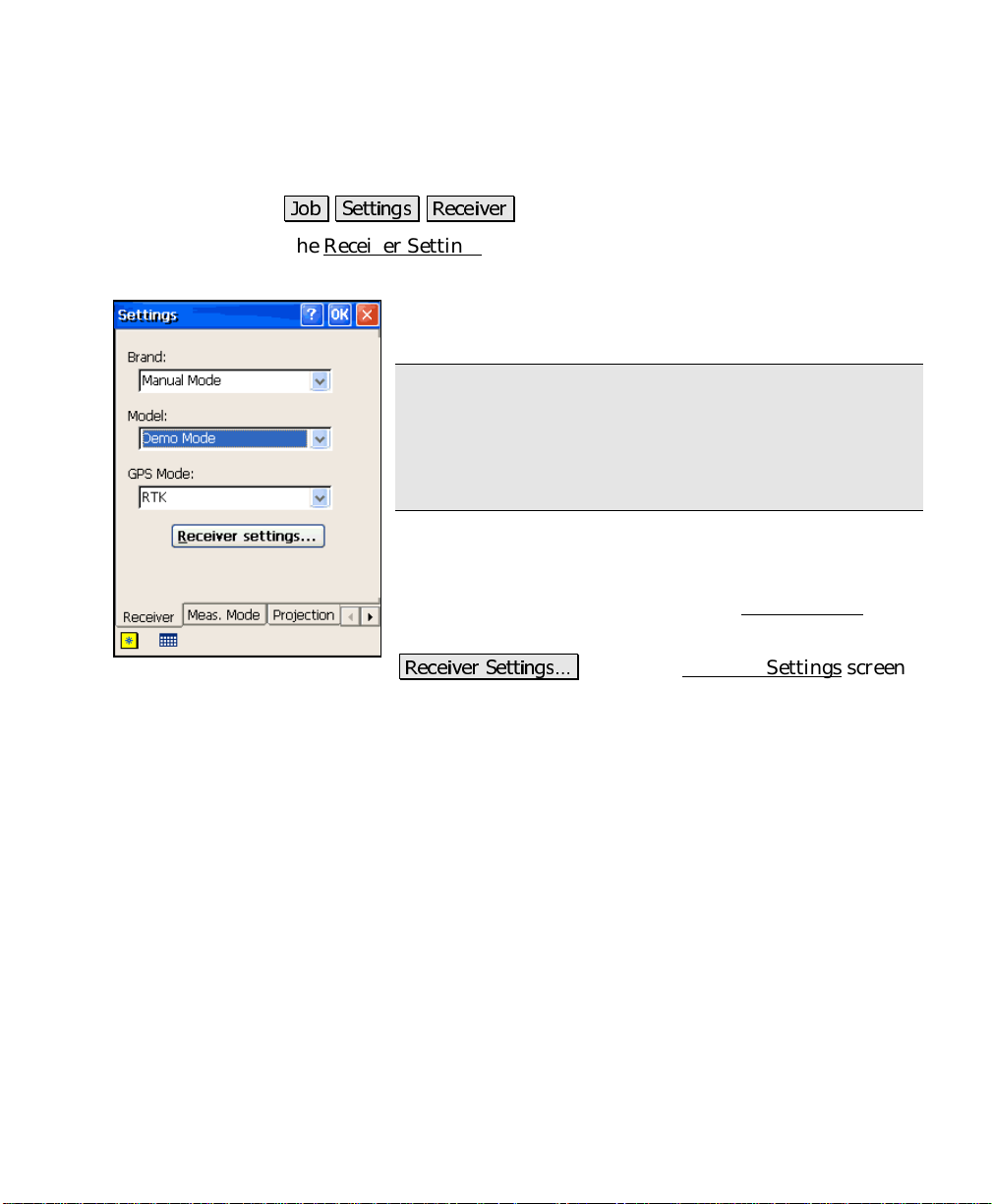
Receiver Settings
Job Menu
-RE 6HWWLQJV 5HFHLYHU
The Receiver Settings card is used to select the GPS receiver make
and model as well as the mode of differential data collection.
: is where you specify the manufact u rer of the
Brand
receiver you are using from a dropdown list.
Note: Many dialogs require connection to a receiver to
work. To open dialogs without a receiver, set the
to
Manual Mode
simulate RTK for training and demonstrations, set the
to
Model
: is where you specify the model of the receiver you
Model
are using from a dropdown list.
GPS Mode
RTK or post processing functions.
5HFHLYHU 6HWWLQJV«
(Page R-12), which is used to change the settings specific for t h e
receiver.
and the
Demo Mode
: toggles the content of the Survey Menu
.
: opens the Receiver Settings
Model
to
Manual Entry
Brand
. To
for
screen
7
Page 8
GPS Reference Manual
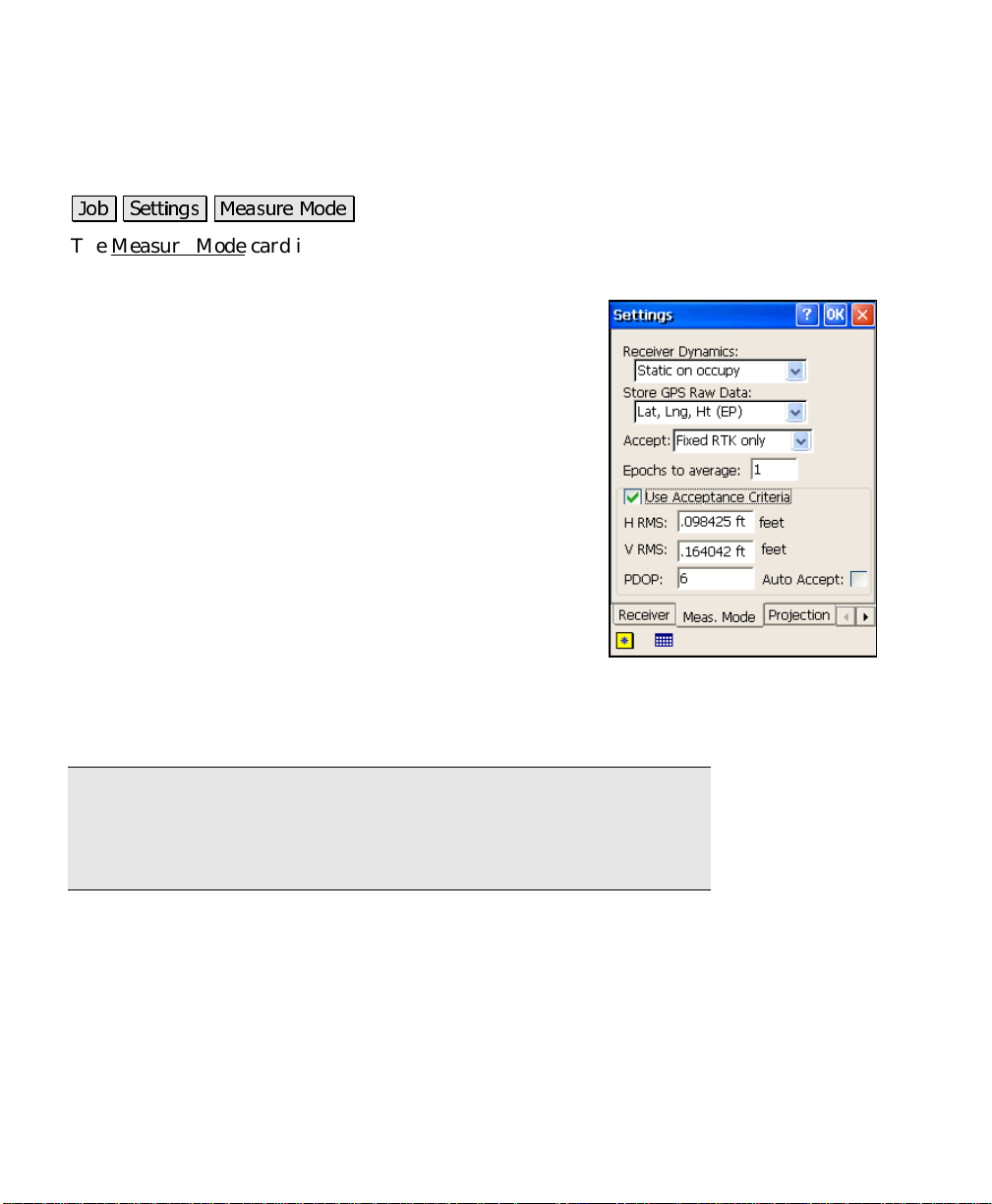
Measure Mode Settings
-RE 6HWWLQJV 0HDVXUH 0RGH
The Measure Mode card is used to configure the RTK data collection
settings.
Receiver Dynamics
dynamics for point occupations.
•
Static on occupy
occupation, receiver is put in static mode where
it calculates position assuming no motion and
applies advanced averaging techniques for the
most precise solution.
•
Dynamic always
mode for all point occupations.
Store GPS Raw Data
data storage. The following options are available:
•
Lat, Lng, Ht (EP)
(EP) record in the Survey Pro .RAW file for each
measurement.
•
EP + Bl,CV
and associated covariance matrix (CV) in the Survey Pro
.RAW file for each measurement.
Note: Ashtech receivers do not store base lines (BL) and covariance
(CV) records in the Survey Pro raw data file. Instead, they use a
separate Ashtech format .OBN file to store this information. The
user interface for Ashtech receivers will show OBN in place of BL,CV.
: is where you control the receiver
On starting a point
:
: Receiver is left in dynamic
: is where you set the mode for raw
: stores just a geodetic pos ition
: stores EP, the RTK base line measurement (BL)
8
•
EP + Bl,CV + Rx Raw
covariance matrix (BL,CV) in the Survey Pro .RAW file. Also
sends the station and antenna information to the receiver’s
internal raw data file for post processing.
•
EP + Rx Raw
sends the station and antenna information to the receiver’s
internal raw data file for post processing.
: stores EP in the Survey Pro .RAW file. Also
: stores EP, and the base line and
Page 9

Job Menu
Note: All receivers need to be in static mode to record Rx. Raw, and
some receivers always record Rx. Raw when in static mode. If the
combination of settings you select is not compatible for your receiver,
you will be prompted to change the settings..
Accept
: is where you control the solution quality acceptable for
storing measurements. You have two options:
•
Fixed RTK only
•
Code, Float, or Fix
Allows storage of fixed solution only.
:
: Allows storage of any differential
solution.
Epochs to Average on Accept
: is where you set the number of
epochs to average for the final coordinate. If this number is greater
than one, the final coordinate is calculated using an average of the
number of epochs specified.
Note: This function is not appropriate for every recei ver. Some
receivers, when dynamics are set to ‘static’, use Kalman filtering and
other superior techniques to cal culate an average position. In this
case, the position returned from the receiver is better with each epoch
and you may actually degrade your result by averaging with Survey
Pro. You should check with your receiver manufacturer for s pecific
recommendations on field procedure.
Use Acceptance Criteria
: is where you select to apply criteria to
measurement acceptance. When checked, only measurements with
RMS
and/or
PDOP
values below the threshold will be accepted. To
use less than all three criteria, check this box but enter 0.0 for the
criteria you do not wish to apply.
•
H RMS
: is the horizontal RMS threshold for automatic
acceptance or warning on point acceptance.
•
V RMS
: is the vertical RMS threshold for automatic
acceptance or warning on point acceptance.
•
PDOP:
warning on point acceptance.
is the PDOP threshold for automatic acceptance or
9
Page 10
GPS Reference Manual
Auto Acc e p t
acceptance. When checked, both the da ta and Offset Shots screens
will automatically accept points once the measurement is better than
the specified criteria.
is where you select to use criteria for automatic point
:
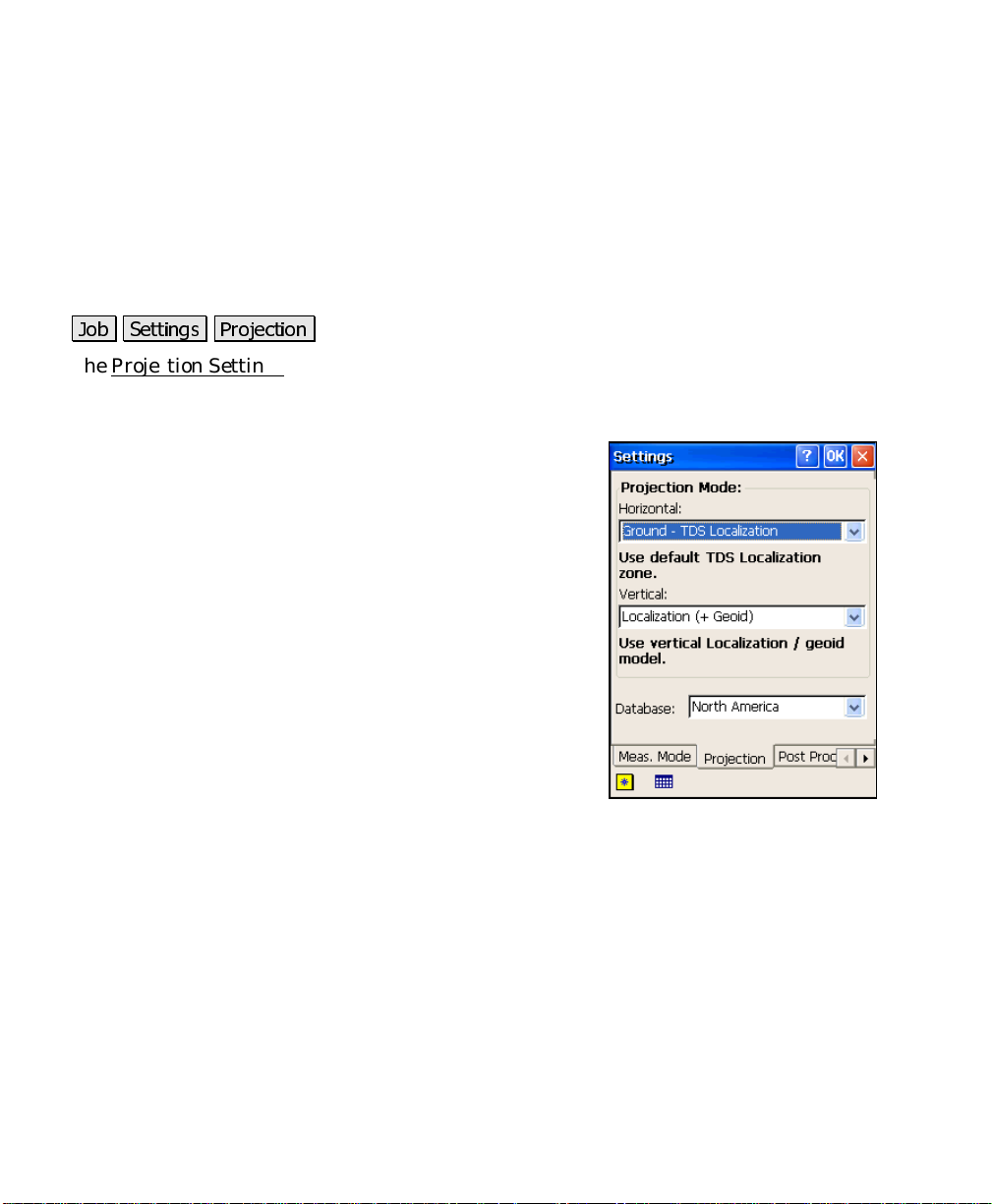
Projection Settings
-RE 6HWWLQJV 3URMHFWLRQ
The Projection Settings card is used to define the projection mode you
will use to calculate horizontal and vertical coordinates in your
survey.
Horizontal
horizontal projection.
•
•
Vertical
projection.
•
•
: contains the following options for your
Ground - TDS Localization
transform GPS coordinates into a ground level
local system using a default TDS map project ion
set up to produce ground distances at the GPS
base point origin.
Mapping Plane
GPS coordinates to a selected mapping plane
: contains the following options for your vertical
Localization (+Geoid)
geoid model with or without a localization
vertical adjustment.
Ellipsoid Height
measured ellipsoid heights is desired. Point elevations will be
local ellipsoid heights.
: use this setting to
: use this setting to transform
: use this setting to have a
: use this setting when no transformation of
Database
10
: is where you select the coordinate system database to use.
Page 11
Job Menu
Post Process Settings
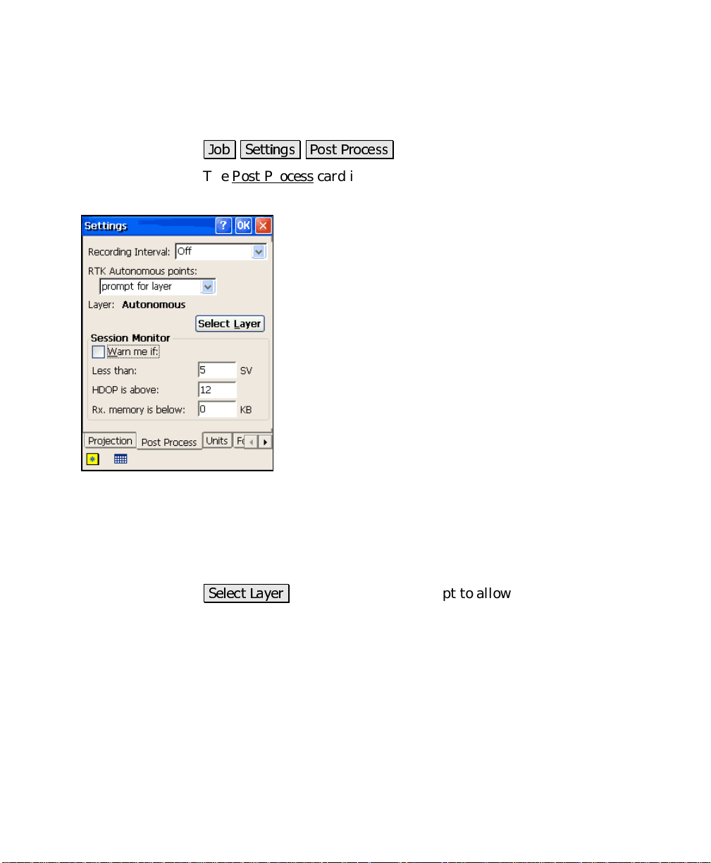
-RE 6HWWLQJV 3RVW 3URFHVV
The Post Process card is used to configure the post processing raw
data storage settings.
Recording Interval
receiver internal raw data recording. Set it to
disable post processing data collection in survey pro and
to turn off receiver recording on configuration.
RTK Autonomous Points
take when accepting autonomous points during RTK
data collection.
•
Do not store
of autonomous points in RTK data collection
routines.
•
Prompt for layer
user whenever an autonomous point is accepted.
The layer specified will be the default layer to
store autonomous points, but the user can over
ride at the prompt.
•
Store on selected layer
autonomous points accepted during RTK data collection
routines on the specified la yer.
: displays the layer selected to store autonomous points.
Layer
6HOHFW /D\HU
existing layer or create a new layer t o store autonomous points.
: opens up a layer prompt to allow you to select an
: is where you set the period for
to
Off
is where you specify action to
:
: this option will prohibit acceptance
: this option will prompt the
: this option will automatically store
Session Monitor
processing status for the session screen. To have Survey Pro display
warnings during post processing data collection, check
and specify threshold values for t h e number of SV,
memory
.
: is where you select to use monitoring of post
Wa rn me if
and
HDOP
,
11
Page 12
GPS Reference Manual
Note: This function only works during post processing data collection
using the session screen. For status during simultaneous post
processing and RTK data collection, refer to the status screens or the
RTK status bar.
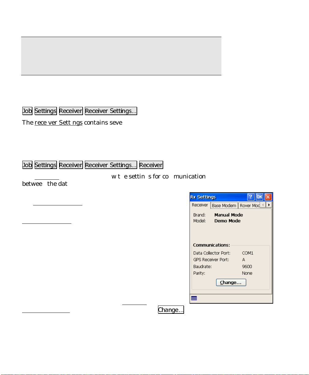
Receiver Settings
-RE 6HWWLQJV 5HFHLYHU 5HFHLYHU 6HWWLQJV«
The receiver Settings contains several settings specific to the selected
manufacturer and model of receiver. Some of these setting will vary
compared to what is displayed here.
Receiver Settings
-RE 6HWWLQJV 5HFHLYHU 5HFHLYHU 6HWWLQJV« 5HFHLYHU
The Receiver card is used to view the settings for communication
between the data collector and th e receiver.
: displays the receiver manufacturer selected in
Brand
the Receiver Settings
: displays the receiver model selected in the
Model
Receiver Settings
RTK Correction Format
between the base and rover.
Data Collector Port
collector used to communicate with the receiver.
GPS Receiver Port
receiver used to communicate with the data collector.
Baudrate
port. This speed must match the baud rate set in the
receiver, which can be set from the Receiver
Communications screen, opened by tapping th e
: displays the speed of the data collector’s COM
screen.
screen.
: is the format for communication
: displays the COM port on the data
: displays the COM port on the
&KDQJH«
button.
: displays the communications parity setting.
Parity
12
Page 13
Job Menu
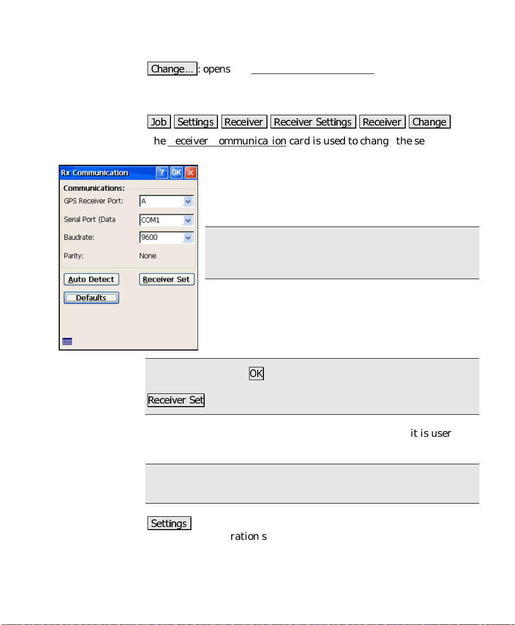
&KDQJH«
of the displayed communications settings can be changed.
: opens the Receiver Communications
screen, where many
Receiver Communication Screen
-RE 6HWWLQJV 5HFHLYHU 5HFHLYHU 6HWWLQJV 5HFHLYHU &KDQJH
The Receiver Communication card is used to change the settings for
communication between the data collector and the receiver.
GPS Receiver Port
the receiver. (
compatible total station for wireless communication
between the receiver and data collector.)
Note: See the conventional surveying User’s Manual for
more information on configuring Bluetooth with a
supported device.
Data Collector Port
on the data collector.
Baud Rate
rate.
Note: When you tap 2., the selected baud rate will only get set in
Survey Pro. To set the selected baud rate on the receiver, tap
5HFHLYHU 6HW
Parity
selectable).
.
: is where you select the communication parity (if it is user
: is where you select the communication baud
: is where you select the serial port on
Bluetooth
can also be selected when using a
: is where you to select the serial port
Note: For receivers where parity is not user definable, this field
simply displays the default parity.
6HWWLQJV
Bluetooth configuration screen that comes with the Bluetooth driver
software where you can quickly check or change the virtual COM port
and favorites.
: (only available when using Bluetooth) accesses the
13
Page 14
GPS Reference Manual
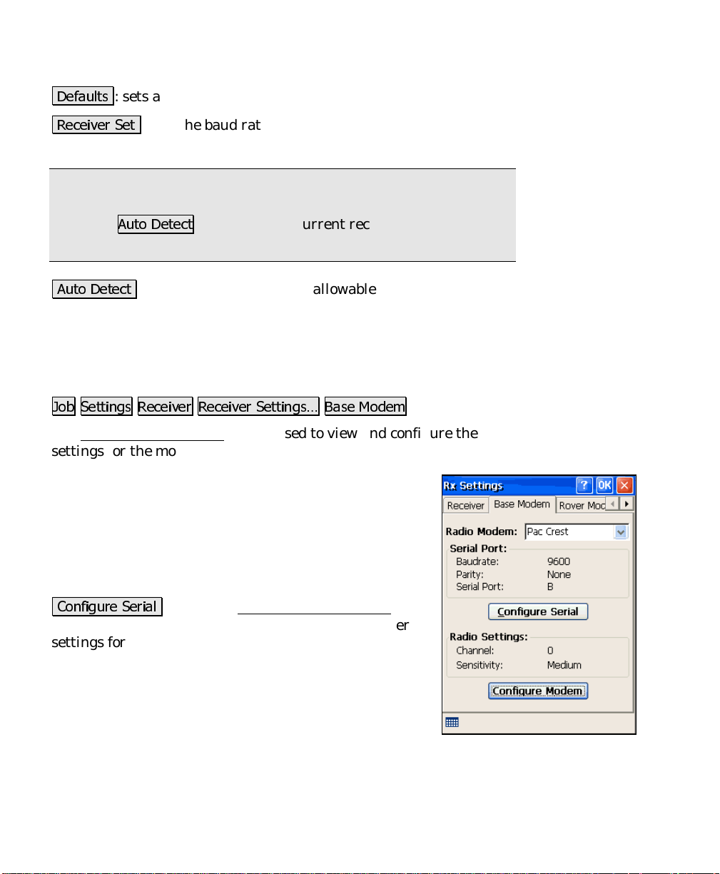
'HIDXOWV
: sets all the fields to the default values.
5HFHLYHU 6HW
selected value.
Note: This function requires that communication is already open
between the data collector and receiver. If communication is not
open, use
settings.
$XWR 'HWHFW
the current receiver communication settings. If this function
succeeds, Survey Pro is set to communicate at the baud found on the
receiver.
: sets the baud rate on the chosen receiver port to the
$XWR 'HWHFW
: checks the receiver at all allowable baud rates to find
first to get the current receiver communication
Base Modem Settings
-RE 6HWWLQJV 5HFHLYHU 5HFHLYHU 6HWWLQJV« %DVH 0RGHP
The Base Modem Settings card is used to view and configure the
settings for the modem used with the base receiver.
Baud Rate
to communicate with the radio.
Parity
communicate with the radio.
: displays the baud rate the receiver will use
: displays the parity the receiver will use to
Serial Port
to communicate with the radio.
&RQILJXUH 6HULDO
screen (Page R-15), where you can change the receiver
settings for radio communications.
Channel
applicable.
Sensitivity
applicable.
Mode
14
: displays the serial port the receiver will use
: opens the Radio Communications
: displays the last radio channel when
: displays the last radio sensitivity when
: displays the last radio base mode when applicable.
Page 15
Job Menu
&RQILJXUH 0RGHP
firmware and opens the Radio Settings screen (Page R-15), where you
can change the radio channel and sensitivity settings.
: establishes communicati on with the radio
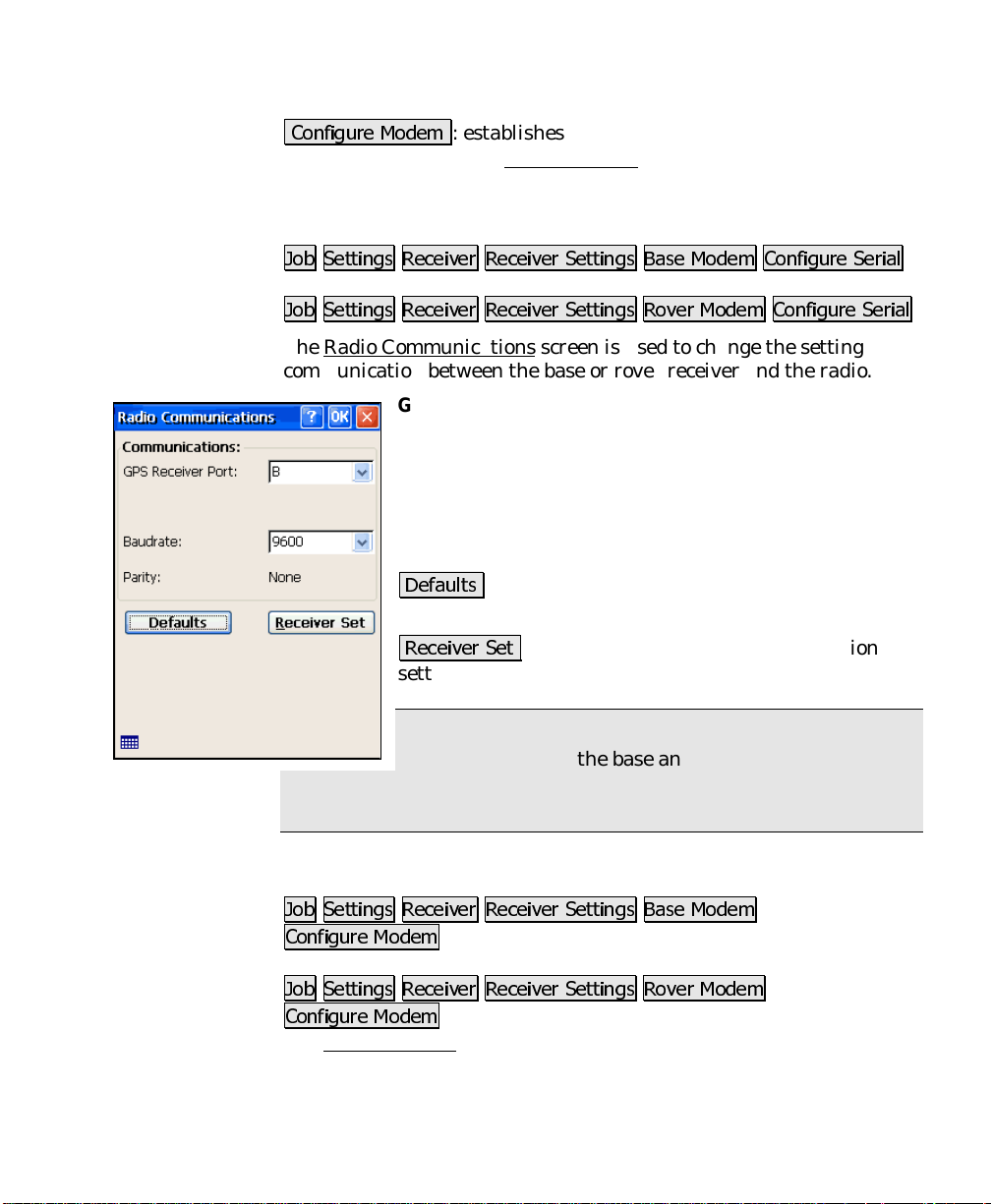
Radio Communications Screen
-RE 6HWWLQJV 5HFHLYHU 5HFHLYHU 6HWWLQJV %DVH 0RGHP &RQILJXUH 6HULDO
-or-
-RE 6HWWLQJV 5HFHLYHU 5HFHLYHU 6HWWLQJV 5RYHU 0RGHP &RQILJXUH 6HULDO
The Radio Communications screen is used to change the settings for
communication between the base or rover receiver and the radio.
GPS Receiver Port
the receiver will use to communicate with the radio.
Baudrate
will use to communicate with the radio.
Parity
the receiver will use to communicate with the radio.
'HIDXOWV
their defaults based on the selected hardware.
5HFHLYHU 6HW
settings in the receiver.
Note: The radio communication settings ar e also set in
the receiver during the base and rover setup procedure.
Therefore, you will not usually have to use the Receiver Set button on
this page.
: is where you select the baud rate the receiver
: When selectable, is where you select the parity
: automatically sets all the selectable values to
: is where you select the serial port
: sets the selected radio communication
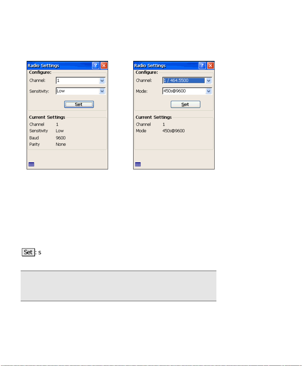
Radio Settings Screen
-RE 6HWWLQJV 5HFHLYHU 5HFHLYHU 6HWWLQJV %DVH 0RGHP
&RQILJXUH 0RGHP
-or-
-RE 6HWWLQJV 5HFHLYHU 5HFHLYHU 6HWWLQJV 5RYHU 0RGHP
&RQILJXUH 0RGHP
The Radio Settings screen is used to configure settings of the b ase or
rover radio mode. All settings available are described below.
15
Page 16
GPS Reference Manual
However, not all radios support all of the described settings, so if you
do not see one of these fields, it is because the radio type does not
support it.
Pac Crest Radio Settings screen Trimble Radio Settings screen
Channel
communicate with the other radio.
Sensitivity
Mode
Baud
Parity
6HW
selected on this screen.
Note: some settings on the radio cannot be modified with Survey Pro.
To fully program the radio modems, you need to PC software that
should be supplied with the radio.
16
: is where you select the channel the radio will use to
: is where you select the sensitivity of the radio.
: is where you select the base radio mode of the radio.
: displays the baud rate the radio is currently set to.
: displays the parity the radio is currently set to.
: sends commands to the radio firmware to configure the settings
Page 17
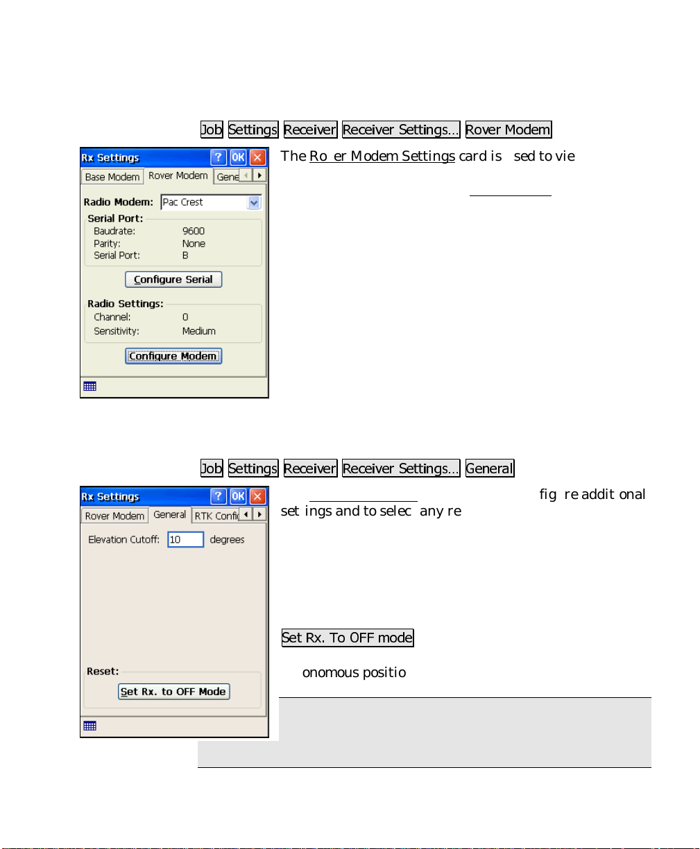
Rover Modem Settings
Job Menu
-RE 6HWWLQJV 5HFHLYHU 5HFHLYHU 6HWWLQJV« 5RYHU 0RGHP
The Rover Modem Settings card is used to view and
configure the settings for the modem used with the rover
receiver. It is identical to the Base Modem
on Page R-14.
General Settings
-RE 6HWWLQJV 5HFHLYHU 5HFHLYHU 6HWWLQJV« *HQHUDO
The General Settings card is used to configure additional
settings and to select any receiver-specific settings.
card described
operation.
Elevation Cutoff
elevation angle for using a satellite.
The available fi elds on this page are specific to the
selected receiver make and model. For further
information, see your receiver documentation.
6HW 5[ 7R 2)) PRGH
and rover) and puts the receiver into a standalone
autonomous position mode.
Note: This function is useful for some receivers that
have trouble communicating with radios during RTK
: is where you set the minimum
: Disables all RTK opera tion (base
17
Page 18
GPS Reference Manual
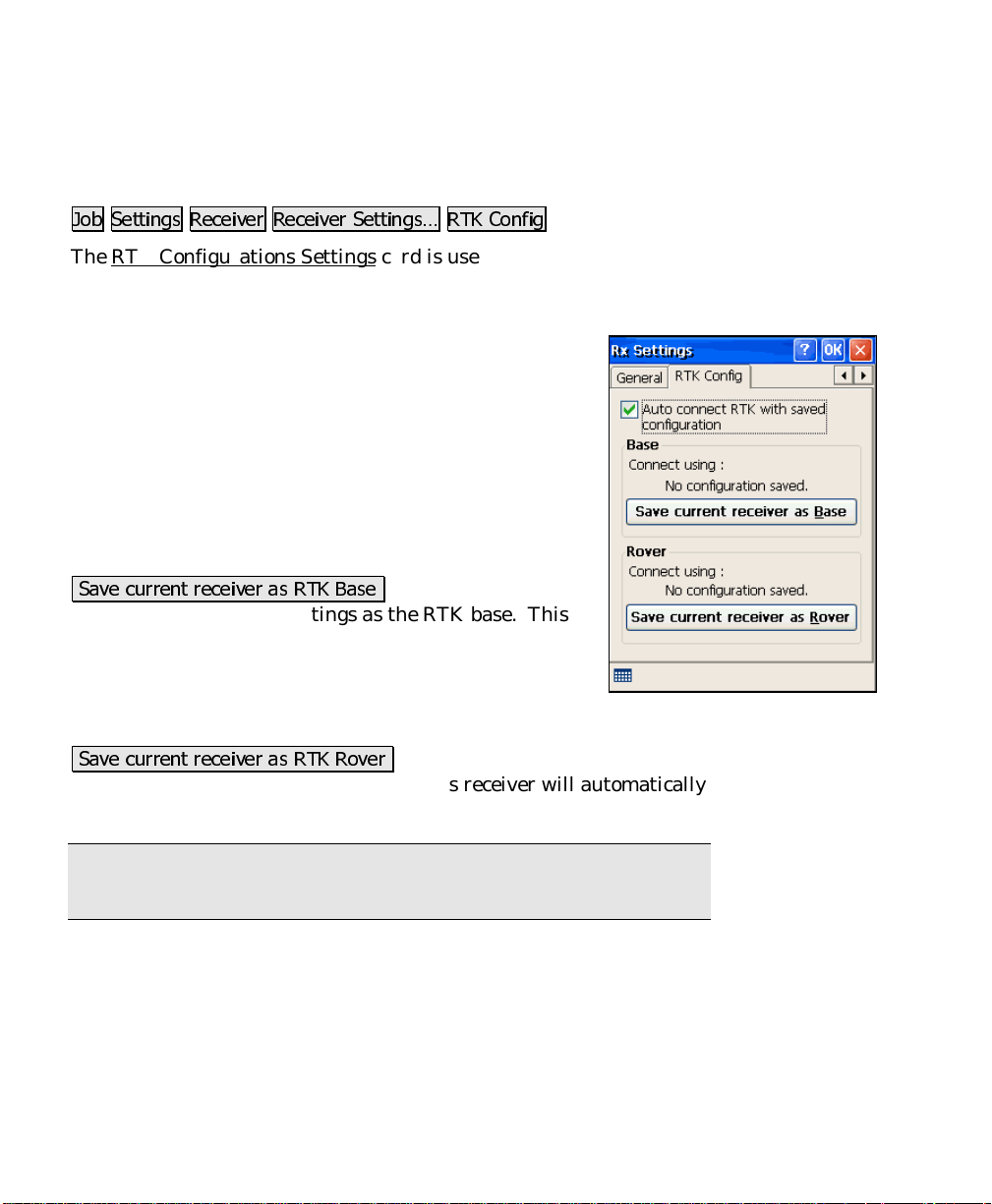
RTK Configurations
-RE 6HWWLQJV 5HFHLYHU 5HFHLYHU 6HWWLQJV« 57. &RQILJ
The RTK Configurations Settings card is used to configure automatic
connection when RTK base and rover receivers need to use different
COM ports and settings.
Auto connect RTK with saved configuration
you turn on the automatic connection function. When
selected, this feature will switch to the receiver brand
and model and set the port s ettings to the saved
configuration.
: Displays the brand and model of the saved base
Base
receiver configuration.
Connect Using
saved base receiver configuration.
6DYH FXUUHQW UHFHLYHU DV 57. %DVH
receiver and COM port settings as the RTK base. This
receiver will automatically be set when you tap Base
Setup in Survey Pro.
: Displays the brand and model of the saved rover
Rover
receiver configuration.
6DYH FXUUHQW UHFHLYHU DV 57. 5RYHU
COM port settings as the RTK rover. This receiver will automatically
be set when you tap Rover Setup in Survey Pro.
: Displays the COM port settings for the
: Saves the current
: Saves the current receiver and
: is where
Note: If you need to connect to a receiver different than the saved
configuration, you can un-check the Auto Connect control.
18
Page 19

Survey Menu – RTK
The Survey Menu contains the routines used for collecting data. The
screens below are available only when running Survey Pro in RTK
mode. The screens available when running in Post Processing mode
are described in the next section.
A: GPS Status
B: Base Setup
C: Rover Setup
D: Control Points
E: Data Collection
F: Projection
G: Receiver Recording
H: Receiver Info
I: Readjust Points
J: Projection Calculator
19
Page 20
GPS Reference Manual
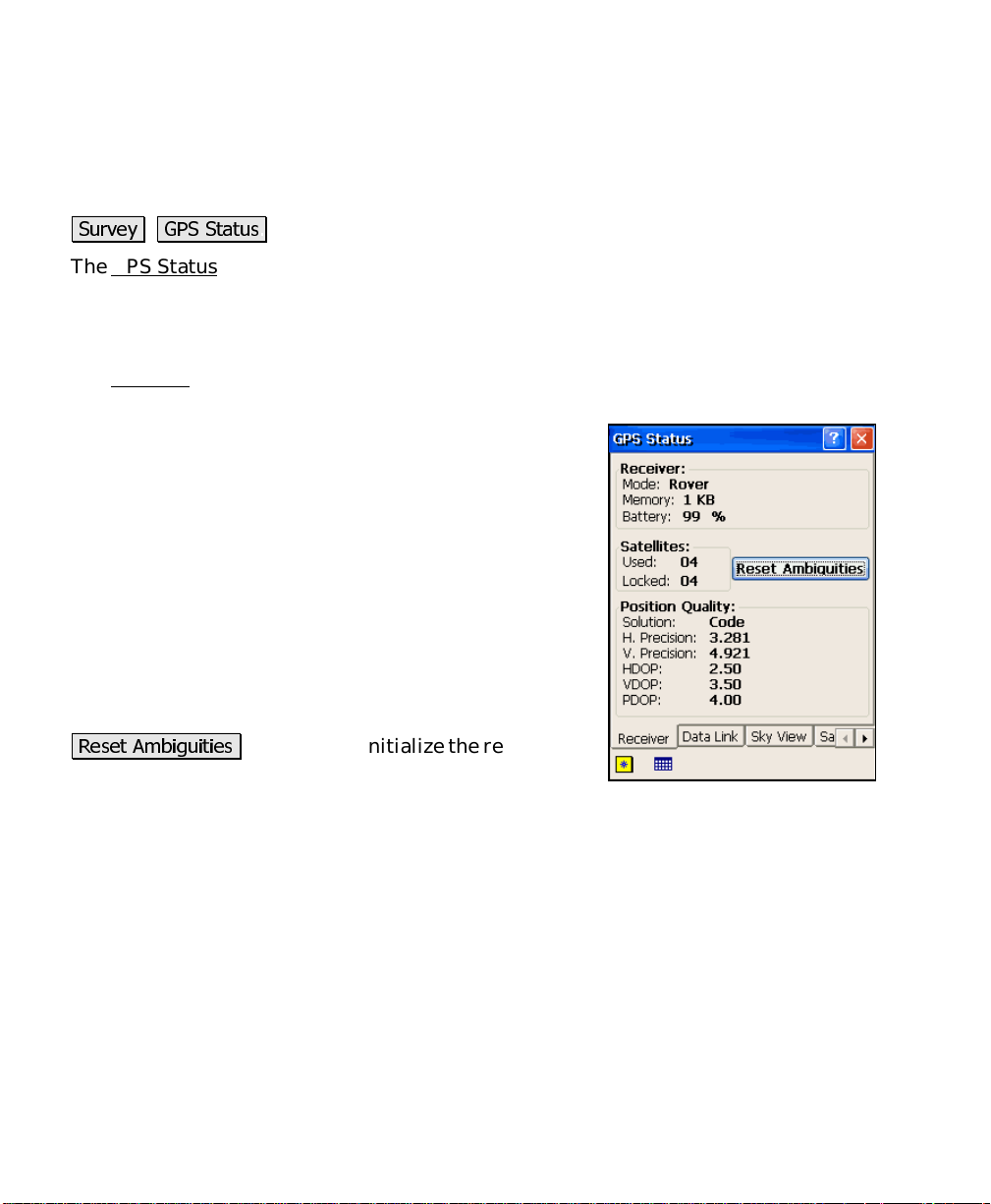
GPS Status
6XUYH\ *36 6WDWXV
The GPS Status screen contains several index card-format screens
providing information about the current GPS solution.
Receiver
The Receiver card displays information about the receiver mode and
GPS solution quality.
displays if the receiver is set to
Mode
:
or
Post Processing
Memory
the receiver’s internal storage card.
Battery
receiver.
Satellites
5HVHW $PELJXLWLHV
RTK engine.
: displays the amount of memory remaining in
: displays the remaining battery charge in the
: displays the number of satellites:
•
Used
solution.
•
Locked
mode.
: by the receiver for the current GPS
: (Tracked) by the receiver.
: is used to reinitialize the receiver’s
Off, Base, Rover
,
Solution
the following values:
20
: displays the type and quality of solution. It will be one of
•
No Communication
commands.
•
No Data
commands.
•
No RTK Solution
receiver is not computing a solution.
•
Autonomous
(accuracy is about 100 meters).
: we are receiving an unknown or a bad response to
: we are not receiving a response to
: we are receiving a response, but the
: we are receiving a stand-alone solution
Page 21

•
: we are receiving a code differential solution (precision
Code
is about 1 to 10 meters).
Survey Menu – RTK
•
: we are receiving a carrier phase differential solution
Float
with float ambiguities (precision is typically within 0.1_m to
0.5_m).
•
: we are receiving a carrier phase differential solution
Fixed
with fixed ambiguities (precision is typically within 15_mm
for single-frequency receivers and 5_mm for dual-frequency
receivers).
H Precision
: displays the root mean squared (RMS) error of the
horizontal solution reported by the receiver. It is displayed in project
units.
V Precision
: displays the RMS error of the vertical solution reported
by the receiver. It is displayed in project units.
: displays the Horizontal Dilution of Precision. It is a measure
HDOP
of the geometrical quality of the solution. DOP has no units and
lower numbers indicate better solution geometry.
: displays the Vertical Dilution of Precision. It is a measure of
VDOP
the geometrical quality of the solution.
: displays the Position Dilution of Precision. It is a combination
PDOP
of HDOP, VDOP and Time Dilution of Precision. It will always be
larger than HDOP and VDOP.
21
Page 22
GPS Reference Manual
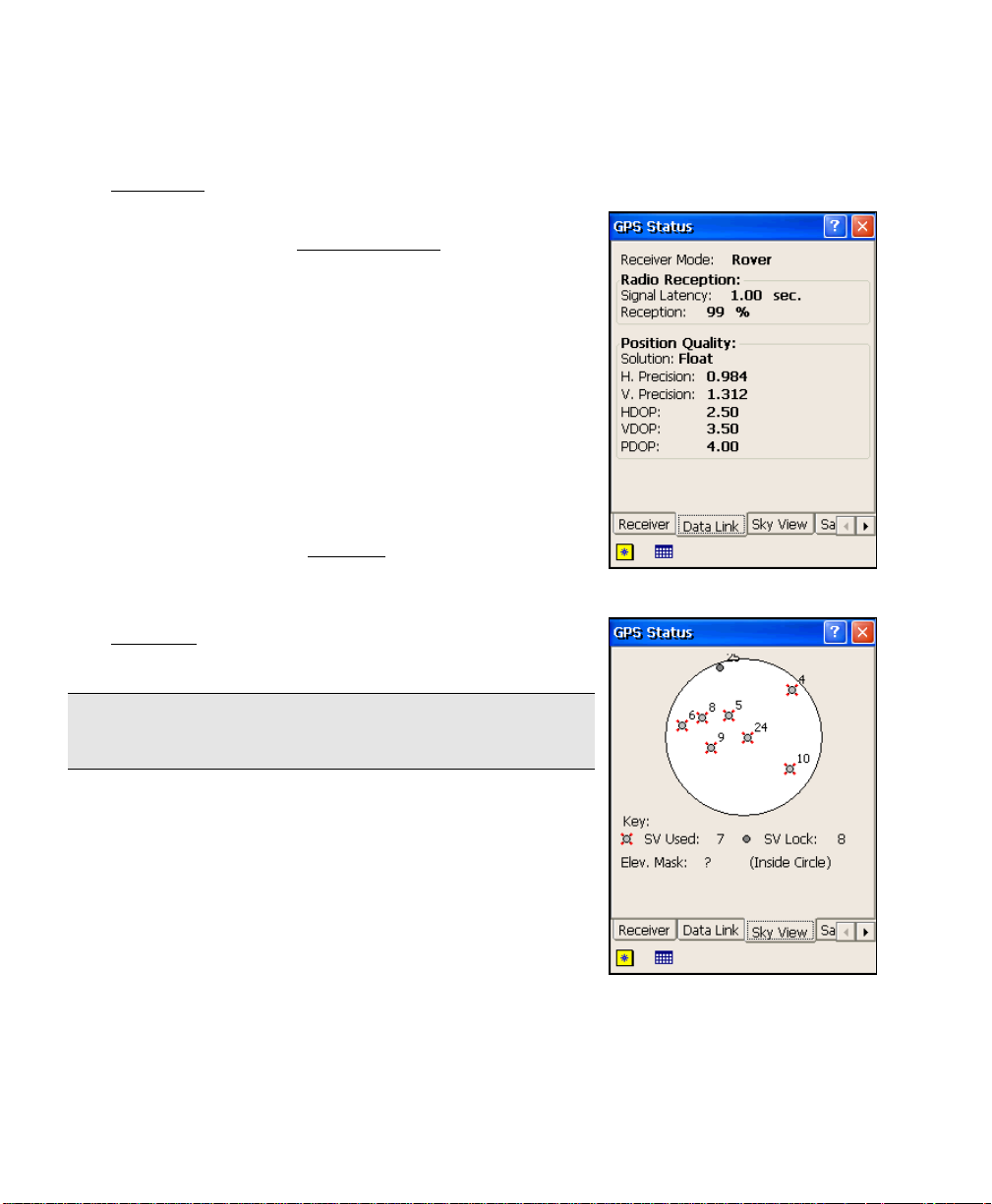
Data Link
The Data Link card displays information about the radio
communications.
Receiver mode
Radio Reception
signal quality. This information is only displayed if the
receiver is in rover mode.
Signal Latency
correction used in the current GPS solution. This value
should be one second or less for good RTK solutions. If
this value is consistently greater than one second, check
the radio link.
Reception
percent quality of the radio link.
Position Quality
: (see the Receiver Status card, above.)
: displays two values indicating radio
: displays the age of the differential
: displays the receiver’s estimation of the
: (see the Receiver
card on Page R-20.)
Sky View
The Sky View card displays a plot of the satellites
tracked and the elevation mask boundary.
Note: If the receiver setup has not yet been performed,
the elevation mask will not be displayed.
22
Page 23
Survey Menu – RTK
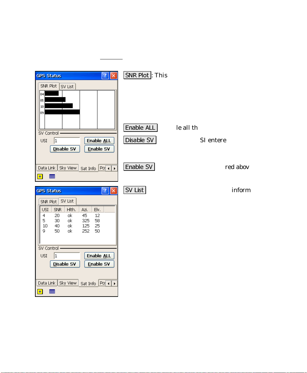
Sat Info
The Sat Info card displays signal quality information for the satellites
that are being used and allows you to disable specific satellites.
615 3ORW
view and shows a bar graph that indicates the signal-tonoise ratio. A longer bar indicates more noise, and a
lower-quality signal.
USI
to disable or re-enable.
(QDEOH $//
'LVDEOH 69
satellite will then no longer be used in any solution until
it is re-enabled.
(QDEOH 69
69 /LVW
each satellite being used, which is reported by the
receiver. The columns available depend on the receiver
being used. Consult your receiver’s documentation for
more information.
: This card lists all the satellites that are in
: is the satellite identification number that you wish
: enable all the satellites that were disabled.
: disables the USI entered above. This
: re-enables the USI entered above.
: This card lists signal quality information for
23
Page 24
GPS Reference Manual
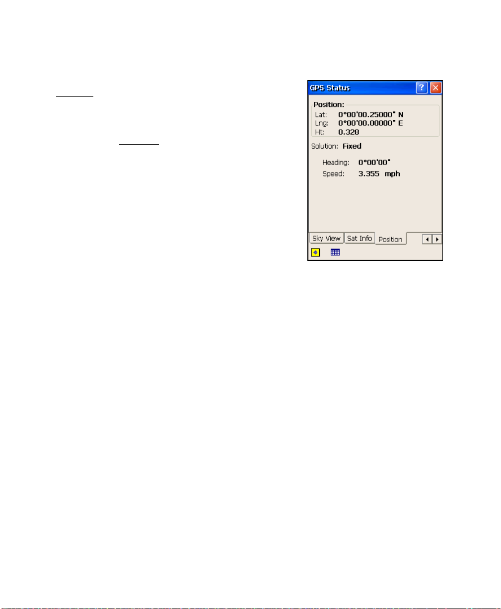
Position
The Position card displays your current position as well
as your course and speed information if you are moving.
Position
Solution
Heading
moving.
Speed
are moving.
: displays your current coordinates.
: (see the Receiver
: displays your course over ground if you are
: displays your horizontal speed over ground if you
card on Page R-20.)
24
Page 25
Base Setup
Survey Menu – RTK
6XUYH\ %DVH 6HWXS
The Base Setup screen is used to set the base point in Survey Pro and
to configure the receiver to begin broadcasting differential
corrections.
Note: If you are in
for the purposes of doing GPS calculations without having to connect
to a receiver.
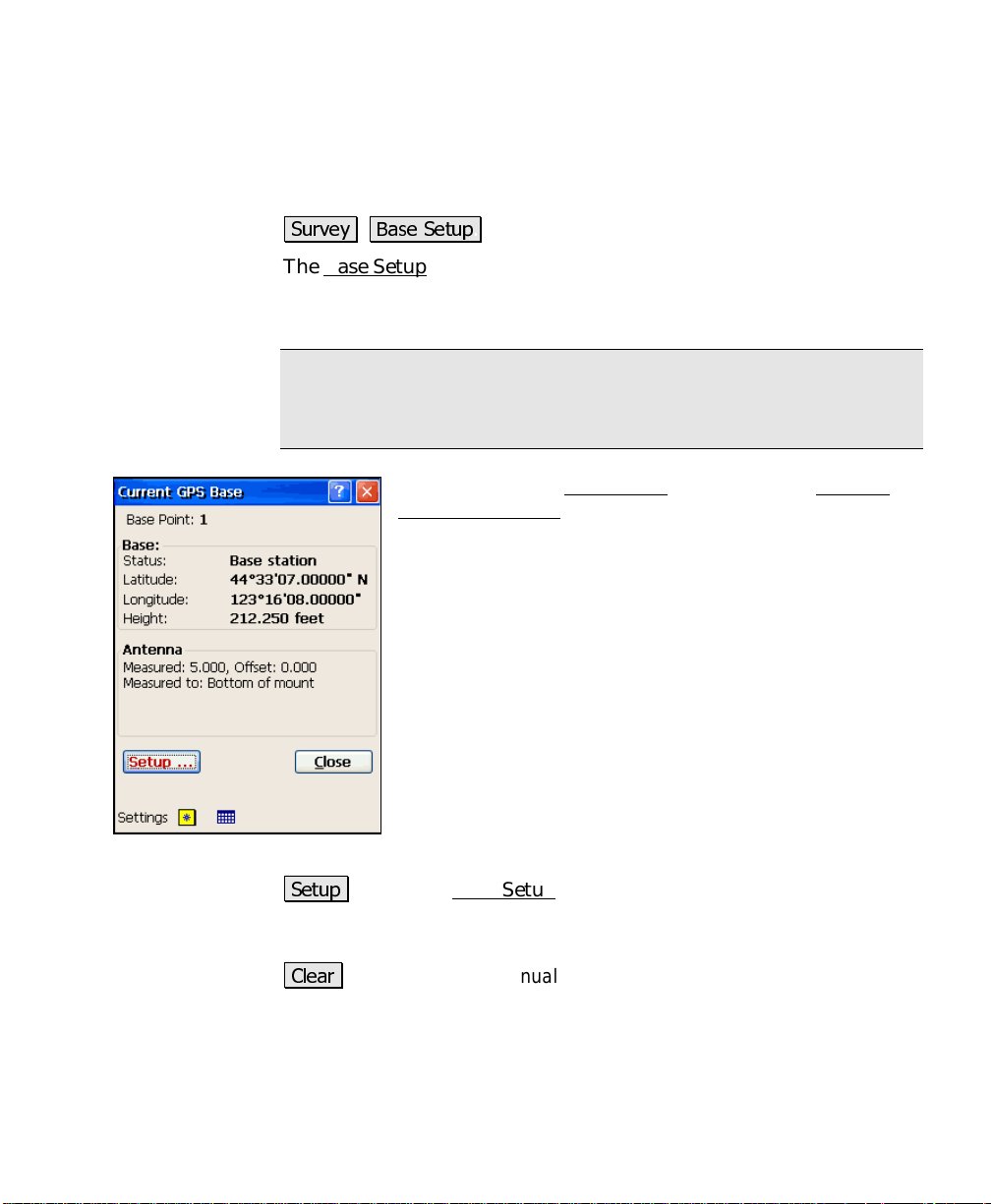
When you tap the Base Setup menu item, the Current
GPS Base Station information screen is displayed.
Base Point
Base:
Manual Mode
: displays the current base point name, if set.
•
Status
•
Latitude
point set in Survey Pro.
•
Longitude
base point set in Survey Pro.
•
Height
point set in Survey Pro.
, you can set the base in Survey Pro
: displays the status of the base.
: displays the current latitude of the base
: displays the current longitude of the
: displays the current height of the base
Antenna
available.
6HWXS
: opens the Base Setup
set and the receiver configured for RTK and post processing data
collection.
&OHDU
: (visible only in
setup so you edit the point if necessary.
: displays information about the antenna if it is
wizard where the base position can be
Manual Entry
mode) clears the existing base
25
Page 26
GPS Reference Manual
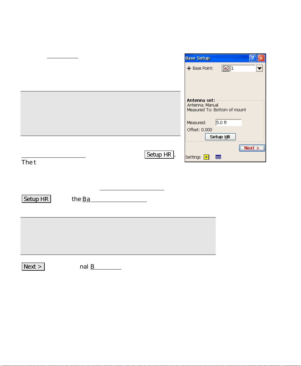
Base Setup One – Pick Base Point
The first Base Setup screen is used to pick the base point
and set the antenna height.
Base Point
base antenna is set up over.
Note: You can enter either an existing point or a new
point name into the Base Point control. If you enter a
new point name, the routine will create a new point
record in the job file at the end of successful base station
configuration.
Antenna
Base Receiver Antenna
The title of this field changes depending on if the
antenna has already been setup.
Measured
the location specified on the Base Receiver Antenna
6HWXS +5
where the details of the base antenna are defined.
Note: the antenna information and receiver serial number is stored
in the registry. When you setup the base or rover receiver and the
receiver serial number matches a number stored in the registry, the
associated antenna parameters are automatically recalled.
: is where you enter the point name that the
: displays antenna information defined from the
screen after tapping
: is where you enter the height of the antenna, measured to
: opens the Base Receiver Antenna
6HWXS +5
screen (Page R-29)
.
screen.
1H[W !
on the base point you choose:
• If the base point has existing geodetic coordinates, or if they can
26
: opens the final Base Setup
be computed from 3D plane coordinates and the latest projection
solution, the final screen allows you to SET the receiver with the
known position.
screen. The final screen depends
Page 27
Survey Menu – RTK
• If the base point does not have geodetic coordinates or if geodetic
coordinates cannot be computed for this point, the final screen is
used to GET an autonomous position and set the receiver.
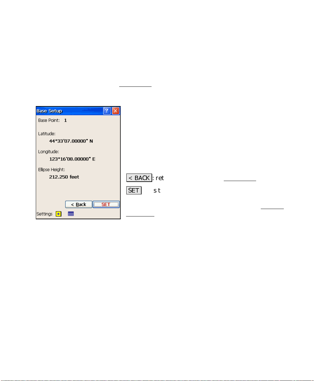
Base Setup Two – SET
This final Base Setup screen is used to SET the known base position
in Survey Pro and in the receiver. This screen will open when the
base point has measured or computed geodetic coordinates in the job.
Base Point
previous screen.
Latitude
Longitude
point.
Ellipse Height
the base point.
%$&.
6(7
configures the receiver to begin broadcasting differential
corrections. When successfully completed, the Current
GPS Base information screen returns with the new base
station information.
: displays the base point name chosen in the
: displays the current latitude for the base point.
: displays the current longitude for the base
: displays the current ellipsoid height for
: returns to the previous Base Setup
: sets the base position in Survey Pro and
screen.
27
Page 28
GPS Reference Manual
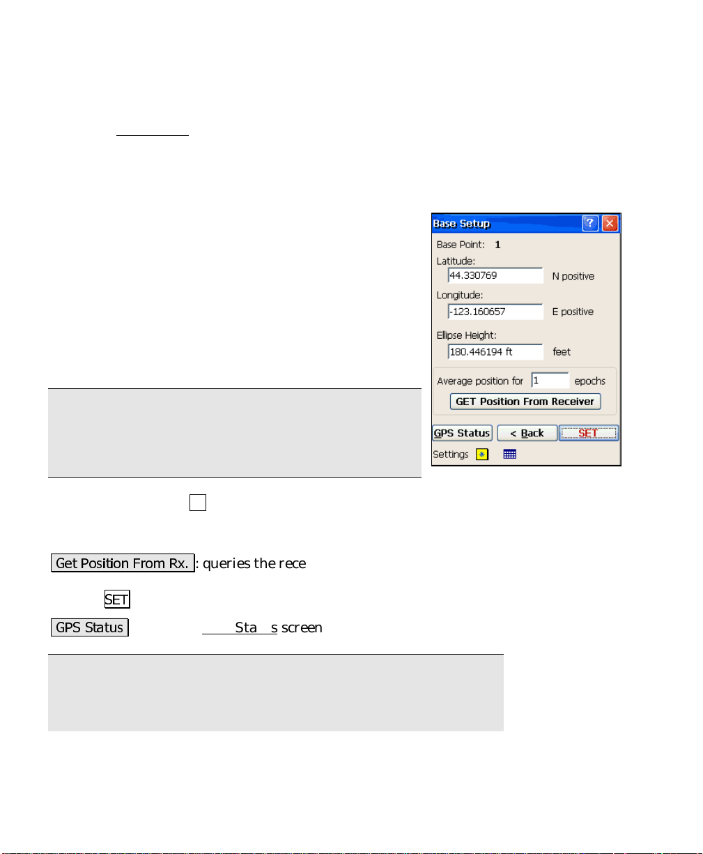
Base Setup Two – GET and SET
This final Base Setup screen is used to GET an autonomous (here)
position from the receiver and to SET that base position in Survey
Pro and in the receiver. This screen will open when the point is a
new point in the job file, or, in Localization mode when this is the
first geodetic point i n the job.
Base Point
previous screen.
Latitude
base point.
Longitude
the base point.
Ellipse Height
height for the base point.
Note: You can enter latitude in dd.mmsssss format with
north positive, or you can enter dd mm ss.ssssss N/S.
You can enter longitude in ddd.mmsssssss format with
east positive or you can enter ddd mm ss. sssss E/W.
Average position for epochs before GET
average autonomous positions for this number of epochs before
returning.
*HW 3RVLWLRQ )URP 5[
position. This position can then be used to configure the base by
tapping
: displays the base point name chosen in the
: is where you enter the WGS84 latitude for the
: is where you enter the WGS84 longitude for
: is where you enter the WGS84 ellipsoid
: instructs the receiver to
: queries the receiver for an autonomous
6(7
.
*36 6WDWXV
Note: It is highly recommended that you do only one autonomous
base setup per job. This will make it much easier to manage the
transformation from geodeti c to local plane coordinates in your job. It
is possible, however, to do multiple autonomous setups in a job. If
28
: opens the GPS Status
screen (Page R-20).
Page 29
Survey Menu – RTK
you do this, each setup is assigned a unique setup group to identify
them. See the user's manual for more informat ion on setup groups.
6(7
: sets the base position in Survey Pro and configures the receiver
to begin broadcasting differential corrections. When successfully
completed, the Current GPS Base
information screen returns with
the new base station information.
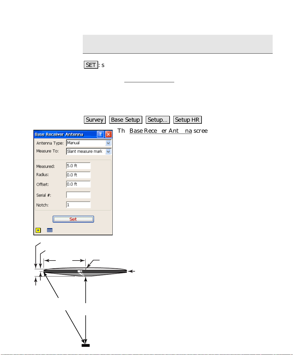
Base Receiver Antenna
Vertical Offset
Slant Offset
Radius
Slant
Height
6XUYH\ %DVH 6HWXS 6HWXS« 6HWXS +5
The Base Receiver Antenna screen is used to define the
parameters of the antenna used with the base receiver.
Antenna Type
: is where you select the model of antenna
to use. The options available here depend on the current
receiver.
Measure To
: is where you select method for antenna
height measurements. Most antennas have only t wo
choices, measure to bottom of mount, or a visible slant
measure mark.
Measured
: is where you enter the height of the antenna,
measured to the location specified in the
field.
Radius
: is where you enter the distance from the
antenna’s center to the measuring mark on its outer
edge.
Offset
Phase Center
Measurement
Point
distance measured from the
location, to the phase center.
To
Serial#
antenna. This information is only
written as a note in the raw data.
Vertical
Height
Notch
antenna that you are measuring to.
Measure To
: is where you enter the vertical
Measure
: is the serial number of the
: Is the notch number on the
Marker
29
Page 30
GPS Reference Manual
Note: If your antenna type is Manual, the Radius and Notch fields
will not be available
6HW
: Updates the base antenna sett ings with the values selected on
this screen.
Note: When this screen is used by the RTK rover for updates of
antenna height during a survey, the Set button will send the new
antenna parameters to the receiver as well as updating Survey Pro's
settings.
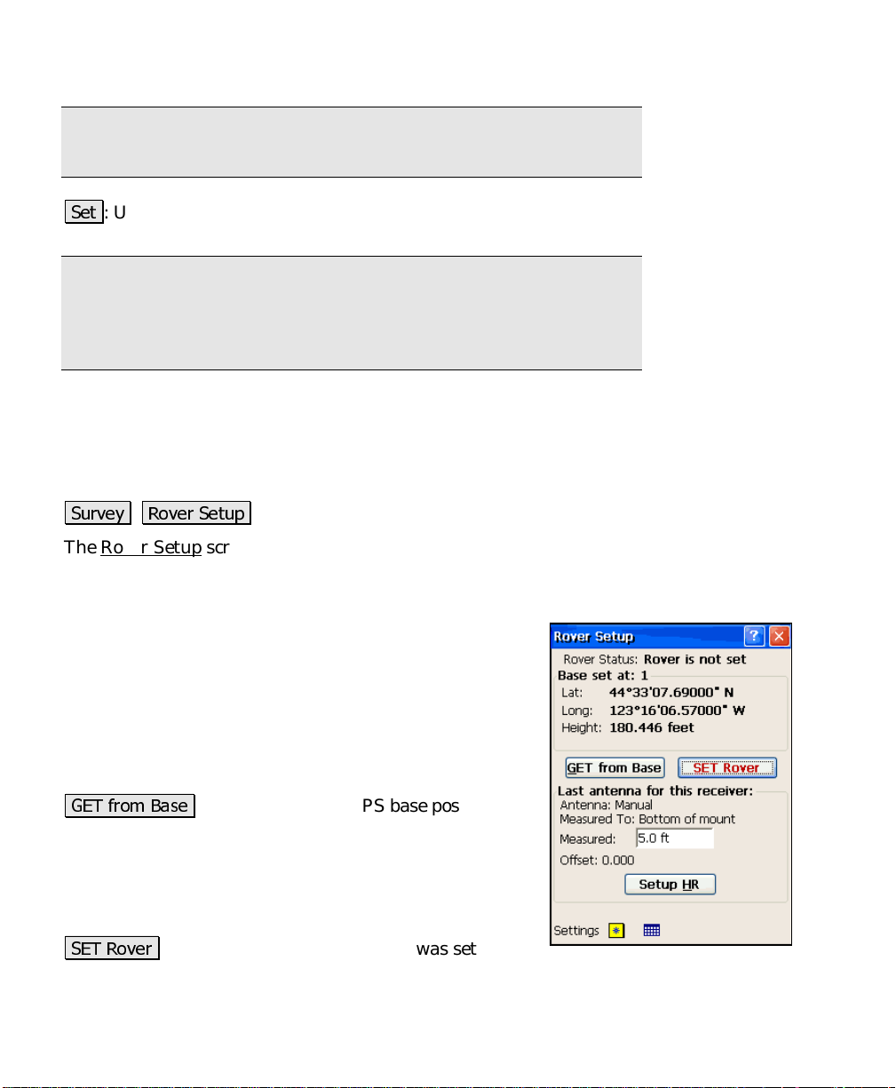
Rover Setup
6XUYH\ 5RYHU 6HWXS
The Rover Setup screen is used to configure an RTK rover to begin
receiving differential corrections and to start the survey with the base
reference position.
Rover Status
Base set at
empty if the base is not set.
•
•
•
*(7 IURP %DVH
not known to this data collector. This function will get
the base station’s geodetic coordinate over the radio link
and set the base position in Survey Pro. It will then
configure the rover receiver to start receiving differential
corrections.
6(7 5RYHU
30
: displays the status of the rover.
: displays the current base point. This will be
: displays the latitude of the base.
Lat
: displays the longitude of the base.
Long
Height
: displays the ellipsoid height of the base.
: is used when the GPS base position is
: is used when the base station was set with
Page 31

Survey Menu – RTK
this data collector. This function configures the rover with the
displayed geodetic coordin ate.
Last Antenna for this Receiver
from the Rover Receiver Antenna
title of this field changes depending on if the antenna has already
been setup.
Measured
the location specified on the Rover Receiver Antenna
6HWXS +5
identical to the Base Receiver Antenna screen discussed on Page R-29
where the details of the rover antenna are defined.
Note: the antenna information and receiver serial number is stored
in the registry. When you setup the base or rover receiver and the
receiver serial number matches a number stored in the registry, the
associated antenna parameters are automatically recalled.
: is where you enter the height of the antenna, measured to
: opens the Rover Receiver Antenna
: displays antenna information defined
screen, opened from
screen, which is
6HWXS +5
screen.
. The
Rover Receiver Antenna
6XUYH\ 5RYHU 6HWXS 6HWXS +5
The Rover Receiver Antenna screen is used to define the parameters
of the antenna used with the rover receiver. The screen is identical to
the Base Receiver Antenna screen, which is described on Page R-29.
31
Page 32

GPS Reference Manual
Control Points
6XUYH\ &RQWURO 3RLQWV
The Control Points screen is used to measure or check control points
in the projection solution.
GPS Status
signal quality, number of satellites used, and the
receiver’s estimate of the horizontal precision of the
current point. If this area is tapped, the GPS Status
screen will open (Page R-20).
Point
you are occupying.
Rover
rover antenna.
6HWXS +5
which is identical to the Base Receiver Antenna screen
discussed on Page R-29 where the details of the rover
antenna are defined.
3URMHFWLRQ
9LHZ 3RLQW
project points can be examined.
3RVW 3URFHVV
R-76.
: displays the current solution type, radio
: is where you enter the name of the control point
: is where you enter the measured height of the
: opens the Rover Receiver Antenna
: opens the Projection
: opens the View Coordinates File
: opens the Receiver Session
screen,
screen (Page R-40).
screen, where the
screen, described on Page
&KHFN
coordinate computed from the measurement is compared to the local
coordinates known value.
&RQWURO
where geodetic coordinates are measured to a point with local
coordinates and stored in the job file.
32
: opens the Check Control Point
: when available, opens the Occupy Cont rol Point
screen, where the local
screen,
Page 33

Manual Entry GPS
Survey Menu – RTK
6XUYH\ &RQWURO 3RLQWV &RQWURO
The Manual GPS screen allows you to manually enter geodetic
coordinates from the Control Points
must have your
Manual Entry
manual entry screen.
on the Job
Local Coordinates:
selected control or check point
Latitude
point.
Longitude
the point.
Ellipse Height
height of the point.
$FFHSW
plane point record and flags this point as a GPS control
point.
set to
Brand
| Settings | Receiver screen to open the
: is where you enter the WGS84 latitude of the
: is where you enter the WGS84 longitude of
: is where you enter the WGS84 ellipsoid
: adds the WGS84 geodetic coordinates to the
and Check Points routines. You
Manual Mode
is the local plane coordinate of the
and your
Model
set to
Check Control Point Screen
6XUYH\ &RQWURO 3RLQWV &KHFN 3RLQW
The Check Control Point screen is used to check a control point. This
is done when you want to verify the quality of the local projection
setup.
Coordinates
current measurement and the latest project ion solution.
Solution Quality
the solution type, the number of satellites used, and the horizontal
and vertical precision computed by the receiver.
: displays the local coordinates computed using the
: displays the quality of the current measurement:
33
Page 34

GPS Reference Manual
Errors
coordinates and the known coordinates for the control point.
: displays the differences between the computed local
Note: If the
instrument, you probably have a problem with your projection
solution.
Epochs
the beginning of data collection.
Count Status
fresh coordinates from the receiver and updating the
screen with the latest measurement.
displayed after you tap
number of epochs specified in the
Accept
value is greater than 1).
are not receiving valid data from the receiver or while
you are viewing a separate screen (like GPS Status
*36 6WDWXV
Status screen (Page R-20).
$FFHSW
to the Control Points screen.
: displays the number of epochs recorded since
field on the Measure Mode Settings
: stops the epoch counter and opens the GPS
: writes the results to raw data and returns you
are larger than the measurement preci sion of the
Errors
: displays
Measuring
$FFHSW
Suspended
when we are receiving
Averaging
while we average the
Epochs to Average on
is displayed if we
is
screen (if this
).
34
Page 35

Occupy Control Point Screen
Survey Menu – RTK
6XUYH\ &RQWURO 3RLQWV &RQWURO
The Occupy Control Point screen is used to add geodetic coordinates
for a known project point. The most common use of this screen is to
measure control points for the localization solution. This screen is
also used by the Localization Calculator
point localization setup.
Geodetic Coordinates
measured to the current control point.
Solution Quality
measurement: the solution type, the number of satellites
used, and the horizontal and vertical precision computed
by the receiver.
Control Point
to be used for
tapping the appropriate checkboxes.
Epochs
the beginning of data collection.
Count Status
fresh coordinates from the receiver and updating the
screen with the latest measurement.
displayed after you tap
epochs specified in the
Measure Mode Settings
Suspended
receiver or while you are viewing a separate screen (like GPS Status
is displayed if we are not receiving valid data from the
: is where you select if the current point is
Horizontal
: displays the number of epochs recorded since
: displays
$FFHSW
Epochs to Average on Accept
screen (if this value is greater than 1).
routine (Page R-54) for one
: displays the geodetic coordi nates
: displays the quality of the current
control and/or
Measuring
while we average the number of
Vertical
when we are receiving
Averaging
field on the
control by
is
).
*36 6WDWXV
screen (Page R-20).
$FFHSW
Control Points screen.
: stops the epoch counter and opens the GPS Status
: accepts the current control point and returns you to the
35
Page 36

GPS Reference Manual
Data Collection
6XUYH\ 'DWD &ROOHFWLRQ
The Data Collection screen is used to collect new points for the
current job.
GPS Status
reception quality, the number of satellites used and the
horizontal precision computed by the receiver. When
this area is tapped, the GPS Status
will open.
Point
point to be stored.
Description
next stored point.
Rover
rover antenna.
6HWXS +5
on Page R-29 where the detai ls of the antenna are
defined.
3RVW 3URFHVV
R-76.
&RQWURO 3RLQW
: displays the current solution type, the radio
: is where you enter the point name for the next
: is where you enter the descript ion for the
: is where you enter the measured height of the
: opens the Receiver Antenna
: opens the Receiver Session
: opens the Control Point
screen (Page R-20)
screen discussed
screen, described on Page
screen (Page R-31).
)HDWXUH
automatic and manual data collection options are available.
2IIVHW
and stored at a specified offset.
3RLQW
collect a new point.
36
: opens the Feature Collection
: opens the Offset Shots
: opens the Occupy Data Points
screen, where a point can be collected
screen, where various
screen (Page R-39), used to
Page 37

Feature Collection Screen
Survey Menu – RTK
6XUYH\ 'DWD &ROOHFWLRQ )HDWXUH
The Feature Collection screen is used to partially automate the
process of data collection. It is useful when collecting data for groups
of points that describe the same feature.
Note: If you hotkey to another screen while using the Feature
Collection routine, the Feature Collection screen will be suspended
until you return to it.
Points to be Stored
and description of the group of points to be stored.
Method
data collection. The available methods are described
below:
3D distance. Each successive point name is incremented to
the next available name. When you a re finished collecting
points, tap
: is where you select the method of continuous
•
Cts. by time
additional points will automatically be stored
after the specified time (in seconds) has elapsed.
Each successive point name is incremented to the
next available name. When you are finished
collecting points, tap
•
Cts. by dist 2D / 3D
point, additional points will automatically be
stored after traveling the specified horizontal or
'RQH
.
: displays the starting point name
: After accepting the first point,
'RQH
.
: After accepting the first
•
Manual
from the Data Collection screen, except after a point is stored,
you will remain in the Occupy Data Points
additional points can be store with successive point names
and the same descriptor.
•
Manual: multi descriptions
the
description with each point stored.
: stores points in the same way as when tapping
screen where
: performs the same function as
Manual
routine, above, except you are prompted for a new
3RLQW
37
Page 38

GPS Reference Manual
Interval
collection modes. The
manual methods is selected .
: is where you enter the interval criteria used for continuous
Interval
field is not available if either of the
Update Rate
When
times a second so the display will update in near real time and
measurement latency will be minimized.
6WDUW
can be collected.
: is where you set the receiver to
Five Hz
: opens the Occupy Data Points
is selected, the receiver will compute positions five
One Hz
screen (Page R-39), where data
or
Five Hz
mode.
Offset Shots
6XUYH\ 'DWD &ROOHFWLRQ 2IIVHW
The Offset Shots screen is used to collect a point you cannot
physically occupy with GPS. You can occupy a nearby point and then
specify an offset to th e point stored, or take a shot t o it using a laser
range finder.
Offset Point
stored.
Description
stored.
$]LPXWK
the occupied point to the offset point.
'LUHFWLRQ IURP 7ZR 3RLQWV
azimuth or bearing from the reference point to the offset
point by occupying a second reference point on line with
the offset point. Once tapped, a prompt opens for the
name to store the reference point followed by the Occupy
Data Points screen (Page R-39). After measuring the
coordinate at the occupied point, you will return to the
Offset Shots
the direction to the offset point.
: is the point name of the offset point to be
: is the description of the offset point to be
/ %HDULQJ
screen where you will be prompted to pick
: is the direction or bearing from
: is used to compute the
=HQLWK
vertical distance from the occupied point to the offset point.
Slope Dist
horizontal distance from the occupied point to the offset point.
38
/ 9HUWLFDO 'LVW
/
Horizontal Dist
: is where you enter the zenith angle or
: is where you enter the slope distance or
Page 39

Survey Menu – RTK
2FFXS\ *36
for the name of the GPS reference point is followed by the Occupy
Data Points screen (Page R-39). After measuring the coordinate at
the occupied point, you will return to the Offset Shots
the new point can be stored with the applied offset.
6WRUH
point for the current location.
: is used to occupy the GPS reference point. A prompt
screen where
: prompts you for a point name and description and stores a
6KRRW /DVHU
range finder) to take a shot to the offset. The measurements
available from the conventional instrument will return to the
distance and zenith angle fields, and if available, the azimuth
(horizontal angle).
$FFHSW
: triggers the selected conventional instrument (laser
: stores the new point with the applied offset.
Occupy Data Points Screen
The Occupy Data Points screen is used to collect measurements to
new points.
Local Coordinates
computed from the current geodetic measurement.
Solution Quality
measurement: the solution type, the number of satellites
used, and the horizontal and vertical precision computed
by the receiver.
Epochs
the beginning of data collection.
Count Status
fresh coordinates from the receiver and updating the
screen with the latest measurement.
displayed after you tap
number of epochs specified in the
Accept
value is greater than 1).
receiving valid data from the receiver or while you are viewing a
separate screen (like GPS Status
: displays the number of epochs recorded since
field on the Measure Mode Settings
: displays the local coordinates
: displays the quality of the current
: displays
Suspended
).
Measuring
$FFHSW
is displayed if we are not
when we are receiving
Averaging
while we average the
Epochs to Average on
screen (if this
is
39
Page 40

GPS Reference Manual
$FFHSW
screen was used to open the Occupy Data Points screen, will usually
store the new point.
: returns you to the previous screen, and depending on which
*36 6WDWXV
screen (Page R-20).
: stops the epoch counter and opens the GPS Status
Projection Screen
6XUYH\ 3URMHFWLRQ
The Projection screen is used to select and solve the horizontal and
vertical projections. These projections are used to transform GPS
measured WGS84 coordinates (latitude, longitude, height) into local
coordinates (North,East,Elevation).
Horizontal Card
6XUYH\ 3URMHFWLRQ +RUL]RQWDO
The Horizontal card displays information about the currently selected
horizontal projection method. If the selected projection method has
not yet been set up, many of the fields in this screen will be blank.
The buttons on the Horizontal
horizontal projection selected. This is set using the Pr ojection
Settings screen (Page R-10).
card will vary depending on the type of
All of the possible buttons and their corresponding screens are
explained below, categorized by the selected horizontal projection
type.
40
Page 41

Survey Menu – RTK
Mapping Plane
6XUYH\ 3URMHFWLRQ +RUL]RQWDO
The Horizontal tab of the Projection screen is explained below for
when the horizontal projection type is set to
Mapping Plane
.
Status Line
status of the horizontal projection solution. Status will be:
•
Ground coordinate system solved
zone, or the localized zone based site, has a ground coordinate site
applied.
•
Localized ground coordinate system solved
projection zone, or the localized zone based site, has a ground
coordinate site applied.
: The lines of text on the top of the screen display the
•
No zone selected
localized site is set.
•
Map projection zone selected
the database is set. The zone group and zone name
of the selected zone are displ ayed.
•
Zone based localization solved
localization parameters are applied to the selected
map projection. The zone group and sit e name are
displayed.
Note: Not all configurations of Survey Pro can setup
ground sites. However, all configurations of Survey Pro
can read ground sites.
: No map projection zone or
. A map projection from
. Horizontal
. The selected map projection
. The selected map
6HOHFW =RQH«
can choose a zone or site from the data base, key in a custom zone,
and delete zones or sites from the da tabase.
6KRZ 'HWDLOV«
complete details of the localization solution, reference map projection,
and Geoid model are displayed.
: opens the Mapping Plane Setup
: opens the Projection Details
screen, where the
screen, where you
41
Page 42

GPS Reference Manual
6ROYH /RFDOL]DWLRQ«
control points can be selected and the horizontal and vertical
localization are solved.
: opens the Solve Localization
screen, where the
Note: The Solve Localization
horizontal and vertical solution when launched from either the
horizontal or vertical card. Using the Solve Localization screen to
calculate a mapping plane zone localization is very similar to
computing a
Solving Localization for a description of this function (page 50).
Ground- TDS Localization
screen will do any combination of
solution. See the section on
Horizontal Mapping Plane Setup
6XUYH\ 3URMHFWLRQ +RUL]RQWDO 6HOHFW =RQH«
Data Base
You can:
•
View Zones:
• View Sites: will display the entire zone-based sites in
Zone Group
map projection zone.
Zone
zone.
: is where you select which records to choose.
will display controls to pick a map
projection from the zone groups and zones in the
database.
the database.
: is where you select the zone group of the
: is where you select the specific map projection
Datum
for this zone.
Note: Some zones in the database may not have a default datum
attached. In this case, the datum control is a list box and you must
select from the data base datums before you can set the zone.
Geoid
42
: is where you view or select the horizontal datum
: Displays the geoid model attached to this zone.
'HOHWH
: Deletes the currently selected site or zone.
Page 43

Survey Menu – RTK
Note: This delete function cannot be undone. Also, you cannot delete
system database records. If you select a protected record, you will be
prompted that the record cannot be deleted.
.H\ ,Q 3DUDPHWHUV !
you can create a custom map projection zone, ellipsoid and datum.
)LQLVK
accepts the currently selected zone, sets the projection record
and writes the raw data.
opens the Projection Key In Setup
screen where
Projection Key In Setup
6XUYH\ 3URMHFWLRQ +RUL]RQWDO 6HOHFW =RQH .H\ ,Q 3DUDPHWHUV !
The Projection Key In Setup wizard is used to generate a custom
mapping plane zone.
Zone Type
projection to use for the new zone. You can choose:
•
Transverse Mercator.
•
Lambert 1 Parallel
•
Lambert 2 Parallel
•
Stereographic / Oblique Stereographic
•
Oblique Mercator Angle
Datum Type
use for the new zone. You can choose:
•
Pick from database
base datum and ellipsoid to the new zone
: is where you select what kind of map
: is where you select what kind of datum to
. Choose this option to add a data
•
Custom Molodensky
custom 3-parameter datum transformation, with either a custom
ellipsoid or a data base ellipsoid.
•
Custom Similarity
transformation, with either a custom ellipsoid or a data base
ellipsoid.
Grid and Azimuth Parameters
and the positive coordinate direction.
. Choose this option to use a 7-parameter datum
. Choose this option to use a
: is where you select the grid azimuth
43
Page 44

GPS Reference Manual
•
North Azimuth
zone.
: is where you set a north azimuth for your new
•
South Azimuth
zone.
•
North/East Grid
positive in the north, east direction
•
South/West Grid
positive in the south, west direction.
: is where you set a south azimuth for your new
: is where you set the coordinates increasing
: is where you set the coordinates increasing
Projection Key In Setup - Mapping Plane Zone
The parameters required depend on the zone type. They will be a
collection of:
•
Central Longitude / Latitude
geodetic origin of the map projection.
•
False Northing / Easting
coordinate offsets at the origin of the map projection.
•
Scale factor
map projection.
•
N / S Parallel
standard parallels of the map projection.
•
Azimuth
line of the map projection.
: is where enter the scale factor of the
: is where you enter the north and south
: is where you enter azimuth of the central
: is where you enter the
: is where you enter the
44
Page 45

Survey Menu – RTK
Projection Key In Setup - Oblique Mercator
This page is only displayed when the
Mercator Angle
.
Zone type
is set to
Oblique
Azimuth At
projection azimuth. Your choices are:
•
Equator
•
Center of Projection
Origin At
projection azimuth.
•
Equator
•
Center of Projection
: is where you enter the convention for
: is where you enter the convention for
Projection Key In Setup - Ellipse
The following screen is only displayed when
or
Similarity
.
Choose an ellipse for the new zone.
•
Ellipse
the selected data base ellipsoid.
•
Key in
values for the custom ellipsoid.
from
Data Base
Ellipse: choose this option to enter the
Datum type
: choose this option to use
is
Molodensky
Values
ellipse if you are not using
Ellipse a
new ellipsoid.
Other Parm
parameter to enter. You can use one of: Semi minor axis;
Flattening; Reciprocal flattening; First eccentricity; First
eccentricity squared; Second eccentricity; Second
eccentricity squared.
: is where you enter the values for t he custom
Ellipse from List
: is where you enter the semi major axis of the
: is where you select the other ellipse
:
45
Page 46

GPS Reference Manual
Projection Key In Setup - Datum Translations
Choose an ellipse for the new zone.
•
Ellipse
base ellipsoid.
•
Ellipse
custom ellipsoid.
Values
are not using
Ellipse a
Other Parm
You can use one of: Semi minor axis; Flattening; Reciprocal
flattening; First eccentricity; First eccentricity squared; Second
eccentricity; Second eccentricity squared.
: is where you enter the values for the custom ellipse if you
from
Values: choose this option to enter the values for the
Ellipse from List
: is where you enter the semi major axis of the new ellipsoid.
: is where you select the other ellipse parameter to enter.
: choose this option to use the selected data
List
:
Projection Key In Setup - Datum Translation
The following screen is only displayed when
or
Similarity
Datum Translations From WGS84
the three translations from WGS84 to the local datum.
Note: The sign convention for the datum transla tions is
from WGS84 to the local datum. If your datum
transformation is defined for local to WGS84, be sure to
reverse the sign of the values before entering into Survey
Pro.
.
: is where you enter
Datum type
is
Molodensky
46
Page 47

Survey Menu – RTK
Projection Key In Setup - Datum Rotations and Scale
The following screen is only displayed when
Datum type
is
Similarity
.
Datum Rotations From WGS84
three rotations from WGS84 to the local datum.
Scale Factor (ppm)
datum transformation from WGS84 to the local datum.
The scale factor is entered in parts per million.
Note: The sign convention for the datum rotations and
scale factor is from WGS84 to the local datum. If your
datum transformation is defined for local to WGS84, be
sure to reverse the sign of the values before entering into
Survey Pro.
: is where you enter the scale of the
: is where you enter the
Projection Key In Setup - Datum from Data Base
The following screen is only displayed when
Data Base
.
Datum
for the new zone.
: is where you select th e data base datum to use
Datum type
is
Projection Key In Setup - Zone Parameters
The final screen of the Projection Key In Setup wizard
displays the parameters of the user input zone.
6WRUH
: opens a prompt to enter the zone group and zone
of the new map projection zone, st ores the named zone in
the data base and sets the zone as the current projection
record.
Pick from
47
Page 48

GPS Reference Manual
Ground - TDS Localization
The Horizontal tab of the Projection screen is explained below for
when the horizontal projection type is set to
in Job
| Settings | Projection.
Ground - TDS Localization
Status Line
display the status of the horizontal projection solution.
If the localization is solved, the name of the site will be
displayed. Status of the solution will be one of:
•
Localization not Initialized
stereographic projection has been setup.
•
Localization Initialized, not solved
stereographic map projection was set, usually by an
autonomous GPS base setup.
•
Localization Solved
projection was set, and localization parameters were
solved using either control point measurements, a
localization calculator solution, or manual entry of
parameters.
6KRZ 'HWDLOV«
complete details of the localization solution, reference map projection,
and geoid model are displayed.
6ROYH /RFDOL]DWLRQ«
control points can be selected and the horizontal and vertical
localization are solved.
: The lines of text on the top of the screen
: No default reference
. A reference
: A reference stereographic map
: opens the Projection Details
: opens the Solve Localization
screen, where the
wizard, where
48
Page 49

Survey Menu – RTK
Localization Projection Setup
6XUYH\ 3URMHFWLRQ +RUL]RQWDO 3URMHFWLRQ 6HWXS
The Localization Projection Setup screen is used to manually
configure the parameters of the localization reference stereographic
projection.
Zone / Site Name
initialized localization zone or the solved localization
site.
Setup Group
reference stereographic mapping plane.
Origin Latitude
coordinate of the base location.
Origin Longitude
coordinate of the base location.
2ULJLQ +HLJKW 2ULJLQ 6FDOH!
the height or the scale factor used to reference the
localization system to ground level.
6DPH DV %DVH
and set up group of the GPS base station.
3LFN IURP 'DWDEDVH
you can pick a reference stereographic map projection zone or a solve
localization site from the coordinate data base.
5HVHW 3URMHFWLRQ
stereographic map projection with the input parameters .
: opens the Localization Data Base
: initializes a new localization reference
: displays the name of the current
: is where you enter the set up group of the
: is where you enter the origin latitude
: is where you enter the origin longitude
: is where you enter either
: updates the values with the coordinate
screen where
49
Page 50

GPS Reference Manual
Localization Data Base
6XUYH\ 3URMHFWLRQ +RUL]RQWDO 3URMHFWLRQ 6HWXS 3LFN IURP 'DWDEDVH
The Localization Data Base screen is used to pick a localization
reference stereographic map projection z one or a solve localization
site from the database.
Data Base
You can:
•
View Zones
•
View Sites
Zone / Site
database.
Zone Group
localization coordinate records
Datum
Geoid
'HOHWH 6LWH
Note: Delete cannot be undone. Also, you cannot delete system
database records. If you select a protected record, you will be
prompted that the record cannot be deleted.
: is where you select which records to choose.
, which will display controls to pick a
localization reference stereographi c map projection
zone.
, which will display all the localization
sites in the database.
: Is where you select the zone or site from the
: displays the default zone group for
: displays the horizontal datum for this zone.
: displays the geoid model attached to this zone.
: deletes the currently selected site or zone.
Solve Localization
The user interfaces for mapping plane calibration and TDS
Localization are mostly identical. TDS Localization is simply a
calibration with a default map projection, initialized for ground
measurements, instead of a user selected map projection. This
section explains how to solve a horizontal and vertical adjustment in
either
50
Mapping Plane
or
Ground - TDS Localization
mode.
Page 51

Survey Menu – RTK
Solve Localization – Control Points
6XUYH\ 3URMHFWLRQ +RUL]RQWDO 6ROYH /RFDOL]DWLRQ«
The Solve Localization screen is used to pick control points for a least
squares localization solution, or to key in parameters for a manual
localization solution.
A list of all occupied control points matching the current
base set up group is displayed. If a point is to be used in
the horizontal and/or vertical transformation solution, a
will appear in the H and/or V column for that point.
Yes
If it is not to be used in the solution, that field will be
blank.
Each point can be selected for horizontal or vertical
control by tapping the corresponding column or pressing
the [H], or [V] key on the keypad. Y ou can double tap on
a point to display information about that point.
6HOHFW +
horizontal control in the least squares solution.
6HOHFW 9
vertical control in the least squares solution.
6HOHFW $OO
squares solution.
&OHDU $OO
Fix scale to 1.0
the least squares solution to a scale of 1.0. Do this when you want to
orient your GPS to an existing grid but you want to hold the sc ale of
the GPS measurements.
Solution | Solve H
a least squares solution or t o use the horizontal values from the
manual entry card.
Solution | Solve V
a least squares solution or t o use the horizontal values from the
manual entry card.
0DQXDO (QWU\!
localization parameters for a horizontal and/or vertical solution.
: selects all of the control points to be used in the least
: un-selects all of the control points.
: Check the
: opens the screens used to manually enter a set of
: selects the currently highlighted point for
: selects the currently highlighted point for
control to constrain
: Check
: Check
Solve Rotation Only
Solve H
Solve V
to use the selected control points in
to use the selected control points in
51
Page 52

GPS Reference Manual
&DOFXODWRU!
Calculator mode. This interface, only available when using
TDS Localization
jobs.
: opens the manual entry screens in Localization
horizontal mode, is used for one-point setups on new
Ground –
6ROYH !
squares solution with the selected control points, then opens the
Residuals
: computes the localization parameters using the least
screen.
Solve Localization – Residuals
6XUYH\ 3URMHFWLRQ +RUL]RQWDO 6ROYH /RFDOL]DWLRQ 6ROYH !
Solutions
the root mean squared results. If the solution is from a
least squares calculation with residuals, the RMS values
are from the residuals of each point used in the
calculation. If the solution is unique (minimum number
of control points or fixed horizontal scale), the RMS
values are from the misclosures of each point not used in
the calculation.
Largest H Error
largest horizontal error (if a horizontal solution was
calculated).
A point list of all control points is displayed along with
the residual or misclosure for each point (depending on
least squares solution or unique solution). You can
change the points used in the solution and re-solve on
this page to display the new residuals.
: The box for horizontal and vertical solution will display
: displays the name of the point with the
%DFN
6ROYH !
solve will recalculate the parameters and display new residuals or
misclosures for the control point list.
1H[W !
52
: returns to the previous screen.
: is displayed when the point list has changed. Tapping
: advances the wizard the results screen.
Page 53

Solve Localization – Manual Parameters
6XUYH\ 3URMHFWLRQ +RUL]RQWDO 6ROYH /RFDOL]DWLRQ
0DQXDO (QWU\!
Horizontal Card
The Horizontal card is used to manually enter the six
parameters of the horizontal localization solution.
: is where you enter the scale fa ctor.
Scale
Survey Menu – RTK
Rotation
Translation (N,E)
(N,E) between the intermediate ma p projection and the
local coordinate system.
Origin (N,E)
(N,E) of the localization control points.
: is where you enter the rotation angle.
: is where you enter the horizontal shift
: is where you enter the horizontal coordinat e
Vertical Card
The Vertical card is used to manually enter the five
parameters of the vertical localization solution.
Slope N
plane along the local north grid axis in parts per million.
Slope E
plane along the local east grid axis in parts per million.
Separation
the inclined plane and the local elevation.
: is where you enter the slope of the incl ined
: is where you enter the slope of the inclined
: is where you enter the separation between
Origin N / E
(north,east) of the inclined plane.
6ROYH !
values entered on the Horizontal and/or Vertical cards.
: is where you enter the local origin
: updates the localization solution using the
53
Page 54

GPS Reference Manual
Localization Calculator
6XUYH\ 3URMHFWLRQ 6ROYH /RFDOL]DWLRQ &DOFXODWRU!
This sub section describes a feature available only in
Localization
The Localization Calculator
horizontal localization parameters using the pre Survey
Pro 3.5 procedure.
Scale
transform distances on the localization mapping plane to
your project coordinate system.
Note: Using Survey Pro 3.5, the localization scale should
be very close to 1.0. See the user's manual for a more
detailed explanation of Survey Pro 3.5 localization scale
values.
Rotation
transform the orientation of the localization mapping
plane to your grid orientation of your project.
&DOF 6FDOH
horizontal scale factor is explained.
&DOF 5RWDWLRQ
rotation can set parallel to a mapping plane selected from the
database.
mode.
screen is used to enter the
: is where you enter the scale factor used to
: is where you enter the rotation angle used to
: opens the Localization Calculator
: opens the Localization Calculator
screen where the
Ground – TDS
screen where the
Base Station Local Coordinate
base. If you set up on a new base point, these fields are blank and
you need to occupy one control point to calculate the base station local
coordinates.
2FFXS\ &RQWURO
you select a control point to occupy. When you are done, the base
local coordinate is calculated using your entered scale and rotation.
Note: If the base is on a job control point, this is disabled.
54
: opens the Control Points
: are the local plane coordinates of the
screen (Page R-31), where
Page 55

Survey Menu – RTK
6ROYH !
entered scale, rotation, and base station local coordinates.
: computes the horizontal localization parameters using the
Localization Calculator – Scale
6XUYH\ 3URMHFWLRQ +RUL]RQWDO 6ROYH /RFDOL]DWLRQ &DOF 6FDOH
Note: This function is no longer necessary with Survey Pro versions
3.5 and later. The new localization solution sets the origin scale of the
reference stereographic mapping plane based on ground height. This
screen was left in to explain scale factor to users who previously used
this work flow.
8VH 6FDOH
scale factor of 1.0.
: returns to the Localization Calculator
screen with a
Localization Calculator – Rotation
6XUYH\ 3URMHFWLRQ +RUL]RQWDO 6ROYH /RFDOL]DWLRQ &DOF 5RWDWLRQ
In order to compute the localization rotation, you need a known
geodetic coordinate system for reference. Use this function to set the
localization coordinate system parallel to a selected mapping plane
Note: Survey Pro versions prior to 3.5 allowed users to calculate
rotation using either a known mappi ng plane, or relative to the first
base setup. This function is now used only to calculate orientation
from a known mapping plane. Older jobs that had orientation
relative to the first base were automatically converted into a
localization solution when first opened with Survey Pro 3 .5.
55
Page 56

GPS Reference Manual
Localization Calculator – Rotation – Details
Projection:
displays the current mapping plane selected.
&DOF 5RWDWLRQ !
results screen.
: calculates the rotation and opens the
Localization Calculator – Rotation – Results
Convergence
to grid north of the selected mapping plane.
Rotation
geodetic north of the selec ted mapping plane. This is the
value used by the localization solution.
$FFHSW
screen (Page R-54 ) and enters the computed rotation
factor into the
: displays the rotation from geodeti c north
: displays the rotation from grid north to
: returns you to the Localization Calculator
Rotation
field for you.
56
Page 57

Survey Menu – RTK
Solve Localization – Results
6XUYH\ 3URMHFWLRQ +RUL]RQWDO 6ROYH /RFDOL]DWLRQ 6ROYH !
or
0DQXDO (QWU\ !
or
&DOFXODWRU !
Horizontal Card
The Horizontal card shows results of the horizontal localization
solution.
Status
solution. This will be one of the following:
•
•
•
•
selected, but no horizontal adjustment is solved.
: displays the scale factor.
Scale
: displays the status of the current horizontal
Control points solution
parameters were calculated from the selected control
points.
Current horizontal site
horizontal solution and Solve H was not selected on
this pass.
No horizontal solution
horizontal solution in
This happens when you tap Solve H, and no cont rol
points are selected.
Unadjusted Mapping Plane
mode when there is a mapping plane zone
Plane
: is displayed when the
: is displayed when there is a
is displayed when there is no
Ground- TDS Localization
: is displayed in
Mapping
mode.
Rotation
Delta N
intermediate map projection and the local coordinate system.
Delta E
intermediate map projection and the local coordinate system.
Origin N
control points.
Origin E
points.
: displays the rotation.
: displays the horizontal shift in north between the
: displays the horizontal shift in east between the
: displays the coordinate origin north of the localization
: displays the coordinate origin east of the localization control
57
Page 58

GPS Reference Manual
Vertical Card
The Vertical card shows results of the vertical localization solution.
Status
solution. This will be one of the following:
•
•
•
•
Slope N
the local north grid axis in parts per million.
Slope E
grid axis in parts per million.
Separation
the local elevation.
Origin N
Origin E
: displays the status of the current vertical
Control points solution
parameters were calculated from the selected control
points.
Current vertical site
vertical solution and
pass.
Unadjusted geoid model
geoid model selected but no vertical adjustment.
No vertical site
solution and
: displays the slope of the inclined plane along
: displays the slope of the inclined plane along the local east
: displays the separation between the inclined plane and
: displays the local origin north of the inclined plane.
: displays the local origin east of the inclined plane.
: is displayed when there is no vertical
Solve V
: is displayed when the
: is displayed when there is a
Solve V
was not selected on this pass.
was not selected on this
: is displayed when there is a
$FFHSW
vertical solution. If you are adding a site to the map projection zone
record, you will be prompted for a name for this new site in the
coordinate system database. If your projection record is already a
site, then it is updated with the new solution.
58
: updates the current projection with the horizontal and
Page 59

Survey Menu – RTK
Vertical Card
6XUYH\ 3URMHFWLRQ 9HUWLFDO
The Vertical card displays information about the currently selected
horizontal projection method. If the selected projection method has
not yet been set up, many of the fields in this screen will be blank.
The buttons on the Vertical
horizontal projection selected. This is set using the Projection
Settings screen (Page R-10).
All of the possible buttons and their corresponding screens are
explained below, categorized by the selected vertical projection type.
card will vary depending on the type of
Localization (+Geoid)
The Vertical tab of the Projection screen is explained below for when
the vertical projection type is set to
Status Line
status of the vertical projection solution. Status will be:
: The lines of text on the top of the screen display the
•
Geoid Modeling
zone and used to transform GPS heights to local
elevations.
•
Vertical localizat ion with ge o id m odel
used to transform heights to elevations, and a
localization adjustment is used to transform to local
elevations.
•
Localization vertical tr ansform
adjustment is used to transform GPS heights to local
elevations.
Localization (+Geoid)
: A geoid model is selected for this
A localization
.
. A geoid model is
•
No Vertical Transform
applied. Elevations will be local ellipsoid heights.
6KRZ 'HWDLOV«
where the complete details of t h e map projection, geoid
model, and horizontal and vertical adjustments are displayed.
: opens the Projection Details
. No vertical adjustment is
screen,
59
Page 60

GPS Reference Manual
6HOHFW *HRLG«
select a geoid to use with the current zone, change the geoid file of the
selected geoid, or remove the geoid model from the zone.
: opens the Geoid Model Setup
screen, where you can
6ROYH /RFDOL]DWLRQ«
control points can be selected and the horizontal and vertical
localization are solved.
Note: The Solve Localization
horizontal and vertical solution when launched from either the
horizontal or vertical card. For a complete description of TDS
Localization, see the section for
: opens the Solve Localization
screen will do any combination of
Horizontal Ground - Localization
wizard, where the
Geoid Model Setup
6XUYH\ 3URMHFWLRQ 9HUWLFDO 6HOHFW *HRLG
Geoid Model
list.
File Name
.ggf file.
: is where you view the name of the .GGF data file for
File
the selected geoid, or pick from a l ist of .GGF files if
more than one data file is found for thi s geoid.
5HPRYH *HRLG )URP =RQH
current zone record.
: is where you select a model to use from the drop down
: is where you view the file header name of the displayed
: removes the geoid from the
mode.
$FFHSW
and returns to the previous screen.
Note: The geoid for the mapping plane zone and the
ground localization zone is the same. Changes to the
geoid for one record will occur in both.
60
: accepts any change to the
Geoid Model
selection
Page 61

Survey Menu – RTK
Ellipsoid Height
The Vertical tab of the Projection screen is explained below for when
the vertical projection type is set to
The unaltered ellipsoid heights measured by the receiver
will be used for elevations.
Ellipsoidal Heights
.
61
Page 62

GPS Reference Manual
Remote Elevation
6XUYH\ 5HPRWH (OHYDWLRQ
The Remote Elevation screen is used to compute and store a new base
point elevation and vertical site by occupying a known vertical
benchmark at the rover.
Note: The Remote Elevation
model is used for the vertical projection and the base and rover are
set.
Base Point
elevation details.
: displays detailed information about the base point.
Info
Add Benchmark Elevation
will be created in the job file with the entered elevation.
If the horizontal projection is solved, we will calculate
(N,E) from the (lat,lng). If the horizontal projection is not
solved, we will store the new point at (0,0). In both cases,
the elevation of the new point will be that entered in the
Elevation
Elevation
this is the elevation of the new point.
Select Point
benchmark point name that you will be occupying
depending on if the
unchecked, respectively.
Rover
: displays the current base point number and
field.
: When
: is where you enter the measured height of the rover antenna.
Add Benchmark Elevation
/
New Point
Add Benchmark
screen is only available when a geoid
: When checked, a new point
is checked,
: is the existing or new
box is checked or
6HWXS +5
identical to the Base Receiver Antenna screen discussed on Page R-29
where the details of the rover antenna are defined.
$FFHSW
from the control point observation and updates the base point
62
: opens the Rover Receiver Antenna
: Updates the projection with the vertical solution calculated
screen, which is
Page 63

Survey Menu – RTK
elevation coordinate. When the horizontal projection is not solved,
and the dialog is used only t o occupy a vertical control point, the
$FFHSW
button simply closes the dial og.
2FFXS\ %HQFKPDUN
35) where the measurement is taken by the rover on the remote
benchmark. The
will then display the new elevation for the base point.
: opens the Occupy Control Point
New Elevation
field of the Remote Elevation
screen (Page R-
screen
63
Page 64

GPS Reference Manual
Receiver Recording
6XUYH\ 5HFHLYHU 5HFRUGLQJ
The Receiver Recording screen is used to start or stop the receiver
recording. When in RTK mode, it allows you to stop the recording of
the base or rover RTK receiver.
6WDUW 5HFRUGLQJ
memory and begins recording GPS raw data for post
processing. Next, the Static Receiver Session
opened (Page R-76) where you need to enter the station
information and start mark the beginning of the
occupation.
6WRS 5HFRUGLQJ
processing on the receiver’s internal memory and closes
the open file.
&KDQJH«
Settings screen.
Rec Interval
Process card of the Job, Settings screen (page R- 11).
Mem. Threshold
Process card of the Job, Settings screen.
SV Threshold
the Job
HDOP Threshold
Process card of the Job, Settings screen.
Note: The threshold fields display
Manager is turned off.
, Settings screen.
: Opens a file on the receiver’s internal
screen is
: Stops recording GPS raw data for post
: opens up the Post Process
: the recording interval set on the Post
: displays the memory threshold set on the Post
: the satellite threshold set on the Post Process
: displays the HDOP threshold set on the Post
card of the Job,
if the Survey Pro Threshold
Off
card of
Last Antenna for this Receiver
from the Post Processing Antenna
title of this field changes depending on if the antenna has already
been setup.
64
: displays antenna information defined
screen, opened from
6HWXS +5
. The
Page 65

Survey Menu – RTK
Measured
the location specified on the Post Processing Antenna
: is where you enter the height of the antenna, measured to
screen.
6HWXS +5
where the details of the base antenna are defined.
: opens the Post Processing A ntenna
screen (Page R-29)
Receiver Information
6XUYH\ 5HFHLYHU ,QIR
The Receiver Information screen is used to display the serial number
and firmware version of the current receiver. Also, different receivers
will return additional information in this window including channel
or option version installed.
Receiver Type
currently connected to the data collector.
Serial Number
receiver.
Firmware Version
current receiver.
Note: the remaining fields, if any, are dependent on the
particular make and model of the current receiver.
: displays the manufacturer of the receiver
: displays the serial number of the current
: displays the firmware version of the
5HFRUG LQ 5DZ 'DWD
containing the information displayed on the screen.
: records a note to the raw data file
65
Page 66

GPS Reference Manual
Readjust Points
6XUYH\ 5HDGMXVW 3RLQWV
The Readjust Points screen is used to readjust selected points with
the latest projection settings. The horizontal and vertical coordinates
can be adjusted independently.
7R)URP«
can select points by specifying a point range.
7DS 3RLQWV«
points by tapping them on the screen.
Horizontal
projection type and whether it is
Adjust Horizontal
be readjusted with the latest horizontal projection.
Vertical
projection type and if it is
Adjust Vertical
readjusted with the latest vertical projection.
3URMHFWLRQ
40.
3ODQH WR *HRGHWLF !
function allows you to either check or re-compute the geodetic
coordinates based on plane coordinates and the latest projection
solution.
*HRGHWLF WR 3ODQH !
geodetic coordinates using the latest projection solution. The results
are displayed in the final Readjust Points
: opens the Select Point(s)
: opens a map view where you can select
: displays the currently selected horizontal
: when checked, the selected points will
: displays the currently selected vertical
solved
: when checked, the selected points will be
: opens the Projection
: opens the Readjust Points
: recalculates plane coordinates based on their
screen where you
or
solved
or
unsolved
screen described starting on Page R-
unsolved
.
screen.
.
second screen. This
66
Page 67

Survey Menu – RTK
Readjust Points: Plane to Geodetic – Screen Two
Points Selected
: displays the number of points selected.
&KHFN !
coordinate and the plane coordinate solved with the
latest projection for each select ed point. Opens the final
screen to display the results.
5HFDOFXODWH !
latest projection for each select ed point and updates the
point records. Opens the final screen to display the
results.
: calculates the difference between the plane
: calculates the plane coordinate with the
Readjust Points: Plane to Geodetic – Check Results
A list of the selected points is displayed along wi th the horizontal and
vertical distances that each would be adjusted. If a point would not
be adjusted, an explanation is displayed.
'RQH
: returns to the Main Menu.
67
Page 68

GPS Reference Manual
Readjust Points – Recalculate Results
Displays the number of points that were adjusted and if
any points were not adjusted, a brief explanation is
given.
Projection Calculator
6XUYH\ 3URMHFWLRQ &DOF
The Projection Calculator is used to calculate scale factor or
convergence (rotation) for any point on the selected mapping plane.
You can use the computed values for calculations from the
Results
power button option.
,
Past
Projection
Select Point
reference point where the rotation or scale is to be
computed.
6ROYH 5RWDWLRQ !
screen where the rotation is computed.
6ROYH 6FDOH !
where the scale is computed.
68
: displays the current mapping plane settings.
: is where you enter the name of the
: opens the Projection Calcula tor
: opens the Projection Calculator
screen
Page 69

Projection Calculator – Rotation
Convergence
geodetic north to grid north.
: displays the computed rotation from
Survey Menu – RTK
Rotation
to geodetic north.
%DFN
screen.
$FFHSW
and returns you to the Main Menu.
: displays the computed rotation from grid north
: returns you to the first Projection Calculator
: copies the two computed values to past results
Projection Calculator – Scale – Height Correction
Ellipsoid Height
height for your current location.
%DFN
screen.
6ROYH !
: returns you to the first Projection Calculator
: takes you to the final screen.
: is where you enter the WGS84 ellipsoid
69
Page 70

GPS Reference Manual
Projection Calculator – Scale
Mapping Plane Scale Factor
mapping plane scale factor on the selected mapping
plane at the reference point.
: displays the computed
Ellipsoid Scale Factor
scale factor at the reference poin t.
Combined Scale Factor
Scale Factor
This is the ground to grid scale factor.
Inverse Combined Factor
Combined Scale Factor
factor and is the value used in the localization solution.
%DFN
Calculator screen.
$FFHSW
you to the Main Menu.
multiplied by the
: returns you to the previous Projection
: copies the two computed values to past results and returns
: displays the computed ellipsoid
: displays the
Ellipsoid Scale Factor
: displays the inverse of the
. This is the grid to ground scale
Mapping Plane
.
70
Page 71

Survey Menu – Post
Processing
The Survey Menu contains the routines used for collecting data. The
screens below are available only when running Survey Pro in Post
Processing mode.
A: GPS Status
B: Start Static Rx.
C: Start Stop/Go Rx.
D: Data Collection
E: Receiver Information
71
Page 72

GPS Reference Manual
GPS Status
6XUYH\ *36 6WDWXV
The GPS Status screen contains most of the same index card-format
screens as the RTK Status case. When in Post Processing mode, the
Post Process card replaces the Data Link card.
Post Process
The Post Process card displays information about data recording on
the receiver and information about the session in progress.
Note: Some GPS receivers monitor post processing session status
while others simply record event markers in the raw data file. If your
receiver does not monitor sessions, some fields are not displayed.
Status
be one of the following values
: displays information about the recording. It will
•
No Communication
response to commands.
•
No Data
response to commands.
•
Recording
recording GPS raw data. If this receiver
monitors sessions, this field will display
in progress
•
Not Recording
not recording raw data.
: we are not receiving a
: we are receiving an unknown or a bad
: the receiver internal memory is
: session
when a session is ongoing.
the receiver internal memory is
:
Last Site ID
a session is in progress. If your receiver does not monitor sessions,
the Site ID is the last Site ID sent by Survey Pro.
Interval
72
: displays the Site ID of the current session if
: displays the current recording interval set in the receiver
Page 73

Survey Menu – Post Processing
Remaining
session is in progress. If your receiver does not monitor sessions, the
Remaining field is not displayed.
: displays the time remaining in the current session if a
Free Memory
receiver internal storage card.
: displays the Horizontal Dilution of Precision. It is a measure
HDOP
of the geometrical quality of the solution. DOP has no units and
lower numbers indicate better solution geometry.
: displays the Vertical Dilution of Precision. It is a measure of
VDOP
the geometrical quality of the solution.
Satellites Used
Satellites Locked
receiver.
: displays the amount of memory remaining in the
: displays the number of satellites recording raw data.
: displays the number of satellites tracked by the
Start Static Rx
6XUYH\ 6WDUW 6WDWLF 5[
The Static Rx Recording screen is used to start or stop recording in a
static receiver’s internal memory and change the recording interval or
antenna height.
6WDUW 5HFRUGLQJ
memory and begins recording GPS raw data for post
processing. Next, the Static Receiver Session
opened (Page R-76) where you need to enter the station
information and start mark the beginning of the
occupation.
: Opens a file on the receiver’s internal
screen is
6WRS 5HFRUGLQJ
processing on the receiver’s internal memory and closes
the open file.
&KDQJH «
Settings screen.
Rec Interval
Process card of the Job, Settings screen (page R- 11).
: Stops recording GPS raw data for post
: opens up the Post Process
: the recording interval set on the Post
card of the Job,
73
Page 74

GPS Reference Manual
Mem. Threshold
Process card of the Job, Settings screen.
: displays the memory threshold set on the Post
SV Threshold
the Job
HDOP Threshold
Process card of the Job, Settings screen.
Note: The threshold fields display
Manager is turned off.
Last Antenna for this Receiver
from the Post Processing Antenna
title of this field changes depending on if the antenna has already
been setup.
Measured
the location specified on the Post Processing Antenna
6HWXS +5
where the details of the base antenna are defined.
: the satellite threshold set on the Post Process
, Settings screen.
: displays the HDOP threshold set on the Post
if the Survey Pro Threshold
Off
: displays antenna information defined
screen, opened from
: is where you enter the height of the antenna, measured to
screen.
: opens the Post Processing A ntenna
screen (Page R-29)
card of
6HWXS +5
. The
Post Processing Antenna Screen
6XUYH\ 6WDUW 6WDWLF 5[ 6HWXS +5
The Post Processing Antenna screen is used to define the parameters
of the antenna. The screen is identical to the Base Receiver Antenna
screen, which is described on Page R-29.
74
Page 75

Survey Menu – Post Processing
Start Stop/Go Rx
6XUYH\ 6WDUW 6WRS*R 5[
The Stop/Go Rx Recording screen is used to start or stop recording in
a stop and go receiver’s internal memory and change the recording
interval or antenna height. It is identical to the Static Rx Recording
screen, which is described on Page R-73, except that the user is not
automatically taken to the session page after starting recording.
75
Page 76

GPS Reference Manual
Data Collection
6XUYH\ 'DWD &ROOHFWLRQ
The Data Collection menu opens the Receiver Session screen. The
Receiver Session
started or from other locations if you are doing simultaneous RTK
and post processing data collection.
Receiver Session Screen
screen is also opened after receiver recording is
6XUYH\ 'DWD &ROOHFWLRQ
6XUYH\ 6WDUW 6WDWLF 5[ 6WDUW 5HFRUGLQJ
6XUYH\ 6WDUW 6WRS*R 5[ 6WDUW 5HFRUGLQJ
6XUYH\ &RQWURO 3RLQWV 3RVW 3URFHVV
6XUYH\ 'DWD &ROOHFWLRQ 3RVW 3URFHVV
The Receiver Session screen is used to enter the station information
for a post processing data collection session.
Store point in
You will always get a session recorded on the receiver’s
internal file. Select
record in the Survey Pro .JOB file as well. By default,
post processing points will go on the layer selected in the
| Settings | Post Process card.
Job
Point (or) Site ID
for the next static session or stop and go point.
Note: If you are storing this point in Survey Pro, the
screen will look like the picture above, and you can pick
points using the Survey Pro compound point control. If
you choose an existing point, you will be prompted to
rename or over write, just like RTK data collection. If
you are storing this poin t in the receiver file only, then
the point control is replaced with a simple edit box titled Site ID. You
can pick an existing point name when storing to the receiver only.
: is used to select how to store this session.
: is where you enter the station name
-or-
Receiver and job file
-or-
-or-
-or-
to store a point
76
Page 77

Description
session or stop and go point.
: is where you enter the description for the next static
Survey Menu – Post Processing
Log Until Stop
6WRS
is tapped.
Duration
occupation.
: is where you enter the measured height of the antenna for this
Meas
receiver.
6HWXS +5
identical to the Base Receiver Antenna screen discussed on Page R-29
where the details of the ant enna are defined.
6WDUW
: instructs the receiver to mark the beginning of a static point
occupation with the entered
6WRS
: instructs the receiver to mark the end of a static point
occupation.
6WDWXV
: opens the GPS Status
: is where you select to use a
: is where you enter the session length for the next
: opens the Post Processing A ntenna
Site ID
and
screen (Page R-72).
Duration
Description
or to record until
screen, which is
.
Receiver Information
6XUYH\ 5HFHLYHU ,QIR
The Receiver Information screen is identical to the screen used when
running in RTK mode and is described on Page R-65.
77
Page 78

Page 79

Stakeout Menu
The Stakeout Menu contains the routines used to stake existing
points and other known locations.
A: Stake Points
B: Polyline Points
C: Stake to Line
D: Offset Staking
E: Slope Staking
F: Line and Offset
G: Curve and Offset
H: Spiral and Offset
I: Show Station
J: Store Offset Points
K: Stake DTM
L: Where is Next Point
Items shown in gray all utilize the GPS Staking
the Stake Points section and are otherwise identical to the
conventional routines. See the conventional Reference Manual for
details.
screen described in
79
Page 80

GPS Reference Manual
Stake Points
6WDNHRXW 6WDNH 3RLQWV
The Stake Points screen in used to locate and stake out points i n the
field from coordinates in the job file.
The first two screens of this routine are similar to the conventional
method, except that the
button to configure rover antenna and the backsight information is
replaced with rover antenna height informat ion. See the
conventional Reference Manual for details.
GPS Staking
This screen is where the measurements take place and the staking
directions are displayed. The graphic display will change depending
on how close you are to the design poin t. The round icon represents
the rover and the square icon represents the design point. Each
possible screen is illustrated below.
%DFNVLJKW
button is replaced with a
6HWXS +5
Settings
GPS Status
number of satellites used, and the horizontal and vertical
precision computed by the receiver. When this area of
the screen is tapped, the epoch count stops and the GPS
Status screen opens (Page R-20).
Go SOUTH
must move in a south or north direction to reach the
design point.
80
: opens the Measure Mode
: displays the current solution type, the
/
NORTH
: displays the distance the rover
settings (Page R-8).
Page 81

Stakeout Menu
Rover is greater than 3 m
(10 ft) from the design
point.
Go EAST
east or west direction to reach the design point.
/
CUT
FILL
elevation and the design point .
5 Hz Mode
When this box is checked, the receiver will compute positions five
times a second so the display will update in near real time while you
are roving to the point.
Note: When you switch from
will be put back in one Hz mode for maximum precision while staking
the point.
5HI ¶´«
direction or a reference point to orient the staking graphic. The
reference direction or the direction to the reference point is displayed
as a vertical line from the center to the top of the graphic.
/
WEST
Rover is between 0.3 and 3
m (1 and 10 ft), from the
design point.
: displays the distance the rover must move in an
Rover is within 0.3 m (1 ft)
of the design point.
: displays the required cut or fill between the current
: switches the receiver from One Hz to Five Hz mode.
ROVING
to
OCCUPYING
, the receiver
: opens a dialog where you can select a reference
2&&83<,1*
/ 529,1*
: switches from
ROVING
to
OCCUPYING
mode. When ROVING, the receiver is in dynamic mode and will
calculate your position as you move to the point. When
OCCUPYING,
the receiver is switched to static mode (depending on settings) and
will calculate the most precise position for the staked point.
81
Page 82

GPS Reference Manual
Note: When
card (Page R-8) is set to
switching from
receiver, so you will be prompted for a point name and description.
The receiver session will be completed and the measurement stored
when you tap
.RAW file if you toggle back to
6WRUH 66
out. This button opens a prompt for the side shot point name and
launches the GPS Occupy Data Points
new point (or cancel) you will resume with the GPS Staking
'RQH
current stake point can be stak ed and optionally stored.
Store GPS Raw Data
+ Rx. Raw (
ROVING
'RQH
: allows you to store a side shot measurement during stake
: opens the third and final St ake Points
to
. The occupation is not stored in the Survey Pro
on the Job/ Settings/ Measure Mode
and / or
OCCUPYING
ROVING.
screen. After you store the
+OBN
will start a session in the
for
Ashtech)
screen where the
screen.
Stake to Line
6WDNHRXW 6WDNH WR /LQH
The Stake to Line screen allows you to l ocate points on a continuous
predefined line. Direction information is provided to locate the line
by traveling the shortest possible distance (a perpendicular offset to
the line) between the rover and the line.
The first screen of this routine is similar to the conventional method,
except that the
to configure rover antenna and the backsight information is replaced
with rover antenna height information. See the conventional
Reference Manual for details.
82
%DFNVLJKW
button is replaced with a
6HWXS +5
button
Page 83

Stake to Line – Screen Two
The second screen is where measurements take place
and the staking directions are displayed. The graphic
and display direct you to points on line via the shortest
route, a perpendicular offset from the rover to the line.
The graphic display will change depending on how close
you are to the specified line. The chart below illustrates
each screen type.
Stakeout Menu
Rover is greater than
3 m (10 ft) from the
line.
Rover is between 0.3
and 3 m (1 and 10 ft)
from the line.
Rover is within 0.3 m
(1 ft) of the line
Rover is on the line or
within the Horizontal
Distance Tolerance
specified in the
Stakeout Settings
screen.
Note: Tap the graphic portion of the screen for an expanded view.
GPS Status
: displays the current solution type, the number of
satellites used, and the horizontal and vertical precision computed by
the receiver. If this area of the screen is tapped, the epoch count stops
and the GPS Status
Go SOUTH
/
NORTH
screen opens (Page R-20).
: displays the distance the rover must move in a
south or north direction to reach the closest point on the line.
83
Page 84

GPS Reference Manual
Go EAST
east or west direction to reach the closest point on the line.
/
: displays the distance the rover must move in an
WEST
5 Hz Mode
this box is checked, the receiver will compute positions five times a
second so the display will update in near real time while you are
roving to the point.
Note: When you switch from
will be put back in one Hz mode for maximum precision while staking
the point.
2&&83<,1*
mode. When ROVING, the receiver is in dynamic mode and will
calculate your position as you move to the point. When
the receiver is switched to static mode (depending on settings) and
will calculate the most precise position for the staked point.
Note: When
card (Page R-8) is set to
switching from
receiver, so you will be prompted for a point name and description.
The receiver session will be completed and the measurement stored
when you tap
.RAW file if you toggle back to
: switches the receiver from one Hz to five Hz mode. When
ROVING
/ 529,1*
Store GPS Raw Data
ROVING
6WRUH
. The occupation is not stored in the Survey Pro
: switches from
+ Rx. Raw (
to
OCCUPYING
ROVING
to
OCCUPYING
ROVING
on the Job/ Settings/ Measure Mode
and / or
+OBN
will start a session in the
.
, the receiver
to
OCCUPYING
OCCUPYING,
for
Ashtech)
Results
closest point on the line or the current local coordinate.
LEFT of Line
rover with respect to the line. Left and right are relative to north.
ON LINE
Tolerance
conventional Reference Manual).
Offset Dist.
to the rover.
Station
location. It is relative to the
84
/
Current Location
/
RIGHT of Line
is displayed when you are withi n the
specified in the Stakeout Settings
: displays the perpendicular offset di stance from the line
: displays the station on the line associated with th e offset
: displays either the directions to the
/
ON LINE
Start Point
: displays the positi on of the
Horizontal Distance
screen (see the
defined in the first screen.
Page 85

5HVXOWV
Current Location
6WRUH
point for the current location.
/ 1(=
: prompts you for a point name and description and stores a
: toggles the display between
.
Stakeout Menu
Results
and
Note: When
Mode card (Page R-8) is set to + BL,CV and/or
6WRUH
without first switching from
store the point in Survey Pro only; no base line measurement or
receiver session will take place.
Store GPS Raw Data
on the Job
ROVING
| Settings | Measure
+ Rx. Raw
to
OCCUPYING
tapping
will
Slope Staking
6WDNHRXW 6ORSH 6WDNLQJ
The Slope Staking screen is used to locate the catch points for a
roadway in any terrain.
The first three and the last screens of this routine are similar to the
conventional method, except that the
with a
information is replaced with rover antenna height information. See
the conventional Reference Manual for details.
Once the centerline of the road is selected and the road profile is
defined, the fourth Slope Staking
point at the current station.
6HWXS +5
button to configure rover antenna and the backsight
%DFNVLJKW
screen is used to locate the stake
button is replaced
85
Page 86

GPS Reference Manual
Slope Staking – Screen Four
The graphic portion of the
continuously. This allows the user at the rover position to watch the
movement of the rover in relation to the slope and easily posit ion the
rod over the catch point.
Note: You can tap in the graphic portion of the screen to open the
graphic in a larger window.
Although the graphic portion of the screen is continuously updated,
the numeric values are not updated until the
The correct procedure for slope staki n g in GPS mode is to use the
graphic portion of the screen to locate the catch point as closely as
possible and press
satisfactory, you can determine if the rover needs to be
moved again.
GPS Status
number of satellites used, and the horizontal and vertical
precision computed by the receiver. Ta p on this button
to open the detailed GPS Status
5 Hz Mode
mode. When this box is checked, the receiver will
compute positions five times a second so the display will
update in near real time while you are roving to the
point.
: displays the current solution type, the
: switches the receiver from one Hz to five Hz
6KRW
Horizontal Map
. Once the position is
screens (Page R-20).
and
Vertical Map
6KRW
is updated
button is tapped.
The first button selects the type of slope that will be used
between the catch point and hinge point from the
following options:
•
86
$XWRPDWLF 6ORSH
rover position. If the rover is above the hinge point, a cut
slope is computed. If the rover is below the hinge point, a fill
slope is computed.
•
)RUFH &87 6ORSH
cut slope.
: selects the slope based on the current
: forces all computations to be based on a
Page 87

Stakeout Menu
•
)RUFH ),// 6ORSH
: forces all computations to be based on a
fill slope.
The second button selects which information is displayed in the lower
corner of the screen from the following opt ions:
•
9 0DS
: displays a cross-sectional view at the current
station.
Note: When you tap a map view, an expanded view of the same map
will fill the screen.
Note: The Vertical Map will show an X at the location of each
previous shot. This can be useful in determining if the current
terrain will never intersect the slope (no catch point).
•
+ 0DS
•
1(=
: displays an overhead view of th e job.
: displays the coordinates computed from the last
shot.
2FFXS\«
: switches the receiver dynamics to static (depending on
settings) and opens the Occupy Data Points screen (Page R-39) where
data can be collected for the current point.
6LGH 6KRW
: allows you to store a side shot measurement during stake
out. This button opens a prompt for the side shot point name and
launches the GPS Occupy Data Points
new point (or cancel) you will resume with the Slope Staking
Results
Obs. Slope
: displays the results comput ed from the last
: is the computed (observed) cut or fill slope based on the
screen. After you store the
screen.
6KRW
.
last shot and the corresponding hinge point.
Des. Slope
Cut / Fill
: is the design cut or fill slope.
: is the cut or fill required for the current rover location to be
positioned on the design slope.
87
Page 88

GPS Reference Manual
Toward CL / Away CL
rod must move either toward the centerline or away from it,
respectively, before it is positioned at the catch point.
Note: The computed horizontal distance is based on the observed
terrain computed from the last two shots. If only one shot has been
taken, it is assumed that the terrain is level when computing this
value.
: is the computed horizontal distance that the
On Station
station being staked, or the distance it must move (parallel to the
centerline) back or ahead to be on the correct station.
HD to HP
VD to HP
HD to CL
VD to CL
/
Back Sta
: is the horizontal distance from the rod to the hinge point.
: is the vertical distance from the rod to the hinge point.
: is the horizontal dist ance from the rod to the centerline.
: is the vertical distance from the rod to the centerline.
/
Ahead Sta
: informs you if the rod is on the
Line and Offset
6WDNHRXW /LQH DQG 2IIVHW
The instructions for the Line and Offset routine for GPS similar to
the conventional method, except that the
with a
information is replaced with rover antenna height information. See
the conventional Reference Manual for details.
6HWXS +5
button to configure rover antenna and the backsight
%DFNVLJKW
button is replaced
88
Page 89

Stakeout Menu
Curve and Offset
6WDNHRXW &XUYH DQG 2IIVHW
The instructions for the Curve and Offset routine for GPS are similar
to the conventional method, except that the
replaced with a
backsight information is replaced with rover antenna height
information. See the conventiona l Reference Manual for details.
6HWXS +5
button to configure rover antenna and the
%DFNVLJKW
button is
Spiral and Offset
6WDNHRXW 6SLUDO DQG 2IIVHW
The instructions for the Spiral and Offset routine for GPS are similar
to the conventional method, except that the
replaced with a
backsight information is replaced with rover antenna height
information. See the conventiona l Reference Manual for details.
6HWXS +5
button to configure rover antenna and the
%DFNVLJKW
button is
89
Page 90

GPS Reference Manual
Show Station and Offset
6WDNHRXW 6KRZ 6WDWLRQ
The Show Station and Offset routine allows you to position the rover
anywhere near a polyline, a range of points that define a line, or an
alignment to see where the rod is located in relation to the selected
line.
The first screen of this routine is similar to the conventional method,
except that the
to configure rover antenna and the backsight information is replaced
with rover antenna height information. See the conventional
Reference Manual for details.
Show Station – Screen Two
Once the line is selected, the second screen is opened where
information is displayed about the rod position and the selected line.
%DFNVLJKW
button is replaced with a
6HWXS +5
button
GPS Status
number of satellites used, and the horizontal and vertical
precision computed by the receiver. Ta p on this button
to open the detailed GPS Status
5 Hz Mode
mode. When this box is checked, the receiver will
compute positions five times a second so the display will
update in near real time while you are roving to the
point.
2&&83<,1*
OCCUPYING
dynamic mode and will calculate your position as you
move to the point. When
switched to static mode (depending on settings) and will
calculate the most precise position for the staked point.
90
: displays the current solution type, the
screens (Page R-20).
: switches the receiver from one Hz to five Hz
/ 529,1*
mode. When ROVING, the receiver is in
: switches from
OCCUPYING,
ROVING
the receiver is
to
Page 91

Stakeout Menu
Note: When
Mode card (Page R-8) is set to
switching from
receiver, so you will be prompted for a point name and description.
The receiver session will be completed and the measurement stored
when you tap
.RAW file if you toggle back to
5HVXOWV
in the lower corner of the screen.
Station
Offset Dist
: is the elevation at the rod position.
Elev
: displays if the rod is on the
Offset
Segment
%DFN
6WRUH
Store GPS Raw Data
ROVING
6WRUH
/ 1(=
: is the station at the current rod position.
: is the perpendicular distance from the line to the rod.
: displays the type of line segment at the current station.
: returns to the previous screen.
: stores a point for the current rod location.
to
. The occupation is not stored in the Survey Pro
: displays either the results, or plane coordinates
on the Job
+ Rx. Raw (
OCCUPYING
ROVING.
Left
| Settings | Measure
and/or
+OBN
will start a session in the
or
Right
of the line.
for
Ashtech)
Store Offset Points
6WDNHRXW 6WRUH 2IIVHW 3RLQWV
The instructions for the Store Offset Points routine for GPS are
similar to the conventional method, except that the
is replaced with a
the backsight information is replaced with rover antenna height
information. See the conventiona l Reference Manual for details.
6HWXS +5
button to configure rover antenna and
%DFNVLJKW
button
91
Page 92

GPS Reference Manual
Stake DTM
6WDNHRXW 6WDNH '70
The Stake DTM routine allows you to stake an area and get cut / fill
and volume information based on a reference DTM or specified
elevation datum.
The first screen of this routine is similar to the conventional method,
except that the
to configure rover antenna and the backsight information is replaced
with rover antenna height information. See the conventional
reference manual for details.
%DFNVLJKW
button is replaced with a
6HWXS +5
button
DTM GPS Shot
6WDNHRXW 6WDNH '70 6ROYH
The DTM GPS Shot screen displays all relevant information on the
current rover position and a graphic that shows the rover location,
the occupied TIN triangle, and the rectangular DTM corners of the
DTM boundary.
Note: the DTM boundary corners and TIN triangle may
not be visible depending on th e current scale of the
screen.
2&&83<,1*
OCCUPYING
dynamic mode and will calculate your position as you
move to the point. When
switched to static mode (depending on settings) and will
calculate the most precise position for the staked point.
92
/ 529,1*
mode. When ROVING, the receiver is in
: switches from
OCCUPYING,
ROVING
the receiver is
to
Page 93

Stakeout Menu
Note: When
card (Page R-8) is set to
switching from
receiver, so you will be prompted for a point name and description.
The receiver session will be completed and the measurement stored
when you tap
.RAW file if you toggle back to
Note: You must be within the boundary of the DTM before any cut /
fill information is provided.
' 9LHZ«
surveying Reference manual) where a 3D view of the DTM can be
viewed from any angle as well as cut / fill information for the current
location.
Note: The
w\Staked Points
stake points have b een stored.
6WRUH
name shown in the
Also advances the
Store GPS Raw Data
+ Rx. Raw (
ROVING
6WRUH
: opens the 3D View
' 9LHZ«
is checked in the previous screen and at least three
: stores a point at the current rover location with the point
to
. The occupation is not stored in the Survey Pro
button is only available when
field and the description in the
St Pt
to the next available point name.
St Pt
on the Job/ Settings/ Measure Mode
and / or
OCCUPYING
ROVING.
screen (consult the conventional
+OBN
will start a session in the
for
Ashtech)
Generate TIN
Desc
field.
: is the point name that will be assigned to the next stored point.
St Pt
: is the description that will be assigned to the next stored point.
Desc
: is the height of the rod.
HR
: shows the northing, easting, and elevation of the current rover
Data
location.
Result
location and the cut or fill necessary to bring the elevation at the
current location to the elevation of the DTM at the current location.
: shows the computed elevation of the DTM at the current
93
Page 94

GPS Reference Manual
: shows the current station and offset information for the rover
C.L.
location relative to the selected centerline. The type of line
segment in the polyline at the current station is also displayed.
(This card is only available if the
the previous screen.)
Note: Tapping anywhere within the map view will open a larger map
view, which provides zoom controls.
With C.L.
checkbox was checked in
Where is Next Point
6WDNHRXW :KHUH LV 1H[W 3RLQW
The instructions for the Where is Next Point routine for GPS are
similar to the conventional method, except that the
is replaced with a
the backsight information is replaced with rover antenna height
information. See the conventiona l Reference Manual for details.
6HWXS +5
button to configure rover antenna and
%DFNVLJKW
button
94
Page 95

Stakeout Menu
Inverse Menu
All of the routines avail able from the Inverse Menu are identical to
those explained in the conventional Reference Manual.
Cogo Menu
All of the routines available from the Cogo Menu are identical to
those explained in the conventional Reference Manual.
Curve Menu
All of the routines available from the Curve Menu are identical to
those explained in the conventional Reference Manual.
Adjust Menu
All of the routines available from the Adjust Menu are identical to
those explained in the conventional Reference Manual.
Transfer Menu
All of the routines available from the Transfer Menu are identical to
those explained in the conventional Reference Manual.
95
Page 96

Page 97

Index
A
adjust horizontal / vertical62, 63
antenna height ..............R-74
ASCII............................69, 70
auto detect .........................30
B
base receiver antenna ...R-29
base receiver session .....R-76
base receiver setup........R-73
base setup ......................R-25
get and set..................R-28
pick base point ...........R-26
baselines.............................53
baud rate............................87
Bluetooth..................58, R-13
C
carrier phase differential..18
check control points.......R-33
check points .................46, 78
code differential.................18
combined scale factor ........14
conformality.......................10
control point...................R-48
control points.....39, 46, R-32
check...........................R-33
collect..............................77
manual entry..............R-33
occupy.........................R-35
convergence calculator......62
coordinate system................8
CR5...............................69, 70
custom projection file ........89
D
data collection 53, R-36, R-76
datums .................................2
horizontal .........................4
vertical..............................6
DGPS................................. 17
Differential GPS ............... 17
DTM stake......................R-92
E
ECEF XYZ..................... 9, 17
edit control points..........R-33
EGM96 ................................ 6
ellipsoid height...14, 29, R-61
ellipsoid scale factor ... 14, 61
F
feature collection......56, R-37
fine..................................... 51
fixed solution..................... 18
float solution ..................... 18
G
geodetic N to grid N.......... 62
geodetic to plane ......... 62, 63
geoid model ................. 14, 89
geoid model setup ..........R-60
Geoid96.............................. 15
Geoid99.............................. 15
GET autonomous position 34
GET base position............. 35
GPS measurements .......... 17
GPS staking ...................R-80
GPS status ...........R-20, R-72
data link card .............R-22
position card...............R-24
post process card ........R-72
receiver card...............R-20
sat info card................R-23
sky view card..............R-22
grid N to geodetic N.......... 62
grid to ground ................... 61
ground to grid ................... 61
H
hardware configuration.... 30
Page 98

HARN...................................5
horizontal datums ...............4
HARN ...............................5
NAD27..............................4
NAD83..............................4
WGS84..............................4
WGS84(1996.0) ................4
horizontal projection23, R-40, R-59
I
international datums ..........6
J
JOB file ........................69, 70
L
Lambert Conformal Conic.11
lat, lng, ht.............................8
localization...................12, 89
control points..............R-48
manual parameters ...R-53
setup ...........................R-51
localization calculator ...R-54
rotation.......................R-55
localization setup
horizontal card.R-53, R-57
solve............................R-57
vertical card......R-53, R-58
M
manual entry of parameters42
manual mode ...................R-7
manual parameters.......R-53
map projection ...................10
mapping plane .........89, R-41
setup .................R-42, R-50
mapping plane scale factor12, 61
measure mode settings....R-8
move base...........................79
N
NAD27..................................4
NAVD88...............................7
NGVD29...............................7
O
Oblique Mercator.............. 11
Oblique Mercator projection11
occupy control point.......R-35
occupy data point.............. 53
occupy data points .........R-39
offset point......................R-38
offset shot .......................... 54
one point setup.................. 49
orthometric elevations...... 14
P
post process ....................... 20
post processing...............R-71
antenna height...........R-74
data collection...... 71, R-76
settings........................R-11
start static Rx.............R-73
start stop & go Rx ......R-75
projection........................R-40
horizontal....23, R-40, R-59
Lambert Conformal Conic11
Oblique Mercator .......... 11
stereographic........... 12, 13
Transverse Mercator..... 11
vertical........................... 23
projection calculator ......R-68
rotation .......................R-69
projection method
horizontal....................... 22
projection settings..........R-10
R
radio channel..................... 87
radio communication........ 31
radio communications ...R-15
radio settings .................R-15
readjust points ........ 62, R-66
geodetic to plane.........R-68
plane to geodetic.........R-67
receiver communication R-13
receiver informationR-64, R-65
receiver settings.....R-7, R-12
base radio card ...........R-14
general card................R-17
receiver card...............R-12
Page 99

rover radio card..........R-17
RTK config card .........R-18
remote elevation......28, R-62
rotation.........................49, 50
rover receiver antenna
rover receiver setup.......R-75
rover setup.....................R-30
RTK..........................20, R-19
..R-31
S
scale....................................50
scale factor ...................10, 12
calculator........................61
ellipsoid ..........................61
mapping plane..........12, 61
serial baud rate..................87
SET base ............................33
set origin ............................47
SET rover...........................34
settings.............................R-6
measure mode..............R-8
post processing...........R-11
projection....................R-10
receiver...............R-7, R-12
setup group ........................47
show station and offset .R-90
site ID.................................73
slope staking..................R-85
stake DTM .....................R-92
stake points....................R-80
stereographic projection12, 13
W
WGS84(1996.0) ................... 4
WW15mGH.grd................. 15
Index
T
Transverse Mercator projection11,
13
V
vertical datums....................6
international ....................6
NAVD88 ...........................7
NGVD29 ...........................7
vertical projection..............23
 Loading...