

Page 1

GHOST Contents 1
Page 2
2 GHOST Contents
Manual written by Dominick J. Fontana
© Harman International Industries Ltd. 1999
All rights reserved
Parts of the design of this product may be protected by worldwide patents.
Part No. ZM0168
Issue 5
Soundcraft is a trading division of Harman International Industries Ltd.
Information in this manual is subject to change without notice and does not represent a commitment on the part of the vendor. Soundcraft shall not be liable for
loss or damage whatsoever arising from the use of information or any error contained in this manual.
No part of this manual may be reproduced, stored in a retrieval system, or transmitted, in any form or by any means, electronic, electrical, mechanical, optical,
chemical, including photocopying and recording, for any purpose without the
express written permission of Soundcraft.
It is recommended that all maintenance and service on the product should be carried out by Soundcraft or its authorised agents. Soundcraft cannot accept any liability whatsoever for any loss or damage caused by service, maintenance or repair
by unauthorised personnel.
Harman International Industries Limited.
Cranborne House,
Cranborne Road,
Cranborne Industrial Estate,
Potters Bar,
Herts.,
EN6 3JN
UK.
Tel: 01707 665000
Fax: 01707 660482
¨
Page 3

GHOST Contents i
CCoonntteennttss
1 Introduction 1.1
Features of Ghost and Ghost LE 1.3
2 Installation 2.1
Optional Meterbridge 2.3
User Modifications to Ghost 2.4
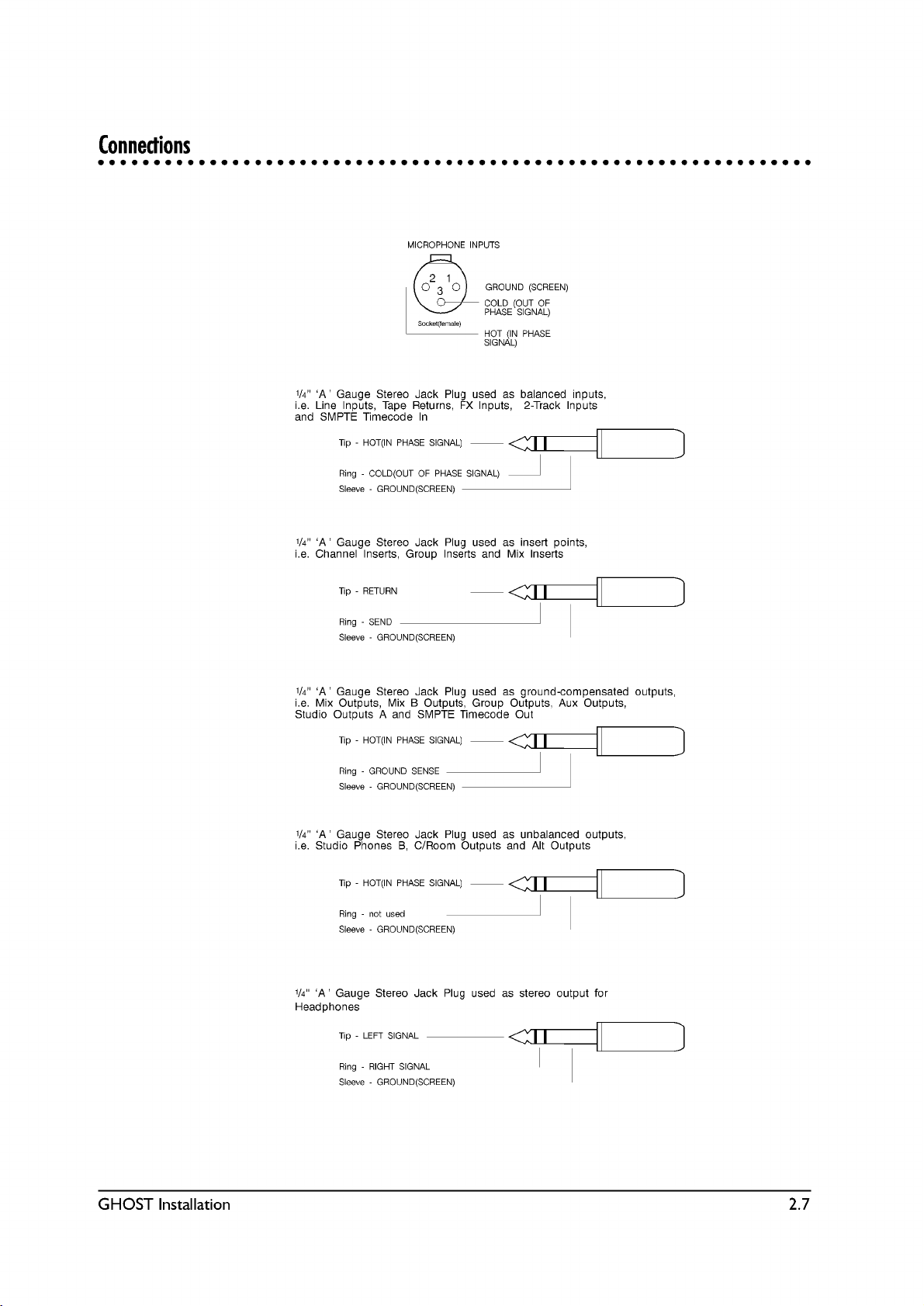
Connections 2.7
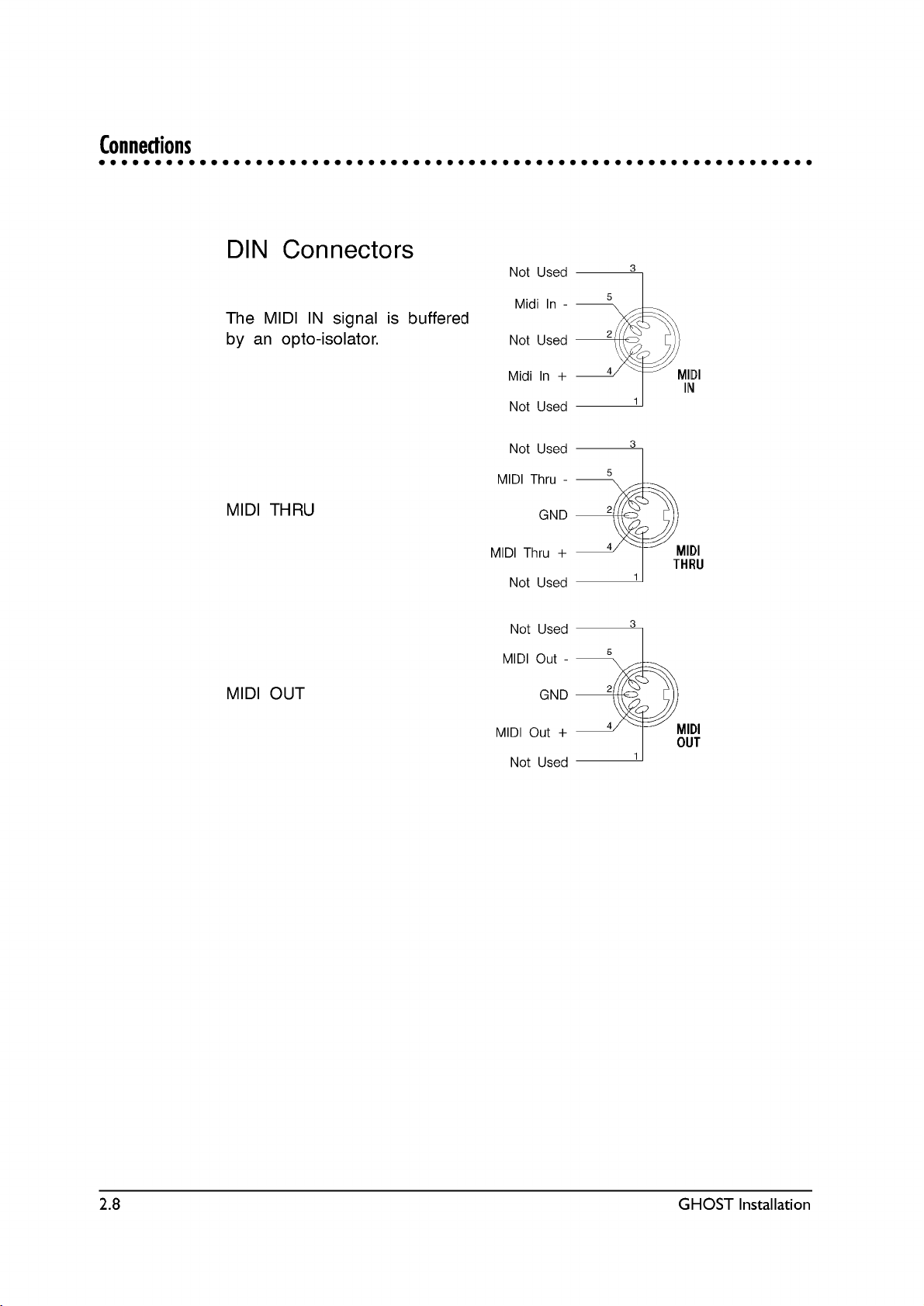
Din Connectors 2.8
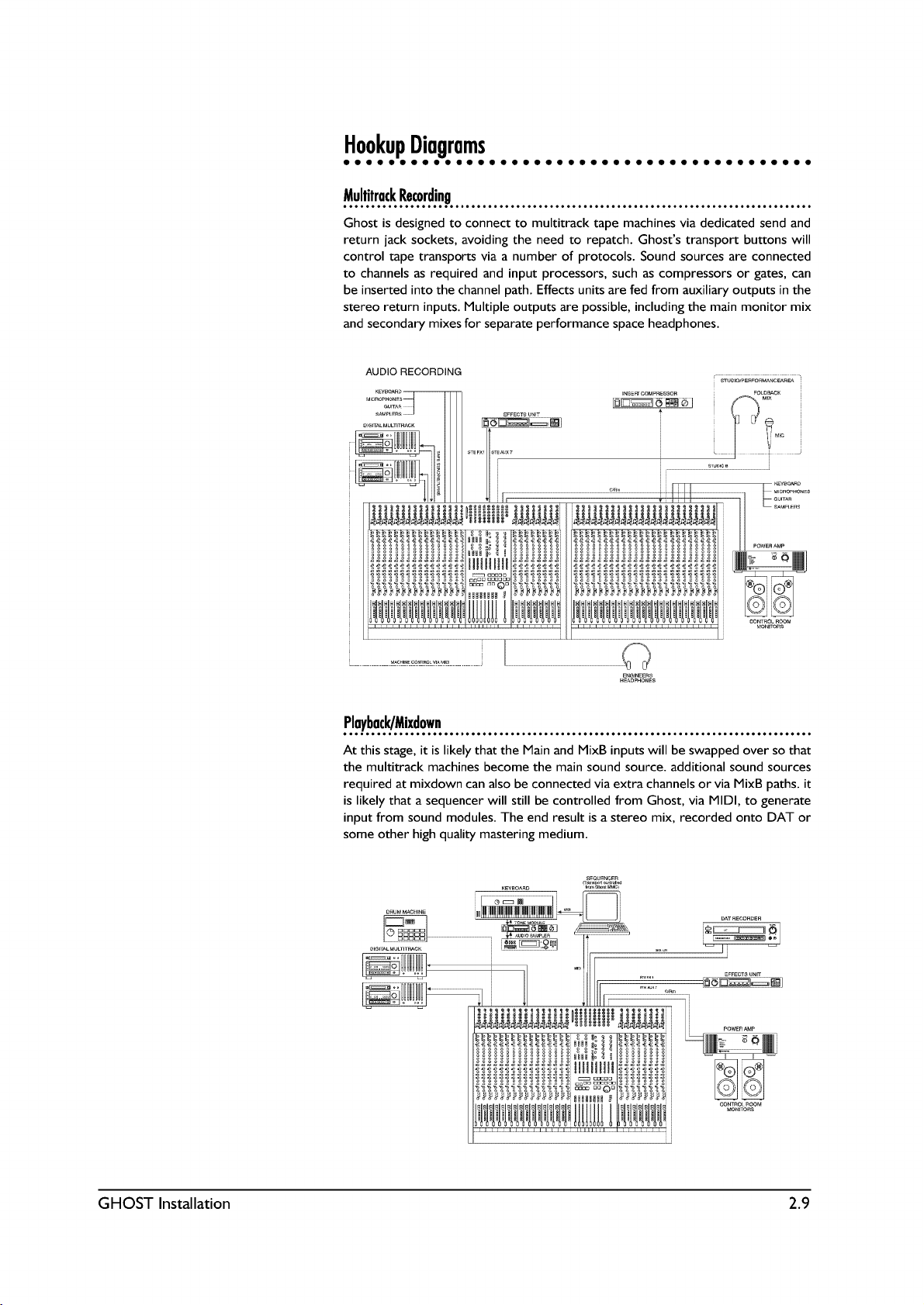
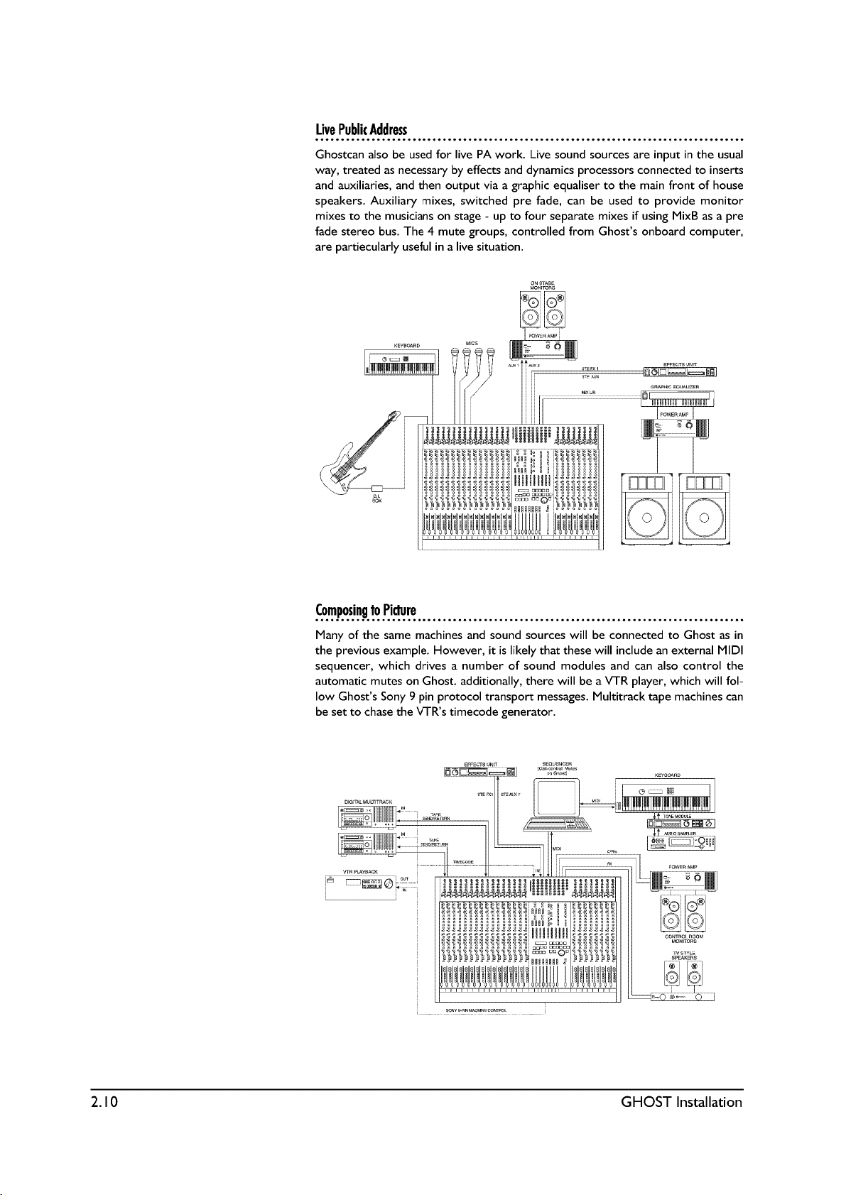
Hookup Diagrams 2.9
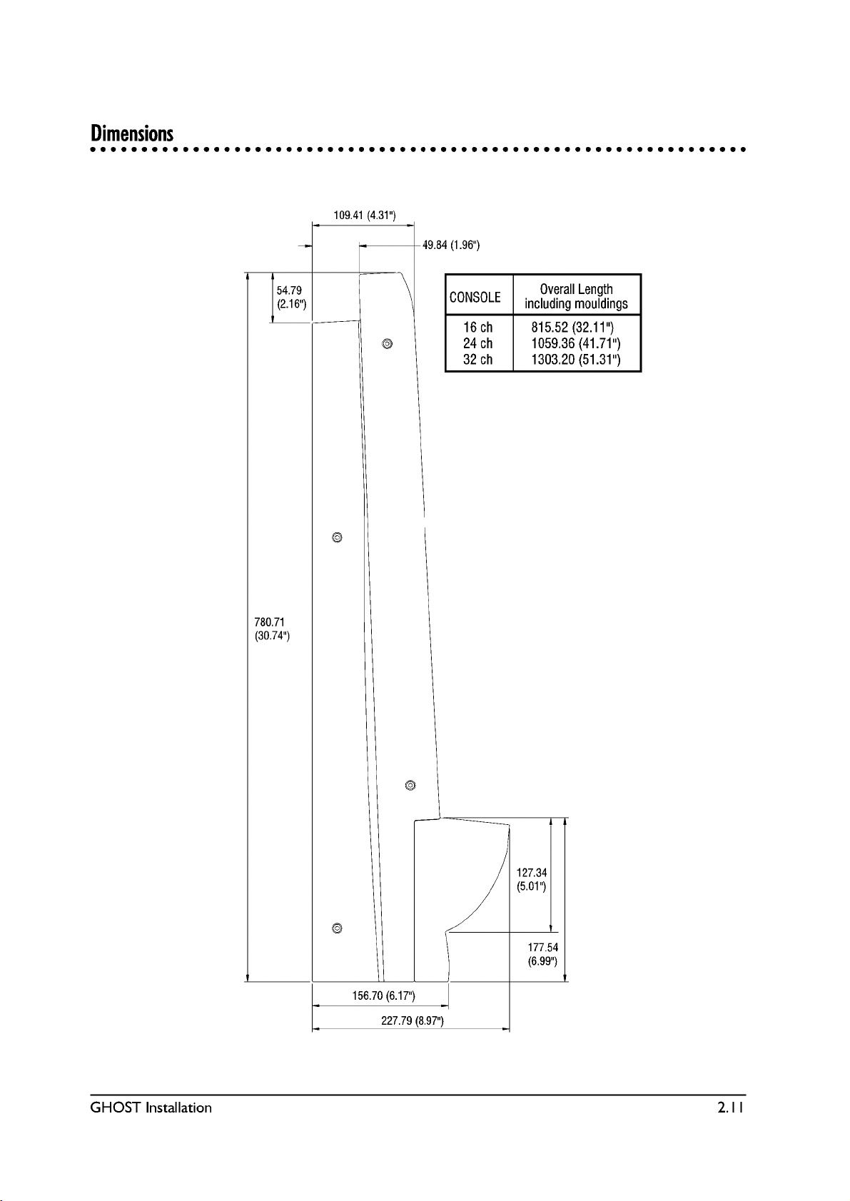
Dimensions 2.11
3 Quick Start Guide 3.1
Control Room Monitoring 3.6
Studio Monitoring 3.7
Adding Effects and Processors 3.9
4 Block Diagram 4.12
Block Diagram Explanation 4.3
Signal Flow 4.6
Overview of Main Signal Paths 4.12
5 Back and Rear Panel Description 5.1
Back Panel 5.2
6 Functional Description 6.1
The Mono Input Module 6.2
Output and Master section 6.15
7 Tutorial 7.1
Multitrack Tutorial 7.2
Studio Monitoring 7.8
GGHHOOSSTT
Page 4

ii GHOST Contents
8 Application Notes 8.1
Overview 8.2
9 CPU Application Guide 9.1
(NOT APPLICABLE TO GHOST LE)
10 Troubleshooting 10.1
General 10.2
Troubleshooting Chart 10.3
11 Specifications 11.1
12 Glossary 12.1
Appendix A A.1
Notes for Machine Control A.2
Appendix B B.1
MIDI Controller Numbers B.2
Appendix C C.1
MIDI Note Numbers to Mutes Conversion Chart C.2
MIDI Note Numbers to Expander Mutes Conversion Chart C.3
MIDI Note Numbers by Octave C.4
Appendix D D.1
MIDI Implementation Chart D.2
Appendix E E.1
Upgrading the Software E.2
Page 5

GHOST Introduction 1.1
GGHHOOSSTT
IInnttrroodduuccttiioonn
1
Page 6

1.2 GHOST Introduction
IInnttrroodduuccttiioonn
Thank you for purchasing the Soundcraft Ghost Music Production console. It has
been designed to give you many years of trouble-free service. Please read this
entire guide before using the console and then retain it for future reference. The
terms console, mixer, and board are used interchangeably throughout this guide.
This guide covers two versions of the Ghost console, namely Ghost (with a CPU
section containing a Timecode reader/generator, MIDI Machine Control, MIDI
Mute Automation, and MIDI Controller Faders) and Ghost LE (with no CPU sec-
tion). Both Ghost and Ghost LE are identical, except that Ghost LE does not have
a CPU section above the Group faders. The top panel views in this guide some-
times show Ghost and sometimes Ghost LE. Except for the sections dealing with
the CPU, which applies to Ghost only, everything else in this guide applies to both
Ghost and Ghost LE.
This guide is composed of a Table of Contents, 12 chapters, 5 appendices, and an
index. Following is an overview of the guide:
Chapter Title Description
- Table of Contents Allows you to find broad topics easily.
1 Introduction What you are currently reading.
Contains basic information about Ghost.
2 Installation Contains information about installing
Ghost and modifying some of its default
settings. Also has detailed hookup and
connections diagrams.
3 Quick Start Allows you to quickly get up and running
Guide with Ghost.
4 Block Diagram Contains a standard pictorial block diagram,
as well as a plain English signal flow explana
tion of that diagram.
5 Back and Rear Contains a detailed description of all of
Panel Description Ghosts back and rear
panel jacks.
6 Functional Contains a detailed description of all of
Description Ghosts controls.
7 Tutorial Explains in detail how to use Ghost for
tracking, overdubbing, monitoring, adding
effects and processors, punching in/out,
bouncing tracks, and mixing down.
8 Application Explains some of Ghosts more advanced
Notes uses.
9 CPU Application Explains how to use the CPU section of
Guide Ghost. (Not Applicable to Ghost LE.)
Page 7

GHOST Introduction 1.3
10 Troubleshooting Contains some common problems, causes,
and solutions.
11 Specifications Lists complete specifications of Ghost.
12 Glossary Contains some common audio terms and
their definitions.
- Appendices Contain information on MIDI Machine
A through E: Control, Controller Numbers, Note
Numbers, MIDI Implementation Chart, and
upgrading Ghosts software.
- Index Contains a detailed index, which allows
you to find a specific topic.
It is suggested that you read this entire manual. If youre the type that doesnt like
to read manuals, then we suggest the following:
For Advanced Users: Read the Introduction (up to "The Basics of In-Line
Consoles"), Installation, Block Diagram, Back and Rear Panel Description, and
Functional Description chapters, and the Appendices.
For Intermediate Users: Read the Introduction (up to "The Basics of In-Line
Consoles"), Installation, Quick Start Guide, Block Diagram, Back and Rear Panel
Description, Functional Description, and Application Notes chapters, and the
Appendices.
For Beginning Users: You should read the entire manual, but at the very least you
should read the entire Introduction, Installation, Block Diagram, Back and Rear
Panel Description, Functional Description, Tutorial, Application Notes chapters,
and the Appendices. Refer to the Troubleshooting and Glossary chapters, as need-
ed.
For All Users: If you have the Ghost console with the CPU (not Ghost LE), then
you should also read the CPU Application Guide chapter.
Page 8

1.4 GHOST Introduction
FFeeaattuurreess ooff GGhhoosstt aanndd GGhhoosstt LLEE
Ghost is a professional 8-bus mixing console, primarily designed for multitrack
recording and music production applications. It is an In-Line console, having a main
input path and a secondary Mix B input path on each channel. This doubles the
number of inputs at mixdown, yet the console remains compact. Following are
some of Ghosts features:
l Soundcrafts ProMic ultra-low-noise mic preamp, with +60dBu input sensi-
tivity, is included on every channel.
l Every channel features a mic input, a line input, individually switched
phatom power, mic/line switch, phase reverse, and 100Hz Low-Cut Filter.
l Multi-busing on every channel allows Direct Outs on each channel to also
be used as Group Outs, allowing you to send a signal from any channel to
any of 32 tape tracks (24 tape tracks with 24 channel Ghost).
l Powerful 4-band "British" EQ, featuring high/low shelving EQ and two fully-
parametric mid EQs, with continuously variable Q (bandwidth) control and
EQ In/Out switch.
l 6 mono (4 usable at once per channel) and 2 stereo auxiliary sends. Sends
1/2 are switchable as a pair between pre-fader and post-fader. Sends 3/4
can be routed as a pair to Sends 5/6.
l 100mm faders and inserts for channels, groups, and main L/R mix.
l Variable brightness Signal Present LED for each channel.
l Peak LED for each channel.
l Automated/Manual Mutes (Cut) for each channel. (Mutes cannot be auto-
mated on Ghost LE.)
l Solo (either PFL or Solo-in-Place) for each channel.
l Mix B section on each channel features a line input, source select (tape or
channel), rotary fader, pan, PFL Solo, and automated/manual Mutes (Cut).
(Mutes cannot be automated on Ghost LE.)
l Tape Input Trim pot for the Mix B line input.
l High/Low shelving EQ and Auxs 3/4 (5/6) may be switched into the Mix B
path.
l Reverse switch allows you to route the channel input to the Mix B path and
the Mix B input to the channel path.
l 8 Group buses with AFL solo and routing to the L/R bus.
l 4 stereo effects returns, each with PFL Solo and routing to the L/R bus or
any of the group buses.
l 2 separate Studio Foldback monitoring sections with AFL Solo.
l Control Room monitoring section with headphone jack, mono check, pro-
visions for two stereo line inputs (DAT deck, two-track deck, CD player,
etc.), and two sets of control room monitors.
l A 2-frequency oscillator.
l Talkback section with built-in mic.
l 8 Aux Send Master pots with AFL Solo.
Page 9
GHOST Introduction 1.5
l Mix B Master pot with provision for routing Mix B to the L/R bus.
l PFL/AFL Trim pot with Solo LED and Solo-in-place switch with LED.
l 12-segment vertical peak LED meters for the 8 Groups and for the Control
Room/Solo outputs.
l By using the channel inputs, Mix B inputs, and 4 stereo FX returns at mix-
down, you have a total of 56 inputs from the 24 channel Ghost and a total
of 72 inputs from the 32 channel Ghost.
l Optional 24 channel expander module is available.
l Optional meterbridge is available.
AAddddiittiioonnaall ffeeaattuurreess ooff GGhhoosstt ((NNoott FFoouunndd oonn GGhhoosstt LLEE))
l MIDI In/Out/Thru jacks.
l SMPTE timecode In/Out jacks and Sony 9-pin connector.
l SMPTE/MTC timecode reader/generator/converter.
l MIDI Machine Control transport control buttons with jog/shuttle wheel for
controlling external tape machines, video machines, hard disk recorders,
and MIDI sequencers.
l 4 mute groups.
l 128 snapshots for MIDI muting, which may be recalled manually, from
timecode, or from MIDI Program Change Messages.
l Dynamic Mute Automation (with an external MIDI sequencer).
l 4 MIDI Controller Faders for controlling external MIDI effects and other
MIDI parameters by transmitting MIDI Control Change data.
FFrraammee SSiizzeess && EExxppaannddeerr MMoodduullee
Ghost is available in two frames sizes:
l 24 Input Channels
l 32 Input Channels
There is also an optional 24 channel expander module available, which allows you
to expand Ghost to 48 channels or 56 channels. With the 4 stereo FX returns, this
will give you either 104 or 120 inputs at mixdown.
MMeetteerrbbrriiddggee
There is an optional meterbridge for each console size and for the expander mod-
ule. The meterbridge contains a vertical 12 segment peak LED meter for each
channel, which can be internally configured to show either the Mix B (tape) inputs
or the channel inputs. It also includes two
20-segment LED VU meters for the Control Room/Solo outputs.
PPoowweerr SSuuppppllyy
Use only the power supply that comes with the console and make sure it is config-
ured for the country you will be using it in.
Page 10

1.6 GHOST Introduction
CCoonnttaacctt IInnffoorrmmaattiioonn
You may write, phone, fax, or EMAIL Soundcraft at the following places:
In Europe:
Soundcraft Telephone: +44 (0) 1707 665000
Harman International Industries LTD. FAX: +44 (0) 1707 660742
Cranborne House, Cranborne Rd., EMAIL: info@soundcraft.co.uk
Potters Bar, Herts, EN6 3JN, UK.
In the United States:
Soundcraft USA Telephone: 1(615) 360-0471
1449 Donelson Pike FAX: 1(615) 360-0273
Nashville, Tennessee 37217
TThhee BBaassiiccss ooff IInn--LLiinnee CCoonnssoolleess
When using a console for traditional multitrack recording, it is necessary to be able
to record the consoles channel inputs to tape, while at the same time monitoring
previously recorded tape tracks. When youre finished recording, you must be
able to play the finished multitrack master tape through the console, make adjust-
ments to the tape tracks, and then record your mix to your 2-track mixdown
deck. This means that the outputs of the mixer (group outs or direct outs) have to
be connected to the inputs of the multitrack deck for recording purposes, while at
the same time the outputs of the multitrack deck have to be connected to the
inputs of the mixer (tape returns) for monitoring and mixdown purposes.
However, the requirements for simply monitoring tape tracks while overdubbing
are different than what is needed when mixing down those tracks.
Before in-line consoles, split console designs were used. Since this is not a primer
on split consoles, just the basics will be given here. With split consoles the channel
strips and the tape returns were split, with the channels on the left side and the
tape returns located above the group masters on the right side of the board. While
tracking and overdubbing, the channel outputs were routed to the multitrack
inputs and the multitrack outputs were routed to the tape returns. The channels
were used for recording and the tape returns were simply used to monitor previ-
ously recorded tape tracks. This meant that if you wanted to monitor 32 tape
tracks, you had to have 32 separate tape returns located apart from the channel
strips. And those returns might have only provided level and pan controls for each
track. Since the tape returns didnt offer all the features of the channel strip (such
as EQ and Aux Sends), and didnt provide a way to route the tape tracks to the
mixdown deck, when it came time for mixdown, the multitrack outputs had to be
repatched from the tape returns to the channel strip inputs. This allowed you to
use all of the features of the channel strip and to route the tape tracks to the
2-track deck during mixdown. While this is an oversimplification of the process, it
is sufficient to illustrate the point.
The drawbacks of a split console design are as follows: the console usually has to
be very wide to accommodate all the tape returns; as the number of tape returns
increases on a console, so do the number of channel strips, so if you need 32 tape
returns, you might have to buy a console with 64 or more channel strips; you have
to repatch when you want to mixdown and then repatch again when you want to
track and overdub; while mixing down, the tape returns are unused; and split con-
sole designs cost more than an equivalent in-line design.
An in-line console solves these problems, while remaining compact and affordable.
With todays digital multitrack recorders, hard disk recorders, and MIDI
sequencers, many studios have 24 or more tracks (whether tape, disk, or
sequenced) that need to be monitored, yet not as many channel inputs are needed
for recording purposes. With an in-line console, the tape return controls are physi-
cally located right in the channel strip, or "in-line" with the channel strip, hence,
Page 11

GHOST Introduction 1.7
the name. You have as many tape returns as you have channel strips, yet no extra
width is added to the console regardless of the number of returns, although there
is a slight increase in the depth of the console.
As mentioned, Ghost is an in-line console. There are 2 separate inputs for each
channel strip. The main channel input is called "Channel" and the tape return input
is called "Mix B." Note that you can connect any line level source to Mix B; it does-
nt have to be the output of a tape deck. Normally, whatever is connected to the
mic or line input on the rear panel is routed to the channel strip and you use the
channel strips controls to process that input. And whatever is connected to the
Mix B/Tape Ret jack on the rear panel is routed to the Mix B section, located with-
in the same channel strip, and you use Mix Bs controls to process the Mix B input
separately from the channel input.
Generally speaking, while recording basic tracks and overdubbing, you connect the
sources you want to record to the channel inputs and you connect the sources
you want to monitor to the Mix B inputs. Youll usually want to monitor previously
recorded tape tracks, hard disk tracks, and MIDI sequenced tracks. At mixdown,
youll press the Reverse switch on each channel, which will route the Mix B inputs
to the channel strip and the channel inputs to Mix B. Youll also be able to route all
of the Mix B outputs as a group to the L/R bus for mixdown to a 2-track recorder.
This is how you double the number of inputs at mixdown. By doing this, all of your
tape tracks are now routed to the channel strips, with the full complement of
channel strip controls available to the tape tracks for mixdown, while at the same
time allowing you to connect sources, such as MIDI tracks, that dont need as
much processing, to the Mix B inputs, which can also be recorded to the 2-track
deck. This means that Mix B, which is normally used as a tape return, can also be
used for recording during mixdown. In addition, Mix B has access to some of the
channel EQ and Aux Sends.
Complete descriptions of all the features, a Quick Start Guide, and a Tutorial fol-
low later in this guide.
Page 12

1.8 GHOST Introduction
Page 13
Page 14
Page 15
Page 16
Page 17
Page 18
Page 19
Page 20
Page 21
Page 22
Page 23
Page 24

Page 25
GHOST Quick Start Guide 3.1
GGHHOOSSTT
QQuuiicckk SSttaarrtt GGuuiiddee
3
Page 26
3.2 GHOST Quick Start Guide
QQuuiicckk SSttaarrtt GGuuiiddee
We suggest that you read this entire manual before using Ghost; but for those who
want to get started right away, we have provided this QUICK START GUIDE.
This will get you up and running quickly. The basic procedures given here are
taken from the TUTORIAL chapter, which contains much more detailed informa-
tion. If you dont understand something in this chapter, then refer to the TUTORI-
AL. However, to get the full benefit of Ghosts many features, it is suggested that
at some point you read this entire manual.
RReeccoorrddiinngg BBaassiicc TTrraacckkss ((TTrraacckkiinngg))
Procedure:
1.
Reset Console. "Zero Out" or reset the console. That means to set all
controls to their off or neutral positions.
2. Connections. Connect your input sources to the channel MIC and LINE
inputs.
3. Select Inputs. Use the MIC/LINE switch to select the appropriate input
for each channel. Press the 48V switch for condenser mics, where
required. Make sure the REV switch is not depressed.
4. Recording methods. There are 3 methods you can use to send the chan-
nel signal to a multitrack tape recorder (MT), and they are outlined below:
a. Using the Group Output jacks. Use this method if the GRP 1-8 output
jacks are connected to the inputs of your multitrack recorder. The group
number should match the tape input number. In the channel strip, press the
assign switch for the tape track(s) you want to record on. Next, use the
pan pot to send the signal to the Group output jack for the track(s) you
wish to record on. Pan left for odd-numbered tracks; right for even-num-
bered tracks; and centre for both tracks. Then, turn up the channel fader
to its nominal position, as indicated by the fader marking 3/4 of the way up.
Finally, turn up the appropriate Group fader(s) to its nominal position.
b. Using the DIR/TAPE SND jack as a Group Output. Use this method if
the DIR/TAPE SND jacks are connected to the inputs of your multitrack
recorder, and you wish to use the Groups for recording. The channel num-
ber should match the tape input number.
First, press the DIR/GRP n switch (on the rear connector panel) on the
channel that represents the tape track you wish to record on. Then note
the GRP n number on the switch. For instance, both channels 2 and 10 will
have a switch that reads DIR/GRP 2. This means that the channel 2 and
channel 10 DIR/TAPE SND jacks will act as Group 2 output jacks, when
their DIR/GRP 2 switches are pressed.
Next assign all the inputs youre recording to the appropriate Group num-
ber(s) and use the pan pot to send the signal to the appropriate Group bus.
Pan left for odd-numbered groups; right for even-numbered groups; and
centre for both groups.
Then, turn up the channel fader to its nominal position, as indicated by the
fader marking 3/4 of the way up. Finally, turn up the Group fader(s) to its
nominal position.
c. Using the DIR/TAPE SND jack as a Direct Output: Use this method if the
DIR/TAPE SND jacks are connected to the inputs of your multitrack
recorder, and you wish to record directly from the channel outputs. The
channel number should match the tape input number.
Page 27

GHOST Quick Start Guide 3.3
This method differs from method (b), above, because youre using the
DIR/TAPE SND jack as a Direct Output from the channel and the Group
buses are not involved at all. The channel signal, post-fader and post-mute,
will be routed to this jack for direct recording to your multitrack.
To use this method, first make sure the DIR/GRP n switch (on the rear con-
nector panel) is in the DIR (UP) position for all channels that you wish to
record. Then, turn up the channel fader to its nominal position, as indicated
by the fader marking 3/4 of the way up. The pan pot and assign switches will
have no effect on the Direct Output signal.
Select one of the above three recording methods and then proceed to step 5.
5. Setting Up The MT. On the MT, insert a tape, wind to where you wish to
begin recording, set the counter to zero, put the appropriate tracks into
RECORD-READY mode, and set the recording level controls of the MT, if
any, to their nominal positions.
6. Monitoring. To learn how to listen to the sound you are recording, see the
section below entitled, "Control Room Monitoring." To learn how to send the
sound you are recording to the musicians in the studio, see the section below
entitled, "Studio Monitoring."
With the musicians playing, set up preliminary monitor mixes for the Control
Room and Studio.
7. Gain Structure. If you have the optional meterbridge and its set for channel
input monitoring, then gradually turn up the Input Sensitivity knob until the
meterbridge channel input meter indicates 0.
In all other instances, press the channel SOLO switch. Make sure the SIP
switch in the master section is off. This will display the channel signal on the
CRM/SOLO-L/R meters in the master section. Gradually turn up the Input
Sensitivity knob until the meters indicate 0, then turn the SOLO switch off.
In either case, the Signal Present LED should be brightly lit, and the PK LED
should light only occasionally, if at all.
8) LCF & Phase. Use the Low-Cut Filter (LCF) switch to get rid of low fre-
quency noise. The Phase switch should be in the up position, unless you
know your input cables are wired incorrectly or if youre employing M-S
recording techniques.
9. EQ. If you want to add EQ to the channel inputs, first press the EQ IN switch
and make sure the EQ MIX B button is up. Then apply the EQ as needed.
The HF/LF shelving EQ can be boosted or cut 15dB. The HMF/LMF EQ are
true parametrics and allow you to select the centre frequency, the bandwidth
of that frequency (with the Q control), and apply boost or cut of 15dB.
10. Effects & Processing. If you want to add effects or processing, then see the
section below, entitled, "Adding Effects and Processors."
11. Adjust Faders. Adjust the channel and group faders, as required, so that the
multitracks meters display the desired recording level.
12. Recording. Set up your final monitor mixes, and then have the musicians
stop playing. Put the MT into RECORD mode and have the musicians play the
song. When the song is over, STOP the multitrack and rewind the tape to
zero.
13. Playback. Play back the tracks you have just recorded. To let the musicians
in the Studio hear the take, select CRM as the Source in the appropriate
Studio Foldback section.
Page 28

3.4 GHOST Quick Start Guide
14. Record Another Take. If dissatisfied, record over the first take or add
another take after it. Before recording again, remember to unselect CRM
and select AUX 1-2 as the Studio Foldback Source, if necessary.
15. Proceed With Overdubbing. When you are satisfied with the take of the
basic tracks, you can proceed to "Overdubbing," below.
OOvveerrdduubbbbiinngg
Procedure:
1. Tape Channels. On all channels that contain the outputs of previously
recorded tape tracks, press the REV switch and set the MIX B SRCE switch
to CHAN. This routes the Tape Returns to both the Channel and MIX B
paths. These are your Tape channels and are for monitoring purposes only.
2. Connections. Connect your input sources for the overdub to the channel
MIC and LINE inputs. Do not connect them to any Tape channels. These
are your Input channels.
3. Select Inputs. On the Input channels, use the MIC/LINE switch to select
the appropriate input for each channel. Press the 48V switch for condenser
mics, where required. Make sure the REV switch is not depressed and set
the MIX B SRCE switch to TAPE.
4. Select Recording Method. Select one of the 3 recording methods, from
above, and follow the directions for signal routing and channel/group fader
positioning for each Input channel.
5. Setting Up The MT. On the MT, rewind the tape to the beginning of the
song, or to a point before the overdub will be recorded, set the counter to
zero, and put the appropriate track(s) into RECORD-READY mode. Make
sure that all previously recorded tracks are not in RECORD-READY mode.
Then set the recording level controls of the MT, if any, to their nominal
positions and start playing the tape.
6. Monitoring And Gain Structure. With the musicians playing along with
the tape, set up Control Room and Studio preliminary monitor mixes of the
overdub being recorded and of previously recorded tape tracks. (See
Control Room/Studio Monitoring, below.) Then use the INPUT SENSITIVI-
TY knob to set your input gain structure for the overdub, using the optional
meterbridge or the CRM/SOLO-L/R meters, and the SIG and PK LEDs.
(See "Recording Basic Tracks," above.)
7. LCF & Phase. Use the LCF and PHASE switches, as required. (See above.)
8. EQ. Apply EQ, as required. (See above.)
9. Effects & Processing. If you want to add effects or processing, then see
the section below, entitled, "Adding Effects and Processors."
10. Adjust Faders. Adjust the channel and group faders, as required, so that
the multitracks meters display the desired recording level.
11. Recording. Set up your final monitor mixes, of both the live signal and of
previously recorded tape tracks, and then have the musicians stop playing.
Put the MT into RECORD mode and have the musicians play the overdub.
When the overdub is over, STOP the multitrack and rewind the tape to
zero or to a point right before the overdub.
12. Playback. Play back the overdub you have just recorded. To let the musi-
cians in the Studio hear the take, select CRM as the Source in the appropri-
ate Studio Foldback section.
Page 29

GHOST Quick Start Guide 3.5
13. Record Another Take. If dissatisfied, record over the first take of the
overdub. Before recording again, remember to unselect CRM and select
AUX 1-2 as the Studio Foldback Source, if necessary.
14. Proceed With Overdubs & Mixing Down. When you are satisfied with
the take of the overdub, proceed to record the next overdub. When youre
satisfied with all the tracks on the tape, you can proceed to "Mixing Down",
below.
MMiixxiinngg DDoowwnn
Procedure:
1. Inputs. "Zero Out" the console and then press the REV switches to route
all your tape tracks to the channel path. Channel inputs on those channels
will be routed to the MIX B path. If you have additional input sources, such
as MIDI tracks, and extra channels available (that are not being used for
tape tracks), then route the additional sources to the channel path. If you
have more input sources than channels, then connect some to the channel
inputs and some to the MIX B inputs. Then decide where best to route
those extra sources, between the channel and MIX B paths. You can also
use the Effects Returns as line level source inputs, but remember that youll
probably also need inputs for the outputs of your effects devices. Make
sure the MIX B SRCE switch is set to TAPE (UP) on all channels, unless you
wish to use it as a pre-fader send for the channel path.
2. Assignment & Master Levels. Assign all channels and Effects Returns that
are in use to the L/R MIX by pressing the L/R assign switch on the channels
and the MIX assign switch on the Effects Returns. Press the MIX B TO MIX
switch in Ghosts MIX B master section and set the MIX B rotary master
fader about 75% up. Set the MIX L/R master fader to the top of its travel.
3. Using Groups. If youre grouping some sources, assign them to the appro-
priate Group buses and then assign the Group buses to the L/R MIX, using
the TO MIX- L, R, and L+R switches in the Group master section. Turn
the appropriate Group faders about 75% up.
4. Monitoring. Set the CRM SRCE to monitor MIX A only, turn up the level
control, and make sure MONO CHECK is off. To send the mix to the stu-
dio, select CRM as the source in the appropriate Studio Foldback section
and turn up its level control.
5. Input Gain. Adjust the INPUT SENSITIVITY and TAPE TRIM knobs, if
needed. (See above.)
6. Setting Up The MT. Rewind the MT tape, set the counter to zero, and
start playback. If the MT has an output level control, set it to its nominal
position. If youre syncing a sequencer to the tape, make sure its set up
properly, so that the MIDI tracks are also playing.
7. Practice The Mix. As the tape plays, set the relative levels of the
tape/MIDI tracks using the channel and MIX B faders, (and the FX level
controls, if they are being used as inputs). Use the PAN and BAL controls
to set the stereo perspective. USE EQ, effects, and processors, as needed.
(See "Effects and Processors," below.) Use the MUTE Automation system,
as needed. (Not Ghost LE). (See the "CPU Application Guide" in this manu-
al.) Use the MONO CHECK switch periodically to check for mono com-
patibility. Listen to the mix through your main speakers, your alternate
speakers, if any, and headphones. Keep practicing the mix, until youre
happy with it, then rewind the MT tape to the beginning of the song.
Page 30

3.6 GHOST Quick Start Guide
8. Setting Up The 2-Track. Insert a new tape in your 2-track recorder and
rewind it to the beginning. Roll about one minute into the tape and use the
TO TAPE switches in the Talkback and Oscillator sections to record any
announcements and tones that are needed. Allow the tape to roll a bit past
the tones, stop the 2-track, and set the counter to zero. Then, set the deck
to RECORD-READY mode and set its input level control to its nominal
position.
9. Setting Levels. Play the MT tape again, and adjust the MIX L/R Master
fader, MIX B Master fader, and Group Master faders, to retain the proper
balance of your mix, while at the same time, achieving the proper level on
your 2-track recorders meters. The proper recording level should be
achieved with the 2-tracks input control at its nominal position. Then
rewind the MT tape to the beginning of the song.
10. Recording The Mix. To commit your final mix to tape, start the 2-track in
RECORD mode and then start playback of the MT tape. Make any mix
moves that are necessary and when the song is completed, stop the 2-
track, then stop the MT. Press the appropriate 2-TK switch in the CRM
SRCE section, unselect MIX A, and then rewind and play back the 2-track
tape. If youre not satisfied with the final mix, then unselect the 2-TK CRM
SRCE switch, select MIX A, and try the mix again. If you are satisfied with
the mix, then make a dub of the 2-track master and play the dub on as
many systems as you can. If youre not satisfied, then mix it again. If the mix
meets with your approval on these other systems, then make a backup
copy of the 2-track master and label everything. This final 2-track stereo
master tape is now ready for mastering and/or duplication.
Page 31

GHOST Quick Start Guide 3.7
CCoonnttrrooll RRoooomm MMoonniittoorriinngg
CCRRMM SSiiggnnaall MMoonniittoorriinngg
Procedure:
1. Follow the procedures under "Recording Basic Tracks" to send your live
signals to the MT for recording.
2. On Ghost, make sure all CUT and SOLO/PFL/AFL switches are off, and
that the REV switch is OFF (UP) in the MIX B channel(s) you will use for
monitoring.
3. On the MT, press the RECORD-READY switches for the track(s) you wish
to record on and set the record level control, if any, to its nominal position.
4. In the CRM SRCE section, make sure that only MIX B is pressed and that
MONO CHECK is off. Turn the CRM LEVEL knob about 75% up.
5. Turn the MIX B master fader in Ghosts master section about 75% up.
6. On the appropriate MIX B section that corresponds to the track you are
recording on, make sure the SRCE switch is set to monitor TAPE (UP
Position).
7. With the performers playing their parts, (there should be a reading on the
MTs meters for the track(s) you are recording), adjust the TAPE TRIM
knob in the appropriate channel strips input section, if necessary. Then
turn up the appropriate MIX B level control to attain the volume you want
and use its pan pot to determine the stereo placement. You will now be
monitoring all signals sent to the appropriate tape track.
8. The Channel faders, Group faders (if youre recording with the Group
buses), TAPE TRIM knob, MIX B master fader, MIX B level control, CRM
LEVEL knob, and the MT record level control, if any, will all affect the vol-
ume of the monitored signal.
CCRRMM TTaappee MMoonniittoorriinngg
Procedure:
1. On Ghost, make sure all CUT and SOLO/PFL/AFL switches are off, and
that the REV switch is ON (Down) in the MIX B channel(s) you will use for
monitoring tape playback.
2. In the CRM SRCE section, make sure that only MIX B is pressed and that
MONO CHECK is off. Turn the CRM LEVEL knob about 75% up.
3. Turn the MIX B master fader in Ghosts master section about 75% up.
4. On the appropriate MIX B section that corresponds to the tape track you
wish to monitor, make sure the SRCE switch is set to monitor CHAN
(DOWN Position). You are really monitoring TAPE, since the channel and
MIX B paths have been reversed.
5. Set the output level control on the MT, if any, to its nominal position, and
with the MT tape playing, adjust the TAPE TRIM knob in the channel strips
input section, if necessary. Then turn up the appropriate MIX B level con-
trol to attain the volume you want and use its pan pot to determine the
stereo placement. You will now be monitoring the tape playback of the
appropriate track.
6. The TAPE TRIM knob, MIX B master fader, MIX B level control, CRM
LEVEL knob, and the MT output level control, if any, will all affect the vol-
ume of the monitored signal.
Page 32

3.8 GHOST Quick Start Guide
SSttuuddiioo MMoonniittoorriinngg
SSttuuddiioo SSiiggnnaall MMoonniittoorriinngg
Procedure:
1. Follow the procedures under "Recording Basic Tracks" to send your live
signals to the MT for recording.
2. On Ghost, make sure all CUT and SOLO/PFL/AFL switches are off, and
that the REV switch is OFF (UP) in the channel(s) that you are going to
monitor.
3. In the STUDIO FOLDBACK section, decide whether you are using STU-
DIO A or STUDIO B/PHONES and make sure that only AUX 1-2 is
pressed. Turn the STUDIO LEVEL knob about 75% up.
4. Turn the AUX 1 and AUX 2 master fader pots in Ghosts master section
about 75% up and make sure their AFL switches are off.
5. On the appropriate channels that correspond to the channel inputs you are
about to record, make sure the AUX 1-2 PRE switches are depressed, so
that you are monitoring Pre-Fader.
6. With the performers playing their parts, turn up the AUX 1-2 level con-
trols, on all channels whose signals you want to monitor, to attain the vol-
ume (and balance) you want. AUX 1 will be sent to the left headphone
(speaker) and AUX 2 will be sent to the right headphone (speaker). You
will now be monitoring all channel input signals.
7. The AUX 1-2 master faders, AUX 1-2 level controls, and STUDIO LEVEL
knob, will all affect the volume of the monitored signal.
SSttuuddiioo TTaappee MMoonniittoorriinngg
Procedure:
1. On Ghost, make sure all CUT and SOLO/PFL/AFL switches are off, and
that the REV switch is ON (Down) in the channel(s) you will use for moni-
toring tape playback.
2. In the STUDIO FOLDBACK section, decide whether you are using STU-
DIO A or STUDIO B/PHONES and make sure that only AUX 1-2 is
pressed. Turn the STUDIO LEVEL knob about 75% up.
3. Turn the AUX 1 and AUX 2 master fader pots in Ghosts master section
about 75% up and make sure their AFL switches are off.
4. On the appropriate MIX B sections that correspond to the tape tracks you
wish to monitor (in the control room), make sure the SRCE switch is set to
monitor CHAN (DOWN Position). You are really monitoring TAPE, since
the channel and MIX B paths have been reversed. This has no effect on
Studio Tape Monitoring, but must be done in order to use MIX B for CRM
Tape Monitoring.
5. On the appropriate channels that correspond to the tape tracks you wish
to monitor, make sure the AUX 1-2 PRE switches are depressed, so that
you are monitoring Pre-Fader.
6. Set the output level control on the MT, if any, to its nominal position, and
with the MT tape playing, adjust the TAPE TRIM knob in the appropriate
channel strips input section, if necessary. Then turn up the AUX 1-2 level
controls, on all channels that correspond to the tape tracks you want to
monitor, to attain the volume (and balance) you want. AUX 1 will be sent
Page 33

GHOST Quick Start Guide 3.9
to the left headphone (speaker) and AUX 2 will be sent to the right head-
phone (speaker). You will now be monitoring the tape playback of the
appropriate tracks.
7. The TAPE TRIM knob, AUX 1-2 master faders, AUX 1-2 level controls,
STUDIO LEVEL knob, and the MT output level control, if any, will all affect
the volume of the monitored signal.
MMoonniittoorriinngg SSuummmmaarryy
To sum up, if tracks 1 and 2 were already recorded and you were currently
recording on track 3 through the channel 10 input, then for control room moni-
toring, you would use the MIX B sections of channels 1 and 2 to monitor the tape
playback of tracks 1 and 2, and you would use the MIX B section of channel 3 to
monitor what you were currently recording to track 3. For studio monitoring, you
would use AUX 1-2 of channels 1 and 2 to monitor the tape playback of tracks 1
and 2, and you would use AUX 1-2 of channel 10 (where the input is located) to
monitor what you were currently recording to track 3.
Page 34

3.10 GHOST Quick Start Guide
AAddddiinngg EEffffeeccttss aanndd PPrroocceessssoorrss
1. External Treatment. With this method you alter the signal before it
reaces Ghost. It is commonly used by guitarists, when using "stomp boxes."
For example, you connect a guitar cable to the input of a delay box, then
you connect the output of the box to one of Ghosts LINE inputs. You use
the effects mix control to determine the balance of wet and dry signals that
enters Ghost. External treatment does not require using any of Ghosts
controls. You simply plug the treated signal into one of Ghosts inputs.
2. Using Processors. Outboard processors are connected to Ghost using a
send/return Y-cable connected to one of Ghosts Insert jacks. The signal
from Ghost is sent to the outboard device, processed, and then the
processed signal is returned to Ghost. You use this method when you want
to treat the entire signal, as opposed to blending the wet and dry signals.
Youll generally use outboard EQ or dynamics processors with the Inserts.
Ghost has Inserts on all Channels, Groups, and the L/R Mix. Using proces-
sors with Ghost just requires that you connect them properly to Ghosts
Insert jacks. It does not require using any of Ghosts controls.
3. Using Effects. To use effects with Ghost, you can use the AUX system.
This method involves sending a copy of a channel/MIX B signal to the out-
board effect, processing it, and then returning it to Ghost. This wet signal is
then combined with the dry signal within Ghost.
NNoottee aabboouutt SSttuuddiioo MMoonniittoorriinngg aanndd EEffffeeccttss
The FX Returns were designed to add effects during mixdown, or while multi-
tracking in the control room and only using the control room monitor section.
When using the FX Returns, you cannot monitor the wet signal in the Studio
Foldback sections. However, you can record the wet signal to the multitrack or
the mixdown deck and you can monitor it in the Control Room. If youre record-
ing the effect and the performers dont care if they hear the effect while perform-
ing, then you can use the FX Returns. However, if the performers want to hear
the effect while recording, or if you want to record dry, but monitor wet, then
you should not use the FX Returns. You should connect the stereo outputs of
your effects device to 2 channel inputs and use those channels to route the wet
signal to the Group or L/R buses for recording, if desired, and to the Control
Room and Studio monitoring sections.
For connecting effects devices to the FX Returns. Studio Monitoring is not
possible
Procedure:
1. First, select which AUX Send you wish to use, based on whether you wish
to use it with a Channel or MIX B input and whether your effect has mono
or stereo inputs. Lets say you want to use AUX 1. (If you use AUX 1 or 2,
make sure the PRE switch is not pressed.) Connect the AUX 1 output jack
to the input of your effects device. Connect the L/R outputs of your effects
device to the FX 1-L/R jacks. (Note that you can use any FX RETURN.)
2. On the effects device, set the input level and output level controls to their
nominal positions. Make sure the effects unit is set for 100% wet output
and select the effect you wish to use.
3. Turn the AUX 1 rotary master fader control about 75% up. With a signal
present, turn the AUX 1 Send controls about 75% up on all channels that
you wish to be treated with the effect. This sends the channel signals to the
effects device.
Page 35

GHOST Quick Start Guide 3.11
4) There should be a reading on the input meter of the effects device, showing
that there is a signal present. If youre recording to a multitrack deck, then
set the Control Room Source to MIX B. If youre mixing down, then set the
Control Room Source to MIX A. Turn the Control Room Level knob 75%
up. You cannot monitor the effect in the Studio Foldback sections.
5. Use the Channel ASSIGN switches and PAN Pots to route the dry signals to
the appropriate buses, as usual. Use the FX 1 ASSIGN switches and BAL
knob to route the wet signal to the appropriate buses. You can record the
wet signal on the same tape tracks as the dry signals or on their own tape
tracks. Turn the appropriate Group Faders about 75% of the way up (if mul-
titracking) and set the MIX fader to the top of its travel (if mixing down).
This sends the wet and dry signals to the buses.
6. In the control room, to monitor the effect while youre recording to a multi-
track deck, you use the MIX B section in the channel strip that represents
the tape track the effect is being recorded on. To monitor the effect while
mixing down, you should assign the FX Return to the L/R Mix by pressing the
MIX switch, and then monitor MIX A in the control room, as usual. To
record dry and monitor wet, assign the FX Return to the L/R Mix by pressing
the MIX switch, but dont assign it to the Groups. Set the Control Room
Source to monitor both MIX A and MIX B. MIX B is what you normally use
for control room monitoring and MIX A would be used to monitor the
effect.
7. Turn the FX 1 level control about 75% up. This returns the wet signal from
the effects device to Ghost.
8. With a signal present in the channels youre using, you should be able to hear
the effect. Adjust the AUX 1 Send controls to determine how prevalent the
effect will be for each channel. For instance, all other things being equal, if
the AUX 1 Send control is turned 75% up for one channel and 50% up for
another channel, you will hear the effect more for the former channel.
9. After setting the AUX 1 Send levels for all the channels, press the AUX 1
Master Fader AFL switch. This will send all AUX 1 levels, post-AUX 1 mas-
ter fader, to the CRM/SOLO-L/R meters. Adjust the AUX 1 Master Fader so
that the meters read 0, then turn AFL off.
10. Adjust the input level of the effects device to achieve the meter reading on
the effects device, suggested by the devices manual.
11. Then press the PFL switch in the FX 1 section. This will display the effects
signal returned to Ghost, pre-FX 1 level control, on the CRM/SOLO-L/R
meters. Adjust the output level of the effects device so that the meters read
0, then turn PFL off.
12. Finally, adjust the FX 1 level control, together with the channel faders, to
achieve the blend of wet/dry signals that you desire. The channel faders con-
trol the dry signal and the FX 1 level knob controls the wet signal. The
Group/MIX faders control the overall signal sent to the Group/MIX buses.
Remember that the individual AUX 1 Send knobs and AUX 1 master fader
determine the level of the signal sent to the effects device and the FX 1 level
knob determines the level of the signal returned to Ghost.
Page 36

3.12 GHOST Quick Start Guide
For connecting effects devices to 2 Channel LINE Inputs (Channel
Returns).
Studio Monitoring is possible.
Procedure:
1. First, select which AUX Send you wish to use, based on whether you wish
to use it with a Channel or MIX B input and whether your effect has mono
or stereo inputs. Lets say you want to use AUX 1. (If you use AUX 1 or 2,
make sure the PRE switch is not pressed.) Connect the AUX 1 output jack
to the input of your effects device. Connect the L/R outputs of your effects
device to any 2 adjacent Channel LINE inputs. Make sure their REV switch-
es are not engaged and set their MIX B SRCE switches to CHAN (Down).
2. On the effects device, set the input level and output level controls to their
nominal positions. Make sure the effects unit is set for 100% wet output
and select the effect you wish to use.
3. Turn the AUX 1 rotary master fader control about 75% up. With a signal
present, turn the AUX 1 Send controls about 75% up on all channels that
you wish to be treated with the effect. This sends the channel signals to the
effects device.
4. There should be a reading on the input meter of the effects device, show-
ing that there is a signal present. If youre recording to a multitrack deck,
then set the Control Room Source to MIX B. If youre mixing down, then
set the Control Room Source to MIX A. Turn the Control Room Level
knob 75% up. For multitrack recording, select AUX 1-2 as the Studio
Foldback Source and turn its level control 75% up.
5. Use the Channel ASSIGN switches and PAN Pots to route the dry signals
to the appropriate buses. If you want to record the wet signal, then using
the Channel Returns, set their ASSIGN switches and PAN Pots to route the
wet signals to the appropriate buses. You can record the wet signals on the
same tape tracks as the dry signals or on their own tape tracks. Turn the
appropriate Group Faders about 75% of the way up (if multitracking) and
set the MIX fader to the top of its travel (if mixing down). This sends the
wet and dry signals to the buses.
6. In the control room, to monitor the effect while youre recording to a mul-
titrack deck, you use the MIX B section in the channel strip that represents
the tape track the effect is being recorded on. To monitor the effect while
mixing down, you should assign the Channel Returns to the L/R Mix by
pressing the L/R switch, and then monitor MIX A in the control room, as
usual. To record dry and monitor wet, dont assign the effect to the Groups
and use the MIX B sections in the Channel Returns to monitor the effect.
7. Set the Channel Return Faders to their nominal positions. This returns the
wet signal from the effects device to Ghost.
8. With a signal present in the channels youre using, you should be able to
hear the effect. Adjust the AUX 1 Send controls to determine how preva-
lent the effect will be for each channel. For instance, all other things being
equal, if the AUX 1 Send control is turned 75% up for one channel and
50% up for another channel, you will hear the effect more for the former
channel.
9. To send the effect to the performers in the Studio, whether or not you are
recording the effect, use the AUX 1-2 Sends on the Channel Returns.
These AUX 1-2 controls should be set up as Pre-Fader Sends by pressing
the PRE switch.
Page 37

GHOST Quick Start Guide 3.13
10. After setting the AUX 1 Send levels for all the channels, press the AUX 1
Master Fader AFL switch. This will send all AUX 1 levels, post-AUX 1 mas-
ter fader, to the CRM/SOLO-L/R meters. Adjust the AUX 1 Master Fader
so that the meters read 0, then turn AFL off.
11. Adjust the input level of the effects device to achieve the meter reading on
the effects device, suggested by the devices manual.
12. Then press the SOLO switches (with SIP Off) in the Channel Returns. This
will display the effects signal returned to Ghost, pre-channel fader, on the
CRM/SOLO-L/R meters. Adjust the output level of the effects device so
that the meters read 0, then turn SOLO off.
13. Finally, adjust the Channel Faders and Channel Return Faders for the wet
and dry signals, to achieve the wet/dry recording mix that you desire.
Adjust the MIX B level controls and AUX 1-2 Sends to achieve the wet/dry
monitoring mix that you desire for the control room and studio, respective-
ly. The Channel Faders that contain the signal sources control the dry signal
and the Channel Return Faders control the wet signal. The Group/MIX
faders control the overall signal sent to the Group/MIX buses. The MIX B
controls are used for control room monitoring and the AUX 1-2 controls
are used for studio monitoring. Remember that the individual AUX 1 Send
knobs and AUX 1 master fader determine the level of the signal sent to the
effects device and the 2 Channel Return Faders determine the level of the
signal returned to Ghost.
Page 38

3.14 GHOST Quick Start Guide
Page 39

GHOST Block Diagram 4.1
GGHHOOSSTT
BBlloocckk DDiiaaggrraamm
4
Page 40

4.2 GHOST Block Diagram
BBlloocckk DDiiaaggrraamm
PAN
L-R
1-2
3-4
5-6
7-8
AUX 7
(STEREO)
AUX 8
(STEREO)
AUX 1
AUX 3
PRE
MON
AUX 2
AUX 4
MIX B
FADER
CUT
PFL
PAN
5-6
LEFT
RIGHT
CUT
SOLO CUT
SOLO DETECT
PFL DETECT
PFL/AFL L
PFL/AFL R
AUX 1
GRP 1
GRP 2
GRP 3
GRP 4
GRP 5
GRP 6
GRP 7
GRP 8
GRP O/P BUS (1-8)
CPU MUTE BUS A
CPU MUTE BUS B
MIX L
MIX B L
MIX R
MIX B R
AUX 2
AUX 3
AUX 4
AUX 5
AUX 6
AUX 7 L
AUX 8 L
AUX 7 R
AUX 8 R
SOLO
PEAK
PFL
MUTE
SOURCE
MUTE
100mm
CHANNEL
FADER
100mm
MASTER
FADER
MIX B
MASTER
FADER
AUX7
MASTER
FADER
PFL
AFL
PFL
LEVEL
BAL
AUX 8 CIRCUIT
IS SIMILAR
TO AUX7
EQ TO MON
INSERT
POINT
LF/HF
EQ
EQ
IN/OUT
EQ
IN/OUT
GROUP N/
DIRECT
LMF/HMF
EQ
MIX LEFT
INSERT
CPU
MIX RIGHT
INSERT
MIX B
TO MIX
MIX LEFT
OUTPUT
MIX B LEFT
OUTPUT
AUX7 LEFT
OUTPUT
TB
MIC
TALKBACK
1k/10k
AUX1
OUTPUT
AUX2 TO AUX6 CIRCUITS
ARE SIMILAR TO AUX1
STUDIO B OUTPUT
IS SIMILAR TO
STUDIO A OUTPUT
MIX RIGHT
OUTPUT
MIX B RIGHT
OUTPUT
AUX7 RIGHT
OUTPUT
AFL
DIRECT
OUTPUT
PEAK
DETECT
SIGNAL
DETECT
MIC I/P
LINE I/P
TAPE I/P
+4/-10
(SNIP RESISTORS
TO SELECT
-10dBV)
48V
PHANT
POWER
FROM
48V
LINE
PHASE
INPUT
SENS
LCF
LCF
-20
REV
TAPE
TRIM
LEFT
RIGHT
FX INPUT 1
FX INPUTS 2 TO 4
ARE SIMILAR TO
FX INPUT 1
SIP
AFL/PFL
TRIM
AUX 1
SOLO
L
R
MASTER
METER
AFL/PFL
OVERRIDE
2-TRACK B L
2-TRACK A L
2-TRACK B R
-10dBV
+4dBu
2-TRACK A R
SIP
LF/HF
EQ
2TKB
2TKA
MIX B
MIX A
CONTROL-ROOM
SOURCE SELECT
CRM
MIX B
AUX 1-2
STUDIO A
SOURCE SELECT
TAPE
OSC TO
TAPE
DIM CTL
STU
OSC
OSC
AUX 1-2
TALKBACK
ROUTING
DIM
MONO
CHECK
CRM
LEVEL
STUDIO A
HEADPHONES
ALT R
CRM R
ALT L
ALT
CRM L
LEFT
RIGHT
STUDIO A
OUTPUT
MIX
1-2
3-4
5-6
7-8
L+R
AFL
MIX R
100mm
GROUP
FADER
GROUP 2
INSERT
GROUP 2
OUTPUT
GROUPS 4, 6 & 8
ARE SIMILAR TO GROUP 2
METER
L+R
AFL
MIX L
100mm
GROUP
FADER
GROUP 1
INSERT
GROUP 1
OUTPUT
GROUPS 3, 5 & 7
ARE SIMILAR TO GROUP 1
METER
OPTIONAL
INPUT METER
+4
-10
INTERNAL
JUMPERS
+4
-10
INTERNAL
JUMPERS
Page 41

GHOST Block Diagram 4.3
BBlloocckk DDiiaaggrraamm EExxppllaannaattiioonn
A Block Diagram of Ghost appears on the previous page. What follows is a plain
English explanation of that diagram. It is primarily intended for those who are
unfamiliar with how to read a Block Diagram, but can also be useful for the more
experienced user. You can follow the diagram as you read the explanation, but just
reading the explanation alone will also be helpful.
TThhee BBaassiiccss
If you want to follow along, first position the diagram so that the top of the page is
facing to the right. The diagram is read from left to right, but not necessarily from
top to bottom. The diagram is a pictorial representation of Ghosts signal flow.
Generally, the inputs are on the left and the outputs are on the right. Youll notice
vertical lines in the middle of the diagram. These represent the various buses in
Ghost. A bus is a signal path that can contain many signals.
The pictures in the diagram represent all the controls and the input/output jacks of
Ghost, as well as some internal circuits. Most of the pictures and the buses are
labeled. We wont discuss the unlabeled pictures, such as summing amplifiers
(which appear as unlabeled triangles), but will concentrate instead on the labeled
pictures. For instance, if a connection is actually to a summing amplifier and then
to a control, we will describe the connection as being to the control and not to the
summing amplifier. This should not present a problem in understanding Ghosts
signal flow.
The other lines with the black dots represent the signal flow within Ghost. The
black dots indicate a connection with either a control, a jack, another signal flow
line, or a bus. If a lines crosses a control, a jack, a signal flow line, or a bus in the
diagram, but is not connected by a black dot, then there is no connection between
them.
Generally, the signals enter Ghost through the input diagrams on the left, travel to
the buses in the middle, and then continue to the output diagrams on the right.
There are exceptions, however. For instance, the Direct Output jacks appear on
the left of the diagram and the 2-Track Inputs appear on the right, because it is
clearer to represent them in this fashion.
To save space when there a number of identical controls, the diagram usually only
shows the signal flow for one of them and makes a note that the other controls
are similar (meaning that they function in an identical manner). For instance, the
diagram only shows the signal flow for one channel and for one FX Input, but all
channels are the same and all FX Inputs are the same.
TThhee BBuusseess
NNoottee
To read the labels for the buses, you should temporarily turn the diagram so the
top of the page is facing up.
Ghost has 31 buses represented by the 31 lines in the middle of the diagram. They
are labeled on the left. A bus is a circuit where similar signals are sent to, so that
these signals can be sent as a group to their next destination within Ghost. For
instance, all signals assigned to Group 1 are sent to the GRP 1 bus. Usually, the
buses are connected on both the input side and output side of the diagram. Most
buses carry audio signals, but some buses are used for other purposes.
Following is a brief description of each bus, starting from the bottom of the
diagram. The input side and output side of the buses are described separately.
Note that some buses are described together, such as the GRP buses and any L/R
buses, even though they are labeled separately in the diagram.
Page 42

4.4 GHOST Block Diagram
SSoolloo CCuutt
Input: This bus is connected to the channel mute circuits and operates
only when SIP is engaged. When SIP is on, if a channel SOLO switch is
engaged, it mutes all channels that dont have their SOLO switches
engaged.
Output: This bus is connected to the SIP switch.
SSoolloo DDeetteecctt
Input: This bus is connected to the channel SOLO switches and it detects
when the switch has been engaged.
Output: This bus is connected to the SIP switch, the Master SOLO LED in
the Master section, and to the AFL/PLF Override circuit.
PPFFLL DDeetteecctt
Input: This bus is connected to all PFL/AFL switches and it detects when
the switch has been engaged. (It is more accurately called PFL/AFL Detect.)
Output: This bus is connected to the Master SOLO LED in the Master
section and to the AFL/PLF Override circuit.
PPFFLL//AAFFLL LL//RR..((22 bbuusseess))--
Input: These buses are connected to all channel SOLO switches and to all
PFL/AFL switches. Whenever any PFL/AFL switch is engaged, its signal is
sent to this stereo bus. If SIP is off, then whenever any channel SOLO
switch is engaged, its signal is also sent to this stereo bus. If SIP is on, then
the channel SOLO switches operate in conjunction with the SOLO CUT
bus.
Output: These buses are connected to the AFL/PFL TRIM control in the
Master section.
AAUUXX 11--22:: ((22 bbuusseess))--
Input: These buses are connected to the AUX Send 1 and AUX Send 2
level controls. Turning up these controls, respectively, sends signals to
these buses. They are also connected to the AUX 1-2 routing switch in the
TALKBACK section.
Output: These buses are respectively connected to the AUX 1 and AUX 2
Master level controls in the Master section. They are also connected to the
AUX 1-2 Source Select switches in the STUDIO A and STUDIO B sections.
AAUUXX 33--66:: ((44 bbuusseess))--
Input: These buses are connected to the 5-6 switch which is connected to
the AUX Send 3 and AUX Send 4 level controls. If the 5/6 switch is not
engaged, then the AUX Send 3 and AUX Send 4 level controls send the
signal to the AUX 3 and AUX 4 buses. If the 5/6 switch is engaged, then the
AUX Send 3 and AUX Send 4 level controls send the signal to the AUX 5
and AUX 6 buses.
Output: These buses are respectively connected to the AUX 3-6 Master
level controls in the Master section.
Page 43

GHOST Block Diagram 4.5
AAUUXX 77 LL//RR:: ((22 bbuusseess))--
Input: These buses are connected to the AUX 7 (Stereo) level control.
Turning up this control sends signals to both buses simultaneously.
Output: These buses are connected to the AUX 7 (Stereo) Master level
control in the Master section.
AAUUXX 88 LL//RR:: ((22 bbuusseess))--
Input: These buses are connected to the AUX 8 (Stereo) level control.
Turning up this control sends signals to both buses simultaneously.
Output: These buses are connected to the AUX 8 (Stereo) Master level
control in the Master section.
GGRRPP 11--88:: ((88 bbuusseess))--
Input: These buses are connected to the 1/2, 3/4, 5/6, 7/8 Routing Matrix
switches in the channel fader section and in the effects return section. They
are also connected to the TO TAPE switches in the OSCILLATOR and
TALKBACK Routing sections.
Output: These buses are respectively connected to the Group 1-8 Insert
jacks in the Master section rear connector panel and to their respective
Group Master Faders.
MMIIXX LL//RR:: ((22 bbuusseess))--
Input: These buses are connected to the L/R Routing Matrix switches in
the channel fader section and to the MIX Routing Matrix switches in the
effects return section. They are also connected to the following switches:
the TO TAPE switches in the OSCILLATOR and TALKBACK Routing
sections; the MIX B TO MIX switch in the MIX B Master section; and the
TO MIX-L and TO MIX-R switches in the GROUP MASTER FADER
section. They represent the MAIN MIX or MIX A.
Output: These buses are respectively connected to the MIX L/R Insert
jacks in the Master section rear connector panel and to the Stereo MIX
Master Fader.
MMIIXX BB LL//RR:: ((22 bbuusseess))--
Input: These buses are connected to the pan controls in the MIX B
section. They represent MIX B.
Output: These buses are connected to the MIX B Rotary Master Fader in
the MIX B Master section. They are also connected to the MIX B SOURCE
SELECT switches in the Studio A and Studio B sections.
GGRRPP OOPP BBUUSS ((11--88)):: ((22 bbuusseess))--
Input: Signal is sent to these buses from a point directly before the GRP 1-
8 Output Jacks.
Output: These buses are connected to the DIR/GRP n switches located
above the DIR/TAPE SND jacks on the Input rear connector panel.
CCPPUU MMUUTTEE BBUUSS AA:: ((NNoott GGhhoosstt LLEE))--
Input: This bus is connected to Ghosts CPU and controls the Mute
Automation for the channel mutes.
Output: This bus is connected to the channel mute circuits.
Page 44

4.6 GHOST Block Diagram
CCPPUU MMUUTTEE BBUUSS BB:: ((NNoott GGhhoosstt LLEE))--
Input: This bus is connected to Ghosts CPU and controls the Mute
Automation for the MIX B mutes.
Output: This bus is connected to the MIX B mute circuits.
SSiiggnnaall FFllooww
We will now trace the signal flow through Ghost. Youll see that in many places
the signal branches off to a number of destinations. If we were to discuss all the
signal branches in detail as they appeared in the signal flow, you might lose sight of
the main signal path. So instead, we will mention when the signal branches off, but
continue with the main signal path flow. Then we will go back and trace the
branches in detail.
We will trace the input sides and output sides separately. For the inputs, we will
trace the Channel inputs, MIX B inputs, and Effects Returns inputs separately,
tracing them from their input jacks to the buses. For the outputs, we will trace
them from the buses to the output jacks. Then at the end, we will provide a quick
overview of the complete signal path from input to output. There are also some
items in the diagram that dont fit neatly into input/output categories, so we will
discuss them at the most appropriate points. Two of those items are the CUT
switches and the SOLO/PFL/AFL switches, so we will start with them, since they
are very common throughout Ghost. Then, when we encounter a CUT or
SOLO/PFL/AFL switch in a signal path, we will mention it, but not have to trace its
path each time.
Page 45

GHOST Block Diagram 4.7
SSiiggnnaall FFllooww
MMuuttee aanndd SSoolloo
CCUUTT SSwwiittcchheess
There is one Cut (Mute) switch for each channel and each MIX B section. All of
them are connected to a Mute Circuit. The channel Mute Circuits are connected
to CPU Mute Bus A and the MIX B Mute Circuits are connected to CPU Mute
Bus B. Both Mute Buses are connected to Ghosts CPU, which controls the
automation. (Not Ghost LE). In addition, the channel Mute Circuit is connected to
the Solo Cut Bus.
Engaging any Cut switch will mute the signal beyond the Mute Circuit. You engage
the Cut switch manually, by pressing it, or automatically, either with Solo-In-Place
(SIP) or by using Ghosts Mute Automation. With Automation, the CPU will send
signals to the Mute Circuits, via the Mute Buses, to automatically engage the Cut
switches. Solo-In-Place is discussed below.
SSOOLLOO//PPFFLL//AAFFLL SSwwiittcchheess
All channels have Solo switches and all MIX B sections have PFL (Pre-Fader-
Listen) switches. There are also numerous other PFL and AFL (After-Fader-
Listen) switches throughout Ghost. The channel Solo switches will function as
Solo-In-Place (SIP) switches (if SIP is on) or as PFL switches (if SIP is off). PFL
switches come before the fader or level control, so that the faders have no effect
on the switches, and signal will be sent, even if the fader is at its minimum level.
AFL switches come after the fader or level control, so that the faders will have an
effect on the switches, and no signal will be sent, if the fader is at its minimum
level.
On the channels only, if SIP is on, it sends a signal to the Solo Detect bus, telling
Ghost that when a channel Solo switch is engaged, the Solo Cut Bus should
engage the mute circuits for all channels that do not have their Solo switches
engaged. For the rest of this discussion, we will assume that SIP is off. If SIP is off,
then Ghost treats the channel Solos as PFL switches.
The channel Solo switches are connected to the Solo Detect and PFL/AFL-L/R
buses. The MIX B PFL switches and all other PFL/AFL switches are connected to
the PFL Detect bus and to the PFL/AFL-L/R buses. When SIP is off, the Solo
Detect bus functions identically to the PFL Detect bus. (For the rest of this
section, we will use the term solo to refer to all SOLO, PFL, and AFL switches.)
Both Detect buses are connected to the Global Solo LED in the Master Solo
section and when either bus detects that a solo switch has been pressed, it lights
the LED.
Both of the detect buses are connected to the AFL/PFL Override Circuit, which in
turn, is connected to the CRM/SOLO-L/R meters and then the CRM level control.
The PFL/AFL-L/R signal buses are connected to the AFL/PFL Trim Control, which
is also connected to the AFL/PFL Override Circuit. The Control Room section will
be covered in more detail below, but the point to note here is that whenever any
solo switch is depressed, the detect circuit sends a notice to the override circuit
telling it to mute the selected Control Room Source, and in its place, send the
signals from the AFL/PFL Trim Control to the Control Room Outputs.
What all of this means is that if you press any solo switch, the Global Solo LED will
light and all soloed signals (from the PFL/AFL-L/R bus) will be sent to the solo
Trim Control, where you can adjust the level of the soloed signals, and then to the
control room meters and headphones/control room outputs.
Page 46

4.8 GHOST Block Diagram
IInnppuuttss
CChhaannnneellss
The channel has 2 inputs: an XLR mic input and a ¼" line input. (They are located
in the upper-left of the diagram). The Mic input is connected to the 48V (phantom
power) switch and then to the Mic/Line switch. The line input is connected to the
Mic/Line switch. The Mic input has the 48V option and then you select the channel
input with the Mic/Line switch. From that point on, both inputs are treated
identically.
The channel signal then goes to the Phase switch, the Input Sensitivity knob, and
the Low-Cut Filter (LCF) switch and circuit. The last switch determines whether
the signal goes through the LCF circuit or not.
The signal continues to the Signal Present LED, the Peak Detect LED, and the
Reverse switch. This switch determines whether the signal continues down the
channel path or MIX B path. Note that even if Reverse is pressed, the channel
signal will still have passed through all the pre-Reverse points above. If Reverse is
pressed, then the channel signal will follow the MIX B path that comes after the
switch, as explained in the MIX B section below. We will continue tracing the
channel path, as if Reverse was not pressed.
The signal continues to the Channel Insert jack. If a send/return plug is inserted,
the signal will be sent to the outboard device, processed by it, and then returned
to the Insert jack. If nothing is connected, the signal proceeds from the Insert jack.
If you have the optional meterbridge and its set to monitor channel inputs, then
from the Insert jack the signal goes to the meterbridge input meter.
Next, the signal goes to the EQ MIX B switch, to the LF/HF EQ and LMF/HMF EQ
circuits, and to the EQ In/Out switch. If MIX B is pressed, the LF/HF EQ is
switched into the MIX B path and is not available to the channel. The EQ In/Out
switch is used to switch all 4 bands of EQ in or out of the signal path and it affects
the LF/HF EQ, whether that EQ is in the channel path or MIX B path. The outputs
of the 2 separate EQ circuits also go to the Peak Detect LED.
From this point, the pre-fader signal goes to the following 3 places: the channel
Solo switch, the Pre switch in the Aux 1/2 section, and the Source switch in the
MIX B section. These signals will be routed to the above destinations, regardless of
the level of the channel fader. This is the signal that will appear if you use the
channel Solo as a PFL, if you press the Pre switch in the Aux 1/2 section, or if you
select channel as the Source in the MIX B section.
The signal also travels to the channel fader, which will affect its level, and to the
mute circuit. Now the signal is a post-fader signal. If you press the Cut switch, the
signal will be muted beyond this point. If not muted, the signal goes to the
following 5 places: the Dir/Grp n switch (which is connected to the Dir/Tape Snd
jack), the channel pan knob, the Pre button in Aux 1/2, the Mix B button in Aux
3/4 (5/6), and the Peak Detect LED. If the Dir/Grp n switch is up, then the signal
continues to the Dir/Tape Snd jack as a Direct Output. If the Pre switch in Aux 1/2
is not depressed, then it is this post-fader signal that is routed there. If the Mix B
switch in Aux 3/4 is not pressed, then it is this post-fader signal that is routed
there.
Regardless of the above switch settings, the signal passes to the channel pan knob,
which is used to route the signal to the L/Odd signal path, R/Even signal path, or
both signal paths. These signal paths then go to the channel Routing Matrix (Assign)
switches and to the stereo Aux 7 level control. The signal from the Aux 7 control
goes to the Aux 7 L/R buses and the signal flow from the Routing Matrix switches
is as follows: the L/R switch goes to the Mix L/R buses, the 1/2 switch goes to the
Grp 1/2 buses, the 3/4 switch goes to the Grp 3/4 buses, the 5/6 switch goes to
the Grp 5/6 buses, and the 7/8 switch goes to the Grp 7/8 buses.
The pan control determines to which bus or buses the signal is routed. The signals
from the L/Odd path go to the Aux 7 L, Mix L, and Grp 1, 3, 5, 7 buses. The
signals from the R/Even path go to the Aux 7 R, Mix R, and Grp 2, 4, 6, 8 buses.
That is, if you pan full left, the signal goes to the left buses and odd groups and if
you pan right, it goes to the right buses and even groups. If the pan control is at its
Page 47

GHOST Block Diagram 4.9
centre detent position, the signal goes to the L/R buses and Odd/Even groups
equally. You can also select intermediate settings with the pan knob. You turn up
the Aux 7 level knob or press the assign switches to route the signals to the
appropriate buses.
At this point you have the channel input signal available as a source for the MIX B
section, and it is also available at Aux 1-4 (5/6) and Aux 7, the Solo switch, the
Dir/Tape Snd output jack, and the Mix L/R and Group 1-8 buses.
MMIIXX BB
MIX B has a ¼" line input jack. If you have the optional meterbridge and its set for
tape monitoring, then the signal goes from the input jack to the meterbridge input
meter. It also goes to the Tape Trim knob and then the Reverse switch. If
depressed, the Reverse switch can send MIX B to the channel path and the
channel to the MIX B path. If you reverse the signal, the MIX B input is still
monitored by the meterbridge, as described above, and controlled by the Tape
Trim knob. We will assume Reverse has not been pressed.
Next, the signal goes to the MIX B Source switch. As described above, the pre-
fader signal from the channel also appears here. The source switch determines if
the MIX B signal is routed to the MIX B path, or if the pre-fader channel signal is
routed there.
If the LF/HF EQ has been assigned to MIX B, then the signal is routed there and
then to the PFL switch. Note that the EQ In/Out switch must be engaged for the
EQ to function. This is where the MIX B pre-fader signal ends.
The signal is also routed to the MIX B rotary fader and the mute circuit. From this
point on, it is a post-fader signal. If you press the Cut switch, the signal will be
muted beyond this point. If not muted, the signal goes to the MIX B switch in Aux
3/4 (5/6). Pressing the switch makes Aux 3/4 (5/6) available to the MIX B path.
The signal continues to the MIX B pan knob and from there it goes to the MIX B
L/R buses and to the stereo Aux 8 Send knob. From the knob its routed to the
Aux 8 L/R buses.
At this point you have the MIX B input signal available as a source for the MIX B
section, and it is also available at Aux 3-4 (5/6) and Aux 8, the PFL switch, and the
MIX B L/R buses.
EEffffeeccttss RReettuurrnnss
There are 4 stereo effects returns. The output from an effects device is usually
connected to an FX L and FX R ¼" line jack. From there the signal goes to the PFL
switch and to the effects return level control and balance knob. It is then sent to
the effects return routing matrix (assign) switches. The balance knob works just
like the channel pan knob, described above, and sends the signal to the L/Odd
signal path, the R/Even signal path, or both. The Mix switch sends signals to the
MIX L/R buses, the 1/2 switch to the Grp 1-2 buses, the 3/4 switch to the Grp 3-4
buses, the 5/6 switch to the Grp 5-6 buses, and the 7/8 switch to the Grp 7-8
buses. As with the channel, you press an assign switch to send the effects return
signal to the appropriate Group buses or to the MIX L/R bus.
At this point the effects return signal is available to the MIX L/R buses and to the
Group 1-8 buses.
22--TTrraacckk
The 2-Track inputs are located to the right of the buses in the diagram, near the
centre of the page. There are 2 pairs of stereo inputs. The inputs are on ¼" line
jacks. You normally connect the outputs of your 2-Track recorders here, but you
can connect any line level signal. The 2-Track A L/R inputs are routed directly to
the 2TK A Control Room Source Select switch and the
2-Track B L/R inputs are routed directly to the 2TK B Control Room Source
Select switch. You press either switch to hear its signal in the headphones/control
room monitors.
Page 48

4.10 GHOST Block Diagram
OOtthheerr IInnppuuttss
While not technically inputs (there are no input jacks), Ghost has some controls
that send signals to the buses. They will be covered here. For our purposes, we
are generally treating signals sent to the buses as inputs. In the next section
(Outputs), we will trace the signal flow from the buses to Ghosts outputs.
TTaallkkbbaacckk
The TB MIC is connected to the Talkback level control, which sets the level of the
signal, and then to the Talkback routing switches. There are switches for TO
TAPE, TO AUX 1-2, and TO STU. When you press the TO TAPE switch, the
signal from Ghosts mic passes through the Oscillators TO TAPE switch, and if
that switch is not depressed, the signal is sent to the MIX-L/R and GRP 1-8 buses.
The Oscillator TO TAPE switch takes precedence over the Talkback TO TAPE
switch. When you press the TO AUX 1-2 switch, the signal is sent to the AUX 1/2
buses. When you press the TO STU switch, the signal goes to a point directly after
the Studio source select switches and before the Studio level control, so that the
TB signal can be monitored in the Studio outputs. Note that whenever any
Talkback switch is engaged, it automatically engages the DIM circuit, which is
located directly after the Control Room level control. This will attenuate the level
of the control room outputs.
OOsscciillllaattoorr
The Oscillator is connected to the 1k/10k switch, which allows you to select the
frequency of the oscillator. The selected frequency is then routed to the OSC
LEVEL control, which sets the level of the signal, and then to the TO TAPE switch.
When you press the Oscillators TO TAPE switch, the signal from the oscillator is
sent to the MIX-L/R and GRP 1-8 buses. Pressing this switch takes precedence
over the TO TAPE switch in the Talkback section. This means that if both
switches are pressed simultaneously, only the signal from the oscillator goes to the
MIX and Group buses.
OOuuttppuuttss
GGrroouuppss
The block diagram only shows the outputs of Groups 1 and 2, using 1 as
representative of the odd Groups and 2 as representative of the even Groups.
However, the signal paths of both the odd and even Groups are the same. The
only difference is the TO MIX- L or R switch in the Group Master Output section.
They route the odd Groups to the Mix L bus and the even Groups to the Mix R
bus. Therefore, we will discuss the odd and even Group buses together.
The Group buses are routed to the Group Insert jacks for outboard processing
and then to the 100mm Group Fader. From there, the signal is sent to the L+R
switch, the To MIX- L switch (for odd buses) or the To MIX- R switch (for even
buses), and to the AFL switch, in the Group Master Output section. The L+R
switch affects both the AFL and the Mix routing. If AFL is pressed and the L+R
switch is not pressed, then the post-fader Group signal is sent to the PFL/AFL-L
bus for odd groups and the PFL/AFL-R bus for even groups. If AFL is pressed and
the L+R switch is pressed, then the post-fader Group signal is sent to the
PFL/AFL-L+R buses. For Mix routing, for odd groups, if Mix L is pressed, the
signal is sent to the Mix L bus, and if both Mix L and L+R are pressed, the signal is
sent to the Mix L/R buses. For even buses, if Mix R is pressed, the signal is sent to
the Mix R bus, and if both Mix R and L+R are pressed, the signal is sent to the Mix
L/R buses. The signal is also sent to the Group output meters in Ghosts Master
section. Then, the signal is sent to the GRP OP BUS (1-8) (more on that below)
and finally to the Group Output jack. Whatever is connected to the Group Output
jack will receive all the signals that have been sent to that Group bus. These jacks
can be connected to the inputs of a multitrack tape machine for recording
purposes. However, if you have more than 8 tracks on your recorder, you might
want to connect your recorders inputs to the channel DIR/TAPE SND jacks.
Page 49

GHOST Block Diagram 4.11
DDiirr//TTaappee SSnndd
These output jacks can carry either the Direct Output of the channel or function
as a Group Output. You decide which by using the DIR/GRP n switch. The GRP
OP BUS (1-8), mentioned above, should not be confused with the regular Group 1
through Group 8 buses. Those buses send signals to the Group Output jacks on
Ghosts Master Rear Connector Panel. The GRP OP BUS (1-8) are 2 buses that
carry all 8 Groups and send them to the DIR/GRP n switch. The switch is
connected to the DIR/TAPE SND output jack. The post-fader channel signal is also
connected to the DIR/GRP n switch. If the switch is up, then the jack is used as a
Direct Output for the post-fader channel signal. If the switch is depressed, then
one of the 8 Group Bus signals (from the GRP OP BUS (1-8)) is sent to the jack.
The Group Bus 1 signal is only sent to the 1, 9, 17, 25 DIR/TAPE SND jacks;
Group Bus 2 signal is only sent to 2, 10, 18, 26; Group Bus 3 signal is only sent to
3, 11, 19, 27, etc.
The GRP 1-8 output jacks and the DIR/TAPE SND jacks, when used as Tape
Sends, carry the same signals. For instance, if you press the DIR/GRP 8 switch for
channel 8, then its DIR/TAPE SND jack will output all signals that are on the
Group 8 bus. The Group 8 bus signals will also be sent to the GRP 8 output jack.
Or to look at it another way, if you want to use one of the DIR/TAPE SND jacks
as the Group 8 output, then you can press the DIR/GRP 8 switch for either
channel 8, 16, 24, or 32, and its DIR/TAPE SND jack will carry the Group 8
output. You might use this method if the DIR/TAPE SND jacks were connected to
the inputs of a multitrack recorder and you wanted to send a number of signals to
one track of that recorder. In this example, you would press the DIR/GRP 8 switch
on the channel that matched the tape track you wanted to record on: channel 8
for track 8; channel 16 for track 16; channel 24 for track 24; or channel 32 for
track 32.
MMaaiinn MMiixx
The Mix L/R buses are sent to the MIX Left Insert and MIX Right Insert jacks, and
then to the 100mm MIX Master Fader on the top panel. It is one fader that
controls both the Left and Right MIX buses. From there, the signal is sent to the
MIX A Control Room Source Select switch and also to the MIX Left Output and
MIX Right Output jacks.
MMIIXX BB
The MIX B L/R buses are sent to the rotary MIX B Master Fader on the top panel.
It is one rotary fader that controls both the Left and Right MIX B buses. From
there, the signal is sent to the MIX B Control Room Source Select switch and also
to the MIX B TO MIX switch in the MIX B Master section and to the MIX B Left
Output and MIX B Right Output jacks. The MIX B TO MIX switch, if depressed,
will combine the MIX B L/R signals with the MIX L/R signals right before the MIX
Left Insert and MIX Right Insert jacks and from that point on the MIX B L/R signals
will be combined with the MIX L/R signals and appear at the MIX L/R output jacks.
The MIX B L/R buses are also sent directly to the MIX B Source Select switches
for Studio A and Studio B, without passing through the MIX B master fader.
Normally, the MIX B signal path is separate from the Main MIX signal path, and
each has its own stereo output jacks. The Main MIX outputs are normally
connected to a stereo recorder, such as a DAT deck, for mixdown purposes. If
you also want to record the MIX B signals to the DAT recorder during mixdown,
then you press the MIX B TO MIX switch and now all channel inputs and MIX B
inputs can be recorded to DAT. The MIX B signals will also be able to use the Mix
L/R Insert jacks and will pass through the MIX L/R Master Fader before appearing
at the MIX L/R Output jacks. Even if the MIX B TO MIX switch is depressed, the
MIX B signals will also appear at the MIX B-L/R output jacks.
Page 50

4.12 GHOST Block Diagram
AAuuxxiilliiaarriieess
The mono AUX buses 1-6 are sent to the same-numbered AUX Master level
control in Ghosts Master section. They are then sent to the Master AUX AFL
switch and then to the same-numbered AUX output.
The stereo AUX buses 7-L/R and 8-L/R are sent to the same-numbered AUX
Master level control in Ghosts Master section. The level control is one knob that
controls the L/R buses. The signal is then sent to the Master AUX AFL switch and
then to the same-numbered AUX-L/R outputs.
The AUX outputs are normally connected to the inputs of outboard effects
devices. The outputs of the effects devices are then connected to the effects
returns or to the channel inputs. Generally, the channel AUX Sends are used to
send and balance all the signals that are going to the same-numbered AUX bus,
and the AUX Master level control is used to set the overall level going to the
effects device.
CCoonnttrrooll RRoooomm//HHeeaaddpphhoonneess
This section is used to provide monitoring for the engineer (recordist) in the
control room. The Headphones jack, the CRM O/P L/R jacks, and the ALT O/P
L/R jacks all carry the same signals. What is heard in these outputs is determined
by the Control Room Source Select switches. There are Source Select switches
for MIX A, MIX B, 2 TK A, and 2 TK B. As explained previously, the appropriate
buses are connected to the MIX A and MIX B switches and both pairs of 2-Track
stereo input jacks are connected directly to the 2 TK switches. More than one
switch can be depressed at once, and you will hear a combination of all your
selections.
The combined output of the Control Room Source Select switches is sent to the
Studio A and Studio B CRM Source Select switches. (Pressing the CRM switch
sends the Control Room output to the Studio outputs.) The combined output is
also sent to the AFL/PFL Override Circuit. Whenever any AFL/PFL switch on
Ghost is pressed, it will override what you have selected with the Control Room
Source Select switches, and the AFL/PFL signal will be heard in the
headphones/control room monitors instead. From the Override Circuit the signal
continues to the CRM/SOLO-L/R meters in Ghosts Master section. (If you have
the optional meterbridge, the signal is also sent to its L/R Master meters.)
The signal continues to the CRM level control, the DIM circuit, the MONO
switch, the headphones jack, and the ALT switch. The ALT switch is connected to
the CRM L/R outputs and the ALT L/R outputs. The level control sets the output
level, the MONO switch sums the output to mono, and the ALT switch sends the
signal to the ALT L/R outputs, instead of the CRM L/R outputs. Normally you
connect the CRM L/R outputs to one set of studio monitors (such as your main
monitors), and you connect the ALT L/R outputs to a second set of studio
monitors, such as nearfields. By using the ALT switch you can select which
monitors you wish to hear. If headphones are plugged into the headphones jack, it
disconnects the signal beyond that point. This means there will be no output in the
CRM or ALT monitors, if headphones are plugged in. Make sure the headphones
are unplugged, when you want to listen to the CRM or ALT monitors.
The DIM circuit is connected to the TALKBACK Routing switches. Whenever one
of those switches is pressed, the DIM circuit dims (lowers the volume of) the
signal sent to the headphones/control room monitors.
SSttuuddiioo
This section is used to provide monitoring for the musicians in the studio
(performing space). Ghost has two stereo Studio outputs, called Studio A and
Studio B/Phones. They are identical, except that the Studio A outputs are ground
compensated and the Studio B outputs are unbalanced and suitable for driving
headphones, with the proper cable. Normally, you connect one set of outputs to a
headphone amp in the studio or directly to a set of headphones. The other Studio
outputs are connected to a power amp/monitor setup in the studio.
Page 51

GHOST Block Diagram 4.13
What is heard in these outputs is determined by the Studio Source Select switches.
There are Source Select switches for AUX 1-2, MIX B, and CRM. As explained
previously, the appropriate buses are connected to the AUX 1-2 and MIX B
switches and the output of the Control Room Source Select switches is sent to the
CRM switch. More than one switch can be depressed at once, and you will hear a
combination of all your selections.
The combined output of the Studio Source Select switches is sent to the Studio
level control and then to the Studio AFL switch and the Studio Output L/R jacks.
Page 52

4.14 GHOST Block Diagram
OOvveerrvviieeww ooff MMaaiinn SSiiggnnaall PPaatthhss
As a summary, below is an overview of Ghosts main signal paths, without the
explanations.
IInnppuuttss
CChhaannnneellss:: SSiiggnnaall CCoonnnneeccttiioonnss
MIC I/P to 48V switch to LINE switch.
LINE I/P to LINE switch.
LINE switch to PHASE switch to Input Sensitivity knob to LCF switch.
LCF switch to SIGNAL DETECT LED and PEAK DETECT LED.
LCF switch to REV switch.
REV switch (UP) to Channel INSERT JACK.
Channel INSERT JACK to optional meterbridge INPUT METER (if channel
input monitoring is selected).
Channel INSERT JACK to EQ MIX B switch to LF/HF EQ to LMF/HMF EQ
to EQ IN switch.
LF/HF EQ to PEAK DETECT LED.
LMF/HMF EQ to PEAK DETECT LED.
EQ IN switch to SOLO switch.
EQ IN switch to AUX 1-2 PRE switch.
EQ IN switch to MIX B SOURCE switch.
EQ IN switch to Channel FADER to Channel CUT switch.
Channel CUT switch to DIR/GRP n switch to DIR/TAPE SND jack.
Channel CUT switch to PEAK DETECT LED.
Channel CUT switch to AUX 1-2 PRE switch.
Channel CUT switch to AUX 3-4 MIX B switch.
Channel CUT switch to Channel PAN POT.
Channel PAN POT to AUX 7 stereo SEND knob.
Channel PAN POT to Channel ROUTING MATRIX switches (L-R, 1-2, 3-
4, 5-6, 7-8).
BBuuss CCoonnnneeccttiioonnss
CUT switch to SOLO CUT bus and CPU MUTE BUS A.
SOLO switch to SOLO DETECT bus and PFL/AFL L/R bus.
DIR/GRP n switch to GRP OP BUS (1-8).
ROUTING MATRIX switches:
L-R to MIX L/R bus.
Page 53

GHOST Block Diagram 4.15
1-2 to GRP 1/2 bus.
3-4 to GRP 3/4 bus.
5-6 to GRP 5/6 bus.
7-8 to GRP 7/8 bus.
MMIIXX BB:: SSiiggnnaall CCoonnnneeccttiioonnss
MIX B/TAPE RET jack to optional meterbridge INPUT METER (if tape
input monitoring is selected).
MIX B/TAPE RET jack to TAPE TRIM knob to REV switch.
REV switch (UP) to MIX B SOURCE switch to EQ MIX B switch.
EQ MIX B switch to MIX B PFL switch.
EQ MIX B switch to MIX B FADER to MIX B CUT switch.
MIX B CUT switch to AUX 3-4 MIX B switch.
MIX B CUT switch to MIX B PAN POT.
MIX B PAN POT to AUX 8 stereo SEND knob.
BBuuss CCoonnnneeccttiioonnss
CUT switch to CPU MUTE BUS B.
PFL switch to PFL DETECT bus and PFL/AFL L/R bus.
PAN POT to MIX B L/R bus.
AAuuxxss:: SSiiggnnaall aanndd BBuuss CCoonnnneeccttiioonnss
Pre-fader channel signal and post-fader channel signal to AUX 1-2 PRE
switch to AUX 1-2 SEND knobs to AUX 1/2 buses.
Post-fader channel signal and post-fader MIX B signal to AUX 3-4 MIX B
switch to AUX 3-4 SEND knobs to AUX 3-4 "5-6" switch.
AUX 3-4 "5-6" switch to AUX 3/4/5/6 buses.
Channel post-fader, post-pan signal to AUX 7 stereo SEND knob to AUX 7
L/R buses.
MIX B post-fader, post-pan signal to AUX 8 stereo SEND knob to AUX 8
L/R buses.
EEffffeeccttss RReettuurrnnss
SSiiggnnaall CCoonnnneeccttiioonnss
FX L/R jacks to FX PFL switch.
FX L/R jacks to FX stereo LEVEL knob to FX BALANCE knob to FX
ROUTING MATRIX switches (MIX, 1-2, 3-4, 5-6, 7-8).
Page 54

4.16 GHOST Block Diagram
BBuuss CCoonnnneeccttiioonnss
ROUTING MATRIX switches:
MIX to MIX L/R bus.
1-2 to GRP 1/2 bus.
3-4 to GRP 3/4 bus.
5-6 to GRP 5/6 bus.
7-8 to GRP 7/8 bus.
OOuuttppuuttss
MMIIXX AA
MIX L/R buses to MIX INSERT jacks to MIX MASTER FADER.
MIX MASTER FADER to MIX A Control Room Source Select switch.
MIX MASTER FADER to MIX L/R outputs.
MMIIXX BB
MIX B L/R buses to MIX B Studio A and B Source Select switches.
MIX B L/R buses to MIX B MASTER FADER.
MIX B MASTER FADER to MIX B Control Room Source Select switch.
MIX B MASTER FADER to "MIX B TO MIX" switch.
MIX B MASTER FADER to MIX B L/R outputs.
AAUUXX 11--66
AUX 1-6 buses to AUX 1-6 MASTER FADERS.
AUX 1-6 MASTER FADERS to AUX 1-6 AFL switches.
AUX 1-6 MASTER FADERS to AUX 1-6 outputs.
AAUUXX 77--88
AUX 7 L/R and AUX 8 L/R buses to AUX 7-8 stereo MASTER FADERS.
AUX 7-8 stereo MASTER FADERS to AUX 7-8 AFL switches.
AUX 7-8 stereo MASTER FADERS to AUX 7-8 L/R outputs.
GGRROOUUPPSS
GRP 1-8 buses to Group 1-8 INSERT jacks to Group 1-8 MASTER FADERS.
Group 1-8 MASTER FADERS to Group 1-8 AFL switches.
Group 1-8 MASTER FADERS to Group 1-8 L+R switches.
Group 1, 3, 5, 7 MASTER FADERS to Group 1, 3, 5, 7 TO MIX-L switches.
Group 2, 4, 6, 8 MASTER FADERS to Group 2, 4, 6, 8 TO MIX-R switches.
Group 1-8 MASTER FADERS to Group 1-8 OUTPUT METERS.
Group 1-8 OUTPUT METERS to GRP OP BUS (1-8).
Group 1-8 OUTPUT METERS to GRP 1-8 outputs.
Page 55

GHOST Back and Rear Panel Description 5.1
GGHHOOSSTT
BBaacckk aanndd RReeaarr
PPaanneell DDeessccrriippttiioonn
5
Page 56

5.2 GHOST Back and Rear Panel Description
BBaacckk aanndd RReeaarr PPaanneell DDeessccrriippttiioonn
BBaacckk PPaanneell
1. Power Connector. Used to connect the Power Supply Unit (PSU) to
Ghost. Place the PSU away from the console, preferably in a rack. Make
sure the voltage and fuse are correct for the country you will be using it in.
Connect one end of the supplied PSU cable to the PSU by lining up the pins
in the cable with the holes in the PSU and pushing in. Then hand-tighten
the ring around the cable. Connect the other end of the cable to the power
connector on back of Ghost, using the same procedure. Then attach one
end of the supplied AC cable to the back of the PSU and plug the other end
into a mains (AC) outlet. Use the power switch on the front of the PSU to
turn Ghosts power on and off.
2. MIDI Jacks. (Not Ghost LE). Used to connect Ghost to a tape recorder
for MIDI Machine Control (MMC) and MIDI TimeCode (MTC) or to con-
nect Ghost to a computer MIDI sequencer via a MIDI interface.
A. MIDI IN is connected to MIDI Out of another device. You can connect it
to MIDI Out of a tape recorder to provide Ghost with tallyback confirma-
tion of the recorders transport status and to send MTC messages to
Ghost. You can also connect it to MIDI Out of a MIDI sequencer in order
to send MTC, MIDI messages, such as program change and MIDI Mute
data, to Ghost, and to load the contents of Ghosts snapshot memory into
Ghost after you have saved it to a sequencer.
B. MIDI Out is connected to MIDI In of another device. You can connect it to
MIDI In of a tape recorder in order to control the recorders transport
controls via MMC and to send MTC messages to the recorder. You can
also connect it to MIDI In of a MIDI sequencer for MTC purposes; to send
MIDI Mute data to the sequencer for dynamic mute automation; and to
save the contents of the Ghosts snapshot memory to the sequencer.
C. MIDI THRU simply echoes whatever is plugged into Ghosts MIDI In jack.
For instance, if you plug MIDI Out from a tape recorder into Ghosts MIDI
In, you can then connect Ghosts MIDI Thru jack to the MIDI In of a
sequencer, so that the MIDI Out of the recorder will send the same mes-
sages to Ghost and the sequencer.
3. SMPTE IN/OUT Jacks. (Not Ghost LE). Used to send SMPTE timecode
to and from Ghost. Connect SMPTE In of Ghost to the SMPTE Out of your
timecode source and connect SMPTE Out of Ghost to SMPTE In of the
receiving device.
4. SONY Jack. (Not Ghost LE). Used to connect Ghost to a video tape
recorder or other device that uses the standard Sony 9-pin protocol.
5. C3 Link & TO EXPANDER CONSOLE Jacks. Used to connect the
optional 24-channel expander module to Ghost. Further instructions are
included with the expander module.
Page 57

GHOST Back and Rear Panel Description 5.3
IInnppuutt RReeaarr CCoonnnneeccttoorr PPaanneell
The Input Rear Connector Panel is located directly above the channel strips,
behind the optional meterbridge, if installed. This panel contains the main inputs
and outputs for each channel of the console. The top and bottom of each panel is
numbered with the channel number that it represents and is directly above its
associated channel. For instance, if you plug a microphone into input panel 7, then
you use the controls of channel strip 7 to control that signal source.
1. 48V. When this switch is depressed it applies +48V phantom power to its
associated MIC I/P. Use this switch for condenser microphones that
require phantom power. Make sure this switch is in the up position for
microphones, such as dynamics, that do not require phantom power.
2. MIC I/P. This XLR jack provides a balanced microphone input to its associ-
ated channel. Microphones and direct boxes should be connected here and
will be routed to the channel, if the REV(ERSE) switch is not pressed. If the
REV switch is pressed, then this input will be routed to MIX B. Regardless
of the position of the REV switch, the input gain is controlled by the INPUT
SENS knob on the top panel.
The XLR jack is wired as follows:
Pin 1: Gnd
Pin 2: Signal +
Pin 3: Signal -
3. LINE. This ¼" jack provides a balanced line level input to its associated
channel. Line level inputs, such as synths and samplers, should be connect-
ed here and will be routed to the channel, if the REV switch is not pressed.
If the REV switch is pressed, then this input will be routed to MIX B.
Regardless of the position of the REV switch, the input gain is controlled by
the INPUT SENS knob on the top panel.
Note that while you can have both the MIC I/P and LINE I/P connected at
the same time, only one input will be active and pass its signal to the chan-
nel. The LINE switch on the top panel channel strip determines which of
the two inputs is active.
The ¼" jack is wired as follows:
Tip: Signal+
Ring: Signal-
Sleeve: Gnd
4. INS. This ¼" jack provides an unbalanced line level Insert Point for its asso-
ciated channel. It is used (instead of the Aux Send/Return system) when you
want to process just one channel and you want to process the entire signal
(instead of having a wet/dry mix of the signal). Line level inputs and outputs,
such as compressors/limiters and outboard EQ, should be connected here.
The INS jack is located after the REV switch. The channel input signal will
be routed to this jack, if the REV switch is not pressed. If the REV switch is
pressed, then the MIX B input signal will be routed to this jack.
The jack acts as a send and return, which are normalled together. If nothing
is plugged into the jack, the input signal continues uninterrupted through
the Ghosts circuitry. You normally use an Insert Y-cable, readily available at
most electronics stores, with this jack. This Y-cable consists of one TRS
(Tip-Ring-Sleeve) ¼" plug connected to two TS (Tip-Sleeve) ¼" plugs. The
TRS ¼" plug should be connected to Ghosts Insert Jack, the Send ¼" TS
plug should be connected to the input of the outboard device, and the
Return ¼" TS plug should be connected to the output of the outboard
device. You can also use a regular TS cable, if you want to use this jack as a
line level input to the channel.
Page 58

5.4 GHOST Back and Rear Panel Description
The ¼" Insert jack is wired as follows:
Tip: Return
Ring: Send
Sleeve: Gnd
5. MIX B/TAPE RET. This ¼" jack provides a balanced line level input to its
associated channels MIX B path. You normally connect the outputs of your
multitrack recorder to these jacks, but any line level outputs, such as synths
and samplers, can be connected here. This input will be routed to the MIX
B path, if the REV switch is not pressed. If the REV switch is pressed, then
this input will be routed to the channel path. Regardless of the position of
the REV switch, the input gain is controlled by the TAPE TRIM knob on the
top panel.
Just as the MIC I/P and LINE jacks serve as inputs for the channel path, the
MIX B/TAPE RET jacks serve as the inputs for the MIX B path. The reason
for the dual designation for this jack is that normally you would connect
your Tape Returns (outputs of your multitrack recorder) here. However,
you can connect any line level source here, such as virtual tracks from a
MIDI sound module, and it will be routed to the MIX B path.
Also note that since Ghost is an in-line console, two inputs per channel can
be active at the same time; one channel input (controlled by the channel
strip) and the MIX B input (controlled by the MIX B controls for that chan-
nel). The LINE switch on the top panel channel strip determines which of
the two channel inputs, MIC I/P or LINE, is active for the channel, while at
the same time, whatever is plugged into the MIX B/TAPE RET jack is the
active input for the MIX B path, if REV is not pressed.
The ¼" jack is wired as follows:
Tip: Signal+
Ring: Signal-
Sleeve: Gnd
6. DIR/TAPE SND. This ¼" jack provides either a Direct Output from its
associated channel or acts as a Group Output 1-8, depending on the setting
of the DIR/GRP n switch, described below. This jack should be connected
to the input of another device. In a common scenario, 8 or more of these
jacks would be connected to the inputs of a multitrack recorder and the
outputs of that recorder would be connected to the MIX B/TAPE RET
jacks of Ghost.
When used as a Direct Output (DIR/GRP n switch in the up position), the
channel input (either MIC I/P or LINE) will be routed to this jack, if the REV
switch is not pressed. If the REV switch is pressed, then the MIX B input
will be routed to this jack. In both cases, the Direct Output is post-channel
fader, post-channel mute.
Instead of a Direct Output, this jack can also be used as a Group Output,
when the DIR/GRP n switch is in the down position. The "n" represents a
Group number from 1 to 8, and when the switch is depressed its associat-
ed jack will carry the output of Group n. In that case, any channel that is
routed to Group n will appear at this jack, in addition to appearing at the
separate GRP n jack on the Master Section Rear Connector Panel.
When used as a Group Output, this jack has no relationship to its associat-
ed channels input. The channel input will only be routed to its associated
Group Output jack if it is assigned to the Group indicated by the DIR/GRP n
switch for that jack and the switch is depressed. Since there are only 8
Group Buses, one reason to use this method, known as multi-busing, is if
you want to record on more than 8 tracks without repatching. You could
connect all 32 (or 24) DIR/TAPE SND jacks to 32 (or 24) inputs of a multi-
Page 59

GHOST Back and Rear Panel Desription 5.5
track recorder or 4 (or 3) digital 8-track recorders. Then, you could send
any channel to any of the 32 (or 24) Group Output jacks, for recording
onto 32 (or 24) tape tracks.
For instance, if you press the DIR/GRP 2 switch for channel 10, then any
channel that is assigned to Group 2 will appear at channel 10s DIR/TAPE
SND jack, and that jack will no longer carry the Direct Output of channel
10. More information on multi-busing and on using the DIR/TAPE SND
jacks is given later in this manual.
This jack is an unbalanced output when DIRECT is selected, and ground
compensated when GROUP n is selected. The ¼" jack is wired as follows:
DIRECT GROUP n
Tip: Signal Signal
Ring: Gnd Gnd Sense
Sleeve: Gnd Gnd
7. DIR/GRP n. This switch determines whether its associated DIR/TAPE
SND jack functions as a Direct Output from the channel fader (switch up)
or carries the Group Output of GRP n (switch down). The letter "n" does-
nt actually appear on the switch, but represents a number from 1 to 8, and
each switch is labeled from DIR/GRP 1 to DIR/GRP 8. The GRP numbers
on the switches start with GRP 1 for channel 1, are numbered sequentially
to GRP 8, and then repeat. So on the 32-channel Ghost, GRP 1 appears on
Channels 1, 9, 17, 25; GRP 2 appears on Channels 2, 10, 18, 26, etc. More
information on using the DIR/GRP n switches and DIR/TAPE SND jacks is
given later in this manual.
Page 60

5.6 GHOST Back and Rear Panel Desription
Following is the Group number for the DIR/GRP n switch and for the
Group Output for its associated DIR/TAPE SND jack for each channel:
Group # for DIR/GRP n Switch
Channel and DIR/TAPE SND Jack
1 1
2 2
3 3
4 4
5 5
6 6
7 7
8 8
Group # for DIR/GRP n Switch
Channel and DIR/TAPE SND Jack
9 1
10 2
11 3
12 4
13 5
14 6
15 7
16 8
17 1
18 2
19 3
20 4
21 5
22 6
23 7
24 8
25 1
26 2
27 3
28 4
29 5
30 6
31 7
32 8
Page 61

GHOST Back and Rear Panel Description 5.7
MMaasstteerr SSeeccttiioonn RReeaarr CCoonnnneeccttoorr PPaanneell
1. TO METERBRIDGE. This connector is used to connect the optional
meterbridge to Ghost. After installing the meterbridge, insert the D-type
plug from the meterbridge into this connector.
NNoottee
All jacks on this panel are ¼" jacks.
IINNPPUUTTSS
2. FX 1 L/R FX 4 L/R. Ghost has 4 identical stereo effects returns, num-
bered 1 through 4. Generally, you will use the Aux Sends to route signals to
your outboard effects devices, such as reverb and chorus, and then connect
the outputs of those devices to one of the effects returns inputs. Some
effects are mono in/stereo out and others are stereo in/stereo out. In either
case, the stereo L/R outputs of the effects device are connected to one of
these 4 L/R inputs. Mono output devices can also be used by connecting the
output to either the L or R input. It doesnt matter which of the 4 effects
returns you use.
Signals connected here are controlled by the same numbered FX 1 FX 4
controls in the master section on the top panel. That is, if you return a sig-
nal to the FX 3 L/R input, it is controlled by the FX 3 controls on the top
panel. You can also use these jacks as regular line inputs to the mixer,
although you wont have as much control as when using the channel inputs.
By using these 4 stereo inputs, together with the channel and Mix B inputs,
you can have 72 inputs from a 32-channel Ghost and 56 inputs from a 24-
channel Ghost, during mixdown. Note that you dont have to connect the
outputs of your effects devices to these effects returns. You can connect
them to the channel inputs, while recording or mixing down, or to the MIX
B inputs during mixdown.
3. 2TKA I/P L/R 2TKB I/P L/R. These 2 pairs of stereo inputs are used to
connect the outputs of 2 tape recorders or any other line level stereo
devices. Youll usually connect the outputs of a DAT recorder, 2-track ana-
log open reel or cassette deck, or a CD player here. These inputs are sent
to the 2 TK A and 2 TK B switches in the CRM SRCE section on the top
panel. Pressing either of those switches routes the appropriate input to the
control room monitors.
Page 62

5.8 GHOST Back and Rear Panel Description
OOUUTTPPUUTTSS
4. GRP 1 GRP 8. These jacks carry the outputs of group buses 18. You
can assign the channel inputs and the 4 effects returns to any of the 8 buses
in odd/even pairs. You generally use the group bus outputs for recording,
by connecting them to the same-numbered inputs of a multitrack recorder.
That is, GRP 1 output to tape input 1, GRP 2 output to tape input 2, etc.
For example, if you want to record on tape track 4, you assign a channel
input or effects return input to bus 4, pan fully right, and the signal will be
routed to the GRP 4 output, which is connected to tape input 4. Note that
if you have the DIR/GRP n switch depressed on the input rear connector
panel, then all signals assigned to GRP n will be routed to that switchs
DIR/TAPE SND jack as well as to the GRP n jack.
5. AUX 1 AUX 6. These jacks carry the outputs of AUX Sends 1-6. They
are generally used to send a channel or MIX B signal to the inputs of an out-
board effects device for processing. The outputs of the effects device are
then returned to Ghost, either via one of the 4 effects returns or via the
channel or MIX B inputs, and mixed with the original, dry signal. You use
the AUX 1 AUX 6 level controls in the channel strips and the AUX 1-6
master level controls, in the master section on the top panel, to control the
level of these outputs. Note that to use the AUX 5 and AUX 6 outputs,
you must press the 5-6 switch on the top panel channel strip for each chan-
nel you want to route to these outputs.
6. AUX 7 L/R AUX 8 L/R. These jacks carry the outputs of stereo AUX
Sends 7-8. They operate in the same manner as AUX 1-6, except they
work with the AUX 7 and AUX 8 controls on the top panel and their out-
puts are stereo.
7. MIX O/P L/R. These are the stereo outputs for the Main Mix (L/R) bus.
They are normally connected to the stereo inputs of a mixdown deck, such
as a DAT deck, 2-track open-reel deck, cassette deck, hard disk recorder,
or CD-R recorder. After you have finished recording all tracks on your mul-
titrack deck, you assign them, together with any hard disk or MIDI virtual
tracks, to the L/R bus for mixdown. All channel inputs, Mix B inputs, 4
stereo effects returns, and the 8 group outputs can be assigned to the Main
(L/R) Mix. The output of these jacks is controlled by the Stereo MIX master
fader on the top panel.
8. MIX B O/P L/R. These are the stereo outputs for the Mix B bus. Mix B
can be thought of as a separate 32x2 (or 24x2) mixer within Ghost. All Mix
B inputs (connected via the MIX B/TAPE RET jacks) are routed here auto-
matically, if the REV switch is not pressed. If the REV switch is pressed on a
channel, then that channels MIC or LINE input is routed here automatical-
ly. The Mix B outputs can be used to provide a separate stereo mix of your
tape returns, or provide a separate pre-fader stereo mix of your channels,
if the SRCE switch in the Mix B section in the channel strip is set to CHAN.
You use the Mix B rotary faders in the channel strips and the Mix B master
rotary fader in the master section on the top panel to control the level of
these outputs.
9. CRM O/P L/R. These are the stereo outputs for the main control room
monitors. They are connected to the power amp for those monitors. This
is generally what the engineer listens to while tracking, overdubbing, and
mixing down. You use the CRM SRCE buttons, in the master section on the
top panel, to control what is sent to these outputs. If the MONO CHECK
button is depressed in the master section, then a mono sum of the L/R con-
trol room signals will be sent to these outputs. The CRM LEVEL pot in the
master section controls the level of these outputs.
The CRM/SOLOL/R Meters on the top panel and the Master Meters on
the optional meterbridge, monitor the control room signal.
Page 63

GHOST Back and Rear Panel Description 5.9
The same stereo outputs also appear at the headphones jack under the
front armrest. If headphones are plugged into that jack, then the control
room outputs will be disconnected.
10. ALT O/P L/R. These are the stereo outputs for the alternate control
room monitors. They are connected to the power amp for those monitors.
They function identically to the CRM L/R outputs above, but cannot be
used simultaneously with them. The ALT switch in the control room sec-
tion on the top panel switches the control room output from the CRM L/R
outputs to these outputs. For instance, you could connect your main moni-
tors to the CRM L/R outputs above, and connect a set of nearfield monitors
to the ALT L/R outputs, and then switch between them by pressing the
ALT switch.
11. HEADPHONES. (Not pictured). The Headphones jack is located under-
neath the front armrest. It carries the same signal as the CRM L/R outputs.
If headphones are plugged in here, the CRM Outputs (or ALT Outputs) are
automatically disconnected.
12. STU O/P A L/R. These are the stereo outputs for the Studio A Foldback
section in the master section on the top panel. The outputs are ¼" ground
compensated outputs, suitable for connection to a power amp/monitors or
a headphone amp located in the studio (performing space). They are used
to send a different mix than the control room mix to the performers in the
studio, while tracking and overdubbing. You use the STUDIO A SRCE but-
tons, in the master section, to control what is sent to these outputs. The
STUDIO A pot in the master section controls the level of these outputs.
13. STU PHNS B L/R. These are the stereo outputs for the Studio B/Phones
Foldback section in the master section on the top panel. The outputs are
¼" unbalanced outputs, suitable for connection to an amp, and are also
capable of directly driving headphones, with a suitable lead (cable). Details
on how to make a lead (cable) for connecting headphones to these outputs
are given at the end of this chapter. These outputs are used in the same
manner as the STUDIO A Outputs above. You use the STUDIO
B/PHONES SRCE buttons, in the master section, to control what is sent to
these outputs. The STUDIO B/PHONES pot in the master section controls
the level of these outputs.
IINNSSEERRTTSS
14. GRP INS 1-8. These are the INSERT POINTS for the 8 Group Outputs.
They are used in the same manner as the Channel Inserts, described above,
but are used to connect outboard processors to the 8 Group Outputs. This
makes it easy to process a number of signals at once. For instance, if you
have all of your drum inputs assigned to 2 Groups, you can process your
drum mix as a whole by using the INSERT POINTS for those 2 Groups.
(See 4. INS: under "Input Rear Connector Panel", above, for further details
on how to connect the GRP INS 1-8 jacks.)
15. MIX INS L/R. These are the INSERT POINTS for the MAIN (L/R) MIX.
They are used in the same manner as the Channel Inserts, described above,
but are used to connect outboard processors to the MAIN (L/R) MIX. This
makes it easy to process the entire MAIN (L/R) MIX during mixdown, and
record the processed mix to your mixdown recorder. For instance, you
could compress the MAIN (L/R) MIX as you record it to a DAT deck. (See
4. INS: under "Input Rear Connector Panel", above, for further details on
how to connect the MIX INS L/R jacks.)
Page 64

5.10 GHOST Back and Rear Panel Description
IInnppuuttss
All of the Inputs are balanced:
FX1 L & FX1 R
FX2 L & FX2 R
FX3 L & FX3 R
FX4 L & FX4 R
2TKA I/P L & 2TKA I/P R
2TKB I/P L & 2TKB I/P R
The connections are:
Tip Signal +
Ring Signal -
Sleeve Gnd
IInnsseerrtt PPooiinnttss
All of the Insert Points are
unbalanced:
MIX INS L & MIX INS R
GRP1 INS
GRP2 INS
GRP3 INS
GRP4 INS
GRP5 INS
GRP6 INS
GRP7 INS
GRP8 INS
The connections are:
Tip Return
Ring Send
Sleeve Gnd
OOuuttppuuttss
The following outputs are all
ground compensated:
STU O/P A L & STU O/P A R
AUX 1
AUX 2
AUX 3
AUX 4
AUX 5
AUX 6
AUX 7 L & AUX 7 R
AUX 8 L & AUX 8 R
MIX B O/P L & MIX B O/P R
MIX O/P L & MIX O/P R
GRP 1
GRP 2
GRP 3
GRP 4
GRP 5
GRP 6
GRP 7
GRP 8
The connections are:
Tip Signal +
Ring Gnd Sense
Sleeve Gnd
The following outputs are all
unbalanced:
ALT O/P L & ALT O/P R
CRM O/P L & CRM O/P R
STU PHNS B L & STU PHNS B R
The connections are:
Tip Signal +
Ring Not Used
Sleeve Gnd
MMaasstteerr SSeeccttiioonn RReeaarr CCoonnnneeccttoorr PPaanneell JJaacckk WWiirriinngg
Page 65

Page 66

Page 67

Page 68

Page 69

Page 70

Page 71

Page 72

Page 73

Page 74

Page 75

Page 76

Page 77

Page 78

Page 79

Page 80

Page 81

Page 82

Page 83

Page 84

Page 85

Page 86

Page 87

Page 88

Page 89

Page 90

Page 91

Page 92

Page 93

Page 94

Page 95

Page 96

Page 97

GHOST Tutorial 7.1
GGHHOOSSTT
TTuuttoorriiaall
7
Page 98

7.2 GHOST Tutorial
MMuullttiittrraacckk TTuuttoorriiaall
OOvveerrvviieeww
This Multitrack Tutorial will present step-by-step procedures on how to use
Ghost in a multitrack recording environment. See the Installation section in this
manual to set up Ghost for multitrack sessions. But first well start with an
overview of how mixers work.
OOvveerrvviieeww ooff MMiixxeerrss
All mixers, no matter what their size, perform the same basic functions. They
accept a number of inputs, allow you to process them in various ways, and then
combine and route them to various outputs. Every switch, knob, and fader on a
mixer performs at least one of three basic functions, as follows:
1. A control can select where the signal is coming from. These are known as
source controls and they determine the input or source of the signal. A
MIC/LINE switch is an example of this control since it selects the source of
the channel input.
2. A control can process the signal in some way. These are generally
described according to the function they perform. EQ and gain controls are
examples of this type of control because they alter the frequency response
or set the gain of a signal, as opposed to determining its input or output.
3. A control can route where the signal is going to. These are known as assign
or routing switches and they route signals to different buses or outputs.
Channel ROUTING switches are an example of this type of control
because they route the channel signal to the Main Mix or Group buses.
Sometimes a control can perform more than one function. Pan controls
determine to which of 2 buses a signal is routed (routing) and the relative
level of the signal sent to each bus (processing).
It will make it easier to use Ghost if you ask yourself which of the above 3 func-
tions a control is performing: Is it selecting the signal source, processing the signal,
or routing the signal to a bus or output?
Following is a chart showing all of Ghosts controls grouped according to which of
the 3 basic functions they perform. The left side indicates the section of Ghost
where the control is found and the right side indicates the name of the control.
SSoouurrccee CCoonnttrroollss
GGhhoosstt SSeeccttiioonn CCoonnttrrooll NNaammee
Channel Input LINE switches
Tape Input REV switches
HF/LF EQ MIX B switches
EQ EQ IN switches
AUX 1-2 Sends PRE switches
AUX 3-4 Sends MIX B switches
MIX B SRCE switches
Studio Foldback A/B AUX 1-2/MIX B/CRM switches
Oscillator 1k/10k switch
Talkback TB MIC
Control Room MIX A/MIX B/2 TK A/2 TK B switches
Page 99

GHOST Tutorial 7.3
PPrroocceessssiinngg CCoonnttrroollss
GGhhoosstt SSeeccttiioonn CCoonnttrrooll NNaammee
Rearcon Panel 48V switches
Channel Input Phase-Reverse switches
Channel Input Low-cut filter switches
Channel Input INPUT SENS knobs
TAPE Input TAPE TRIM knobs
EQ HF/LF/HMF-FREQ-Q/LMF-FREQ-Q knobs
AUX Sends AUX 1-4/STE AUX 7/STE AUX 8 Level knobs
MIX B MIX B Rotary Faders/CUT switches
Channel Channel Faders/CUT switches
FX Returns FX 1-4 LEVEL knobs
Studio Foldback STUDIO A-STUDIO B/PHONES Level knobs
Oscillator OSC LEVEL knob
Talkback Talkback Level knob
AUX Masters AUX 1-8 Rotary Master Faders
MIX B Master MIX B Rotary Master Fader
PFL/AFL Master PFL/AFL TRIM knob/SIP switch
Control Room CRM LEVEL knob/MONO CHECK switch
Groups 1-8 Group Master Faders
MIX Stereo MIX Master Fader
RRoouuttiinngg CCoonnttrroollss
GGhhoosstt SSeeccttiioonn CCoonnttrrooll NNaammee
Rearcon Panel DIR/GRP n switches
AUX 3-4 Sends 5-6 switches
MIX B PFL switches
Channel SOLO switches
Channel L-R/1-2/3-4/5-6/7-8 switches
FX Returns MIX/1-2/3-4/5-6/7-8 switches, PFL switches
Studio Foldback A-B AFL switches
Oscillator TO TAPE switch
Talkback TO AUX 1-2/TO STU/TO TAPE switches
AUX Masters AFL switches
MIX B Master MIX B TO MIX switch
Control Room ALT switch
Groups 1-8 TO MIX- L/R/L+R switches, AFL switches
PPrroocceessssiinngg aanndd RRoouuttiinngg CCoonnttrroollss
GGhhoosstt SSeeccttiioonn CCoonnttrrooll NNaammee
MIX B PAN knobs
Channel PAN knobs
FX Returns BAL knobs
Page 100

7.4 GHOST Tutorial
MMuullttiittrraacckk RReeccoorrddiinngg
Not all of Ghosts users will have a traditional studio with a control room for the
recording engineer on one side of the glass and a studio (performance space) on
the other side of the glass. Many project and home studios use just one room for
both functions. And many times the person performing is also doing the recording.
In those instances you might not need all the monitor mixes outlined here. Just
choose the methods that work best for your situation. With recording and moni-
toring, as with many of Ghosts other procedures, there is more than one way to
accomplish something. We generally outline one set of procedures throughout this
manual, but as you come to understand Ghosts signal flow, you may come up
with other procedures of your own.
When we talk about recording to tape, you can use the same procedures for
recording to other media, such as a hard disk in a Digital Audio Workstation
(DAW). And when we speak of previously recorded tape tracks, for the most
part, you can use the same procedures with virtual MIDI tracks. Those are tracks
recorded in a MIDI sequencer that are synchronized to the multitrack tape or
DAW, while overdubbing, and are not committed to tape until mixdown.
Generally, the multitrack procedure is as follows: You record your basic tracks
(backing/rhythm tracks), such as drums, bass, keyboards, and rhythm guitars first.
At this time, you only need to monitor the instruments you are recording.
Everything you record after this is known as overdubbing. With overdubbing, you
not only need to monitor the overdubs, but you also need to monitor previously
recorded tape tracks. You will want separate monitor mixes for the musicians in
the studio and the engineer in the control room. After you have completed your
recording, then you mix all the tape/hard disk/MIDI tracks and record them to a 2-
track recorder, such as a DAT deck. This is known as mixdown. While recording
or during mixdown, you might want to add effects or processors to the tape/hard
disk tracks. Youll also need to know how to configure Ghost when you are
punching in/out and when you bounce tracks. All of these procedures are
explained below. Well start with Monitoring, since you need to know how to
monitor signals before you begin recording.
CCoonnttrrooll RRoooomm MMoonniittoorriinngg
MMoonniittoorriinngg OOvveerrvviieeww
During multitrack recording you have to provide 4 different monitor mixes. You
have to monitor both the current inputs you are recording (signal) and previously
recorded tape tracks (tape); and you need to provide these mixes to both the con-
trol room and the studio. This means you have to provide signal and tape monitor-
ing for the control room (CRM) and separate signal and tape monitoring for the
studio.
The purpose of CRM monitoring is to allow the engineer to hear the signal hes
sending to tape. If there is a problem with the signal going to tape, the engineer
needs to hear it. If the engineer presses the Solo switch, he needs to hear just that
signal. If the engineer rides gain (moves the channel faders while recording), he
needs to hear its effect on the signal going to tape. In short, the CRM monitor mix
may change in level or contain soloed channels. On the other hand, the perform-
ers in the studio dont want to hear these changes because it might distract them.
They want to hear a consistent monitor mix that helps them perform better and
they are not concerned with the actual signal going to tape. And many times the
performers want to hear reverb in the headphones, although youre not recording
the reverb to tape. In short, the Studio monitor mix has to be tailored to the pref-
erences of the performers in the studio. Thats why you need separate monitor
mixes for the CRM and Studio.
Control Room Monitoring is covered in this section and Studio Monitoring is cov-
ered in the next section. In each section we will detail how to monitor the signals
being recorded and then how to monitor previously recorded tape tracks. The
bottom line is that you use the MIX B section for CRM monitoring and AUX 1-2
for Studio monitoring.
 Loading...