

Page 1
Page 2
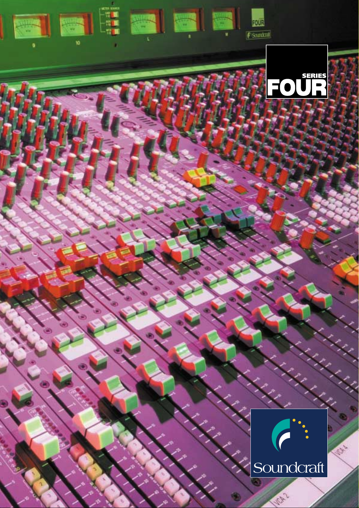
Big spec. Small footprint.
appreciated. Partnered with the SM20
monitor console, the Series FOUR also
provides a flexible audio mixing
solution for live sound venues.
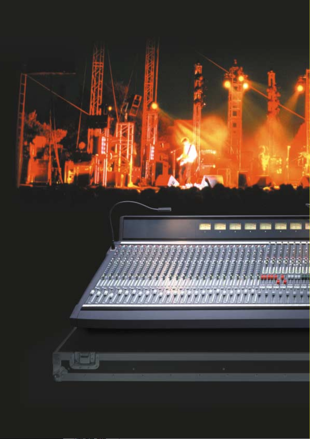
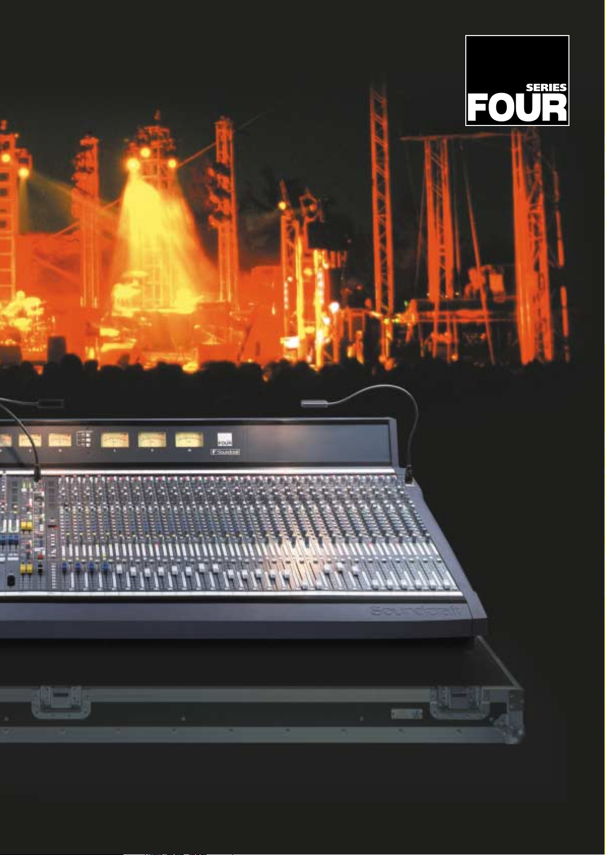
The Series FOUR is available in four
frame sizes providing 24, 32, 40 and 48
mono inputs into 8 group busses, 10
auxiliary busses and stereo and mono
main mix busses. 4 full-function stereo
input channels are also included in
each frame in addition to the mono
modules. The output section includes 8
VCA groups, and a 16x8 matrix section,
which includes feeds from four of the
Aux busses.
Series FOUR is a compact live sound
mixer for front-of-house
applications. Its high feature count
combined with small footprint makes
it ideal for budget-conscious touring
applications, where the familiar
control layout found on its big
brother, the Series FIVE, will be highly
Page 3
• 10 auxiliary busses
• 8 VCA groups
• Built-in 16x8 matrix section
• 4-band fully parametric EQ on both
mono and stereo inputs
• Sweepable filters on all input
channels
•
8 mute groups plus 126 mute snapshots
• Advanced logic-controlled
solo system
• LED input metering on
every channel
• VU output meterbridge
• 100mm channel and master faders
• MIDI programme change
transmission and reception
• 24-48 channel frame sizes
• 4 stereo mic / line inputs with full
EQ as standard
• Rugged power supply with three
year warranty
• Fully modular design in a compact
frame
• 8 subgroups
No endorsement implied. Live photograph copyright of Diana Scrimgeour.
Page 4
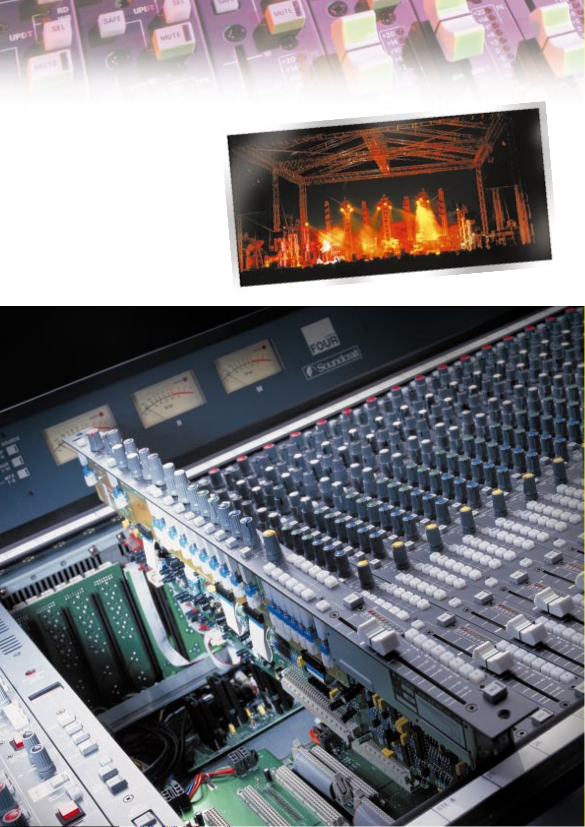
Power and Reliability
Professionals need a console that
works the way they do.
The robust, modular construction of
the Series FOUR allows channel strips
to be removed and replaced quickly
and easily. A motherboard bussing
system is used, giving optimum noise
performance and virtually no cables
to disconnect.
Page 5
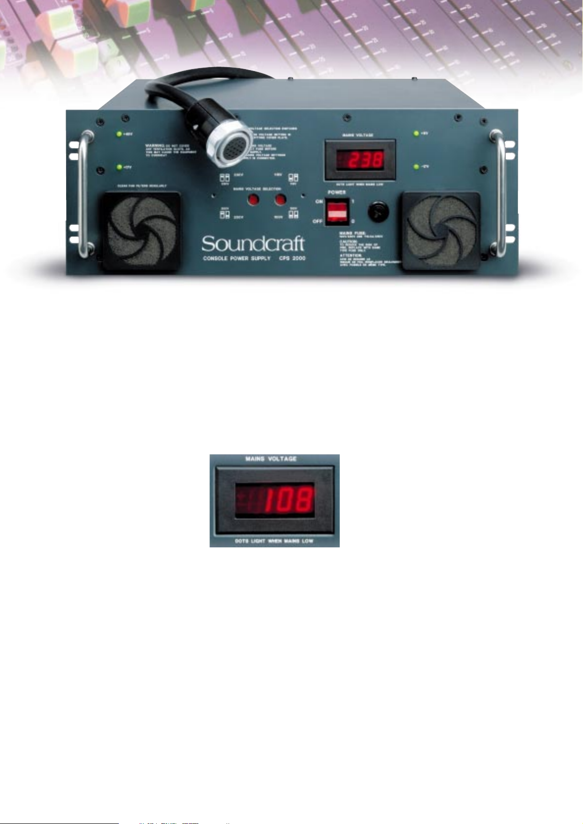
With the Series FOUR in use all around
the world, its power supply needs to be
capable of operating reliably at many
different voltages. The CPS2000 features
a front panel digital display, providing
precise monitoring of incoming voltage,
with a warning indicator when the mains
voltage falls to within 3% of the
dropout point.
• Linear circuitry, using industry standard
components
• Fewer voltage rails for greater
simplicity and reliability
• Load is spread across several power
devices on each rail, for optimum heat
dissipation
• Heavy current wiring is all hard
soldered, minimising number of
connectors
• Built-in diode output linking allows
two supplies to be paralleled for
redundant operation, without a
separate switcher box
• Heavy-duty Socapex® DC connectors
on both the console and power supply
• Thermal sensing fan speed control for
reduced noise and longer life
• Housed in a 4U 19" rack-mountable
case
• Three year warranty
T
he Series FOUR console is shipped
with the ultra high-powered
CPS2000, as used on the Series
FIVE and FIVE Monitor consoles. This
power supply unit features high quality
components and uses fewer voltage
rails for a simpler, more reliable system.
Safety and performance are
demonstrated throughout the CPS2000.
It features built-in diode linking,
enabling two units to be used in parallel
for fail-safe operation without the need
of an external switching box. Heavy-duty
Socapex® DC connectors link the PSU to
the Series FOUR console, with heavy
current wiring used throughout the PSU
for optimum performance.
The CPS2000 features quiet PAPST®
thermostatically controlled fans, forcing
filtered air through the unit. All voltage
rails are protected against short circuits
and excess temperature, with front panel
status LEDs indicating thermal shutdown
and low mains power.
Page 6

Mono Input Module
WIDE-RANGE, LOW-NOISE INPUT PRE-AMP
The input stage uses the same circuit as used
on our Series FIVE console, and was developed
in response to feedback our customers gave us.
The XLR input can handle mic or line level signals
up to +30dBu, with the ‘Range’ switch selecting
high or low sensitivity. This uses patented active
circuitry rather than a PAD, which would degrade
the noise performance and the common mode
rejection of the stage. The 48V switch applies
phantom power, and the Phase switch reverses
the phase of the signal.
SWEEPABLE HIGH-PASS FILTER
Good filters are incredibly useful and the FOUR
gives you the capability to clean up the low end of
an input signal, minimising the amount of
corrective EQ, which needs to be applied. The filter
covers the range 20-700Hz, and can be completely
bypassed when not required.
BALANCED INSERT POINT WITH IN/OUT SWITCH
The channel insert point uses separate balanced
jacks for send and return. It is normally positioned
immediately after the filter and before the
equaliser, but can be repositioned using internal
jumpers to be post-EQ if required.
EQ
The EQ section is based on the same circuits used in
Series FIVE. Four sweepable bands are provided, and
the two mid bands are fully parametric, with
adjustable Q. The HF and LF bands can be switched
to work either as shelving or Bell controls. The
frequency ranges are 30-480Hz (LF), 70Hz-1.5kHz
(Low mid), 450Hz-12kHz (High mid) and 1-20kHz
(HF). +/-15dB of cut or boost is available at any
frequency, and the Q on the two mid bands is
variable from 0.5-3.0. The EQ can be switched out
of the circuit when not required.
ROUTING AND PAN CONTROLS
The post-fade signal is routed to the 8 mono
subgroup and main stereo mix bus and mono mix
bus using individual routing switches. The pan
control always controls the stereo mix bus feed, but
can also be switched by the PAN switch to control
the subgroups. The Mono or Centre bus is ideal for
creating a separate feed for a centre cluster or
sub-bass system. The LCR switch allows true LCR
panning between the Left, Mono/centre and Right
buses. In LCR mode, when the pan pot is in the
centre, no signal appears on left and right outputs.
AUXILIARY SENDS
10 Aux sends are provided, all of which are
switchable pre or post-fader in pairs. When pre-fade,
internal links allow the source to be changed from
post-EQ to pre-EQ, with or without muting with the
channel mute. Aux 1-2 and 3-4 have dual concentric
controls, and either or both pairs can be globally
switched to work as a stereo send, with the lower
control becoming the pan pot. The layout of the
output section means that, on those occasions when
6 aux sends is enough, these two stereo sends can be
used as additional stereo subgroups - they even have
access to the matrix outputs.
DIRECT OUTPUT
A balanced direct output is available on a male XLR
on the rear panel. This is normally fed from the
output of the channel fader, but pressing the DIR
switch on Aux 10 allows it to be controlled from
the Aux 10 pot, and its associated pre-fade internal
link options.
FADER AND MUTING
A high-quality 100mm channel fader controls the
level to all busses, and has 10dB of gain when full
up, as well as an expanded scale around the critical
unity gain area, for maximum resolution.
The Channel mute switch defeats all post-mute
feeds from the input channel, and can be remotely
controlled by the console’s mute master section,
allowing creation of up to 8 mute groups.
A semi-recessed Mute Safe switch allows the
channel to be prevented from remote muting by
Mute groups, but still allows it to be locally muted.
MUTE GROUP AND VCA GROUP ASSIGNMENT
Each input channel can be assigned to any
combination of 8 mute groups and/or 8 VCA
groups, using the dual-function recessed switch
bank next to the fader. The Assign Mode (Mute
or VCA) has to be selected first using a global
switch on the Master module. When pressed, the
switches next to the fader will illuminate in green
when VCAs are assigned, or red when Mute groups
are assigned. The corresponding mute master
buttons and VCA master faders are located on
the master module.
LED INPUT METERING
Every channel is fitted with a 10-segment
peak-reading bargraph meter, positioned next
to each fader for maximum visibility and giving
immediate and graphic indication of incoming
signals. An internal jumper changes the source
from pre-EQ to post-fade. The top LED in the
meter is configured as a Peak LED, and monitors
the signal path in three places, (pre-EQ, post-EQ
and post-fader) giving warning that the signal is
within 3dB of clipping.
SOLO SWITCH
The Solo button provides a mono PFL or stereo AFL
feed to the engineer’s headphones and monitor
outputs, or triggers a destructive solo-in-place,
depending on mode selection at the master section.
Intercancel or additive soloing is possible, with or
without input priority, and solos can be cleared
with a single button press at the master section.
Page 7

Stereo Input Module
F
our stereo input modules are fitted to
all Series FOUR consoles. These are
designed to serve either as FX returns,
or full-function input channels for any stereo
sources including microphones.
The stereo module is as close as possible to two
mono inputs in a single strip. Additional stereo
inputs can be added in blocks of four, in place of
mono inputs, to radically expand the number of
possible inputs to the console - e.g. a 40ch frame
with 16 stereo modules fitted gives a massive 60
microphone-capable inputs in an extremely
compact size.
INPUT STAGE
The same wide-range mic/line input stage as on
the mono input is used, with a dual concentric
control adjusting left and right gain independently.
Independent RANGE and 48V switches are provided
for left and right channels, and the left channel
can be phase inverted using the Phase switch, to
correct wiring problems or for special effects. (An
internal link option allows the switch to reverse
both left and right inputs.)
SWEEPABLE HIGH-PASS FILTER
Ganged high pass filters are provided for left and
right channels; they are switched out of the signal
path by a click switch at the end stop of the
frequency control.
EQ
The equaliser is a full stereo implementation of the
mono channel EQ. The EQ can be switched in or out
of the signal path.
INSERT POINTS
Separate left and right insert points are provided.
The send and returns are fully balanced on separate
jacks, and the insert point can be switched in or
out of the circuit.
AUX SENDS
Full access to all 10 Aux sends is provided, as with
the mono input. Each pair of sends is switchable
pre/post fader. Internal switches allow each pair
of sends to be either sourced individually from a
mono sum of L and R signals or to be fed as stereo
pairs of sends from L and R module signals.
ROUTING AND PAN CONTROLS
The post-fade stereo signal is routed to the 8
subgroup and main stereo and mono mix busses
using the individual routing switches. Two pan pots
are provided, using a dual concentric control - one
each for the left and right channels. This means
that exact control of the stereo image width is
possible by setting the two pan pots at various
positions away from centre, and also allows
independent panning of the two inputs connected
to the module. The Mono or Centre bus is
independent of the pan control, and is derived
from a sum of the left and right signals.
FADER AND MUTING
A high-quality 100mm stereo channel fader
controls the level to all busses, and has the same
scaling as the mono inputs. The Channel mute
switch mutes both left and right channels and
all post-mute Aux sends, and can be remotely
controlled by the console’s mute master section,
in the same way as for the mono input. A recessed
Mute Safe switch is also fitted - this is useful when
the stereo channel is used as an FX return, and
effectively prevents the channel from being muted
by either the master muting system or the
solo-in-place system.
MUTE GROUP AND VCA ASSIGNMENT
As with the mono inputs, each stereo input can be
assigned to any combination of the 8 Mute Groups
and 8 VCA subgroups, using the dual function
assign switch bank beside the fader. Both left and
right channels of the module will be controlled
as a pair from any one or more of the 8 VCA
master faders.
LED INPUT METERING
Two peak-reading 5-segment input meters are
positioned adjacent to the fader, and meter the left
and right input signals immediately after the input
gain stages. The top LED in each bar is configured
as a Peak LED, and monitors the signal path in
three places, (pre-EQ, post-EQ and post-fader)
giving warning that the signal is within 3dB
of clipping. The meter point is internally switchable
to be post-fader, if required.
SOLO SWITCH
The Solo button provides mono sum PFL or stereo
AFL feeds to the engineer’s headphones or
monitors, or activates a destructive solo-in-place,
depending on mode selection at the master section.
Intercancel or additive soloing is possible.
Page 8

Output Section
T
he output section of the FOUR is packed
with powerful features. It provides the
master output level controls for the 8
Subgroups, 10 Aux sends, 8 matrix, and stereo
and mono main mix busses, plus master facilities,
aux return, oscillator and talkback.
The layout of the subgroup and Aux masters has
been specially designed to allow excellent
flexibility, depending on the numbers of subgroups
and aux sends required for each job. All the
subgroup and aux master outputs have identical
facilities, so that if 8 subgroups are not enough for
a particular job, some of the aux sends can be used
as additional subgroups. Thus all the aux master
sections have 60mm faders, insert points and
routing to the main mix busses. In addition, Aux
masters 1-4 have access into the matrix outputs.
8 SUBGROUP MASTER FADERS
Each of the 8 subgroups has a 60mm master fader
controlling signal level to the electronically
balanced output XLR on the rear panel. Each group
is equipped with PFL or AFL solo and automated
mute, plus a fully balanced insert point with in/out
switch. The STE and MNO buttons route the
subgroup signal to the main stereo and mono
(centre) busses. The PAN control allows positioning
of the subgroup signal within the stereo field. The
LCR switch changes the pan mode to true LCR, as
on the mono input modules.
10 AUX MASTER FADERS
Each Aux master has identical facilities to the
subgroups described above. This allows any spare
aux sends to be used as subgroups if required.
Aux 1-4 also have global mono/stereo switching,
and can be sent to the 8 matrix outputs, for even
more subgrouping flexibility.
GLOBAL MONO/STEREO SWITCHING
Aux 1/2 and 3/4 have a Global Mode switch on
their output section. This allows these two pairs of
sends to be easily configured as mono or stereo
sends. When set to stereo, the dual concentric
input send pots are automatically configured as
stereo level on top, and pan on bottom. In mono
mode, top and bottom work as independent mono
sends. In addition, in stereo mode, the Solo
buttons on the output section are logic-linked
for convenience.
MATRIX OUTPUTS 1-8
8 matrix outputs allow individual mixes to be
derived from the 8 subgroups, left, right and
Mono(centre) outputs, plus Aux 1-4 and an
individual external line input. All the matrix
outputs appear on electronically balanced XLRs
on the rear of the console. Each matrix output
has a rotary fader, AFL or PFL solo, and automated
Mute button with recessed mute safe switch.
The TB button on each output routes talkback, tone
or pink noise from the central talkback/oscillator
section. All matrix outputs feature fully balanced
insert points with in/out switch.
VCA MASTER FADERS
8 VCA master faders control the levels of any
mono or stereo input channels assigned to them.
An associated Mute button is provided for each
fader – operating this switch acts as a remote
control of the Mute buttons on the assigned
channels.
Subgroups 1-8 / Aux 5-8
Aux 1/2 & 3/4 with global stereo / mono switch
Aux 9/10
Page 9

Master Section
T
he master section contains the main stereo
and mono (centre) output faders, Aux
return, plus monitor and solo controls,
talkback and test oscillator.
MASTER FADERS
Three 100mm faders control the left, right and
mono (centre) output levels. These are fed to
balanced XLRs on the rear panel.
INSERT POINTS
Pre-fade insert points are provided for left,
right and mono (centre) outputs. These are
fully balanced and use separate jacks for send
and return.
ALTERNATE STEREO OUTPUT
In addition to the main stereo mix outputs, an
Alternate stereo output is provided, derived either
pre- or post- the main stereo master faders. This
output is controlled by a pair of 60mm faders and
can be switched to a mono sum if necessary. In this
case you then have two additional fader-controlled
mono outputs. The outputs appear on balanced
XLRs on the rear panel. This pair of outputs is
invaluable for providing a last-minute stereo feed
for broadcast or recording, or supplying a stereo
or mono mix to an additional flown system.
MONITOR SECTION
Separate level controls and outputs are provided
for engineer’s monitor speakers and headphones.
Both these outputs normally receive either the
main stereo bus signal, mono bus signal, Aux return
(2TK) or nothing, depending on the Monitor Source
selection switch settings, but this is automatically
overridden by any input or output solo signal.
A high-power headphone amp drives two
parallel-connected headphone sockets, one
recessed into the fader panel area below Aux 9/10
master faders, the other on the rear panel.
SOLO CONTROLS
The FOUR incorporates an advanced logic-controlled
solo system, giving a number of useful features:
The Solo Clear button allows any solo on the
console to be cancelled at the touch of a button.
The PFL/AFL Master Mode button controls which
type of solo is obtained across the whole console
when any solo button is pressed. Either mono PFL
or stereo AFL can be chosen using this switch.
The PFL and AFL trim controls give +/-10dB of level
adjustment of the soloed signals in the monitor /
phones output.
The Autocancel On button, when selected, allows
any solo button selected to cancel the previous
solo. When this mode is not selected, solos can be
selected additively.
The Input Priority On button, when selected, allows
an input solo to temporarily override any output
solo which may be present. When the input solo is
released, the original output solo will reappear on
the monitors.
The Solo-In-Place Enable button (with 2 second press
and hold, for safety) selects destructive in-place
stereo solo rather than mono PFL or stereo AFL.
Group, Aux and Matrix output solos remain in either
PFL or AFL mode, regardless of this switch setting.
TALKBACK AND OSCILLATOR SECTION
The talkback and oscillator signals can access any
of the console busses, including matrix outputs, by
means of the local TB/OSC buttons on each output
section. The talkback section has front and rear
panel XLRs for mic or line level signals, with
phantom power capability. The mic signal can be
routed either to selected internal busses, by
pressing the Talk to Outputs button, or sent to a
ClearCom™-compatible intercom system using the
EXT button. The CALL button is used to send a Call
signal onto the loop. An incoming CALL signal
from a remote station will cause the console
Littlites™ to flash, alerting the engineer.
Page 10

Master Section
A Soundcraft proprietary intercom output
(compatible with SM monitor consoles or another
FOUR) is also available. Return talkback from the
ClearCom system is switched onto the headphones,
by pressing the EXT button in response to a CALL
signal, where it dims the programme signal. This
process is automatic when using the Soundcraft
intercom. The oscillator generates either tone
from 63Hz -10kHz or pink noise, and has its
own independent balanced XLR output on the
rear panel.
AUX RETURN
An additional stereo return is fitted to the master
module, with bypassable 2-band shelving EQ at
60Hz and 12KHz, and is routed to either the stereo
or mono mix busses, or both. This return is ideally
suited to cassette or CD music replay. The Mute
button is controlled by the Mute Scene system and
has a recessed ‘safe’ switch, to protect it from
muting during solo-in-place conditions.
The Solo button provides mono PFL, stereo AFL or
Solo-In-Place, depending on the mode selected at
the master section. A rotary fader controls the level
of the return, and the return can be selected for
monitoring on phones even if it is muted.
LEFT AND RIGHT LED METERS
A pair of 16-segment LED peak meters are fitted at
the top of the master module. These provide
accurate metering of main mix outputs and soloed
signals, even if the VU meterbridge is not fitted.
INPUT ASSIGN MODE BUTTONS
Located on the Mute Master module, these two
adjacent buttons are used in conjunction with the
bi-colour illuminated assign switches next to the
input faders, to display and set up VCA and Mute
group assignments.
The two buttons form a toggle switch, so that one
is always active:
Pressing the VCA button puts all the input
VCA/Mute assign switches into VCA assign mode.
The input assign switches illuminate in green when
pressed, to show these assignments.
Pressing the MUTE button puts all the input
VCA/Mute assign switches into Mute group assign
mode. The input assign switches illuminate in red
when pressed to show the mute group assignments.
ASSIGN SAFE SWITCH
If the SAFE switch is pressed, the input assignment
switches cannot be used to make or change
assignments, but they can still be viewed. Toggling
between VCA and Mute Group assign modes by
pressing the VCA or MUTE Master Assign switches
will display the current assignments in green or red
respectively, on the input channels.
MUTE MASTER BUTTONS
These large illuminated buttons allow activation of
the 8 mute groups. Mute groups can be activated
in any combination, and operate separately from
the internal snapshot automation.
MUTE CONTROL/MIDI SECTION
The FOUR incorporates a mute snapshot system
built into the console as standard. This allows the
creation of up to 126 snapshots of the console’s
mute and VCA Assignment status, as well as the
generation and reception of MIDI program change
messages, allowing the console to remotely control
patch changes on an FX rack. Additionally, pressing
any mute button on the console will send out a
MIDI note command, which can be used to trigger
sound effect generation from samplers.
7-SEGMENT DISPLAY AND UP/DOWN BUTTONS
These allow the selection and display of the current
snapshot number. The display flashes if the selected
number does not match the currently active
snapshot.
STORE BUTTON
Pressing this button stores the current mute
settings to the snapshot number shown in the
display. A confirm yes/no message is given.
RECALL BUTTON
Pressing this button recalls the mute snapshot
selected in the display.
PROCESSOR RESET BUTTON
A recessed switch allows the mute control
processor to be disabled in the unlikely event of a
failure. Once disabled, all console mutes and faders
are manually controllable. VCA and Mute group
operation is not possible with the processor
stopped, but the audio path will not be interrupted.
CONSOLE LINKING
All audio busses on the Series FOUR have balanced
line level bus inputs, allowing the outputs of any
other console to be easily connected. If full logic
linking of VCAs and the solo controls to another
Series FOUR is required, an RS232 port allows two
consoles to be linked.
Mute Master Module
Page 11

A removable VU meterbridge contains 10 VU meters for
metering of the Subgroup, Aux and Matrix outputs
(switchable as three banks using the meter source selector
on the overbridge) and 3 larger VU meters dedicated to
the main Left, Right and Mono (centre) outputs. The left
Metering
and right meters automatically switch to read any AFL or
PFL selection. All VU meters are illuminated using LED
backlighting rather than unreliable filament lamps, and
each meter incorporates a large peak LED that illuminates
when the output is within 3dB of clipping.
Architect’s Specifications
The Mixing Console shall be constructed in a chassis that
is itself supported by a rigid steel subframe, and shall be
available in 24, 32, 40 and 48 mono input sizes. All
internal PCBs shall be individual for each channel. The
mixing console shall provide ten auxiliary sends, eight
mono subgroups, as well as stereo and mono outputs.
There shall be an alternative stereo output in addition to
the main. A Mute Scene set system shall be included,
enabling up to 126 scenes to be stored and recalled, with
eight mute groups. The console shall be provided with
4 Stereo Input channels, 1 FX Return, Master Section and
MIDI Scene Set Section. There shall be a fully flexible
matrix system. The console will be supplied with a
separate CPS2000 19-inch rack-mounting Power Supply.
The Mono Input shall have the following features;
electronically balanced low-impedance input via an XLR
socket with a switched continuously variable gain giving
a sensitivity range of -2dBu to -70dBu (high gain range)
and -20dBu to +10dBu for high level inputs, individually
switchable 48V phantom power and a 20 - 700Hz
High-pass filter. A by-passable 4-band equaliser shall be
provided, with switchable bell/shelving response HF and
LF controls with cut-off points 1kHz - 20kHz and
30Hz - 480Hz, and two parametric mid-frequency
controls covering the range of 450Hz - 12kHz and
70Hz - 1.5kHz. The mid bands shall have a Q factor which
is variable between 0.5 and 3.0. All bands shall have a cut
and boost of 15dB (centre detented). 10 auxiliary sends
shall be provided: pairs 1-2 and 3-4 shall have dual
concentric pots, and can be switched to stereo pairs via
global switches on the output modules, and 5-10 shall
have individual level controls. The sends shall be
switchable pre/post fader in pairs. The balanced XLR direct
output shall be switch-selectable from post-fade or from
the Aux 10 pot. Routing to the 8 subgroups shall be
switchable post-fade or post-pan, with an individual
routing switch to each group. The pan control also feeds
the stereo mix bus via the mix switch. Routing to the
mono (centre) mix shall be via a separate switch. There
shall also be an LCR switch which changes the mode of
the pan pot from normal to true LCR panning. Solo and
Mute switches shall control the main signal path and
allow the pre and post fade signals to be monitored at all
times. A mute safe switch shall allow the channel to be
protected against remote muting from Mute Groups, VCA
masters, Solo-in-Place or snapshots. A 10-segment LED
meter (jumperable pre-or post-fade) with separate
multipoint peak indicator shall be provided. Assignment
switches to 8 VCA groups shall be provided in a recessed
area adjacent to the 100mm channel fader. The same
assignment switches shall be used to assign up to 8 mute
groups, using a global VCA/Mute Group mode switch, and
bi-colour indication in the assign switches. There shall be
a pre-EQ insert point (insert can be internally switched
pre or post EQ - default=pre) using separate balanced
jacks for send and return, enabled by an ‘insert in’ switch.
The Stereo Input shall have the following features;
stereo mic or line level input on balanced XLRs with a
continuously variable gain range giving a sensitivity of
-2dBu to -70dBu (high gain range) and -20dBu to
+10dBu for high level inputs, individually switchable 48V
phantom power for left and right inputs, a 20 - 700Hz
ganged High-pass filter and phase switch which operates
either on left channel only or both left and right
(internally jumperable). A by-passable 4-band equaliser
shall be provided, with exactly the same facilities as the
mono input. 10 auxiliary sends shall be provided: pairs
1-2 and 3-4 shall have dual concentric pots, and 5-10
shall have individual level controls. These sends shall be
switchable pre/post fader in pairs. Each pair of sends shall
be switched to be fed by a mono sum of the module or
alternately left/right, using internal switches. Routing
to the 8 subgroups shall be switchable post-fade or
post-pan, with an individual routing switch to each
group. Independent pan controls are provided for the left
and right halves of the module, they also feed the stereo
mix bus via the mix switch. Routing to the mono (centre)
mix shall be via a separate switch. Solo and Mute
switches shall control the main signal path and allow the
pre or post fade signal to be monitored at all times, with
Mute Safe for protection from remote muting. Twin
5-segment LED meters (jumperable pre- or post-fade) for
left and right channels with separate multipoint peak
indicator shall be provided. Assignment switches to 8 VCA
groups shall be provided in a recessed area adjacent to
the 100mm stereo channel fader. The same assignment
switches shall be used to assign up to 8 mute groups,
using a global VCA/Mute Group mode switch, and
bi-colour indication in the assign switches. There shall be
pre-EQ insert points (insert can be internally switched pre
or post EQ - default=pre) for left and right channels, each
using separate balanced jacks for send and return,
enabled by a single ‘insert in’ switch.
Eight Group Outputs, 10 Aux Outputs, 8 Matrix Outputs
shall be provided, using 8 combined Matrix/Aux/Group
master channels, plus an additional Aux-only module for
Auxes 9,10. The Group/Aux master sections shall each
have a 100mm fader, an illuminated Mute switch and an
illuminated Solo switch. The Group/Aux outputs shall be
routable to the main mono (centre) bus via a switch, and
to the main stereo busses via a pan pot and a switch.
Panning shall be switchable either normal LR or true LCR.
They shall each have an insert point via separate balanced
jacks for send and return, with an ‘insert in’ switch. 8
Matrix outputs shall be provided, located above the
Group/Aux sections. Each Matrix O/P shall receive a
contribution from each of the 8 groups, Mix L, R and mono
(centre), Aux 1-4, and an External line input. The Matrix
output shall be controlled by a master rotary fader with
associated illuminated Mute and Solo controls. The Output
shall be electronically balanced, and an insert point shall
be provided on separated balanced jacks for send and
return, enabled by an ‘insert in’ switch. The Grp/Aux
master modules controlling Aux 1,2 and 3,4 shall each
have a global switch for selecting mono or stereo
operation for these pairs of sends. Balanced line inputs
shall be provided for all console busses, in order to link a
second console. The Master Module shall have 3 x 100mm
master faders which control L, R and mono (centre)
outputs, Solo Clear, master AFL/PFL selection, Solo-in-Place
and Auto Cancel selection, Talkback microphone socket
and switching, oscillator and monitor controls. An
Alternate Stereo Output shall be provided, derived from
the main stereo output and switchable pre or post the
main faders; this shall be switchable to a mono sum. A
Stereo Aux Return shall be provided for stereo line level
inputs, with rotary volume, 2-band shelving EQ at 60Hz
and 12KHz, and snapshot controlled mute. The console will
have an overbridge as standard, with 3 large VU meters to
monitor Left Mix, Right Mix and mono (centre) Mix; it will
also have 10 smaller VU meters to monitor Group/ Aux/
Matrix Outputs, as selected by a 3-position meter source
switch bank. The left and right meters shall automatically
switch to read an AFL or PFL solo, whenever one is
activated. The console shall be provided with 8 VCA master
faders with associated Mute switches, for control of the
input channels. The Mute shall activate the Mute buttons
of any assigned channels. The MIDI Scene Set section shall
be capable of storing up to 126 snapshots comprising
mono and stereo input mutes and group, aux, matrix
output mutes and input VCA Assignments (if enabled). A
MIDI Program change message shall be transmitted upon
recalling a snapshot. A 3-digit LED display shall be used to
show snapshot number for the current snapshot. Eight
mute master buttons shall be used to activate mute
groups; these shall work independently of the snapshot
system. Presetting of external devices shall be possible via
MIDI Program Changes and Note On/Off data.
The dimensions and specifications shall be as published on
the rear cover of this brochure. The console shall be the
Soundcraft Series FOUR.
Page 12
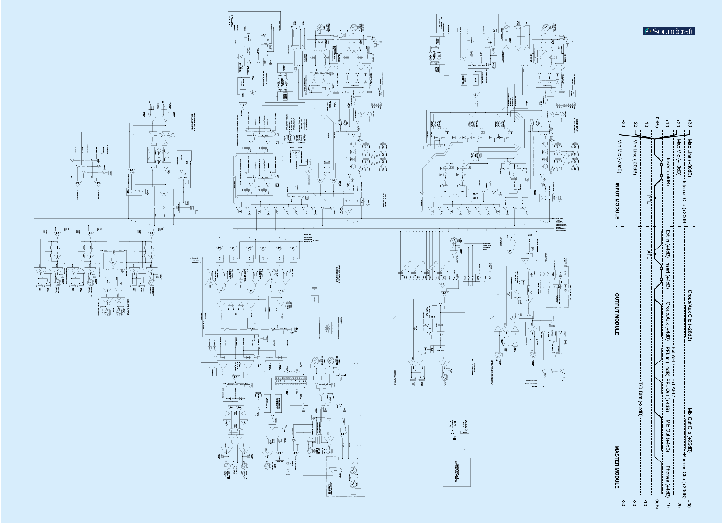
System Block
Diagram
Level
Diagram
Page 13

Dimensions & Configs
SUBFRAME
38.80
(1.52")
70.80 (2.78")
BOTH ENDS
I/P
17-24
STEREO
I/P 1-4
OUTPUT + MASTER
SECTION
I/P 1-16
All dimensions are mm (inches)
24+4 channel console shown below.
Larger sizes have 8 extra mono inputs on the left hand side.
The 40+4 has an additional 8 inputs on the right hand side
and the 48+4 has an additional 16 inputs.
Console Overall Width
24+4 frame
32+4 frame
40+4 frame
48+4 frame
1366mm (53.80")
1620mm (63.78")
1874mm (73.78")
2128mm (83.78")
Page 14

EQ Curves
Input / Output Specifications
Outputs Insert points Inputs
Output
Master
Tip - Signal Hot
Ring - Signal Cold
Sleeve - Ground
Module Signal Connector Pin Nom. Level Max. Level Impedance
Mono Input Female Pin 1 - Ground -70 to -2dBu +30dBu 2kΩ
Input XLR Pin 2 - Signal Hot -20 to +10dBu
Pin 3 - Signal Cold (Switched Range)
Stereo STE IN Female Pin 1 - Ground -70 to -2dBu +30dBu 2k2Ω
Input (Left & XLR Pin 2 - Signal Hot -20 to +10dBu
Right) Pin 3 - Signal Cold (Switched Range)
Matrix Ext. In Female Pin 1 - Ground +4dBu +26dBu > 10kΩ
XLR Pin 2 - Signal Hot
Pin 3 - Signal Cold
TB Mic Female Pin 1 - Ground -20 to -70dBu 0dBu 2kΩ
I/P XLR Pin 2 - Signal Hot
Pin 3 - Signal Cold
EXT TB Female Pin 1 - Ground +4dBu +26dBu > 10kΩ
Master I/P XLR Pin 2 - Signal Hot
Pin 3 - Signal Cold
Aux Returns Female Pin 1 - Ground +4dBu +26dBu > 10kΩ
(L & R) XLR Pin 2 - Signal Hot
Pin 3 - Signal Cold
Mono Channel TRS Send +4dBu +26dBu (into 4kΩ) Send < 75Ω
Input Snd & Ret (
1
/4" Jack) Return +4dBu +21dBu Return > 15kΩ
Stereo Channel TRS Send +4dBu +26dBu (into 4kΩ) Send < 75Ω
Input (L & R) Snd & Ret (
1
/4" Jack) Return +4dBu +21dBu Return > 15kΩ
Matrix Matrix TRS Send +4dBu +26dBu (into 4kΩ) Send < 75Ω
Snd & Ret (
1
/4" Jack) Return +4dBu +21dBu Return > 15kΩ
Group/Aux Group/Aux TRS Send +4dBu +26dBu (into 4kΩ) Send < 75Ω
Master Snd & Ret (
1
/4" Jack) Return +4dBu +21dBu Return > 15kΩ
Output Main Mono, TRS Send +4dBu +26dBu (into 4kΩ) Send < 75Ω
Master L&R, Snd & Ret (
1
/4" Jack) Return +4dBu +21dBu Return > 15kΩ
Mono Direct Male Pin 1 - Ground +4dBu +26dBu (into 2kΩ) < 75Ω
Input Output XLR Pin 2 - Signal Hot
Pin 3 - Signal Cold
Matrix Matrix Male Pin 1 - Ground +4dBu +26dBu (into 2kΩ) < 75Ω
Output XLR Pin 2 - Signal Hot
Pin 3 - Signal Cold
Group Group Male Pin 1 - Ground +4dBu +26dBu (into 2kΩ) < 75Ω
Master Output XLR Pin 2 - Signal Hot
Pin 3 - Signal Cold
Aux Aux Male Pin 1 - Ground +4dBu +26dBu (into 2kΩ) < 75Ω
Master Output XLR Pin 2 - Signal Hot
Pin 3 - Signal Cold
L/R/Mono/Alt Male Pin 1 - Ground +4dBu +26dBu (into 2kΩ) < 75Ω
L&R Outputs XLR Pin 2 - Signal Hot
Pin 3 - Signal Cold
Ext TB Male Pin 1 - Ground +4dBu +26dBu (into 2kΩ) < 75Ω
Output XLR Pin 2 - Signal Hot
Pin 3 - Signal Cold
Oscillator Male Pin 1 - Ground +4dBu +14dBu (into 2kΩ) < 75Ω
Output XLR Pin 2 - Signal Hot
Pin 3 - Signal Cold
Headphones TRS Tip - Left +4dBu +20dBu (into 600Ω) 50Ω
Output (
1
/4" Jack) Ring - Right 1W (into 8Ω)
Sleeve - Ground
Console All Female Pin 1 - Ground +4dBu +26dBu > 15kΩ
Linking Inputs XLR Pin 2 - Signal Hot
Inputs Pin 3 - Signal Cold
Page 15

Series FOUR Typical Specifications
SOUNDCRAFT
HARMAN INTERNATIONAL INDUSTRIES LTD.
CRANBORNE HOUSE, CRANBORNE RD.,
POTTERS BAR, HERTS,EN6 3JN, UK.
TEL: +44 (0)1707 665000
FAX:+44 (0)1707 660742
EMAIL: info@soundcraft.com
http://www.soundcraft.com
SOUNDCRAFT USA
1449 DONELSON PIKE,
NASHVILLE TN 37217, USA.
TEL: 1-615-360-0471
FAX: 1-615-360-0273
EMAIL: soundcraft-usa@harman.com
http://www.soundcraft.com
Soundcraft reserve the right to improve or otherwise alter any information
supplied in this document or any other documentation supplied hereafter.
E&OE 08/01
This equipment complies with the EMC Directive 89/336/EEC
Note: These figures are typical of performance in a
normal electromagnetic environment. Performance
may be degraded in severe conditions
Part No. A4; ZL0541
US; ZL0542
Frequency Response XLR Input to any Output . . . . . . . . . . . . . . . . . +0/-0.5dB, 20Hz - 20kHz
T. H. D. XLR In to Group or Mix Out . . . . . . . . . . . . . . Less than 0.015% @ 1kHz
(All measurements Less than 0.04% @ 10kHz
at +4dBu)
Noise Mic Input E. I. N. . . . . . . . . . . . . . . . Less than -127.5dBu (200Ω source)
(22Hz - 22kHz, Group Output Noise . . . . . . . . . . . . . . . Less than -80dBu (40ch routed)
unweighted) Mix Output Noise . . . . . . . . . . . . . . . . . Less than -80dBu (40ch routed)
Crosstalk Input Channel Muting . . . . . . . . . . . . . . . . . . . . . . . . Greater than 100dB
(All measurements Input Channel Send Pot Isolation . . . . . . . . . . . . . . Greater than 100dB
at 1kHz) Group Fader Isolation . . . . . . . . . . . . . . . . . . . . . . . . . Greater than 95dB
Group to Group Crosstalk . . . . . . . . . . . . . . . . . . . . . . . . Less than -90dB
Group to LR Crosstalk . . . . . . . . . . . . . . . . . . . . . . . . . . . Less than -90dB
Input and Output Input . . . . . . . . . . . . . . . . . . . . . . . . . . . . . . . . . . . . . . . . . . . 2kΩ balanced
Impedances All Insert Sends . . . . . . . . . . . . . . . . . . . . . . . . . . Less than 75Ω balanced
All Insert Returns . . . . . . . . . . . . . . . . . . . . Greater than 15kΩ balanced
Outputs . . . . . . . . . . . . . . . . . . . . . . . . . . . . . . . . Less than 75Ω balanced
Input/Output Maximum Input Level . . . . . . . . . . . . . . . . . . . . . . . . . . . . . . . . . . +30dBu
Capability All Input Insert Sends . . . . . . . . . . . . . . . . . . . . . . . . . . +26dBu into 4kΩ
All Output Insert Sends . . . . . . . . . . . . . . . . . . . . . . . . . +26dBu into 4kΩ
All Insert Returns . . . . . . . . . . . . . . . . . . . . . . . . . . . . . . . . . . . . . . +26dBu
All Balanced Outputs . . . . . . . . . . . . . . . . . . . . . . . . . . +26dBu into 4kΩ
Headphone Output . . . . . . . . . . . . . . . . +20dBu into 600Ω, 1W into 8Ω
Input and Output Input Sensitivity (XLR) . . . . . . . . . -2dBu to -70dBu, +10dBu to -20dBu
Levels Insert Sends/Returns . . . . . . . . . . . . . . . . . . . . . . . . . . . . . +4dBu nominal
Outputs . . . . . . . . . . . . . . . . . . . . . . . . . . . . . . . . . . . . . . . . +4dBu for 0VU
Oscillator 63Hz to 10kHz / pink noise, variable level
Filters 20-700Hz high-pass
EQ HF . . . . . . . . . . . . . . . . . . . . . . . . . . . . . . 1 - 20kHz, +/-15dB, bell or shelf
Hi-Mid . . . . . . . . . . . . . . . . . . . . . . . 450 - 12kHz, +/-15dB, Q = 0.5 - 3.0
Lo-Mid . . . . . . . . . . . . . . . . . . . . . . . 70 - 1.5kHz, +/-15dB, Q = 0.5 - 3.0
LF . . . . . . . . . . . . . . . . . . . . . . . . . . . . . 30 - 480Hz, +/-15dB, bell or shelf
Metering VU Meterbridge with 10 VU meters selectable between
Groups 1-8, Aux 1-10 or Matrix 1-8 and 3 VU meters for the
main mix outputs.
Each meter has a peak LED set to 3dB below clipping level.
Input Module . . . . . . . . . . . . . . . . . . . . . 10-LED bargraph incl. peak LED
Weight 24ch - 68 kg (150 lbs), 32ch - 91 kg (200 lbs),
40ch - 106 kg (233 lbs), 48ch - 121 kg (266 lbs), incl. meterbridge
Operating Conditions -10°C to +30°C, 0% to 80% humidity
 Loading...