

Page 1

FIVE Monitor Contents 1
Page 2

2 FIVE Monitor Contents
© Harman International Industries Ltd. 1997
All rights reserved
Parts of the design of this product may be protected by worldwide patents.
Part No. ZM0228
Issue 1
Soundcraft is a trading division of Harman International Industries Ltd.
Information in this manual is subject to change without notice and does not represent a commitment on the part of the vendor. Soundcraft shall not be liable for
loss or damage whatsoever arising from the use of information or any error contained in this manual.
No part of this manual may be reproduced, stored in a retrieval system, or transmitted, in any form or by any means, electronic, electrical, mechanical, optical,
chemical, including photocopying and recording, for any purpose without the
express written permission of Soundcraft.
It is recommended that all maintenance and service on the product should be carried out by Soundcraft or its authorised agents. Soundcraft cannot accept any liability whatsoever for any loss or damage caused by service, maintenance or repair
by unauthorised personnel.
Harman International Industries Limited.
Cranborne House,
Cranborne Road,
Cranborne Industrial Estate,
Potters Bar,
Herts.,
EN6 3JN
UK.
Tel: 01707 665000
Fax: 01707 660482
Page 3

FIVE Monitor Contents i
FIVE MMonitor
Contents
1. Introduction 1.1
Introduction 1.2
Warranty 1.2
2. Installation 2.1
Dimensions 2.2
Precautions and Safety Instructions 2.3
Mains Installation 2.4
Connections 2.6
Block Diagrams 3.1
24-bus Mono Input Module 3.2
32-bus Mono Input Module 3.3
24-bus Stereo Input Module 3.4
32-bus Stereo Input Module 3.5
32-bus Output Module 3.6
Master Module 3.7
EQ Output Module 3.10
Functional Description 4.1
Mono Input Module 4.2
Stereo Input Module 4.6
Output Module 4.10
Master Module 4.14
Specifications 5.1
Page 4

ii FIVE Monitor Contents
Page 5

FIVE Monitor Introduction 1.1
FFIIVVEE MMoonniittoorr
IInnttrroodduuccttiioonn
1
Page 6

1.2 FIVE Monitor Introduction
IInnttrroodduuccttiioonn
Congratulations on purchasing a Soundcraft console.
Series FIVE Monitor is a dedicated Monitor mixing console designed to meet the
exacting requirements of major tours and installations.
SSyysstteemm OOvveerrvviieeww
l Available in two versions: 24+2 or 32+2 bus
l Frame sizes from 40-60 mono inputs
l Optional stereo input module
l 4-band parametric EQ on all inputs including stereos
l Sends can be globally configured as mono or stereo
l Comprehensive output matrix built-in
l 8 VCA Groups plus 8 Mute groups
l Remote control of BSS Varicurve via midi
l LED input metering plus VU output metering
PPoowweerr SSuuppppllyy
l The FIVE Monitor uses the CPS2000 Power Supply.
Page 7

FIVE Monitor Introduction 1.3
WWaarrrraannttyy
1 Soundcraft is a trading division of Harman International Industries Ltd .
End User means the person who first puts the equipment into regular
operation.
Dealer means the person other than Soundcraft (if any) from whom the
End User purchased the Equipment, provided such a person is authorised
for this purpose by Soundcraft or its accredited Distributor.
Equipment means the equipment supplied with this manual.
2 If within the period of twelve months from the date of delivery of the
Equipment to the End User it shall prove defective by reason only of faulty
materials and/or workmanship to such an extent that the effectiveness
and/or usability thereof is materially affected the Equipment or the defec-
tive component should be returned to the Dealer or to Soundcraft and
subject to the following conditions the Dealer or Soundcraft will repair or
replace the defective components. Any components replaced will become
the property of Soundcraft.
3 Any Equipment or component returned will be at the risk of the End User
whilst in transit (both to and from the Dealer or Soundcraft) and postage
must be prepaid.
4 This warranty shall only be available if:
a) the Equipment has been properly installed in accordance with instruc-
tions contained in Soundcrafts manual; and
b) the End User has notified Soundcraft or the Dealer within 14 days of the
defect appearing; and
c) no persons other than authorised representatives of Soundcraft or the
Dealer have effected any replacement of parts maintenance adjustments or
repairs to the Equipment; and
d) the End User has used the Equipment only for such purposes as
Soundcraft recommends, with only such operating supplies as meet
Soundcrafts specifications and otherwise in all respects in accordance
Soundcrafts recommendations.
5 Defects arising as a result of the following are not covered by this
Warranty: faulty or negligent handling, chemical or electro-chemical or
electrical influences, accidental damage, Acts of God, neglect, deficiency in
electrical power, air-conditioning or humidity control.
6 The benefit of this Warranty may not be assigned by the End User.
7 End Users who are consumers should note their rights under this Warranty
are in addition to and do not affect any other rights to which they may be
entitled against the seller of the Equipment.
Page 8

1.4 FIVE Monitor Introduction
Page 9

FIVE Monitor Installation 2.1
FFIIVVEE MMoonniittoorr
IInnssttaallllaattiioonn
2
Page 10
2.2 FIVE Monitor Installation
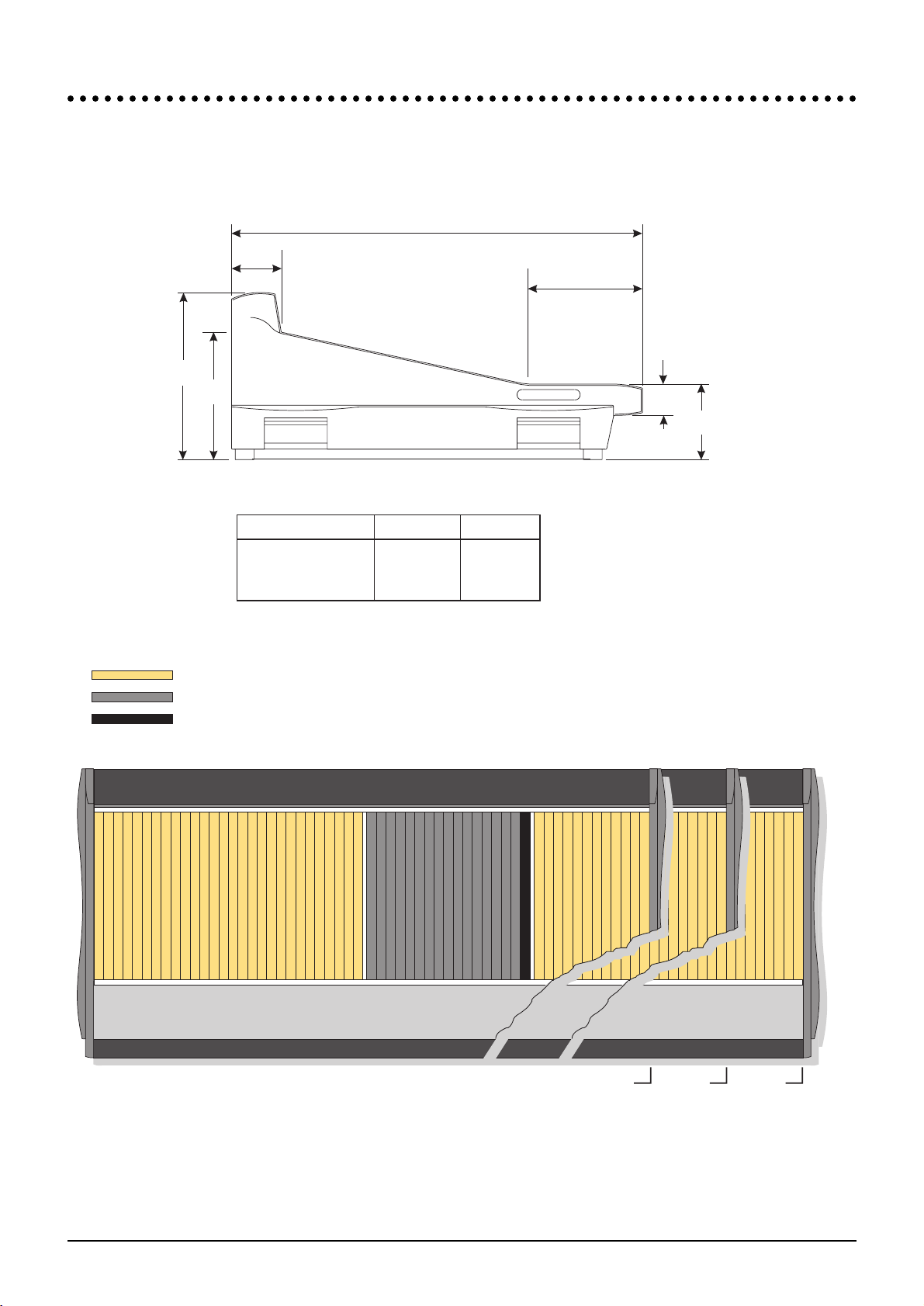
DDiimmeenniioonnss
All dimensions are in millimeters (inches in brackets)
914.00
(35.98")
251.12
(9.89")
112.35
(4.42")
69.64
(2.74")
284.46
(11.20")
373.18
(14.69")
169.38
(6.67")
CONSOLE TOTAL WIDTH WEIGHTS
32-bus,
32-bus,
32-bus,
(24-bus, 44ch), 40ch
(24-bus, 52ch), 48ch
(24-bus, 60ch), 56ch
2007.80 (79.05")
2269.80 (89.36")
2531.80 (99.67“)
156kg (343lbs)
170kg (374lbs)
185kg (407lbs)
Mono Input
Output
Master
40 ch 48 ch 56 ch
Page 11

FIVE Monitor Installation 2.3
PPrreeccaauuttiioonnss aanndd SSaaffeettyy IInnssttrruuccttiioonnss
GGeenneerraall PPrreeccaauuttiioonnss
Avoid storing or using the mixing console in conditions of excessive heat or cold,
or in positions where it is likely to be subject to vibration, dust or moisture. Do
not use any liquids to clean the fascia of the unit: a soft dry brush is ideal. Use only
water or ethyl alcohol to clean the trim and scribble strips. Other solvents may
cause damage to paint or plastic parts.
Avoid using the console close to strong sources of electromagnetic radiation (e.g.
video monitors, high-power electric cabling): this may cause degradation of the
audio quality due to induced voltages in connecting leads and chassis. For the
same reason, always site the power supply away from the unit.
Caution!
In all cases, refer servicing to qualified personnel.
HHaannddlliinngg aanndd TTrraannssppoorrtt
The console is supplied in a strong crate. If it is necessary to move it any distance
after installation it is recommended that this packing is used to protect it. Be sure
to disconnect all cabling before moving. If the console is to be regularly moved we
recommend that it is installed in a foamlined flightcase. At all times avoid applying
excessive force to any knobs, switches or connectors.
PPoowweerr SSuupppplliieess && ccaabblleess
Always use the power supply and cable supplied with the mixer: the use of alter-
native supplies may cause damage and voids the warranty; the extension of power
cables may result in malfunction of the mixing console.
Warning!
Always switch the power supply off before connecting or disconnecting
the mixer power cable, removing or installing modules, and servicing. In
the event of an electrical storm, or large mains voltage fluctuations,
immediately switch off the PSU and unplug from the mains.
Warning!
Use only the Soundcraft CPS2000 power supply with your console.
SSiiggnnaall LLeevveellss
It is important to supply the correct input levels to the console, otherwise signal to
noise ratio or distortion performance may be degraded; and in extreme cases,
damage to the internal circuitry may result. Likewise, on all balanced inputs avoid
sources with large commonmode DC, AC or RF voltages, as these will reduce the
available signal range on the inputs. Note that 0dBu = 0.775V RMS.
Page 12

2.4 FIVE Monitor Installation
MMaaiinnss IInnssttaallllaattiioonn
GGeenneerraall WWiirriinngg PPrroocceedduurreess
To take full advantage of the excellent signal to noise ratio and low distortion of
Soundcraft consoles care must be taken to ensure that incorrect installation and
wiring does not degrade the performance of the desk. Hum, buzz, instability and
Radio Frequency interference can usually be traced to earth loops and inferior earth-
ing systems. In some areas, especially heavily industrial areas, the incoming mains
earth will not be adequate and a separate technical earth for all the audio equipment
must be supplied. However, check with your local electricity supply company to
ensure that safety regulations are not infringed or negated.
The successful, hum free, installation of a system requires forethought, and the estab-
lishment of a set of ground rules, which must be consistently adhered to at all stages
of installation.
IInniittiiaall WWiirriinngg CCoonnssiiddeerraattiioonnss
For optimum performance, it is essential for the earthing system to be clean and noise
free, as all signals are referenced to this earth. A central point should be decided on
for the main earth point system, and all earths should be `star fed from this point. It
is common electrical practice to daisy chain the earths to all electrical outlets but this
method is unsuitable for audio installations. The preferred method is to run an indi-
vidual earth wire from each outlet, back to the system star point to provide a safety
earth screen reference for each piece of equipment.
A separate earth wire should also be run from each equipment rack and area, to the
star point. This may or may not be used depending on circumstances, but it is easier
to install in the first place, than later when problems arise.
The location of the star point should be a convenient, easily accessible place, prefer-
ably at the rear of the console or in the main equipment rack.
Install separate clean and dirty mains outlets, wired individually back to the incom-
ing mains distribution box. Use the clean supply for all audio equipment and the
dirty supply for all lighting, etc. Never mix the two systems.
If necessary, to provide sufficient isolation from mains borne interference, install an
isolating transformer. This should be provided with a Faraday Shield which must be
connected with earth.
Never locate the incoming mains distribution box near audio equipment, especially
tape recorders, which are very sensitive to electro-magnetic fields.
Ensure that all equipment racks are connected to earth, via a separate wire back to
the star point.
Equipment which has unbalanced inputs and outputs may need to be isolated from the
rack to prevent earth loops.
AAuuddiioo WWiirriinngg
Having provided all equipment with power and earthing connections, consideration
must be given to the method of providing audio interconnection and adequate screen-
ing of those interconnections. This must be done in a logical sequence to avoid prob-
lems and assist in the localisation of problem equipment.
l Connect the Monitor system to the console and check for any hum, buzz, or
RFI. Only when you are satisfied with the quietness of the console and the
monitor system should you proceed with the next step.
l Connect stereo tape recorders, echo and foldback sends one at a time, check-
ing and isolating any connection which degrades performance.
l Connect all other peripheral devices.
Page 13

FIVE Monitor Installation 2.5
l Connect all microphone lines.
By following this sequence much time and future trouble will be saved, and the result
will be a quiet, stable system.
SShhiieellddiinngg
Audio equipment is supplied with a variety of input and output configurations, which
must be taken into consideration when deciding where the screen connections should
be made. There are three sources of unwanted signal being impressed on the screen,
which are as follows:
l Extraneous electrostatic or electromagnetic fields.
l Noise and interference on the earth line.
l Capacitive coupling between the screen and signal wires.
To minimise the adverse affects of the unwanted coupling to the signal wires, it is
important that the screen is connected at one end only, i.e. the screen must not carry
any signal current. Any signal on the wires within the screen will be capacitively cou-
pled to the screen. This current will ultimately be returned to the source of the sig-
nal, either directly, if the screen is connected at the signal source end, or indirectly via
the earthing system, if the signal is connected at the signal destination end. The indi-
rect connection will cause an increase in high frequency cross-talk, and should be
avoided wherever possible.
Therefore, in general, always connect the shield only at the signal source end. In high
RF areas, the screen can also be connected to earth via a 0.01
µF capacitor. This will
present a short circuit at RF frequencies, thus lowering the effective shield impedance
to ground. However, at low audio frequencies the reactance of the capacitor will be
sufficiently high not to cause an earth loop problem.
PPooiinnttss ttoo RReemmeemmbbeerr
l In all cases, use good quality twin screened audio cable. Check for instability at
the output.
l Always connect both conductors at both ends, and ensure that the screen is
only connected at one end.
l Do not disconnect the mains earth from each piece of equipment. This is
needed to provide both safety and screen returns to the system star point.
l Equipment which has balanced inputs and outputs may need to be electrically
isolated from the equipment rack and/or other equipment, to avoid earth
loops.
It is important to remember that all equipment which is connected to the mains is a
potential source of hum and interference and may radiate both electrostatic or elec-
tromagnetic radiation. In addition, the mains will also act as a carrier for many forms
of RF interference generated by electric motors, airconditioning units, thyristor light
dimmers etc. Unless the earth system is clean, all attempts to improve hum noise lev-
els will be futile. In extreme cases there will be no alternative but to provide a com-
pletely separate and independant technical earth to replace the incoming noisy
earth. However, always consult your local electricity supply authority to ensure that
safety regulations are not being infringed.
Page 14

2.6 FIVE Monitor Installation
CCoonnnneeccttiioonnss
2 2
1 1
3 3
ALL INPUTS ALL OUTPUTS
GROUND (SCREEN)
COLD (OUT OF
PHASE SIGNAL)
HOT
(IN PHASE SIGNAL)
Socket(female)
Plug(male)
3-pole XLR
Audio Connectors
Lamp Connectors
MIDI Connectors
Tip - HOT(IN PHASE SIGNAL)
Ring - COLD(OUT OF PHASE SIGNAL)
Sleeve - GROUND(SCREEN)
1
4/
"
Stereo Jack Plug used as balanced Input/Output, inc. Insert Send/Return
Tip - LEFT SIGNAL
Ring - RIGHT SIGNAL
Sleeve - GROUND(SCREEN)
Pin 4 = 0V
Pins 1 and 3 = +/-12V
1
4/
"
Stereo Jack Plug used for Headphones
Not Used
Midi In -
Midi In +
Not Used
Not Used
1
4
2
5
3
MIDI IN
Not Used
Not Used
GND
MIDI Out -
MIDI Out +
MIDI OUT
1
4
2
5
3
Page 15
FIVE Monitor Installation 2.7
JJuummppeerr OOppttiioonnss
MMoonnoo IInnppuutt MMoodduullee ((SSCC 33991177))
Jumper Function Default Option Option
JMP 1-6 Channel Insert Position J1/2/3 Pre EQ J4/5/6 Post EQ
JMP 7-9 Prefade Source Select J7 Pre Fade J8 Pre Mute J9 Pre EQ
GRPS L+R
JMP 10-12 Prefade Source Select J10 Pre Fade J11 Pre Mute J12 Pre EQ
GRPS 9-16
JMP 13-15 Prefade Source Select J13 Pre Fade J14 Pre Mute J15 Pre EQ
GRPS 1-8
JMP 16-18 Direct Output Source J18 Post I/P Amp J17 Pre Fade J16 Post Fade
JMP 19 Pre EQ Mute Enabled Disabled
JMP 20 Pre Mute Source Post Pre
Post EQ Insert Post EQ Insert
JMP 21-23 Meter Source J21 Post I/P Amp J22 Pre Mute J23 Post Fade
MMaasstteerr MMoodduullee LLHH PPCCBB ((SSCC33992233))
J1 Talk Back to Foh DC Signal Enabled Disabled
J2 Oscillator Routing to Buses 32 Bus 24 Bus
J3 Wedge Source If no Solo No Signal GRPL+R
VVCCAA FFaaddeerr ((SSCC33992266))
J1-8 VCA Solo Signal (Select by VCA Position)
J11-18 VCA Control Level (Select by VCA Position)
J21-28 VCA Mute Signal (Select by VCA Position)
PPoowweerr DDiissttrriibbuuttiioonn && LLiinnkk PPCCBB ((SSCC33992277))
J1 Matrix Ext. Input L Sensitivity +4dBu -10dBu
J2 Matrix Ext. Input R Sensitivity +4dBu -10dBu
OOuuttppuutt MMoodduullee LLHH PPCCBB ((SSCC33992211))
J1-16 A Group Input Select (GRPS 1-16)
J17-20 A Group Input Select 24 Bus Consoles Only
J21-36 B Group Input Select (GRPS 1-16)
J37-68 A+B Group Output Select (GRPS 1-16)
J70 Ground Cancel Bus Select
J71-86 Matrix Output Select
J87-90 Matrix External Input Option Select
J101-116 Mono/Stereo Mode Switch Select
Page 16

2.8 FIVE Monitor Installation
Page 17

FIVE Monitor Block Diagrams 3.1
FFIIVVEE MMoonniittoorr
BBlloocckk DDiiaaggrraammss
33
Page 18
3.2 FIVE Monitor Block Diagrams
SOLO
IP SOLO DET
IP SOLO CLR
FLASH
SOLO
GRP 1-8
PREFADE
SOURCE
SOLO
LOGIC
MUTE
MUTE
LOGIC
1
1
VCA
CONTROL
12B
16B
4
8
12A
16A
3
7
11A
15A
2
6
10A
14A
1
5
9A
13A
L
11B
15B
10B
14B
9B
13B
R
+5dB
+5dB
+5dB
+5dB
+5dB
+5dB
+5dB
+5dB
+5dB
+5dB
+5dB
+5dB
+5dB
+5dB
+5dB
+5dB
+5dB
+5dB
+5dB
PAN
PAN
PAN
ONPRE
+20dB
PEAK
DETECT
PEAK LED
(ON INPUT FADER)
L/R
PREFADE
SOURCE
POST
FADE
PRE
FADE
PRE
MUTE
PRE
EQ
FADER
SEND
RET
VCA
MUTEMUTE
DIRECT
OUTPUT
SOURCE
INSERT
RETURN
DIRECT
OUT
+4dBu
+4dBu
INPUT
FADER
INSERT
SEND
INPUT A
INPUT B
A/B
A
PHANTOM POWER
+48V
B
OPTIONAL
MIC/LINE
INPUT TX
SIMPLIFIED
VIEW +
DRILL-OUT
PADS
RNG
-2dBu
IN
20 - 600
1k - 20k
HP
LP
IN
INSERT
PRE EQ
(DEFAULT)
LF LO MID HI MID
4 BAND PARAMETRICEQUALISER
HF
EQ
INSERT
POST EQ
MONO/STE MODE BUS
PFL BUS
AFL LBUS
AFL R BUS
GROUP BUS (1-32)
GRP LBUS
GRP R BUS
SOLO
-6dB
-6dB
FILTERS
METER
SOURCE
INPUT METER
(ON INPUT FADER)
-30/+15dB
SENS
-2 to -70dBu/
+10 to -20dBu
INPUT
REARCON
OPTIONAL
MULTIWAYCONNS
+ DRILL OUTPADS
FOR TRANSFORMER
BALANCING
INSERT
IN
-
+
PREMUTE
SOURCE
PRE EQ
MUTE
ENABLE
+10dB
VCAIS BYPASSED
WHEN NO VCABUS
IS SELECTED
LEVEL
LEVEL
LEVEL
LEVEL
LEVEL
+5dB
+5dB
+5dB
+5dB
+5dB
+5dB
+5dB
STEREO
STEREO
STEREO
STEREO
STEREO
STEREO
GRP 9-16
PREFADE
SOURCE
STEREO
STEREO
STEREO
ON
ON
ON
ON
ON
ON
ON
ON
ON
ON
ON
ON
ON
ON
ON
ON
PRE
PRE
PRE
PRE
PRE
PRE
PRE
PRE
PRE
PRE
PRE
PRE
PRE
PRE
PRE
PRE
8
8
MUTE GROUP
CONTROLS
GENERATEDBY
MUTE MASTER ASSY
VCACONTROLS
GENERATEDBY
VCAFADER ASSY
MUTE BUS 8
MUTE BUS 1
VCALEVEL 8
VCALEVEL 1
VCAMUTE 8
VCAMUTE 1
VCASOLO 8
VCASOLO 1
MUTE
SAFE
Ø
å
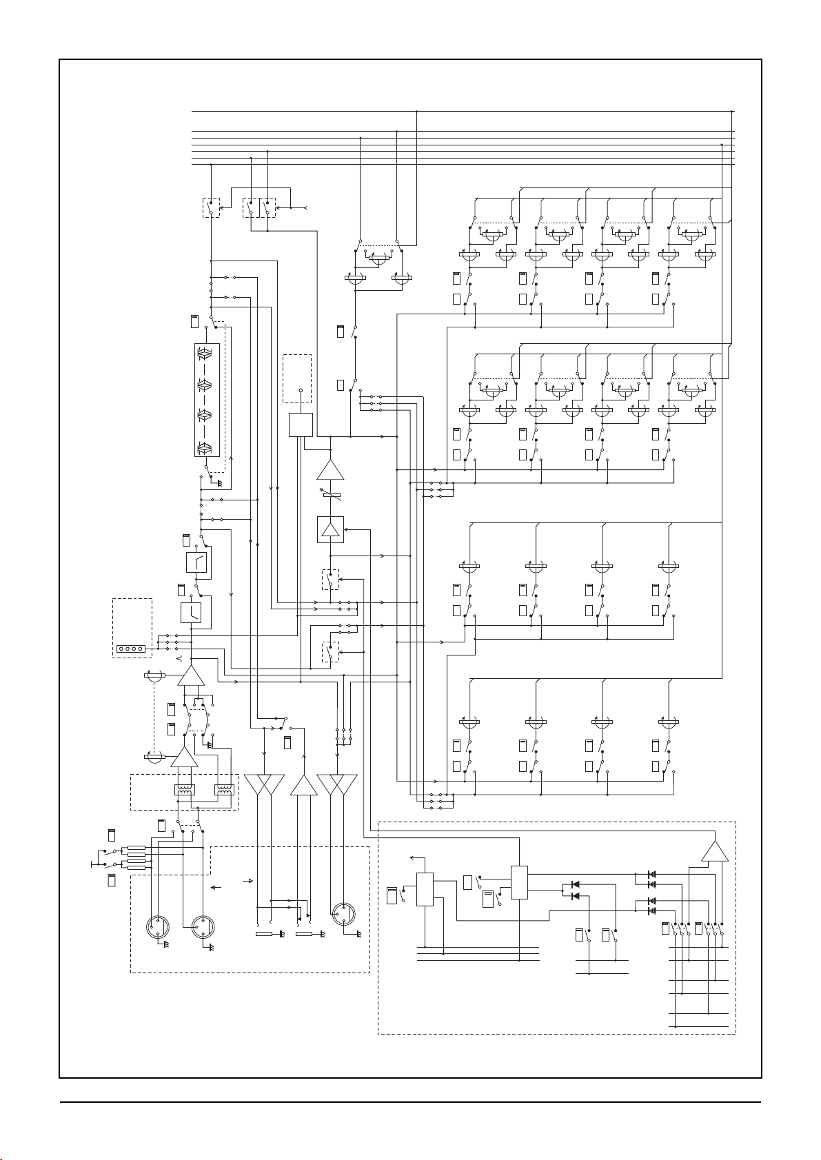
24-Bus Mono Input Module
Page 19

FIVE Monitor Block Diagrams 3.3
SOLO
IP SOLO DET
IP SOLO CLR
FLASH
SOLO
GRP 1-8
PREFADE
SOURCE
SOLO
LOGIC
MUTE
MUTE
LOGIC
1
1
VCA
CONTROL
4B
8B
12B
16B
4A
8A
12A
16A
3A
7A
11A
15A
2A
6A
10A
14A
1A
5A
9A
13A
L
3B
7B
11B
15B
2B
6B
10B
14B
1B
5B
9B
13B
R
+5dB
+5dB
+5dB
+5dB
+5dB
+5dB
+5dB
+5dB
+5dB
+5dB
+5dB
+5dB
+5dB
+5dB
+5dB
+5dB
+5dB
+5dB
+5dB
+5dB
+5dB
PAN
PAN
PAN
PAN
PAN
ONPRE
+20dB
PEAK
DETECT
PEAK LED
(ON INPUT FADER)
L/R
PREFADE
SOURCE
POST
FADE
PRE
FADE
PRE
MUTE
PRE
EQ
FADER
SEND
RET
VCA
MUTEMUTE
DIRECT
OUTPUT
SOURCE
INSERT
RETURN
DIRECT
OUT
+4dBu
+4dBu
INSERT
SEND
INPUT A
INPUT B
A/B
A
PHANTOM POWER
+48V
B
OPTIONAL
MIC/LINE
INPUT TX
SIMPLIFIED
VIEW +
DRILL-OUT
PADS
RNG
-2dBu
IN
20 - 600
1k - 20k
HP
LP
IN
INSERT
PRE EQ
(DEFAULT)
LF LO MID HIMID
4 BAND PARAMETRICEQUALISER
HF
EQ
INSERT
POST EQ
MONO/STE MODE BUS
PFL BUS
AFL LBUS
AFL R BUS
GROUP BUS (1-32)
GRP LBUS
GRP R BUS
SOLO
-6dB
-6dB
FILTERS
METER
SOURCE
INPUT METER
(ON INPUT FADER)
-30/+15dB
SENS
-2 to -70dBu/
+10 to -20dBu
INPUT
REARCON
OPTIONAL
MULTIWAYCONNS
+ DRILL OUTPADS
FOR TRANSFORMER
BALANCING
INSERT
IN
-
+
PREMUTE
SOURCE
PRE EQ
MUTE
ENABLE
+10dB
VCAIS BYPASSED
WHEN NO VCABUS
IS SELECTED
LEVEL
LEVEL
LEVEL
LEVEL
LEVEL
+5dB
+5dB
+5dB
+5dB
+5dB
+5dB
+5dB
+5dB
+5dB
+5dB
+5dB
+5dB
+5dB
STEREO
STEREO
STEREO
STEREO
STEREO
STEREO
STEREO
STEREO
STEREO
STEREO
STEREO
STEREO
STEREO
STEREO
GRP 9-16
PREFADE
SOURCE
STEREO
STEREO
STEREO
ON
ON
ON
ON
ON
ON
ON
ON
ON
ON
ON
ON
ON
ON
ON
ON
PRE
PRE
PRE
PRE
PRE
PRE
PRE
PRE
PRE
PRE
PRE
PRE
PRE
PRE
PRE
PRE
8
8
MUTE GROUP
CONTROLS
GENERATEDBY
MUTE MASTER ASSY
VCACONTROLS
GENERATEDBY
VCAFADER ASSY
MUTE BUS 8
MUTE BUS 1
VCALEVEL 8
VCALEVEL 1
VCAMUTE 8
VCAMUTE 1
VCASOLO 8
VCASOLO 1
MUTE
SAFE
Ø
å
32-Bus Mono Input Module
Page 20

3.4 FIVE Monitor Block Diagrams
å
å
å
å
å
å
å
INPUTMETERS
(ONINPUT
FADERPCB)
-20/+10dB
LEFT
L
R
LINKSDISABLE
RHSPHASE
REVERSE
L
LR
+48V
PHANTOM
INPUT
REARCON
INPUTL
INPUTR
INSERT
SEND
INSERT
SEND
INSERT
RETURN
INSERT
IN
--+
+
INSERT
RETURN
INPUT
FADER
SOLO
SOLO
MUTE
SAFE
MUTE
MUTE
LOGIC
GRP1-8
PREFADE
SOURCE
GRP9-16
PREFADE
SOURCE
POSTFADE
TOMETERS
L L
L
LLL L
L
PRE
EQ
PRE
MUTE
PRE-
MUTE
SOURCE
VCAIS BYPASSED
WHENNO VCA BUS
ISSELECTED
VCAIS BYPASSED
WHENNO VCA BUS
ISSELECTED
VCA
VCA
MUTEMUTE
INPUTL
TOPRE-EQ MUTE RIGHT
SENDR
RETR
LF
LF
IN
20-600
HP
TOPRE-EQ MUTE LEFT
SENDL
RETL
INSERT
PREEQ
(DEFAULT)
LOMID
LOMID
HIMID
HIMID
HF
HF
EQ
INSERT
POSTEQ
INSERT
POSTEQ
PFLBUS
AFLL BUS
AFLR BUS
GRPL BUS
GRPR BUS
MONO/STEMODE BUS
GROUPBUS 1-8A
GROUPBUS 1-8 B
GROUPBUS 9-16 A
GROUPBUS 9-16 B
RHS
LHS
4BAND PARAMETRIC EQUALISER
FILTER
20-600
HP
INSERT
PREEQ
(DEFAULT)
PRE-MUTEL
LHSLHS
INPUTR
PRE-MUTER
PRE-
MUTE
SOURCE
PRE-EQ
MUTE
ENABLE
FADER
PEAK
DETECT
PEAK
DETECT
PEAKLED
(ONINPUT FADER)
PEAKLED
(ONINPUT FADER)
RIGHT
LEFT
SOLO
+20dB
+20dB
FADER
+10dB
+10dB
PRE-EQ
MUTE
ENABLE
MUTE MUTE
RHS RHS
PRE
FADE
POST
FADE
GROUPSEND L & R
PRE
MONOPOST
M
R
L
L
R
M
+5dB
+5dB
+5dB
LEVEL
STEREO
BAL
ON
L/R
PREFADE
SOURCE
R R
R
RRR R
R
MUTEBUS 8
VCALEVEL 8
VCAMUTE 8
VCASOLO 8
VCASOLO 1
VCAMUTE 1
VCALEVEL 1
MUTEBUS 1
MUTEGROUP
CONTROLS
GENERATEDBY
MUTEMASTER ASSY
118
8
VCACONTROLS
GENERATEDBY
VCAFADER ASSY
VCA
CONTROL
PRE ON
ON
STE
L
L
L
+5dB
+5dB
+5dB
+5dB
+5dB
LEVEL
LEVEL
PRE
GROUPSENDS 9-16 (1 OF 8 SHOWN)
ON
L
M
R
STEREO
GROUPSENDS 1-8
(2OF 8 SHOWN)
9-16A
1-8B
9-16B
STEREOMODE
M
R
LEVEL
ODD
EVEN
R
BAL
M
SOLO
LOGIC
IPSOLO DET
IPSOLO CLA
FLASH
+4dBu
LEFT
+4dBu
RIGHT
-2to -70dBu/
+10to -20dBu
R
METER
SOURCE
METER
SOURCE
RNG
RNG
L
R
0
SENS
SENS
OPTIONAL
MIC/LINE
INPUTTX
SIMPLIFIED
VIEW+
DRILL-OUT
PADS
-2dBu
-2dBu
-4.5dB
RIGHT
MNO MNOLR
24-Bus Stereo Input Module
Page 21

FIVE Monitor Block Diagrams 3.5
å
å
å
å
å
å
å
INPUTMETERS
(ONINPUT
FADERPCB)
-20/+10dB
LEFT
L
R
LINKSDISABLE
RHSPHASE
REVERSE
L
L R
+48V
PHANTOM
INPUT
REARCON
INPUTL
INPUTR
INSERT
SEND
INSERT
SEND
INSERT
RETURN
INSERT
IN
--+
+
INSERT
RETURN
INPUT
FADER
SOLO
SOLO
MUTE
SAFE
MUTE
MUTE
LOGIC
GRP1-8
PREFADE
SOURCE
GRP9-16
PREFADE
SOURCE
POSTFADE
TOMETERS
L L
L
L L L L
L
PRE
EQ
PRE
MUTE
PRE-
MUTE
SOURCE
VCAIS BYPASSED
WHENNO VCA BUS
ISSELECTED
VCAIS BYPASSED
WHENNO VCA BUS
ISSELECTED
VCA
VCA
MUTEMUTE
INPUTL
TOPRE-EQ MUTE RIGHT
SENDR
RETR
LF
LF
IN
20-600
HP
TOPRE-EQ MUTE LEFT
SENDL
RETL
INSERT
PREEQ
(DEFAULT)
LOMID
LOMID
HIMID
HIMID
HF
HF
EQ
INSERT
POSTEQ
INSERT
POSTEQ
PFLBUS
AFLL BUS
AFLR BUS
GRPL BUS
GRPR BUS
MONO/STEMODE BUS
GROUPBUS 1-8A
GROUPBUS 1-8 B
GROUPBUS 9-16 A
GROUPBUS 9-16 B
RHS
LHS
4BAND PARAMETRIC EQUALISER
FILTER
20-600
HP
INSERT
PREEQ
(DEFAULT)
PRE-MUTEL
LHSLHS
INPUTR
PRE-MUTER
PRE-
MUTE
SOURCE
PRE-EQ
MUTE
ENABLE
FADER
PEAK
DETECT
PEAK
DETECT
PEAKLED
(ONINPUT FADER)
PEAKLED
(ONINPUT FADER)
RIGHT
LEFT
SOLO
+20dB
+20dB
FADER
+10dB
+10dB
PRE-EQ
MUTE
ENABLE
MUTE MUTE
RHS RHS
PRE
FADE
POST
FADE
GROUPSEND L &R
PRE
MONOPOST
M
R
L
L
R
M
+5dB
+5dB
+5dB
LEVEL
STEREO
BAL
ON
L/R
PREFADE
SOURCE
R R
R
R R R R
R
MUTEBUS 8
VCALEVEL 8
VCAMUTE 8
VCASOLO 8
VCASOLO 1
VCAMUTE 1
VCALEVEL 1
MUTEBUS 1
MUTEGROUP
CONTROLS
GENERATEDBY
MUTEMASTER ASSY
118
8
VCACONTROLS
GENERATEDBY
VCAFADER ASSY
VCA
CONTROL
PRE ON
L
L
L
+5dB
+5dB
+5dB
+5dB
+5dB
+5dB
LEVEL
LEVEL
PRE
GROUPSENDS 9-16 (1 OF 8 SHOWN)
ON
L
M
R
STEREO
GROUPSENDS 1-8
(1OF 8 SHOWN)
STEREO
1-8A
9-16A
1-8B
9-16B
STEREOMODE
STEREOMODE
BAL
M
R
R
R
BAL
M
M
SOLO
LOGIC
IPSOLO DET
IPSOLO CLA
FLASH
+4dBu
LEFT
+4dBu
RIGHT
-2to -70dBu/
+10to -20dBu
R
METER
SOURCE
METER
SOURCE
RNG
RNG
L
R
0
SENS
SENS
OPTIONAL
MIC/LINE
INPUTTX
SIMPLIFIED
VIEW+
DRILL-OUT
PADS
-2dBu
-2dBu
-4.5dB
RIGHT
MNO MNOL R
32-Bus Stereo Input Module
Page 22

3.6 FIVE Monitor Block Diagrams
Ø
Ø
DRILL-OUT PADS
L
FADER
B OUTPUT
OPTIONALEDAC
OR TRANSFORMER
PARTOF
UPPER MASTER REARCON
B
GROUP
OUTPUT
TB DIM
+4dBu
OP SOLO CLR
OP SOLO INH
OP SOLO DET
TOMATRIX
METER IN
OVERBRIDGE
MIDI
CONTROL
SOLO
LOGIC
SOLO
SIGNAL
-30dBu
-2dBu
MUTE
INSERT
+
-
INSERT
RETURNSEND
PARTOF
LOWER
MASTER
REARCON
OPTIONAL
EXTERNAL
INPUT
SELECTION
EXTERNAL
SOURCE
SELECTION
GRPR
GRPL
GRP10B
GRP9B
GRP9A
GRP7A
GRP5A
GRP3A
GRP1A
TALKBACK
OUTPUTBUS
GRP 8A
GRP 6A
GRP 4A
GRP 2A
GRP8B
GRP6B
GRP4B
GRP2B
GRP7B
GRP5B
GRP3B
GRP1B
GRP 10A
EXTL
EXTR
EXT
DRILL-OUTPADS
DRILL-OUTPADS
DRILL-OUTPADS
OPTIONALEDAC
OR TRANSFORMER
OPTIONALEDAC
OR TRANSFORMER
+4dBu/
-10dBv
+
+
-
-
OPTIONALEDAC
OR TRANSFORMER
OPTIONAL
MULTPIN
CONNECTOR
PANEL
OPTIONAL
INDIVIDUAL
MATRIX
EXTERNAL
INPUT
OPTIONAL
MULTPIN
CONNECTOR
MATRIX
EXTERNAL
INPUTL
MATRIX
EXTERNAL
INPUTR
PARTOF
LINK REARCON
PARTOF
POWER
DISTRIBUTION
PCB
OPTIONAL
BUFFER
AMP
EXT
MONO
OUT
MATRIX
OUTPUT
MATRIX
MUTE LOGIC
PARTOF
LOWER MASTER
REARCON
FLASH
MUTE ALLOUTPUTS
TB DIM
MUTE
MATRIX
MASTER
MATRIX
+10dB
-2dBu
+4dBu
6dBTBDIM
OPTIONAL
E DAC OR Tx
DRILL-OUTPADS
TO ALLMATRIX
SECTIONS AND
GROUP METER
IN OVERBRIDGE
DIM
MUTE
TB
TALKBACK
-2dBu
+10dB
OUT
INSERT
+
6dB
-2dBu
+4dBu
ALT
GLOBAL
STEREO
R
INSERT
RETURNSEND
POSTMUTE
POSTMUTE
POSTFADE
POSTFADE
PREFADE
PREFADE
±10dB
±10dB
MIDI
CONTROL
MIDI
CONTROL
SOLO
TRIM
SOLO
TRIM
GLOBAL
STEREO
STEREO
STEREO
STEREO
MONO
MONO
MONO
-4.5dB
-6dB
-6dB
STEREO
MONO
MONO
MONO
-6dB
-6dB
-4.5dB
ALT
ALT
SOLO
LOGIC
GLOBAL
GLOBAL
STEREO
AGROUP
MUTE LOGIC
TO ALLMATRIX
SECTIONS AND
GROUP METER
IN OVERBRIDGE
DIM
MUTE
INSERT
INSERT
AOUTPUT
GROUP BUS-32
MONO/STE MODE BUS
ALTPFL
ALTAFL L
ALTAFL R
PFL
AFLL
AFLR
GRP L
GRP R
PARTOF
UPPER
MASTER
REARCON
RETURNSEND
+
-
OUT
FADER
+10dB
-2dBu
-2dBu
L
OPTIONALEDAC
OR TRANSFORMER
OPTIONALEDAC
OR TRANSFORMER
AGROUP
EXTERNAL
INPUT
B GROUP
EXTERNAL
INPUT
PARTOF
LINK REARCON
DRILL-OUT PADS
DRILL-OUT PADS
-
-
+
+
R
+4dBu
6dB
PARTOF
UPPER MASTER REARCON
FLASH
MUTE ALLOUTPUTS
A
GROUP
OUTPUT
+4dBu
DRILL-OUT PADS
OPTIONALEDAC
OR TRANSFORMER
MUTE
B GROUP
MUTE LOGIC
STE
MUTE
SOLO
LOGIC
SOLO
SOLO
TB
TALKBACK
TB DIM
OPSOLO CLR
OPSOLO INH
OPSOLO DET
PARTOF
UPPER
MASTER
REACON
å
å
å
å
å
å
OPTIONAL
MULTIPIN
CONNECTOR
OPTIONAL
MULTIPIN
CONNECTOR
OPTIONAL
MULTIPIN
CONNECTOR
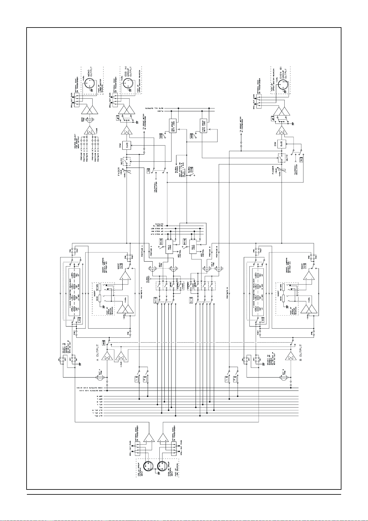
32-Bus Output Module
Page 23

FIVE Monitor Block Diagrams 3.7
TO WEDGE METERS
IN OVERBRIDGE
OPTIONALEDAC
OR TRANSFORMER
OPTIONALEDAC
OR TRANSFORMER
OPTIONALEDAC
OR TRANSFORMER
DRILL-OUT PADS
OPTIONALEDAC
OR TRANSFORMER
PHONES OUTPUT
(UPPER MASTER
REARCON)
PHONES OUTPUT
(FADERPANEL)
PHONES
POWER AMP
PARTOF LOWER
MASTER REARCON PCB
WEDGE R
OUTPUT
WEDGE L
OUTPUT
POWER
AMP
ALTWEDGE
LOUTPUT
ALTWEDGE
LOUTPUT
PARTOF LOWER
MASTER REARCON PCB
PARTOF LOWER
MASTER REARCON PCB
PARTOF LOWER
MASTER REARCON PCB
PARTOF POWER
DISTRIBUTION PCB
SUPPLY
RAIL
SENSE
CIRCUITRY
PSU 1
PSU 2
OSC
OUTPUT
PSU RAIL
INDICATORS
+ / -17V
+5V
+48V
TALKBACK
TB DIM
+4dBu
+4dBu
MAIN WEDGE/
ALTSOLO
PRE
SRC
ALT
LEVEL
+10dB
ALT
ON
PHONES
LEVEL
PHONES
DIM
TALKBACK
TO PHONES
DRILL-OUT PADS
DRILL-OUT PADS
DRILL-OUT PADS
WEDGE
DIM
WEDGE
DIM
FOH TB
OUTPUT
+4dBu
TALKBACKTO PHONES
WEDGE DIM
PHONES DIM
TO OUTPUTS
VIATB
ON
TB LOGIC
LEVEL
FREQ
OSC
X10
OSCILLATORON
OSC TO
OUTPUTS 25-32 ENABLE
PINK
ON
ON
OSC
TO
BUSSES
OSC
TO
OUTPUT
FOH
TB
LEVEL
15v
CONTROL
VOLTAGE
ENABLE
-2dBu
-30
PAD
-20 TO -50dBu
FOH
TB
TB MIC
TB MIC
FRONT PANEL
XLR
PARTOF LOWER
MASTER REARCON
PCB
FOH TB
INPUT
+
_
+48V
PHANTOM
+48V
EXT
DIM
DIM
DIM
DIM
DIM
DIM
FADER
WEDGE
WEDGE
INSERT
WEDGE
MONO
SOURCE
WEDGE
MONO
SOURCE
ON
IN R
L
-2dBu
-2dBu
+4dBu
+4dBu
-2dBu
-2dBu
-2dBu
GRP R
POSTMUTE
GRP L&R
TO WEDGE
ENABLE
INPUT SOLO DETECT
OUTPUT SOLO DETECT
OUTPUT SOLO INHIBIT
INPUT SOLO CLEAR
OUTPUT SOLO CLEAR
AUTO
CANCEL
SOLO
SOLO
LOGIC
CLEAR
INPUT
PRIORITY
ONON
INSERT
INSERT
GRP L
POSTMUTE
±10dB
PFL
TRIM
PFL
PFL
AFLL
AFLR
ALTPFL
ALTAFL L
ALTAFL R
GRP L
GRP R
OUTPUTS1-24
OUTPUTS 25 - 32
AFLL
AFLR
MASTER
MODE
PFL/AFL
PARTOF
LINK REARCON
EXT PFL
INPUT
+
+
+
_
_
_
EXT AFLL
INPUT
EXT AFLR
INPUT
AFLR
OUTPUT
AFLL
OUTPUT
PFL
OUTPUT
ALT
PFL
å
å
å
å
å
å
å
å
å
ALT
AFL
L
R
ALT
AFL
PARTOF LOWER
MASTER REARCON
PARTOF UPPER
MASTER REARCON PCB
SEND
SEND
RETURN
+
_
RETURN
+
_
WEDGE
DIM
WEDGE
DIM
20dB
20dB
15dB
15dB
20dB
20dB
+10dB
+10dB
+4dBu
+4dBu
Master Module (1)
Page 24

3.8 FIVE Monitor Block Diagrams
Ø
Ø
DRILL-OUTPADS
R OUTPUT
FADER
OPTIONALEDAC
OR TRANSFORMER
PARTOF
UPPER MASTER REARCON
GROUPR
OUTPUT
+4dBu
DIM
TOALL MATRIX
SECTIONS AND
WEDGE INPUT
MUTE
TB
-2dBu
+10dB
OUT
INSERT
+
6dB
-2dBu
+4dBu
GLOBAL
STEREO
INSERT
RETURNSEND
POSTFADE
POSTFADE
±10dB
±10dB
PREFADE
PREFADE
MIDI
CONTROL
MIDI
CONTROL
SOLO
TRIM
SOLO
TRIM
GLOBAL
STEREO
STEREO
STEREO
STEREO
MONO
MONO
MONO
-4.5dB
-6dB
-6dB
STEREO
MONO
MONO
MONO
-4.5dB
ALT
ALT
SOLO
LOGIC
GLOBAL
GLOBAL
STEREO
GROUPL
MUTE LOGIC
TOALL MATRIX
SECTIONS AND
WEDGE INPUT
DIM
MUTE
INSERT
OPTIONAL
MULTIPIN
CONNECTOR
OPTIONAL
MULTIPIN
CONNECTOR
INSERT
LOUTPUT
OUTPUTS1-32
GRPMONO/STE MODE BUS
ALTPFL
ALTAFL L
ALTAFL R
PFL
AFLL
AFLR
GRPL
GRPR
PARTOF
UPPER
MASTER
REARCON
RETURNSEND
+
-
OUT
FADER
+10dB
-2dBu
-2dBu
OPTIONALEDAC
OR TRANSFORMER
OPTIONALEDAC
OR TRANSFORMER
GROUPL
EXTERNAL
INPUT
GROUPR
EXTERNAL
INPUT
PARTOF
LINK REARCON
DRILL-OUTPADS
DRILL-OUTPADS
-
-
+
+
+4dBu
6dB
PARTOF
UPPER MASTER REARCON
FLASH
MUTE ALLOUTPUTS
GROUPL
OUTPUT
+4dBu
DRILL-OUTPADS
OPTIONALEDAC
OR TRANSFORMER
MUTE
GROUPR
MUTE LOGIC
STE
MUTE
SOLO
LOGIC
SOLO
SOLO
TB
OPSOLO CLR
OPSOLO INH
OPSOLO DET
TB DIM
TALKBACK
PARTOF
UPPER
MASTER
REACON
å
å
å
å
Master Module (2)
Page 25

FIVE Monitor Block Diagrams 3.9
FLASH BUS
OSCILLATOR
NOMINAL
SOLO
LOGIC
MUTE MASTER
FX RACK
CONTROLLER
MODULE
MIDI
SOLO REMOTE
IN
IN
COMMS LINK/MIDI REARCON
OUT
OUT
MIDI MERGE
PROCESSOR
LOGIC TRIGGER
FROM OUTPUT
&MATRIX
SOLO BUTTONS
VCAMUTE 1-8
VCALEVEL 1-8
VCASOLO1-8
MUTE ALLOUTPUTS
MUTE GROUP 1-8
VCABUS1-8
FLASH
IP SOLO CLEAR
OP SOLO CLEAR
IP SOLO DET
OP SOLO DET
OP SOLO INHIBIT
THRU
MUTE GROUP 1IN
MUTE GROUP 1 OUT
VCA1 OUT
VCASOLO 1 OUT
VCAMUTE 1 OUT
IP SOLO DETIN
IP SOLO CLEAR IN
OP SOLO CLEAR IN
OP SOLO CLEAR OUT
OP SOLO INHIBITOUT
IP SOLO CLEAR OUT
OP SOLO DETIN
VCA1IN
VCASOLO 1 IN
VCAMUTE 1 IN
IP SOLO DETOUT
IP SOLO CLEAR OUT
OP SOLO CLEAR OUT
OP SOLO INHIBITIN
IP SOLO CLEAR IN
OP SOLO CLEAR IN
OP SOLO DETOUT
MUTE GROUP 1 LINK SHOWN
MUTE GROUP 2 - 8 IDENTICAL
VCA1 LINK SHOWN
VCA2 - 8 IDENTICAL
+
_
M1 SHOWN
M2 - M8 ARE IDENTICAL
CONSOLE
LINK IN
PARTOF
LINK REARCON
CONSOLE
LINK OUT
PARTOF
LINK REARCON
M1
MUTE
ALL
OUTPUTS
MUTE
SOLO
VCA1
FADER
VCAFADER 1
VCA2 - B ARE IDENTICAL
VCAVOLTAGE
REFERENCES
VCADC
PARTOF
MASTER MODULE
PARTOF
COMMS LINK/MIDI REARCON
COMMS LINK
CALL
SIGNAL
DETECT
CONSOLE
LAMPS FLASH
OSCILLATOR
CONSOLE
LAMPS
DIMMER
CONSOLE
LAMPS
PARTOF
MASTER
MODULE
LAMP
DIM
IN
OUT
MUTE FLASH
DISABLE
(HIDDEN SWITCH)
å
Master Module (3)
Page 26
3.10 FIVE Monitor Block Diagrams
EQ Output
Page 27

FIVE Monitor Functional Description 4.1
FFIIVVEE MMoonniittoorr
FFuunnccttiioonnaall DDeessccrriippttiioonn
44
Page 28

FIVE Monitor Functional Description 4.2
kk
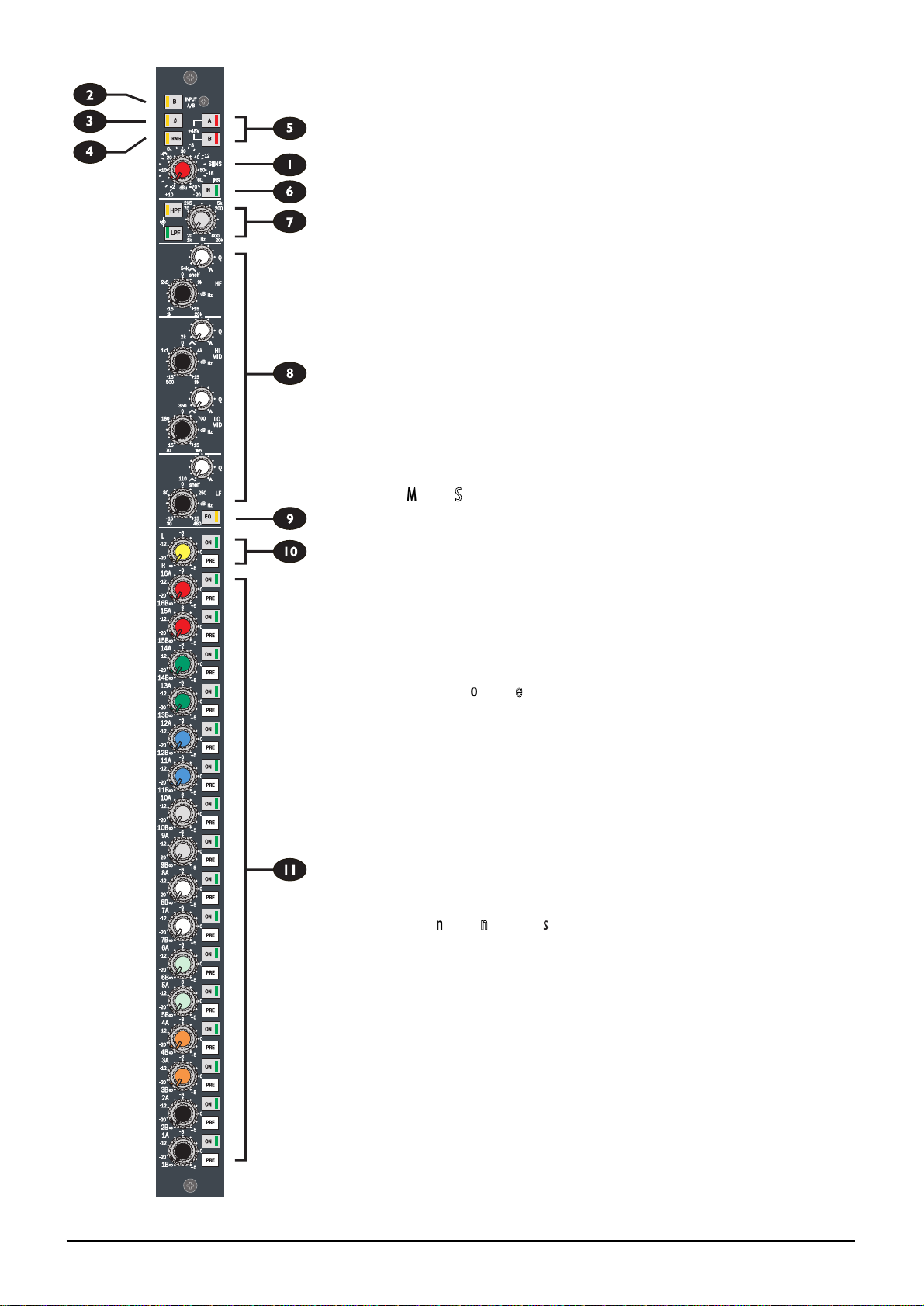
IInnppuutt MMoodduullee
1
SSEENNSS ((SSeennssiittiivviittyy))
The SENSitivity Control adjusts the level of the signal which is present on the
Input XLRs. The input can handle mic or line level signals up to +30dBu, with the
RANGE switch (see below) selecting high or low sensitivity.
2
IINNPPUUTT AA//BB -- BB
Every input has A and B XLR inputs, allowing a large number of inputs to be con-
nected to the console without repatching. Normally the A input is active, unless
the B switch is pressed to select the alternative input.
3
ØØ ((PPhhaassee))
The PHASE switch reverses the phase of the selected input signal, to compensate
for incorrect wiring or mic placement. The switch is internally illuminated when
phase is reversed.
4
RRNNGGEE ((RRaannggee))
The RNGE (Range) switch selects between an input range of -2dBu to -70dBu
(switch released), and +10dBu to -20dBu (switch pressed and lit), enabling both
mic and line level signals to be handled by a common input stage.
CAUTION: Phantom power should not be switched on when unbalanced
sources are connected to the XLR input.
5
4488VV AA aanndd BB
The 48V switches, when depressed, place 48V phantom power on pins 2 & 3 of
the respective XLRs. Integral LEDs illuminate when the phantom power is on.
6
IINNSS ((IInnsseerrtt PPooiinntt))
The Insert Point may be switched in circuit by the INS switch. The insert uses sep-
arate balanced jacks for send and return. It is normally positioned after the filter
and before the equaliser, but can be repositioned using internal jumpers to be
post-EQ if required. The insert is in-circuit when the switch is illuminated.
7
HHPPFF ((HHiigghhppaassss FFiilltteerr))
Two sweepable filters are provided, offering the capability of cleaning up both
ends of the input signal, minimising the amount of corrective EQ which needs to
be applied.
The High-pass Filter (HPF) control (upper knob) sets the cutoff (-3dB) frequency
of the High-pass filter: it is adjustable between 20Hz and 600Hz. The control also
has a built-in switch to switch the filter out of circuit when rotated fully anticlock-
wise.
The Low-pass Filter (LPF) control (lower knob) sets the cutoff (-3dB) frequency
of the Low-pass filter: it is adjustable between 1kHz and 20kHz. The control also
has a built-in switch to switch the filter out of circuit when rotated fully anticlock-
wise.
8
EEQQ
The EQ section comprises four fully parametric bands, with adjustable Q. The EQ
is enabled when the EQ switch is pressed, and bypassed when the switch is
released. The EQ is active when the EQ switch is illuminated.
Each section has a dual concentric control providing 15dB boost or cut (upper
knob) at a variable frequency (lower knob) and a separate Q control.
24-bus console
Page 29
FIVE Monitor Functional Description 4.3
HHFF
The HF section is fully sweepable from 1kHz to 20kHz. Q is variable from 0.5 to
3.0, or the band may be switched to a shelving response by turning the Q control
fully anticlockwise.
HHMMFF
The HMF spans the range 500Hz to 8kHz. Q is variable from 0.5 to 3.0.
LLMMFF
The LMF spans the range 70Hz to 1.5kHz. Q is variable from 0.5 to 3.0.
LLFF
The HF section is fully sweepable from 30Hz to 480Hz. Q is variable from 0.5 to
3.0, or the band may be switched to a shelving response by turning the Q control
fully anticlockwise.
9
EEQQ
The EQ section is active when the EQ switch is pressed, and bypassed when the
switch is released, allowing easy A/B comparison of the signal with or without EQ.
0
LL//RR MMoonniittoorr SSeennddss
A dual-concentric control routes the signal to the L/R output (on the lower section
of the Master Module). The control may either be configured as two mono sends
(Left and Right), or, if the Global Mode STE switch on the output section on the
Master module is pressed, the send becomes a stereo pair, with the top knob
being send level, and the lower knob being a PAN control. The sends are muted
unless the ON switch is pressed, and may be switched pre-fader by pressing the
PRE switch. The pre-fade source may be configured as pre-fade/post-mute, pre-
mute or pre-EQ/pre-insert using internal jumpers. (see chapter 2).
q
MMoonnoo//SStteerreeoo MMoonniittoorr SSeennddss
The sends to outputs 9-16 (24-bus consoles) or 1-16 (32-bus consoles) are on dual
concentric pots, and each row can be configured at the touch of a button as either
a stereo send with level on the top knob and pan on the lower, or a pair of mono
sends. These pairs of mixes are controlled by the faders in the output modules,
and are labelled 1A & B (8A & B on 24-bus consoles)to 16A and B. Stereo mode is
selected by pressing the Global Mode STE button on the respective output mod-
ule. The sends are muted unless the ON switch is pressed, and may be switched
pre-fader by pressing the PRE switch. The pre-fade source for sends 9-16 may be
configured as pre-fade/post-mute, pre-mute or pre-EQ/pre-insert using internal
jumpers. (see chapter 2).
w
MMoonnoo MMoonniittoorr SSeennddss
(24-bus consoles only)
The lower 8 sends on 24-bus consoles are configured as full-time mono sends,
using single pots. The output modules for these mixes are similar to the output
modules for stereo pairs of outputs, except the Global Mode STE switch is omit-
ted, and the modules comprise two separate output sections. The sends are
muted unless the ON switch is pressed, and may be switched pre-fader by press-
ing the PRE switch. The pre-fade source for sends 1-8 may be configured as pre-
fade/post-mute, pre-mute or pre-EQ/pre-insert using internal jumpers. (see chap-
ter 2).
e
FFaaddeerr
A high-quality 100mm channel fader controls the level to all busses, and has 10dB
of gain when full up as well as an expanded scale around the critical unity gain area,
for maximum resolution.
32-bus console
Page 30
FIVE Monitor Functional Description 4.4
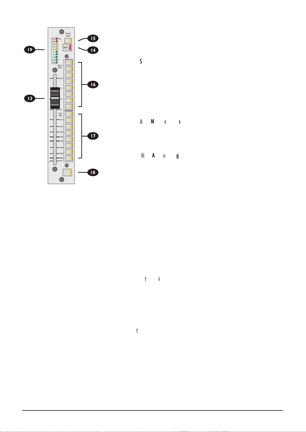
Rr
MMUUTTEE
The Channel MUTE switch mutes all feeds from the input channel, and can be
remotely controlled by the consoles Mute Master section, allowing creation of up
to 8 mute groups. The integral LED illuminates when the Mute is active.
t
MMUUTTEE SSAAFFEE
A semi-recessed Mute SAFE switch allows the channel to be prevented from
remote muting by mute groups, but still allows it to be locally muted. Safe mode
is selected when the switch is pressed and internally illuminated.
MUTE SAFE is particularly useful for protecting key channels and their associated
FX returns from accidental Muting, or for over-riding any remote muting when a
problem occurs during a show and conventional manual control is temporarily
required.
yI
MMUUTTEE AASSNN ((MMuuttee GGrroouupp AAssssiiggnnmmeenntt))
Each input channel can be assigned to any combination of 8 mute groups, using the
recessed switch bank next to the fader. The corresponding Mute Master buttons
are located on the Master module.
uI
VVCCAA AASSNN ((VVCCAA GGrroouupp AAssssiiggnnmmeenntt))
A bank of 8 latching VCA Assign switches with internal LEDs allow the channel to
be assigned to any of the eight VCA Groups. Any combination of assignments is
possible. When no VCA is assigned, the VCA element itself is switched out of the
signal path, to maximise performance. MUTEs or SOLOs on the VCA Group
Master Faders will activate the MUTE or SOLO respectively on any assigned input
channels, allowing groups of inputs to be controlled together with a single button
press.
i
SSOOLLOO
The SOLO button is conveniently located below the fader, and provides a mono
PFL or stereo AFL feed to the engineers headphones or monitors or triggers a
destructive SOLO-IN-PLACE, depending on the mode selection at the Master
section. The SOLO button can also be activated remotely from a VCA SOLO but-
ton, if the channel is assigned to a VCA Group. Intercancel or additive soloing is
possible, with or without Input Priority, and solos can be cleared with a single but-
ton press (SOLO CLEAR) at the master section. The integral LED illuminates to
indicate that a SOLO is active.
o
LLEEDD iinnppuutt mmeetteerriinngg
The channel is fitted with a 10-segment peak-reading bargraph meter, positioned
next to each fader for maximum visibility and giving immediate and graphic indica-
tion of incoming (pre-EQ) signals. The top (red) LED in the bar is configured as a
Peak LED, and monitors the signal path in three places, (input, pre-Mute and post-
fader) giving warning that the signal is exceeding +20dBu. The meter point is
jumper-selectable to be post-fader if required (see Chapter 2).
DDiirreecctt OOuuttppuutt
A balanced direct output is available on a male XLR on the rear panel. This is fed
from a pre-fade signal which can be jumper selectable to be pre or post-EQ, and
pre or post-mute, or may be jumper-selected as post-fade.
1
2
3
4
7
6
7
8
1
2
3
4
7
6
7
8
SOLO
Page 31
FIVE Monitor Functional Description 4.5
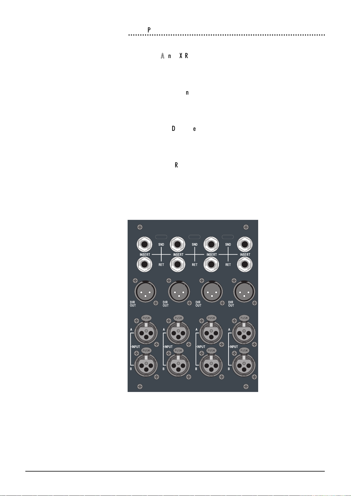
RReeaarrccoonn PPaanneell
The connections on the rearcon panel are as follows:
IINNPPUUTT AA aanndd BB XXLLRR
Pin 1 Gnd (Screen)
Pin 2 Hot (In-phase signal)
Pin 3 Cold(Out-of-phase signal)
DDIIRREECCTT OOUUTT
(Balanced)
Pin 1 Gnd (Screen)
Pin 2 Hot (In-phase signal)
Pin 3 Cold(Out-of-phase signal)
IINNSSEERRTT SSEENNDD
(Balanced)
Tip Hot (In-phase signal)
Ring Cold (Out-of-phase signal)
Sleeve Gnd(screen)
IINNSSEERRTT RREETTUURRNN
(Balanced)
Tip Hot (In-phase signal)
Ring Cold (Out-of-phase signal)
Sleeve Gnd(screen)
Page 32

FIVE Monitor Functional Description 4.6
OOppttiioonnaall SStteerreeoo IInnppuutt MMoodduullee
The optional Stereo module has Left and Right input XLRs and the module may
either be configured as a stereo signal path or the Left or Right signals may be fed
in mono to both sides of the input.
1
SSEENNSS ((SSeennssiittiivviittyy))
The SENSitivity Control adjusts the level of the signal which is present on the
Input XLRs. The input can handle mic or line level signals up to +30dBu, with
individual RANGE switches (see below) for L and R selecting high or low sensitivi-
ty.
2
RRNNGG ((RRaannggee)) LL//RR
The RNGE (Range) switches selects between an input range of -2dBu to -70dBu
(switch released), and +10dBu to -20dBu (switch pressed and lit), enabling both
mic and line level signals to be handled by each side of the input.
CAUTION: Phantom power should not be switched on when unbalanced
sources are connected to the XLR inputs.
3
ØØ ((PPhhaassee))
The PHASE switch reverses the phase of the Left input signal when pressed, to
compensate for incorrect wiring or mic placement. The switch is internally illumi-
nated when phase is reversed.
4
4488VV LL aanndd RR
The 48V switches, when depressed, place 48V phantom power on pins 2 & 3 of
the respective Left and Right input XLRs. Integral LEDs illuminate when the phan-
tom power is on.
CAUTION: Phantom power should not be switched on when unbalanced
sources are connected to the XLR inputs.
5
MMNNOO ((MMoonnoo)) LL aanndd RR
The MNO L and R switches select the Left or Right sides of the source signal (post
input amp) and feeds either or both signals to both channels of the module. This is
very useful when a single mono source is attached to just one leg of the input, but
is required to feed both sides of an Output pair which has been globally configured
as Stereo.
6
IINNSS ((IInnsseerrtt PPooiinntt))
The Insert Point may be switched in circuit by the INS switch. The insert uses sep-
arate balanced jacks for send and return. It is normally positioned after the filter
and before the equaliser, but can be repositioned using internal jumpers to be
post-EQ if required. The insert is in-circuit when the switch is illuminated.
7
HHPPFF ((HHiigghhppaassss FFiilltteerr))
A sweepable High-pass Filter (HPF) control sets the cutoff (-3dB) frequency of the
High-pass filter: it is adjustable between 20Hz and 600Hz. The filter is active when
the IN switch is pressed, and bypassed when the switch is released, allowing easy
A/B comparison of the signal with and without the extreme low end content.
24-bus console
Page 33

FIVE Monitor Functional Description 4.7
8
EEQQ
The stereo EQ section comprises four fully parametric bands, with adjustable Q.
Each section has a dual concentric control providing 15dB boost or cut (upper
knob) at a variable frequency (lower knob) and a separate Q control.
HHFF
The HF section is fully sweepable from 1kHz to 20kHz. Q is variable from 0.5 to
3.0, or the band may be switched to a shelving response by pressing the associated
SHELF switch.
HHMMFF
The HMF spans the range 500Hz to 8kHz. Q is variable from 0.5 to 3.0.
LLMMFF
The LMF spans the range 70Hz to 1.5kHz. Q is variable from 0.5 to 3.0.
LLFF
The HF section is fully sweepable from 30Hz to 480Hz. Q is variable from 0.5 to
3.0, or the band may be switched to a shelving response by pressing the SHELF
switch.
9
EEQQ
The EQ section is active when the EQ switch is pressed, and bypassed when the
switch is released, allowing easy A/B comparison of the signal with or without EQ.
0
LL//RR MMoonniittoorr SSeennddss
A dual-concentric control routes the signal to the L/R output (on the lower section
of the Master Module).
The send is globally switched into stereo as on the mono input, but in a slightly dif-
ferent way. In stereo mode, the control works as upper=level, lower=balance,
with the left half of the module routed to the L bus and the right half to the R bus.
The balance control then gives unity to both sides when in centre, and +4.5dB to
one side when fully turned that way, and OFF to the other side.
In mono mode, the upper and lower knobs are both level controls, the upper
feeding a mono sum (pre or post-fade as selected by the PRE switch) to the L bus
and the lower a mono sum to the R bus, with a gain of 5dB at full rotation.
The send is muted unless the ON switch is pressed, and may be switched pre-
fader by pressing the PRE switch. The pre-fade source may be configured as pre-
fade/post-mute, pre-mute or pre-EQ/pre-insert using internal jumpers. (see chap-
ter 2).
q
MMoonnoo//SStteerreeoo MMoonniittoorr SSeennddss
The sends to outputs 9-16 (24-bus consoles) or 1-16 (32-bus consoles) are on dual
concentric pots, and each row can be configured at the touch of a button as either
a stereo send or a pair of mono sends. In stereo mode, the controls work as
upper=level, lower=balance, with the left half of the module routed to the L bus
and the right half to the R bus. The balance control then gives unity to both sides
when in centre, and +4.5dB to one side when fully turned that way, and OFF to
the other side.
In mono mode, the upper and lower knobs are both level controls, the upper
feeding a mono sum (pre or post-fade as selected by the PRE switch) to the L bus
and the lower a mono sum to the R bus, with a gain of 5dB at full rotation.
32-bus console
Page 34

FIVE Monitor Functional Description 4.8
1
2
3
4
7
6
7
8
1
2
3
4
7
6
7
8
SOLO
L
R
These pairs of mixes are controlled by the faders in the output modules, and are
labelled 1A & B (8A & B on 24-bus consoles)to 16A and B. Stereo mode is select-
ed by pressing the Global Mode STE button on the respective output module.
The sends are muted unless the ON switch is pressed, and may be switched pre-
fader by pressing the PRE switch. The pre-fade source for sends 9-16 may be
configured as pre-fade/post-mute, pre-mute or pre-EQ/pre-insert using internal
jumpers. (see chapter 2).
w
MMoonnoo MMoonniittoorr SSeennddss
(24-bus consoles only)
The lower 8 sends on 24-bus consoles are configured as either individual sends,
each fed with a mono sum of the stereo signal, or (by pressing the STE switch) as
stereo pairs, with odd numbers feeding the L busses and even numbers feeding
the R busses. This switching is done in four blocks of two sends, i.e. there is a STE
switch for every pair of mono sends. The PRE switches also affect adjacent pairs
of sends.
The output modules for these mixes are similar to the output modules for stereo
pairs of outputs, except the Global Mode STE switch is omitted, and the modules
comprise two separate output sections. The sends are muted unless the ON
switch is pressed, and may be switched pre-fader by pressing the PRE switch.
The pre-fade source for sends 1-8 may be configured as pre-fade/post-mute, pre-
mute or pre-EQ/pre-insert using internal jumpers. (see chapter 2).
e
FFaaddeerr
A high-quality 100mm channel fader controls the level to all busses, and has 10dB
of gain when full up as well as an expanded scale around the critical unity gain
area, for maximum resolution.
Rr
MMUUTTEE
The Channel MUTE switch mutes all feeds from the input channel, and can be
remotely controlled by the consoles Mute Master section, allowing creation of up
to 8 mute groups. The integral LED illuminates when the Mute is active.
t
MMUUTTEE SSAAFFEE
A semi-recessed Mute SAFE switch allows the channel to be prevented from
remote muting by mute groups, but still allows it to be locally muted. Safe mode
is selected when the switch is pressed and internally illuminated. MUTE SAFE is
particularly useful for protecting key channels and their associated FX returns
from accidental Muting, or for over-riding any remote muting when a problem
occurs during a show and conventional manual control is temporarily required.
yI
MMUUTTEE AASSNN ((MMuuttee GGrroouupp AAssssiiggnnmmeenntt))
Each input channel can be assigned to any combination of 8 mute groups, using
the recessed switch bank next to the fader. The corresponding Mute Master but-
tons are located on the Master module.
uI
VVCCAA AASSNN ((VVCCAA GGrroouupp AAssssiiggnnmmeenntt))
A bank of 8 latching VCA Assign switches with internal LEDs allow the channel to
be assigned to any of the eight VCA Groups. Any combination of assignments is
possible. When no VCA is assigned, the VCA element itself is switched out of the
signal path, to maximise performance. MUTEs or SOLOs on the VCA Group
Master Faders will activate the MUTE or SOLO respectively on any assigned input
channels, allowing groups of inputs to be controlled together with a single button
press.
Page 35

FIVE Monitor Functional Description 4.9
i
SSOOLLOO
The SOLO button is conveniently located below the fader, and provides a mono
PFL or stereo AFL feed to the engineers headphones or monitors depending on
the mode selection at the Master section. The SOLO button can also be activated
remotely from a VCA SOLO button, if the channel is assigned to a VCA Group.
Intercancel or additive soloing is possible, with or without Input Priority, and solos
can be cleared with a single button press (SOLO CLEAR) at the master section.
The integral LED illuminates to indicate that a SOLO is active.
o
LLEEDD iinnppuutt mmeetteerriinngg
The channel is fitted with a dual 5-segment peak-reading bargraph meter, posi-
tioned next to each fader for maximum visibility and giving immediate and graphic
indication of incoming (pre-EQ) signals. The top (red) LED in the bar is configured
as a Peak LED, and monitors the signal path in three places, (input, pre-Mute and
post-fader) giving warning that the signal is exceeding +20dBu. The meter point is
jumper-selectable to be post-fader if required (see Chapter 2).
RReeaarrccoonn PPaanneell
The connections on the rearcon panel are as follows:
IINNPPUUTT LL aanndd RR XXLLRR
Pin 1 Gnd (Screen)
Pin 2 Hot (In-phase signal)
Pin 3 Cold(Out-of-phase signal)
IINNSSEERRTT SSEENNDD
(Balanced)
Tip Hot (In-phase signal)
Ring Cold (Out-of-phase signal)
Sleeve Gnd(screen)
IINNSSEERRTT RREETTUURRNN
(Balanced)
Tip Hot (In-phase signal)
Ring Cold (Out-of-phase signal)
Sleeve Gnd(screen)
Page 36

FIVE Monitor Functional Description 4.10
OOuuttppuutt MMoodduullee
The standard Output sections of the 24 and 32 bus frame sizes are very similar,
and differ only in the omission of one switch and Matrix labelling.
An alternative version of the Output Module is available which offers a full 4-band
parametric EQ (see Input module for description) on each output, instead of the
Matrix section. This module can be used to reduce the amount of external EQ
required, particularly for in-ear monitoring applications. The redundant Matrix
Output XLR is used for a mono sum of the A and B outputs, which is useful for
feeding an on-stage sub-woofer.
MMAATTRRIIXX OOUUTTPPUUTTSS
The Matrices are controlled via the upper section of the Output modules - one
matrix per module, hence 12-Output matrix on the 24-bus version, and 16-
Output matrix on the 32-bus version. An External Input, L/R bus, and the first 10
pairs of Output busses are available as contributions into the matrix via the 11
dual- concentric and single mono pots.
1
EEXXTT IINN
The EXT IN level control adjusts the level of a stereo External Input which can be
mixed to each matrix. The External input Left and Right signals are shared by all
matrix sections in the console and are electronically balanced.
The signal is fed one of two ways to the EXT receive controls on the matrix sec-
tions: either a mono sum of the left and right external inputs is fed to each receive
pot, or the left input is fed to all odd numbered matrix Outputs, and the right
input to all even matrix Outputs. The type of feed to each receive pot is set by
internal jumpers.
2
GGRROOUUPPSS MMIIXX TTOO MMAATTRRIIXX
11 dual-concentric controls mix the Group output signals to the matrix. The
Group assignment is different between the 24-bus and the 32-bus consoles and is
arranged as follows:
24-bus version 32-bus version
Group Outputs 1/2 1A/1B
Group Outputs 3/4 2A/2B
Group Outputs 5/6 3A/3B
Group Outputs 7/8 4A/4B
Group Outputs 9A/B 5A/5B
Group Outputs 10A/B 6A/6B
Group Outputs 11A/B 7A/7B
Group Outputs 12A/B 8A/8B
Group Outputs 13A/B 9A/9B
Group Outputs 14A/B 10A/10B
Group Outputs L/R L/R
Ext Input Ext Input
3
SSIIGG LLEEDD
The SIG LED shows post-fade signal present, illuminating when -30dB is passing
through the Matrix path.
4
IINNSS ((OOUUTT))
The Insert Point consists of separate Send and Return jacks on the rear panel. The
Send is normalled to the Return. The OUT switch bypasses the Insert Point when
pressed, but leaves the pre-fade output signal on the Send jack to feed external
equipment if required. The switch is illuminated when the insert is bypassed.
Page 37

FIVE Monitor Functional Description 4.11
5
MMAATTRRIIXX MMAASSTTEERR
This control sets the master level for the Matrix and provides 10dB of gain when
fully clockwise.
6
MMUUTTEE
The Matrix output is muted when the switch is pressed, and the integral LED illu-
minates to show that the MUTE is active. Note that TALKBACK may still be sent
to that output (if TB is pressed), as it is injected post-mute.
7
TTBB
Pressing the latching TB switch arms the Matrix output to receive talkback from
the central talkback section on the Master, when the master TO OUTPUTS VIA
TB INT switch is active. The switch illuminates to warn that TB is armed. The
output is dimmed by 6dB when talkback is active. Alternatively, if the Master
Talkback signal is already active, pressing TB routes the Talkback signal to the out-
put, until the switch is released.
8
SSOOLLOO
The SOLO switch routes the signal from the associated Matrix to the mono PFL
or stereo AFL busses of the desk, as defined in the Master SOLO mode. The feed
to the AFL bus is post-fade but pre-MUTE, allowing AFL SOLOing of MUTEd
Matrix Outputs.
9
AALLTT ((SSOOLLOO))
The ALT switch sets the Matrix Output to feed the ALT SOLO busses instead of
the primary SOLO busses. The operator can now switch between two SOLO
Output systems when a secondary monitoring system is in use (e.g. Primary is
Wedge, Secondary is In-Ear).
IINNSSEERRTT
A balanced Insert Point is provided, consisting of separate Send and Return jacks
on the rear panel. The Send is normalled to the Return.
GGRROOUUPP OOUUTTPPUUTTSS
The module comprises two identical Output sections which may be used individu-
ally or linked as a stereo pair.
9
FFAADDEERR
The 100mm fader controls the final level to the electronically balanced output.
0
MMUUTTEE
The output is muted when the switch is pressed, and the integral LED illuminates
to show that the MUTE is active.
q
TTBB
Pressing the latching TB switch arms the output to receive talkback from the cen-
tral talkback section on the Master, when the master TO OUTPUTS VIA TB
INT switch is active. The switch illuminates to warn that TB is armed. The output
is dimmed by 6dB when talkback is active. Alternatively, if the Master Talkback
signal is already active, pressing TB routes the Talkback signal to the output, until
the switch is released. TB is injected post the meter takeoff point, so talkback sig-
nals do not appear on the meterbridge.
Page 38

FIVE Monitor Functional Description 4.12
w
ØØ ((PPhhaassee))
Pressing the Ø (Phase) switch reverses the phase of the output, to allow experi-
mentation for best feedback immunity with a multiple-mic setup. The switch is
illuminated when the phase is reversed.
e
IINNSSEERRTT ((OOUUTT))
The Insert Point consists of separate Send and Return jacks on the rear panel.
The Send is normalled to the Return.
The OUT switch bypasses the Insert Point when pressed, but leaves the pre-fade
output signal on the Send jack to feed external equipment if required. The switch
is illuminated when the insert is bypassed.
r
GGRRPP TTOO LL//RR
The internally illuminated L and R switches route the post-mute, post-fade output
signal to the last pair of output busses (designated L and R) for subgrouping. This
allows the FIVE Monitor to be used as a Front-of-House mixer if necessary, sum-
ming the Groups for a pair of stage fills, or perhaps giving a simple and quick
method for the Monitor Engineer to make a 2-track recording of certain channels
for later reference.
t
SSOOLLOO TTRRIIMM
SOLO TRIM gives +/- 10dB adjustment to the signal sent from that Output to the
AFL/PFL bus. This is useful for trimming a number of Outputs of varying levels to
give a consistent monitor level, thus reducing the requirement for manual Wedge
or ALT master adjustments whenever a SOLO is selected.
y
GGLLOOBBAALL MMOODDEE ((SSTTEE))
The GLOBAL MODE STE switch (not present on Output modules 1-4 of a 24-
bus FIVE Monitor which are mono only) provides switching of the associated pairs
of send controls on the input channels between MONO and STEREO operation.
In STEREO mode, the SOLO switches on the two Outputs are linked in software,
so that pressing one automatically activates the other. See SOLO below for infor-
mation on how this switch affects the sends to the SOLO busses.
u
&&
i
SSOOLLOO // AALLTT
The SOLO switch feeds the pre and post-fade Group signal to one of two sets of
PFL and stereo AFL busses: Main or Alternate, depending on the setting of the
mechanically latching ALT switch i. The PFL / AFL state of the SOLO is affect-
ed by the global PFL/AFL mode switch on the Master module. The PFL feed is
post-INSERT.
The function of the Output SOLO switch is also affected by the GLOBAL MODE
(STE) switch. If the mode is mono, each Output SOLO button switches an equal
feed at unity gain to each of the AFL left and right busses, and a PFL signal to the
PFL bus. If the mode is stereo, the odd and even SOLO switches are logic linked
as a pair and the feed is changed to odd Group AFL to left AFL bus, even to right,
at unity gain. The PFL feed remains mono.
The SOLO swithces can also remotely control a BSS Varicurve system - see
page 4.20 for details.
MMEETTEERRIINNGG
The FIVE Monitor is fitted with two banks of VU Meters for all Group outputs,
with switching of the lower bank to display Matrix outputs if required. Two large
VUs read the Left and Right outputs.
Output Module with EQ
Page 39

FIVE Monitor Functional Description 4.13
RReeaarrccoonn PPaanneellss
The connections on the rearcon panes are as follows:
AAllll OOuuttppuutt XXLLRRss ((bbaallaanncceedd))
Pin 1 Gnd (Screen)
Pin 2 Hot (In-phase signal)
Pin 3 Cold(Out-of-phase signal)
IINNSSEERRTT SSEENNDD && RREETTUURRNN ((bbaallaanncceedd))
Tip Hot (In-phase signal)
Ring Cold (Out-of-phase signal)
Sleeve Gnd(screen)
Page 40

FIVE Monitor Functional Description 4.14
MMaasstteerr MMoodduullee
1
LLAAMMPP DDIIMMMMEERR
The Lamp Dimmer controls the voltage to the 4-pin XLR socket which is provid-
ed for the connection of Littlites.
The pinout is as follows:
Pin 1 & 3 +/-12V
Pin 4 0v
max. current 400mA
2
PPSSUU RRAAIILLSS
Three LEDs monitor the status of the power supply rails.
3
MMUUTTEE FFLLAASSHH DDIISSAABBLLEE
When an input channel MUTE is triggered by the MUTE switch of either a VCA
Master or a MUTE master, it will flash to show that it is under the control of a
remote trigger. This flashing may be disabled with the MUTE FLASH DISABLE
switch (which is recessed to avoid accidental selection).
OOSSCCIILLLLAATTOORR SSEECCTTIIOONN
The oscillator generates either tone or pink noise, and has its own independent
balanced XLR output on the rear panel. The oscillator can be routed to all busses
simultaneously.
4
PPIINNKK
The oscillator generates either TONE (switch released), or pink noise (switch
pressed and illuminated).
5
FFRREEQQ // XX1100
The frequency range of the oscillator is variable form 63Hz to 1kHz. Pressing the
x10 switch (internal LED lit)provides a higher range of 630Hz to 10kHz.
66
LLEEVVEELL
This control adjusts the oscillator level to both the XLR output and the internal
busses.
7
OOSSCC TTOO XXLLRR OOUUTTPPUUTT // AALLLL BBUUSSSSEESS
The rear panel OSC OUT XLR is enabled when the OSC TO (XLR OUTPUT)
ON switch is pressed. The internal illumination indicates when the output is
active.
The Oscillator may also be routed directly to all busses simultaneously by pressing
the OSC TO (ALL BUSSES) ON switch (LED illuminated) where it mixes with
any existing signal.
TTAALLKKBBAACCKK SSEECCTTIIOONN
The TALKBACK system allows communication by the operator to the Group and
Matrix Outputs, and to and from the front of house (FOH) console.
8
TTAALLKKBBAACCKK MMIICC
Talkback Mic input XLRs are provided on the front and rear panel.
9
LLEEVVEELL
This control adjusts the gain of the Talkback Mic preamp over a 30dB range.
Page 41

FIVE Monitor Functional Description 4.15
0
++4488VV
The +48V switch applies phantom power to the Talkback mic input XLRs when
pressed.
q
--3300ddBB
The -30dB switch inserts a 30dB pad in the input for use with high level signals or
external test generators.
w
FFOOHH
The FOH button (momentary/latching, green LED) initiates talkback to the front
of house console using either the Soundcraft proprietary Blythphone system, or
a Clear-Com compatible intercom system. With the latter, an incoming CALL
signal is displayed by the console lamps flashing, and pressing the FOH button will
then allow 2-way communication, with incoming Talkback appearing on the con-
sole headphone Output, dimming the existing signal by 15dB, and dimming the
wedge Output by 20dB.
e
TTOO OOUUTTPPUUTTSS VVIIAA TTBB ((IINNTT))
Pressing TO OUTPUTS VIA TB (INT) routes the talkback signal internally to any
outputs (Group or Matrix) which have been previously armed for talkback (local
TB switch ON). If the switch is pressed momentarily, the switch latches.
Alternatively, pressing and holding the switch for more than about one second
produces a momentary action until the switch is released. The switch illuminates
to warn that TB is active. This action also dims the wedge Output by 20dB.
r
CCAALLLL
Pressing the momentary CALL switch sends a CALL signal to the intercom loop.
Talkback communication may then be activated by pressing FOH (see above).
PPFFLL // AAFFLL SSEECCTTIIOONN
t
PPFFLL TTRRIIMM
The PFL trim control gives +/-10dB of level adjustment to the input solo level
heard in the Wedge and Phones outputs. The output AFL solos have their own
individual trim controls on their respective output modules.
y
SSOOLLOO CCLLEEAARR
Pressing SOLO CLEAR cancels any solos on the console.
u
IINNPPUUTT PPRRIIOORRIITTYY
The INPUT PRIORITY (ON) switch, when selected, allows an input solo to tem-
porarily override any output solo which may be present. When the input solo is
released, the original output solo will reappear on the monitors. If AUTOCAN-
CEL (see below) is also ON, input solos still have priority, but input solos will only
cancel other input solos, and output solos will only cancel other output solos.
i
AAUUTTOO CCAANNCCEELL
The AUTOCANCEL (ON) button, when selected, allows any solo button selected
to cancel the previous solo, so that only one SOLO can be active at once. With
the switch released, SOLOs are additive.
o
MMAASSTTEERR MMOODDEE ((PPFFLL // AAFFLL))
The global PFL/AFL mode for the console is set by this switch, as either PFL
(switch released) or AFL (switch pressed).
Page 42
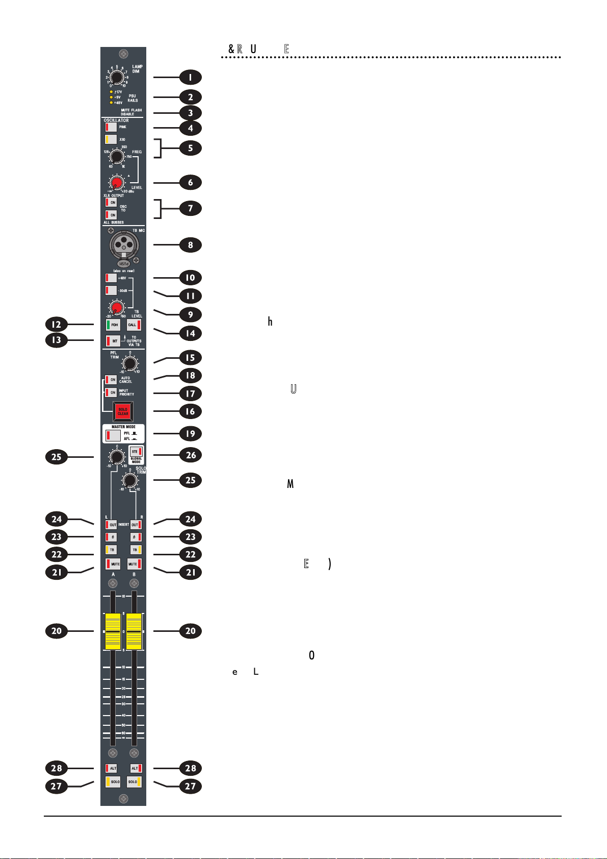
FIVE Monitor Functional Description 4.16
LL && RR OOUUTTPPUUTT SSEECCTTIIOONN
The lower half of the Master module comprises the Left/Right Output, which may
be used as two individual outputs or linked as a stereo pair.
p
FFAADDEERR
The 100mm fader controls the final level to the electronically balanced output.
a
MMUUTTEE
The output is muted when the switch is pressed, and the integral LED illuminates
to show that the MUTE is active.
s
TTBB
Pressing the latching TB switch arms the output to receive talkback from the cen-
tral talkback section, when the master TO OUTPUTS VIA TB INT switch is
active. The switch illuminates to warn that OSC is armed. The output is dimmed
by 6dB when talkback is active. Alternatively, if the Master Talkback signal is
already active, pressing TB routes the Talkback signal to the output, until the
switch is released. TB is injected post the meter takeoff point, so talkback signals
do not appear on the meterbridge.
d
ØØ ((PPhhaassee))
Pressing the Ø (Phase) switch reverses the phase of the output, to allow experi-
mentation for best feedback immunity with a multiple-mic setup. The switch is
illuminated when the phase is reversed.
f
IINNSSEERRTT ((OOUUTT))
The Insert Point consists of separate Send and Return jacks on the rear panel. The
Send is normalled to the Return.
The OUT switch bypasses the Insert Point when pressed, but leaves the pre-fade
output signal on the Send jack to feed external equipment if required. The switch
is illuminated when the insert is bypassed.
g
SSOOLLOO TTRRIIMM
SOLO TRIM gives +/- 10dB adjustment to the signal sent from that Output to the
AFL/PFL bus. This is useful for trimming a number of Outputs of varying levels to
give a consistent monitor level, thus reducing the requirement for manual Wedge
or ALT master adjustments whenever a SOLO is selected.
h
GGLLOOBBAALL MMOODDEE ((SSTTEE))
The GLOBAL MODE STE switch provides switching of the associated pairs of
send controls on the input channels between MONO and STEREO operation. In
STEREO mode, the SOLO switches on the L/R Outputs are linked in software, so
that pressing one automatically activates the other. See SOLO below for informa-
tion on how this switch affects the sends to the SOLO busses.
j
&&
k
SSOOLLOO // AALLTT
The SOLO switch feeds the pre and post-fade Group signal to one of two sets of
PFL and stereo AFL busses: Main or Alternate, depending on the setting of the
mechanically latching ALT switch k. The PFL / AFL state of the SOLO is affected
by the global PFL/AFL mode switch (see above). The PFL feed is post-INSERT.
Page 43

FIVE Monitor Functional Description 4.17
The function of the Output SOLO switch is also affected by the GLOBAL MODE
(STE) switch. If the mode is mono, each Output SOLO button switches an equal
feed at unity gain to each of the AFL left and right busses, and a PFL signal to the
PFL bus. If the mode is stereo, the SOLO switches are logic linked as a pair and
the AFL feed is changed to stereo, at unity gain. The PFL feed remains mono.
The SOLO switches can also remotely control a BSS Varicurve system - see
page 4.20 for details.
EEXXTTEERRNNAALL PPFFLL//AAFFLL
Additional PFL, AFL left and AFL right external inputs, from XLRs on the rearcon,
allow SOLO signals from another console to be added to the Main PFL and AFL
busses. The external PFL level is trimmed by the PFL TRIM pot (see above). When
no solos are active on the console, both PFL and AFL left and right external signals
are monitored by the Headphones and Wedge. The facility would be used when
linking another console as a slave to the FIVE Monitor.
Page 44

FIVE Monitor Functional Description 4.18
WWEEDDGGEE OOUUTTPPUUTT
l
WWEEDDGGEE FFAADDEERR
A stereo 100mm fader is provided for engineers Wedge speakers, and this nor-
mally receives the EXT SOLO signal (i.e. no signal, unless another slave console is
connected.) Whenever an input or output SOLO button is pressed, the Wedge
output switches to the corresponding internal or external PFL or AFL signal. An
internal jumper allows the output to be configured to receive the Left/Right output
instead of EXT SOLO, unless an internal SOLO is active. The Fader also controls
the overall level of the ALT WEDGE outputs if these are configured to follow the
Main Wedge (see SRC below).
;
MMAAIINN WWEEDDGGEE OONN
The Main Wedge is enabled when the switch is pressed. Note that the ALT
WEDGE output is unaffected, even if configured to follow the Main Wedge (see
SRC below).
z
MMOONNOO SSOOUURRCCEE LL//RR
MONO SOURCE buttons L and R allow either the Left or Right output/solo sig-
nals to be fed in mono to both Left and Right Wedge outputs without a gain
change, or if both are pressed, the output will be a mono sum of Left and Right.
This MONO SOURCE function is useful when handling stereo AFL signals on a sin-
gle monitor wedge.
x
WWEEDDGGEE IINNSSEERRTT ((IINN))
The Wedge Insert Point is normally bypassed, unless the IN switch is pressed, and
is before the Mono Source switching and the feed to the ALT WEDGE, so that
both Wedge outputs are affected by any devices inserted into the signal path. ALT
SOLO is not affected by the Insert.
c
AALLTT WWEEDDGGEE LLEEVVEELL
An Alternate Wedge stereo output is provided, with its own level control. The
feed to this output may either follow the Main Wedge or ALT SOLO, depending
on the position of the SRC (Source) switch (see below). The ALT WEDGE dims
with the Main Wedge.
v
OONN
Pressing the internally illuminated ON switch enables the Alt Wedge output, inde-
pendently of the Main Wedge.
b
SSRRCC ((SSoouurrccee))
When this switch is released, the Alt Wedge follows the Main Wedge, including the
Mono Source switching, Wedge Insert and Wedge Fader (subject to the PRE
switch, see below), but before the Main Wedge ON switch. When the SRC
switch is pressed the Alt Wedge listens to ALT SOLO.
n
PPRREE
The feed from the Main Wedge to Alt Wedge is normally sourced post the main
wedge fader, but may be switched to pre-fade by pressing the PRE switch.
m
PPHHOONNEESS
The engineers phones (and Wedge Meter in the overbridge) are fed by the post-
insert Wedge, pre Mono Source Wedge signal, but have a separate phones volume
control. The headphone socket is recessed into the front of the fascia (and dupli-
cated on the Master rear panel), and is driven by a high-power (1W into 8ohms)
headphone amp.
Page 45
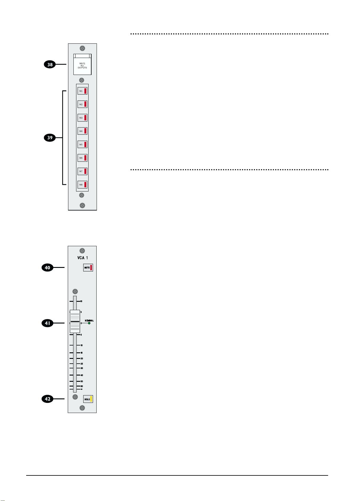
FIVE Monitor Functional Description 4.19
MUTE MMASTERS
,
MUTE AALL OOUTPUTS
The MUTE ALL OUTPUTS switch will MUTE every Group and Matrix Output on
the console (useful as either a ‘panic’ or ‘desk unattended’ switch). This switch is
covered to prevent accidental triggering.
.
MUTE MMASTERS
8 recessed latching buttons control the mute status of any channels assigned to the
appropriate mute group.
Inputs may be assigned to any combination of the eight master mute busses.
When an input channel is assigned to a mute bus, it is muted when the corresponding MUTE MASTER is pressed. The MUTE MASTER illuminates and the
input channel MUTE switch also illuminates to indicate that a non-local mute is
active.
VCA MMASTER FFADERS
These modules offer master controls for the 8 VCA Groups.
/
MUTE
Activating the MUTE on a VCA master will activate the MUTE on any slave input
channel, allowing groups of inputs to be MUTEd together with a single button
press.
[
MUTE MMASTERS
The attenuation or gain applied on a VCA Master Fader will be applied to all input
faders assigned as slaves to that VCA. The VCA Master Fader has 10dB of gain in
hand at the top of the fader.
The adjacent NOMINAL LED illuminates when the VCA Master Fader is at unity
gain. This is useful as an aid in setting ‘flat’ VCA Masters when the console is configured as a logic-linked slave to another ‘Master’ FIVE Monitor console.
]
SOLO
Activating a SOLO on a VCA Master will activate the SOLO on any slave input
channel, allowing groups of inputs to be PFL / AFL’ed together with a single button press.
Page 46
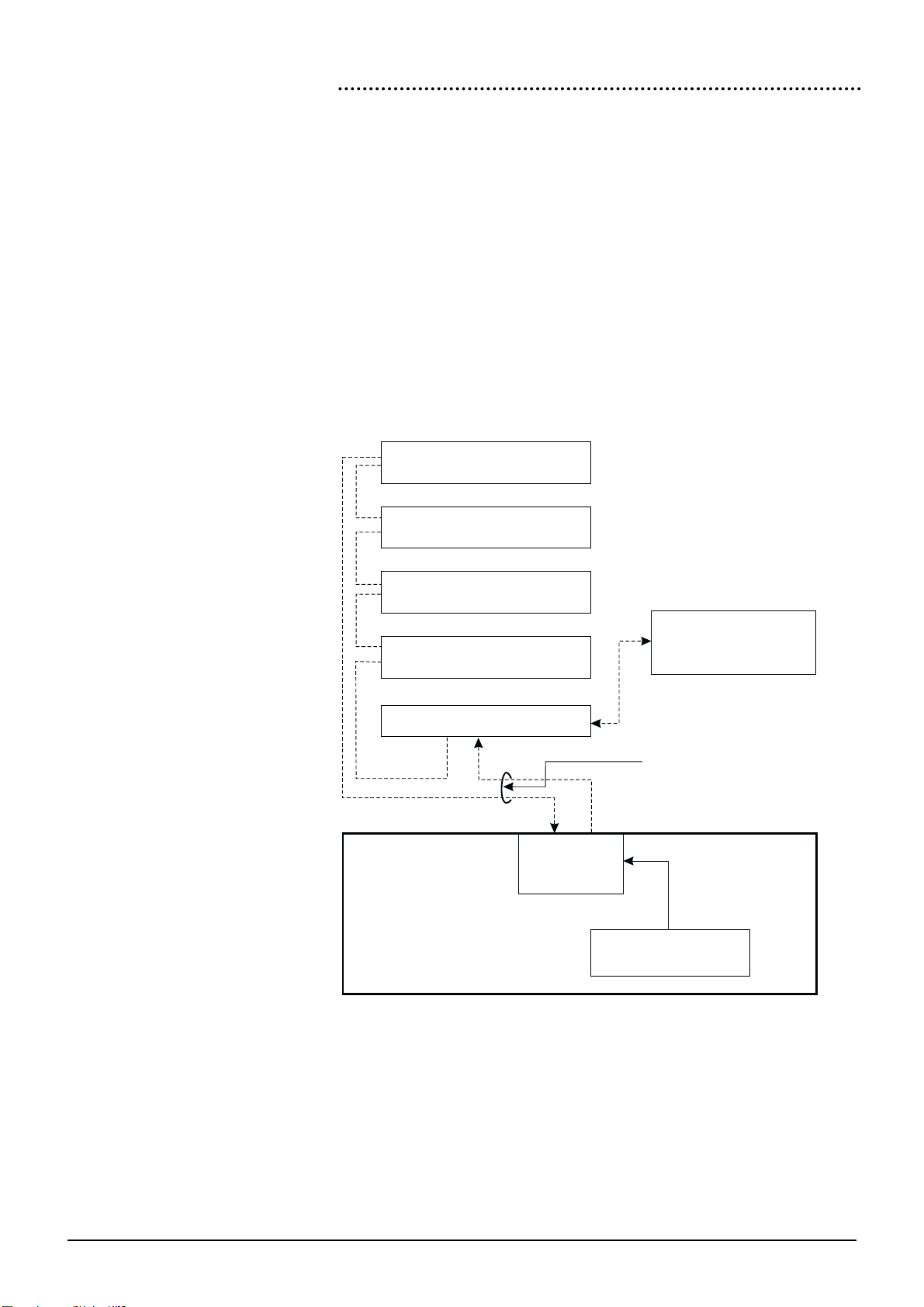
4.20 FIVE Monitor Functional Description
BSS VVARICURVE™ RREMOTE CONTROL
FIVE Monitor may be inserted into the MIDI loop of a BSS FPC-900 Varicurve™
Remote Control and Slave system (see diagram below.)
When so connected, pressing a SOLO on an Output of the FIVE Monitor will cause
the necessary MIDI command to be sent to the Remote unit to SELECT the EQ
associated with that Output, thus automatically bringing the EQ for the SOLO’ed
channel onto the remote for editing.
This feature saves time when setting up and editing the EQ parameters for a
Monitor rig, as the engineer no longer has to manually scroll through the various
slave units to find the appropriate device to edit - a press of the SOLO on the
FIVE Monitor will suffice.
Note that this function requires the Varicurve™ remote to be fitted with operating
system EPROM V1.16 or above; contact BSS for further information.
Varicurve Slave 1
Varicurve Slave 2
Varicurve Remote
FPC-900
(software V1.6 or above)
Varicurve Slave 3
Varicurve Slave 4
Varicurve Interface
FIVE Monitor Console
MIDI merge
processor
MIDI loop
Logic Trigger from
output SOLO buttons
Console is inserted
into the MIDI loop here
Page 47

FIVE Monitor Functional Description 4.21
LOGIC IIN // LLOGIC OOUT
Rear Panel EDAC connectors are provided to link the logic systems of one FIVE
Monitor with a second console in a Master/Slave configuration. See Chapter 2,
Installation, for connection details.
Rearcon PPanel
The connections on the Master rear connector panel are as follows:
All AAudio XXLRs
Pin 1 Gnd (Screen)
Pin 2 Hot (In-phase signal)
Pin 3 Cold(Out-of-phase signal)
3-ppole ‘‘A’ ggauge JJack - IInputs/Outpus ((inc. IInserts)
Tip Hot (In-phase signal
Ring Cold(Out-of-phase signal)
Sleeve Gnd (Screen)
3-ppole ‘‘A’ ggauge JJack ((Headphones)
Tip Left Signal
Ring Right Signal
Sleeve Gnd (Screen)
4-ppin XXLR ((Lamp CConnection)
Pin 1 & 3 +/-12V max. current 400mA
Pin 4 0v
Page 48

4.22 FIVE Monitor Functional Description
Page 49

FIVE Monitor Specifications 5.1
FFIIVVEE MMoonniittoorr
SSppeecciiffiiccaattiioonnss
5
Page 50

5.2 FIVE Monitor Specifications
TTyyppiiccaall SSppeecciiffiiccaattiioonnss
FFrreeqquueennccyy RReessppoonnssee
Any Input to any output . . . . . . . . . . . . . . . .20Hz - 20kHz, +0/-0.5dB
TToottaall HHaarrmmoonniicc DDiissttoorrttiioonn
All measurements at 20dBu
Line In to Direct Out (VCA out) . . . . . . . . . . . . . . . .Less than 0.006% @1kHz
Line In to Direct Out (VCA In) . . . . . . . . . . . . . . . .Less than 0.02% @1kHz
Line In to Mix Out (VCA out) . . . . . . . . . . . . . . . .Less than 0.008% @1kHz
NNooiissee
22Hz - 22kHz bandwidth, unweighted
Mic input Equivalent Input Noise . . . . . . . . . . . . . . . .Less than -127dBu (150Ω source)
Group Output Noise . . . . . . . . . . . . . . . .Less than -80dBu (32 ch routed)
Mix Output Noise . . . . . . . . . . . . . . . .Less than -80dBu (32 ch routed)
Group Output Noise (residual) . . . . . . . . . . . . . . . .Less than -92dBu
CCrroossssttaallkk
All measurements at 1kHz
Input Channel Muting . . . . . . . . . . . . . . . .Greater than 90dB
Input Channel Fader Isolation . . . . . . . . . . . . . . . .Greater than 90dB
Input Send Pot Routing Isolation . . . . . . . . . . . . . . . .Greater than 90dB
Group to Group Crosstalk . . . . . . . . . . . . . . . .Less than -90dB
Group to Mix Crosstalk . . . . . . . . . . . . . . . .Less than -90dB
IInnppuutt aanndd OOuuttppuutt IImmppeeddaanncceess
Mono Input . . . . . . . . . . . . . . . .1.6kΩ balanced
All Insert Sends . . . . . . . . . . . . . . . .Less than 75Ωbalanced
All Insert Returns . . . . . . . . . . . . . . . .Greater than 10kΩbalanced
Outputs . . . . . . . . . . . . . . . .Less than 75Ω balanced
IInnppuutt//OOuuttppuutt CCaappaabbiilliittyy
Maximum Input Level . . . . . . . . . . . . . . . .+30dBu
All Insert Sends . . . . . . . . . . . . . . . .+26dBu into 1kΩ
All Insert Returns . . . . . . . . . . . . . . . .+26dBu
All Balanced Outputs . . . . . . . . . . . . . . . .+26dBu into 1kΩ
Headphone Output . . . . . . . . . . . . . . . .+20dBu into 1kΩ
. . . . . . . . . . . . . . . .8W into 8Ω
IInnppuutt aanndd OOuuttppuutt LLeevveellss
Mono Input Sensitivity (XLR) . . . . . . . . . . . . . . . .-2dBu to -70dBu, +10dBu to -20dBu
All Insert Send/Return . . . . . . . . . . . . . . . .+4dBu nominal
Outputs . . . . . . . . . . . . . . . .+4dBu for 0VU
WWeeiigghhttss
24-bus, 44ch / 32-bus, 40ch . . . . . . . . . . . . . . . .156kg (343lbs)
24-bus, 52ch / 32-bus, 48ch . . . . . . . . . . . . . . . .170kg (374lbs)
24-bus, 60ch / 32-bus, 56ch . . . . . . . . . . . . . . . .185kg (407lbs)
 Loading...