

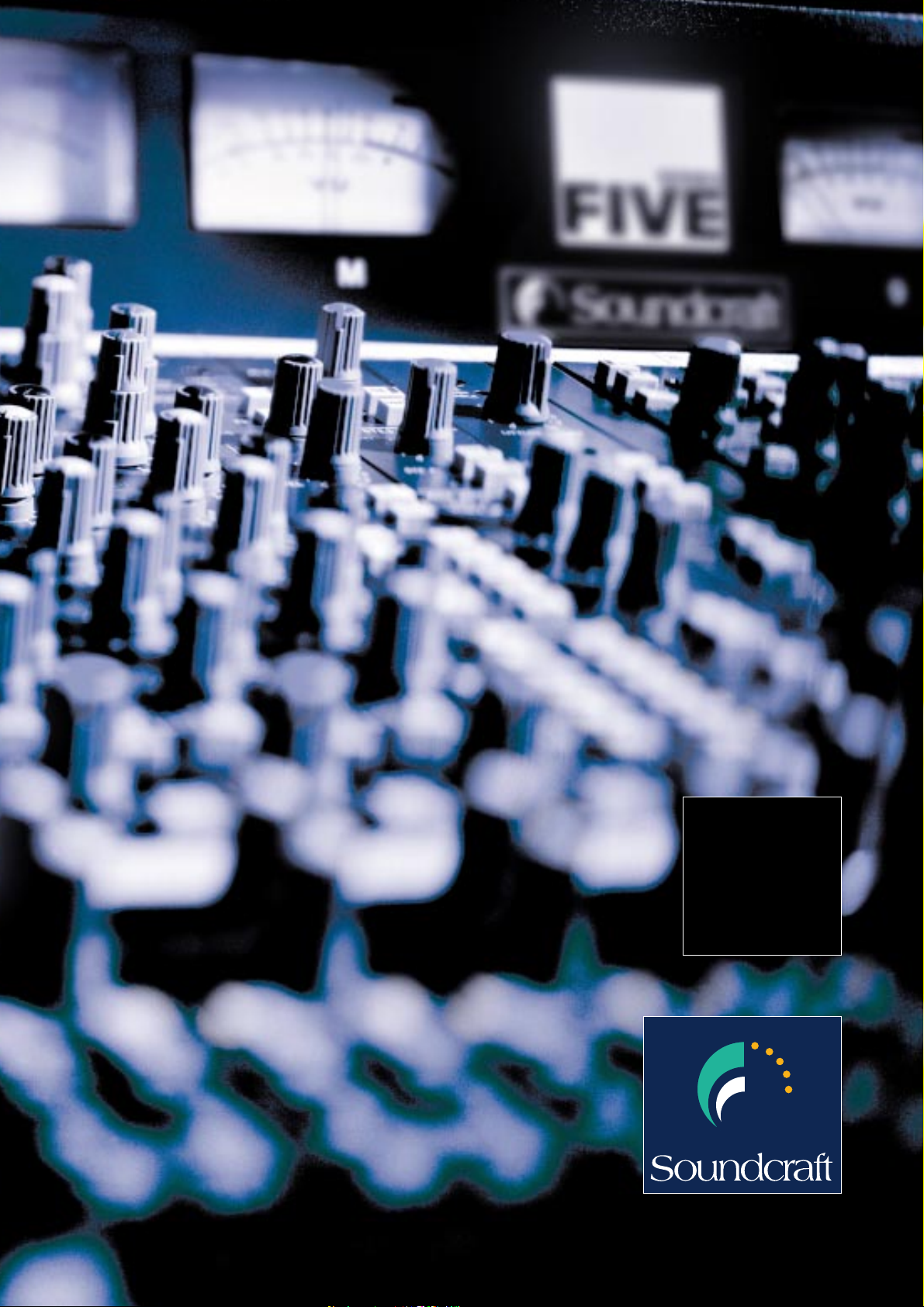
SERIES
FIVE
Solution Without Compromise


• 24-56 channel frame sizes
• 4 stereo mic / line inputs
with full EQ as standard
• Rugged power supply with
three year warranty
• 8 sub-groups
• 12 auxiliary busses
• 10 VCA groups
• Built-in 16x10 output
matrix
• 4-band fully parametric EQ
on both mono and stereo
inputs
• Sweepable filters on all
input channels
• Input metering on every
channel
• VU output meterbridge
included as standard
• 8 mute groups plus 256
MIDI controllable
snapshots of all input and
output mutes
• MIDI program change
transmission and
DataFader continuous
controller
• Switchable LCR panning as
standard
• Compact, lightweight
frame designed to
withstand touring
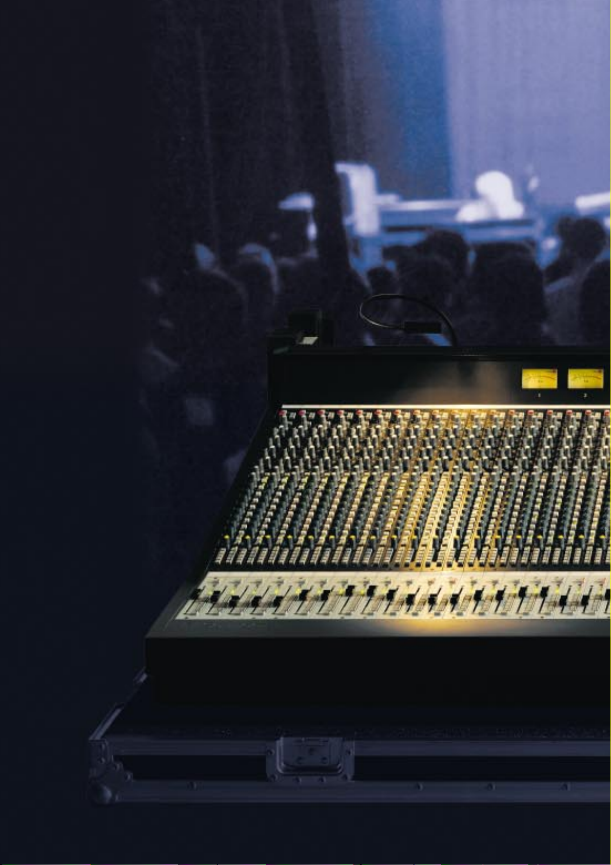
Soundcraft -
Innovation In Live Sound
ver 20 years of success in
mixing console design and
O
Soundcraft unique insight into the
demands of leading audio
professionals. Through the
application of this experience, and
having sought the opinions of top
live sound engineers and designers,
Soundcraft has arrived at what it
strongly believes to be its best front
of house console yet. Soundcraft set
out to provide a great-sounding,
fully-featured and affordable live
sound console. This is now complete,
and is called Series FIVE.
manufacture has given
Available in frame sizes of 24 to 56
input channels, Series FIVE is ideally
suited to a whole range of demanding
applications from touring to theatre
installation. Series FIVE’s
comprehensive standard feature set
includes LCR panning, aux master
levels on 100mm faders, full-spec
stereo modules and FX returns, plus
flexible MIDI scene control. Despite
the Series FIVE's high level of
facilities, the console's layout is clear
and reassuringly familiar. This has
been achieved without compromising
the audio quality.
A Proven History
oundcraft has always been well respected
for its audio performance and British
S
sound, and this was never so true as
with the Series Four and Europa consoles.
Building on this success and combining
it with the feature set and flexibility
demanded by today's engineers, Soundcraft has created
Series FIVE - the natural progression.
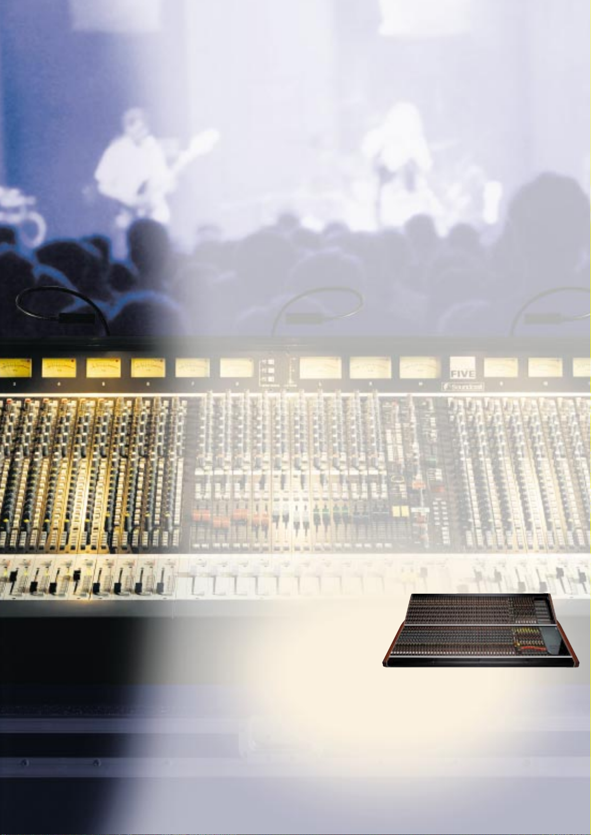
Designed For Professionals
WIDE RANGE OF
FRAME SIZES
Five frame sizes are offered as standard 24, 32, 40, 48 and 56 mono channels.
Mono channels can be replaced by stereo
modules, in blocks of two or four,
together with the appropriate rear
connectors.
4 STEREO INPUTS INCLUDED
AS STANDARD
Each frame size has an
additional four stereo
modules included as standard.
These stereo mic / line
channels are fully featured
and include a four band fully-parametric
EQ as per the mono input.
balance rather than individual levels. Aux
12 can be switched away from its bus to
provide a channel direct output. These
auxiliary outputs are routable to left /
right / mono (centre) thus enabling them
to be used as additional sub groups.
10 VCA GROUPS
A bank of 10 VCA
groups is controlled
by 100mm faders
located below the
output section.
These determine the
overall level and
mute status of any
input channel
assigned to them.
12 AUXILIARY
BUSSES
All of the 12
auxiliary sends are
independently on /
off and pre / post
switchable when
the first four are
globally set to act
as two stereo sends.
In this set-up the
dual concentric pot
controls level and
8 SUB-GROUPS
8 mono sub-groups are
provided, each with an
insert send and return on
separate balanced jacks,
plus routing via the pan
pot to left / right / mono
(centre).
SWEEPABLE FILTERS
Both the mono and stereo
input channels include a
sweepable high-pass filter
while the mono module
offers the additional
flexibility of a sweepable low-pass filter.

BUILT-IN 16x10 MATRIX
In addition to the 8 sub-groups and 12
aux busses, Series FIVE offers a 16x10
output matrix. Each of the 10 outputs
can be derived from the 8 sub-groups,
left, right and mono (centre) outputs, aux
busses 1-4 and an external stereo line
input. Individual talkback and mute are
provided, as well as external mute which
is part of the console's snapshot
automation system.
INPUT METERING ON EVERY CHANNEL
Signal level metering is built-in to every
input channel. The mono module
has a 10-segment LED bargraph
situated adjacent to the fader
for maximum visibility while the
stereo channel uses five
segments for each side of the
stereo signal.
OUTPUT METERBRIDGE INCLUDED
AS STANDARD
The Series FIVE
meterbridge is fitted
with 3 large VUs
which read the master
left, right and mono
(centre) outputs, and
12 smaller VUs which
are switchable
between sub-groups
1-8, aux sends 1-12,
and matrix outputs 110 via the meter source switch bank. An
LED phasemeter displays phase
correlation between the left and
right signals.
SWITCHABLE LCR PANNING
When activated via the switch on each
mono channel, the LCR panning mode
selects the mono bus as a dedicated
centre output. The pan control then pans
from left to centre, and centre to right.
When the pan pot is at
its centre detent, audio
output is removed from
the left and right busses.
MUTE CONTROL / MIDI MUTE
AUTOMATION
The Series FIVE MIDI module provides a
comprehensive array of functions. 8 mute
groups can be created, along with up to
256 snapshots of the console’s mute
switch status. Each
snapshot incorporates a
MIDI Program Change
message for automating
setting changes in external
effects units, plus a
continuous controller
number for the DataFader,
delivering realtime control of
external effects
parameters.
Note On
messages can
also be
transmitted to trigger
samplers and other
external units.

Creative Power
ne of the most critical components in any console is its
power supply and, with the CPS 2000 PSU, our
O
which sets new standards in performance and reliability. The use
of high-quality components and fewer voltage rails makes for a
simple, reliable system, and the CPS 2000 delivers ample
headroom: a 48-channel Series FIVE enjoys 30% spare
headroom capacity. A digital display on the front of the unit
fail-safe operation, without the need for a switcher box, whilst
heavy-duty Socapex® DC connectors link the PSU output to the
console. The CPS 2000 is cooled by quiet yet hard wearing
PAPST® fans, fitted with filters for easy access. CPS 2000 carries
a three-year warranty.
designers and service engineers have created a device
provides precise continuous
monitoring of incoming voltage,
and with world-wide usage a prime
consideration, Series FIVE will
operate with inputs as low as 80
volts. Built-in diode linking allows
two PSUs to function in parallel for
• Linear circuitry uses industry standard components
• 30% spare headroom with standard 48-channel console
• Fewer voltage rails makes for a simpler, more reliable
configuration
• Load is spread across several power devices on each rail for
optimum heat dissipation
• Heavy current wiring is all hard soldered minimising
number of connectors

• Front panel digital mains voltage meter aids correct
voltage tap setting
• Built-in diode output linking allows two supplies to be
connected for redundancy
• Heavy duty Socapex® DC connectors link PSU to console
• High quality PAPST® fans for reduced noise
and longer product life
Built To Last But Designed To Be
Moved
One of the priorities at the design phase of Series FIVE
was to concentrate on creating a console which strikes
the right balance between ruggedness and portability.
The result is that a fully-specified 48-channel Series
FIVE weighs just 180 kg/396 lbs, is under 227cm/90
inches wide and measures just 92cm/36 inches from
front to back. It is a four-person lift, and smaller
configurations can
be lifted by just two
crew. But its
lightweight
construction does
not mean that
Series FIVE has
seen any
compromise in its
build quality. Its rugged
sub frame has been designed to
withstand the most demanding working
environments. Series FIVE's compact size and
comprehensive features, combined with its affordability,
make it the perfect choice for tour sound companies,
large installations, stadiums, and theatres alike. Series
FIVE provides the solution without compromise.
• 4U high 19” rackmountable
Rugged sub-frame construction

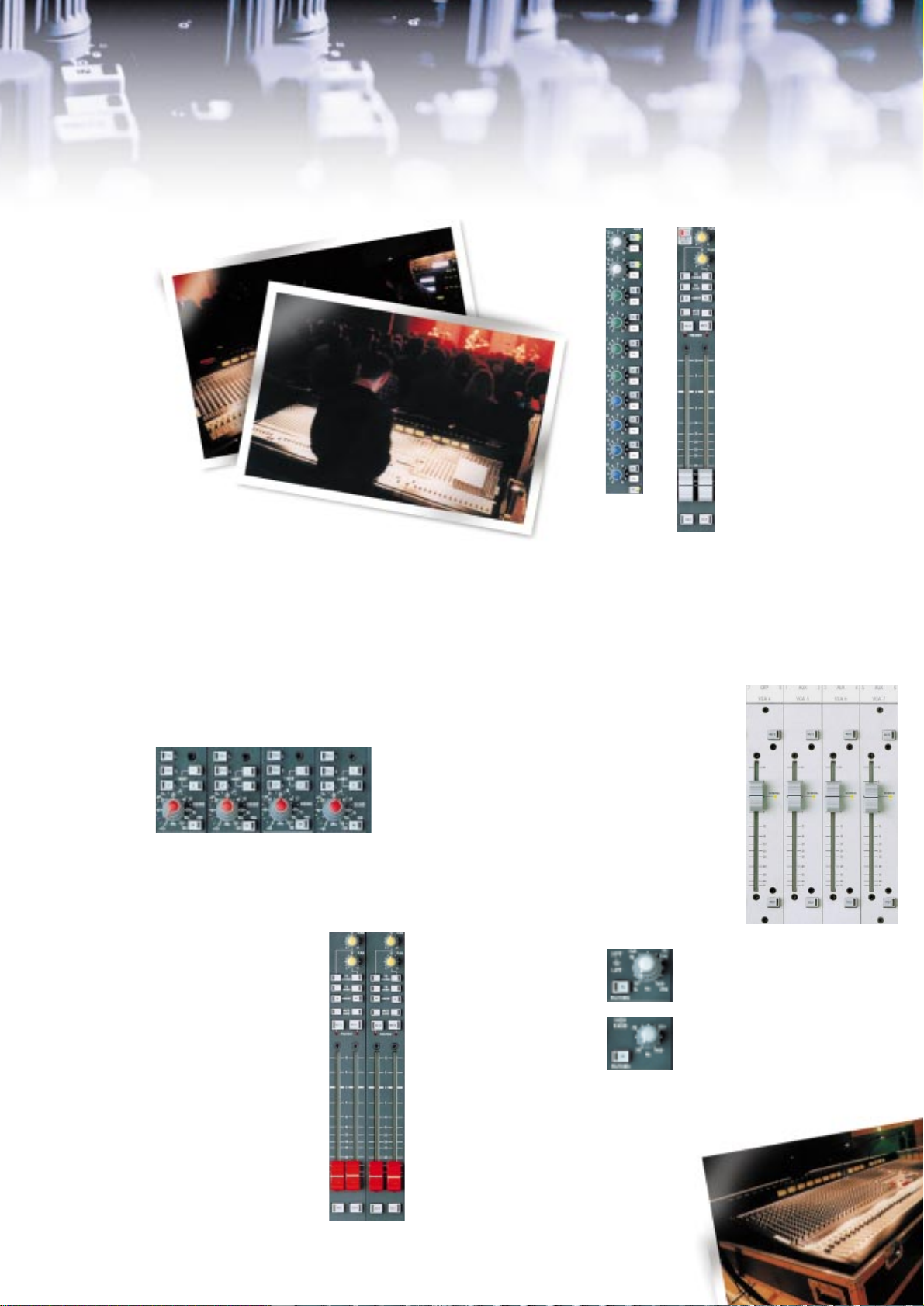
Series FIVE Input Modules
Mono
input module
ur research told us that live
sound engineers want to see
O
possible to the mono, in terms of the
features they offer. This is exactly what
Series FIVE delivers. Many other consoles
reduce the specification of their stereo
modules, but with Series FIVE, the stereo
input processing is almost as
comprehensive as the excellent mono
module. Stereo modules function equally
well as input channels or as FX returns;
and four are included as standard with
every Series FIVE console in addition to
the mono channels specified by the
configuration.
INPUT STAGE
The mono module accepts two balanced
inputs via XLRs at microphone or line level.
The B switch selects the required signal, and
individual +48V switches apply phantom
power to either input. This flexibility means
that a second console for the support band
often becomes superfluous, as the engineer
can use the B input for the support band
multicore, and switch across to input A for
the main act in seconds. The RNG button
switches the range of the input stage
between -2dBu to -70dBu and +10dBu to 20dBu, before the signal is routed through
the SENS (Sensitivity) pot which then
allows finer adjustment of input gain. This
feature, unique to Soundcraft consoles,
provides a much more efficient way to set
signal levels in the input stage than a
traditional PAD control. Amplifying a signal
after it has been reduced in level by a PAD
degrades the noise performance of the
amplifier, as there is unnecessary gain
present in the input stage. Also, the position
of the resistors in a PAD circuit degrades
the amplifier’s common mode rejection
(CMRR). In live applications which require
long microphone cables and multicores,
effective interference rejection is crucial.
Series FIVE’s input stage solves these
problems by using two separate active gain
stereo modules as similar as
stages which are switched in and out as
required via the RNG switch. The Phase (ø)
switch reverses the polarity of the selected
input. The balanced insert point can be
switched in circuit via the INS IN button.
The layout of the stereo module’s input
stage is as close as possible to that of the
mono channel. Individual RNG and +48V
buttons are provided for each side of the
stereo input, while the Phase switch
reverses the polarity of the left signal. The
RNG and SENS functions work in exactly
the same way as those on the mono
module, meaning that the stereo channels
will accept microphone levels, and are not
line specific as on some consoles. Given that
stereo modules can be specified instead of
mono channels in banks of two or four, a
40-channel frame with 16 stereo inputs
fitted will yield a massive 60 microphonecapable inputs in an extremely compact
size.
FILTERS
A smooth, accurate filter system is crucial
to live sound engineering. Both modules
boast a sweepable high-pass filter which
can be switched out of the chain when not
in use, and the mono channel has the
additional flexibility of a switchable lowpass filter.
EQ
Soundcraft consoles are renowned for their
smooth, musical EQ and Series FIVE is no
exception. The legendary four band, fully
parametric EQ seen on the Series Four and
Europa consoles has been further refined
for Series FIVE, and is fully implemented on
both mono and stereo modules. The one
slight difference is that to use the HF and
LF bands as shelving EQ, there are switches
on the stereo module, whereas on the
mono channel a click switch at the endstop of the Q pot invokes this function. On
both modules, the EQ can be switched
completely out of the signal chain when it
is not in use.

Stereo
input module
AUXILIARY SENDS
12 full-time auxiliary sends are provided,
which when combined with the 8 subgroups and 10 matrix outputs, make
ample provision for effects sends,
foldback mixes, additional feeds and
other output requirements. Sends 1-4 can
be globally switched in pairs (the button
is located on the output section) to act as
stereo sends, in which case the dual
concentric controls act as level and
balance, rather than as individual level
controls. On the stereo module, switches
on Aux 1-4, 5/6 and 7/8 allow the
engineer to select whether these sends
are derived from a summed mono signal,
or sourced as stereo from the left and
right sides of the stereo channel. On the
mono module, Aux 12 can be routed
away from its bus and to the direct
output via the DIR switch; this allows the
engineer to create a pre-fader direct
output, ideal when making a
simultaneous multitrack recording.
ROUTING AND PANNING
Individual routing switches send the post
fade signal to the 8 sub-groups (direct or
through the pan pot depending on the
setting of the PAN switch), the mono bus
(MNO), or the main left-right outputs
(MIX). The LCR button on the mono
module uses the mono bus to provide a
dedicated centre output. On the stereo
module, the pan pot is dual concentric,
providing full independent left-right
panning of each side of the stereo signal,
or easy control over the width of the
stereo image.
remotely controlled from the mute
master section, and the semi-recessed
Mute Safe switch protects the channel
from mute groups, VCA mutes, snapshots,
or Solo-in-place - the channel can still be
muted locally. The Preview LED allows
editing and checking of mute groups and
snapshots without disturbing the audio
passing through the channel. The 10
numbered switches assign the channel to
any combination of the 10 VCA groups,
which then assumes control of the level,
mute and solo buttons on that channel.
The Solo button provides either a mono
PFL or a stereo AFL, or Solo-in-place,
depending on the mode selected on the
master section.
INPUT MODULES BACK PANEL
CONNECTIONS
Mono Module
Inputs A and B are
connected via the
balanced XLR sockets.
The direct output is on
a balanced XLR, and the
insert sends and returns
are all on separate
balanced 1/4” jacks.
Stereo Module
The inputs are on two
balanced XLRs, and individual insert sends
and returns for each side
of the stereo signal are
provided on balanced 1/4”
jacks.
FADER AND MUTING
A high quality 100mm fader controls the
output level to all busses, and offers 10dB
of gain when fully raised. An expanded
scale is provided around unity for precise
control. The channel Mute switch can be

Series FIVE Output Section
Sub-group
output module
he output section of Series FIVE
revolves around the principle that
T
output controls for both auxiliary
masters and sub-group sends should be
identical, so that they are
interchangeable according to the
current task. Therefore if the 8 subgroups are not enough for a particular
job, some of the 12 auxiliary sends can
be used as additional groups. The
output section consists of 10 identical
dual modules - 4 of which control the 8
sub-groups, with the other 6 controlling
the 12 auxiliary sends. Each module
also controls one of the 10 matrix
outputs.
MATRIX OUTPUTS 1-10
A 16x10 output matrix is provided as
standard on the output section of every
Series FIVE console, and combines with
the sub-groups and aux sends to provide
an outstanding level of mixing versatility.
Each output can be derived from any
combination of sub-groups 1-8, aux
sends 1-4, the main left-right busses, the
mono output, and a dedicated external
stereo input. The left side of the external
input is normally fed to the oddnumbered matrices, and the right side to
the even, although jumper options allow
the signal to be summed. Contributions
from the 8 subgroups, left-right, mono +
aux 1/2 and 3/4 make up the matrix mix,
and are individually controllable via
rotary pots. A balanced insert is
switchable via the IN button, and the
latching TB button injects the talkback or
oscillator signal (as determined in the
master section) into the matrix output,
pre-fader. The rotary Matrix Master fader
has AFL or PFL solo (depending on
settings in the master section) as well as
a Mute switch which can be activated by
the 8 mute groups or the 256 snapshot
settings. A Mute Safe switch protects the
output from remote muting, while
retaining the capacity for local muting.
8 SUB-GROUP MASTER FADERS
Each sub-group has a high quality
100mm fader (coloured red) controlling
the level to the balanced output. A
balanced insert point is provided, which is
switchable via the IN switch. Mute and
Mute Safe buttons function in the same
way as those on the matrix outputs, and
the Solo buttons provide AFL or PFL
facilities depending on the settings in the
master section. The sub-groups can be
routed to the mono and / or left-right
busses via the To Mono and To Stereo
buttons; a pan pot is provided for
sweeping between the left-right busses.
12 AUXILIARY MASTER FADERS
Each auxiliary master is controlled by a
high quality 100mm fader (coloured to
match the send knobs on the inputs).
Features of the auxiliary master output
section are identical to those of the subgroup section, allowing any spare
auxiliaries to be used as sub-groups if
required.
Master / group upper
rear connector panel
Auxiliary
output module
VCA
control
faders
GLOBAL MONO / STEREO SWITCHING
Auxiliaries 1-4 can be used as four
individual mono sends, or they can be
ganged and used as two stereo sends. In
the first instance, the dual concentric
send controls on the input modules
control individual levels, and in the
second they control level and balance.
The first two auxiliary master modules
feature switches for setting this mode,
which can be set independently for Aux
1/2 and Aux 3/4. In addition, in stereo
mode, the Mute and Solo buttons on the
output modules are logic linked such that
the operation of one will automatically
trigger the other.
METERING
Every Series FIVE console features an
integral VU meterbridge. 3 large VUs are
dedicated to measuring the left, right and
mono (centre) outputs. A bank of 12
smaller VUs can be selected to read subgroups 1-8, aux sends 1-12 or matrix
outputs 1-10 via a meter source switch
bank. The left and right meters also
automatically switch to read any soloed
signal. A unique feature of Series FIVE is
the integral LED phasemeter, which
measures the phase correlation of any
signals which appear at the L and R VU
meters. This will normally be the left and
right outputs, but when in stereo AFL
mode, the phase of any soloed stereo
source can be checked.
MASTER / GROUP UPPER BACK PANEL
CONNECTIONS
The 8 sub-groups, 12 auxiliaries, left,
right and mono outputs are all on
balanced XLRs, with inserts on balanced
1/4” jacks (individual for send and
return). Other balanced XLR outputs are
for monitor output, PFL and stereo AFL. A
headphones socket is provided which
mirrors the one on the front panel of the
master section. A 4-pin XLR socket offers
400mA of power for the connection of
Littlites™ - the number of these outlets
varies according to console frame size.
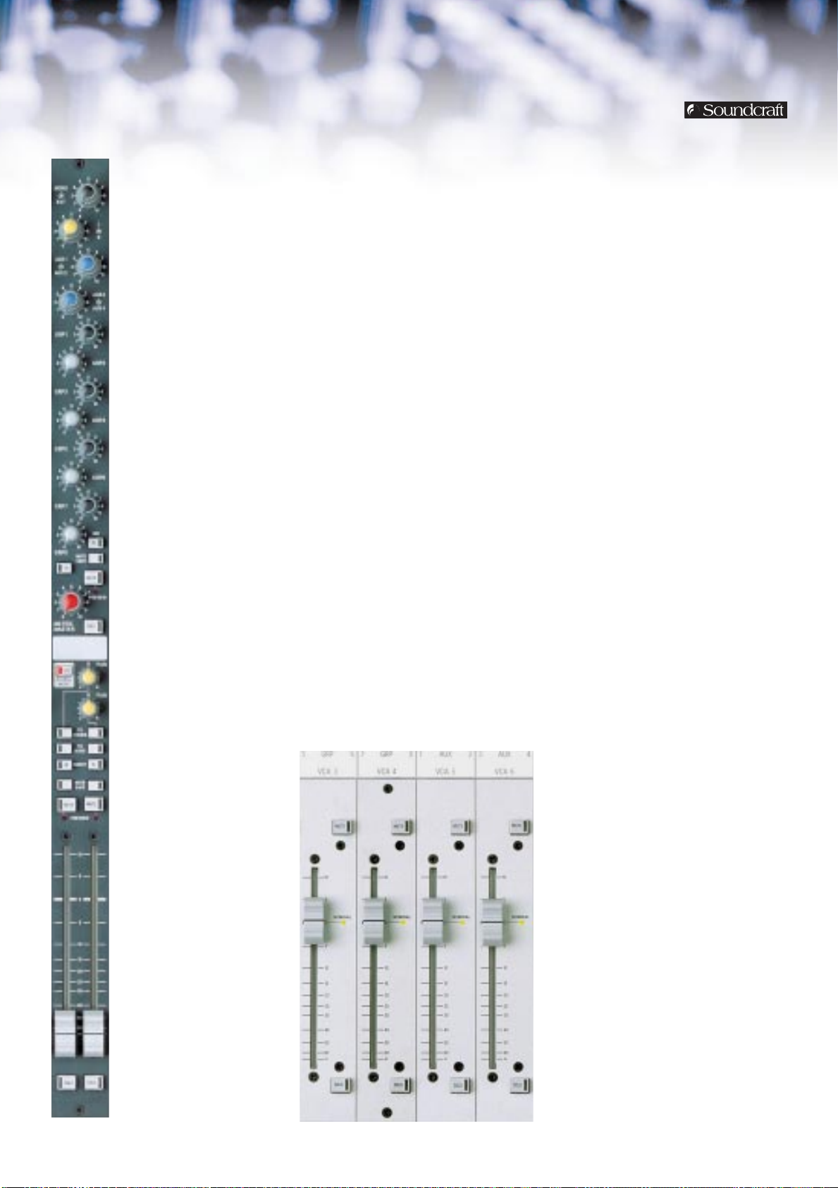
10 VCA GROUPS
A bank of 10 VCA master faders controls
the level of any mono or stereo channel
assigned to a VCA group. Mute and Solo
buttons are provided for each fader, and
act effectively as a remote control for
any channel assigned to that VCA group
(unless that channel has its Mute Safe
function engaged). Therefore any solo
mode (PFL, stereo AFL or Solo-in-place)
can be activated for an entire VCA group,
depending on the setting of the global
console solo mode. The Nominal LED on
each fader allows fast and accurate
return to unity gain.

Series FIVE Master Section
Master 1
module
he Series FIVE master section is
two modules wide and contains
T
the main left, right and mono
faders, as well as monitoring controls,
talkback, and an array of controls which
further enhance the flexibility of
Series FIVE.
PSU RAILS
Voltage indicators for the +/-17V, +5V
and +48V rails on the PSU are provided
and offer constant visual confirmation
that the power supply is providing an
accurate voltage.
TALKBACK AND OSCILLATOR
The built-in oscillator can generate pink
noise or a sine wave in a frequency range
of 63Hz to 10kHz. The PINK button
toggles between pink noise and sine
wave, and the x10 button increases the
range of the oscillator frequency control
from 63Hz-1kHz to 630Hz-10kHz. An
oscillator level pot is also provided. The
oscillator can be routed to its dedicated
output (on balanced XLR) or to a
combination of sub-groups, aux busses,
left, right and mono outputs. The busses
which receive the oscillator signal are
determined by a bank of illuminated
switches, which also nominates the
busses which will receive the talkback
signal when the INT button is depressed.
This facility is also provided on the matrix
outputs, by using the TB switch on each
matrix master. Talkback can also be
routed to its Soundcraft proprietary
intercom output (compatible with SM
monitor consoles or another Series FIVE)
via the EXT button. An external talkback
input is provided for accepting such a
link with another Series FIVE. A front
panel talkback mic input socket (XLR) is
provided, together with a level control, a
-30dB pad switch and a +48V phantom
power button, and for convenience this
socket is mirrored on the back panel.
ALTERNATE STEREO OUTPUTS
In addition to the main left-right stereo
mix outputs, three alternate stereo
outputs are provided, which allow the
creation of feeds for broadcast or
recording which would otherwise tie up
several matrix outputs. ALT STE1 is
controlled by two 100mm faders, and the
levels of ALT STE2 and ALT STE3 are on
rotary faders. All are switchable to be pre
or post the main left-right faders, and all
have a MNO button which sums the two
sides of the stereo signal, thereby
offering a mono feed.
AUX RETURNS
Two auxiliary returns are provided, with
sensitivity switchable between -10dBV
and +4dBu, and with the signal routed
directly into the left-right mix bus. 2band shelving EQ at 60Hz and 12kHz is
provided, and the input level is controlled
by a rotary fader. Mute and Mute Safe
are provided, and the Solo button will
allow mono PFL or stereo AFL monitoring,
depending on the setting of the console’s
global solo mode.
Master / group lower
rear connector panel

Master 2
module
SOLO CONTROLS
Every aspect of Series FIVE’s design has
been carefully thought out, and the solo
system is certainly no exception. It has
been carefully developed in conjunction
with mixing professionals, to ensure that
this crucial aspect of the console’s design
is flawlessly implemented. The Master
Mode button dictates whether the
selection of a Solo function should result
in mono PFL or stereo AFL monitoring,
unless the large protected Solo-in-place
button is lit. In this instance the
destructive in-place stereo solo will be
engaged, allowing the engineer to listen
to a channel in its proper place in the
stereo field, plus any associated effects.
Rotary pots are provided to trim the level
of the AFL and PFL busses. The Auto
Cancel facility means that any Solo
button selected will cancel the previous
solo. When not in this mode, the selected
Solos become additive. With the Input
Priority button on, soloing an input
channel will temporarily override any
output solo which may be present. When
the input solo setting is released, the
original output solo will again become
active. A large illuminated Solo Clear
button allows fast, one touch cancelling
of all solo settings throughout the entire
console control surface.
MONITOR CONTROLS
Separate rotary fader controls are
provided for headphone level and
monitoring level. The two outputs follow
the same source; this is selected between
the mono bus and the main left-right mix
outputs. The stereo signal can be summed
if required via the SUM L+R button. The
selected monitor source will be overridden
by any input or output solo operation.
MASTER FADERS
Levels for the mono and left-right mix
outputs are controlled by 100mm long
throw faders. The stereo faders are yellow
and the mono fader is black. Mute and
Mute Safe switches are provided for each.
The mutes can be controlled by the
snapshot system.
MASTER / GROUP LOWER BACK PANEL
CONNECTIONS
The outputs for the 10 matrix sends are
on balanced XLRs, and each has an insert
with send and return on separate
balanced 1/4” jacks. The two stereo aux
returns are on balanced XLRs, as are the
three alternate stereo outputs. Standard
MIDI in, out and thru ports are provided.
An oscillator output, external talkback
output, external talkback input and
talkback mic input are all connected via
balanced XLRs.
LINK BACK PANEL CONNECTIONS
Sub-groups 1-8, auxiliaries 1-12, PFL, AFL,
mono and left-right mix busses are all
available for audio linking in situations
where two Series FIVE consoles are being
linked. Inputs flow straight into the busses
at unity gain, and all bus inputs are
accessed via balanced XLRs. 38-way EDAC
logic in and out connectors allow full logic
linking of VCAs and solo controls between
two Series FIVE consoles.
Link rear connector panel

Mute Control / MIDI Module
MIDI / mute
module
MUTE CONTROL / MIDI MODULE
Series FIVE’s mute control and MIDI section
allows the creation of 8 mute groups and
up to 256 snapshots of the console’s mute
switch status, as well as the transmission
and reception of MIDI program change and
note ON/OFF messages, allowing the
console to exercise real-time control over
any suitably specified MIDI device.
PREFERENCE SETTINGS
Under normal circumstances, when a Soloin-place or a VCA mute is activated, all
affected channel mute buttons will flash to
indicate that they are being muted by
remote control. This flashing effect can be
disabled if desired using the recessed
button. A rotary pot controls the brightness
of the Littlites™ connected to the power
outlet ports on the rear panel. In the
unlikely event of system failure, the backup
contingency of a Processor Reset button
allows complete disabling of the mute
control processor, allowing all console
mutes to operate manually.
BULK DUMP BUTTONS
The memory contents of Series FIVE can be
saved to and reloaded from an external
MIDI device such as a sequencer or data
filer. This means that snapshot set-ups can
be archived and recalled at a moment’s
notice.
DATAFADER
The DataFader that proved so successful on
previous Soundcraft consoles has been even
further improved and comprehensively
implemented on Series FIVE. The fader
sends out continuous controller data to the
MIDI OUT socket whenever it is moved on
its currently assigned MIDI channel. The ON
button allows the fader to be disabled, or to
be punched in at a set value. The fader
position is storable in a snapshot, for
automation reset.
MUTE ACTIVE AND PREVIEW
In active mode, any snapshot or mute
group which is recalled will instantly
override any mutes which are currently set.
In Preview mode, recalling a snapshot or
mute group will not change any settings,
but will make the preview LEDs beside the
relevant Mute buttons flash. This allows the
engineer to check a mute group or
snapshot during a show without affecting
the audio. Snapshots and mute groups can
also be edited and stored in this mode,
again with no audible effect.
NUMERICAL KEYPAD
The 0-9 numerical keypad and its adjacent
up / down buttons allow direct or
incremental keying of snapshot or program
change numbers into the digital display.
MUTE MASTER BUTTONS
The large illuminated mute master buttons
allow fast store and recall of the 8 mute
groups. More than one mute group can be
active at once, thereby layering the groups.
This section also houses the angled recessed
headphones socket.
Series FIVE Jumper Options
Module Function Options Default
Mono Channel insert Pre or post EQ Pre EQ
Mono I/P channel meter source Pre or post fade Pre fade
Mono Aux 1-4 PRE source Pre or post EQ (always pre fader) Post EQ
Mono Aux 5-8 PRE source Pre or post EQ (always pre fader) Post EQ
Mono Aux 9-11 PRE source Pre or post EQ (always pre fader) Post EQ
Mono Aux 12 PRE source / DIR Pre or post EQ (always pre fader) Post EQ
Mono Pre EQ feed Pre or post mute Post mute
Stereo Channel insert Pre or post EQ Pre EQ
Stereo I/P channel meter source Pre or post fade Pre fade
Stereo Aux 1-12 PRE source Pre or post EQ Post EQ
Stereo Aux 9, 10 source Mono or stereo Mono
Stereo Aux 11, 12 source Mono or stereo Mono
Stereo Pre EQ feed Pre or post mute Post mute
Output Matrix ext I/P sensitivity -10dBV or +4dBu +4dBu
Output Matrix ext I/P source Ext I/P left, right or mono Left to odd, right to even

Series FIVE MIDI Applications
The mixing engineer today is required to deal
not only with the audio mixer itself, but also
with a bank of external programmable effects
units, samplers and other replay devices. Series
FIVE integrates a high level of MIDI control into
the front panel of the console, which allows the
engineer to automate much of the outboard
equipment switching and parameter changing.
Series FIVE MIDI For System Setup
Many outboard processing devices have
memories or patch locations into which the user
can store settings for different sections of the
show. Recalling these settings manually from the
front panel of the unit entails leaving the
mixing surface, thereby distracting the attention
of the engineer. Series FIVE can send a user-
Program 1
SERIES FIVE
sent with
scene
MIDI
OUT
Program 1
MULTI FX
IN
THRU
recalled
MIDI
IN
IN
Program 1
recalled
Program 1
recalled
DELAYS
THRU
EQ
Fig 1. Configuring the system with Series FIVE MIDI.
programmable MIDI program change message
for each snapshot to the MIDI OUT port at the
rear of the console. This can be connected to the
MIDI IN on any suitably-equipped device, which
will then receive that Program change. This is
interpreted by the effects unit and is equivalent
to recalling a new memory location from the
front panel of the device itself. For example,
Program Change no 1 sent on MIDI Channel 1
will change the device receiving on MIDI
Channel 1 to the first memory location, Program
Change no 2 will select the second, and so on.
Although Series FIVE generates just one Program
Change per snapshot, if all remote devices are
set up to receive on the same MIDI channel,
then they will ALL follow the Program Changes
sent from Series FIVE, as shown in figure 1. In
this example, the MIDI OUT of the console is
connected to a multi-effects unit, a delay
device, and a programmable EQ. All units have
the correct settings for the beginning of the
event stored in memory location 1. Series FIVE
sends Program Change no 1 on MIDI Channel 1
to the first effects device. This Program Change
is then passed THRU to the remaining devices.
Whatever the status of these devices, they are
instantly reset to Memory location 1, ready for
the start of the show, without the user having to
touch any of the units.
Series FIVE MIDI For Sample Triggering
MIDI will also handle NOTE ON and NOTE OFF
messages, which are equivalent to playing notes
on a sampler keyboard, with 128 note values
covering the keyboard range. These message
SAMPLER
AUDIO SENT
3 2
TO CONSOLE
SERIES FIVE
SAMPLE ON NOTE ‘O’ IS
TRIGGERED IN SAMPLER
MIDI NOTE ‘O’
SENT WHEN
CHANNEL
UNMUTED
1
MIDI
AUDIO
Fig 2. Triggering samples with Series FIVE MIDI.
types are particularly useful in live sound, since
they allow sound effects to be recorded directly
into a sampler, and played back manually via
MIDI at the FOH position.
Series FIVE is capable of generating MIDI NOTE
ON/OFF information whenever a MUTE is
toggled. This allows a MIDI sequencer to be used
to record a precise sequence of MUTE switching
for playback at a later stage. In addition, since
this information is generated such that NOTE ON
is transmitted for MUTE OFF, the function can be
used to trigger external devices such as samplers
when the associated console channel is opened.
Since each of the desk channels sends a unique
note number, triggering a sample simply
involves positioning that sample to respond at
the correct pitch on the corresponding note
number in the sampler. Sample HOLD should be
set to ON, so that the entire sample is played
even though the note on message is momentary.
The sample should be assigned to an individual
output on the rear of the sampler, which should
be connected to the appropriate input channel
on the console, as shown in figure 2. When that
channel is un-muted, the MIDI NOTE ON will
trigger the sample, which will pass through the
newly un-muted audio path.
The DataFader
The DataFader is a continuous controller which
provides direct real-time access to chosen
parameters in an external MIDI unit. For
example, in a situation where an actor moves
from a spoken passage into a song and the
required effect changes from a small reverb to a
tapped delay, the transition must be smooth, as
the scenes flow into one another.
First, the effects unit needs to be programmed
with a patch which includes both reverb and
tapped delay, but initially is mixed 100% to the
reverb component. To mix between the two,
controller number 3 can be used, as this is
undefined and therefore should not clash with
another parameter. The FX unit should then be
set up to map controller number 3 onto EFFECT
MIX (between reverb and delay), with value 0
being 100% reverb, and value 127 being 100%
delay. The DataFader should be configured to
transmit CC 3, and MIDI channels and program
change information matched with the target
unit. When that scene is recalled, the program
change will set up the special patch. The fader
can now be brought down to the bottom of its
travel, and switched ON. When the fader is
moved up, the CC information will update the
MIX parameter in the FX unit, thus crossfading
from the reverb into the delay.
Other Uses Of The Scene Memories
In ordinary usage, each scene memory might
simply correspond to a scene, or song on the
stage. However, MUTE status need not change
from one cue to the next, so if several program
changes had to be fired out in quick succession,
the mutes in three or four consecutive memories
could be stored identically, but the memories
could carry different program changes - the
desk will remain in the same mute
configuration, but FX / outboard settings will
change. This also applies to the DataFader - to
gain access to several parameters during a scene,
simply assign as many consecutive cues as
required to contain the same program change
and mute information, but with different CC
numbers. Alternating between the appropriate
memories as required will give control over a
different parameter in each memory.
SERIES
FIVE

System Block Diagram
MA TRIXOUTPUT
BLOC K D IAGRAM
(INPUTS
SHAREDB
Y
ALL
M
A
TRIX
OUTPUTS
)
MASTER MODUL E 2
BLOCK DIAGRAM
VCA FADER
BLOCK DIAGRA M
STEREO INPUT MODULE
BLOCK DIAGRAM
EXTERN
ALBUSINPUTS
(ALL
AUDIO
BUSSES
)
+4dBu

MONO INPUT
BLOC KDIAGRAM
GROUP/ AUX/OUTPUT
BLOCK DIAGRAM
MASTER MODULE 1
BLOCK DIAGRAM
Level Diagram
SERIES
FIVE

Dimensions
60.00
(2.36")
24 ch CONSOLE SHOWN
Larger sizes have extra Mono Inputs
on right hand side of Master Section
DIMENSION ’X’ (SEE TABLE)
921.00 (36.26")
21 MAX (0.83")
CONNECTOR HEIGHT
15.00
(0.59")
91.00 (3.58")
BOTH ENDS
54.00
(2.13")
914.00 (35.98")
662.92 (26.10")
388.70 (15.30")
300.41 (11.83")
184.90
(7.28")
115.29 (4.54")
40.00 (1.57")
8.55
(0.34")
818.85 (32.24")
852.41 (33.56")
110.34
(4.34")
Console Dimension ‘x’
24Ch 1483.80 (58.42”)
32Ch 1745.80 (68.73”)
40Ch 2007.80 (79.05”)
48Ch 2269.80 (89.36”)
56Ch 2531.80 (99.67")

Input / Output Specifications
20.0
15.0
10.0
5.0
0.0
-5.0
-10.0
-15.0
-20.0
20 100
1k 10k 20k
dB
Frequency/Hz
LF Section
20.0
15.0
10.0
5.0
0.0
-5.0
-10.0
-15.0
-20.0
20 100
1k 10k 20k
dB
Frequency/Hz
LO-MID Section
20.0
15.0
10.0
5.0
0.0
-5.0
-10.0
-15.0
-20.0
20 100
1k 10k 20k
dB
Frequency/Hz
HI-MID Section
20.0
15.0
10.0
5.0
0.0
-5.0
-10.0
-15.0
-20.0
20 100
1k 10k 20k
dB
Frequency/Hz
HF Section
20.0
15.0
10.0
5.0
0.0
-5.0
-10.0
-15.0
-20.0
20 100
1k 10k 20k
dB
Frequency/Hz
HF Section
20.0
15.0
10.0
5.0
0.0
-5.0
-10.0
-15.0
-20.0
20 100
1k 10k 20k
dB
Frequency/Hz
LF Section
Module Signal Conn. Pin Nom Level Max Level Impedance
Mono Input Female Pin 1 - Ground -70 to -2dBu +30dBu 2kΩ
Input (A & B) XLR Pin 2 - Signal Hot -20 to +10dBu
Stereo STE IN Female Pin 1 - Ground -70 to -2dBu +30dBu 2kΩ
Input (Left & XLR Pin 2 - Signal Hot -20 to +10dBu
Matrix Ext. In Female Pin 1 - Ground +4dBu +26dBu > 10kΩ
Master I/P XLR Pin 2 - Signal Hot
Mono Channel TRS Send +4dBu +26dBu (into 1kΩ) Send < 75Ω
Input Snd & Ret (
Matrix Matrix TRS Send +4dBu +26dBu Send < 75Ω
Group/Aux Group/Aux TRS Send +4dBu +26dBu (into 1kΩ) Send < 75Ω
Master Snd & Ret (
Output Main Mono, TRS Send +4dBu +26dBu (into 1kΩ) Send < 75Ω
Master L &R Snd & Ret (
Mono Direct Male Pin 1 - Ground +4dBu +26dBu (into 1kΩ) < 75Ω
Input Output XLR Pin 2 - Signal Hot
Matrix Matrix Male Pin 1 - Ground +4dBu +26dBu (into 1kΩ) < 75Ω
Group Group Male Pin 1 - Ground +4dBu +26dBu (into 1kΩ) < 75Ω
Master Output XLR Pin 2 - Signal Hot
Aux Aux Male Pin 1 - Ground +4dBu +26dBu (into 1kΩ) < 75Ω
Master Output XLR Pin 2 - Signal Hot
Outputs Insert points Inputs
Output
Master
Console All Female Pin 1 - Ground +4dBu +26dBu > 15kΩ
Linking Inputs XLR Pin 2 - Signal Hot
Inputs Pin 3 - Signal Cold
Right) Pin 3 - Signal Cold (Switched Range)
(Left & XLR Pin 2 - Signal Hot
Right) Pin 3 - Signal Cold
TB Mic Female Pin 1 - Ground -20 to -70dBu 0dBu 2kΩ
I/P XLR Pin 2 - Signal Hot
EXT TB Female Pin 1 - Ground +4dBu +26dBu > 10kΩ
Aux Returns Female Pin 1 - Ground +4dBu/ +26dBu/ > 10kΩ
(L & R XLR Pin 2 - Signal Hot -10dBV +12dBV
for 1 & 2) Pin 3 - Signal Cold
1
/4" Jack) Return +4dBu +21dBu Return > 15kΩ
Snd & Ret (
1
/4" Jack) Return +4dBu +21dBu Return > 15kΩ
1
/4" Jack) Return +4dBu +21dBu Return > 15kΩ
1
/4" Jack) Return +4dBu +21dBu Return > 15kΩ
Output XLR Pin 2 - Signal Hot
L/R/Mono/Alt 2&3 Male Pin 1 - Ground +4dBu +26dBu (into 1kΩ) < 75Ω
L&R Outputs XLR Pin 2 - Signal Hot
Ext TB Male Pin 1 - Ground +4dBu +26dBu (into 1kΩ) < 75Ω
Output XLR Pin 2 - Signal Hot
Oscillator Male Pin 1 - Ground +4dBu +14dBu (into 1kΩ) < 75Ω
Output XLR Pin 2 - Signal Hot
Headphones TRS Tip - Left +4dBu +20dBu (into 600Ω) 50Ω
Output (
1
/4" Jack) Ring - Right 0dBu (into 8Ω)
Pin 3 - Signal Cold (Switched Range)
Pin 3 - Signal Cold
Pin 3 - Signal Cold
Tip - Signal Hot
Ring - Signal Cold
Sleeve - Ground
Pin 3 - Signal Cold
Pin 3 - Signal Cold
Pin 3 - Signal Cold
Pin 3 - Signal Cold
Pin 3 - Signal Cold
Pin 3 - Signal Cold
Pin 3 - Signal Cold
Sleeve - Ground
EQ Curves

Series FIVE Typical Specifications
Frequency Response XLR input to any output: . . . . . . . . . . . . . . . . +0/-0.5dB, 20Hz - 20kHz
T.H.D. and Noise XLR In to Direct Out (VCA Out) . . . . . . . . . . . . . . . . . . <0.004% @ 1kHz
(All measurements <0.02% @ 10kHz
at +20dBu) XLR In to Direct Out (VCA In) . . . . . . . . . . . . . . . . . . . . <0.015% @ 1kHz
<0.04% @ 10kHz
XLR In to Mix Out (VCA Out) . . . . . . . . . . . . . . . . . . . . <0.005% @ 1kHz
<0.02% @ 10kHz
Mic Input E.I.N. 22Hz - 22kHz bandwidth, unweighted: . . . < -127.5dBu (200Ω source)
Residual Noise Mix Output, no inputs routed, Mix fader @ 0dB: . . . . . . . . . . . -90dBu
Bus Noise Mix Output: 32ch routed, faders @ - ∞, Mix fader 0dB: . . . . < -78dBu
Grp Output: 32ch routed, faders @ - ∞, Grp fader 0dB: . . . . < -78dBu
Crosstalk Input Channel muting: . . . . . . . . . . . . . . . . . . . . . . . . . . . . . . . . . > 100dB
(1kHz, +20dBu Input fader cutoff: . . . . . . . . . . . . . . . . . . . . . . . . . . . . . . . . . . . . . > 90dB
input signals) Input pan pot isolation: . . . . . . . . . . . . . . . . . . . . . . . . . . . . . . . . . > 85dB
Input A to B isolation: . . . . . . . . . . . . . . . . . . . . . . . . . . . . . . . . . . > 80dB
Stereo L/R isolation: . . . . . . . . . . . . . . . . . . . . . . . . . . . . . . . . . . . . > 80dB
Mix routing isolation: . . . . . . . . . . . . . . . . . . . . . . . . . . . . . . . . . . > 100dB
Group routing isolation: . . . . . . . . . . . . . . . . . . . . . . . . . . . . . . . . > 100dB
Group-group crosstalk: . . . . . . . . . . . . . . . . . . . . . . . . . . . . . . . . . > -90dB
Group-Mix crosstalk: . . . . . . . . . . . . . . . . . . . . . . . . . . . . . . . . . . . > -90dB
Mix-group crosstalk: . . . . . . . . . . . . . . . . . . . . . . . . . . . . . . . . . . . > -90dB
CMRR Mono Input, A or B Inputs . . . . . . . . . . . . . . . . . . . . . . . . - 60dB @ 1kHz
Oscillator 63Hz to 10kHz / pink noise, variable level
Filters 20-600Hz, 12dB/octave
(Mono input) 1k-20Hz, 12dB/octave
EQ 1k - 20kHz, +/-15dB, Q = 0.5 - 3.0 or shelf
(Mono input) 500 - 8kHz, +/-15dB, Q = 0.5 - 3.0
Metering Overbridge: 12 VU Meters monitoring Group/Aux/Matrix & 3 VU Meters
Power Consumption 48 Ch Console: each 17V rail draws 12.98A (nominal, without Littlites™)
Weight 24Ch - 105 kg (231 lbs), 32Ch - 130 kg (286 lbs), 40Ch - 155 kg (341 lbs),
Operating -10°C to +30°C
Conditions
Power Supply Unit Input voltage range: . . . . . . . . . . . . . . . . . . . . . . . 230/200/115/100V AC
HP
LP
HF
Hi-Mid
Lo-Mid
LF
Temperature
range
Relative
humidity
70 - 1.5kHz, +/-15dB, Q = 0.5 - 3.0
30 - 480Hz, +/-15dB, Q = 0.5 - 3.0 or shelf
monitoring Left Mix/AFL/PFL, Right Mix/AFL/PFL & Mono (centre) mixes.
Each meter has a peak LED set to 3dB below clipping level.
Mono Input: . . . . . . . . . . . . . . . . . . . . . . . . . 9-LED bargraph + Peak LED
Stereo Input: . . . . . . . . . . . . . . . . . . . . . . 2 x 4-LED bargraph + Peak LED
8V rail draws 0.8 A (nominal)
48Ch - 180 kg (396 lbs), 56Ch - 205 kg (451 lbs)
0% to 80%
+10%/-20% @ 50/60Hz
Rated input power: . . . . . . . . . . . . . . . . . . . . . . . . . . . . . . . . . . 980 Watts
Mains fuse rating: . . . . . . . . . . . . . . . . . . . . . . . . T10A/250V (slow-blow)
Outputs: DC Voltage Rail Max Output Current
+17V . . . . . . . . . . . . . . . . . . . . . . . . . . . . . . . . . . . . . . . 16A
-17V . . . . . . . . . . . . . . . . . . . . . . . . . . . . . . . . . . . . . . . 16A
+48V . . . . . . . . . . . . . . . . . . . . . . . . . . . . . . . . . . . . . . 0.5A
+8V . . . . . . . . . . . . . . . . . . . . . . . . . . . . . . . . . . . . . . 1.25A
Temperature Range: . . . . . . . . . . . . . . . . . . . . . . . . . . . . . -10°C to +40°C
Humidity: . . . . . . . . . . . . . . . . . . . . . . . . . . . . . . . . . . . . . . . . . 0% to 90%
(non-condensing ±5% relative humidity @40°C for 16 Hours,
load switched between 20% and 100% at regular intervals)
Dimensions: Height . . . . . . . . . . . . . . . . . . . . . . . . . . . . . . 177mm (4U)
Width (chassis) . . . . . . . . . . . . . . . . . . . . . . . . . . . 440mm
Width (front panel) . . . . . . . . . . . . . . . . . . . . . . 482.6mm
Depth (excl. handles) . . . . . . . . . . . . . . . . . . . . . . 436mm
Weight: . . . . . . . . . . . . . . . . . . . . . . . . . . . . . . . . . . . . . . . . . . . . . . . . . 30kg
SOUNDCRAFT
HARMAN INTERNATIONAL INDUSTRIES LTD.
CRANBORNE HOUSE, CRANBORNE ROAD,
POTTERS BAR, HERTS, EN6 3JN, UK.
TEL: +44 (0)1707 665000
FAX: +44 (0)1707 660742
EMAIL: info@soundcraft.com
http://www.soundcraft.com
SOUNDCRAFT USA
1449 DONELSON PIKE,
NASHVILLE TN 37217,USA.
TEL: 1-615-360-0471
FAX: 1-615-360-0273
EMAIL: soundcraft-usa@harman.com
Part No. A4; ZL0435
Soundcraft reserve the right to improve or otherwise alter any information
supplied in this document or any other documentation supplied hereafter.
E&OE 02/01
This equipment complies with the EMC Directive 89/336/EEC
Note: These figures are typical of performance in a
normal electromagnetic environment. Performance
may be degraded in severe conditions
US; ZL0436
 Loading...